Design and Analyses of a Macro Parallel Robot with Flexure ...
International Journal of Scientific & Engineering Research Volume 11, Issue 7, July-2020 211 ISSN 2229-5518
IJSER © 2020
http://www.ijser.org
COMPARATIVE MICROSTRUCTURAL ANALYSES OF MINI-ROBOT AND MANUAL
ARC WELDED MILD STEEL PLATES *Oladebeye, D. H., **Adejuyigbe, S. B. and ***Ayodeji, S. P.
*Department of Mechanical Engineering Technology, Federal Polytechnic, Ado-Ekiti, Ekiti State, Nigeria ** Mechatronics Engineering Department, Federal University, Oye-Ekiti, Ekiti State, Nigeria *** Industrial and Production Engineering Department, Federal University of Technology, Akure, Ondo State, Nigeria Corresponding author email: [email protected] or [email protected]
Abstract Mild steel plates of variable thicknesses 0.5 mm, 0.6 mm, 0.7 mm, 0.8 mm, 0.9 mm and 1.0 mm were selected as parent materials to conduct arc welding. Thirty welding numbers each were prepared using robot welding and manual arc welding, respectively. Time, welding length and welding speed, and material thickness were chosen as variable input parameters. Welding conditions for the welding robot are: duty cycle (10% - 60%), welding current (45 A- 90 A), welding voltage (16.25 V – 18.5 V), electrode size of 0.8 mm. The welding condition for manual welding are: duty cycle (10% - 60%), welding current (150 A- 250 A), welding voltage (24.0 V – 28.0 V), electrode size 2.5mm. Complete sixty numbers of experiments were performed using an interfaced device with an optical microscope in which study of microstructure was performed. Results showed that the built welding robot can weld mild steel plates at welding times linearly along the length of the guide 470 mm on the X-axis, 350 mm on the Y-axis and 110 mm on the Z-axis (4.7-32.94s) faster than the conventional Electric Arc Welding Machine’s (15-45s). It has also been discovered that welding robot test samples have more Pearlite and less Ferrite structure than Electric Arc welding test samples. Results show that the mini-welding robot built as a substitute for the traditional welding technique is more effective than and promising. Key words: welding robot, arc welding, microstructure, mild steel
1 Introduction Welding is a process in which localized coalescence
(permanent joint) is created with or without applying
heat, with or without applying pressure or pressure on
its own, or with or without applying filler material to
similar or disassembled materials. In welding, fusion of
two welded materials forms a permanent joint. Filler
material is usually applied to reinforce the joint. Welded
joint is more durable and cost efficient. After welding
many steels, the transfor-mation process and
mechanical actions were investigated. For example,
Bayaraktar et al., [1] studied the process of grain growth
while interstitial free steels were welded. Observations
in welded joints indicate the presence of very large
grains along the fusion line, and these are oriented in the
direction of heat flow. Karadeniz et al., [2] investigated
the influence of welding parameters on joint penetration
of welds. Boob et al., [3] proposed heat input is the most
significant factor in regulating the width of the affected
heat zone (HAZ) with an improvement in the heat input
range of changes in HAZ. Talabi et al., [4] proposed an
improvement in the voltage of the arc and the welding
current resulting in improved hardness values and
reduced yield strength, tensile strength and impact
power. Norman et al., [5] investigated the impact of TIG
welding on Al-Mg-Cu-Mn on the microstructure. The
welding current obtained is 100-190 A and the welding
speed varies from 420-1500 mm / min. Hargopal et al.,
[6] investigated the impact on mechanical properties of
alloy Al-65032 of welding parameter with Taguchi cycle.
Sharma et al., [7] examined the effect on welded joint
penetration depths of welding parameters such as
welding rate, voltage, and current. Chandel et al., [8]
derived a relation between bead height, bead width,
melting rate, current penetration depth, voltage,
diameter of the electrode, extent of the electrode in
submerged arc welding. Furuya et al., [9] investigated
the true heaviness of the weld zone. They developed a
linkage between the toughness of HAZ's chemical
composition. Both the single layer and multilayer weld
IJSER
International Journal of Scientific & Engineering Research Volume 11, Issue 7, July-2020 212 ISSN 2229-5518
IJSER © 2020
http://www.ijser.org
joint are used when measuring hardness in HAZ.
Lakshmanan et al., [10] studied microstructural
characterization and mechanical properties of P91 and
Incoloy 800HT dissimilar laser beam welded joint. The
δ-ferrite content of the welds was predicted and it was
correlated with the results measured by ferritoscope.
The traces of δ-ferrite in the interface of P91 side led to
higher strength and microhardness of the weld. Failure
of tensile specimens in the HAZ of Incoloy 800HT side
was because of lower ferrite content (0 to 0.36) in that
region and also due to the presence of the brittle
intermetallic phases. The tensile strength of higher
specific point energy welds was greater compared to
other welds because of precipitation hardening and
presence of δ-ferrite. Irfan et al., [11] investigated the
influence of the welding parameter of galvanized steel
on depth of penetration in MIG welding. The feasibility
of stir friction welding (FSW) for mild steel joining was
confirmed by Lienert et al., [12]. Sato et al., [13] welded
ultrahigh carbon steel free from defects using a
polycrystalline cubic boron nitride friction method.
They are also researching the microstructure of welding
process parameters and their consequences. They used
resistance spot welding to weld and investigate the
relationship between fault mode and weld fusion zone,
austenitic stainless steel and galvanized low carbon
steel. The outcome of Marashi et al., [14] welding work
suggests that the strength of the spot weld in the pull-
out failure mode is determined by the force and fusion
zone size of the galvanized steel hand. Saeid et al., [15]
focused on the impact of SAF 2205 duplex stainless steel
welding speed in friction stir welding ( FSW) on the
microstructure and mechanical properties of the stir
zone (SZ);
The effect of welding on low-carbon industrial steel
used to make gas storage cylinders was examined by
Zakaria et al., [16]. The methods of characterization
included optical microscopy, EBSD, X-ray diffraction
and hardness checking. The micro-structures were
determined in different zones from base metal to weld
metal. The core microstructure of the weld area is
completely different from the region which is affected
by heat. The HAZ includes Widmanstatten ferrite, large
ferrite grains, and colonial pearlite. They observed that
the coarse bands of grain grow along certain preferred
crystallographic directions. Moreover, they found that
the highest values of hardness are in the area of weld
metal and HAZ, which indicates its specificity.
It is also recognized that welded steel's final
microstructures and mechanical properties depend on
certain parameters, such as carbon percentage and the
presence of certain elements such as sulfur or phosphor.
Low carbon steels with a carbon content of less than 0.25
per cent have good welding efficiency, as they can
typically be welded using most available methods
without special precautions. With regard to the welding
of low carbon steels, it has been shown that the grain-
coarsened zone (GCZ) and heat-affected zone (HAZ) are
very critical because the embrittlement concentration in
those areas is high [17]. Preceding studies of low carbon
steel welding have limited publication [17], [18], [19],
[20], [21], [22], [23]. For example, Gural et al. [17] studied
heat treatment in two phase regions and their effects on
the microstructure and mechanical strength after the
low carbon steel was welded. On the other hand, Eroglu
and Aksoy [18] have investigated the impact of initial
grain size on the microstructure and durability of an
inter-critical heat-affected region with low carbon steel.
Over time, robots have evolved and become part of
IJSER
International Journal of Scientific & Engineering Research Volume 11, Issue 7, July-2020 213 ISSN 2229-5518
IJSER © 2020
http://www.ijser.org
many industrial enterprises, and are of great interest to
many industries including modern machinery shops,
medical fields, construction, and manufacturing, home
space exploration [24]. Dallaway et al., [25] stated that in
the automotive industry, the implementation of robotic
assistive devices is a relatively underdeveloped research
area within the robotics rehabilitation community. Past
occupational robotics implementations were with few
exemptions in companies. With technical advancements
in the developing world and ever-increasing complexity
in manufacturing, it became imperative to embark on
this research at this present stage of technological
growth for the country. The result of this work has
brought recognition and a consequent massive use of
the application of this aspect of robotics (welding
robots) to the doorstep of a developing country like
Nigeria where production of work in this field of study
is still not possible.
2 Materials and Methodology Mild steel is one of the inexpensive steel materials, and
is commonly used in all applications. It is used where a
great quantity of iron is required. It has a high carbon
content of 0.29 per cent, manganese up to 0.9 per cent
and a small amount of phosphorus, sulphur and silicon.
Electrical current can be quickly passed through it,
leaving no effect on the metals' internal structure. It has
superior welding properties as compared to steel. Table
1 displays the chemical composition of a mild steel. In
Table 2 below, the thermal and mechanical properties of
mild steel are given.
Table 1: Chemical composition of mild steel
Element C Mn Si S P
Percentage 0.16-
0.18
0.70-
0.90
0.40
Max.
0.40
Max.
0.40
Max.
Source: Bijaya et al., [26].
Table 2: Various properties of mild steel
Property Value Unit
Conductivity 42 W/m K
Specific heat 481 J/Kg-K
Density 7872 Kg/m
Poisson’s ratio 0.27-0.30
Elastic Modulus 190 to 210 GPa
Source: Bijaya et al., [26].
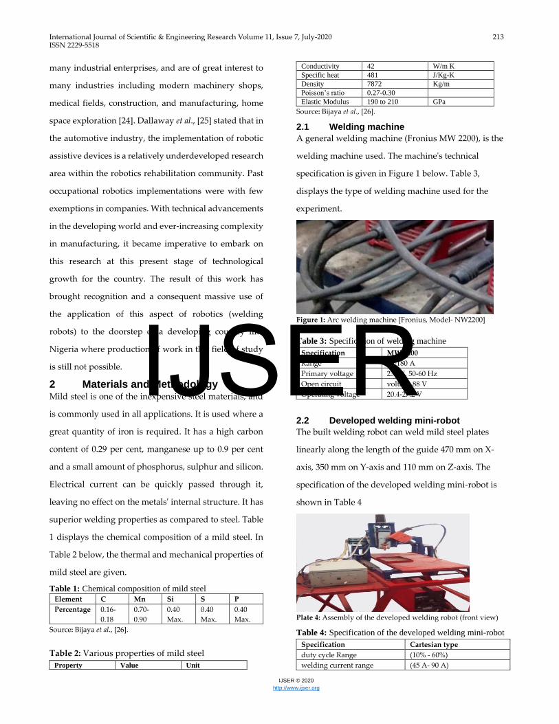
2.1 Welding machine
A general welding machine (Fronius MW 2200), is the
welding machine used. The machine's technical
specification is given in Figure 1 below. Table 3,
displays the type of welding machine used for the
experiment.
Figure 1: Arc welding machine [Fronius, Model- NW2200]
Table 3: Specification of welding machine
Specification MW 2200
Range 10-180 A
Primary voltage 230 V, 50-60 Hz
Open circuit voltage 88 V
Operating voltage 20.4-27.2 V
2.2 Developed welding mini-robot
The built welding robot can weld mild steel plates
linearly along the length of the guide 470 mm on X-
axis, 350 mm on Y-axis and 110 mm on Z-axis. The
specification of the developed welding mini-robot is
shown in Table 4
Plate 4: Assembly of the developed welding robot (front view)
Table 4: Specification of the developed welding mini-robot
Specification Cartesian type
duty cycle Range (10% - 60%)
welding current range (45 A- 90 A)
IJSER
International Journal of Scientific & Engineering Research Volume 11, Issue 7, July-2020 214 ISSN 2229-5518
IJSER © 2020
http://www.ijser.org
welding voltage range (16.25 V – 18.5 V)
electrode size 0.8 mm
2.3 Experimental parameter
In welding process current was varied along with the
thickness of work piece. The current is varied in three
steps as shown in following Table 4.
Table 4: Experimental parameter
2.4 Experimental methodology
60 specimens of the thickness 0.5, 0.6, 0.7, 0.8, 0.9 and 1
mm are considered for performing the experiment.
Before the specimens were welded, the oil in a molten
metal tub was washed off dust to eliminate impurities.
Since welding was performed through a closed butt
joint, the edges of the piece of work are prepared
accordingly. To conduct the welding the work pieces
were held in relative place. Safety precautions and
corrective steps were taken to avoid accidents and to
achieve good weld bead efficiency.
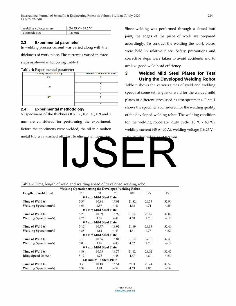
3 Welded Mild Steel Plates for Test
Using the Developed Welding Robot
Table 5 shows the various times of weld and welding
speeds at some set lengths of weld for the welded mild
plates of different sizes used as test specimens. Plate 1
shows the specimens considered for the welding quality
of the developed welding robot. The welding condition
for the welding robot are: duty cycle (10 % - 60 %),
welding current (45 A- 90 A), welding voltage (16.25 V –
18.5 V), electrode size of 0.8 mm.
Table 5: Time, length of weld and welding speed of developed welding robot Welding Operation using the Developed Welding Robot
Length of Weld (mm) 25 50 75 100 125 150
0.5 mm Mild Steel Plate
Time of Weld (s) 5.37 10.94 17.01 21.82 26.53 32.94
Welding Speed (mm/s) 4.66 4.57 4.41 4.58 4.71 4.55
0.6 mm Mild Steel Plate
Time of Weld (s) 5.25 10.89 16.99 21.74 26.45 32.82
Welding Speed (mm/s) 4.76 4.59 4.41 4.60 4.73 4.57
0.7 mm Mild Steel Plate
Time of Weld (s) 5.12 10.77 16.92 21.69 26.33 32.44
Welding Speed (mm/s) 4.88 4.64 4.43 4.61 4.75 4.62
0.8 mm Mild Steel Plate
Time of Weld (s) 5 10.66 16.84 21.64 26.3 32.43
Welding Speed (mm/s) 5.00 4.69 4.45 4.62 4.75 4.63
0.9 mm Mild Steel Plate
Time of Weld (s) 4.88 10.58 16.75 21.42 26.02 32.42
lding Speed (mm/s) 5.12 4.73 4.48 4.67 4.80 4.63
1.0 mm Mild Steel Plate
Time of Weld (s) 4.7 10.13 16.51 21.3 25.74 31.52
Welding Speed (mm/s) 5.32 4.94 4.54 4.69 4.86 4.76
IJSER
International Journal of Scientific & Engineering Research Volume 11, Issue 7, July-2020 215 ISSN 2229-5518
IJSER © 2020
http://www.ijser.org
0.5 mm welded mild steel plate specimen 0.6 mm welded mild steel plate specimen
0.7 mm welded mild steel plate specimen 0.8 mm welded mild steel plate specimen
0.9 mm welded mild steel plate specimen 1.0 mm welded mild steel plate specimen
Plate 1: Welded mild steel plate specimens using the developed welding robot
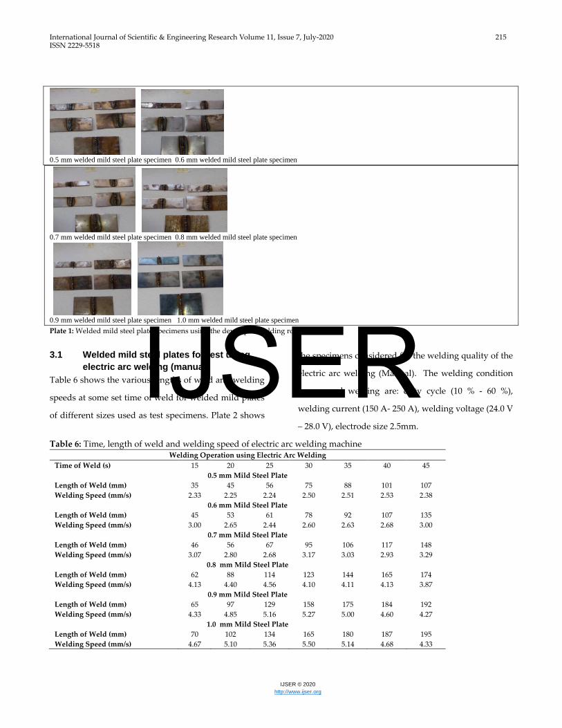
3.1 Welded mild steel plates for test using
electric arc welding (manual)
Table 6 shows the various lengths of weld and welding
speeds at some set time of weld for welded mild plates
of different sizes used as test specimens. Plate 2 shows
the specimens considered for the welding quality of the
electric arc welding (Manual). The welding condition
for manual welding are: duty cycle (10 % - 60 %),
welding current (150 A- 250 A), welding voltage (24.0 V
– 28.0 V), electrode size 2.5mm.
Table 6: Time, length of weld and welding speed of electric arc welding machine Welding Operation using Electric Arc Welding
Time of Weld (s) 15 20 25 30 35 40 45
0.5 mm Mild Steel Plate
Length of Weld (mm) 35 45 56 75 88 101 107
Welding Speed (mm/s) 2.33 2.25 2.24 2.50 2.51 2.53 2.38
0.6 mm Mild Steel Plate
Length of Weld (mm) 45 53 61 78 92 107 135
Welding Speed (mm/s) 3.00 2.65 2.44 2.60 2.63 2.68 3.00
0.7 mm Mild Steel Plate
Length of Weld (mm) 46 56 67 95 106 117 148
Welding Speed (mm/s) 3.07 2.80 2.68 3.17 3.03 2.93 3.29
0.8 mm Mild Steel Plate
Length of Weld (mm) 62 88 114 123 144 165 174
Welding Speed (mm/s) 4.13 4.40 4.56 4.10 4.11 4.13 3.87
0.9 mm Mild Steel Plate
Length of Weld (mm) 65 97 129 158 175 184 192
Welding Speed (mm/s) 4.33 4.85 5.16 5.27 5.00 4.60 4.27
1.0 mm Mild Steel Plate
Length of Weld (mm) 70 102 134 165 180 187 195
Welding Speed (mm/s) 4.67 5.10 5.36 5.50 5.14 4.68 4.33
IJSER
International Journal of Scientific & Engineering Research Volume 11, Issue 7, July-2020 216 ISSN 2229-5518
IJSER © 2020
http://www.ijser.org
0.5 mm welded mild steel plate specimen 0.6 mm welded mild steel plate specimen
0.7 mm welded mild steel plate specimen 0.8 mm welded mild steel plate specimen
0.9 mm welded mild steel plate specimen 1.0 mm welded mild steel plate specimen
Plate 2: Welded mild steel plate specimens using electric arc welding (manual)
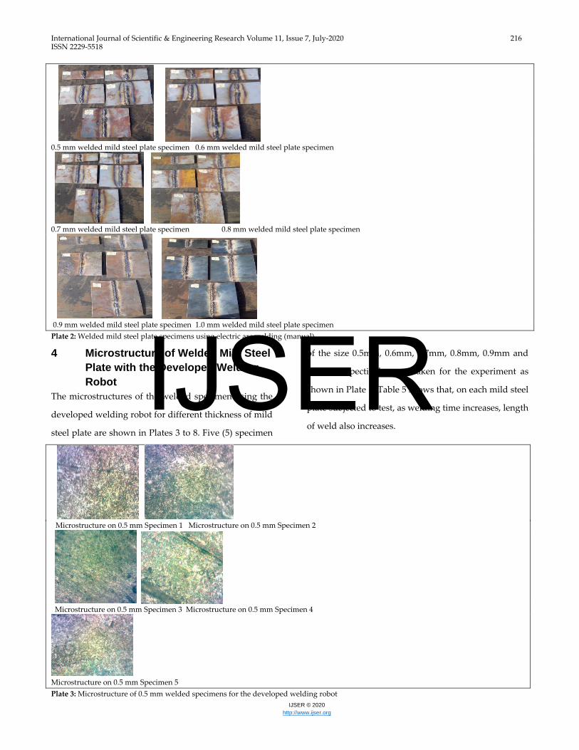
4 Microstructure of Welded Mild Steel
Plate with the Developed Welding
Robot
The microstructures of the welded specimen using the
developed welding robot for different thickness of mild
steel plate are shown in Plates 3 to 8. Five (5) specimen
of the size 0.5mm, 0.6mm, 0.7mm, 0.8mm, 0.9mm and
1.0mm respectively were taken for the experiment as
shown in Plate 1. Table 5 shows that, on each mild steel
plate subjected to test, as welding time increases, length
of weld also increases.
Microstructure on 0.5 mm Specimen 1 Microstructure on 0.5 mm Specimen 2
Microstructure on 0.5 mm Specimen 3 Microstructure on 0.5 mm Specimen 4
Microstructure on 0.5 mm Specimen 5
Plate 3: Microstructure of 0.5 mm welded specimens for the developed welding robot
IJSER
International Journal of Scientific & Engineering Research Volume 11, Issue 7, July-2020 217 ISSN 2229-5518
IJSER © 2020
http://www.ijser.org
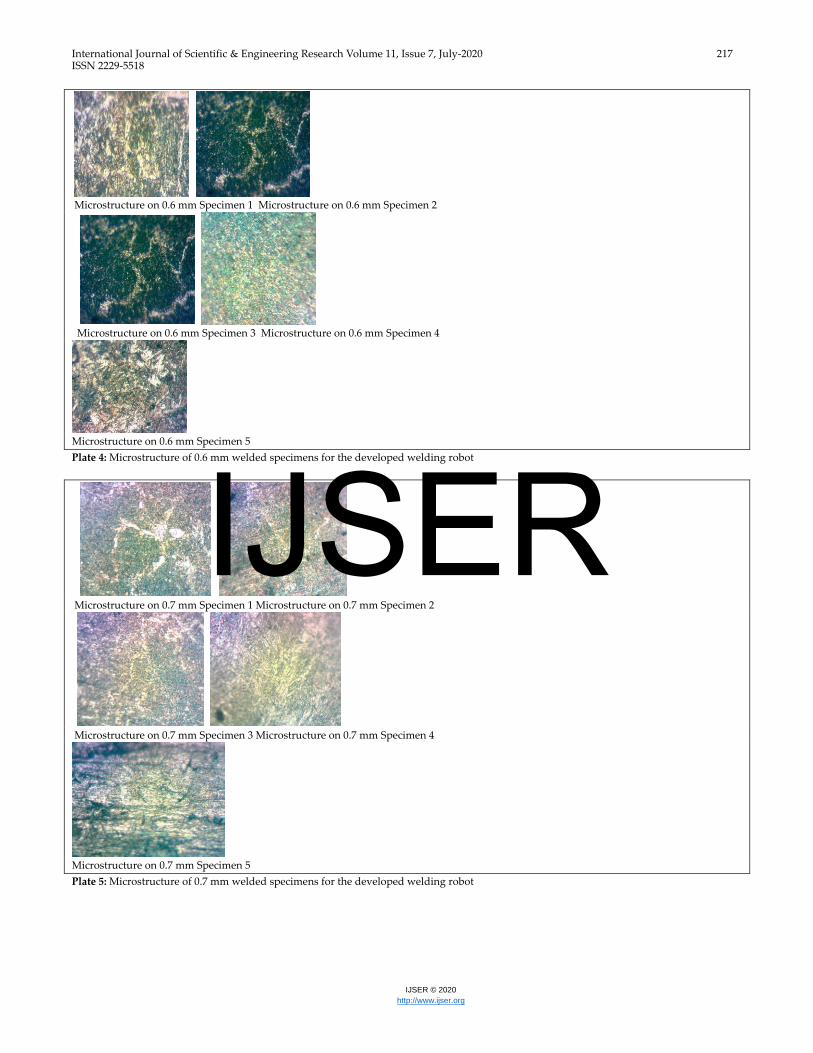
Microstructure on 0.6 mm Specimen 1 Microstructure on 0.6 mm Specimen 2
Microstructure on 0.6 mm Specimen 3 Microstructure on 0.6 mm Specimen 4
Microstructure on 0.6 mm Specimen 5
Plate 4: Microstructure of 0.6 mm welded specimens for the developed welding robot
Microstructure on 0.7 mm Specimen 1 Microstructure on 0.7 mm Specimen 2
Microstructure on 0.7 mm Specimen 3 Microstructure on 0.7 mm Specimen 4
Microstructure on 0.7 mm Specimen 5
Plate 5: Microstructure of 0.7 mm welded specimens for the developed welding robot
IJSER
International Journal of Scientific & Engineering Research Volume 11, Issue 7, July-2020 218 ISSN 2229-5518
IJSER © 2020
http://www.ijser.org
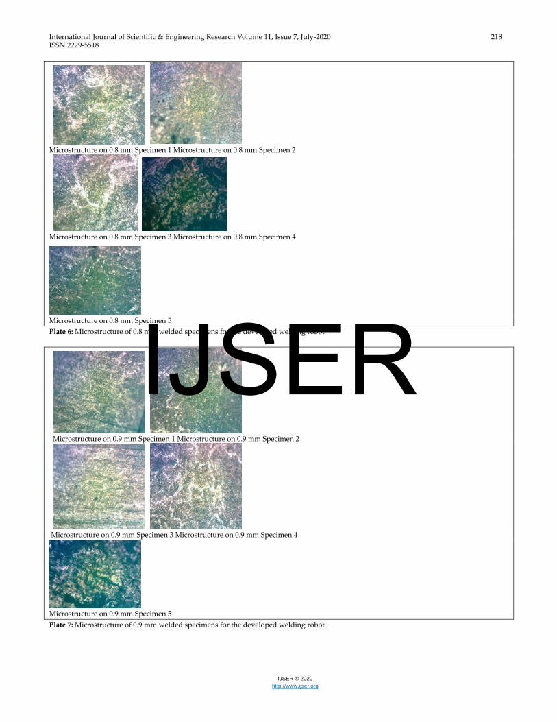
Microstructure on 0.8 mm Specimen 1 Microstructure on 0.8 mm Specimen 2
Microstructure on 0.8 mm Specimen 3 Microstructure on 0.8 mm Specimen 4
Microstructure on 0.8 mm Specimen 5
Plate 6: Microstructure of 0.8 mm welded specimens for the developed welding robot
Microstructure on 0.9 mm Specimen 1 Microstructure on 0.9 mm Specimen 2
Microstructure on 0.9 mm Specimen 3 Microstructure on 0.9 mm Specimen 4
Microstructure on 0.9 mm Specimen 5
Plate 7: Microstructure of 0.9 mm welded specimens for the developed welding robot
IJSER
International Journal of Scientific & Engineering Research Volume 11, Issue 7, July-2020 219 ISSN 2229-5518
IJSER © 2020
http://www.ijser.org
Microstructure on 1.0 mm Specimen 1 Microstructure on 1.0 mm Specimen 2
Microstructure on 1.0 mm Specimen 3 Microstructure on 1.0 mm Specimen 4
Microstructure on 1.0 mm Specimen 5
Plate 8: Microstructure of 1.0 mm welded specimens for the developed welding robot
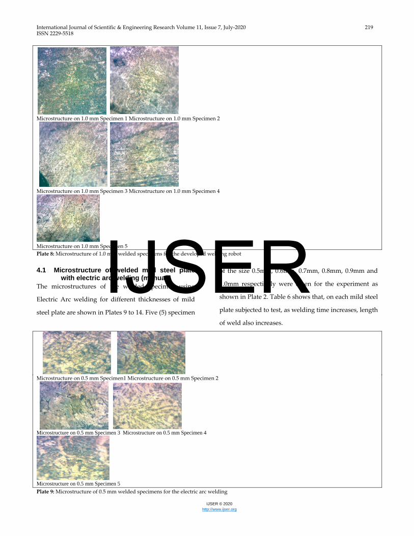
4.1 Microstructure of welded mild steel plate
with electric arc welding (manual)
The microstructures of the welded specimen using
Electric Arc welding for different thicknesses of mild
steel plate are shown in Plates 9 to 14. Five (5) specimen
of the size 0.5mm, 0.6mm, 0.7mm, 0.8mm, 0.9mm and
1.0mm respectively were taken for the experiment as
shown in Plate 2. Table 6 shows that, on each mild steel
plate subjected to test, as welding time increases, length
of weld also increases.
Microstructure on 0.5 mm Specimen1 Microstructure on 0.5 mm Specimen 2
Microstructure on 0.5 mm Specimen 3 Microstructure on 0.5 mm Specimen 4
Microstructure on 0.5 mm Specimen 5
Plate 9: Microstructure of 0.5 mm welded specimens for the electric arc welding
IJSER
International Journal of Scientific & Engineering Research Volume 11, Issue 7, July-2020 220 ISSN 2229-5518
IJSER © 2020
http://www.ijser.org
Microstructure on 0.6 mm Specimen 1 Microstructure on 0.6 mm Specimen 2
Microstructure on 0.6 mm Specimen 3 Microstructure on 0.6 mm Specimen4
Microstructure on 0.6 mm Specimen 5
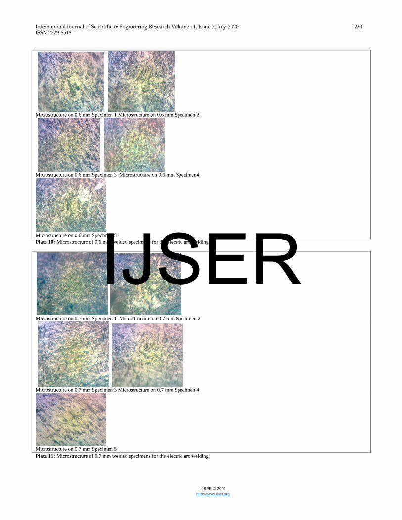
Plate 10: Microstructure of 0.6 mm welded specimens for the electric arc welding
Microstructure on 0.7 mm Specimen 1 Microstructure on 0.7 mm Specimen 2
Microstructure on 0.7 mm Specimen 3 Microstructure on 0.7 mm Specimen 4
Microstructure on 0.7 mm Specimen 5
Plate 11: Microstructure of 0.7 mm welded specimens for the electric arc welding
IJSER
International Journal of Scientific & Engineering Research Volume 11, Issue 7, July-2020 221 ISSN 2229-5518
IJSER © 2020
http://www.ijser.org
Microstructure on 0.8 mm Specimen 1 Microstructure on 0.8 mm Specimen 2
Microstructure on 0.8 mm Specimen 3 Microstructure on 0.8 mm Specimen 4
Microstructure on 0.8 mm Specimen 5
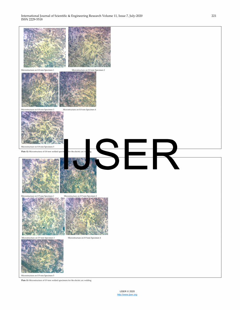
Plate 12: Microstructure of 0.8 mm welded specimens for the electric arc welding
Microstructure on 0.9 mm Specimen 1 Microstructure on 0.9 mm Specimen 2
Microstructure on 0.9 mm Specimen 3 Microstructure on 0.9 mm Specimen 4
Microstructure on 0.9 mm Specimen 5
Plate 13: Microstructure of 0.9 mm welded specimens for the electric arc welding
IJSER
International Journal of Scientific & Engineering Research Volume 11, Issue 7, July-2020 222 ISSN 2229-5518
IJSER © 2020
http://www.ijser.org
Microstructure on 1.0 mm Specimen 1 Microstructure on 1.0 mm Specimen 2
Microstructure on 1.0 mm Specimen 3 Microstructure on 1.0 mm Specimen 4
Microstructure on 1.0 mm Specimen 5
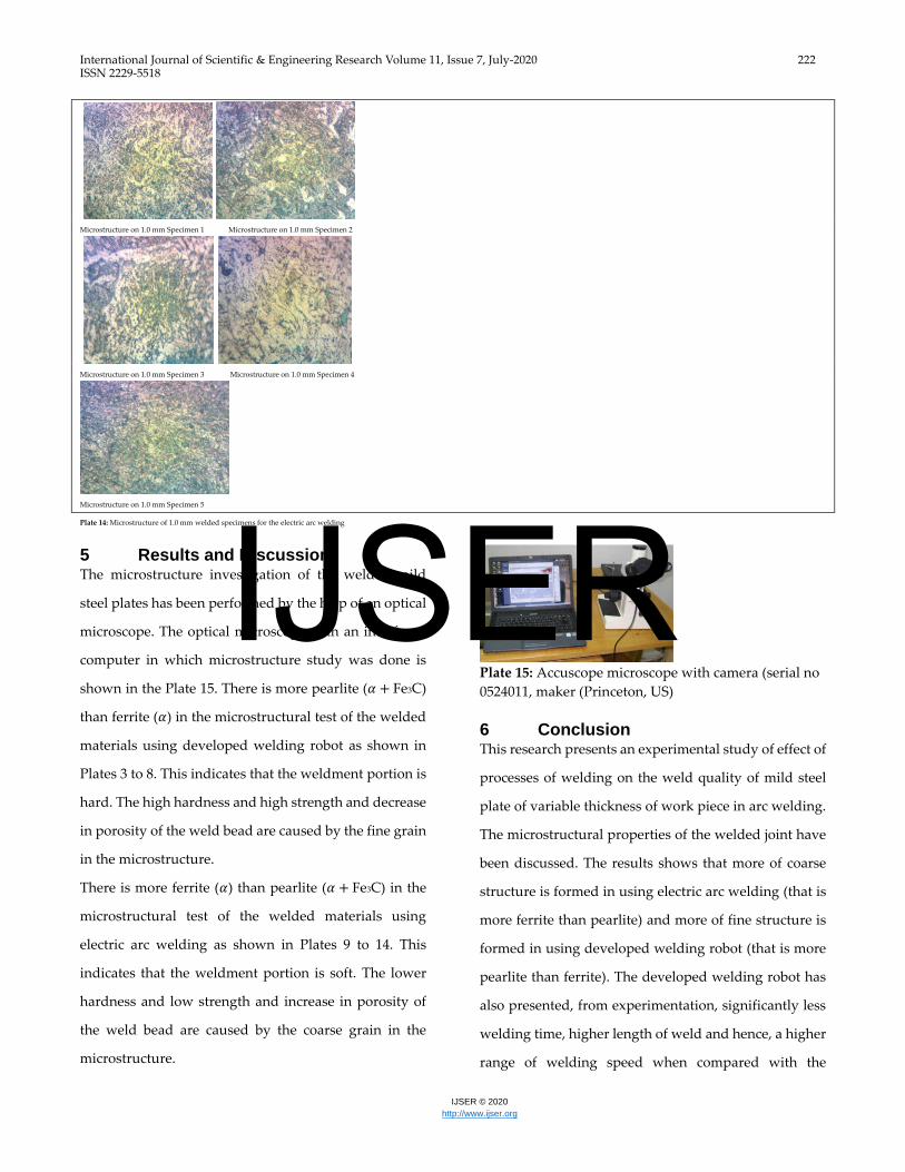
Plate 14: Microstructure of 1.0 mm welded specimens for the electric arc welding
5 Results and Discussion The microstructure investigation of the welded mild
steel plates has been performed by the help of an optical
microscope. The optical microscope with an interfaced
computer in which microstructure study was done is
shown in the Plate 15. There is more pearlite (𝛼 + Fe3C)
than ferrite (𝛼) in the microstructural test of the welded
materials using developed welding robot as shown in
Plates 3 to 8. This indicates that the weldment portion is
hard. The high hardness and high strength and decrease
in porosity of the weld bead are caused by the fine grain
in the microstructure.
There is more ferrite (𝛼) than pearlite (𝛼 + Fe3C) in the
microstructural test of the welded materials using
electric arc welding as shown in Plates 9 to 14. This
indicates that the weldment portion is soft. The lower
hardness and low strength and increase in porosity of
the weld bead are caused by the coarse grain in the
microstructure.
Plate 15: Accuscope microscope with camera (serial no
0524011, maker (Princeton, US)
6 Conclusion This research presents an experimental study of effect of
processes of welding on the weld quality of mild steel
plate of variable thickness of work piece in arc welding.
The microstructural properties of the welded joint have
been discussed. The results shows that more of coarse
structure is formed in using electric arc welding (that is
more ferrite than pearlite) and more of fine structure is
formed in using developed welding robot (that is more
pearlite than ferrite). The developed welding robot has
also presented, from experimentation, significantly less
welding time, higher length of weld and hence, a higher
range of welding speed when compared with the
IJSER
International Journal of Scientific & Engineering Research Volume 11, Issue 7, July-2020 223 ISSN 2229-5518
IJSER © 2020
http://www.ijser.org
conventional electric arc welding technique adopted in
this research work. The developed welding robot is
faster in terms of welding time (4.7-32.94s, as compared
to electric arc welding’s 15-45s); welding speed (starting
from 4.41mm/s , when compared to the electric arc
welding’s starting from 2.24mm/s) over same range of
mild steel plate thicknesses from 0.5-1.0mm and length
of weld. The higher the thickness of the mild steel plate,
the lower the time of weld and the higher the welding
speed. This is true in the use of both the developed
welding robot and electric arc welding machine. The
developed welding robot has worked very well and
presented better quality of weld from the results of
microstructural analyses.
References [1] Bayaraktar, E., Kaplan, D., Devillers, L. and Chevalier,
J. P. (2007). “Grain Growth Mechanism during the
Welding of Inter-stitial Free (IF) Steels,” Journal of
Materials Processing Technology, 189(1-3):114-125.
[2] Karadeniz, E, Ugur, O., and Ceyhan, Y. (2007). The effect
of process parameters on penetration in gas metal arc
welding processes." Materials & design 28(2): 649-656.
[3] Boob, A. N., and Gattani, G. K. (2013). "Study on Effect
of Manual metal arc welding process parameters on
width of heat affected zone (HAZ) for Ms 1005 Steel‖."
International Journal of Modern Engineering Research
(IJMER) 3(3): 1493-1500.
[4] Talabi, S., Owolabi, O. B., Adebisi, J. A. and Yahaya, T.
(2014). "Effect of welding variables on mechanical
properties of low carbon steel welded joint." Advances
in Production Engineering & Management 9(4), 181.
[5] Norman, A. F., Drazhner, V. and Prangnell, P. B. (1999).
"Effect of welding parameters on the solidification
microstructure of autogenous TIG welds in an Al–Cu–
Mg–Mn alloy." Materials Science and Engineering: A
259(1): 53-64.
[6] Haragopal, G., Reddy, P. V. R., Reddy, G. and
Subrahmanyam, J. V. (2011). "Parameter design for MIG
welding of Al-65032 alloy using Taguchi technique."
[7] Sharma, C., Dheerendra, K. D. and Pradeep, K. (2013).
Effect of post weld heat treatments on microstructure
and mechanical properties of friction stir welded joints
of Al–Zn–Mg alloy AA7039." Materials & Design 43:
134-143.
[8] Chandel, R. S., Seow, H. P. and Cheong, F. L. (1997).
"Effect of increasing deposition rate on the bead
geometry of submerged arc welds." Journal of Materials
Processing Technology, 72(1):124-128.
[9] Furuya, H., Aihara, S. and Morita, K. (2007). "A new
proposal of HAZ toughness evaluation Method-Part 1:
Haz toughness of structural steel in multilayer and
single-layer weld joints." Welding Journal-New York-
86(1): 1.
[10] Lakshmanan Vellaichamya, Pradeep Benedict Thomas
Gerarda and Sathiya Paulraj (2018). Mechanical and
Metallurgical Characterization of Laser Welding on P91
Ferritic Steel and Incoloy 800HT Dissimilar Joints,
Materials Research, 21(2): 1-15.
[11] Irfan, S. and Vishal, A. (2014). "An Experimental Study
on the Effect of MIG Welding Parameters on the
Weldability of Galvenize Steel." International Journal on
Emerging Technologies 5(1): 146.
[12] Lienert, T. J., Stellwag Jr, W. L., Grimmett, B. B. and
Warke, R. W. (2003). "Friction stir welding studies on
mild steel." Welding Journal-New York- 82(1): 1-S.
[13] Sato, Y. S., Yamanoi, H., Kokawa, H. and Furuhara, T.
(2007). "Microstructural evolutions of ultrahigh carbon
steel during friction stir welding." Scripta Materialia
57(6): 557-560.
[14] Marashi, P., Majid, P., Sasan, A., Abedi, A.and
Goodarzi, M. (2008). "Microstructure and failure
behavior of dissimilar resistance spot welds between
low carbon galvanized and austenitic stainless steels."
Materials Science and Engineering: A 480(1): 175-180.
[15] Saeid, T., A. Abdollah-Zadeh, H. A. and Ghaini, F. M.
(2008). "Effect of friction stir welding speed on the
microstructure and mechanical properties of a duplex
stainless steel." Materials Science and Engineering: A
496(1): 262-268.
[16] Zakaria, B., Chemseddine, D. and Thierry, B. (2010).
Effect of Welding on Microstructure and Mechanical
Properties of an Industrial Low Carbon Steel, Scientific
Research, 2, 502-506.
[17] Güral, A., Bostan, B. and Özdemir, A. T. (2007). “Heat
Treatment in Two Phase Region and its Effect on
Welding of a Low Carbon Steel,” Materials and Design,
28(3):897-903.
[18] Eroglu and Aksoy, M. (2000). Effect of Initial Grain Size
on Microstructure and Toughness, Materials Science and
Engineering A, 286(2):289-297.
[19] Grong, O. and Akselsen, O. M. (1986). “HAZ Grain
Growth Me-chanism in Welding of Low Carbon
Microalloyed Steels,” Acta Metallurgica, 34(9):1807-1815.
[20] Thaulow, C., Paauw, A. J., Gunleiksrud, A. and Naess,
O. J. (1985). “Heat Affected Zone Toughness of Low
Carbon Micro-alloyed Steel,” Metal Construct, 17(2):94-
99.
[21] Ohaya, K., Kim, J., Yokoyama, K. and Nagumo, M.
(1996). “Mi-crostructures Relevant to Brittle Fracture
Initiation at the Heat-affected Zone of Weldment of
Low Carbon Steel,” Metallurgical and Materials
Transactions A, 27(9):2574-2582.
[22] Olabi, A. G. and Hashmi, M. J. S. (1996). “The
Microstructure and Mechanical Properties of Low
Carbon Steel Welded Components after the Application
of PWHT,” Journal of Material Processing Technology,
56(1-4):88-97.
[23] Anawa, E. M. and Olabi, A. G. (2008). “Using Taguchi
Method to Optimize Welding Pool of Dissimilar Laser-
welded Components,” Optics & Laser Technology, Vol.
40, No. 2, pp. 379-388.
[24] Vinjamuri, R. (2004): Software Porting for Bearcat III
Robot. A M. Sc Dissertation, Department of Mechanical,
IJSER
International Journal of Scientific & Engineering Research Volume 11, Issue 7, July-2020 224 ISSN 2229-5518
IJSER © 2020
http://www.ijser.org
Industrial and Nuclear Engineering, University of
Cincinnati, USA.
[25] Dallaway, J. L., Mahoney, R. M. and Jackson, R. D.
(1994): The Application of Rehabilitation Robotics
within Manufacturing Industry. Proceedings of the
Fourth International Conference on Rehabilitation
Robotics. pp. 145-149.
[26] Bijaya Kumar Khamari, Pradip Kumar Sahu and B B
Biswal (2018). Microstructure Analysis of Arc Welded
Mild Steel Plates, IOP Conf. Ser.: Mater. Sci. Eng. 377: 1-6.
IJSER