Comparative Analysis on Thermal Performance of...
10
AUT Journal of Mechanical Engineering AUT J. Mech. Eng., 1(1) (2017) 39-48 DOI: 10.22060/mej.2017.12314.5310 Comparative Analysis on Thermal Performance of Different Natural-Draft Dry Cooling Towers Under Crosswind Condition M. Goodarzi 1* , P. Mohammadi 2 1 Department of Mechanical Engineering, Bu Ali Sina University, Hamedan, Iran 2 Department of Mechanical Engineering, Takestan Branch of Islamic Azad University, Takestan, Iran ABSTRACT: This article aims to study the thermal performances of four different natural draft cooling towers under crosswind condition. The windbreakers and the oblique exit plane have been simultaneously included in the structure of the new cooling tower. A finite volume method using SIMPLE algorithm was used to simulate the flow field around each cooling tower. The thermal performance of the new geometry has been compared with those of others for the generally investigated wind velocity profile for 10 m/s, and also two uniform wind velocities for 3 and 7 m/s. The cooling capacity of the cooling tower utilizing windbreakers and the oblique exit plane was predicted as 98.3% of the design value in the presence of generally studied wind velocity profile of 10 m/s, while that of the cooling tower utilizing windbreakers was predicted as 93.5%. Of course, the percentage of the thermal improvements of the different restoring strategies are sensitive to the profile of an approaching wind. The uniform wind velocity decreases the thermal efficiency of the cooling tower more than the distributed one, while the restoring strategies using windbreakers provide a higher percentage of thermal improvements in the presence of uniform wind velocity. Review History: Received: 3 January 2017 Revised: 17 April 2017 Accepted: 17 April 2017 Available Online: 23 April 2017 Keywords: Cooling tower Crosswind Windbreaker Oblique exit plane Cooling efficiency 39 1- Introduction The cooling tower is one of the important units in a steam power plant. It rejects a large amount of the heat absorbed from the steam within the condenser to the ambient. Some steam power plants use wet cooling towers when there are enough water resources near the site. They should use dry cooling towers at the regions with rare water resources. A natural draft cooling tower supplies the ambient airflow into the cooling tower across the radiators or fills packing without any mechanical facilities. A large amount of the warmed air inside the cooling tower makes a buoyancy force for lifting the airflow toward the top of the cooling tower. Therefore, a natural draft cooling tower consists of a huge structure to provide the large volume of the warmed air. The finned tube heat exchangers are usually installed at the bottom of the natural draft cooling tower. They are usually subdivided into several radiator sectors and a particular water distributor system feeds the hot water into them. The hot water exchanges heat with airflow crossing the radiators, and slightly decreases the air density entering the cooling tower. Buoyant airflow sucks the outdoor air into the cooling tower across the vertically installed radiators. The technical reports state that the cooling efficiency of the natural draft cooling tower decreases under crosswind condition [1]. Two elements causing this deficiency were qualitatively examined within a wind tunnel, but not quantitatively. Since an experimental small scale of the cooling tower cannot provide the buoyant upward airflow, many researchers decided to study the thermal and hydraulic performances of the natural draft dry cooling tower with a numerical full-scale simulation. Demuren and Rodi [2] simply modeled the cooling tower as a vertical cylinder to study the flow field from the hydrodynamic viewpoint. Bender et al. [3] numerically calculated the intake flow rate in a real geometry of the cooling tower. Bergstrom et al. [4] numerically studied the wind flowing over a cooling tower and reported some features of the wind effects on the flow patterns. Du Preez and Kroger [5] numerically defined the main unfavorable elements decreasing the cooling efficiency. Other researchers such as We et al. [6], Su et al. [7], and Al- Waked and Behnia [8] identically showed that two elements decreased the cooling efficiency of the cooling tower under crosswind condition; accelerated flow near the sideward radiators trailing with separated flow behind the rearward radiators, and deflected plume exiting the tower stack. Under crosswind condition, the airflow accelerates near the sideward radiators and locally decreases the outdoor pressure. The unfavorable pressure gradient near the rear radiator sectors causes the flow to be separated. Hence, there are radiator sectors exposing to low pressure difference. Therefore, the total mass-flow rate of the airflow across the radiator sectors is lessened compared to the normal condition. Consequently, the total heat rejection capacity decreases. Moreover, the deflected plume throttles the air passage through the tower stack. This increases the indoor pressure, and consequently, decreases the total pressure difference between indoor and outdoor. Many researchers have concentrated on the accelerated flow near the sideward radiator sectors and proposed the windbreakers to decelerate the velocity of the airflow at this location. At first, Du Preez and Kroger [9] suggested this idea. Corresponding author, E-mail: [email protected]
Transcript of Comparative Analysis on Thermal Performance of...
AUT Journal of Mechanical Engineering
AUT J. Mech. Eng., 1(1) (2017) 39-48DOI: 10.22060/mej.2017.12314.5310
Comparative Analysis on Thermal Performance of Different Natural-Draft Dry Cooling Towers Under Crosswind Condition
M. Goodarzi1*, P. Mohammadi2
1 Department of Mechanical Engineering, Bu Ali Sina University, Hamedan, Iran2 Department of Mechanical Engineering, Takestan Branch of Islamic Azad University, Takestan, Iran
ABSTRACT: This article aims to study the thermal performances of four different natural draft cooling towers under crosswind condition. The windbreakers and the oblique exit plane have been simultaneously included in the structure of the new cooling tower. A finite volume method using SIMPLE algorithm was used to simulate the flow field around each cooling tower. The thermal performance of the new geometry has been compared with those of others for the generally investigated wind velocity profile for 10 m/s, and also two uniform wind velocities for 3 and 7 m/s. The cooling capacity of the cooling tower utilizing windbreakers and the oblique exit plane was predicted as 98.3% of the design value in the presence of generally studied wind velocity profile of 10 m/s, while that of the cooling tower utilizing windbreakers was predicted as 93.5%. Of course, the percentage of the thermal improvements of the different restoring strategies are sensitive to the profile of an approaching wind. The uniform wind velocity decreases the thermal efficiency of the cooling tower more than the distributed one, while the restoring strategies using windbreakers provide a higher percentage of thermal improvements in the presence of uniform wind velocity.
Review History:
Received: 3 January 2017Revised: 17 April 2017Accepted: 17 April 2017Available Online: 23 April 2017
Keywords:
Cooling towerCrosswindWindbreakerOblique exit planeCooling efficiency
39
1- IntroductionThe cooling tower is one of the important units in a steam power plant. It rejects a large amount of the heat absorbed from the steam within the condenser to the ambient. Some steam power plants use wet cooling towers when there are enough water resources near the site. They should use dry cooling towers at the regions with rare water resources. A natural draft cooling tower supplies the ambient airflow into the cooling tower across the radiators or fills packing without any mechanical facilities. A large amount of the warmed air inside the cooling tower makes a buoyancy force for lifting the airflow toward the top of the cooling tower. Therefore, a natural draft cooling tower consists of a huge structure to provide the large volume of the warmed air.The finned tube heat exchangers are usually installed at the bottom of the natural draft cooling tower. They are usually subdivided into several radiator sectors and a particular water distributor system feeds the hot water into them. The hot water exchanges heat with airflow crossing the radiators, and slightly decreases the air density entering the cooling tower. Buoyant airflow sucks the outdoor air into the cooling tower across the vertically installed radiators.The technical reports state that the cooling efficiency of the natural draft cooling tower decreases under crosswind condition [1]. Two elements causing this deficiency were qualitatively examined within a wind tunnel, but not quantitatively. Since an experimental small scale of the cooling tower cannot provide the buoyant upward airflow, many researchers decided to study the thermal and hydraulic
performances of the natural draft dry cooling tower with a numerical full-scale simulation.Demuren and Rodi [2] simply modeled the cooling tower as a vertical cylinder to study the flow field from the hydrodynamic viewpoint. Bender et al. [3] numerically calculated the intake flow rate in a real geometry of the cooling tower. Bergstrom et al. [4] numerically studied the wind flowing over a cooling tower and reported some features of the wind effects on the flow patterns. Du Preez and Kroger [5] numerically defined the main unfavorable elements decreasing the cooling efficiency. Other researchers such as We et al. [6], Su et al. [7], and Al-Waked and Behnia [8] identically showed that two elements decreased the cooling efficiency of the cooling tower under crosswind condition; accelerated flow near the sideward radiators trailing with separated flow behind the rearward radiators, and deflected plume exiting the tower stack. Under crosswind condition, the airflow accelerates near the sideward radiators and locally decreases the outdoor pressure. The unfavorable pressure gradient near the rear radiator sectors causes the flow to be separated. Hence, there are radiator sectors exposing to low pressure difference. Therefore, the total mass-flow rate of the airflow across the radiator sectors is lessened compared to the normal condition. Consequently, the total heat rejection capacity decreases. Moreover, the deflected plume throttles the air passage through the tower stack. This increases the indoor pressure, and consequently, decreases the total pressure difference between indoor and outdoor. Many researchers have concentrated on the accelerated flow near the sideward radiator sectors and proposed the windbreakers to decelerate the velocity of the airflow at this location. At first, Du Preez and Kroger [9] suggested this idea.
Corresponding author, E-mail: [email protected]
M. Goodarzi and P. Mohammadi, AUT J. Mech. Eng., 1(1) (2017) 39-48, DOI: 10.22060/mej.2017.12314.5310
40
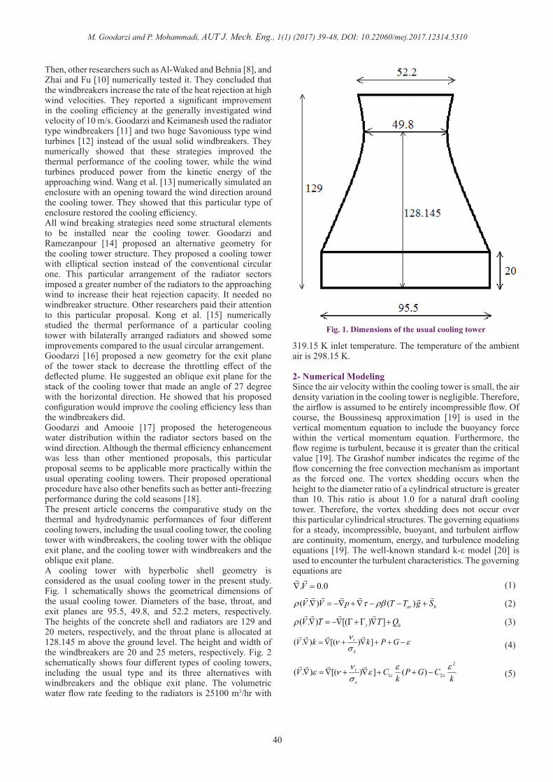
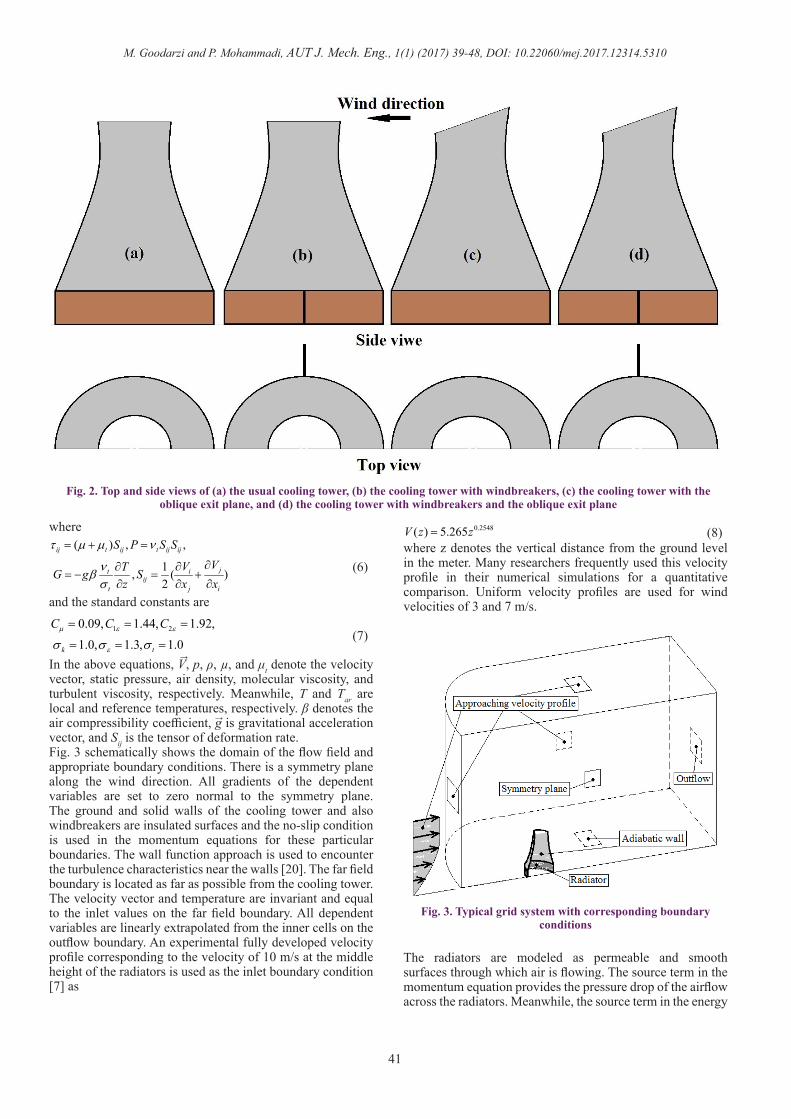
Then, other researchers such as Al-Waked and Behnia [8], and Zhai and Fu [10] numerically tested it. They concluded that the windbreakers increase the rate of the heat rejection at high wind velocities. They reported a significant improvement in the cooling efficiency at the generally investigated wind velocity of 10 m/s. Goodarzi and Keimanesh used the radiator type windbreakers [11] and two huge Savoniouss type wind turbines [12] instead of the usual solid windbreakers. They numerically showed that these strategies improved the thermal performance of the cooling tower, while the wind turbines produced power from the kinetic energy of the approaching wind. Wang et al. [13] numerically simulated an enclosure with an opening toward the wind direction around the cooling tower. They showed that this particular type of enclosure restored the cooling efficiency.All wind breaking strategies need some structural elements to be installed near the cooling tower. Goodarzi and Ramezanpour [14] proposed an alternative geometry for the cooling tower structure. They proposed a cooling tower with elliptical section instead of the conventional circular one. This particular arrangement of the radiator sectors imposed a greater number of the radiators to the approaching wind to increase their heat rejection capacity. It needed no windbreaker structure. Other researchers paid their attention to this particular proposal. Kong et al. [15] numerically studied the thermal performance of a particular cooling tower with bilaterally arranged radiators and showed some improvements compared to the usual circular arrangement. Goodarzi [16] proposed a new geometry for the exit plane of the tower stack to decrease the throttling effect of the deflected plume. He suggested an oblique exit plane for the stack of the cooling tower that made an angle of 27 degree with the horizontal direction. He showed that his proposed configuration would improve the cooling efficiency less than the windbreakers did.Goodarzi and Amooie [17] proposed the heterogeneous water distribution within the radiator sectors based on the wind direction. Although the thermal efficiency enhancement was less than other mentioned proposals, this particular proposal seems to be applicable more practically within the usual operating cooling towers. Their proposed operational procedure have also other benefits such as better anti-freezing performance during the cold seasons [18]. The present article concerns the comparative study on the thermal and hydrodynamic performances of four different cooling towers, including the usual cooling tower, the cooling tower with windbreakers, the cooling tower with the oblique exit plane, and the cooling tower with windbreakers and the oblique exit plane.A cooling tower with hyperbolic shell geometry is considered as the usual cooling tower in the present study. Fig. 1 schematically shows the geometrical dimensions of the usual cooling tower. Diameters of the base, throat, and exit planes are 95.5, 49.8, and 52.2 meters, respectively. The heights of the concrete shell and radiators are 129 and 20 meters, respectively, and the throat plane is allocated at 128.145 m above the ground level. The height and width of the windbreakers are 20 and 25 meters, respectively. Fig. 2 schematically shows four different types of cooling towers, including the usual type and its three alternatives with windbreakers and the oblique exit plane. The volumetric water flow rate feeding to the radiators is 25100 m3/hr with
319.15 K inlet temperature. The temperature of the ambient air is 298.15 K.
2- Numerical ModelingSince the air velocity within the cooling tower is small, the air density variation in the cooling tower is negligible. Therefore, the airflow is assumed to be entirely incompressible flow. Of course, the Boussinesq approximation [19] is used in the vertical momentum equation to include the buoyancy force within the vertical momentum equation. Furthermore, the flow regime is turbulent, because it is greater than the critical value [19]. The Grashof number indicates the regime of the flow concerning the free convection mechanism as important as the forced one. The vortex shedding occurs when the height to the diameter ratio of a cylindrical structure is greater than 10. This ratio is about 1.0 for a natural draft cooling tower. Therefore, the vortex shedding does not occur over this particular cylindrical structures. The governing equations for a steady, incompressible, buoyant, and turbulent airflow are continuity, momentum, energy, and turbulence modeling equations [19]. The well-known standard k-ε model [20] is used to encounter the turbulent characteristics. The governing equations are
. 0.0V∇ =
(1)
( . ) ( )ar hV V p T T g Sρ τ ρβ∇ = −∇ +∇ − − +
(2)
( . ) [( ) ]t hV T T Qρ ∇ = −∇ Γ +Γ ∇ +
(3)
( . ) [( ) ]t
k
V k k P Gνν εσ
∇ = ∇ + ∇ + + −
(4)
2
1 2( . ) [( ) ] ( )tV C P G Ck kε ε
ε
ν ε εε ν εσ
∇ = ∇ + ∇ + + −
(5)
Fig. 1. Dimensions of the usual cooling tower
M. Goodarzi and P. Mohammadi, AUT J. Mech. Eng., 1(1) (2017) 39-48, DOI: 10.22060/mej.2017.12314.5310
41
where( ) , ,
1, ( )2
ij t ij t ij ij
jt iij
t j i
S P S SVVTG g S
z x x
τ µ µ ν
νβσ
= + =
∂∂∂= − = +
∂ ∂ ∂(6)
and the standard constants are
1 20.09, 1.44, 1.92,1.0, 1.3, 1.0k t
C C Cµ ε ε
εσ σ σ
= = =
= = =(7)
In the above equations, V, p, ρ, µ, and μt denote the velocity vector, static pressure, air density, molecular viscosity, and turbulent viscosity, respectively. Meanwhile, T and Tar are local and reference temperatures, respectively. β denotes the air compressibility coefficient, g is gravitational acceleration vector, and Sij is the tensor of deformation rate.Fig. 3 schematically shows the domain of the flow field and appropriate boundary conditions. There is a symmetry plane along the wind direction. All gradients of the dependent variables are set to zero normal to the symmetry plane. The ground and solid walls of the cooling tower and also windbreakers are insulated surfaces and the no-slip condition is used in the momentum equations for these particular boundaries. The wall function approach is used to encounter the turbulence characteristics near the walls [20]. The far field boundary is located as far as possible from the cooling tower. The velocity vector and temperature are invariant and equal to the inlet values on the far field boundary. All dependent variables are linearly extrapolated from the inner cells on the outflow boundary. An experimental fully developed velocity profile corresponding to the velocity of 10 m/s at the middle height of the radiators is used as the inlet boundary condition [7] as
0.2548( ) 5.265V z z= (8)where z denotes the vertical distance from the ground level in the meter. Many researchers frequently used this velocity profile in their numerical simulations for a quantitative comparison. Uniform velocity profiles are used for wind velocities of 3 and 7 m/s.
The radiators are modeled as permeable and smooth surfaces through which air is flowing. The source term in the momentum equation provides the pressure drop of the airflow across the radiators. Meanwhile, the source term in the energy
Fig. 2. Top and side views of (a) the usual cooling tower, (b) the cooling tower with windbreakers, (c) the cooling tower with the oblique exit plane, and (d) the cooling tower with windbreakers and the oblique exit plane
→
→
Fig. 3. Typical grid system with corresponding boundary conditions
M. Goodarzi and P. Mohammadi, AUT J. Mech. Eng., 1(1) (2017) 39-48, DOI: 10.22060/mej.2017.12314.5310
42
equation provides the rate of the heat transfer to the airflow across the radiators. Technical information of the Forgo heat exchangers [21] correlates the pressure drop of the airflow across the radiators in term of the local normal component of the air velocity. The usual equation to compute the pressure drop of the airflow across the radiators is
212 v np k Vρ∆ = (9)
where the pressure drop coefficient is computed from the following experimental correlation [22]
0.2413.03 0.436v nk V −= + (10)There is an experimental correlation to compute the convective heat transfer coefficient [22] as
0.5152035.2 nh V= (11)Radiator temperature is set to the average of the inlet and outlet water temperatures as follows
2wi wo
rT TT +
= (12)
It should be iteratively computed during the numerical procedure. When a numerical iteration takes place, the rate of the heat transfer from the radiators is computed as
( )r r rQ A h T T= − (13)
where Ar is the surface of the heat transfer, i.e. surface of a particular radiator sector. Then, the outlet water temperature (Two) is computed from the energy balance over the particular radiator sector
( )r w w wi woQ m C T T= −
(14)
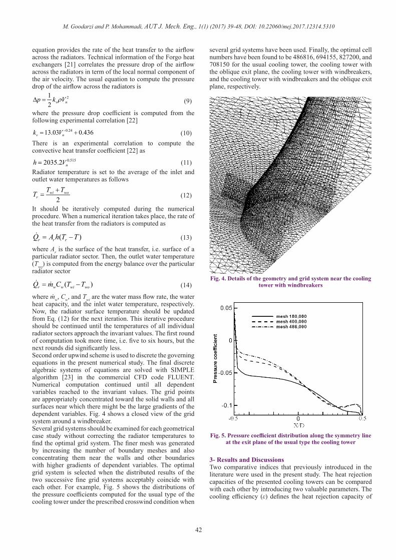
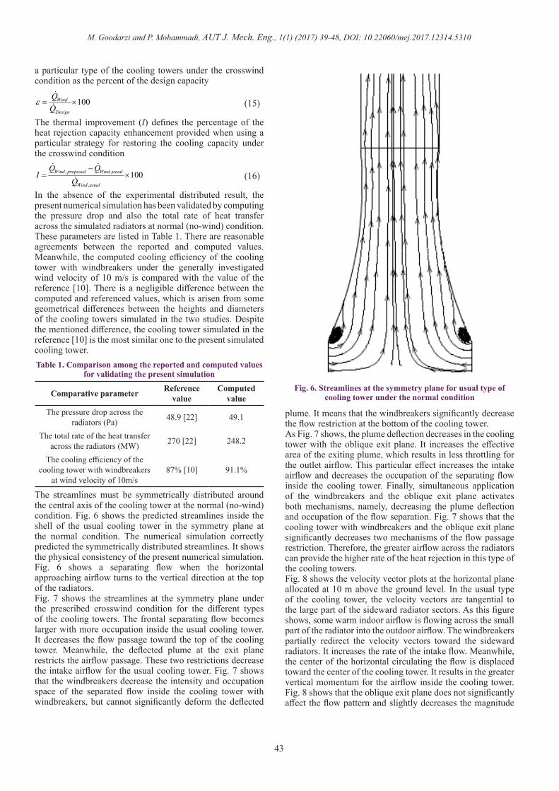
where mw, Cw, and Twi are the water mass flow rate, the water heat capacity, and the inlet water temperature, respectively. Now, the radiator surface temperature should be updated from Eq. (12) for the next iteration. This iterative procedure should be continued until the temperatures of all individual radiator sectors approach the invariant values. The first round of computation took more time, i.e. five to six hours, but the next rounds did significantly less.Second order upwind scheme is used to discrete the governing equations in the present numerical study. The final discrete algebraic systems of equations are solved with SIMPLE algorithm [23] in the commercial CFD code FLUENT. Numerical computation continued until all dependent variables reached to the invariant values. The grid points are appropriately concentrated toward the solid walls and all surfaces near which there might be the large gradients of the dependent variables. Fig. 4 shows a closed view of the grid system around a windbreaker. Several grid systems should be examined for each geometrical case study without correcting the radiator temperatures to find the optimal grid system. The finer mesh was generated by increasing the number of boundary meshes and also concentrating them near the walls and other boundaries with higher gradients of dependent variables. The optimal grid system is selected when the distributed results of the two successive fine grid systems acceptably coincide with each other. For example, Fig. 5 shows the distributions of the pressure coefficients computed for the usual type of the cooling tower under the prescribed crosswind condition when
several grid systems have been used. Finally, the optimal cell numbers have been found to be 486816, 694155, 827200, and 708150 for the usual cooling tower, the cooling tower with the oblique exit plane, the cooling tower with windbreakers, and the cooling tower with windbreakers and the oblique exit plane, respectively.
3- Results and Discussions Two comparative indices that previously introduced in the literature were used in the present study. The heat rejection capacities of the presented cooling towers can be compared with each other by introducing two valuable parameters. The cooling efficiency (ε) defines the heat rejection capacity of
.
Fig. 4. Details of the geometry and grid system near the cooling tower with windbreakers
Fig. 5. Pressure coefficient distribution along the symmetry line at the exit plane of the usual type the cooling tower
M. Goodarzi and P. Mohammadi, AUT J. Mech. Eng., 1(1) (2017) 39-48, DOI: 10.22060/mej.2017.12314.5310
43
a particular type of the cooling towers under the crosswind condition as the percent of the design capacity
100Wind
Design
ε = ×
(15)
The thermal improvement (I) defines the percentage of the heat rejection capacity enhancement provided when using a particular strategy for restoring the cooling capacity under the crosswind condition
, ,
,
100Wind proposed Wind usual
Wind usual
Q QI
Q−
= ×
(16)
In the absence of the experimental distributed result, the present numerical simulation has been validated by computing the pressure drop and also the total rate of heat transfer across the simulated radiators at normal (no-wind) condition. These parameters are listed in Table 1. There are reasonable agreements between the reported and computed values. Meanwhile, the computed cooling efficiency of the cooling tower with windbreakers under the generally investigated wind velocity of 10 m/s is compared with the value of the reference [10]. There is a negligible difference between the computed and referenced values, which is arisen from some geometrical differences between the heights and diameters of the cooling towers simulated in the two studies. Despite the mentioned difference, the cooling tower simulated in the reference [10] is the most similar one to the present simulated cooling tower.
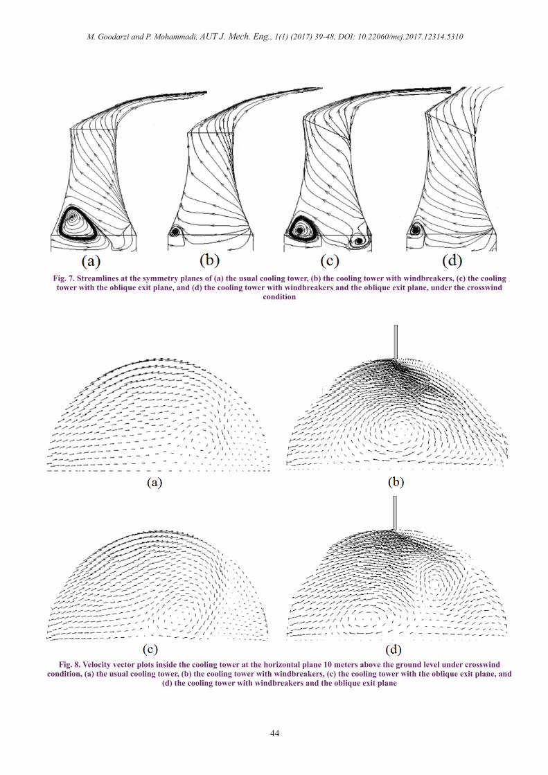
The streamlines must be symmetrically distributed around the central axis of the cooling tower at the normal (no-wind) condition. Fig. 6 shows the predicted streamlines inside the shell of the usual cooling tower in the symmetry plane at the normal condition. The numerical simulation correctly predicted the symmetrically distributed streamlines. It shows the physical consistency of the present numerical simulation. Fig. 6 shows a separating flow when the horizontal approaching airflow turns to the vertical direction at the top of the radiators.Fig. 7 shows the streamlines at the symmetry plane under the prescribed crosswind condition for the different types of the cooling towers. The frontal separating flow becomes larger with more occupation inside the usual cooling tower. It decreases the flow passage toward the top of the cooling tower. Meanwhile, the deflected plume at the exit plane restricts the airflow passage. These two restrictions decrease the intake airflow for the usual cooling tower. Fig. 7 shows that the windbreakers decrease the intensity and occupation space of the separated flow inside the cooling tower with windbreakers, but cannot significantly deform the deflected
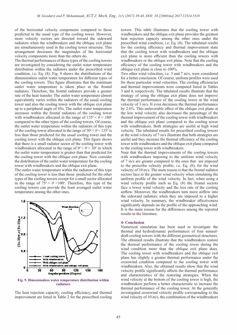
plume. It means that the windbreakers significantly decrease the flow restriction at the bottom of the cooling tower.As Fig. 7 shows, the plume deflection decreases in the cooling tower with the oblique exit plane. It increases the effective area of the exiting plume, which results in less throttling for the outlet airflow. This particular effect increases the intake airflow and decreases the occupation of the separating flow inside the cooling tower. Finally, simultaneous application of the windbreakers and the oblique exit plane activates both mechanisms, namely, decreasing the plume deflection and occupation of the flow separation. Fig. 7 shows that the cooling tower with windbreakers and the oblique exit plane significantly decreases two mechanisms of the flow passage restriction. Therefore, the greater airflow across the radiators can provide the higher rate of the heat rejection in this type of the cooling towers.Fig. 8 shows the velocity vector plots at the horizontal plane allocated at 10 m above the ground level. In the usual type of the cooling tower, the velocity vectors are tangential to the large part of the sideward radiator sectors. As this figure shows, some warm indoor airflow is flowing across the small part of the radiator into the outdoor airflow. The windbreakers partially redirect the velocity vectors toward the sideward radiators. It increases the rate of the intake flow. Meanwhile, the center of the horizontal circulating the flow is displaced toward the center of the cooling tower. It results in the greater vertical momentum for the airflow inside the cooling tower. Fig. 8 shows that the oblique exit plane does not significantly affect the flow pattern and slightly decreases the magnitude
Comparative parameter Reference value
Computed value
The pressure drop across the radiators (Pa) 48.9 [22] 49.1
The total rate of the heat transfer across the radiators (MW) 270 [22] 248.2
The cooling efficiency of the cooling tower with windbreakers
at wind velocity of 10m/s87% [10] 91.1%
Table 1. Comparison among the reported and computed values for validating the present simulation
Fig. 6. Streamlines at the symmetry plane for usual type of cooling tower under the normal condition
M. Goodarzi and P. Mohammadi, AUT J. Mech. Eng., 1(1) (2017) 39-48, DOI: 10.22060/mej.2017.12314.5310
44
Fig. 7. Streamlines at the symmetry planes of (a) the usual cooling tower, (b) the cooling tower with windbreakers, (c) the cooling tower with the oblique exit plane, and (d) the cooling tower with windbreakers and the oblique exit plane, under the crosswind
condition
Fig. 8. Velocity vector plots inside the cooling tower at the horizontal plane 10 meters above the ground level under crosswind condition, (a) the usual cooling tower, (b) the cooling tower with windbreakers, (c) the cooling tower with the oblique exit plane, and
(d) the cooling tower with windbreakers and the oblique exit plane
M. Goodarzi and P. Mohammadi, AUT J. Mech. Eng., 1(1) (2017) 39-48, DOI: 10.22060/mej.2017.12314.5310
45
of the horizontal velocity components compared to those predicted in the usual type of the cooling tower. However, more velocity vectors are directed toward the sideward radiators when the windbreakers and the oblique exit plane are simultaneously used in the cooling tower structure. This arrangement decreases the magnitudes of the horizontal velocity components more than the others do.The thermal performances of these types of the cooling towers are investigated by considering the outlet water temperature distribution within the radiators under the prescribed wind condition, i.e. Eq. (8). Fig. 9 shows the distributions of the dimensionless outlet water temperature for different types of the cooling towers. This figure illustrates that the minimum outlet water temperature is taken place at the frontal radiators. Therefore, the frontal radiators provide a greater rate of the heat transfer. The outlet water temperature almost equivalently varies within the radiators of the usual cooling tower and also the cooling tower with the oblique exit plane up to a peripheral angle of 45o. The outlet water temperature increases within the frontal radiators of the cooling tower with windbreakers allocated in the range of 135o < θ < 180o
compared to the other types of the cooling towers. Of course, the outlet water temperature within the radiators of this type of the cooling tower allocated in the range of 30o < θ < 135o is less than those predicted for the usual cooling tower and the cooling tower with the oblique exit plane. This figure shows that there is a small radiator sector of the cooling tower with windbreakers allocated in the range of 0o < θ < 30o in which the outlet water temperature is greater than that predicted for the cooling tower with the oblique exit plane. Now consider the distribution of the outlet water temperature for the cooling tower with windbreakers and the oblique exit plane. The outlet water temperature within the radiators of this type of the cooling tower is less than those predicted for the other types of the cooling towers except for a small sector allocated in the range of 75o < θ <100o. Therefore, this type of the cooling towers can provide the least averaged outlet water temperature among the other ones.
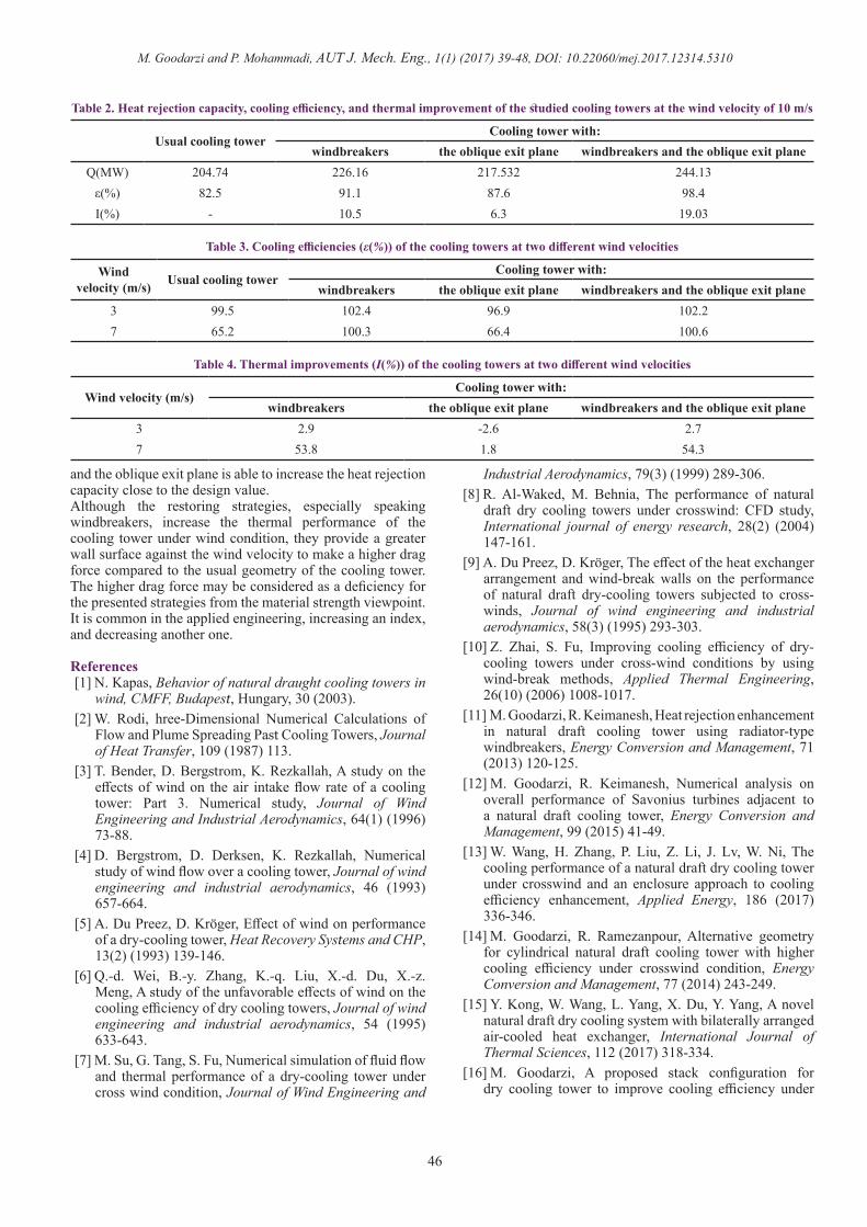
The heat rejection capacity, cooling efficiency, and thermal improvement are listed in Table 2 for the prescribed cooling
towers. This table illustrates that the cooling tower with windbreakers and the oblique exit plane provides the greatest heat rejection capacity among the other ones under the prescribed wind condition, i.e. Eq. (8). The tabulated results for the cooling efficiency and thermal improvement state that the cooling tower with windbreakers and the oblique exit plane is more efficient than the cooling towers with windbreakers or the oblique exit plane. Note that the cooling efficiency of the cooling tower with windbreakers and the oblique exit plane is close to 100%.Two other wind velocities, i.e. 3 and 7 m/s, were considered for a better conclusion. Of course, uniform profiles were used for these particular wind velocities. The cooling efficiencies and thermal improvements were computed listed in Tables 3 and 4, respectively. The tabulated results illustrate that the strategy of using the oblique exit plane does not improve the thermal performance of the cooling tower at the wind velocity of 3 m/s. It even decreases the thermal performance by 2.6%. This unfavorable effect of the oblique exit plane at the low wind velocity also decreases the percentage of the thermal improvement of the cooling tower with windbreakers and the oblique exit plane compared to the cooling tower with windbreakers. Both strategies are useful at high wind velocity. The tabulated results for prescribed cooling towers at the wind velocity of 7 m/s illustrate that both strategies are useful and they increase the thermal efficiency of the cooling tower with windbreakers and the oblique exit plane compared to the cooling tower with windbreakers.Note that the thermal improvements of the cooling towers with windbreakers imposing to the uniform wind velocity of 7 m/s are greater compared to the ones that are imposed to the prescribe velocity profile, i.e. Eq. (8), for the wind velocity of 10 m/s. The main reason is that the frontal radiator sectors face to the greater wind velocity when simulating the uniform profile of the wind velocity. In fact, when using a wind velocity profile such as Eq. (8) the frontal sectors face a lower wind velocity and the less rate of the cooling airflow. Moreover, the windbreakers turn more airflow into the sideward radiators when they are imposed to a higher wind velocity. In summary, the windbreaker effectiveness significantly depends on the profile of the approaching wind. It is the main reason for the differences among the reported results in the literature.
4- ConclusionNumerical simulation has been used to investigate the thermal and hydrodynamic performances of four natural-draft cooling towers with the different geometrical structures. The obtained results illustrate that the windbreakers restore the thermal performance of the cooling tower during the wind condition more than the oblique exit plane does. The cooling tower with windbreakers and the oblique exit plane has slightly a greater thermal performance under the crosswind condition compared to the cooling tower with windbreakers. Also, the obtained results show that the wind velocity profile significantly affects the thermal performance and characteristics of the restoring strategies. When the wind velocity at the bottom of the cooling tower is high, the windbreakers perform a better characteristic to increase the thermal performance of the cooling tower. At the generally investigated crosswind velocity profile corresponding to the wind velocity of 10 m/s, the combination of the windbreakers
Fig. 9. Dimensionless water temperature distribution within radiators
M. Goodarzi and P. Mohammadi, AUT J. Mech. Eng., 1(1) (2017) 39-48, DOI: 10.22060/mej.2017.12314.5310
46
and the oblique exit plane is able to increase the heat rejection capacity close to the design value.Although the restoring strategies, especially speaking windbreakers, increase the thermal performance of the cooling tower under wind condition, they provide a greater wall surface against the wind velocity to make a higher drag force compared to the usual geometry of the cooling tower. The higher drag force may be considered as a deficiency for the presented strategies from the material strength viewpoint. It is common in the applied engineering, increasing an index, and decreasing another one.
References[1] N. Kapas, Behavior of natural draught cooling towers in
wind, CMFF, Budapest, Hungary, 30 (2003).[2] W. Rodi, hree-Dimensional Numerical Calculations of
Flow and Plume Spreading Past Cooling Towers, Journal of Heat Transfer, 109 (1987) 113.
[3] T. Bender, D. Bergstrom, K. Rezkallah, A study on the effects of wind on the air intake flow rate of a cooling tower: Part 3. Numerical study, Journal of Wind Engineering and Industrial Aerodynamics, 64(1) (1996) 73-88.
[4] D. Bergstrom, D. Derksen, K. Rezkallah, Numerical study of wind flow over a cooling tower, Journal of wind engineering and industrial aerodynamics, 46 (1993) 657-664.
[5] A. Du Preez, D. Kröger, Effect of wind on performance of a dry-cooling tower, Heat Recovery Systems and CHP, 13(2) (1993) 139-146.
[6] Q.-d. Wei, B.-y. Zhang, K.-q. Liu, X.-d. Du, X.-z. Meng, A study of the unfavorable effects of wind on the cooling efficiency of dry cooling towers, Journal of wind engineering and industrial aerodynamics, 54 (1995) 633-643.
[7] M. Su, G. Tang, S. Fu, Numerical simulation of fluid flow and thermal performance of a dry-cooling tower under cross wind condition, Journal of Wind Engineering and
Industrial Aerodynamics, 79(3) (1999) 289-306.[8] R. Al‐Waked, M. Behnia, The performance of natural
draft dry cooling towers under crosswind: CFD study, International journal of energy research, 28(2) (2004) 147-161.
[9] A. Du Preez, D. Kröger, The effect of the heat exchanger arrangement and wind-break walls on the performance of natural draft dry-cooling towers subjected to cross-winds, Journal of wind engineering and industrial aerodynamics, 58(3) (1995) 293-303.
[10] Z. Zhai, S. Fu, Improving cooling efficiency of dry-cooling towers under cross-wind conditions by using wind-break methods, Applied Thermal Engineering, 26(10) (2006) 1008-1017.
[11] M. Goodarzi, R. Keimanesh, Heat rejection enhancement in natural draft cooling tower using radiator-type windbreakers, Energy Conversion and Management, 71 (2013) 120-125.
[12] M. Goodarzi, R. Keimanesh, Numerical analysis on overall performance of Savonius turbines adjacent to a natural draft cooling tower, Energy Conversion and Management, 99 (2015) 41-49.
[13] W. Wang, H. Zhang, P. Liu, Z. Li, J. Lv, W. Ni, The cooling performance of a natural draft dry cooling tower under crosswind and an enclosure approach to cooling efficiency enhancement, Applied Energy, 186 (2017) 336-346.
[14] M. Goodarzi, R. Ramezanpour, Alternative geometry for cylindrical natural draft cooling tower with higher cooling efficiency under crosswind condition, Energy Conversion and Management, 77 (2014) 243-249.
[15] Y. Kong, W. Wang, L. Yang, X. Du, Y. Yang, A novel natural draft dry cooling system with bilaterally arranged air-cooled heat exchanger, International Journal of Thermal Sciences, 112 (2017) 318-334.
[16] M. Goodarzi, A proposed stack configuration for dry cooling tower to improve cooling efficiency under
Usual cooling towerCooling tower with:
windbreakers the oblique exit plane windbreakers and the oblique exit planeQ(MW) 204.74 226.16 217.532 244.13
ε(%) 82.5 91.1 87.6 98.4I(%) - 10.5 6.3 19.03
Table 2. Heat rejection capacity, cooling efficiency, and thermal improvement of the studied cooling towers at the wind velocity of 10 m/s
Wind velocity (m/s) Usual cooling tower
Cooling tower with:windbreakers the oblique exit plane windbreakers and the oblique exit plane
3 99.5 102.4 96.9 102.27 65.2 100.3 66.4 100.6
Table 3. Cooling efficiencies (ε(%)) of the cooling towers at two different wind velocities
Wind velocity (m/s)Cooling tower with:
windbreakers the oblique exit plane windbreakers and the oblique exit plane3 2.9 -2.6 2.77 53.8 1.8 54.3
Table 4. Thermal improvements (I(%)) of the cooling towers at two different wind velocities
M. Goodarzi and P. Mohammadi, AUT J. Mech. Eng., 1(1) (2017) 39-48, DOI: 10.22060/mej.2017.12314.5310
47
crosswind, Journal of Wind Engineering and Industrial Aerodynamics, 98(12) (2010) 858-863.
[17] M. Goodarzi, H. Amooie, Heat transfer enhancement in a natural draft dry cooling tower under crosswind operation with heterogeneous water distribution, Atw. Internationale Zeitschrift fuer Kernenergie, 61(4) (2016) 252-259.
[18] W. Wang, L. Yang, X. Du, Y. Yang, Anti-freezing water flow rates of various sectors for natural draft dry cooling system under wind conditions, International Journal of Heat and Mass Transfer, 102 (2016) 186-200.
[19] B. Gebhart, Y. Jaluria, R.L. Mahajan, B. Sammakia,
Buoyancy-induced flows and transport, (1988).[20] B.E. Launder, D.B. Spalding, The numerical
computation of turbulent flows, Computer methods in applied mechanics and engineering, 3(2) (1974) 269-289.
[21] EGI, The Heller System, EGI, 1984.[22] EGI, Thermo Technical and Aerodynamic Design/
Calculation/ Characteristics of the Dry Cooling Plant System Heater, Budapest Institute of Engineering, 1985.
[23] S. Patankar, Numerical heat transfer and fluid flow, CRC press, 1980.
Please cite this article using:
M. Goodarzi and P. Mohammadi, “Comparative Analysis on Thermal Performance of Different Natural-Draft Dry
Cooling Towers Under Crosswind Condition”, AUT J. Mech. Eng., 1(1) (2017) 39-48.
DOI: 10.22060/mej.2017.12314.5310