Comparative Analysis of Impurity Transport in the ...
10
Plasma and Fusion Research: Regular Articles Volume 14, 3403057 (2019) Comparative Analysis of Impurity Transport in the Peripheral Plasma in the Large Helical Device for Carbon and Tungsten Divertor Configurations with EMC3-EIRENE ∗) Mamoru SHOJI 1) and Gakushi KAWAMURA 1,2) 1) National Institute for Fusion Science, National Institutes of Natural Sciences, Toki 509-5292, Japan 2) Department of Fusion Science, Graduate University for Advanced Studies (SOKENDAI), Toki 509-5292, Japan (Received 27 December 2018 / Accepted 17 February 2019) Impurity transport in the peripheral plasma in the Large Helical Device for carbon and tungsten divertor configurations is analyzed using a three-dimensional edge plasma simulation code (EMC3-EIRENE). Long pulse plasma discharges in LHD have often been interrupted by the emission of iron dust from the surface of the vacuum vessel. The iron ions in the peripheral plasma originating from the iron dust can enhance the sputtering of impurities on the divertor plates. The influence on the peripheral plasma by the sputtered impurities is investigated in the iron dust emission case for both the carbon and the tungsten divertor configurations. The simulation reveals that the dependence of the radiation power by the sputtered impurities on the plasma density and the iron emission rate is quite different between the two divertor configurations. It is found that, for the tungsten divertor, a high plasma density operation is advantageous for controlling the radiation power and the impurity ion content. In the high plasma density operation, the radiation power by tungsten ions is suppressed to less than that by carbon ions for the carbon divertor even in the case of high iron dust emission rates due to the reduced sputtering rate by lowered divertor electron temperatures. c 2019 The Japan Society of Plasma Science and Nuclear Fusion Research Keywords: impurity transport, tungsten, carbon, divertor, EMC3-EIRENE, LHD DOI: 10.1585/pfr.14.3403057 1. Introduction Recent long pulse discharges in the Large Helical De- vice (LHD) have often been interrupted by a carbon dust emission from the divertor region caused by the exfoli- ation of carbon dominant mixed-material deposition lay- ers [1,2]. The conventional carbon divertor plates will be replaced to tungsten plates in near future for suppressing the deposition layers. It is expected that the newly installed tungsten divertor plates will contribute to the extension of the duration time of the long pulse discharges as a result of the low sputtering rate of tungsten. However, the sput- tered tungsten can interrupt the plasma discharges by the higher cooling rate due to highly charged tungsten ions in the plasma. For adopting the tungsten divertor, there is a concern about the sustainment of long pulse discharges. That is, electric arcing on the surface of the vacuum vessel has been frequently observed during the plasma discharges with abrupt increase in the iron ion intensity in the plasma, where large amounts of iron dust were released by the elec- tric arcing [3]. The dust enters the peripheral plasma, and iron ions are produced because iron is the main component of the vacuum vessel (SUS316L). The iron ions can trigger author’s e-mail: [email protected] ∗) This article is based on the presentation at the 27th International Toki Conference (ITC27) & the 13th Asia Pacific Plasma Theory Conference (APPTC2018). the physical sputtering of tungsten on the divertor plates by acceleration of the iron ions by the sheath potential formed in front of the divertor plates. In order to understand the characteristics of the tung- sten divertor compared to that of the conventional carbon divertor, a fully three-dimensional edge plasma simulation code (EMC3-EIRENE) is applied [4, 5]. The influence on the peripheral plasma by the sputtered impurities (car- bon and tungsten) is surveyed in various plasma densities, plasma heating powers, and iron emission rates for both the divertor configurations. The simulations contribute to not only finding the optimized experimental condition for suppressing the influence of the sputtered impurities, but also to understanding the characteristics of both the carbon and the tungsten divertor configurations in more detail. 2. Setup of Impurity Transport Simu- lation in the Peripheral Plasma The EMC3-EIRENE calculates a steady-state solution of the three-dimensional profile of peripheral plasma pa- rameters including the effect of the impurity ion transport. The simulation is performed in a three-dimensional grid model as shown in Fig. 1. This model includes an ergodic layer around the Last Closed Flux Surface (LCFS), diver- tor legs, divertor components, and the vacuum vessel for c 2019 The Japan Society of Plasma Science and Nuclear Fusion Research 3403057-1
Transcript of Comparative Analysis of Impurity Transport in the ...

Plasma and Fusion Research: Regular Articles Volume 14, 3403057 (2019)
Comparative Analysis of Impurity Transport in the PeripheralPlasma in the Large Helical Device for Carbon and Tungsten
Divertor Configurations with EMC3-EIRENE∗)
Mamoru SHOJI1) and Gakushi KAWAMURA1,2)
1)National Institute for Fusion Science, National Institutes of Natural Sciences, Toki 509-5292, Japan2)Department of Fusion Science, Graduate University for Advanced Studies (SOKENDAI), Toki 509-5292, Japan
(Received 27 December 2018 / Accepted 17 February 2019)
Impurity transport in the peripheral plasma in the Large Helical Device for carbon and tungsten divertorconfigurations is analyzed using a three-dimensional edge plasma simulation code (EMC3-EIRENE). Long pulseplasma discharges in LHD have often been interrupted by the emission of iron dust from the surface of thevacuum vessel. The iron ions in the peripheral plasma originating from the iron dust can enhance the sputtering ofimpurities on the divertor plates. The influence on the peripheral plasma by the sputtered impurities is investigatedin the iron dust emission case for both the carbon and the tungsten divertor configurations. The simulation revealsthat the dependence of the radiation power by the sputtered impurities on the plasma density and the iron emissionrate is quite different between the two divertor configurations. It is found that, for the tungsten divertor, a highplasma density operation is advantageous for controlling the radiation power and the impurity ion content. Inthe high plasma density operation, the radiation power by tungsten ions is suppressed to less than that by carbonions for the carbon divertor even in the case of high iron dust emission rates due to the reduced sputtering rate bylowered divertor electron temperatures.
c© 2019 The Japan Society of Plasma Science and Nuclear Fusion Research
Keywords: impurity transport, tungsten, carbon, divertor, EMC3-EIRENE, LHD
DOI: 10.1585/pfr.14.3403057
1. IntroductionRecent long pulse discharges in the Large Helical De-
vice (LHD) have often been interrupted by a carbon dustemission from the divertor region caused by the exfoli-ation of carbon dominant mixed-material deposition lay-ers [1, 2]. The conventional carbon divertor plates will bereplaced to tungsten plates in near future for suppressingthe deposition layers. It is expected that the newly installedtungsten divertor plates will contribute to the extension ofthe duration time of the long pulse discharges as a resultof the low sputtering rate of tungsten. However, the sput-tered tungsten can interrupt the plasma discharges by thehigher cooling rate due to highly charged tungsten ions inthe plasma. For adopting the tungsten divertor, there isa concern about the sustainment of long pulse discharges.That is, electric arcing on the surface of the vacuum vesselhas been frequently observed during the plasma dischargeswith abrupt increase in the iron ion intensity in the plasma,where large amounts of iron dust were released by the elec-tric arcing [3]. The dust enters the peripheral plasma, andiron ions are produced because iron is the main componentof the vacuum vessel (SUS316L). The iron ions can trigger
author’s e-mail: [email protected]∗) This article is based on the presentation at the 27th International TokiConference (ITC27) & the 13th Asia Pacific Plasma Theory Conference(APPTC2018).
the physical sputtering of tungsten on the divertor plates byacceleration of the iron ions by the sheath potential formedin front of the divertor plates.
In order to understand the characteristics of the tung-sten divertor compared to that of the conventional carbondivertor, a fully three-dimensional edge plasma simulationcode (EMC3-EIRENE) is applied [4, 5]. The influenceon the peripheral plasma by the sputtered impurities (car-bon and tungsten) is surveyed in various plasma densities,plasma heating powers, and iron emission rates for boththe divertor configurations. The simulations contribute tonot only finding the optimized experimental condition forsuppressing the influence of the sputtered impurities, butalso to understanding the characteristics of both the carbonand the tungsten divertor configurations in more detail.
2. Setup of Impurity Transport Simu-lation in the Peripheral PlasmaThe EMC3-EIRENE calculates a steady-state solution
of the three-dimensional profile of peripheral plasma pa-rameters including the effect of the impurity ion transport.The simulation is performed in a three-dimensional gridmodel as shown in Fig. 1. This model includes an ergodiclayer around the Last Closed Flux Surface (LCFS), diver-tor legs, divertor components, and the vacuum vessel for
c© 2019 The Japan Society of PlasmaScience and Nuclear Fusion Research
3403057-1

Plasma and Fusion Research: Regular Articles Volume 14, 3403057 (2019)
Fig. 1 A perspective view of a three-dimensional grid modelused in the EMC3-EIRENE for a typical magnetic con-figuration (Rax = 3.60 m) in the case of the iron dust emis-sion. The poloidal cross-section of the grid cells for theLHD peripheral plasma at the toroidal angle where theiron source exists (φ = 10.625◦) is described as a groupof small fine black cells.
one-half of the helical coil pitch angle (0◦ ≤ φ ≤ 18◦ intoroidal direction φ), in which the radial position of themagnetic axis Rax is set to be 3.60 m (one of the mosttypical magnetic configurations in LHD). At both toroidaledges of the model, a periodical boundary condition isadopted. The material on the surface of the vacuum ves-sel is regarded as iron. All the divertor components consistof tungsten/carbon for tungsten/carbon divertor configura-tions, respectively.
The impurity ion density profile in the peripheralplasma is obtained by solving the particle and the mo-mentum balance equations of the impurity ions alongmagnetic field lines under the assumption that the im-purity ion temperature is equal to the plasma ion tem-perature. The radiation power by the impurities andthe ionization/recombination coefficients are derived fromthe database on the Atomic Data and Analysis Structure(ADAS) [6]. The position of the iron source locates ona surface on a helical coil can in the inboard side of thetorus. This position corresponds to the location where elec-tric arcing was actually initiated at the termination of along pulse discharge [3]. A number of test particles rep-resenting iron atoms (two million at the maximum) with akinetic energy corresponding to the boiling temperature ofiron (0.26 eV) are launched from this position to deuteriumplasmas.
The perpendicular particle and thermal diffusion co-efficients (D⊥ and χ⊥) are assumed to be 0.5 m2/s and1.5 m2/s, respectively. The profile of the plasma param-eters and the impurities is obtained as a converged solu-tion. It is found that the EMC3-EIRENE cannot provide
the converged solution when the averaged divertor electrontemperature is less than several eV. Three input parame-ters must be defined for carrying out the simulation. Thefirst and second ones are the plasma heating power PLCFS
and the plasma density nLCFSe at the core-SOL boundary
(defined just inside the LCFS). The third parameter is theemission rate of the iron atoms IFe0 released from the po-sition of the iron source. The bulk neutral particles (deu-terium atoms and molecules) are recycled in the grid model(no bulk particle sink exists). The impurity ions arrivingat the core-SOL boundary are reflected to the peripheralplasma while maintaining the charge states of the ions. Theimpurity atoms/ions reaching to the divertor componentsor the vacuum vessel are treated along the following pro-cedures.
The original EMC3-EIRENE does not include phys-ical sputtering (chemical and self-sputtering have alreadybeen implemented in the code). Thus, a variable chemi-cal sputtering rate has been newly introduced as a pseudo-sputtering rate which includes both the chemical and thephysical sputtering rates [7,8]. The value of this sputteringrate is changed during the iterative calculation processesfor obtaining the converged solution. The sputtering rateis varied with the averaged electron and ion temperaturein front of the divertor plates taking account of the chargestate of the incident impurity ions [9]. An energy of 10 eVis adopted as the kinetic energy of the sputtered tungstenatoms from the tungsten divertor plates by both the physi-cal (Fe→W) and the self-sputtering (W→W) [10]. An en-ergy of 0.05 eV is set for the kinetic energy of the sput-tered carbon atoms from the carbon divertor plates, whichequals the energy of the typical divertor plate temperaturein plasma discharges. The kinetic energy of the carbonatoms sputtered by the self-sputtering process (C→C) is setto be 20 eV [7]. The reflection of the incident iron atomsand the tungsten/carbon atoms are not included. The in-fluence of this assumption on the simulation results is es-timated to be less than a few percent at most because ofthe much lower reflection coefficients than the sputteringyields of the impurities.
3. Impurity Transport Analysis3.1 Simulation results for the carbon diver-
torFigure 2 shows the poloidal cross-section of the cal-
culated profile of the carbon and iron ion densities, the ra-diation power by total carbon ions (including carbon ionswith all charge states), and the electron temperature in theperipheral plasma for the carbon divertor. The emissionrate of the iron atoms IFe0 is set to be 6.24 × 10¹⁹ atoms/s.The plasma heating power and the density at the core-SOLboundary are set to be 12 MW and 1 × 10¹⁹ m−3 (a lowplasma density condition), respectively. This figure showsthat while the singly charged carbon ions (C1+) is localizedin both the divertor legs and the outer edge of the ergodic
3403057-2
Plasma and Fusion Research: Regular Articles Volume 14, 3403057 (2019)
Fig. 2 The poloidal cross-section of the profile of the singly charged carbon ions (a), highly charged carbon ions (b), the total carbon iondensity (c), the total iron ion density (d), the radiation power by the carbon ions (e), and the electron temperature in the peripheralplasma (f) for the carbon divertor configuration in a low plasma density condition (PLCFS = 12 MW, nLCFS
e = 1 × 10¹⁹ m−3, and IFe0
= 6.24 × 10¹⁹ atoms/s).
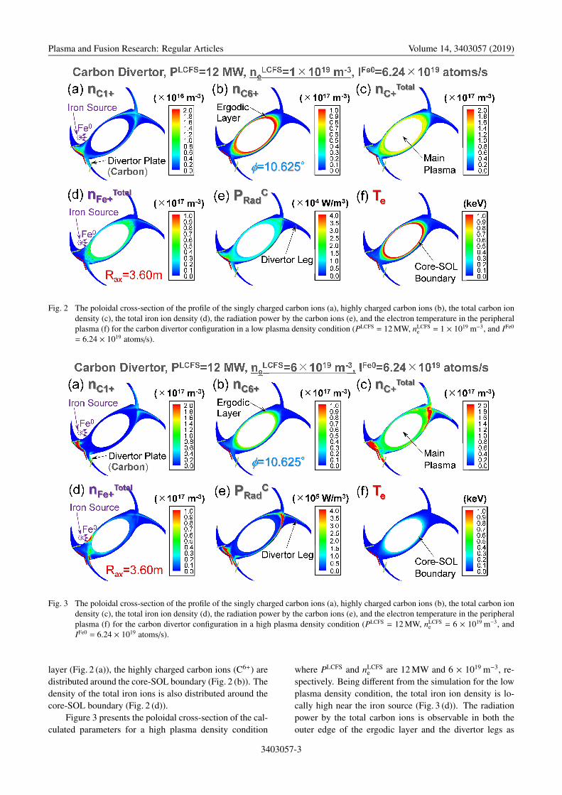
Fig. 3 The poloidal cross-section of the profile of the singly charged carbon ions (a), highly charged carbon ions (b), the total carbon iondensity (c), the total iron ion density (d), the radiation power by the carbon ions (e), and the electron temperature in the peripheralplasma (f) for the carbon divertor configuration in a high plasma density condition (PLCFS = 12 MW, nLCFS
e = 6 × 10¹⁹ m−3, andIFe0 = 6.24 × 10¹⁹ atoms/s).
layer (Fig. 2 (a)), the highly charged carbon ions (C6+) aredistributed around the core-SOL boundary (Fig. 2 (b)). Thedensity of the total iron ions is also distributed around thecore-SOL boundary (Fig. 2 (d)).
Figure 3 presents the poloidal cross-section of the cal-culated parameters for a high plasma density condition
where PLCFS and nLCFSe are 12 MW and 6 × 10¹⁹ m−3, re-
spectively. Being different from the simulation for the lowplasma density condition, the total iron ion density is lo-cally high near the iron source (Fig. 3 (d)). The radiationpower by the total carbon ions is observable in both theouter edge of the ergodic layer and the divertor legs as
3403057-3
Plasma and Fusion Research: Regular Articles Volume 14, 3403057 (2019)
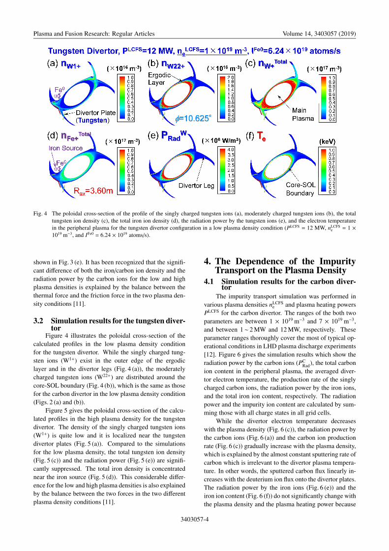
Fig. 4 The poloidal cross-section of the profile of the singly charged tungsten ions (a), moderately charged tungsten ions (b), the totaltungsten ion density (c), the total iron ion density (d), the radiation power by the tungsten ions (e), and the electron temperaturein the peripheral plasma for the tungsten divertor configuration in a low plasma density condition (PLCFS = 12 MW, nLCFS
e = 1 ×10¹⁹ m−3, and IFe0 = 6.24 × 10¹⁹ atoms/s).
shown in Fig. 3 (e). It has been recognized that the signifi-cant difference of both the iron/carbon ion density and theradiation power by the carbon ions for the low and highplasma densities is explained by the balance between thethermal force and the friction force in the two plasma den-sity conditions [11].
3.2 Simulation results for the tungsten diver-tor
Figure 4 illustrates the poloidal cross-section of thecalculated profiles in the low plasma density conditionfor the tungsten divertor. While the singly charged tung-sten ions (W1+) exist in the outer edge of the ergodiclayer and in the divertor legs (Fig. 4 (a)), the moderatelycharged tungsten ions (W22+) are distributed around thecore-SOL boundary (Fig. 4 (b)), which is the same as thosefor the carbon divertor in the low plasma density condition(Figs. 2 (a) and (b)).
Figure 5 gives the poloidal cross-section of the calcu-lated profiles in the high plasma density for the tungstendivertor. The density of the singly charged tungsten ions(W1+) is quite low and it is localized near the tungstendivertor plates (Fig. 5 (a)). Compared to the simulationsfor the low plasma density, the total tungsten ion density(Fig. 5 (c)) and the radiation power (Fig. 5 (e)) are signifi-cantly suppressed. The total iron density is concentratednear the iron source (Fig. 5 (d)). This considerable differ-ence for the low and high plasma densities is also explainedby the balance between the two forces in the two differentplasma density conditions [11].
4. The Dependence of the ImpurityTransport on the Plasma Density
4.1 Simulation results for the carbon diver-tor
The impurity transport simulation was performed invarious plasma densities nLCFS
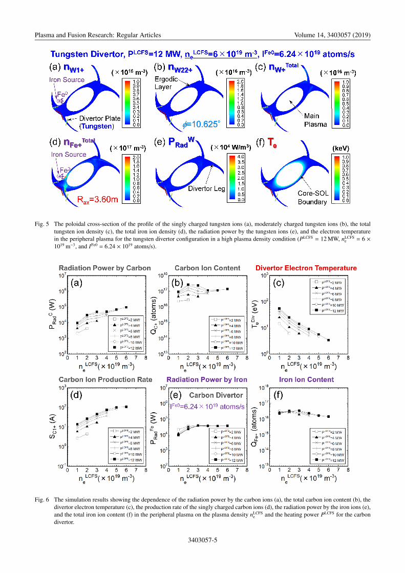
e and plasma heating powersPLCFS for the carbon divertor. The ranges of the both twoparameters are between 1 × 10¹⁹ m−3 and 7 × 10¹⁹ m−3,and between 1∼ 2 MW and 12 MW, respectively. Theseparameter ranges thoroughly cover the most of typical op-erational conditions in LHD plasma discharge experiments[12]. Figure 6 gives the simulation results which show theradiation power by the carbon ions (PC
Rad), the total carbonion content in the peripheral plasma, the averaged diver-tor electron temperature, the production rate of the singlycharged carbon ions, the radiation power by the iron ions,and the total iron ion content, respectively. The radiationpower and the impurity ion content are calculated by sum-ming those with all charge states in all grid cells.
While the divertor electron temperature decreaseswith the plasma density (Fig. 6 (c)), the radiation power bythe carbon ions (Fig. 6 (a)) and the carbon ion productionrate (Fig. 6 (c)) gradually increase with the plasma density,which is explained by the almost constant sputtering rate ofcarbon which is irrelevant to the divertor plasma tempera-ture. In other words, the sputtered carbon flux linearly in-creases with the deuterium ion flux onto the divertor plates.The radiation power by the iron ions (Fig. 6 (e)) and theiron ion content (Fig. 6 (f)) do not significantly change withthe plasma density and the plasma heating power because
3403057-4
Plasma and Fusion Research: Regular Articles Volume 14, 3403057 (2019)
Fig. 5 The poloidal cross-section of the profile of the singly charged tungsten ions (a), moderately charged tungsten ions (b), the totaltungsten ion density (c), the total iron ion density (d), the radiation power by the tungsten ions (e), and the electron temperaturein the peripheral plasma for the tungsten divertor configuration in a high plasma density condition (PLCFS = 12 MW, nLCFS
e = 6 ×10¹⁹ m−3, and IFe0 = 6.24 × 10¹⁹ atoms/s).
Fig. 6 The simulation results showing the dependence of the radiation power by the carbon ions (a), the total carbon ion content (b), thedivertor electron temperature (c), the production rate of the singly charged carbon ions (d), the radiation power by the iron ions (e),and the total iron ion content (f) in the peripheral plasma on the plasma density nLCFS
e and the heating power PLCFS for the carbondivertor.
3403057-5
Plasma and Fusion Research: Regular Articles Volume 14, 3403057 (2019)
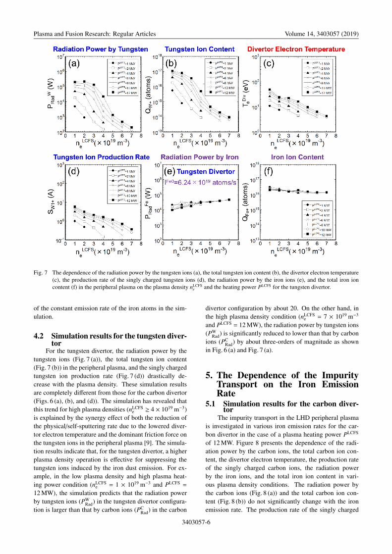
Fig. 7 The dependence of the radiation power by the tungsten ions (a), the total tungsten ion content (b), the divertor electron temperature(c), the production rate of the singly charged tungsten ions (d), the radiation power by the iron ions (e), and the total iron ioncontent (f) in the peripheral plasma on the plasma density nLCFS
e and the heating power PLCFS for the tungsten divertor.
of the constant emission rate of the iron atoms in the sim-ulation.
4.2 Simulation results for the tungsten diver-tor
For the tungsten divertor, the radiation power by thetungsten ions (Fig. 7 (a)), the total tungsten ion content(Fig. 7 (b)) in the peripheral plasma, and the singly chargedtungsten ion production rate (Fig. 7 (d)) drastically de-crease with the plasma density. These simulation resultsare completely different from those for the carbon divertor(Figs. 6 (a), (b), and (d)). The simulation has revealed thatthis trend for high plasma densities (nLCFS
e ≥ 4 × 10¹⁹ m−3)is explained by the synergy effect of both the reduction ofthe physical/self-sputtering rate due to the lowered diver-tor electron temperature and the dominant friction force onthe tungsten ions in the peripheral plasma [9]. The simula-tion results indicate that, for the tungsten divertor, a higherplasma density operation is effective for suppressing thetungsten ions induced by the iron dust emission. For ex-ample, in the low plasma density and high plasma heat-ing power condition (nLCFS
e = 1 × 10¹⁹ m−3 and PLCFS =
12 MW), the simulation predicts that the radiation powerby tungsten ions (PW
Rad) in the tungsten divertor configura-tion is larger than that by carbon ions (PC
Rad) in the carbon
divertor configuration by about 20. On the other hand, inthe high plasma density condition (nLCFS
e = 7 × 10¹⁹ m−3
and PLCFS = 12 MW), the radiation power by tungsten ions(PW
Rad) is significantly reduced to lower than that by carbonions (PC
Rad) by about three-orders of magnitude as shownin Fig. 6 (a) and Fig. 7 (a).
5. The Dependence of the ImpurityTransport on the Iron EmissionRate
5.1 Simulation results for the carbon diver-tor
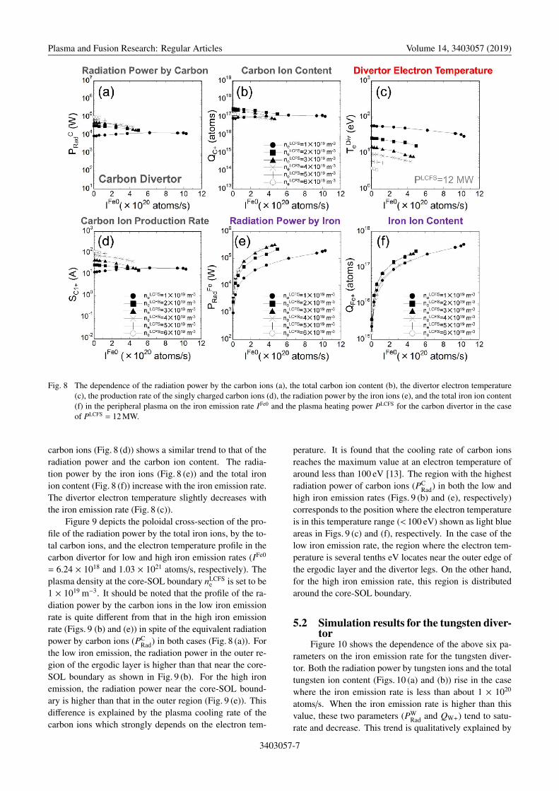
The impurity transport in the LHD peripheral plasmais investigated in various iron emission rates for the car-bon divertor in the case of a plasma heating power PLCFS
of 12 MW. Figure 8 presents the dependence of the radi-ation power by the carbon ions, the total carbon ion con-tent, the divertor electron temperature, the production rateof the singly charged carbon ions, the radiation powerby the iron ions, and the total iron ion content in vari-ous plasma density conditions. The radiation power bythe carbon ions (Fig. 8 (a)) and the total carbon ion con-tent (Fig. 8 (b)) do not significantly change with the ironemission rate. The production rate of the singly charged
3403057-6
Plasma and Fusion Research: Regular Articles Volume 14, 3403057 (2019)
Fig. 8 The dependence of the radiation power by the carbon ions (a), the total carbon ion content (b), the divertor electron temperature(c), the production rate of the singly charged carbon ions (d), the radiation power by the iron ions (e), and the total iron ion content(f) in the peripheral plasma on the iron emission rate IFe0 and the plasma heating power PLCFS for the carbon divertor in the caseof PLCFS = 12 MW.
carbon ions (Fig. 8 (d)) shows a similar trend to that of theradiation power and the carbon ion content. The radia-tion power by the iron ions (Fig. 8 (e)) and the total ironion content (Fig. 8 (f)) increase with the iron emission rate.The divertor electron temperature slightly decreases withthe iron emission rate (Fig. 8 (c)).
Figure 9 depicts the poloidal cross-section of the pro-file of the radiation power by the total iron ions, by the to-tal carbon ions, and the electron temperature profile in thecarbon divertor for low and high iron emission rates (IFe0
= 6.24 × 10¹⁸ and 1.03 × 10²¹ atoms/s, respectively). Theplasma density at the core-SOL boundary nLCFS
e is set to be1 × 1019 m−3. It should be noted that the profile of the ra-diation power by the carbon ions in the low iron emissionrate is quite different from that in the high iron emissionrate (Figs. 9 (b) and (e)) in spite of the equivalent radiationpower by carbon ions (PC
Rad) in both cases (Fig. 8 (a)). Forthe low iron emission, the radiation power in the outer re-gion of the ergodic layer is higher than that near the core-SOL boundary as shown in Fig. 9 (b). For the high ironemission, the radiation power near the core-SOL bound-ary is higher than that in the outer region (Fig. 9 (e)). Thisdifference is explained by the plasma cooling rate of thecarbon ions which strongly depends on the electron tem-
perature. It is found that the cooling rate of carbon ionsreaches the maximum value at an electron temperature ofaround less than 100 eV [13]. The region with the highestradiation power of carbon ions (PC
Rad) in both the low andhigh iron emission rates (Figs. 9 (b) and (e), respectively)corresponds to the position where the electron temperatureis in this temperature range (< 100 eV) shown as light blueareas in Figs. 9 (c) and (f), respectively. In the case of thelow iron emission rate, the region where the electron tem-perature is several tenths eV locates near the outer edge ofthe ergodic layer and the divertor legs. On the other hand,for the high iron emission rate, this region is distributedaround the core-SOL boundary.
5.2 Simulation results for the tungsten diver-tor
Figure 10 shows the dependence of the above six pa-rameters on the iron emission rate for the tungsten diver-tor. Both the radiation power by tungsten ions and the totaltungsten ion content (Figs. 10 (a) and (b)) rise in the casewhere the iron emission rate is less than about 1 × 10²⁰
atoms/s. When the iron emission rate is higher than thisvalue, these two parameters (PW
Rad and QW+) tend to satu-rate and decrease. This trend is qualitatively explained by
3403057-7

Plasma and Fusion Research: Regular Articles Volume 14, 3403057 (2019)
Fig. 9 The poloidal cross-section of the profile of the radiation power by the iron ions (a), by the carbon ions (b), and the electrontemperature (c) for a low iron emission rate in the carbon divertor configuration. The profile of the radiation power by the ironions (d), by the carbon ions (e), and the electron temperature (f) for a high iron emission rate is also shown.
Fig. 10 The dependence of the radiation power by the tungsten ions (a), the total tungsten ion content (b), the divertor electron temperature(c), the production rate of the singly charged tungsten ions (d), the radiation power by the iron ions (e), and the total iron ioncontent (f) in the peripheral plasma on the iron emission rate IFe0 and the plasma heating power PLCFS for the tungsten divertor inthe case of PLCFS = 12 MW.
3403057-8

Plasma and Fusion Research: Regular Articles Volume 14, 3403057 (2019)
Fig. 11 The poloidal cross-section of the profile of the radiation power by the iron ions (a), by the tungsten ions (b), and the electrontemperature (c) for a low iron emission rate in the tungsten divertor configuration. The profile of the radiation power by the ironions (d), by the tungsten ions (e), and the electron temperature (f) for a high iron emission rate is also depicted.
the dependence of the production rate of the singly chargedtungsten ions (S W1+) on the iron emission rate as shown inFig. 10 (d). The divertor electron temperature drops withthe increase in the iron emission rate IFe0, which is promi-nent in lower plasma densities (nLCFS
e ≤ 3 × 10¹⁹ m−3). Inthis simulation, no converged solutions are obtained whenthe iron emission rate is more than 6 - 7 × 10²⁰ atoms/sbecause of the excessively low divertor electron tempera-ture (Fig. 10 (c)). The temperature drop is caused by theradiation cooling by the iron ions, leading to the satura-tion of the tungsten ion production rate due to the low-ered physical/self-sputtering processes (Fig. 10 (d)). Thissimulation proves that a catastrophic increase in the ra-diation power by tungsten ions due to the physical/self-sputtering of tungsten does not occur even for excessivelyhigher iron emission rates. This is because the sputteringrate of tungsten is reduced in the lowered divertor electrontemperature (Fig. 10 (c)) for the high iron emission rates.For example, the radiation power by tungsten ions (PW
Rad)in the low plasma density (nLCFS
e = 1 × 10¹⁹ m−3) reachesthe maximum value at an iron emission rate of 2.5 × 10²⁰
atoms/s, in which the radiation power (PWRad) is larger than
the power (PCRad) for the carbon divertor by about one or-
der of magnitude in the lower plasma density (Fig. 8 (a)and Fig. 10 (a)). On the other hand, the maximum radiationpower by tungsten ions in a medium plasma density (nLCFS
e
= 4 × 10¹⁹ m−3) decreases to less than that for the carbondivertor by a factor of about 2. This simulation indicatesthat, for the tungsten divertor, higher plasma density oper-ations (nLCFS
e ≥ 4 × 10¹⁹ m−3) are favorable for controlling
the maximum radiation power by tungsten ions (PWRad) in
the case of excessively high iron emission rates.Figure 11 presents the poloidal cross-section of the
profile of the radiation power by the total iron ions, by thetotal tungsten ions, and the electron temperature profile inthe tungsten divertor for low and high iron emission rates(IFe0 = 6.24 × 10¹⁸ and 5.62 × 10²⁰ atoms/s, respectively).The plasma density at the core-SOL boundary nLCFS
e is setto be 1 × 10¹⁹ m−3. The simulation shows that the radi-ation power by the iron ions and the tungsten ions nearthe core-SOL boundary increases with the iron emissionrate. The profile of the radiation power by the tungstenions does not qualitatively change with the iron emissionrate (Figs. 11 (b) and (e)), which is different from that bythe carbon ions for the carbon divertor configuration. Theelectron temperature in the peripheral plasma significantlydrops with the iron emission rate as indicated in Figs. 11 (c)and (f). That is, while the electron temperature near thecore-SOL boundary in the low iron emission rate is about1.0 keV, the temperature decreases to about 0.3 keV in thehigh iron emission rate. The main cause of this tempera-ture drop is the enhanced radiation power by both the ironand the tungsten ions in the ergodic layer around the core-SOL boundary for the high iron emission rate as shown inFigs. 11 (d) and (e).
6. SummaryIn order to understand the characteristics of the tung-
sten divertor configuration in LHD plasma discharges, thecomparative analysis of the impurity transport in the pe-
3403057-9

Plasma and Fusion Research: Regular Articles Volume 14, 3403057 (2019)
ripheral plasma was performed for both the carbon and thetungsten divertor configurations using the EMC3-EIRENEin the iron dust emission case. The simulation reveals theobservable difference of the dependence of the impuritytransport on the plasma density in the two divertor config-urations. For the carbon divertor, the radiation power, thecarbon ion content, and the carbon ion production rate in-creases with the plasma density. On the other hand, forthe tungsten divertor, the radiation power, the tungstenion content, and the tungsten ion production rate signifi-cantly decrease with the plasma density, which indicatesthat higher plasma density operations are advantageous forsuppressing the influence by impurity ions for the tungstendivertor. The investigation of the dependence of the impu-rity transport on the iron emission rates shows the quite dif-ferent trend in both the two divertor configurations. For thecarbon divertor, the radiation power by carbon ions doesnot significantly change with the iron emission rate. Forthe tungsten divertor, while the radiation power by tung-sten ions rises in the lower iron emission rates, the radia-tion power tends to saturate and decrease in the higher ironemission rates. The simulation proves that a catastrophicincrease in the radiation power by sputtered tungsten inexcessively higher iron dust emission cases does not occurdue to the lowered divertor electron temperature, which isa favorable characteristic in the tungsten divertor configu-ration to sustain long pulse discharges in LHD. The sim-ulation also reveals that, for the tungsten divertor, higherplasma density operations (nLCFS
e ≥ 4 × 10¹⁹ m−3) are ef-fective for controlling the maximum radiation power bytungsten ions even in the case of excessively higher iron
emission rates, in which the radiation power (PWRad) is sup-
pressed to less than that (PCRad) for the conventional carbon
divertor by a factor of about 2.
AcknowledgmentsThis work is performed under the auspices of the NIFS
Collaboration Research program (NIFS18KNXN359).One of the authors (M.S.) would like to thank Y. Feng forpermission to use the EMC3-EIRENE. He is also grate-ful for the computational resources of the LHD numer-ical analysis server and the plasma simulator in NIFS.This work is supported by JSPS KAKENHI Grant Num-ber 16H04619.
[1] M. Shoji et al., Nucl. Fusion 55, 053014 (2015).[2] M. Tokitani et al., J. Nucl. Mater. 463, 91 (2015).[3] M. Shoji et al., Plasma Fusion Res. 11, 2402056 (2016).[4] Y. Feng et al., Plasma Phys. Control. Fusion 44, 611
(2002).[5] G. Kawamura et al., Contrib. Plasma Phys. 54, 437 (2014).[6] H. Summers et al., 2004 The ADAS User Manual (version
2.6), http://adas.phys.strath.ac.uk[7] W. Eckstein et al., Computer Simulation of Ion Solid Inter-
action (Springer, Berlin, 1991) p.169.[8] V. B. Mech et al., J. Nucl. Mater. 255, 153 (1998).[9] M. Shoji et al., Nucl. Mater. Energy 17, 188 (2018).
[10] A. Kirschner et al., Contrib. Plasma Phys. 56, 622 (2016).[11] M. Kobayashi et al., Contrib. Plasma Phys. 48, 255 (2008).[12] Y. Takeiri et al., Nucl. Fusion 57, 102023 (2017).[13] J. Wesson, Tokamaks (Clarendon Press, Oxford, 1997)
p.209.
3403057-10