Comparaison des pieux fonçés, battus et forés dans les · PDF fileA...
4
A comparison of jacked, driven and bored piles in sand Comparaison des pieux fonçés, battus et forés dans les sables A.D. Deeks, D.J. White & M.D. Bolton University of Cambridge, UK ABSTRACT Pile jacking technology allows displacement piles to be installed without noise and vibration. The ‘press-in’ method of pile jacking uses previously-installed piles for reaction, so the piles must be installed at close centres. Axial load tests have been conducted to in- vestigate whether existing design guidance based on driven and bored pile behaviour can be applied to closely-spaced jacked piles. The observed axial response was notably stiff, and failure was reached at a load equal to the installation force. This high stiffness is attributed to pre-loading of the pile base during installation and the presence of residual base load. Load transfer back-analysis was used to establish simple parameters for the modelling of single pile stiffness. These parameters predicted the pile group response well using elastic superposition to account for interaction. This high stiffness could lead to more efficient design if jacked piles are used. RÉSUMÉ La mise en œuvre des pieux par fonçage permet d’installer des pieux sans immissions sonores et sans vibrations. Le fonçage des pieux utilise la réaction des pieux installés, de sorte que l’entre-axe des pieux doit être rapproché. Des essais de chargement axiaux sur des pieux et sur des groupes de pieux foncés ont étés effectués afin de déterminer si les codes de dimensionnement pour les pieux battus et forés peuvent être appliqués aux pieux foncés proches les uns des autres. Une grande rigidité des pieux sous charge axiale a été mesu- rée. Cette rigidité est attribuée au préchargement de la base du pieu lors de son installation et à la présence de charges résiduelles à la base du pieu. Des analyses du transfert des charges ont étés effectuées pour identifier des paramètres pour la prédiction de la rigidité des pieux isolés. Ces paramètres ont permis une bonne évaluation du comportement du groupe de pieux, moyennant modifications par superposition élastique pour tenir compte des interactions entre les pieux. 1 INTRODUCTION The strength and stiffness of a pile foundation is influenced by the installation method. Modern techniques of pile construction have led to improved foundation performance. To benefit from this improved performance, design methods must be modified to account for the influence of construction method on strength and stiffness. If a foundation can be constructed from a smaller number of stiffer piles, economies of cost, construction time and environmental impact through reduced material use can result. This paper describes an investigation into the response of jacked displacement piles in sand. One pile jacking technique is the ‘press-in’ method, in which reaction force for the jacking machine is obtained from previously installed piles. The ‘press- in’ piling machine shown in Figure 1 installs tubular piles of di- ameter 1000-1200 mm with a jacking force of up to 3 MN. Pile jacking technology allows pre-formed displacement piles to be installed without the environmental impact of dy- namic methods. The use of static jacking force applied using hydraulic rams avoids the noise and ground vibration associated with conventional dynamic methods. Previous research has demonstrated that pile jacking reduces ground-borne vibrations by an order of magnitude compared to traditional percussive and vibro-hammer installation techniques (Rockhill et al 2003). Pile jacking machines with capacities of up to 4 MN are cur- rently in operation (White et al 2002, Lehane et al 2003). Since ‘press-in’ piling machines ‘walk’ along the pile wall as construction advances, the piles must be installed at a nominal centre-to-centre spacing of one diameter. This geometry con- flicts with conventional design guidance, which advises a minimum pile spacing of 2 or 3 diameters (BS8004, 1986; GEO, 1996). This advice aims to eliminate interaction between the piles, to avoid reduced pile stiffness or strength. Existing design methods may be inadequate for predicting the axial re- sponse of piled foundations installed using pile jacking technol- ogy for two reasons: 1. The axial stiffness of the pile may differ from con- ventional piles due to the jacked installation. 2. Current design methods for pile groups have not been tested against piles installed at spacing ratios as low as unity. Field load tests have been conducted to examine these two uncertainties. A series of maintained load tests (MLT) on jacked-in, open-ended tubular piles are reported. These piles were either alone, in a short wall, or in a group of up to 12 piles. Back-analysis of the load-settlement response is carried out us- ing a load transfer approach. Figure 1. A ‘press-in’ piling machine for installing large tubular piles
Transcript of Comparaison des pieux fonçés, battus et forés dans les · PDF fileA...
A comparison of jacked, driven and bored piles in sand Comparaison des pieux fonçés, battus et forés dans les sables
A.D. Deeks, D.J. White & M.D. Bolton University of Cambridge, UK
ABSTRACT Pile jacking technology allows displacement piles to be installed without noise and vibration. The ‘press-in’ method of pile jacking uses previously-installed piles for reaction, so the piles must be installed at close centres. Axial load tests have been conducted to in-vestigate whether existing design guidance based on driven and bored pile behaviour can be applied to closely-spaced jacked piles. The observed axial response was notably stiff, and failure was reached at a load equal to the installation force. This high stiffness is attributed to pre-loading of the pile base during installation and the presence of residual base load. Load transfer back-analysis was used to establish simple parameters for the modelling of single pile stiffness. These parameters predicted the pile group response well using elastic superposition to account for interaction. This high stiffness could lead to more efficient design if jacked piles are used.
RÉSUMÉ La mise en œuvre des pieux par fonçage permet d’installer des pieux sans immissions sonores et sans vibrations. Le fonçage des pieux utilise la réaction des pieux installés, de sorte que l’entre-axe des pieux doit être rapproché. Des essais de chargement axiaux sur des pieux et sur des groupes de pieux foncés ont étés effectués afin de déterminer si les codes de dimensionnement pour les pieux battus et forés peuvent être appliqués aux pieux foncés proches les uns des autres. Une grande rigidité des pieux sous charge axiale a été mesu-rée. Cette rigidité est attribuée au préchargement de la base du pieu lors de son installation et à la présence de charges résiduelles à la base du pieu. Des analyses du transfert des charges ont étés effectuées pour identifier des paramètres pour la prédiction de la rigidité des pieux isolés. Ces paramètres ont permis une bonne évaluation du comportement du groupe de pieux, moyennant modifications par superposition élastique pour tenir compte des interactions entre les pieux.
1 INTRODUCTION
The strength and stiffness of a pile foundation is influenced by the installation method. Modern techniques of pile construction have led to improved foundation performance. To benefit from this improved performance, design methods must be modified to account for the influence of construction method on strength and stiffness. If a foundation can be constructed from a smaller number of stiffer piles, economies of cost, construction time and environmental impact through reduced material use can result.
This paper describes an investigation into the response of jacked displacement piles in sand. One pile jacking technique is the ‘press-in’ method, in which reaction force for the jacking machine is obtained from previously installed piles. The ‘press-in’ piling machine shown in Figure 1 installs tubular piles of di-ameter 1000-1200 mm with a jacking force of up to 3 MN.
Pile jacking technology allows pre-formed displacement piles to be installed without the environmental impact of dy-namic methods. The use of static jacking force applied using hydraulic rams avoids the noise and ground vibration associated with conventional dynamic methods. Previous research has demonstrated that pile jacking reduces ground-borne vibrations by an order of magnitude compared to traditional percussive and vibro-hammer installation techniques (Rockhill et al 2003). Pile jacking machines with capacities of up to 4 MN are cur-rently in operation (White et al 2002, Lehane et al 2003).
Since ‘press-in’ piling machines ‘walk’ along the pile wall as construction advances, the piles must be installed at a nominal centre-to-centre spacing of one diameter. This geometry con-flicts with conventional design guidance, which advises a minimum pile spacing of 2 or 3 diameters (BS8004, 1986; GEO, 1996). This advice aims to eliminate interaction between the piles, to avoid reduced pile stiffness or strength. Existing design methods may be inadequate for predicting the axial re-
sponse of piled foundations installed using pile jacking technol-ogy for two reasons:
1. The axial stiffness of the pile may differ from con-ventional piles due to the jacked installation.
2. Current design methods for pile groups have not been tested against piles installed at spacing ratios as low as unity.
Field load tests have been conducted to examine these two uncertainties. A series of maintained load tests (MLT) on jacked-in, open-ended tubular piles are reported. These piles were either alone, in a short wall, or in a group of up to 12 piles. Back-analysis of the load-settlement response is carried out us-ing a load transfer approach.
Figure 1. A ‘press-in’ piling machine for installing large tubular piles

2 METHODOLOGY
2.1 Ground conditions
This series of pile load tests was conducted during summer 2003 at the Takasu test site located in Kochi, Japan. The ground conditions comprise made ground overlying layers of silt, silty sand and sand (Fig. 2). Prior to installation of the test piles the made ground was excavated and replaced by sand.
Figure 2. Ground conditions at test site
Figure 3. Arrangement of test piles
2.2 Test piles
The test piles were uninstrumented open-ended steel tubes with an external diameter, D, of 4 inches (101.6 mm) and a wall thickness of 5.7 mm. Two lengths, L, of test pile were used, with embedded depths of 5.85 and 6.85 m. A total of 43 piles were tested, either alone, in short walls of 2 or 3 piles, or in cir-cular groups of 6 or 12 (Fig. 3). A Giken AT150 ‘press-in’ piler was used to install the piles in jack strokes of 700 mm. Reaction force was provided by sheet piles located at a minimum distance of 600 mm (∼6D) from the test piles. The maximum jacking re-
sistance was encountered during the final stroke, and was re-corded by a load cell between the pile head and the piler.
2.3 Load test procedure
A hydraulic jack was used to apply force through a load cell to the head of the single piles, or to a steel cap mounted on the pile groups. Pile head settlement, w, was monitored relative to inde-pendent reference beams. Six equal load increments were ap-plied up to 75% of the installation force of the test pile (or n times the installation force of the first pile for groups of n piles). A further 4-6 smaller load steps took the pile to plunging fail-ure. An unload-reload loop was conducted after a settlement of D/10 (10 mm). Each load increment was maintained until the pile head settlement rate was less than 0.02 mm/minute.
3 BACK-ANALYSIS: LOAD TRANSFER METHOD
Back-analysis of the observed load-settlement response has been conducted using the RATZ load-transfer program (Randolph 2003). This program combines parabolic models for the local shaft (τs-z) and base (qb-z) resistance response with elastic compression of the pile to calculate the resulting pile head load–settlement response. The parabolic τs-z model re-quires the initial operative soil stiffness, Goper, to be estimated, in addition to the limiting local shaft resistance, τsf. The initial slope of the parabolic τs-z response is G/2D following the elas-tic solution of Randolph & Wroth (1978). The parabolic base response is defined by the limiting base resistance, qbf, and the settlement required to mobilise this resistance, wbf. The initial slope of the parabolic qb-z response is 2qbf/wbf.
The pile groups were modelled using an interaction factor approach. The ‘elastic’ response of a pile element, defined by the initial stiffness of the τs-z and qb-z parabolae, was softened by a settlement ratio, denoted Rs for the shaft and Rb for the base. The ‘plastic’ component of settlement, represented by the parabolic deviation from the initial stiffness, remained un-changed. Rs and Rb were calculated as the proportional increase in settlement of a pile element due to the additional settlement contributions created by the neighbouring piles. It was assumed that the piles within each group carried equal load. Following Randolph & Wroth (1979), the settlement trough around the shaft was estimated from the Randolph & Wroth (1978) elastic solution, whilst the settlement around the base was estimated from an approximation of the elastic rigid punch solution.
4 RESULTS
4.1 Pile installation
A rigid plug formed within each pile during jacking. Plug lengths in the range 0.8-2.5 m were recorded after installation. All piles failed in a plugged manner during load testing. The jacking force at the end of the final installation stroke, Qinstall, is shown in Table 1 and on Figure 2. Table 1. Summary of test programme
Description [-]
ID. [-]
n [-]
L [m]
Qinstall [kN]
Qgroup [kN] (per pile)
Single pile TS1 1 5.85 78 78 (78) Single pile TL1 1 6.85 79 81 (81) Single pile (rusty)
TLR1 1 6.85 72 77 (77)
Two piles TL2 2 6.85 73 170 (85) Two piles TL2X 2 6.85 38 97 (48.5) Three piles TL3 3 6.85 69 240 (80) Six piles TS6 6 5.85 55 340 (56.7) Twelve piles
TL12 12 6.85 67 820 (68.3)

Considerable variation in Qinstall (+/- 35%) is evident and could be due to site variability since there is a trend of lower re-sistance on the east side of the site. Rainfall-induced changes in pore pressure may have been an additional influence. The test programme was conducted during the monsoon season, consist-ing of hot dry conditions interspersed with heavy rain. Byrne & Randolph (2003) and Lehane et al (2003) report significant changes in pile capacity and CPT resistance due to seasonal pore water effects.
4.2 Single pile load tests
Notably high stiffness was observed during the 3 single pile load tests. Plunging failure at a load of 77-81 kN occurred at a settlement of 3 mm (3% D) (Figure 4). The curious result that the 5.85 m and 6.85 m piles have equal capacity arises because qc decreases between 5.5 and 7 m depth (Fig. 2). The installa-tion force, Qinstall, is recovered in each load test. Therefore, in these sandy ground conditions, installation force provides a good indication of plunging capacity, suggesting that the jack-ing process is drained.
The plunging loads are in broad agreement with predictions from design methods by the MTD (Jardine & Chow 1996) (av-erage discrepancy 5%). The MTD method has been modified to assume that qbf=qc, rather than for qbf/qc to reduce with increas-ing pile diameter. This approach follows White & Bolton’s (2005) analysis of a database of closed-ended piles and agrees with field measurements by Chow (1997) and Lehane (1992). The open-ended piles used in these tests were plugged during the final installation stroke as well as the load tests, so have been treated as if closed-ended.
Load transfer back analysis using RATZ and the modified MTD profile of ultimate capacity was conducted. Good agree-ment between the measured and calculated head response is found when the parabolic τs-z response is based on Goper=G0/2 (where G0 is found from qc following Baldi et al (1989)) and the base response is modelled with wbf= 3.5 mm (Figure 4). The locking-in of residual load was also modelled within RATZ, leading to qb=0.72qc at the start of the load test.
Figure 4. Load-settlement response of single piles
4.3 Pile group load tests
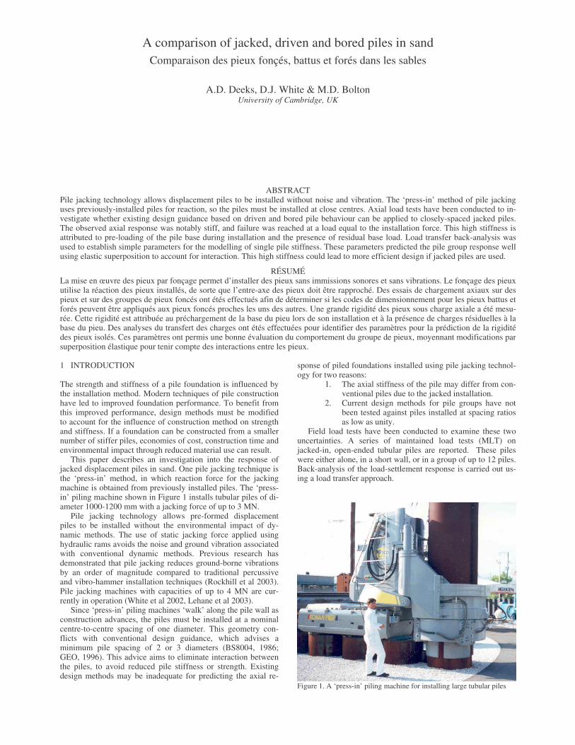
The pile groups were less stiff than the single piles, although 90% of the plunging load was reached before a settlement of 10 mm (10% D), even for the group of 12 piles (Fig. 5). A group strength efficiency, ζstrength (Equation 1), close to unity is appar-ent in every case, indicating that each pile re-mobilises the in-stallation force of the first pile, Qinstall, when failed.
install
groupstrength nQ
Q=ζ (1)
Comparison of the single pile and pile groups is hampered by the variation in pile strength evident from the installation force (Fig. 3). To eliminate this variability in the RATZ back-analyses of the pile groups, the qc profile has been scaled in proportion to the ratio of Qinstall for the first pile in each group and for the single pile. Since τsf and qbf are proportional qc in the MTD design approach (which gave good predictions of the sin-gle pile capacity), this scaling accounts for variability between the tests in a simple manner. The scaling of qc, and the inclusion of group interaction factors are the only differences between the RATZ analyses for the single piles and the pile groups.
The pile group RATZ analyses agree well with the measured response at typical working loads (<50% of the plunging load) (Fig. 5). These reasonable predictions of group settlement by applying a simple interaction factor approach to single pile load test results indicate that a spacing ratio of unity may not pre-clude the application of current simple design approaches.
The stiffness of the 12-pile group is over-predicted at high loads, possibly due to a different failure mechanism acting. The block of enclosed soil was observed to move downwards during failure, in the manner of a plug within a tubular pile.
5 DISCUSSION: STIFFNESS OF CONVENTIONAL PILES
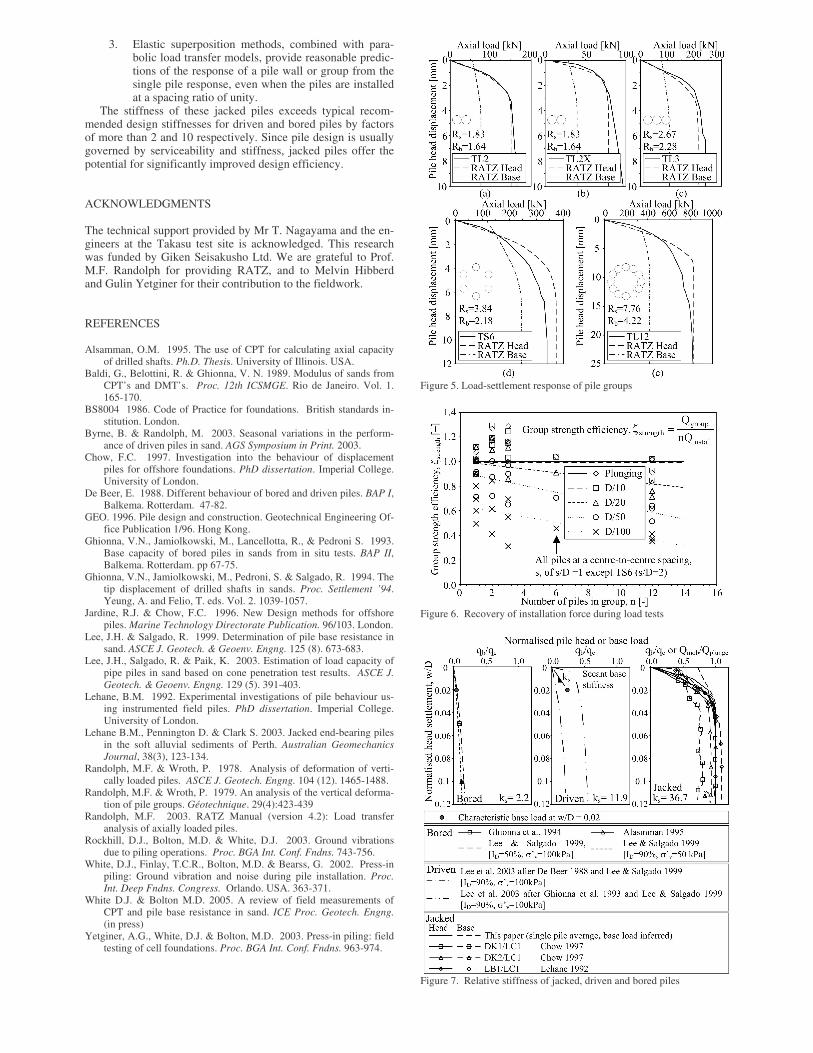
The results from this investigation are summarised on Figure 6. Also shown are additional load test results for 100 mm diameter piles previously conducted at the same site (Yetginer et al 2003). All single piles recovered the jacking force from the final installation stroke when load tested. The groups of n piles re-covered n times the installation force of the first pile, also at a low settlement, despite the spacing ratio of unity.
The stiffness of these jacked piles is considerably higher than conventional driven or bored piles. Existing guidance for the design of bored and driven piles is collated in Figure 7 and compared with the jacked pile results from this investigation and existing published data. The characteristic secant base stiff-ness, ks, of the jacked piles at a settlement of 2% D is more than 2 and 10 times greater than recommended design values for driven and bored piles respectively.
It should be noted that in practice, tension cycles are applied to jacked piles that are installed using the type of machine shown in Figure 1, when each pile acts to provide reaction force. These cycles may eliminate any residual base load, and reduce the resulting head stiffness.
6 CONCLUSIONS
A series of field tests has been conducted on jacked piles and pile groups installed in sand. Axial load tests showed a stiff load-settlement response. The single piles reached plunging failure at a settlement of 3 mm (3% D). The groups of n piles reached 90% of plunging capacity (a load equal to n times the installation force of the first pile in the group) at a settlement of 10 mm (10% D) or less.
The load-settlement response of the single piles was well predicted by load-transfer analysis using parabolic τs-z and qb-z models. The axial response of the pile groups was well pre-dicted by modifying the single pile analysis using interaction factors based on elastic superposition. However, where the pile group comprised a closed cell, the stiffness was over-predicted and the pile cell and enclosed soil failed in unison.
If these observations are confirmed for a wider range of pile dimensions and ground conditions, the implications for the de-sign of jacked piles in sand are that:
1. The measured jacking force during installation indi-cates the plunging capacity of the pile.
2. Jacked piles have a high base stiffness, due to the pre-loading of the soil below the base during installation, and the presence of residual base load.
3. Elastic superposition methods, combined with para-bolic load transfer models, provide reasonable predic-tions of the response of a pile wall or group from the single pile response, even when the piles are installed at a spacing ratio of unity.
The stiffness of these jacked piles exceeds typical recom-mended design stiffnesses for driven and bored piles by factors of more than 2 and 10 respectively. Since pile design is usually governed by serviceability and stiffness, jacked piles offer the potential for significantly improved design efficiency.
ACKNOWLEDGMENTS
The technical support provided by Mr T. Nagayama and the en-gineers at the Takasu test site is acknowledged. This research was funded by Giken Seisakusho Ltd. We are grateful to Prof. M.F. Randolph for providing RATZ, and to Melvin Hibberd and Gulin Yetginer for their contribution to the fieldwork.
REFERENCES
Alsamman, O.M. 1995. The use of CPT for calculating axial capacity of drilled shafts. Ph.D. Thesis. University of Illinois. USA.
Baldi, G., Belottini, R. & Ghionna, V. N. 1989. Modulus of sands from CPT’s and DMT’s. Proc. 12th ICSMGE. Rio de Janeiro. Vol. 1. 165-170.
BS8004 1986. Code of Practice for foundations. British standards in-stitution. London.
Byrne, B. & Randolph, M. 2003. Seasonal variations in the perform-ance of driven piles in sand. AGS Symposium in Print. 2003.
Chow, F.C. 1997. Investigation into the behaviour of displacement piles for offshore foundations. PhD dissertation. Imperial College. University of London.
De Beer, E. 1988. Different behaviour of bored and driven piles. BAP I, Balkema. Rotterdam. 47-82.
GEO. 1996. Pile design and construction. Geotechnical Engineering Of-fice Publication 1/96. Hong Kong.
Ghionna, V.N., Jamiolkowski, M., Lancellotta, R., & Pedroni S. 1993. Base capacity of bored piles in sands from in situ tests. BAP II, Balkema. Rotterdam. pp 67-75.
Ghionna, V.N., Jamiolkowski, M., Pedroni, S. & Salgado, R. 1994. The tip displacement of drilled shafts in sands. Proc. Settlement ’94. Yeung, A. and Felio, T. eds. Vol. 2. 1039-1057.
Jardine, R.J. & Chow, F.C. 1996. New Design methods for offshore piles. Marine Technology Directorate Publication. 96/103. London.
Lee, J.H. & Salgado, R. 1999. Determination of pile base resistance in sand. ASCE J. Geotech. & Geoenv. Engng. 125 (8). 673-683.
Lee, J.H., Salgado, R. & Paik, K. 2003. Estimation of load capacity of pipe piles in sand based on cone penetration test results. ASCE J. Geotech. & Geoenv. Engng. 129 (5). 391-403.
Lehane, B.M. 1992. Experimental investigations of pile behaviour us-ing instrumented field piles. PhD dissertation. Imperial College. University of London.
Lehane B.M., Pennington D. & Clark S. 2003. Jacked end-bearing piles in the soft alluvial sediments of Perth. Australian Geomechanics Journal, 38(3), 123-134.
Randolph, M.F. & Wroth, P. 1978. Analysis of deformation of verti-cally loaded piles. ASCE J. Geotech. Engng. 104 (12). 1465-1488.
Randolph, M.F. & Wroth, P. 1979. An analysis of the vertical deforma-tion of pile groups. Géotechnique. 29(4):423-439
Randolph, M.F. 2003. RATZ Manual (version 4.2): Load transfer analysis of axially loaded piles.
Rockhill, D.J., Bolton, M.D. & White, D.J. 2003. Ground vibrations due to piling operations. Proc. BGA Int. Conf. Fndns. 743-756.
White, D.J., Finlay, T.C.R., Bolton, M.D. & Bearss, G. 2002. Press-in piling: Ground vibration and noise during pile installation. Proc. Int. Deep Fndns. Congress. Orlando. USA. 363-371.
White D.J. & Bolton M.D. 2005. A review of field measurements of CPT and pile base resistance in sand. ICE Proc. Geotech. Engng. (in press)
Yetginer, A.G., White, D.J. & Bolton, M.D. 2003. Press-in piling: field testing of cell foundations. Proc. BGA Int. Conf. Fndns. 963-974.
Figure 5. Load-settlement response of pile groups
Figure 6. Recovery of installation force during load tests
Figure 7. Relative stiffness of jacked, driven and bored piles