Compaction of upstream construction tailings dam beaches...
7
Compaction of upstream construction tailings dam beaches using dozers Scott Martens, Tyler Lappin Klohn Crippen Berger Ltd., Calgary, Alberta Rod Godwaldt Albian Sands Energy Inc., Fort McMurray, Alberta ABSTRACT Upstream construction tailings dams in the oilsands mining industry rely on a compacted shell and beaches of non- liquefiable sand to contain the pond and internal loose beach deposits. Compaction energy to densify the sand in the shell is provided by dozers which densify the sand through the vibration of trafficking repeatedly across the sand surface, together with the downward drainage of construction water through the sand. A trial was performed on a loose beach deposit at the Muskeg River Mine site to assess the level of effort required to densify the sand using CAT D7 dozers, and the vertical extent of compaction. It was found that given sufficient packing effort, the dozers were capable of consistently densifying the sand to a depth of 4 m to 5 m below the beach surface. The effectiveness of the densification was assessed using cone penetration testing, surveys of the surface settlement, and visual observations of water liberated from the beach. RÉSUMÉ Les digues à rejets en amont dans l'industrie du sable bitumineux utilisent une coquille compactée et des rivages de sable non liquéfié pour contenir le bassin et les résidus internes du rivage. L'énergie de compactage pour densifier le sable de la coquille est fournie par des bouteurs qui densifient le sable par vibration en parcourant de façon répétitive l'étendue de sable, en plus d'un drainage de haut en bas des effluents. Un essai a été mené sur un rivage de résidus au site de Muskeg River Mine afin d'évaluer la pression nécessaire pour densifier le sable avec des bouteurs CAT D7, et pour mesurer la portée verticale du compactage. Les résultats ont montré qu'avec une pression suffisante, les bouteurs étaient en mesure de densifier le sable à une profondeur de 4 à 5 m sous la surface du rivage. L'efficacité de la densification a été évaluée par un essai de pénétration au cône, par des levés de surface (tassement) et des observations visuelles de l'eau évacuée par le rivage. 1 INTRODUCTION The Albian Sands Energy (ASE) Muskeg River Mine (MRM) is an oilsands mine 60 km north of Ft. McMurray, Alberta. Tailings from the bitumen extraction process are currently stored in the External Tailings Facility (ETF), a tailings impoundment contained by a ring dyke with a perimeter length of about 12 km. For the majority of that distance, containment is provided by an upstream construction tailings dyke. Tailings placement is ongoing in the ETF, and the ultimate height of the dyke will be a maximum of about 60 m. Upstream construction tailings dams in the oilsands mining industry rely on a compacted shell of coarse tailings sand and beaches of non-liquefiable sand to contain the pond and internal loose beach deposits. A typical section illustrating the zonation of an upstream construction oilsand tailings dyke is shown on Figure 1. Compaction energy to densify the sand in the shell is provided by dozers which compact the sand through the vibration of trafficking repeatedly across the sand surface, together with the downward drainage of construction water through the sand. A trial was performed on a loose beach deposit at the ETF site to assess the level of effort required to densify the sand using CAT D7 dozers, and the vertical extent of compaction. The effectiveness of the densification was assessed using cone penetration testing, surveys of the surface settlement, and visual observations of water liberated from the beach. Figure 1. Upstream construction oilsand tailings dyke – typical section GeoEdmonton'08/GéoEdmonton2008 746
Transcript of Compaction of upstream construction tailings dam beaches...

Compaction of upstream construction tailings dam beaches using dozers Scott Martens, Tyler Lappin Klohn Crippen Berger Ltd., Calgary, Alberta Rod Godwaldt Albian Sands Energy Inc., Fort McMurray, Alberta ABSTRACT Upstream construction tailings dams in the oilsands mining industry rely on a compacted shell and beaches of non-liquefiable sand to contain the pond and internal loose beach deposits. Compaction energy to densify the sand in the shell is provided by dozers which densify the sand through the vibration of trafficking repeatedly across the sand surface, together with the downward drainage of construction water through the sand. A trial was performed on a loose beach deposit at the Muskeg River Mine site to assess the level of effort required to densify the sand using CAT D7 dozers, and the vertical extent of compaction. It was found that given sufficient packing effort, the dozers were capable of consistently densifying the sand to a depth of 4 m to 5 m below the beach surface. The effectiveness of the densification was assessed using cone penetration testing, surveys of the surface settlement, and visual observations of water liberated from the beach. RÉSUMÉ Les digues à rejets en amont dans l'industrie du sable bitumineux utilisent une coquille compactée et des rivages de sable non liquéfié pour contenir le bassin et les résidus internes du rivage. L'énergie de compactage pour densifier le sable de la coquille est fournie par des bouteurs qui densifient le sable par vibration en parcourant de façon répétitive l'étendue de sable, en plus d'un drainage de haut en bas des effluents. Un essai a été mené sur un rivage de résidus au site de Muskeg River Mine afin d'évaluer la pression nécessaire pour densifier le sable avec des bouteurs CAT D7, et pour mesurer la portée verticale du compactage. Les résultats ont montré qu'avec une pression suffisante, les bouteurs étaient en mesure de densifier le sable à une profondeur de 4 à 5 m sous la surface du rivage. L'efficacité de la densification a été évaluée par un essai de pénétration au cône, par des levés de surface (tassement) et des observations visuelles de l'eau évacuée par le rivage. 1 INTRODUCTION The Albian Sands Energy (ASE) Muskeg River Mine (MRM) is an oilsands mine 60 km north of Ft. McMurray, Alberta. Tailings from the bitumen extraction process are currently stored in the External Tailings Facility (ETF), a tailings impoundment contained by a ring dyke with a perimeter length of about 12 km. For the majority of that distance, containment is provided by an upstream construction tailings dyke. Tailings placement is ongoing in the ETF, and the ultimate height of the dyke will be a maximum of about 60 m. Upstream construction tailings dams in the oilsands mining industry rely on a compacted shell of coarse tailings sand and beaches of non-liquefiable sand to contain the pond and internal loose beach deposits. A typical section illustrating the zonation of an upstream construction oilsand tailings dyke is shown on Figure 1. Compaction energy to densify the sand in the shell is provided by dozers which compact the sand through the vibration of trafficking repeatedly across the sand surface, together with the downward drainage of construction water through the sand. A trial was performed on a loose beach deposit at the ETF site to assess the level of effort required to densify the sand using CAT D7 dozers, and the vertical extent of compaction. The effectiveness of the densification was
assessed using cone penetration testing, surveys of the surface settlement, and visual observations of water liberated from the beach.
Figure 1. Upstream construction oilsand tailings dyke – typical section
GeoEdmonton'08/GéoEdmonton2008
746
2 TRIAL SITE The track-packing trial site location was determined in the field by ASE and KCBL representatives. Figure 2 illustrates the region of the ETF chosen for the track-packing trial. This area of the ETF beach was chosen based on the following:
• The beach was greater than 100 m in this area;
• The beach was generally smooth and accessible; and,
• The trial area elevation was sufficiently greater
than the pond to allow for post track-packing subsidence.
Figure 2. Plan of the MRM ETF with track packing trial site 3 TRIAL METHODOLOGY 3.1 Previous Track Packing Experience Outside of the trial environment, beach dozer track-packing was undertaken in selected areas by stepping onto the beach from the upstream dyke cell crest. Dozer track-packing is usually completed by traveling approximately in a line perpendicular to the upstream cell crest outline. Dozers always travel facing the pond (blade
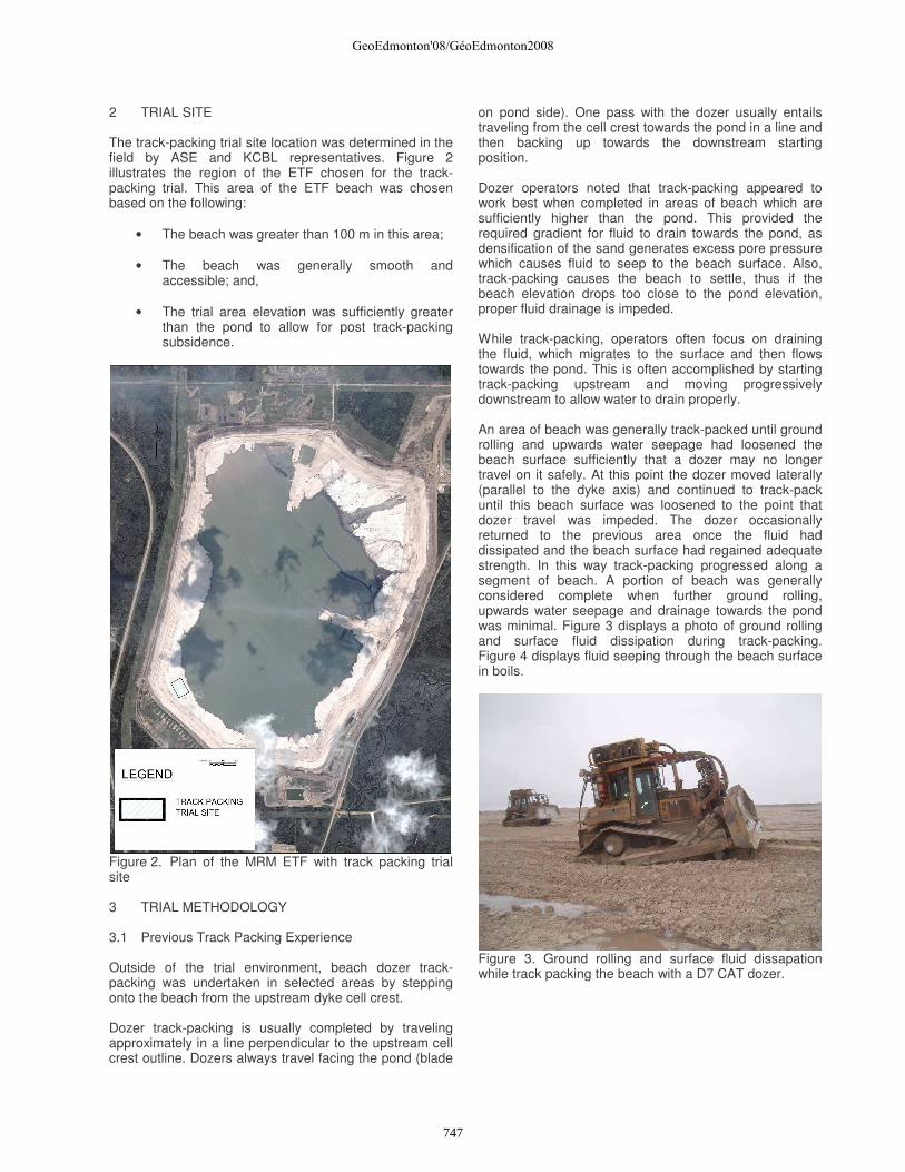
on pond side). One pass with the dozer usually entails traveling from the cell crest towards the pond in a line and then backing up towards the downstream starting position. Dozer operators noted that track-packing appeared to work best when completed in areas of beach which are sufficiently higher than the pond. This provided the required gradient for fluid to drain towards the pond, as densification of the sand generates excess pore pressure which causes fluid to seep to the beach surface. Also, track-packing causes the beach to settle, thus if the beach elevation drops too close to the pond elevation, proper fluid drainage is impeded. While track-packing, operators often focus on draining the fluid, which migrates to the surface and then flows towards the pond. This is often accomplished by starting track-packing upstream and moving progressively downstream to allow water to drain properly. An area of beach was generally track-packed until ground rolling and upwards water seepage had loosened the beach surface sufficiently that a dozer may no longer travel on it safely. At this point the dozer moved laterally (parallel to the dyke axis) and continued to track-pack until this beach surface was loosened to the point that dozer travel was impeded. The dozer occasionally returned to the previous area once the fluid had dissipated and the beach surface had regained adequate strength. In this way track-packing progressed along a segment of beach. A portion of beach was generally considered complete when further ground rolling, upwards water seepage and drainage towards the pond was minimal. Figure 3 displays a photo of ground rolling and surface fluid dissipation during track-packing. Figure 4 displays fluid seeping through the beach surface in boils.
Figure 3. Ground rolling and surface fluid dissapation while track packing the beach with a D7 CAT dozer.
GeoEdmonton'08/GéoEdmonton2008
747

Figure 4. Water liberated from the beach during track packing via fluid boils. 3.2 Trial Procedure The information obtained from observing track packing and discussions with ASE ETF dozer operators was utilized to setup the track-packing grid and establish the degree of track-packing effort to be expended on the trial grid zones. The trial grid was sub-divided into three trial zones; each zone was compacted with a different amount of effort. Although the original program outline suggested that the zones should be compacted with five, ten, and twenty dozer passes, respectively, a modified track-packing approach was developed in the field, utilizing additional site specific information. Testing was executed over an overlapped and centred 6 x 3 grid of CPT locations, as illustrated in Figure 5. The CPT locations were staked in the field based on the beach surface conditions and geometry. The dimensions of the trial grid were approximately 90 m (beach to cell) by 130 m (parallel to cell crest). Track-packing was performed in an area about 20 m larger on each side of the grid, in order to lessen the boundary effects of non-compacted area around it. Figure 6 displays the trial site prior to performing track-packing activities. The trial was completed as follows:
1. CPT testing was completed prior to dozer track-packing to quantify the initial state of the testing area;
2. Dozer track-packing was completed within three
pre-defined zones (A, B, and C, respectively), each at varying levels of track-packing effort;
3. CPT was completed after dozer track-packing to
measure the change in cone resistance and density; and,
4. Further CPT tests were completed after three months to assess potential time dependent effects.
Figure 5. Design layout of track packing trial
Figure 6. Trial area of ETF beach prior to track packing. Photo taken facing the cell crest. Track packing on the trial grid progressed as follows :
• Dozers travelled in a line perpendicular to the dyke axis, from cell to pond while facing the pond;
• Dozers moved along a line once or twice and then moved laterally along an adjacent and parallel line; and,
• Track packing within a trial zone progressed until travel was impeded and the dozers either moved to the adjacent trial zone or waited on the cell crest for the remainder of the track packing cycle.
GeoEdmonton'08/GéoEdmonton2008
748

For the purposes of this trial, a single track-packing cycle has been defined as the process of track-packing a discrete area of beach until fluid migration and ground softening necessitate that the dozer must leave the area until adequate pore pressure dissipation, surface fluid drainage and beach surface strengthening had occurred. As opposed to comparing the effort expended in each trial zone in terms of the number of dozer passes, a trial zone may be defined partially in terms of the number of track-packing cycles completed. 3.3 Track Packing Approach – Zone A If it could be demonstrated that a single track-packing cycle was sufficient to create a consistent depth of dilatant beach tailings, there would be a significant cost savings for ASE in terms of equipment time required. As a result, a single track-packing cycle was completed in Zone A. Zone A was defined as the low effort track-packing area and forms the lower bound for track-packing operation. Within the trial test area, a single track-packing cycle took between 45 minutes and one hour.
3.4 Track Packing Approach – Zone B Zone B was designed as the standard or intermediate track-packing area. This area was track-packed to a level of effort that ASE dozer operators feel is sufficient, thus the standard effort level designation. A standard effort level of compaction may be viewed as the amount of track-packing cycles necessary to reduce ground roll, upward fluid migration and surface drainage to imperceptible quantities. For this trial, in this particular area of ETF beach, a standard or intermediate level of track packing effort was equivalent to 5 track packing cycles. This worked out to be approximately 75% of a day shift because after each track packing cycle it can take some time for the liberated fluid to drain sufficiently so that further track packing can be undertaken. Outside of the trial environment, track packing could proceed on the beach parallel to the dyke axis while fluid dissipation takes place. Dozers would not have to wait at the cell crest while fluid dissipation occurred and could actively be track packing the adjacent beach or performing another task. As a result, track packing trial time estimates are conservative as compared to the time that would be required for operational track packing. Figure 7 displays the extent of water liberated from the beach surface during track packing. 3.5 Track Packing Approach – Zone C Zone C was designated as the extra or high effort track-packing area, to determine what levels of compaction may be achieved with a track-packing effort greater than completed in Zone B.
Figure 7. Extent of water liberated flowing on previously dry beach surface. On day one, five track-packing cycles were completed at Zone C, in order to bring Zone C to similar levels of densification as Zone B. Subsequently, Zone C was allowed to drain for five days before it was track-packed again. On day six, four additional track-packing cycles were completed at Zone C to increase the zone level of compaction beyond that of Zone B. Figure 8 displays Zone C during the second period of track packing.
Figure 8. Tandem D7 dozers track packing Zone C. 4 RESULTS The results of the track-packing trial were compiled by examining the following data sets:
• Comparison of CPT sounding data from before and after track-packing was completed; and,
• Inspection of survey data from before and after track-packing was completed to estimate the ground settlement.
GeoEdmonton'08/GéoEdmonton2008
749
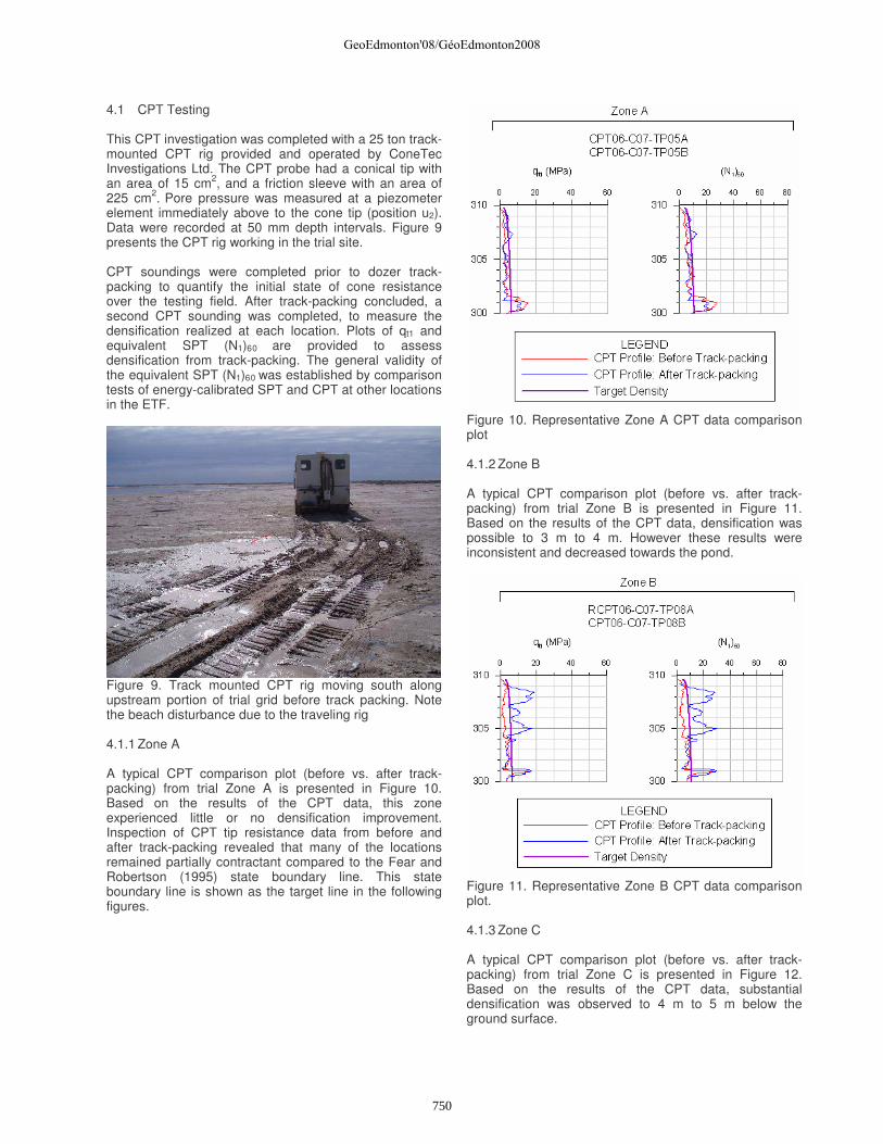
4.1 CPT Testing This CPT investigation was completed with a 25 ton track-mounted CPT rig provided and operated by ConeTec Investigations Ltd. The CPT probe had a conical tip with an area of 15 cm2, and a friction sleeve with an area of 225 cm2. Pore pressure was measured at a piezometer element immediately above to the cone tip (position u2). Data were recorded at 50 mm depth intervals. Figure 9 presents the CPT rig working in the trial site. CPT soundings were completed prior to dozer track-packing to quantify the initial state of cone resistance over the testing field. After track-packing concluded, a second CPT sounding was completed, to measure the densification realized at each location. Plots of qt1 and equivalent SPT (N1)60 are provided to assess densification from track-packing. The general validity of the equivalent SPT (N1)60 was established by comparison tests of energy-calibrated SPT and CPT at other locations in the ETF.
Figure 9. Track mounted CPT rig moving south along upstream portion of trial grid before track packing. Note the beach disturbance due to the traveling rig 4.1.1 Zone A A typical CPT comparison plot (before vs. after track-packing) from trial Zone A is presented in Figure 10. Based on the results of the CPT data, this zone experienced little or no densification improvement. Inspection of CPT tip resistance data from before and after track-packing revealed that many of the locations remained partially contractant compared to the Fear and Robertson (1995) state boundary line. This state boundary line is shown as the target line in the following figures.
Figure 10. Representative Zone A CPT data comparison plot 4.1.2 Zone B A typical CPT comparison plot (before vs. after track-packing) from trial Zone B is presented in Figure 11. Based on the results of the CPT data, densification was possible to 3 m to 4 m. However these results were inconsistent and decreased towards the pond.
Figure 11. Representative Zone B CPT data comparison plot. 4.1.3 Zone C A typical CPT comparison plot (before vs. after track-packing) from trial Zone C is presented in Figure 12. Based on the results of the CPT data, substantial densification was observed to 4 m to 5 m below the ground surface.
GeoEdmonton'08/GéoEdmonton2008
750
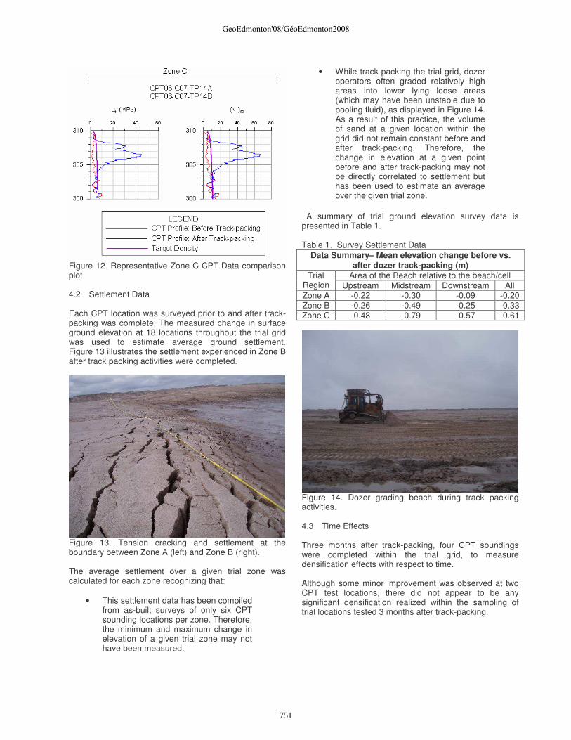
Figure 12. Representative Zone C CPT Data comparison plot 4.2 Settlement Data Each CPT location was surveyed prior to and after track-packing was complete. The measured change in surface ground elevation at 18 locations throughout the trial grid was used to estimate average ground settlement. Figure 13 illustrates the settlement experienced in Zone B after track packing activities were completed.
Figure 13. Tension cracking and settlement at the boundary between Zone A (left) and Zone B (right). The average settlement over a given trial zone was calculated for each zone recognizing that:
• This settlement data has been compiled from as-built surveys of only six CPT sounding locations per zone. Therefore, the minimum and maximum change in elevation of a given trial zone may not have been measured.
• While track-packing the trial grid, dozer operators often graded relatively high areas into lower lying loose areas (which may have been unstable due to pooling fluid), as displayed in Figure 14. As a result of this practice, the volume of sand at a given location within the grid did not remain constant before and after track-packing. Therefore, the change in elevation at a given point before and after track-packing may not be directly correlated to settlement but has been used to estimate an average over the given trial zone.
A summary of trial ground elevation survey data is presented in Table 1. Table 1. Survey Settlement Data
Data Summary– Mean elevation change before vs. after dozer track-packing (m)
Area of the Beach relative to the beach/cell Trial Region Upstream Midstream Downstream All Zone A -0.22 -0.30 -0.09 -0.20 Zone B -0.26 -0.49 -0.25 -0.33 Zone C -0.48 -0.79 -0.57 -0.61
Figure 14. Dozer grading beach during track packing activities. 4.3 Time Effects Three months after track-packing, four CPT soundings were completed within the trial grid, to measure densification effects with respect to time. Although some minor improvement was observed at two CPT test locations, there did not appear to be any significant densification realized within the sampling of trial locations tested 3 months after track-packing.
GeoEdmonton'08/GéoEdmonton2008
751

5 SUMMARY AND CONCLUSIONS A summary of the results of the track-packing trial for Zones A, B, and C, respectively are as follows:
• Zone A – low effort zone:
• Little or no improvement, as measured by CPT
• Average settlement = 0.20 m
• Zone B – intermediate effort zone:
• Improvement in density up to 3 m to 4 m, as measured by CPT, but densification is inconsistent
• Average settlement = 0.33 m
• Zone C – high effort zone:
• Substantial densification possible to 4 m to 5 m, as measured by CPT
• Average settlement = 0.61 m (12%)
It has been shown that given sufficient packing effort, dozers are capable of consistently densifying the sand to a depth of 4 m to 5 m below the beach surface. Systematic densification of upstream construction tailings beaches may allow oil sand mine operators to improve dyke stability while increasing the storage volumes of their impoundments. 6 ACKNOWLEDGEMENTS The authors acknowledge and appreciate Albian Sand Energy Inc’s permission to publish the data and findings in this paper. 7 REFERENCES Fear, C.E., and Robertson, P.K., 1995.” Estimating the Undrained Strength of Sand a Theoretical Framework.” Canadian Geotechnical Journal, 32: 859-870. Klohn Crippen Consultants Ltd., 2005. “Muskeg River Mine External Tailings Facility, Liquefaction Investigation Program – Data Report”. Prepared for Albian Sands Energy Inc., November 2005. Klohn Crippen Berger Ltd., 2006a. “Muskeg River Mine, Ft. McMurray, Geotechnical Issues Related to ETF Expansion.” Letter prepared for Albian Sands Energy Ltd., February 24, 2006. Klohn Crippen Berger Ltd., 2006b. “Testing the Effects of ETF Beach Track-Packing.” Memorandum prepared for Albian Sands Energy Ltd., February 8, 2006.
GeoEdmonton'08/GéoEdmonton2008
752