Compact Torsion Spring (CTS)
12
Leading The Way in Terminal Solutions Worldwide www.opw-es.com OPW Compact Torsion Spring (CTS) Bottom Loading Arms are ideal to replace loading arms in situations where tight clearances are required. The CTS Loader features a fully integrated internal torsion spring for a streamlined profile. Ideal for replacing existing FMC TL Loaders or any application where space is a premium. The CTS has been engineered to be easier to adjust and maintain. Features: Fully Integral Torsion Spring Integral Upward, Downward Travel Stops Carbon Steel/ Aluminum Construction Lo Temp Fluorocarbon Seals Braided Stainless Steel or Rackmaster Composite Hose Available in Left-Hand, Right-Hand, Upfeed, Downfeed Configurations 360° Rotation allows Loading on Both Sides of Loading Bay Removable End cap for Easy Maintenance Benefits: Safe, Easy Spring Adjustment Ideal for Extremely Tight Riser Spacing Horizontal Bearing Module for Added Strength Compact Torsion Spring (CTS)
Transcript of Compact Torsion Spring (CTS)

Leading The Way in Terminal Solutions Worldwide
www.opw-es.com
OPW Compact Torsion Spring (CTS) Bottom Loading Arms are ideal to replace loading arms in situations where tight clearances are required. The CTS Loader features a fully integrated internal torsion spring for a streamlined profile. Ideal for replacing existing FMC TL Loaders or any application where space is a premium.
The CTS has been engineered to be easier to adjust and maintain.
Features: Fully Integral Torsion Spring
Integral Upward, Downward Travel Stops
Carbon Steel/ Aluminum Construction
Lo Temp Fluorocarbon Seals
Braided Stainless Steel or Rackmaster Composite Hose
Available in Left-Hand, Right-Hand, Upfeed, Downfeed Configurations
360° Rotation allows Loading on Both Sides of Loading Bay
Removable End cap for Easy Maintenance
Benefits:
Safe, Easy Spring Adjustment
Ideal for Extremely Tight Riser Spacing
Horizontal Bearing Module for Added Strength
Compact Torsion Spring (CTS)

Leading The Way in Terminal Solutions Worldwide
www.opw-es.com
Specifications
Working Pressure 125 psi 862 kPA
Test Pressure 188 psi 1296 kPA
Operating Temp -20F to 140F -29C to 60C
Up/Down Angular Movement
+45° to -15° From horizontal
Typical Horizontal Spacing
11”
Typical Vertical Spacing
12”
Inlet ANSI 150#
Outlet Tank Truck (TTMA)
Materials of Construction
Base Swivel 1018 Carbon Steel
Swivel Body A356-T6 Aluminum
Swivel Tail A356-T6 Aluminum
Ball Bearings Chrome Steel
Stop Block 1018 Carbon Steel
Spring SAE 5160 Hot Rolled
Compact Torsion Spring (CTS) Swivel
Ordering Guide
CTS50 RH – 04 02 CTS Compact Torsion Swivel Style 50
Orientation RH = Right Hand LH = Left Hand
Inlet Size 04 = 4”
Seal Material 02 = Fluorocarbon

Leading The Way in Terminal Solutions Worldwide
www.opw-es.com
Accessories
Drop Spool 4” Aluminum or Carbon Steel
As Required
Drop Hose 4” Rackmaster Composite 60” OAL, TTMA Flanged Ends 4” Braided Stainless Steel, 60” OAL, TTMA Flanged Ends
L19080 L19081
Coupler Swivel 4” Style 30 (90°) Swivel Joint with Maneuvering Handle TTMA Flanged Ends, Aluminum/ Lo Temp Fluorocarbon
3635FTH-0402
Butterfly Valve 4” Full Flow, Position Locked Butterfly Valve
LBV450VGL
Spacer Spool 4” Loading Arm Coupler Spool, TTMA Flanged ends, Aluminum 6” OAL
VSS4
Sight Glass 4” Acrylic Sight Glass, Tempered, Cast Acrylic
BF4-SG-25
API Coupler 4” API Bottom Loading Coupler Manual Version: Semi-Automatic Version:
1004D3-0402 Lynx852
Compact Torsion Spring (CTS) Hose Loader
Ordering Guide CTS 32 F – 52 – 04 02 – RH
CTS Compact Torsion Swivel
Inlet F = Flanged
Seal Material 02 = Fluorocarbon
Inlet Size 04 = 4”
Feed 32 = Upfeed 33 = Downfeed
Reach 52 = 52” (1321mm) 60 = 60” (1524mm) 70 = 70” (1778mm)
Orientation RH = Right Hand LH = Left Hand
Leading The Way in Terminal Solutions Worldwide
www.opw-es.com
SAFETY PRECAUTIONS
WARNING: Read and understand these instructions before starting installation:
Swivel to be used for its designed purpose only
Local regulations for operation and use must be followed at all times
Although the swivel is designed for higher pressure, proper measures must be taken within the system to allow for thermal expansion
OPW instructions must be followed for installation
Make sure to use adequate personal protection at all times during installation and operation
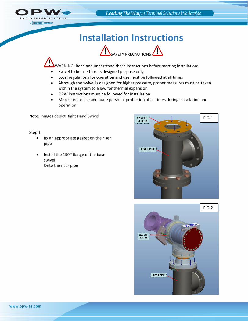
Note: Images depict Right Hand Swivel Step 1:
fix an appropriate gasket on the riser pipe
Install the 150# flange of the base swivel Onto the riser pipe
Installation Instructions
FIG-1
FIG-2

Leading The Way in Terminal Solutions Worldwide
www.opw-es.com
Step 2:
Align the bolt holes
Insert the bolts and tighten the nuts down on the riser flange
Step 3:
Install the Loading Arm Pipe Spool
Install desired accessories
FIG-3
FIG-4

Leading The Way in Terminal Solutions Worldwide
www.opw-es.com
SAFETY PRECAUTIONS
WARNING: Read and understand these instructions before starting adjustment:
Local regulations for operation and use must be followed at all times
OPW instructions must be followed for adjustment
Make sure to use adequate personal protection at all times during operation
Do not attempt to adjust the spring tension while the spring is being loaded by the arm. This can damage the tension shaft and gear
Note: Images depict Right Hand Swivel Tools needed: ¾” socket or wrench Step 1:
Lift the arm so that there is little or no Tension on the spring
Rotate the tension shaft in the direction Indicated on the swivel label to Increase the tension on the spring
Step 2:
Drop the arm slowly and see if the desired Balance is achieved
If not repeat step 1 until desired balance Is achieved
Tension Adjustment Instructions
FIG-5
Leading The Way in Terminal Solutions Worldwide
www.opw-es.com
SAFETY PRECAUTIONS
WARNING: Read and understand these instructions before starting adjustment:
Local regulations for operation and use must be followed at all times
OPW instructions must be followed for disassembly
Make sure to use adequate personal protection at all times during operation
The swivel contains a very strong spring under torsion. Uncontrolled release of the spring can cause personal injury and damage the swivel. The avoid risk follow the instruction sequence
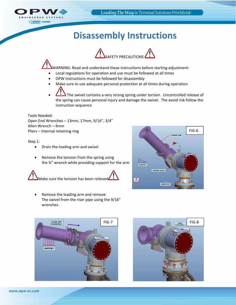
Tools Needed: Open End Wrenches – 13mm, 17mm, 9/16”, 3/4” Allen Wrench – 4mm Pliers – Internal retaining ring Step 1:
Drain the loading arm and swivel
Remove the tension from the spring using the ¾” wrench while providing support for the arm
Make sure the tension has been relieved
Remove the loading arm and remove The swivel from the riser pipe using the 9/16” wrenches
Disassembly Instructions
FIG-6
FIG-7 FIG-8

Leading The Way in Terminal Solutions Worldwide
www.opw-es.com
Step 2:
Remove the 4” diameter CST base swivel module using the 13mm wrench
Remove the PTFE H-block and the two O-ring seals
Step 3:
Remove the ball plugs
Turn the swivel and let the balls fall into a container. A magnet may be necessary to retrieve all of the ball bearings
Note: non-flammable solvent may be used to help loosen the grease and allow easier ball removal
FIG-9
FIG-10
FIG-11

Leading The Way in Terminal Solutions Worldwide
www.opw-es.com
Step 4:
Remove the tail from the body
Remove the environmental seal
Clean the body, tail, and ball bearings while inspecting for any unusual wear or damage
Step 5:
If possible secure the aluminum TTMA flange securely to your work area
Remove the stop block using the 17mm wrench
Step 6:
Hand thread a 3/8-16 bolt into the center of the end plate to use as a temporary handle
Unscrew end plate fasteners using a 4mm Allen wrench or Allen socket
Note: the two screws closest to the tension shaft are a shorter length. Make sure to keep these isolated from the other ones.
FIG-12
FIG-13
FIG-14

Leading The Way in Terminal Solutions Worldwide
www.opw-es.com
Step 7:
Remove the round sector gear Note: this action may require some minor adjusting to find the correct position to let the round gear slide out past the worm gear
Step 8:
Remove the spring Step 9:
Compress the body and tail together
Note: OPW has designed a tool to help with compression which can be seen depicted in the image. If more information on the compression tool is desired please contact OPW engineering
FIG-15
FIG-16
FIG-17
Leading The Way in Terminal Solutions Worldwide
www.opw-es.com
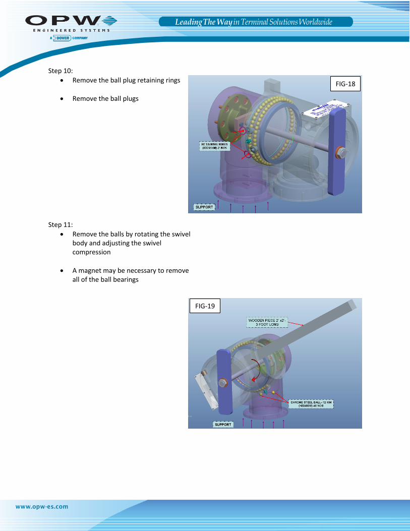
Step 10:
Remove the ball plug retaining rings
Remove the ball plugs Step 11:
Remove the balls by rotating the swivel body and adjusting the swivel compression
A magnet may be necessary to remove all of the ball bearings
FIG-18
FIG-19
Leading The Way in Terminal Solutions Worldwide
www.opw-es.com
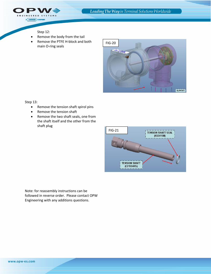
Step 12:
Remove the body from the tail
Remove the PTFE H-block and both main O-ring seals
Step 13:
Remove the tension shaft spirol pins
Remove the tension shaft
Remove the two shaft seals, one from the shaft itself and the other from the shaft plug
Note: for reassembly instructions can be followed in reverse order. Please contact OPW Engineering with any additions questions.
FIG-20
FIG-21


![Mower County transcript. (Lansing, Minn.) 1897-11-17 [p ].€¦ · cts cts cts cts cts cts cts cts cts JACKETS. Ladies' heavy Boucle Jackets, the latest style, and worth $5.00, only](https://static.fdocuments.in/doc/165x107/5fce2fde3593f56f3c130835/mower-county-transcript-lansing-minn-1897-11-17-p-cts-cts-cts-cts-cts-cts.jpg)