COMPACT PRINTED SLOT ANTENNAS FOR Y.-C. Lee · PDF file · 2017-12-17COMPACT...
17
Progress In Electromagnetics Research, PIER 88, 289–305, 2008 COMPACT PRINTED SLOT ANTENNAS FOR WIRELESS DUAL- AND MULTI-BAND OPERATIONS Y.-C. Lee and J.-S. Sun Institute of Computer and Communication Engineering National Taipei University of Technology 1, Sec. 3, Chung-hsiao E. Road, Taipei 10608, Taiwan, R.O.C. Abstract—This paper presents a printed slot antenna using the printed structure in order to improve its dual-band and compact size performances. The printed slot structure is used as additional resonators to produce dual-band operation for covering the worldwide interoperability for microwave access (WiMAX) and the 5.2-GHz wireless local area network (WLAN) bands. In order to achieve wideband and multi-band operation, the slot antennas with a slotted structure and an inverted-L slot structure for covering the wireless communication operations are developed. Finally, we propose a novel and compact printed slot antenna with mixing slot structures to obtain and cover for the 2.4-GHz WLAN (2.4–2.484 GHz), the WiMAX (IEEE 802.16e in the Taiwan: 2.5–2.69/3.5–3.65GHz), and the 5- GHz WLAN (5.15–5.35/5.725–5.825 GHz). Several properties of the proposed antennas for dual- and multi-band characterize radiation performances such as impedance bandwidth and radiation pattern. Measured gain has been confirmed experimentally for the multi-band wireless communication systems. 1. INTRODUCTION Compact design and multi-band operations for the wireless commu- nication strong design advantages in low-profile, easy fabrication, low manufacturing cost, and easy integrating circuit boards. Many com- pact antennas with broadband and multi-band performances including dipole antenna, monopole antenna, and planar antenna configurations have been reported [1–6]. These are printed antennas with moderate radiating characteristics and can be operative at dual- and multiple- frequency bands. Moreover, for the antenna fabrication designs, the
Transcript of COMPACT PRINTED SLOT ANTENNAS FOR Y.-C. Lee · PDF file · 2017-12-17COMPACT...

Progress In Electromagnetics Research, PIER 88, 289–305, 2008
COMPACT PRINTED SLOT ANTENNAS FORWIRELESS DUAL- AND MULTI-BAND OPERATIONS
Y.-C. Lee and J.-S. Sun
Institute of Computer and Communication EngineeringNational Taipei University of Technology1, Sec. 3, Chung-hsiao E. Road, Taipei 10608, Taiwan, R.O.C.
Abstract—This paper presents a printed slot antenna using theprinted structure in order to improve its dual-band and compactsize performances. The printed slot structure is used as additionalresonators to produce dual-band operation for covering the worldwideinteroperability for microwave access (WiMAX) and the 5.2-GHzwireless local area network (WLAN) bands. In order to achievewideband and multi-band operation, the slot antennas with a slottedstructure and an inverted-L slot structure for covering the wirelesscommunication operations are developed. Finally, we propose a noveland compact printed slot antenna with mixing slot structures toobtain and cover for the 2.4-GHz WLAN (2.4–2.484 GHz), the WiMAX(IEEE 802.16e in the Taiwan: 2.5–2.69/3.5–3.65 GHz), and the 5-GHz WLAN (5.15–5.35/5.725–5.825 GHz). Several properties of theproposed antennas for dual- and multi-band characterize radiationperformances such as impedance bandwidth and radiation pattern.Measured gain has been confirmed experimentally for the multi-bandwireless communication systems.
1. INTRODUCTION
Compact design and multi-band operations for the wireless commu-nication strong design advantages in low-profile, easy fabrication, lowmanufacturing cost, and easy integrating circuit boards. Many com-pact antennas with broadband and multi-band performances includingdipole antenna, monopole antenna, and planar antenna configurationshave been reported [1–6]. These are printed antennas with moderateradiating characteristics and can be operative at dual- and multiple-frequency bands. Moreover, for the antenna fabrication designs, the

290 Lee and Sun
slot structures require to provide a broadband and multi-band sys-tems including 2.4- and 5-GHz wireless local area network (WLAN)bands, but without the worldwide interoperability for microwave ac-cess (WiMAX). Recently several interesting designs of the slot anten-nas with diverse geometric configurations for the bandwidth enhance-ment and the size reduction functions have been widely studied [7–12].These antennas based on the slot design configurations and the tunableantenna fabrications have been developed to obtain wide impedancebandwidth and small size, but they have complex designed structure.The designed slot antennas improve multi- and dual-band for the wire-less communication operations [13–24]. The feed point structure of theslot antennas using coplanar waveguide (CPW) fed and microstrip linefed has been developed to integrate the circuit boards over wide- andmulti-bandwidth of the operating bands.
In this paper, first a new compact antenna with the printedslot structure is proposed to achieve the dual-band operation. Theslot structure on the printed antenna that satisfies the requirementsof the mobile-WiMAX and 5.2-GHz WLAN applications such asthe impedance bandwidth, radiation pattern and gain is presented.Second, printed slot antennas are introduced by using a slottedstructure and an inverted-L slot structure, respectively. Theinvestigation numerically and experimentally demonstrates that atunable multi-operating band and an enhancement of the antennabandwidth owing to the proposed antenna with the slot-shapedradiators. Finally, the proposed compact printed slot antenna withthe mixing slot structures is presented and experimented by the wayof arranging with simple configuration and slot configurations that wecould applied to the printed antenna, and a multi-band characteristicwith the proposed antenna improves the narrow band of the compactantenna with a single metal plane for wireless systems applicationsof the 2.4-GHz WLAN (2.4–2.484 GHz), the WiMAX (IEEE 802.16ein the Taiwan: 2.5–2.69/3.5–3.65 GHz) and the 5-GHz WLAN (5.15–5.35/5.725–5.825 GHz).
The paper is organized as follows. As a starting point, Section 2presents the printed slot antenna for dual-band operation and itsradiation performances. After that, design and parameter study ofthe printed slot antennas with a slotted structure and an inverted-Lslot structure are described in Section 3 and the printed slot antennausing mixing slot structure is also created and tested. Finally, thecomplete study is summarized in Section 4.
Progress In Electromagnetics Research, PIER 88, 2008 291
2. DUAL-BAND ANTENNA
2.1. Antenna Design
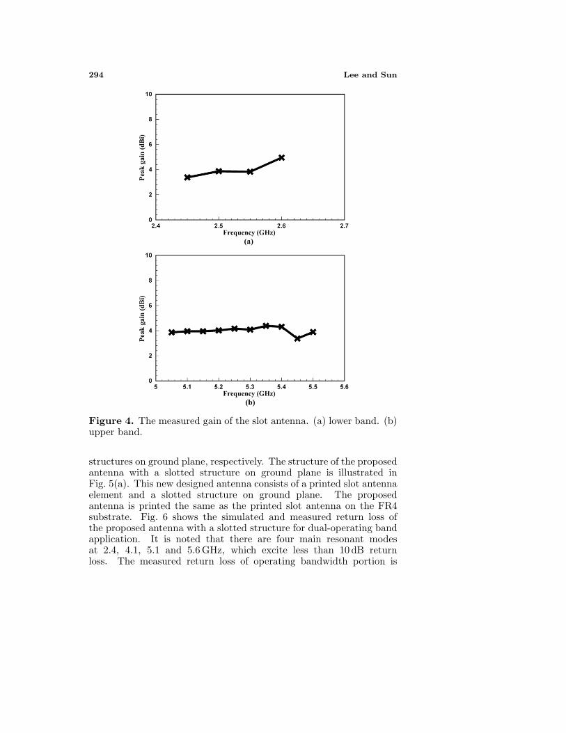
The geometry and configuration of the printed slot antenna for dual-band operation is illustrated in Fig. 1. The compact design of proposedantenna has a slot structure, a rectangular-shaped ground plane andthe fed by a 50 coaxial line that is applied to interface the antennato the test equipment on the selfsame plane. The inner fed conductorand the outer metal sheath of the coaxial line connect to the feed pointand the ground plane, both with a distance of 1.5 mm between twopoints, respectively. The microstrip line with feed point has a matchingconnector of 1.1× 11.5 mm2. The proposed antenna prints on the FR4substrate with a thickness of 0.8 mm, dielectric constant of 4.3, andloss tangent of 0.0245 and has a compact dimension of 34× 15 mm2 inthis study. In this design, the printed slot structure of the proposedantenna can produce two different surface current patches and obtain adual- frequency band. The printed slot structure provides a wide upperresonance mode to cover 5.2-GHz WLAN band, while the right copperpatch and the left rectangular-shaped ground plane obtain the lowerresonance mode including the mobile-WiMAX band. This antennastructure is easy to design and to achieve a stable bandwidth for dual-band wireless operations.
Figure 1. The geometry of the slot antenna.

292 Lee and Sun
2.2. Results
Fig. 2 shows the simulated and measured return loss of the proposedantenna with compact and low profile structures for dual-operatingwireless application. Fig. 2 shows the measured return loss andit is noted that there are two main resonant modes at 2.7 and5.1 GHz, which excite less than 10 dB return loss. The measuredreturn loss of operating bandwidth portion has a 540 MHz between2.48 and 3.02 GHz at the lower resonance mode. Nevertheless, thisresonance bandwidth has the signification operation on the Mobile-WiMAX system in the Taiwan between 2.5 and 2.69 GHz. Theprinted slot structure shows the signification factor on the variationof the upper resonance mode of 1840 MHz within 3.81–5.65 GHz,which cover the 5.2-GHz for WLAN operation (5.15–5.35 GHz). Themeasured bandwidth of the proposed antenna covers two impedancebandwidths, 19.6% on the lower bandwidth for the Mobile-WiMAXsystem and 38.9% on the upper bandwidth for 5.2-GHz WLANsystem, respectively. The results with the return loss and radiationperformances of the proposed slot antennas are measured by an HP8720C vector network analyzer and an NSI far-field chamber. Westudied the new geometry of the proposed antennas by Ansoft HFSSelectromagnetic simulation software.
Figure 2. The measured and simulated return loss of the slot antenna.
The measured radiation patterns of the proposed slot antennaat 2.6 and 5.2 GHz are illustrated in Fig. 3. It is noticed thatthe radiation patterns with two main planes are conventional dipoleantenna. The x-z plane radiation pattern is omni-directional pattern attwo presented operation. So the radiation patterns are generally omni-

Progress In Electromagnetics Research, PIER 88, 2008 293
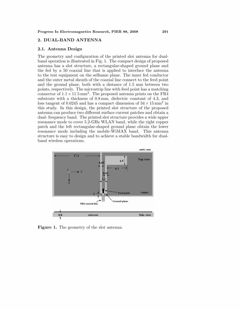
directional over the entire bandwidth, which is similar to a conventionalantenna for wireless communication systems. The peak antenna gainfor frequencies throughout the matching bands for proposed antennawas measured, as shown in Fig. 4. The maximum measured gainsat all radiation planes obtain a 4.95 dBi at 2.6 GHz within the loweroperation band and a steady gain from 4.42 dBi to 3.88 dBi within5–5.5 GHz at the upper operation band.
(a)
(b)
Figure 3. Measured radiation patterns of the slot antenna at x-z andy-z planes. (a) 2.6 GHz. (b) 5.2 GHz.
3. MULTI-BAND ANTENNAS
3.1. Antenna with Slotted Structure
In order to make the antenna achieve multi-band operation for wirelesscommunication systems, we added a slotted and an inverted-L slot
294 Lee and Sun
Figure 4. The measured gain of the slot antenna. (a) lower band. (b)upper band.
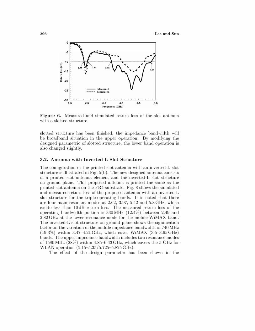
structures on ground plane, respectively. The structure of the proposedantenna with a slotted structure on ground plane is illustrated inFig. 5(a). This new designed antenna consists of a printed slot antennaelement and a slotted structure on ground plane. The proposedantenna is printed the same as the printed slot antenna on the FR4substrate. Fig. 6 shows the simulated and measured return loss ofthe proposed antenna with a slotted structure for dual-operating bandapplication. It is noted that there are four main resonant modesat 2.4, 4.1, 5.1 and 5.6 GHz, which excite less than 10 dB returnloss. The measured return loss of operating bandwidth portion is
Progress In Electromagnetics Research, PIER 88, 2008 295
160 MHz (6.6%) between 2.35 and 2.51 GHz at the lower resonancemode for 2.4-GHz WLAN band. The upper impedance bandwidthincludes three resonance modes of 2300 MHz (45.1%) between 3.95and 6.25 GHz, which covers the 5-GHz for WLAN operation (5.15–5.35/5.725–5.825 GHz).
(a)
(b)
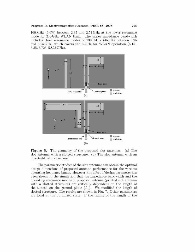
Figure 5. The geometry of the proposed slot antennas. (a) Theslot antenna with a slotted structure. (b) The slot antenna with aninverted-L slot structure.
The parametric studies of the slot antennas can obtain the optimaldesign dimensions of proposed antenna performance for the wirelessoperating frequency bands. However, the effect of design parameter hasbeen shown in the simulation that the impedance bandwidth and theoperating resonance modes of proposed antenna (printed slot antennawith a slotted structure) are critically dependent on the length ofthe slotted on the ground plane (L1). We modified the length ofslotted structure. The results are shown in Fig. 7. Other parametersare fixed at the optimized state. If the tuning of the length of the
296 Lee and Sun
Figure 6. Measured and simulated return loss of the slot antennawith a slotted structure.
slotted structure has been finished, the impedance bandwidth willbe broadband situation in the upper operation. By modifying thedesigned parametric of slotted structure, the lower band operation isalso changed slightly.
3.2. Antenna with Inverted-L Slot Structure
The configuration of the printed slot antenna with an inverted-L slotstructure is illustrated in Fig. 5(b). The new designed antenna consistsof a printed slot antenna element and the inverted-L slot structureon ground plane. This proposed antenna is printed the same as theprinted slot antenna on the FR4 substrate. Fig. 8 shows the simulatedand measured return loss of the proposed antenna with an inverted-Lslot structure for the triple-operating bands. It is noted that thereare four main resonant modes at 2.62, 3.97, 5.42 and 5.8 GHz, whichexcite less than 10 dB return loss. The measured return loss of theoperating bandwidth portion is 330 MHz (12.4%) between 2.49 and2.82 GHz at the lower resonance mode for the mobile-WiMAX band.The inverted-L slot structure on ground plane shows the significationfactor on the variation of the middle impedance bandwidth of 740 MHz(19.3%) within 3.47–4.21 GHz, which cover WiMAX (3.5–3.65 GHz)bands. The upper impedance bandwidth includes two resonance modesof 1580 MHz (28%) within 4.85–6.43 GHz, which covers the 5-GHz forWLAN operation (5.15–5.35/5.725–5.825 GHz).
The effect of the design parameter has been shown in the

Progress In Electromagnetics Research, PIER 88, 2008 297
Figure 7. Simulated return losses with different slotted length (L1)of the slot antenna with a slotted structure.
Figure 8. Measured and simulated return loss of the slot antennawith an inverted-L slot structure.
simulation dependent on the length of the inverted-L slot structureon ground plane (L2). We modified the length of the inverted-L slotstructure. The results are shown in Fig. 9. Other parameters are fixedat the optimized state. If the antenna has confirmed the length ofproposed slot configuration, the performance of resonant mode will addimpedance bandwidth in the middle band. By modifying the lengthsof the slot form, the middle and the upper bands have been changedalso dependent on surface current patches.

298 Lee and Sun
Figure 9. Simulated return losses with different slot length (L2) ofthe slot antenna with an inverted-L slot structure.
3.3. Antenna with Mixing Slot Structure
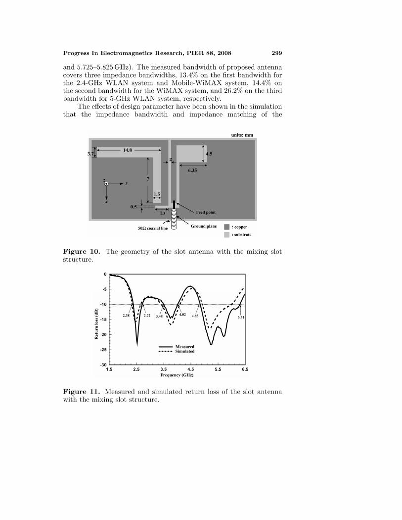
In the foregoing paragraphs slotted and inverted-L slot forms canachieve the dual-band and the multi-band operations at the compactconfiguration for the wireless communication systems. Fig. 10 showsthe geometry of the proposed antenna with mixing slot structure forthe wireless multi-band applications. It is printed on a 0.8 mm FR4substrate and has a compact dimension of 34 × 15 mm2 in this study.The compact design of the proposed antenna has a small slotted form,an inverted-L slot on ground plane and fed by a 50Ω coaxial cableline on the selfsame plane. Moreover, in order to achieve a compactstructure for the proposed antenna, the slot structures on metal planeare designed exactly as shown in Fig. 10.
Fig. 11 shows the simulated and measured return loss of theproposed antenna with compact and mixing slot structures for themulti-band wireless communication applications. The measured returnloss of operation bandwidth portion is 340 MHz between 2.38–2.72 GHzat the first resonance mode. Nevertheless, this resonance bandwidthhas the signification operation on the 2.4-GHz WLAN system between2.4 and 2.484 GHz and the Mobile-WiMAX system in Taiwan between2.5 and 2.69 GHz. However, it shows the signification factor on thevariation of the second resonance mode of 540 MHz between 3.48–4.02 GHz, which cover the WiMAX (3.5–3.65 GHz) bands. The twohigher resonance modes exhibit bandwidth of 1460 MHz from 4.85 GHzto 6.31 GHz, covering the 5-GHz for WLAN operation (5.15–5.35 GHz
Progress In Electromagnetics Research, PIER 88, 2008 299
and 5.725–5.825 GHz). The measured bandwidth of proposed antennacovers three impedance bandwidths, 13.4% on the first bandwidth forthe 2.4-GHz WLAN system and Mobile-WiMAX system, 14.4% onthe second bandwidth for the WiMAX system, and 26.2% on the thirdbandwidth for 5-GHz WLAN system, respectively.
The effects of design parameter have been shown in the simulationthat the impedance bandwidth and impedance matching of the
Figure 10. The geometry of the slot antenna with the mixing slotstructure.
Figure 11. Measured and simulated return loss of the slot antennawith the mixing slot structure.

300 Lee and Sun
proposed antenna are critically dependent on the length of a slottedstructure (L3). We modified the length of slot form. The results areshown in Fig. 12. Other parameters are fixed at the optimized state.Its main effect is to match all the operating frequency bandwidth. Ifthe antenna has completed the length of slotted form, the performanceof impedance bandwidth will be broadband situation in all operatingbands.
Figure 12. Simulated return losses with different slot length (L3) ofthe slot antenna with the mixing slot structure.
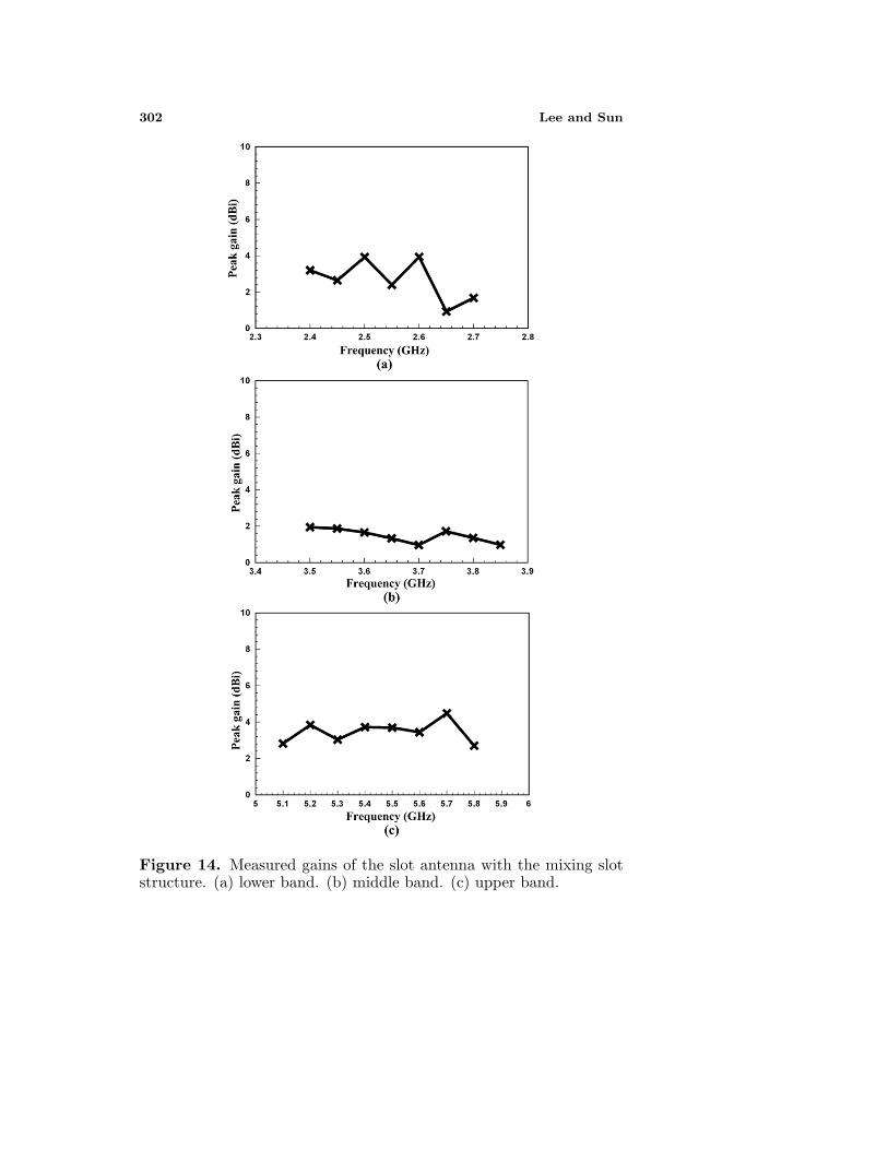
The measured radiation patterns of the proposed antenna at2.45 GHz, 3.6 GHz, and 5.8 GHz are illustrated in Fig. 13. It isnoted that the radiation patterns in two main planes at the wirelesscommunication operations are conventional dipole antenna of the same.The x-z plane radiation pattern is omni-directional pattern at threepresented operations. So the radiation patterns are generally omni-directional over the entire bandwidth, similar to a conventional antennafor wireless communication systems. The peak antenna gain forfrequencies throughout the matching bands for proposed antenna wasmeasured, as shown in Fig. 14. The variation ranges of maximummeasured gain at all radiation planes are varied from 3.9 dBi to1.06 dBi within 2.4–2.7 GHz at the first operating frequency band,from 1.95 dBi to 0.97 dBi within 3.5–3.9 GHz at the second operatingfrequency band and from 4.48 dBi to 2.82 dBi within 5.1–5.9 GHz at thethird operating frequency band, respectively. The measured results ofproposed antenna not only have multi-band effect but also reach theoperating applications of the wireless communication systems.

Progress In Electromagnetics Research, PIER 88, 2008 301
(a)
(b)
(c)
Figure 13. Measured radiation patterns of the slot antenna with themixing slot structure at x-z and y-z planes. (a) 2.45 GHz. (b) 3.6 GHz.(c) 5.8 GHz.
302 Lee and Sun
Figure 14. Measured gains of the slot antenna with the mixing slotstructure. (a) lower band. (b) middle band. (c) upper band.

Progress In Electromagnetics Research, PIER 88, 2008 303
4. CONCLUSION
New printed compact slot antennas have been developed and canachieve the dual-band and the multi-band wireless communicationoperations by using the manifold slot structures including the printedslot, the slotted form and inverted-L slot. The experimental resultsof the slots on the metal plane in the printed compact antennamake a strong effect on the antenna’s operating resonance modes andimpedance bandwidth, so the characteristics of compact antennas withthe slot configurations are improved and verified. Experimental resultsshow that by using proposed designs and tuning their dimensions,operating bandwidth, measured gain and radiation patterns can beobtained for 2.4- and 5-GHz WLAN/WiMAX applications.
REFERENCES
1. Hwang, S. H., J. I. Moon, W. I. Kwak, and S. O. Park,“Printed compact dual band antenna for 2.4 and 5 GHz ISM bandapplications,” IEE Electronic Letters, Vol. 40, No. 25, 1568–1569,2004.
2. Liu, W.-C. and H.-J. Liu, “Compact triple-band slotted monopoleantenna with asymmetrical CPW grounds,” IEE ElectronicLetters, Vol. 42, No. 15, 840–842, 2006.
3. Si, L.-M. and X. Lv, “CPW-fed multi-band omni-directional pla-nar microstrip antenna using composite metamaterial resonatorsfor wireless communications,” Progress In Electromagnetics Re-search, PIER 83, 133–146, 2008.
4. Yin, X.-C., C.-L. Ruan, S.-G. Mo, C.-Y. Ding, and J.-H. Chu,“A compact ultra-wideband microstrip antenna with multiplenotches,” Progress In Electromagnetics Research, PIER 84, 321–332, 2008.
5. Li, J.-Y. and Y.-B. Gan, “Multi-band characteristic of open sleeveantenna,” Progress In Electromagnetics Research, PIER 58, 135–148, 2006.
6. Deepu, V., K. R. Rohith, J. Manoj, M. N. Suma, K. Vasudevan,C. K. Aanandan, and P. Mohanan, “Compact uniplanar antennafor WLAN applications,” IEE Electronic Letters, Vol. 43, No. 2,70–72, 2007.
7. Behdad, N. and K. Sarabandi, “Bandwidth enhancement andfurther size reduction of a class of miniaturized slot antennas,”IEEE Trans. Antennas Propag., Vol. 52, No. 8, 1928–1935, Aug.2004.

304 Lee and Sun
8. Chen, W.-S. and K.-Y. Ku, “Band-rejected design of the printedopen slot antenna for WLAN/WiMAX operation,” IEEE Trans.Antennas Propag., Vol. 56, No. 4, 1163–1169, Apr. 2008.
9. Khodaei, G. F., J. Nourinia, and C. Ghobadi, “A practicalminiaturized U-slot patch antenna with enhanced bandwidth,”Progress In Electromagnetics Research B, Vol. 3, 47–62, 2008.
10. Latif, S. I., L. Shafai, and S. K. Sharma, “Bandwidth enhancementand size reduction of microstrip slot antennas,” IEEE Trans.Antennas Propag., Vol. 53, No. 3, 994–1003, Mar. 2005.
11. Abdelaziz, A. A., “Bandwidth enhancement of microstripantenna,” Progress In Electromagnetics Research, PIER 63, 311–317, 2006.
12. Jan, J.-Y. and J.-W. Su, “Bandwidth enhancement of a printedwide-slot antenna with a rotated slot,” IEEE Trans. AntennasPropag., Vol. 53, No. 6, 2111–2114, Jun. 2005.
13. Wang, C.-J. and S.-W. Chang, “Studies on dual-band multi-slotantennas,” Progress In Electromagnetics Research, PIER 83, 293–306, 2008.
14. Song, Y., Y.-C. Jiao, G. Zhao, and F.-S. Zhang, “MultibandCPW-fed triangle-shaped monopole antenna for wireless applica-tions,” Progress In Electromagnetics Research, PIER 70, 329–336,2007.
15. Rhee, S. and G. Yun, “CPW fed slot antenna for triple-frequencyband operation,” IEE Electronic Letters, Vol. 42, No. 17, 952–953,2006.
16. Chair, R., A. A. Kishk, and K. F. Lee, “Ultrawide-band coplanarwaveguide-fed rectangular slot antenna,” IEEE Antennas WirelessPropag. Lett., Vol. 3, 227–229, 2004.
17. Chen, S.-Y., P.-H. Wang, and P. Hsu, “Uniplanar log-periodic slotantenna fed by a CPW for UWB applications,” IEEE AntennasWireless Propag. Lett., Vol. 5, 256–259, 2006.
18. Ren, W., “Compact dual-band slot antenna for 2.4/5 GHz WLANapplications,” Progress In Electromagnetics Research B, Vol. 8,319–327, 2008.
19. Eldek, A. A., A. Z. Elsherbeni, and C. E. Smith, “Dual-wideband square slot antenna with a U-shaped printed tuningstub for personal wireless communication systems,” Progress InElectromagnetics Research, PIER 53, 319–333, 2005.
20. Chen, S.-Y. and P. Hsu, “Broad-band radial slot antenna fed bycoplanar waveguide for dual-frequency operation,” IEEE Trans.Antennas Propag., Vol. 53, No. 11, 3448–3452, Nov. 2005.

Progress In Electromagnetics Research, PIER 88, 2008 305
21. Wang, C.-J., J.-J. Lee, and R.-B. Huang, “Experimental studiesof a miniaturized CPW-fed slot antenna with the dual-frequencyoperation,” IEEE Antennas Wireless Propag. Lett., Vol. 2, 151–154, 2003.
22. Chen, J.-S., “Dual-frequency annular-ring slot antenna fed byCPW feed and microstrip line feed,” IEEE Trans. AntennasPropag., Vol. 53, No. 1, 569–571, Jan. 2005.
23. Wu, J.-W., H.-M. Hsiao, J.-H. Lu, and S.-H. Chang, “Dualbroadband design of rectangular slot antenna for 2.4 and 5 GHzwireless communication,” IEE Electronic Letters, Vol. 40, No. 23,1461–1463, 2004.
24. Sze, J.-Y., C.-I. G. Hsu, and S.-C. Hsu, “Design of a compactdual-band annular-ring slot antenna,” IEEE Antennas WirelessPropag. Lett., Vol. 6, 423–426, 2007.