Compact HMI 800 - ABB Group 9 This Product Guide is primarily intended to provide sales...
98
Industrial IT Compact HMI 800 System Version 4.1 Product Guide
Transcript of Compact HMI 800 - ABB Group 9 This Product Guide is primarily intended to provide sales...

IndustrialITCompact HMI 800
System Version 4.1
Product Guide
ProductGuideSV4.book Page 1 Tuesday, May 20, 2008 1:47 PM

ProductGuideSV4.book Page 2 Tuesday, May 20, 2008 1:47 PM

IndustrialITCompact HMI 800
System Version 4.1
Product Guide
ProductGuideSV4.book Page 3 Tuesday, May 20, 2008 1:47 PM

NOTICEThe information in this document is subject to change without notice and should not beconstrued as a commitment by ABB. ABB assumes no responsibility for any errors thatmay appear in this document.
In no event shall ABB be liable for direct, indirect, special, incidental or consequentialdamages of any nature or kind arising from the use of this document, nor shall ABB beliable for incidental or consequential damages arising from use of any software or hard-ware described in this document.
This document and parts thereof must not be reproduced or copied without written per-mission from ABB, and the contents thereof must not be imparted to a third party nor usedfor any unauthorized purpose.
The software or hardware described in this document is furnished under a license andmay be used, copied, or disclosed only in accordance with the terms of such license.
This product meets the requirements specified in EMC Directive 89/336/EEC and in LowVoltage Directive 72/23/EEC.
Copyright © 2005-2008 by ABB. All rights reserved.
Release: October 2005Revised: February 2008Document number: 3BSE041037R4201/F
TRADEMARKSAll rights to trademarks reside with their respective owners.
ProductGuideSV4.book Page 4 Tuesday, May 20, 2008 1:47 PM

ProductGuideSV4.book Page 5 Tuesday, May 20, 2008 1:47 PM
TABLE OF CONTENTS
Section 1 - IntroductionWelcome ............................................................................................................................9
Intended Use of This Book................................................................................................9
Target Group ..........................................................................................................9
Industrial IT Compact HMI 800 ............................................................................9
Purpose, Scope and Intended Use ........................................................................11
Aspect Objects Architecture............................................................................................11
Terminology.....................................................................................................................13
Applicable Standards and Specifications ........................................................................16
Related Product Guides and Release Notes.....................................................................18
Section 2 - Key BenefitsFeatures and Benefits ...........................................................................................19
Reducing Time to Decision and Action ...............................................................20
Engineering for Maximum Performance .............................................................21
Integration of Installed Systems...........................................................................22
Section 3 - Compact HMI 800Compact HMI 800 Overview ..........................................................................................23
Core System.....................................................................................................................24
Plant Explorer.......................................................................................................24
Alarm and Event ..................................................................................................27
Trend Logs ...........................................................................................................30
Security .............................................................................................................30
Clock synchronization of Workplaces..................................................................31
Export and Import of Application Data ...............................................................33
PLC Connect ........................................................................................................33
3BSE041037R4201/F 5

ProductGuideSV4.book Page 6 Tuesday, May 20, 2008 1:47 PM
System Options................................................................................................................34
FDA 21 CFR Part 11 Support ..............................................................................34
Authorization - User Re-authentication and Double Authentication ...................36
Access Control .....................................................................................................36
Electronic Signature - Digital Signature ..............................................................36
Audit Trail ............................................................................................................36
SMS and e-mail Messaging .................................................................................38
Calculation Engine ...............................................................................................40
Section 4 - OperationsOverview .........................................................................................................................43
Operator Workplace Client ..............................................................................................43
Layout options......................................................................................................44
Faceplates .............................................................................................................45
Display Call-up ....................................................................................................47
Navigation ............................................................................................................48
Hot Keys .............................................................................................................49
Alarm List ............................................................................................................49
Event List .............................................................................................................50
Trend Display .......................................................................................................50
Group Display ......................................................................................................52
Log over .............................................................................................................53
Section 5 - EngineeringOverview .........................................................................................................................55
Engineering Workplace ...................................................................................................55
Engineering Platform including Bulk Data Manager...........................................55
Graphics Builder ..................................................................................................56
Section 6 - Communication NetworkThe Industrial IT Network Architecture..........................................................................59
Overview .............................................................................................................59
Industrial IT Network Security Considerations ...................................................61
3BSE041037R4201/F 6

ProductGuideSV4.book Page 7 Tuesday, May 20, 2008 1:47 PM
Firewall .............................................................................................................61
Virus Risks ...........................................................................................................63
Domains .............................................................................................................63
System Servers ................................................................................................................64
Communication Hardware...............................................................................................64
Switches and Routers ...........................................................................................64
Network Cables ....................................................................................................66
Network Performance ..........................................................................................66
IP Address Use .....................................................................................................66
Section 7 - System ManagementProduct Installation..........................................................................................................67
PC Hardware ...................................................................................................................67
Third Party Software .......................................................................................................67
Diagnostics Collection Tool ............................................................................................68
Supported Products ..............................................................................................69
Industrial IT Related Functions............................................................................69
Microsoft Related Functions ................................................................................73
Section 8 - Technical Data and PerformanceCompact HMI 800 Capabilities.......................................................................................77
Servers and Clients...............................................................................................77
Compact HMI 800 Dimensioning ...................................................................................78
Signal and Tag Calculation ..................................................................................78
Configuration Rules.........................................................................................................78
Configuration Rules Summary.............................................................................79
Available Functions..............................................................................................80
System Capacity and Performance Data .........................................................................81
PC Specification for the Compact HMI 800 ........................................................81
Core System .........................................................................................................86
Control Network Clock Synchronization.............................................................88
3BSE041037R4201/F 7
ProductGuideSV4.book Page 8 Tuesday, May 20, 2008 1:47 PM
Section 9 - Ordering and LicensingGeneral ............................................................................................................................89
Price List Structure ..........................................................................................................90
User Documentation ........................................................................................................90
Licensing .........................................................................................................................90
Software updates ..................................................................................................91
End User Runtime Licenses .................................................................................91
Ordering...........................................................................................................................91
Sales Configurator Wizard for Compact HMI 800 ..............................................91
Software Maintenance..........................................................................................91
Life Cycle Policy.............................................................................................................93
INDEX
3BSE041037R4201/F 8
ProductGuideSV4.book Page 9 Tuesday, May 20, 2008 1:47 PM
Section 1 Introduction
WelcomeThis Product Guide describes the IndustrialIT Compact HMI 800.
Intended Use of This Book
Target Group
This Product Guide is primarily intended to provide sales representatives with an overview of the product and its capabilities.
Industrial IT Compact HMI 800
The Industrial IT Compact HMI 800 is a comprehensive HMI for process control and supervision in the PLC market. It covers operation and configuration of almost all types of control applications.
The Compact HMI 800 is a comprehensive HMI that is delivered ready to be used out of the box. A delivery includes both hardware and software, the software is installed in one or more PCs which are ready to be powered-up and then the system is running.
A Compact HMI 800 system consists of the following main parts:
• One Server Workplace with Operation and Engineering functionality
• Up to four Additional Clients with Operation functionality.
The smallest system configuration is one node, the Server Workplace. It can then be expanded with up to four client workplaces. The system is also scalable in size. The size scaling is defined by the number of communication signals and tags that are allowed in the system.
3BSE041037R4201/F 9
Industrial IT Compact HMI 800 Section 1 Introduction
ProductGuideSV4.book Page 10 Tuesday, May 20, 2008 1:47 PM
These are purchased in packages including both signals and tags. For each tag is 2.5 signals included in a package. Packages are available for 50, 500, and 2500 signals (these also includes the corresponding number of tags: 20, 200, and 1000).
The Compact HMI 800 products have been developed incorporating Information Technology with the experience and know-how collected over decades of successful deliveries and customer installations.
The foundation of the Compact HMI 800 products and system solutions is the concept of Aspect ObjectsTM, which enables enterprise wide information availability, browsing, and navigation in a unified way.
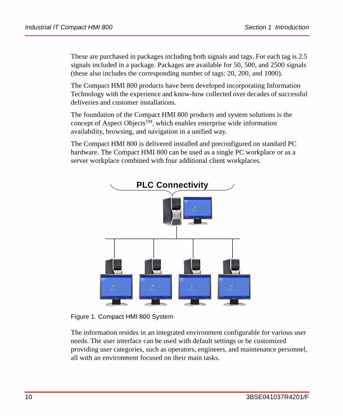
The Compact HMI 800 is delivered installed and preconfigured on standard PC hardware. The Compact HMI 800 can be used as a single PC workplace or as a server workplace combined with four additional client workplaces.
The information resides in an integrated environment configurable for various user needs. The user interface can be used with default settings or be customized providing user categories, such as operators, engineers, and maintenance personnel, all with an environment focused on their main tasks.
Figure 1. Compact HMI 800 System
PLC Connectivity
10 3BSE041037R4201/F

Section 1 Introduction Purpose, Scope and Intended Use
ProductGuideSV4.book Page 11 Tuesday, May 20, 2008 1:47 PM
As a result, the user can concentrate on the right actions, with a minimum of effort, resulting in increased productivity.
Within the Compact HMI 800 there are a number of Core Functional Areas. These are:
• Core System
• Operations
• Engineering
These Core Functional Areas are described in section 3.
Compact HMI 800 can be used together with AC 800M or with any other PLC.The controllers are accessed using the OPC standard interface.
Purpose, Scope and Intended Use
The scope of the Compact HMI 800 described in this document is:
• Traditional process automation, as well as hybrid automation. The control level ranges from simple binary control to closed loop control.
Aspect Objects ArchitectureThe Aspect Objects architecture is a cornerstone of the Compact HMI 800 concept. It provides:
• A consistent, scalable concept that integrates Process Control & Automation products.
• Information-centric navigation – a consistent way to instantly access all information without having to know how and by which application the information is handled.
• Integration of autonomous applications. Very little awareness is required between applications.
• Easy integration of new aspect systems (new applications). A homogeneous base for all applications. Open standards make it possible for users to integrate new aspect systems.
3BSE041037R4201/F 11

Aspect Objects Architecture Section 1 Introduction
ProductGuideSV4.book Page 12 Tuesday, May 20, 2008 1:47 PM
• High level of engineering efficiency through data integration between aspect systems.
• Extensive re-use during the life cycle. For example copy/paste, definition of object types and solutions, etc.
A central problem in plant operations, as well as asset life cycle management, is the need to organize, manage, and have access to information for all different aspects of a great number of plant and process entities. These entities, or real world objects, are of many different kinds. They can be physical process objects, like a valve, or more complex, like a reactor. Other examples are: products, material, batch procedures, manufacturing orders, and customer accounts.
Aspect
Each of these real world objects can be described from several different perspectives. Each perspective defines a piece of information and a set of functions to create, access, and manipulate this information. We call this an aspect of the object.
Figure 2. Examples of Different Aspects of an Object
Quality report
Cost of operation
Production report
Operator Graphics
Control
Simulation
Functional Description
M
12 3BSE041037R4201/F

Section 1 Introduction Terminology
ProductGuideSV4.book Page 13 Tuesday, May 20, 2008 1:47 PM
Aspect System
A software system that implements one or several aspect types by providing one or several aspect system objects.
It is necessary to be able to implement these aspects using many different applications, both existing and new, from ABB, third parties and customers, both now and in the future. It is desirable to be able to do this without changes to the applications. It is not reasonable to require that all these different applications be aware of each other. Still, the applications must cooperate to provide an integrated view and functionality of the object.
Aspect Objects
Aspect Objects provide a solution to this problem. In this concept, rather than creating one single object or data model in the system to represent the real world object, each aspect is modeled separately. An Aspect Object is thus not an object in a strict sense, e.g. like a COM object, but rather a container of references to implementations of the different aspects.
TerminologyThis list contains descriptions for terms and abbreviations that are used in this document.
Table 1. Terms and Definitions
Term Description
ActiveX Microsoft standard for user interface components, based on definition of software interfaces.
AS Aspect Server. The “central” intelligence in the system, including the aspect directory and other services related to object management, names, security, etc.
Aspect See Aspect on page 12
Aspect Objects See Aspect Objects on page 13
Aspect System See Aspect System on page 13
3BSE041037R4201/F 13

Terminology Section 1 Introduction
ProductGuideSV4.book Page 14 Tuesday, May 20, 2008 1:47 PM
CEXbus Communication module expansion bus used in the AC 800M Controller.
CNCP Control Network Clock Synchronization Protocol
COM (Microsoft) Common Object Model.
CS Connectivity Servers provide access to controllers and other data sources.
CTK Configuration Tool Kit
DCS Distributed Control System. A generic term for control systems for Process Automation, normally with a distributed database and real time data access.
DCU Distributed Control Unit
DMZ Demilitarized Zone
DTM The Device Type Manager - DTM - is a software module delivered by the manufacturer together with a device. As an “FDT device driver” the DTM contains all device-specific data, functions, and graphical user interfaces and provides uniform access to these device-specific internals via the standardized FDT interfaces.
ECCP Ethernet Communications Controller for the PCI bus
EPA Environmental Protection Agency
ERP Enterprise Resource Planning.
ES Engineering System, which is used for engineering and potential test of applications intended for Production System
FDA Food and Drug Administration
FDT Field Device Tool. It is an open standardized communication interface for integrating field devices and their application into control systems or device management tools, e.g. Engineering Tools and Asset Management Tools.
Table 1. Terms and Definitions (Continued)
Term Description
14 3BSE041037R4201/F

Section 1 Introduction Terminology
ProductGuideSV4.book Page 15 Tuesday, May 20, 2008 1:47 PM
FF FOUNDATION Fieldbus.
GSM Global System for Mobile communication
HSE High Speed Ethernet (FOUNDATION Fieldbus)
HSI Human System Interface
HMI Human Machine Interface
IndustrialIT IndustrialIT is ABB’s solution that creates a business enterprise where your plant automation, Asset Optimization, and collaborative business systems are seamlessly linked in real time.
MES Manufacturing Execution System
NIC Network Interface Card
NLS National Language Support
Node A computer communicating on a network, e.g. the Internet, Plant, Control or I/O network. Each node typically has a unique node address with a format depending on the network to which it is connected.
ODBC Open Data Base Connectivity
OCS Open Control System. Similar meaning as DCS
OLE Object Linking and Embedding
OPC OLE for Process Control, a standard interface for data, event and history access based on COM.
PA Process Automation
Plant Explorer An application that is used to create, delete and organize Aspect Objects and Aspects in the Compact HMI 800. The plant explorer organizes the Aspect Objects in structures according to functionality, location, etc.You can also use it to browse and search the structures of the plant.
Table 1. Terms and Definitions (Continued)
Term Description
3BSE041037R4201/F 15

Applicable Standards and Specifications Section 1 Introduction
ProductGuideSV4.book Page 16 Tuesday, May 20, 2008 1:47 PM
Applicable Standards and Specifications
Openness provides solutions that enable and protect the future growth of the system. To utilize this openness, Compact HMI 800 conforms to standard technologies like OPC, Microsoft COM, ActiveX, IEC 61131-3.
The following table list the major standards incorporated into or supported by Compact HMI 800.
PLC Programmable Logic Controller. Controller for primarily discrete logic control.
PNSM PC, Network and Software Monitoring
PS Production System which is used for controlling a real process
RNRP Redundant Network Routing Protocol
SIL Safety Integrity Level
SIS Safety Instrumented System
SMS Short Messaging Service
SNMP Simple Network Management Protocol
SNTP Simple Network Time Protocol
SOE Sequence of Events
SQL Standard Query Language
UTC Coordinated Universal Time
VPN Virtual Private Network
WMI Windows Management Instrumentation
Table 1. Terms and Definitions (Continued)
Term Description
16 3BSE041037R4201/F

Section 1 Introduction Applicable Standards and Specifications
ProductGuideSV4.book Page 17 Tuesday, May 20, 2008 1:47 PM
Table 2. Standards
Standard Description
ActiveX Microsoft standard User Interface
COM Microsoft standard
DIN EN 500 22 Standard for DIN rail used by Module Termination Unit
EMC Directive 89/339/EEC
CE Compliance Directives (standards; EN 61131-2, EN 50081-2, and EN 50082-2)
FDT/DTM Concept for fieldbuses
IEC 61131-3 IEC Standard for programmable controllers
IEC 61508 IEC Standard for SIL1-2
IEC 61512 (ISA S88) IEC Standard for Batch Management
IEEE 802.3 Ethernet
ISO-9506 Standard for sending information between industrial applications.
Low Voltage Directive 73/23/EEC
CE Compliance Directive (standards; EN 50178, EN 60950, EN 61010, EN 50178, EN 60439, or IEC 60255, depending on product)
OLE DB COM based application programming interface (API) for data access
OPC OLE for Process Control. Standard for standard data, event, and history access based on COM
S95 The ISA S95 Standard for Enterprise-Control System Integration defines interfaces between applications at the Industrial Control Level and applications at the MES (Manufacturing Execution Systems) Level
TCP/IP Defacto standard for computer networking
3BSE041037R4201/F 17

Related Product Guides and Release Notes Section 1 Introduction
ProductGuideSV4.book Page 18 Tuesday, May 20, 2008 1:47 PM
Related Product Guides and Release NotesThe list below specifies the available Appendices and Product Guides describing related products and Controller Connectivity.
For references to concerned price lists, see Price List Structure on page 90.
Table 3. Appendices for related products and controller connectivity
Title Document Identity
PLC Connect 3BSE038018R4101 Appendix E
Compact Control Builder SV 4.1 Product Guide 3BSE039837R201
18 3BSE041037R4201/F

ProductGuideSV4.book Page 19 Tuesday, May 20, 2008 1:47 PM
Section 2 Key Benefits
Industrial IT Compact HMI 800 extends the reach of the traditional automation systems beyond control of the process to achieve the productivity gains necessary to succeed in today's business markets. For the first time, this scope is accessible from a single user interface that is configured to present information and provide interaction in a context appropriate to all user disciplines.
Compact HMI 800's unique operating environment allows the incorporation of "best in class" products, applications and services from the world's largest automation supplier. Built on the Industrial IT Aspect ObjectTM technology platform and industry specific expertise, ABB's automation portfolio provides the seamless link between process and business management to deliver knowledge-based solutions.
Features and Benefits
• Full functionality: Including dynamic graphics, event and alarm handling, graphic trending, historical data storage, reporting, faceplates, etc., etc.
• Open to any controllers: Supports the OPC standard, meaning that it is directly interfaceable to the large and growing number of OPC-compliant controllers. Drivers are also available for the most popular, non-OPC-compliant PLCs.
• Pre-installed: Delivered as a complete system with factory installed software.
• Easy to Engineer: Delivered preconfigured and ready for plant- and process specific adaptation.
• Easy to Operate: Intuitive point-and-click-style operation, to the Windows standard, from overview to detail and back.
• Easy to Maintain: Comes with built-in, automatic, back-up functionality.
3BSE041037R4201/F 19

Reducing Time to Decision and Action Section 2 Key Benefits
ProductGuideSV4.book Page 20 Tuesday, May 20, 2008 1:47 PM
Enhancing Reliability. Embracing the principles of open, real-time networking, Compact HMI 800 provides a scalable solution that spans and integrates loop, unit, area, plant, and interplant controls. From providing a secure foundation with robust, but flexible, base level regulatory and sequence control to higher level management and advanced control functions, Compact HMI 800s meet the application needs of a wide variety of industries.
Compact HMI 800 provides a secure, reliable, control environment through built in security features such as access control, user authentication, and audit trail capability. ABB enhances secure system operations by incorporating "safe design" practices into product development, and by providing Compact HMI 800 hardening settings.
Based upon the Aspect Object technology and a common set of hardware, Compact HMI 800 seamlessly integrates traditionally isolated control systems.
Compact HMI 800 delivers its extended productivity gains by:
• Reducing Time to Decision and Action
• Engineering for Maximum Performance
These key value propositions are described in the paragraphs below.
Reducing Time to Decision and Action
Compact HMI 800 delivers the exact information - filtering out the noise - to facilitate consistent, sound business decisions and provides the environment to optimize the associated response.
Compact HMI 800 Operator Workplace, each user's login defines the type and class of information required for timely and informed decision-making. Thus, Compact HMI 800 delivers much more than a comprehensive operator console; Compact HMI 800's personalized workplaces provide an intelligent and focused presentation, enabling rapid response.
Optimal reaction requires real-time knowledge that an upset has occurred, or will occur. Compact HMI 800 provides notification through its audible and visual alarm and event presentation. Remote personnel are notified of critical events via mobile telephones, e-mail accounts, and pagers by Compact HMI 800's SMS and e-mail messaging service. Using GSM mobile phone technology, Compact HMI 800 allows remote acknowledgement of notification and confirmation of receipt.
20 3BSE041037R4201/F

Section 2 Key Benefits Engineering for Maximum Performance
ProductGuideSV4.book Page 21 Tuesday, May 20, 2008 1:47 PM
Compact HMI 800 features include:
• Personalized workplaces for focused information access: Workplace layouts are adjusted and optimized to user preferences and needs with individualized menus, toolbar contents, and display locations. At delivery a layout adapted for Compact HMI 800 is configured.
• Intuitive and flexible navigation for fast information access: Quick access with familiar web browser tools to displays and information is provided. Favorites, history lists, shortcuts, and hot buttons provide navigation through a process production facility quickly and accurately.
• Comprehensive operator functionality for reliable control: Compact HMI 800 Operator Workplace provides a complete set of operator functions that include realistic process graphics with standard faceplates, superior trending capabilities, intelligent alarm and event handling, production reporting, and remote messaging.
Engineering for Maximum Performance
Providing a single, accurate, source of system information helps ensure data consistency and improves engineering performance throughout the lifetime of the automation system.
Compact HMI 800 Engineering provides real-time information integration for better and faster access. Working within a common engineering environment, Compact HMI 800 Engineering supports a consistent information flow from design, through installation and commissioning, to operation and maintenance.
Compact HMI 800Compact HMI 800 helps users engineer for maximum performance with:
• A fully integrated engineering environment for development and reuse of system standards, such as incorporating control logic, operator displays, maintenance support, and documentation.
• A single source for all data within the system.
• A comprehensive set of libraries to streamline the engineering workflow.
Compact HMI 800 Engineering features include:
3BSE041037R4201/F 21

Integration of Installed Systems Section 2 Key Benefits
ProductGuideSV4.book Page 22 Tuesday, May 20, 2008 1:47 PM
• Reusable Solutions. The common framework allows logically defined solutions to be quickly reproduced and adapted to meet specific needs with minimum engineering and re-validation. When modifications are made to existing standards, instances are automatically updated. This is only valid for aspects inherited from object types, and for added new aspects.
• Operator Graphics. Interactive operator graphics can easily be customized through the use of predefined elements and symbols.
• Change Management. System configuration changes can be recorded and tracked to help meet regulatory requirements.
• Integrated Documentation. Documentation of all integrated components and devices are easily accessible.
Integration of Installed Systems
The Compact HMI 800 can also be used to enhance existing installations. Enhancement is based on a number of assumptions, which determine the connectivity and evolution capabilities.
Different levels of an automation system may have different lifetime cycles. The workplace and server level typically has the fastest development. The customer’s readiness to upgrade is also higher on workplace and server level than on controller and I/O levels. From this the following conclusions are made:
• New workplace and server products connect to existing PLC’s.
• New PLC’s connect to existing process I/O.
• A user´s investment in their application often has a larger value than the hardware and software investment. Hence, application conversion tools are provided to bring applications over from the existing to the new product.
22 3BSE041037R4201/F

ProductGuideSV4.book Page 23 Tuesday, May 20, 2008 1:47 PM
Section 3 Compact HMI 800
Compact HMI 800 OverviewThe Compact HMI 800 functionality is divided into a core system and a set of function modules. The modules represent functions that are needed for the process that shall be controlled. The modules are grouped in a set of Functional Areas for an easier overview of the complete product functionality.
The Compact HMI 800 software structure is summarized as follows:
• Core System is the system base software. It consists of
– Core System Functionality.
– Integration of almost any controller via PLC Connect.
– Real Time Data Client Connection, Audit Trail, Advanced Access Control, SMS and e-mail Messaging, etc.
Figure 3. Compact HMI 800 Functional Areas
3BSE041037R4201/F 23

Core System Section 3 Compact HMI 800
ProductGuideSV4.book Page 24 Tuesday, May 20, 2008 1:47 PM
• In addition to the Core System the following Core Functional Areas are defined:
– Operations.
– Engineering.
Core SystemThe Compact HMI 800 base functionality is comprised of the Core System consisting of:
• Plant Explorer for creating and maintaining Aspect Objects and object structures.
• Alarm and Event handling for detection, generation, and logging of alarms and events.
• Security for handling of user permissions and authority in the control system.
• System Time Synchronization to synchronize the system time in the different nodes (PCs and controllers).
• Backup and Restore, handling back up and restore of the Compact HMI 800.
• Export and Import of application data
• Localization. The Compact HMI 800 is available in US-English. The Core System has support for making the localization to other languages.
Plant Explorer
The Plant Explorer is used to create, delete, and organize Aspect Objects and Aspects within the Compact HMI 800. It organizes the Aspect Objects in structures according to functionality, location, etc. You can also use it to browse and search the structures of the plant.
Plant Explorer is the main tool used by engineers for exploring and building hierarchically structured models of a plant or system. It is based on a structural hierarchy, similar to Windows Explorer. The structures represent different views of the plant. Structures can be built and improved at any time. Examples of different types of structures are:
24 3BSE041037R4201/F
Section 3 Compact HMI 800 Plant Explorer
ProductGuideSV4.book Page 25 Tuesday, May 20, 2008 1:47 PM
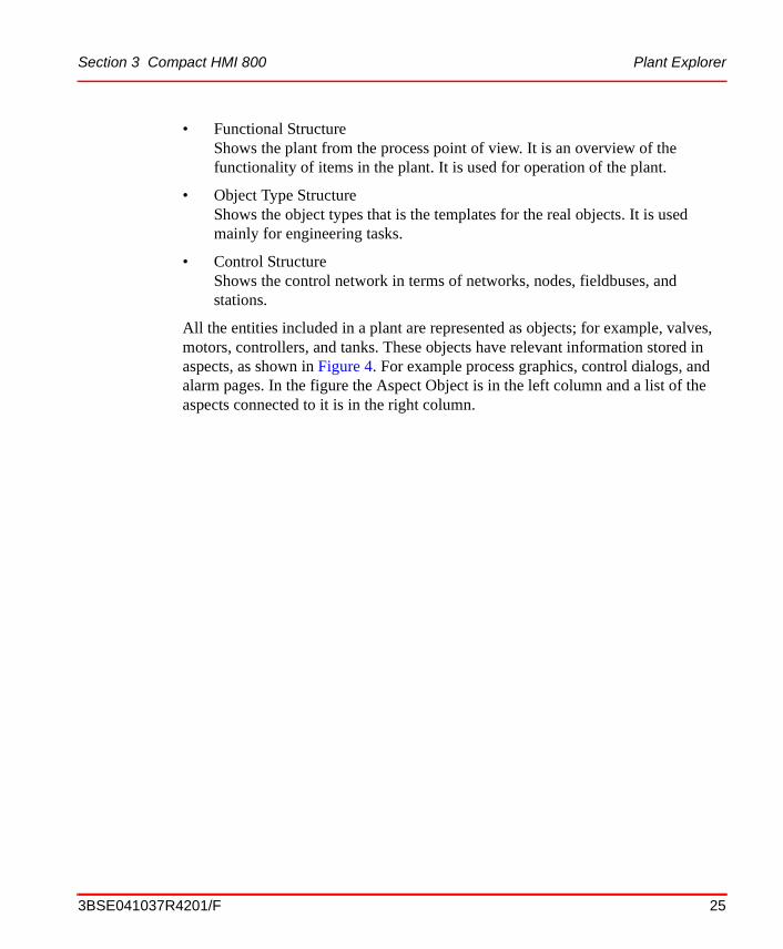
• Functional StructureShows the plant from the process point of view. It is an overview of the functionality of items in the plant. It is used for operation of the plant.
• Object Type StructureShows the object types that is the templates for the real objects. It is used mainly for engineering tasks.
• Control StructureShows the control network in terms of networks, nodes, fieldbuses, and stations.
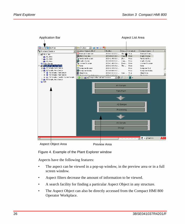
All the entities included in a plant are represented as objects; for example, valves, motors, controllers, and tanks. These objects have relevant information stored in aspects, as shown in Figure 4. For example process graphics, control dialogs, and alarm pages. In the figure the Aspect Object is in the left column and a list of the aspects connected to it is in the right column.
3BSE041037R4201/F 25
Plant Explorer Section 3 Compact HMI 800
ProductGuideSV4.book Page 26 Tuesday, May 20, 2008 1:47 PM
Aspects have the following features:
• The aspect can be viewed in a pop-up window, in the preview area or in a full screen window.
• Aspect filters decrease the amount of information to be viewed.
• A search facility for finding a particular Aspect Object in any structure.
• The Aspect Object can also be directly accessed from the Compact HMI 800 Operator Workplace.
Figure 4. Example of the Plant Explorer window
Preview AreaAspect Object Area
Application Bar Aspect List Area
26 3BSE041037R4201/F

Section 3 Compact HMI 800 Alarm and Event
ProductGuideSV4.book Page 27 Tuesday, May 20, 2008 1:47 PM
Alarm and Event
There is support for alarm & event management on several levels throughout the system. Alarms and events are treated in a consistent way (an alarm is an event that alerts the user of an abnormal state and needs to be acknowledged). The core system supports management and logging of events.
Supported levels of alarm & event management can be described as:
• Event detection provided on controller, field, and application level
• The core system supports storing and state management of events and alarms.
– The Alarm Manager sets up subscription for alarms and events from event collectors in the Connectivity Servers. Events are sent to the System Message Server for retrieval purposes.
– Redundancy is applied to the Alarm Manager, via several alarm servers that work in parallel, receiving the same alarms. One master exists which re-distributes alarms to the client. If the master goes down, another server becomes master. A synchronization of data with the current master takes place when a redundant Alarm server starts up after a failure.
• On the application level, Operator Workplace and history functions provide the presentation of alarms and events.
– Alarm logger for printer output.
– Alarm bands to provide a number of active and unacknowledged alarms in a summary display for selected alarm lists.
– The Sequence bar displays a defined number of alarms horizontally.The alarms shown are the newest alarms from the defined list.
– SMS and e-mail Messaging provides a method for sending messages based on alarm and event information to user devices such as mobile telephones, e-mail accounts, and pagers.
– All client applications are applying filters which are configured as part of the alarm or event list to determine which alarms or events from the system global alarm or event stream shall be included in the client functions.
– Alarm list configurations can be shared between lists.
3BSE041037R4201/F 27

Alarm and Event Section 3 Compact HMI 800
ProductGuideSV4.book Page 28 Tuesday, May 20, 2008 1:47 PM
– If an alarm is irrelevant it should not be shown in an alarm list. An alarm is irrelevant if it doesn’t require an action from the operator. A function called hiding will help the operator to clear the alarm lists from irrelevant alarms.
The functionality provided by the Operator Workplace is described in the Operations Section.
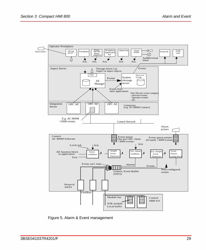
The following picture, Figure 5 show the overall flow of alarms and events, starting in the AC 800M controller. Buffering of events takes place at several levels in the system. Such buffers, or queues, are shown. Presentation and acknowledgement can be made in several ways as discussed above.
28 3BSE041037R4201/F
Section 3 Compact HMI 800 Alarm and Event
ProductGuideSV4.book Page 29 Tuesday, May 20, 2008 1:47 PM
Figure 5. Alarm & Event management
ControlS800 I/O
SOE moduleLocal buffer
Module bus
Protocolstacks
Fieldbus
Generic Event Buffer(FIFO)
Text
AE function blockin application
Local ack. Ack. Ack
Alarmcondition
Simple
Event
Detection
Ext. Alarm
conditionExt. Simple
Event Detection
Event
Printer
config block
Non-configured events
EventsAlarmsEvent, incl. time
Alarmprinter
Event queue printer(if used) <3000 events
Event queueOne per OPC client<3000 events-
Control AC 800M Software
OPC AE OPC AE OPC AE
AE
Short term
System
AE log FaceplatesAlarm Workplace Alarm list Alarm
serverbar/line Alarm sequence
Applicationbar
action
Manager
Filter
message server
Events
Events from other applications
Alarm printer
Ack. Ack. Ack. Ack. Ack.
Connectors(e.g. AC 800M Connect)
E.g. AC 800M<5000 events
Through Alarm ListAspect of aspect objects
One file per event category- process events- operator events- etc.
storage
Operator Workplace
Aspect Server
Control Network
Audible/visual alarm
Events
Event list Audittrail
IntegrationServer
3BSE041037R4201/F 29

Trend Logs Section 3 Compact HMI 800
ProductGuideSV4.book Page 30 Tuesday, May 20, 2008 1:47 PM
Trend Logs
The ability to store, view, and retrieve process data and historical information is an integral function of the automation system. To accomplish this, the system provides scalable options to satisfy the information needs of all levels of users, including process operators, engineers, maintenance personnel, and operations managers.
The history system functionality is divided into Core System History functions, and Operator Workplace.
The history functions in the Core System are:
• Event storage (up to 50,000 events)
• Trend data storage (up to 2,000 logs)
Security
Operations/actions in the system can be assigned different required permissions. This assignment defines what permission a user needs to have in order to perform the operation/action. Examples of permissions are: Read, Configure and Operate. To execute a setpoint change, for example, Operate permission may be required. Each attribute of a control object can have a different permission assigned, so that access rights can be differentiated down to a particular operation to an object.
The foundation for Compact HMI 800 user administration is the Windows user administration. A user is registered in Windows, and can belong to one or more groups. The user group can be freely selected, but it may simplify user administration if the user groups correspond to the Industrial IT user groups.
Roles will control what is visible to a certain user group (here Industrial IT user groups apply). For example, Controller limits in the faceplate can be made invisible for an operator.
In the finest granularity, the above-mentioned functionality gives the administrator the possibility to define exactly who can do what and from where. The functionality can be applied to each aspect in the system at the same time in order to provide basic security with minimum setup.
The user groups are assigned different permissions relative to substructures down to an individual object. This supports the concept of users/ user groups having different authority for different areas of the system. Authority is set at an Aspect
30 3BSE041037R4201/F
Section 3 Compact HMI 800 Clock synchronization of Workplaces
ProductGuideSV4.book Page 31 Tuesday, May 20, 2008 1:47 PM
Object in an arbitrarily selected structure, such as the functional structure. All sub-ordinate objects inherit this authority. It is also possible to set authority explicitly for any single Aspect Object.
Default configurations of security are available to reduce the system configuration work.
User log-over
User log-over provides the ability to temporarily change users without a complete Windows logon/logoff sequence. This makes it much faster, for example, for another user to log in to perform tasks which require a higher authority level without logging off the current user. The information displays remain available.
Clock synchronization of Workplaces
System-wide time synchronization of all nodes handling time related data is supported. The AfwTime Service is used to synchronize the time on the server and client nodes defined in a system. This service can also be used to change the current time in the system.
The Time Service has two components, a Time Server and a Time Client.
• Time Server.
The Time Server component is the administrator of the clock synchronization. It receives and distributes the clock synchronization telegrams to/from other nodes, and it makes the final decision on which telegram to accept and broadcast to the network. The clock synchronization telegram comes from the Clock Master (normally an AC 800M controller).
The Time Server is normally active in the Connectivity Servers.
• Time Client
A Time Client is responsible for keeping the date and time in its node updated and synchronized with the global time broadcast from the Time Server. It is also responsible for allowing or disallowing manual setting of date and time, according to how it is configured. A Time Client resides in all Compact HMI 800 nodes.
3BSE041037R4201/F 31

Clock synchronization of Workplaces Section 3 Compact HMI 800
ProductGuideSV4.book Page 32 Tuesday, May 20, 2008 1:47 PM
Daylight Savings Time is supported and handled as a presentation issue. The system time, the event detection, and the storage of events are done in universal time (UTC) in order to keep track of the correct sequences and across any time changes.
Windows Backup and Restore
Before backing up the system application data, the Windows system must be fully backed up. This can be performed with the included Symantec GhostTM software or or Windows backup. The backup should include the system and all used system extensions.
In case of a disk crash you use the full Windows backup and the Windows Backup tool to restore the system to the same state as it was before the disk crash.
Compact HMI 800 Backup and Restore
The backup stores all Aspect Objects and aspect data to a disk at a configurable location. It also stores service data that is not stored in the Aspect Directory.
Backups are either full or incremental. The server workplace includes a second Hard Disk and a DVD writer to support the handling of the back-up data.
Backups are always made on a running system. They can be started manually or scheduled.
The Backup Restore function makes it possible to make an on-line backup of a node and perform an off-line restore to any node.
The Maintenance Structure contains the backup definitions as well as backups which have been executed.
The restore recreates a system equivalent to the original after a computer failure. It is also a recommended way to transfer data between one version of the system to another during an upgrade.
The Backup function is also used to create a complete System Configuration Version with an identity.
32 3BSE041037R4201/F

Section 3 Compact HMI 800 Export and Import of Application Data
ProductGuideSV4.book Page 33 Tuesday, May 20, 2008 1:47 PM
Export and Import of Application Data
The Import/Export tool is an instrument for storage and distribution of objects and aspects. An object and aspect structure can be saved and then imported into the same or another part of the structure. Data from the system, in the form of objects and aspects, can be imported and exported into archive files.
The system enforces that exported data contain all necessary data to fully restore the functionality of the exported objects. Data that the object function is dependent on will automatically be included, even if they belong to other objects or even other structures.
PLC Connect
PLC Connect provides an integration of PLC-controllers into the Compact HMI 800. This function makes it possible to access PLC based control functionality in a similar fashion to other integrated PLCs.
PLC Connect acts as an integrated controller integration towards Industrial IT Compact HMI 800. As a result, integration into the Industrial IT concept is achieved. PLC Connect thus makes it possible to configure the Compact HMI 800 as a hybrid PLC system.
ABB controllers that do not have a dedicated integration option available, are integrated into the Industrial IT Compact HMI 800 by means of PLC Connect.
PLC Connect adds traditional PLC type functionality as an integrated part of the Industrial IT concept. This means that traditional system capabilities, typically requiring a large number of process I/O:s to be connected through a range of controllers from different manufacturers, can be realized with an Industrial IT Compact HMI 800.
PLC Connect provides the following features:
• Basic object types for PLC type signals and softpoint signals.
• Configuration tools for creating and editing PLC type objects.
• A full set of faceplates for the PLC type objects.
• Integrated Real Time Database (RTDB) to keep an updated image of connected process points as well as calculated softpoints.
3BSE041037R4201/F 33

System Options Section 3 Compact HMI 800
ProductGuideSV4.book Page 34 Tuesday, May 20, 2008 1:47 PM
• Communication drivers.
• Dial Manager for remote communication.
• Alarms detection and OPC Alarms and Events generation for PLC binary signals.
• Alarm limit detection and OPC Alarms and Events generation for PLC integer and real signals.
• Open interface to PLC signals and softpoints from application programs in VB and C++.
PLC Connect is typically used in the following cases:
• For integration of AC800M/C Industrial IT Baseline 2 controllers when full DCS controller integration is not required.
• When remote connection of PLCs and RTUs are required.
System Options
FDA 21 CFR Part 11 Support
The US Food and Drug Administration (FDA) issued 21 CFR Part 11 in response to the pharmaceutical industry’s request to utilize paperless record systems under the current good manufacturing practice (cGMP) regulations in parts 210 and 211 (21 CFR parts 210 and 211). Part 11 went into effect on August 20, 1997. The regulation does not require a manufacturer to maintain records electronically. However it does provide the criteria under which the FDA will consider electronic records to be equivalent to paper records.
The support of compliance to 21 CFR Part 11 is an absolute, non-negotiable requirement for automation products sold into manufacturing environments subject to FDA regulation. This is primarily a concern for manufacturers in the life science industry, but can also include food, beverage, and cosmetics manufacturers as well. Also some chemical and other manufactures who supply materials to the life science industry are required to comply with the regulation.
34 3BSE041037R4201/F

Section 3 Compact HMI 800 FDA 21 CFR Part 11 Support
ProductGuideSV4.book Page 35 Tuesday, May 20, 2008 1:47 PM
The requirements for Compact HMI 800 to enable compliance have been categorized in the following table. Several requirements identified in 21 CFR Part 11 require the system owner to comply by having appropriate Standard Operating Procedures (SOPs) in place. Not all of the required SOPs are included with Compact HMI 800 product offering, however ABB engineering services for validation can provide assistance in creating the appropriate documentation on a project basis. The primary sections from Part 11 are listed below.
Subpart B – Electronic Records
Sec 11.10 – Controls for closed systems
Sec 11.30 – Controls for open systems
Sec 11.50 – Signature manifestations
Sec 11.70 – Signature/record linking
Subpart C – Electronic Signatures
Sec 11.100 – General requirements
Sec 11.200 – Electronic signature components and controls
Sec 11.300 – Controls for identification codes/passwords
Table 4. Feature Categories
Feature Category Section references from 21 CFR Part 11 Regulation
Authorization SubPart B, Sec 11.10: (g)
Access Control SubPart B, Sec 11.10: (d)
Electronic Signature SubPart B, Sec 11.50: (a)
Subpart B, Sec 11.70
Subpart C, Sec 11.100: (a)
Subpart C, Sec 11.200: (a),(1), (i), (ii), (3)
Subpart C, Sec 11.300: (a), (b), (d)
3BSE041037R4201/F 35
Authorization - User Re-authentication and Double Authentication Section 3 Compact HMI 800
ProductGuideSV4.book Page 36 Tuesday, May 20, 2008 1:47 PM
Authorization - User Re-authentication and Double Authentication1
Re-authentication can be optionally used for critical operations such as writes to the control system, batch operations, and configuration changes in order to ensure that only authorized persons can take actions in the Compact HMI 800. This option forces the user to re-supply his/her user credentials before the operation is executed. A double authentication may also be optionally used. In this case an additional person who has the respective secondary authentication authority has to give username and password in order to approve the operation.
Access Control
Access to the Compact HMI 800 is controlled by the core system's security function. See Security on page 30.
Electronic Signature - Digital Signature
Electronic signatures are supported as a Digital signature for all aspects of objects. A digital signature is generated and linked to an aspect. User verification via electronic method is performed by using Windows user id and password in combination with a selected reason for signature and an optional comment.
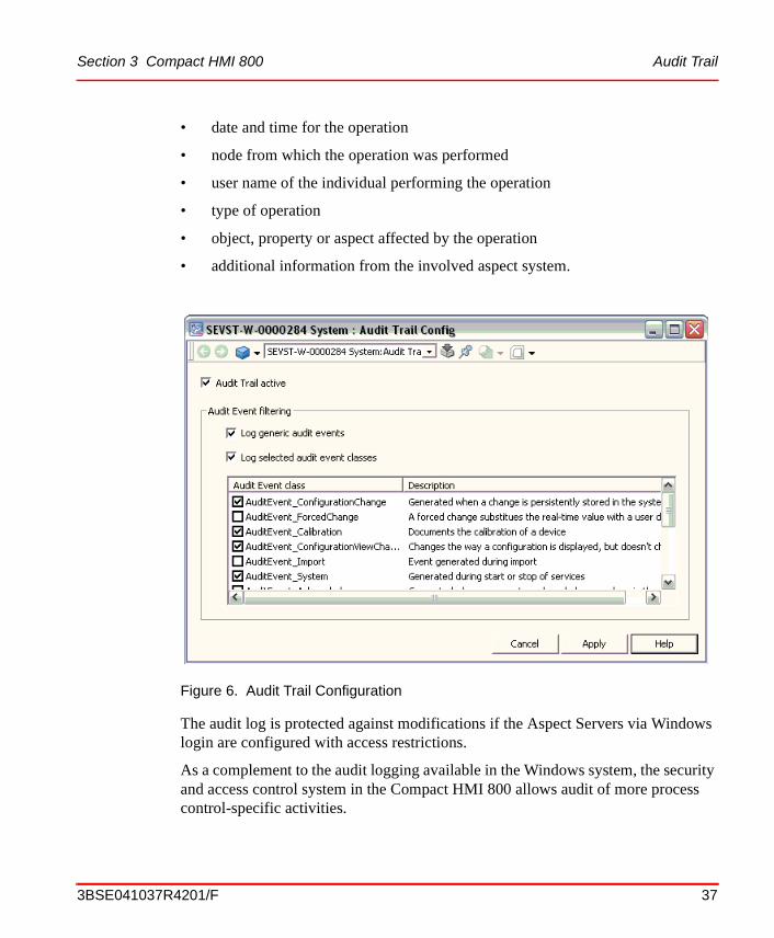
Audit Trail
The Security and Access Control System allows audit of operator actions and security. The system supports logging of security violations, configuration changes, and operator actions to the process.
The audit logs can be viewed in the alarm and event list. This makes it possible to see the effect of an operation. The audit log contains the following information:
Audit Trail SubPart B, Sec 11.10: (a), (e)
SubPart B, Sec 11.50: (a), (b)
System Checks SubPart B, Sec 11.10: (f), (h)
1. User re-authentication and double authentication are together with user log-over called Advanced Access Control in price lists, etc. See User log-over on page 31
Table 4. Feature Categories (Continued)
36 3BSE041037R4201/F
Section 3 Compact HMI 800 Audit Trail
ProductGuideSV4.book Page 37 Tuesday, May 20, 2008 1:47 PM
• date and time for the operation
• node from which the operation was performed
• user name of the individual performing the operation
• type of operation
• object, property or aspect affected by the operation
• additional information from the involved aspect system.
The audit log is protected against modifications if the Aspect Servers via Windows login are configured with access restrictions.
As a complement to the audit logging available in the Windows system, the security and access control system in the Compact HMI 800 allows audit of more process control-specific activities.
Figure 6. Audit Trail Configuration
3BSE041037R4201/F 37

SMS and e-mail Messaging Section 3 Compact HMI 800
ProductGuideSV4.book Page 38 Tuesday, May 20, 2008 1:47 PM
The audit event list is user configurable to either show more information, or to filter out specific events from the complete event list.
The audit list is stored on disc. The size of the storage is configurable.
SMS and e-mail Messaging
SMS and e-mail Messaging provides a method for sending messages based on alarm and event information to user devices such as mobile telephones, e-mail accounts, and pagers. It is possible to control sending messages by configuring a message schedule for each user. The message schedule allows one active paging time interval for each day of the week.
Figure 8 shows and Table 5 lists the three methods SMS and e-mail Messaging employs to notify users of alarm and event information. The table also lists the devices that are compatible with each notification method, and which devices, using the SMS/GSM notification method, allow the user to confirm receipt of the message back to the Compact HMI 800.
Figure 7. An Example of an Audit List
38 3BSE041037R4201/F

Section 3 Compact HMI 800 SMS and e-mail Messaging
ProductGuideSV4.book Page 39 Tuesday, May 20, 2008 1:47 PM
Figure 8. SMS and e-mail Messaging Notification Methods
Table 5. Notification Methods
Device(1)Notification Method
SMTP/E-mail
TAP/Modem
SMS/GSM
Numeric Pager — — —
Alphanumeric Pager Notify Notify Notify
2-Way Pager - Fixed Reply Notify Notify Notify
2-Way Pager - User Entered Reply Notify Notify Notify/Confirm Receipt
2-Way GSM Pager Notify Notify Notify/Confirm Receipt
Text Messaging Enabled Telephone Notify Notify Notify/Confirm Receipt
Wireless Equipped PDA Notify Notify Notify/Confirm Receipt
E-mail Notify Notify/Confirm Receipt
(1) This table lists the capabilities of SMS and e-mail Messaging. The selected hardware and/or service provider may impose other limiting factors.
Service Provider(Short Message Service Center,
SMTP Server,Central Paging Terminal)
SMTP/E-MAIL
SMS/GSM TAP/MODEM
Target Device(Mobile PhoneE-mail, Pager)
Internet
Wireless Land Tele-phone Line
3BSE041037R4201/F 39
Calculation Engine Section 3 Compact HMI 800
ProductGuideSV4.book Page 40 Tuesday, May 20, 2008 1:47 PM
The notification methods work as follows:
• SMS (Short Message Service)/GSM (Global System for Mobile Communication) - is used to send messages based on alarm and event information to the GSM service provider's SMS Center (SMSC) over a wireless network. The SMSC sends the message to compatible devices of users configured to receive them. This method allows users of the compatible devices to confirm receipt of the message.
• SMTP (Simple Mail Transfer Protocol)/E-mail - is used to send messages based on alarm and event information to an SMTP server over the Internet. The SMTP server sends the message to e-mail accounts, or to compatible devices via e-mail accounts, of users configured to receive them.
• TAP (Telocator Alphanumeric Protocol)/Modem - is used to send messages based on alarm and event information to the pager service provider's CPT (Central Paging Terminal) over a land telephone line. The CPT sends the message to compatible devices of users configured to receive them.
Calculation Engine
Calculations can be performed on any object or value in the system and are supported by Windows 2000 Visual Basic scripting language. The calculation services application is an Aspect System and is included as an option to the base. The Calculations Services provide the ability to run mathematical calculations on any available Compact HMI 800 aspect property or attribute. This includes a special set of aspect objects called Softpoints, see SoftPoint Server on page 41. Calculations may also be applied to system object types. This allows configuration re-use of calculations. Calculation operations can be triggered by changes to system point values, or can be scheduled to execute either cyclically or at a given date and time. A calculation aspect may be applied to any Aspect Object such as a unit, vessel, pump, or softpoint. Inputs can be any Aspect Object property, and outputs can be any changeable point in the system. Data quality and alarm generation are supported. Calculation logic is written in VBScript.
40 3BSE041037R4201/F

Section 3 Compact HMI 800 Calculation Engine
ProductGuideSV4.book Page 41 Tuesday, May 20, 2008 1:47 PM
SoftPoint Server
SoftPoint services allow you to create and configure user defined object types, and deploy them like any other object in the base system. A softpoint is different from other system points because it is not directly connected to hardware system I/O. Softpoints execute on an application or Connectivity Server. Once configured, the softpoints is managed and accessed just as any other point in the system. Softpoint values may be stored in system history and displayed for operations. Reporting functions (such as Excel) may access softpoints for presentation in reports. In addition, softpoints can be displayed on Desktop Trends. Softpoint alarms can be configured and are directly integrated with minimum/maximum, limits and a unit descriptor. Data types supported are: Boolean, integer (32 bit), single precision floating point (32 bit) and string. Also, double precision floating point (64 bit) is supported as an extended data type.
Report Services
Reporting capabilities include the ability to schedule reports to execute cyclically, at specified times (e.g. the last Friday of the month), at a single time, and on event. Support for tools such as Excel is provided. In addition to reports, the integrated scheduler can be used to schedule other system operations.
Report scheduling capabilities include:
• Cyclic, event, and time based scheduling.
• Handling of finished reports, including e-mail, saving to file (and managing a number of instances of that report), saving to history, and printing.
• Display to view status of reports scheduled.
3BSE041037R4201/F 41

Calculation Engine Section 3 Compact HMI 800
ProductGuideSV4.book Page 42 Tuesday, May 20, 2008 1:47 PM
42 3BSE041037R4201/F

ProductGuideSV4.book Page 43 Tuesday, May 20, 2008 1:47 PM
Section 4 Operations
OverviewThe Operator Workplace function is built on the 800xA technology and is the Compact HMI 800 operator interface.
The key functions provided are: presentation of process graphics, execution of process faceplates, presentation of trends, and alarms.
Two types of Operator Workplaces exist:
• Operator Workplace - Server, including one client.
• Operator Workplace - Client.
Operator Workplace ClientThe Operator Workplace provides efficient control and supervision of different kinds of processes in integrated systems.
The Operator Workplace uses client/server capabilities allowing both client and server applications to run in one PC for a small configuration, or to run in a configuration with one server and up to thirty client workplaces.
Functional overview:
• Graphic displays, with support for ActiveX components to include any third party graphical component.
• Faceplates for process objects.
• Alarm and Event management and presentation.
• Trend data, including short trend presentation.
• Reports - Excel based reporting (scheduled and on demand).
3BSE041037R4201/F 43

Layout options Section 4 Operations
ProductGuideSV4.book Page 44 Tuesday, May 20, 2008 1:47 PM
• System Status Viewer.
The Operator Workplace provides a number of configurable options that allow a user to tailor the workplace to suit their needs, be they a senior or junior operator, an engineer, a maintenance technician, a manager supervisor or a system administrator.
Layout options
The workplace is subdivided into 3 main areas (see Figure 9):
• An application bar area.
• A graphic display area.
• A status area. (Not configured as default).
The application bar area, located at the top of the screen, is divided into two parts – a fixed display part and a tools collection part. Both parts are fully configurable. Examples of information in the fixed display part are Alarm Group Bar, Alarm List, Clock, company logo (“any bitmap”), and User Login Name
Examples of information in the tools collection part are short cuts to alarm and event lists, shortcuts to display graphics, Help, Silence external alarm, user favorites.
The graphic display area, located between the application bar and status areas, is available to display any aspect. The aspects available for selection are determined by the user role and user security defined for the user currently logged in to the PC. Depending on the aspect view class setting, the aspect can be displayed to fully consume the area or it can be displayed as an overlap in front of the graphic display area. User roles can be configured such that one class of user cannot move an overlap in front of the application bar or status area (e.g., an operator) while another user can (e.g., an engineer).
44 3BSE041037R4201/F

Section 4 Operations Faceplates
ProductGuideSV4.book Page 45 Tuesday, May 20, 2008 1:47 PM
The status area, located at the bottom of the screen, is configurable and may include the following information, User Login Name, Operator Message Line, Operator Link Message Line, Alarm List, Event List, Clock.
The figure above presents a workplace on one monitor. For information about the Multiple Monitor concept please read the section Alarm List on page 49
Faceplates
Faceplates are designed mainly for operator use, to monitor and affect control of a process. Each object can have up to three different sized faceplates, depending on the needs of the object and the user (see Figure 10.)
The Operator Workplace provides a flexible faceplate framework, making the creation and the customization of the product-supplied faceplates straightforward and intuitive. The faceplate framework is composed of five main areas.
At the top of the faceplate is the header area. This includes the object name and description, as well as alarm state indication, acknowledgement button, and object in-use (or locked) indication.
Below the header area is the status area. This includes object state indication (e.g., manual mode) and link buttons to other aspects (e.g., operator note).
Figure 9. Operator Workplace layout
Applicationbar area
Graphicdisplay area
Status area
3BSE041037R4201/F 45

Faceplates Section 4 Operations
ProductGuideSV4.book Page 46 Tuesday, May 20, 2008 1:47 PM
At the bottom of the faceplate are the faceplate size selection buttons (for reduced, normal, and expanded size faceplates). Above the faceplate size selection buttons is the control button area. The configuration of the status and button areas is done through simple fill-in-the blanks configuration and provides the ability to link in button and status indicators.
Between the status and button area is a faceplate element area. This is a free-form graphic that is configured in the same way as any process graphic.
By pressing F1 when a face plate is selected, on-line help is invoked for that faceplate.
When there is a faceplate on the screen and another is selected, the normal behavior is to replace the first faceplate. There is however possible to configure the Operator Workplace to be able to show several faceplates at the same time. This may be done resulting in two different behaviors.
• All faceplates that are brought up are displayed separately. Each faceplate needs to be removed separately. The maximum number of simultaneous faceplates is configurable and the default number is five.
• Faceplates contains a pin-button in the lower right corner. If the button is pressed that faceplate is pinned and remains on the screen. If the faceplate is not pinned, it is replaced by the next faceplate that is brought up.
46 3BSE041037R4201/F

Section 4 Operations Display Call-up
ProductGuideSV4.book Page 47 Tuesday, May 20, 2008 1:47 PM
Display Call-up
The Operator Workplace supports the ability to provide different aspect view behaviors depending on the type of aspect view being displayed. The following aspect view behaviors are available:
• Initial call-up at cursor.
• Initial call-up at an offset relative the cursor.
• Initial call-up at a pre-defined X-Y coordinate.
• Stacking Order to determine which displays are in front of other displays.
• Height and Width of a Screen on initial call-up.
• Whether the screen is fixed in size or can be re-sized.
• Whether the screen can be pinned to prevent a user from closing it accidentally.
• Dedicated screen areas for alarm management functions, such as event/alarm bars.
Figure 10. Faceplates
Faceplate
Extended
Reduced
3BSE041037R4201/F 47

Navigation Section 4 Operations
ProductGuideSV4.book Page 48 Tuesday, May 20, 2008 1:47 PM
• Dedicated screen areas for menus and tool bars.
• Pre-assigned direct access to user, object, and system related actions.
• Number of views/windows per workspace.
Users can also control the screen behavior to preserve a display, such that a new display call-up overlaps the existing one (thereby preserving the existing display), or to replace a display, such that a new display call-up replaces the existing one.
Navigation
The Operator Workplace supports the ability to right click on any object to view and select available actions or display call-ups from a context menu. For a given user, the context menu is the same, no matter where the object is displayed. The configuration of an object automatically defines the possible selections available in the context menu. The context menu is possible to filter based upon the user log-in, such that an engineer might have access to certain actions that are configuration-related, while an operator would not have access to them. The context menu also contains a reference list of other graphics or displays in which the same object is used, allowing the user to quickly navigate to them. This reference list is provided automatically without requiring the user to do any manual mapping.
Within the tool collection of the application bar, a number of navigational buttons and pull down menus are available to provide quick access to displays and information. Object and aspect history lists as well as back and forward buttons allow an operator to view and recall past selections quickly. Associated displays of a selected object or aspect can be quickly called up using short cut buttons that are automatically enabled when the object or aspect is selected.
The Operator Workplace also supports the ability to access any display from any other display through one, or at most, two mouse clicks. To manage this, the user can define the displays to which quick access is needed in the same way that favorites are added when using Internet Explorer. The user can add displays to folders as favorites. The user can also add folders to help classify the displays by function, by area, or by the plant structures. The favorites are user specific and follow the user wherever he or she logs in.
48 3BSE041037R4201/F

Section 4 Operations Hot Keys
ProductGuideSV4.book Page 49 Tuesday, May 20, 2008 1:47 PM
Hot Keys
The Operator Workplace provides the ability to map key strokes (e.g. F4 key) or key stroke combinations (e.g. Alt-F4) to perform an action available to a selected object such as Alarm Acknowledge or Call-up a Process Graphic. The mapping of the keystrokes is user-configurable. The Operator Workplace will include default mappings for key actions such as Alarm Acknowledgement.
Hot Key support makes it possible for customers to use prepared configuration menus and in an easy way set up global operations (independent of workplace, display, or selected object) and object sensitive operations.
Alarm List
The Alarm List displays all events matching the configured alarm filter. All, or a subset of an event’s attributes, along with the current value for that objects can be displayed. Viewing the alarms is very flexible. Use the default sort order or adjust the sorting by double clicking on the headers. Adjust the layout by drag & drop columns to suit your needs. Return to the default layout by just clicking on the reset button.
Acknowledge of individual alarms, selected multiple alarms, or an entire page of alarms can be performed from the Alarm List.
The colors and blinking of alarms are configurable. It is also possible to define what columns to present, the time format, and the sorting order of the list.
Figure 11. Alarm List
3BSE041037R4201/F 49

Event List Section 4 Operations
ProductGuideSV4.book Page 50 Tuesday, May 20, 2008 1:47 PM
If an alarm is irrelevant it should not be shown in an alarm list. An alarm is
irrelevant if it does not require an action from the operator. A function called hiding will help the operator to clear the alarm lists from irrelevant alarms.
Event List
The Event List displays all events matching the configured event filter. The event list functionality is the same as for the alarm list, except for the acknowledge feature.
Trend Display
Trend displays are some of the most important tools associated with operating and analyzing industrial processes. The Operator Workplace addresses this need by presenting the operator with an extensive set of trending features and functions.
The Trend display can present data seamlessly from both run-time and historical data. When a trend display for an object is selected all available data is shown. This also means that the user can move the time range back and forth without worrying about where data is coming from. The user can also use the time-offset function to trace a signal in real time and compare it with values from yesterday.
50 3BSE041037R4201/F

Section 4 Operations Trend Display
ProductGuideSV4.book Page 51 Tuesday, May 20, 2008 1:47 PM
The Trend Display can hold a number of trend traces and the user can trend any attribute. Thus it is possible to trend both the value and the alarm limits for several objects in the same Trend Display. With one click the user can hide or show traces and browse for new objects.
It is also possible to present trend relationship between two values as X/Y plots. The plot may be presented on a background display for example a JPEG picture. Two such displays can be dynamically selected.
Functionality for rulers, time zooming, magnifying glass etc. are available.
Figure 12. Trend Display
3BSE041037R4201/F 51
Group Display Section 4 Operations
ProductGuideSV4.book Page 52 Tuesday, May 20, 2008 1:47 PM
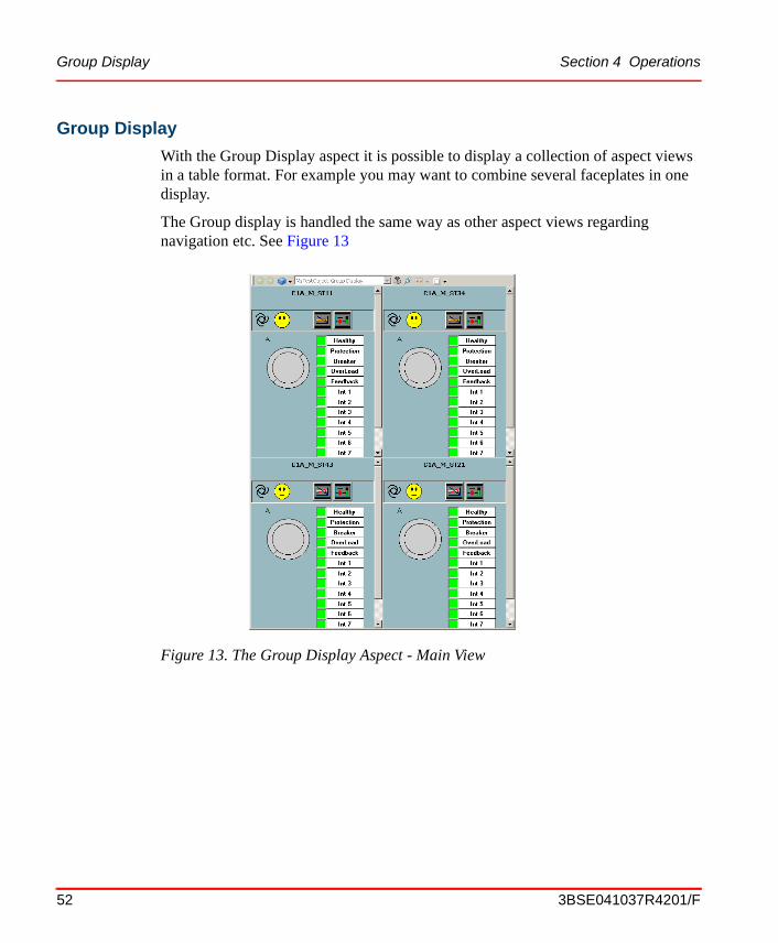
Group Display
With the Group Display aspect it is possible to display a collection of aspect views in a table format. For example you may want to combine several faceplates in one display.
The Group display is handled the same way as other aspect views regarding navigation etc. See Figure 13
Figure 13. The Group Display Aspect - Main View
52 3BSE041037R4201/F

Section 4 Operations Log over
ProductGuideSV4.book Page 53 Tuesday, May 20, 2008 1:47 PM
Log over
The Compact HMI 800 Security model is based on extensions to the Windows security model. The extensions make it possible to set permissions for users or user groups on an Compact HMI 800, a structure or part of a structure, or an Aspect Object.
For example the permission “Operator” gives the rights necessary for the tasks of an operator. As an administrator you have all permissions.
The log over function enables a fast and temporary switch between users in a running workplace. For example if an operation requires a permission not held by an operator, another user (e.g. an administrator) that holds the required permission, can log on to perform that operation. The log over changes the permissions and user roles but keeps all open windows with their present contents. The permitted actions in the open windows are controlled by the permissions of the logged over user.
3BSE041037R4201/F 53

Log over Section 4 Operations
ProductGuideSV4.book Page 54 Tuesday, May 20, 2008 1:47 PM
54 3BSE041037R4201/F

ProductGuideSV4.book Page 55 Tuesday, May 20, 2008 1:47 PM
Section 5 Engineering
OverviewThe major goal for the Compact HMI 800 Engineering suite is to provide maximum engineering performance. To reach this goal, a suite of tools are offered. All tools are integrated and support the Aspect Objects architecture. The tools scale from simple standards-based control configuration tools to software development kits, which enable the use of custom tools to gain performance.
The tools can be applied throughout the plant lifecycle from the design phase into the operation phase maximizing the performance in design and maintenance.
Standard Engineering Tools are to be used by application engineers and maintenance engineers implementing and servicing the control configuration.
Engineering WorkplaceThe set of Standard Engineering Tool is called Engineering Workplace. It consists of the following features:
• Engineering Platform including Bulk Data Manager.
• Graphics Builder.
The Engineering Workplace functionality is available on the Server Workplace.
Engineering Platform including Bulk Data Manager
The Engineering Platform offers the following functionality.
• Use of a powerful designation handling with self adapting designations
3BSE041037R4201/F 55
Graphics Builder Section 5 Engineering
ProductGuideSV4.book Page 56 Tuesday, May 20, 2008 1:47 PM
• Create and maintain your documentation by the integrated Document Manager. The data reference function of Document Manager enables actual data from other applications or actual values of central parameters in all Word, Excel, and AutoCAD documents. Different versions of documents can be stored. Document packages can be created.
• Efficiently manage, view, report and store common plant parameters with the integrated Parameter Manager
Bulk Data Manager
The ability to efficiently manage large amounts of data is a crucial part of any automation system. The Compact HMI 800 meets these requirements through a tight integration with Microsoft® Excel. By using a series of Excel add-ins, the bulk data management features couple the full productivity benefits of Microsoft Excel with Compact HMI 800.
The basic bulk data management functionality allows users to configure a worksheet to read and write aspect and object properties, supporting an iterative analysis and design process. In addition, the bulk data management features allow the import and assignment of external data such as signal lists, tag names or documents. System data can be exported at any time to simplify data validation and modification. The track changes function provides the ability to compare two sets of data in order to identify changes. This function allows users to check for and introduce changes in a controlled manner.
Graphics Builder
Graphics Builder is a tool, which enables configuration of graphic aspects, e.g. graphic displays, graphic elements and faceplate elements. It is a tool built on Visual Basic. Graphics Builder provides several features for configuring graphic aspects, and writing expressions. Even though the Visual Basic environment is a full-fledged programming environment, the configuration of graphic displays of graphic elements does not require programmers to have a Visual Basic background. Graphics Builder allows the full power of Visual Basic if needed. For example the Visual Basic code panes are available and the environment is accessible.
56 3BSE041037R4201/F

Section 5 Engineering Graphics Builder
ProductGuideSV4.book Page 57 Tuesday, May 20, 2008 1:47 PM
The following features are specific to the Graphics Builder.
• Expression Builder that allows you to assign expressions (that is, to specify subscriptions and specify the relationship between the process data and the data that is to be displayed).
• Graphic Libraries dialog which allows you to add Primitives and Sub-elements to your toolbox.
• Element Browser in which you can select to include appropriate graphic elements.
• Design and Test function that enables you to build graphic aspects in design mode and then check their behavior in test mode. Included is also a test data provider.
Figure 14. Graphics Builder
3BSE041037R4201/F 57

Graphics Builder Section 5 Engineering
ProductGuideSV4.book Page 58 Tuesday, May 20, 2008 1:47 PM
• Deploy function which stores the graphic aspects and enables viewing of process displays by process operators. Before a graphic element is deployed, it can only be seen in Graphics Builder.
• Help function that offers you access to On-line Help.
• Graphics wizard that guides you through the steps of building graphic aspects.
• Add Member function that allows you to add properties, methods, and events to a graphic element.
Property elements enable input directly from a graphic to an OPC property.
58 3BSE041037R4201/F
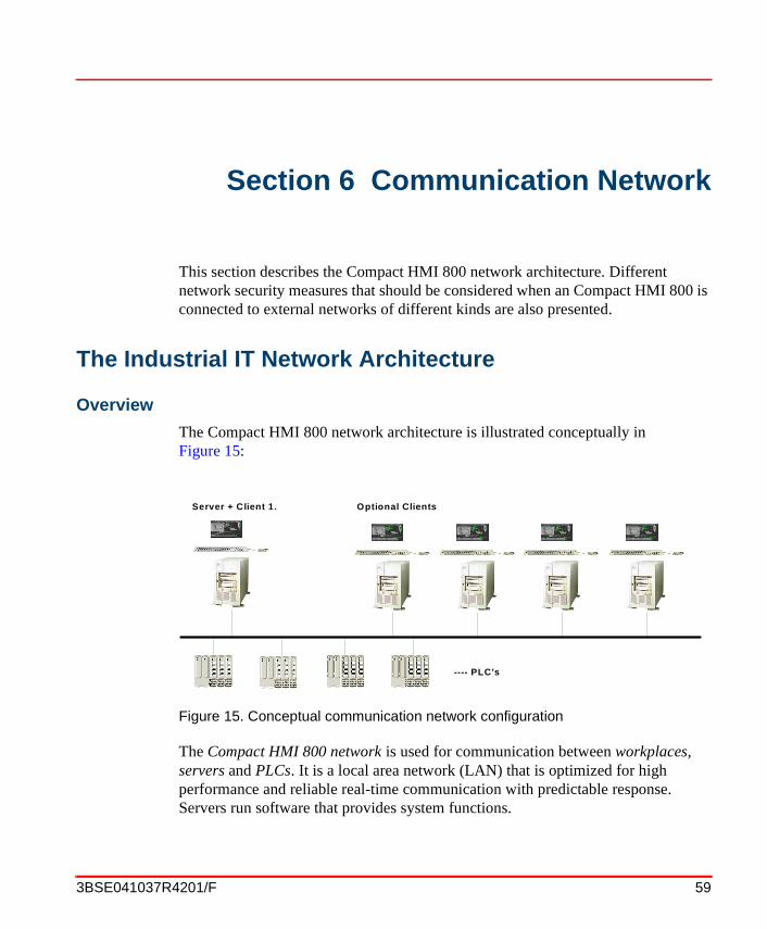
ProductGuideSV4.book Page 59 Tuesday, May 20, 2008 1:47 PM
Section 6 Communication Network
This section describes the Compact HMI 800 network architecture. Different network security measures that should be considered when an Compact HMI 800 is connected to external networks of different kinds are also presented.
The Industrial IT Network Architecture
Overview
The Compact HMI 800 network architecture is illustrated conceptually in Figure 15:
The Compact HMI 800 network is used for communication between workplaces, servers and PLCs. It is a local area network (LAN) that is optimized for high performance and reliable real-time communication with predictable response. Servers run software that provides system functions.
Figure 15. Conceptual communication network configuration
---- PLC's
Optional ClientsServer + Client 1.
3BSE041037R4201/F 59

Overview Section 6 Communication Network
ProductGuideSV4.book Page 60 Tuesday, May 20, 2008 1:47 PM
Workplaces run software that provides various forms of user interaction. Controllers are nodes that run control software.
The automation system network can be connected to a plant network, such as an office or a corporate network, via some form of network isolation device. The nature of this device depends on the nature of the plant network and the level of security that is required for the automation system – it may actually be a set of interconnected computers and devices that cooperate to provide the level of security required in a particular installation. Compact HMI 800 is pre-loaded using a workgroup configuration. Connection to a plant network requires a reconfiguration.
A redundant network is continuously being monitored by the RNRP protocol. All network events, including configuration errors, are reported to the user.
Further connection of the plant network to the Internet or any other type of external network should be performed in accordance with adequate network security practices.
Third party PLCs using other communication standards and protocols may also be connected. The Compact HMI 800 has been tested with a set of protocols
Note that for performance and integrity reasons, direct connection to an automation system network or systems not based on Industrial IT should be avoided.
The automation system network is based on TCP/IP over Ethernet. The routing protocol that is used is RNRP (Redundant Network Routing Protocol). This protocol supports redundant network configurations based on standard network components.
Detection of a network failure and switch over to the redundant network takes less than one second, with no loss or duplication of data. A redundant network consists of two fully separate Ethernets. It works as a standard TCP/IP network, with the addition of RNRP, which works as described in the section below.
Redundant Network Routing Protocol (RNRP)
RNRP is an IPv4 routing protocol developed by ABB. It is specially designed for use in automation networks with limited topology but with high demands on network availability. The protocol has alternative paths between nodes to enable quick reaction on network failures. In Compact HMI 800 only one network is used.
60 3BSE041037R4201/F

Section 6 Communication Network Industrial IT Network Security Considerations
ProductGuideSV4.book Page 61 Tuesday, May 20, 2008 1:47 PM
RNRP handles the node and network supervision. RNRP quickly detects if a node or remote network is down. This information is used to detect if a redundant server is down and whether a new server can be connected.
Each node cyclically sends a routing vector as a multicast message. The routing vector indicates which other nodes this node can see on the network. Each node uses received routing vectors to build a table listing which nodes can be reached on which of the two networks. Routing vectors are distributed with a cycle of 1 second.
The automation system network is a private IP network. IP addresses are static, and must be selected according to a scheme defined by RNRP. Each node has two IP addresses, one on the primary network, and one on the backup network, see IP Address Use on page 66.
Advantages with the RNRP redundancy concept are that it works with standard network devices (hubs, switches or bridges), and that no special Network Interface Cards (NICs) are required.
Industrial IT Network Security Considerations
For more information see the document 3BSE032547, Industrial IT Integrated Automation System - Network Security Consideration in ABB Library.
Security
The security information in this document are provided to you for background information only. Consult your IT Network professional in order to determine your specific implementation. It is the responsibility of the end-customer to have an updated and implemented IT security policy in his process automation.
Firewall
A firewall is a system which main purpose is to control the access to or from a protected network (for example a control network). A correctly configured and maintained firewall ensures that all communications attempting to cross from one network to the other meet an organization's security policy.
There should always be a correctly configured dedicated firewall as the only interconnection-mechanism between the Internet and the ABB process control installation.
3BSE041037R4201/F 61

Firewall Section 6 Communication Network
ProductGuideSV4.book Page 62 Tuesday, May 20, 2008 1:47 PM
Firewalls track and control communications, deciding whether to allow, reject or encrypt communications. In addition to protecting trusted networks from the Internet, firewalls are increasingly being deployed to protect sensitive portions of local area networks and individual PCs. The design of a firewall system should be based on the user’s corporate security policy, therefore it's very important to discuss and investigate this carefully. It should be revised on a regular basis because of the increasing number of resources and applications which are available on the Internet and local networks.A firewall system can be a router, PC, dedicated hardware solution, workstation, one or more servers, or a mix of these, configured to protect a site or subnet from protocols and services that can be abused by hosts outside the subnet. A firewall system is usually located at a higher-level gateway, such as a site's connection to the Internet. However, firewall systems can be located at lower-level gateways to provide protection for smaller collections of servers or subnets.
As of the writing of this document the following types of firewalls exist:
• packet-filtering firewall.
• a circuit level gateway.
• an application level gateway.
• a stateful inspection firewall.
ABB suggests consulting the user’s corporate IT department or consultant to determine which firewall is most appropriate for the user’s installation.
Some popular firewall systems available today include:
• Checkpoint Firewall-1 (http://www.checkpoint.com/).
• Cisco PIX (http://www.cisco.com/).
• Netscreen (http://www.netscreen.com/).
• Nokia Firewall (http://www.nokia.com/securitysolutions/).
When accessing the process control system from the internet, a VPN (Virtual Private Network) must be set up through the firewall. The internet-based computer must be clean, under strict user access control, not used for other purposes and have no other connections to the Internet other than the one used for the VPN connection. The VPN should end in a VPN concentrator placed in the DMZ (Demilitarized Zone) of the firewall.
62 3BSE041037R4201/F

Section 6 Communication Network Virus Risks
ProductGuideSV4.book Page 63 Tuesday, May 20, 2008 1:47 PM
Virus Risks
Do not allow running of non-authorized software on the clients or servers used for process control, or on other PCs connected to any part of the network without a firewall between the network and these other elements.
Use an updated virus scanner to regularly scan the systems for viruses. McAfee VirusScan and NetShield are possible examples. (http://www.mcafee.com/, http://www.nai.com/).
Run all external traffic through the firewall. Set up a virus-scanner for all traffic through the firewall.
Allow only authorized users to log on to the systems. Do not allow guests.
Do not allow users to run the system with an authority level that is different from that for which they have been approved.
Domains
Windows Workgroup
A Windows Workgroup is not managed on a dedicated PC. The workgroup configuration needs to be done on all PCs that belong to the workgroup. This includes handling the names and addresses of the PCs and definition of users and groups. The users and groups need to be created exactly the same way on all PCs in the workgroup and the host names are handled with a host-file that must be the same in all PCs.
There is no fixed limit for the number of nodes or number of users that can be handled within a workgroup, but systems with more than 10 PCs or 5 users are normally easier to manage in a domain.
It is very important that the systems are protected from viruses, trojans and other malicious software.
3BSE041037R4201/F 63

System Servers Section 6 Communication Network
ProductGuideSV4.book Page 64 Tuesday, May 20, 2008 1:47 PM
System ServersAny service (piece of software) can, from an architectural perspective, run on almost any server (logical piece of software) in any server node (physical PC server) in the system. To create simple configuration rules, avoid unsuitable configuration combinations, and to describe, test and verify various supported configurations, definitions for three classes of servers follow. Even though it is in some cases possible to optimize an installation by using other configurations, it is recommended the guidelines given in this section be followed.
• The Aspect server runs the “central” intelligence in the system, including the aspect directory and other services related to object management, names, security, etc. Examples of services that run on Aspect Servers are the Aspect Directory, Structure and Name Server (SNS), Cross Referencing (XRef), and File Set Distribution (FSD).
• The PLC Connect server provides access to controllers and other data sources. Several groups of connectivity servers may exist in a system, each serving one set of data sources. Examples of services that run on a connectivity server are OPC related services (DA, AE, and HDA).
Compact HMI 800 runs using Workgroups.
Server classes are deployed on nodes. A node is a network addressable machine (a PC). For very small installations, one single node (PC) can carry all these server categories as well as the client part(s) of the product(s).
Communication Hardware
Switches and Routers
A Hub is a connection device within a network segment. It is an Ethernet multiport repeater. A hub only allows one message to be transferred at a time between all of its ports. This means that there will be message collisions when more than one node transmits at the same time, just as it used to be with the old coax cables. Collisions are handled by the media access mechanisms of Ethernet, but in a network with heavy traffic the collisions decrease the data throughput and give non-deterministic response times in the network.
64 3BSE041037R4201/F

Section 6 Communication Network Switches and Routers
ProductGuideSV4.book Page 65 Tuesday, May 20, 2008 1:47 PM
A Switch is a more sophisticated type of hub.
It filters and forwards frames based on the destination address of each frame.
A switch eliminates most of the message collisions caused by several nodes transmitting at the same time. This is basically accomplished by queueing messages per port and by allowing several point-to-point messages to be transferred simultaneously, if they go between different pairs of ports. This means that a network using switches will allow a much higher throughput than a network using hubs and it does not have the same problem with non-deterministic response times.
Switches that only store and forward ethernet packets without being accessible as nodes on the network are called un-managed switches.
Switches that act as a node with an IP address on the network giving access to network management information are called managed switches. The network management information is for example configuration data for the different ports regarding port speed and status information about number of bytes transferred, check sum errors etc. The amount of management information may differ very much between different switch types.
The actual ethernet packet switching function is often the same for managed and un-managed switches. These are some pros and cons for managed and un-managed switches:
• Un-managed switches are typically cheaper.
• Managed switches give the possibility to supervise the network better.
• Managed switches may give possibilities to control the traffic better by e.g. address based traffic filtering.
• In a small network the additional features of a managed switch may be unnecessary.
• In a large network the additional features of a managed switch may be very useful.
For the Compact HMI 800 we recommend the use of un-managed switches or hubs.
3BSE041037R4201/F 65
Network Cables Section 6 Communication Network
ProductGuideSV4.book Page 66 Tuesday, May 20, 2008 1:47 PM
Network Cables
In industrial environments optical Ethernet cables are preferred.
Switches having both optical and electrical interfaces can be used between the two media types.
Within a cabinet, or within a control room where there are no unsuppressed loads or other disturbances, shielded, twisted pair cables (cat5 or cat6) can also be used.
Network Performance
The number of nodes in one control network is limited to five, due to limited routing resources in the controllers, and to the load generated from RNRP in the controllers. RNRP provides a redundancy changeover time of ca 1 s.
For larger installations, the controllers should be placed on separate Control Network areas with the connectivity servers as routers.
It is recommended to use 100 Mbit/s switched fast Ethernet communication between clients and servers. Controllers use 10Mbit/s, and should be connected via switches to 100 Mbit/s backbones.
IP Address Use
The nodes (clients, servers and controllers) in the control network should use the IP v4 private address range 172.16.x.x, or 172.20.x.x, or 172.24.x.x, or 172.28.x.x, as RNRP requires dual sequential address ranges. The sub-net mask should be 255.255.252.0.
If connection and routing to a plant network is required using an other IP address range, a router should be used in between.
66 3BSE041037R4201/F

ProductGuideSV4.book Page 67 Tuesday, May 20, 2008 1:47 PM
Section 7 System Management
Product InstallationThe Compact HMI 800 software is delivered pre-installed on a PC and with a license according to the order. The license is required to unlock features for operating or engineering the system.
Updates and security related software from non-ABB companies must be downloaded and installed separately, as guided from the Automated Installation program.
PC HardwareThe Compact HMI 800 is verified in a limited number of configurations, PC types, and brands. Only one PC type is available today. The tested machine is specified for reference, a minimum configuration, and recommended requirements on the PC. Windows compliance (processor speed, RAM size, free space on hard drive, free PCI slots, service packs, versions, etc.) are specified in product data.
Third Party SoftwareThe Compact HMI 800 and its features require that a number of third party software products are installed. The requirements are indicated per Core Functional Area or by node type, but are also summarized in the document 800xA Third Party Software 3BSE039230, that can be found in ABB Library.
3BSE041037R4201/F 67

Diagnostics Collection Tool Section 7 System Management
ProductGuideSV4.book Page 68 Tuesday, May 20, 2008 1:47 PM
Diagnostics Collection ToolThe ABB Diagnostics Collection Tool is part of the Compact HMI 800 and is used to collect diagnostics information, for support and trouble shooting purposes, from any node (or nodes) in the system, local and/or remote.
The ABB Diagnostics Collection Tool is part of the Compact HMI 800 and is installed on all computer nodes in the system. Communication between nodes is via DCOM. The data collected, typically for later analysis, is packaged into compressed cabinet (.cab) files which are combined with a short description (entered by the user) of the reason for collecting the data, the surrounding circumstances, and other relevant information.
Figure 16. The ABB Diagnostics Collection Tool
68 3BSE041037R4201/F

Section 7 System Management Supported Products
ProductGuideSV4.book Page 69 Tuesday, May 20, 2008 1:47 PM
The overall purpose of the tool is to unify, and make consistent, the information gathering process for all ABB Industrial IT products regarding necessary information from installations at customer sites. This will help speed up the problem resolution process.
The main functions of the tool are:
• Gather diagnostics data from nodes in a distributed system.
• View the gathered data to facilitate analysis.
Supported Products
The ABB Diagnostics Collection Tool for Compact HMI 800 product supports:
• Core System and Operation
• Central Licensing
• PLC Connect
• Softpoint Server
The Diagnostics Collection Tool runs on the following operating system:
• Windows XP
Industrial IT Related Functions
Core System and Operation Diagnostics Data
This plug-in collects log files generated by the Core System and Operation.It collects data generated by Applog and System events.
• AfwConfigWizard.log
Lists all loaded files upon creation and startup of a system.
• System Messages
A system message is intended for a user of the system.
• Applog
Application log (Applog) is the primary debug and diagnostics tool of Compact HMI 800. The tool supports logging and state ´report´ operations.
3BSE041037R4201/F 69

Industrial IT Related Functions Section 7 System Management
ProductGuideSV4.book Page 70 Tuesday, May 20, 2008 1:47 PM
Control OPC Server Diagnostics Data
This plug-in collects log files generated by the Control OPC Server.
• Session Log Files
The OPC Server for AC 800M automatically creates a Session log file on the hard disk at start-up. This file contains information generated during one session, i.e. from the time the product is started until it is stopped. A new file will be created upon each new start-up.
At start-up, information about the hardware and software versions, and later, information on system events, such as mode changes and error printouts, are logged in the Session log. The log is continuously updated in a running system, and whenever a problem occurs it is a good idea to look at the log to see if there are any printouts.
• Heap Statistics Log
Every time a message “memory full” occurs in OPC Server, the system software will automatically generate a Heap Statistics log file containing information about the content of the heap.
Compact Control Builder Diagnostics Data
The following log files are available:
• System Log File
The System log is created the first time Compact Control Builder is started and is used to store general information concerning Compact Control Builder. Examples of information logged are starting/stopping of Compact Control Builder, users logging on and out, changes in system privileges and changes in the setup of Compact Control Builder made in the Tools menu.
• Session Log Files
See Session Log Files description in Control OPC Server Diagnostics Data on page 70.
70 3BSE041037R4201/F

Section 7 System Management Industrial IT Related Functions
ProductGuideSV4.book Page 71 Tuesday, May 20, 2008 1:47 PM
• Start Log
Compact Control Builder creates a Start log file for logging the last offline to online transfer. Information, such as warnings and error messages, will be logged. The Start log is very useful when investigating errors that may occur during or just after an Offline -> Online transition. Sometimes the start log will give a natural explanation of what at first looks like an error (e.g., lost Cold Retain values).
• Heap Statistics Log
Heap Statistics Log description in Control OPC Server Diagnostics Data on page 70.
• Controller System Logs
The controller AC 800M has a circular log buffer (size 16 kb) that can hold a certain amount of information, normally all information that has been generated during the last 5-8 start-ups. The Controller System log is never deleted, provided that the battery backup, to retain the information during power failure is working properly. This function makes it possible to restart a faulty system immediately to regain control of the process, without loosing vital information about the error.
• System Information Report
The System Information Report is a list of hardware, software and setup information for an engineering station. This information is generated by a menu command and presented in a text editor.
3BSE041037R4201/F 71

Industrial IT Related Functions Section 7 System Management
ProductGuideSV4.book Page 72 Tuesday, May 20, 2008 1:47 PM
License Usage Overview in a Running Compact HMI 800
An overview of the available licenses and the usage of the licenses are given by the "License Usage" aspect. This overview is available by adding this aspect to e.g. the root object in the system. The aspect is shown in the Figure 17 below.
The aspect shows both the delivered features (Total) and the actual usage (In Use) of the features.
Plug-ins
Central Licensing
This plug-in collects information related to Central Licensing, including available and used licenses.
Production Management
This plug-in collects system log files generated by Production Management.
PLC Connect & Softpoint Server
This plug-in collects system log files generated by PLC Connect and Softpoint Server.
Figure 17. License Usage overview
72 3BSE041037R4201/F
Section 7 System Management Microsoft Related Functions
ProductGuideSV4.book Page 73 Tuesday, May 20, 2008 1:47 PM
Microsoft Related Functions
Installed Software Version Information
This plug-in lists the versions of all installed software, including Industrial IT Compact HMI 800 products.
Dump Registry Data
This plug-in dumps the registry data, either the complete registry or for ABB software only.
SQL Diag
SQLDiag gathers diagnostics and current state information within SQL server and stores it in a readable file.
This utility can be run anytime, whether or not SQL Server is started.
Dr. Watson
Dr. Watson is an error-handling application for Windows systems. It detects and diagnoses program errors, then logs the resulting diagnostic information. The drwtsn32.log and the user.dmp files maintain the diagnostic information.
MS Windows Task Manager
TaskMgr examines the system memory load and shows a synopsis of the processes and applications running on a system. It indicates the total physical memory, the free memory, and the amount used by the cache as well as the most commonly used performance measures for processes.
MS Windows Service Information
Service Information gathers information about a target server running Windows, such as server name, version, domain, drive information, services and state, and system up time. There are three options available: Show Service and Service Drivers, Get Version Info, and Show Shares.
MS Windows Process Information List
Process List shows information from all the processes that are currently running on a system. This information includes the time of execution, amount of time the process has executed in user and kernel modes, and the amount of physical memory the OS has assigned the process.
3BSE041037R4201/F 73
Microsoft Related Functions Section 7 System Management
ProductGuideSV4.book Page 74 Tuesday, May 20, 2008 1:47 PM
• Threads
Shows statistics for all active threads on the system.
• Memory Detail
Shows memory-oriented information for each process, rather than the default of CPU-oriented information.
• Processes, Memory, Threads
Shows CPU, memory and thread information for each of the processes specified.
• Process ID
Instead of listing all of the running processes in the system, this parameter narrows the scan to those processes that begin with the name of the process or match a specific process ID.
Process ID numbers can be obtained from the PID column of the Task Manager.
MS Windows System Event Logs
System Event Log records system and hardware events as log entries on a server. Application, security, and system event logs may be viewed.
• Application Events log
The application log contains events logged by applications or programs.
• Security Events log
The security log can record security events such as valid and invalid logon attempts as well as events related to resource use such as creating, opening, or deleting files. An administrator can specify what events are recorded in the security log.
• System Events log
The system log contains events logged by the Windows system components. For example, the failure of a driver or other system component to load during startup is recorded in the system log. The event types logged by system components are predetermined by Windows.
74 3BSE041037R4201/F

Section 7 System Management Microsoft Related Functions
ProductGuideSV4.book Page 75 Tuesday, May 20, 2008 1:47 PM
MS Windows User Dump
User Dump displays a list of all running processes and their process IDs recorded in a text file called User Dump.txt. User dump can capture the state of a process and can be very useful when troubleshooting servers that have stopped responding and unresponsive processes.
MS Windows Handle List
Handle List is a utility that displays information about open handles for any process in the system. You can use it to see the programs that have a file open, or to see the object types and names of all the handles of a program.
MS Windows DLL List
ListDLLs is able to show you the full path names of loaded modules - not just their base names. In addition, ListDLLs will flag loaded DLLs that have different version numbers than their corresponding on-disk files (which occurs when the file is updated after a program loads the DLL), and can tell you which DLLs were relocated because they are not loaded at their base address.
3BSE041037R4201/F 75

Microsoft Related Functions Section 7 System Management
ProductGuideSV4.book Page 76 Tuesday, May 20, 2008 1:47 PM
76 3BSE041037R4201/F

ProductGuideSV4.book Page 77 Tuesday, May 20, 2008 1:47 PM
Section 8 Technical Data and Performance
Compact HMI 800 CapabilitiesThe Compact HMI 800 is scalable both in functionality and size. The rules for how the system can be configured depends on how functionality is combined in different node types, and on the system and application size. This chapter defines these combinations and rules for Compact HMI 800 SV 4.1.
Servers and Clients
Different system functions are provided by different types of nodes in a Compact HMI 800 installation. A node in this context is a computer (PC) that has a network address on the Compact HMI 800 network, used as a server, or as a client.
Basic Node Types
The basic node types are:
• Aspect Server - runs the ‘central’ intelligence in the system, including the aspect directory and other services related to object management, object names and structures, security etc.
The Aspect Server and PLC Connect connectivity server are delivered pre-installed in one node.
• Client - runs workplace functionality, such as operator and engineering workplaces.
Server Based Clients
All node types include client functionality. These clients are referred to as server based clients.
3BSE041037R4201/F 77

Compact HMI 800 Dimensioning Section 8 Technical Data and Performance
ProductGuideSV4.book Page 78 Tuesday, May 20, 2008 1:47 PM
Compact HMI 800 Dimensioning
Signal and Tag Calculation
The server and clients are scaled based on signals and tags.
• A Signal is any aspect object of the type PLC xx Signal Type, where xx defines the type of signal. Each signal represents a value that is read or written from or to a controller, PLC or other external device connected to Compact HMI 800.
• A Tag is any Aspect Object that has one or more Faceplate Aspects attached.
Configuration Rules
Network Configuration
The maximum number of nodes (PC nodes and controllers) in one control network area is given in Table 6. The limitation is primarily due to the load generated from RNRP in the controllers in the control network. This will give a redundancy changeover time of ca 1 s.
For larger systems a split into separate Client/Server and Control networks is recommended, if needed with several control network areas (see The Industrial IT Network Architecture on page 59). The maximum number of (PC) nodes on a client/server network is stated in Table 6.
It is recommended to use 100 Mbit/s switched, fast Ethernet communication between clients and servers. Controllers use 10 Mbit/s, and should be connected via switches to 100 Mbit/s backbones.
History Logs
The history function in Compact HMI 800 is storing the data on the C-disk in the server workplace. The disc space and the number of logged items/second is limited. The following basic rules applies.
Max number of logged, time stamped values, stored per second are 500 in the server.
78 3BSE041037R4201/F

Section 8 Technical Data and Performance Configuration Rules Summary
ProductGuideSV4.book Page 79 Tuesday, May 20, 2008 1:47 PM
Max number of time stamped values stored are 600.000.000 in a server, this consumes 120GB Disk space.
Max number of logs continuously running (primary and secondary) in a server is 2000.
The following sample calculation shows how to calculate the maximum period for which the server can store historical data:
- LS (Logged Signals): Number of signals retrieved from the controllers and storedcyclically in the server.
- CT (Cycle Time): Time between each sample in seconds.
- LT (Logged Time): The length of the history log.
LT = 600.000.000 * CT / (LS*3600*24*365) Years
Example:
LS=500
CT= 10 min
=> LT = 600.000.000*10 / (500*60*24*365) = 22.8 Years
If we are logging 500 Signals every 10 minutes values can be stored for 22 Years.
Configuration Rules Summary
The following table details the limits in system and application size.
Table 6. System Configuration limits
Parameter (max numbers) Compact HMI 800 with server based client
Signal/(Tags) 5000/(2000)
Client nodes 5 (including server based clients)
Engineering Clients 1 (server based)
PLC Connect connectivity server One included in the Operator Workplace Server
History logs 250
3BSE041037R4201/F 79

Available Functions Section 8 Technical Data and Performance
ProductGuideSV4.book Page 80 Tuesday, May 20, 2008 1:47 PM
Available Functions
The Compact HMI 800 offering is extensive and flexible. In the “System Capacity and Performance Data” section guidelines are given, such as PC requirements, capacity, limits, and technical configuration rules.
In addition to this information, some system guidelines have been stated, during verification and validation, to make the ordering easier, to avoid unsuitable combinations of options, etc.
Table 7: Available Functions with PLC Connect
Licensed Functions Comments
Operator Workplace Server Must always be selected
Operator Workplace (Client) 1 license required for each running client
Engineering Workplace - Rich Client
50, 500, 2500 signals Some must always be selected
PLC Connect Dial-Up Can only be combined with AC 800M Connect
Audit Trail
Advanced Access Control
SMS and e-mail Messaging
Calculation Engine
Excel Based Reporting Requires Operator Workplace.
80 3BSE041037R4201/F
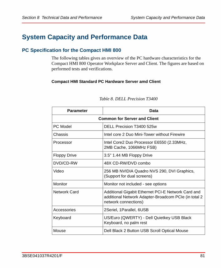
Section 8 Technical Data and Performance System Capacity and Performance Data
ProductGuideSV4.book Page 81 Tuesday, May 20, 2008 1:47 PM
System Capacity and Performance Data
PC Specification for the Compact HMI 800
The following tables gives an overview of the PC hardware characteristics for the Compact HMI 800 Operator Workplace Server and Client. The figures are based on performed tests and verifications.
Compact HMI Standard PC Hardware Server amd Client
Table 8. DELL Precision T3400
Parameter Data
Common for Server and Client
PC Model DELL Precision T3400 525w
Chassis Intel core 2 Duo Mini-Tower without Firewire
Processor Intel Core2 Duo Processor E6550 (2.33MHz, 2MB Cache, 1066MHz FSB)
Floppy Drive 3.5" 1.44 MB Floppy Drive
DVD/CD-RW 48X CD-RW/DVD combo
Video 256 MB NVIDIA Quadro NVS 290, DVI Graphics,(Support for dual screens)
Monitor Monitor not included - see options
Network Card Additional Gigabit Ethernet PCI-E Network Card and additional Network Adapter-Broadcom PCIe (in total 2 network connections)
Accessories 2Seriel, 1Parallel, 6USB
Keyboard US/Euro (QWERTY) - Dell Quietkey USB Black Keyboard, no palm rest
Mouse Dell Black 2 Button USB Scroll Optical Mouse
3BSE041037R4201/F 81

PC Specification for the Compact HMI 800 Section 8 Technical Data and Performance
ProductGuideSV4.book Page 82 Tuesday, May 20, 2008 1:47 PM
Supported Operating SystemCompact HMI 800 SV 4.1 is supported by the following operating system:
- Windows XP Professional for clients and server.
Operating System Microsoft® Windows® XP Professional (SP2)
Sound Card Standard Integrated
Base Service 3 years NBD onsite Technical Support (Direct Countries only)
Account Management GCP Std Service
Additional for the Server
Memory 2.0GB 880MHz NON-ECC DDRll Memory (2x1 GB)
Hard Drive 1 160GB SATA 3.0Gb/s with NCQ and 8MB DataBurst
Hard Drive 2 250GB SATA 3.0Gb/s with NCQ and 8MB DataBurst Cache
Office SW Microsoft Office 2003 Professional
License Dongle Compact HMI 800 only support Dongle based licensing
Additional for Client
Memory 1.0 GB 800MHz NON-ECC DDRll Memory
Hard Drive 80 GB SATA, 7200 RPM Hard Drive with 8MB DataBurst CacheTM
Service and Support
For service see: http://www.dell.com/us/en/gen/services/service_service_contracts.htm
For support see: http://www1.us.dell.com/content/topics/global.aspx/services/en/nbd?c=us&cs=555&l=en&s=biz#tn1
Table 8. DELL Precision T3400
Parameter Data
82 3BSE041037R4201/F

Section 8 Technical Data and Performance PC Specification for the Compact HMI 800
ProductGuideSV4.book Page 83 Tuesday, May 20, 2008 1:47 PM
Compact HMI Industrial PC Hardware Server and Client
Table 9. Industrial Computer IPC-7220
Parameter Data
Common for Server and Client
PC Model Industrial Computer IPC-7220
Chassis IPC, rack mounting kit available
Processor Industrial motherboard with Intel Core2Duo 2.13 GHz 800MHz FSB
Floppy Drive 3.5" 1.44 MB Floppy Drive
DVD/CD-RW DVD-RW (CD X48, DVD x16)
Video PCI-E 128 MB (Matrox QID-E128LPAF Quadruple),
(Support for dual screens)
Monitor Monitor not included - see options
Network Card Dual LAN , 1 GB, RJ45
Accessories 4 serial and 1 parallell port in backpanel
Keyboard KB US IP65
Mouse MS mouse
3BSE041037R4201/F 83

PC Specification for the Compact HMI 800 Section 8 Technical Data and Performance
ProductGuideSV4.book Page 84 Tuesday, May 20, 2008 1:47 PM
Environmental Specification
Temperature:0 - 40 Co (operating)-20 - 60 Co (non-operating)
Humidity:10 - 85% @ 40Co non-condensing (operating)10 - 95% @ 40Co non-condensing (non-operating)
Vibration:5 - 17 Hz 1,27 mm p-p (operating)5 - 17 Hz 2,54 mm p-p (non-operating)17 - 500 Hx 1G (operating)17 - 500 Hz 2G (non-operating)
Shock.10G/with 11 ms duration, half sine vawe (operating)20G/with 11 ms duration, half sine vawe (non-operating)
Altitude:0-3.048 m (10.000 feet)
EMC:Fullfills EMC requirements; Emission Office, Immunity Industry Tested acc to: EN 61000-6-3:2001, EN55022:1998, -A1:2000 A2:2003 Class B, EN 61000-3-2:2001 for Emission Tested acc to EN 61000-6-2:2005, SS-EN 55024:1998 +A1:2001 +A2:2003, EN 61000-4-2, -3, -4, -5, -6, 11
CE-certificate by SWEDAC Accredited Laboratory
Operating System Microsoft® Windows® XP Professional (SP2)
Sound Card Integrated Sound Blaster Compatible Sound (AC97 Audio)
Warranty 2 years from date of delivery
Account Management GCP Std Service
Table 9. Industrial Computer IPC-7220
Parameter Data
84 3BSE041037R4201/F
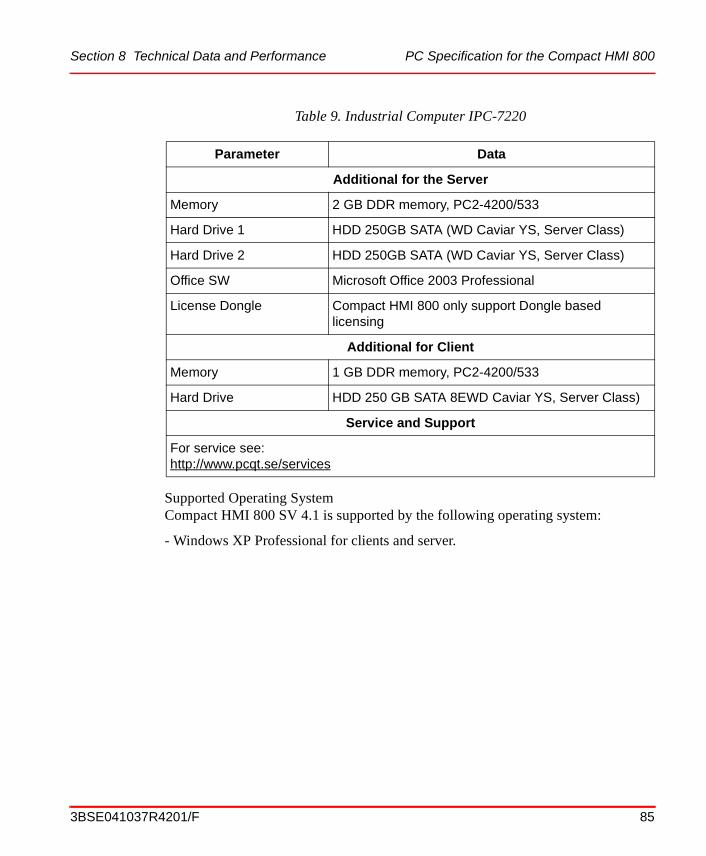
Section 8 Technical Data and Performance PC Specification for the Compact HMI 800
ProductGuideSV4.book Page 85 Tuesday, May 20, 2008 1:47 PM
Supported Operating SystemCompact HMI 800 SV 4.1 is supported by the following operating system:
- Windows XP Professional for clients and server.
Additional for the Server
Memory 2 GB DDR memory, PC2-4200/533
Hard Drive 1 HDD 250GB SATA (WD Caviar YS, Server Class)
Hard Drive 2 HDD 250GB SATA (WD Caviar YS, Server Class)
Office SW Microsoft Office 2003 Professional
License Dongle Compact HMI 800 only support Dongle based licensing
Additional for Client
Memory 1 GB DDR memory, PC2-4200/533
Hard Drive HDD 250 GB SATA 8EWD Caviar YS, Server Class)
Service and Support
For service see: http://www.pcqt.se/services
Table 9. Industrial Computer IPC-7220
Parameter Data
3BSE041037R4201/F 85

Core System Section 8 Technical Data and Performance
ProductGuideSV4.book Page 86 Tuesday, May 20, 2008 1:47 PM
Core System
Scheduling Service
The maximum scheduling capacity is 200 simultaneous jobs per scheduling server.
Softpoint Service
The Softpoint Server can have up to 2500 softpoint objects. Each softpoint object can have up to 100 signals; however, the total number of signals cannot exceed 25,000.
CPU time for each read or write transaction is one millisecond. The Softpoint server can write 10 events per second to platform-based Aspect Objects.
Events
The disk space requirements for event storage is:
• Storage per numeric history value stored: 21 bytes
• Storage per message: 260 bytes
The Event burst capacity is shown in Table 10.
Table 10. Event burst Capacity
Parameter AS+CS+(AO) with server based client
Continuos alarm throughput/second 20
Event burst (events per 100ms) applied to one Controller
200
Event burst (events evenly distributed over controllers)
600 total over 3 sec.
Event burst recovery time, 1000 events evenly distributed
60 sec.
86 3BSE041037R4201/F

Section 8 Technical Data and Performance Core System
ProductGuideSV4.book Page 87 Tuesday, May 20, 2008 1:47 PM
Calculations
OPC Performance
The capacity for number of OPC-items/second to an OPC Client (800xA OPC Client Connection) is shown in Table 12.
Table 11. Calculations Parameters
Parameter Description
OPC Base Rate Rate at which input variables are updated by their respective OPC data sources.
Range: 100 milliseconds to 1 hourDefault: 1000 milliseconds (1 second)
Cycle Base Rate Rate at which the Calculations Scheduler scans the list of cyclically scheduled calculations. Range: 100 milliseconds to 1 hour Default: 500 ms (1/2 second)
Number of calculations that may be queued waiting to be executed
10,000 Maximum
Execution Rate 100 calculations/second, see write transaction rates specified below to determine capabilities
Number of Calculation Services 10
Write transactions/second The Calculation server can write up to 10 values/second to process (AC 800M) objects.
Write transaction/second to softpoints
The Calculation server can write up to 100 values/second to process softpoint objects
Table 12. Number of OPC-items/second to an OPC Client
Parameter Compact HMI 800
Number of OPC-items/second via afw OPC 25
3BSE041037R4201/F 87

Control Network Clock Synchronization Section 8 Technical Data and Performance
ProductGuideSV4.book Page 88 Tuesday, May 20, 2008 1:47 PM
Control Network Clock Synchronization
Table 13. Control Network Clock Synchronization
Type of Clock Synchronization Accuracy per node
High Precision SNTP 1 ms
SNTP 200 ms
CNCP (between AC 800M) 1 ms
CNCP (AC 800M to AC 800C/Advant Controller 250) 200 ms
CNCP (AC 800M to PPA) 200 ms
88 3BSE041037R4201/F

ProductGuideSV4.book Page 89 Tuesday, May 20, 2008 1:47 PM
Section 9 Ordering and Licensing
GeneralOne of the goals of this product guide is to help sales representatives when ordering the Compact HMI 800 and its licenses.
This section describes the price lists needed when ordering and provides ordering examples.
However, it is outside the scope of this product guide to give a complete description of all ordering procedures and tools, as well as licensing conditions for other Industrial IT products. Each sales representative is assumed to know how to use price lists, pricing and ordering tools to order.
In order to offer market-appropriate functions & features, structure and pricing, the product is divided in server and client functions. In addition the system is scaled on signals and tags. The number of signals is calculated as the number of signals fetched from the connected controllers, PLCs or other external devices or systems. The number of tags is calculated as the number of aspect objects in the system with more then one faceplate aspect. To simplify the scaling, packages that includes both signals and tags are available. In general a package includes 2.5 signals for each tag.
Note that the server always has to be purchased together with a package of at least 50 tags.
In addition to scaling of signals and tags, the system is scaled based on the number of Workplace clients, to further optimize the product for a specific application. Information about tags and how to calculate them are described in Signal and Tag Calculation on page 78.
Use of the Compact HMI 800 software presupposes that a corresponding licensing is purchased. Any use of the Compact HMI 800 software requires at least one Operator Workplace Server license.
3BSE041037R4201/F 89

Price List Structure Section 9 Ordering and Licensing
ProductGuideSV4.book Page 90 Tuesday, May 20, 2008 1:47 PM
Price List StructureThe Compact HMI 800 offering is described in the Industrial IT Compact HMI 800 SV4.1 Price Book, 3BSE040017/B. It consists of a number of price lists. See Table 14, Compact HMI 800 version 4.1 Price Lists on page 90.
The price lists and the selling tools have information about purchasable items. Please refer to them for more information.
Note that multiple items in the price lists are required if you need more tags than what is given in one item.
The complete Compact HMI 800 version 4.1 is comprised of the following price lists:
Information about export control conditions are given in the document 3BSE035412, Export Control Conditions for the Industrial IT System 800xA Software. It is available in the System 800xA Price Book.
User DocumentationUser Documentation is available on the Compact HMI 800 delivery media only.
LicensingA license is required to use licensed ABB software. The SW included in Compact HMI 800 is delivered together with a license that gives the user that right to use the SW. The product also includes 1 year subscription on ABBs Sentinel software maintenance program. This gives the user free upgrades of the software during this period. The period starts at the date of shipping from the factory. The Sentinel agreement can be extended by purchasing the sentinel extension pricelist items.
Table 14. Compact HMI 800 version 4.1 Price Lists
Price List Identity Price List Name
3BSE040680 Compact HMI 800 SV4.1
3BSE040708 Compact HMI 800 SV4.1 Expansion
90 3BSE041037R4201/F
Section 9 Ordering and Licensing Software updates
ProductGuideSV4.book Page 91 Tuesday, May 20, 2008 1:47 PM
Software updates
To get access to software upgrades the license owner needs to register as an owner of the license. Information about how to register is delivered together with the software. After registration software updates and product information accessible on the internet.
End User Runtime Licenses
Ordering is made from the price lists and performed as described in Ordering on page 91.
Licenses and license keys are delivered with the product. Extension of the system can be ordered and downloaded from Software Factory, using the Software Factory Web site http://softwarefactory.abb.com, by local ABB personnel, who provide the customer with the license information, or in special cases directly by the customer. An optional way to retrieve the license information is to send a license application form to the supplying delivery center.
The SoftCare support is described in Software Maintenance on page 91.
Ordering When ordering a Compact HMI 800, use the price list and available ordering tools.
Sales Configurator Wizard for Compact HMI 800
Now a sales wizard for Compact HMI 800, "Wizard Compact Products 800" is available for download. The 800xA Sales configurator Wizard does not support Compact HMI 800.
Software Maintenance
Software Management Program Sentinel combines a software subscription service with basic software support (access to SolutionsBank Foundation).
The Sentinel agreement does not however include:
- HW and Media Preparation for Compact HMI 800.
- 3rd party software upgrades.
3BSE041037R4201/F 91

Software Maintenance Section 9 Ordering and Licensing
ProductGuideSV4.book Page 92 Tuesday, May 20, 2008 1:47 PM
The purchase of additional software options as an extension to an existing license is handled in the same way as the initial software order. The Sentinel agreement is connected to the base license, so the extension of a license does not extend the Sentinel agreement period.
Software Upgrade
Upgrade of the software in the Comapct HMI 800 is done in two ways.
1. For minor upgrades roll-ups and service packs, the software is available for download in ABB library.
2. New releases of the software will be available as purchasable items for a preparation and media fee. The cost for the license upgrade of the software is included in the softcare agreement.
Roll-ups and service packs
Roll-ups and service packs are installed on top of the software delivered according to the instructions included with the packages. Normally this requires a shutdown and restart of each computer.
New Software releases
New major releases of the software is delivered as ghost images containing the same contents as the delivered images without the system data. The upgrade is done according to the upgrade instructions delivered with the upgrade. This basically includes loading the computer with the new image and restoring the system and other added configuration data.
Normally this includes the following steps:
Server Workplace.
1. Backup of the system on the server,
2. Backup of configuration data for Controller configurations
3. Backup of data for added 3rd party software like OPC servers etc.
4. Computer shutdown and restore from delivered upgraded Ghost image
5. Installation of additional 3rd party software
92 3BSE041037R4201/F

Section 9 Ordering and Licensing Life Cycle Policy
ProductGuideSV4.book Page 93 Tuesday, May 20, 2008 1:47 PM
6. Make additional adaptations like IP addresses etc.
7. Restore of data for controller configuration
8. Restore of data for 3rd party software
9. Restore of system backup on the server
10. Make a Ghost dump of the computer
11. Restart of computer
Client Workplaces
1. Backup of data for added 3rd party software.
2. Computer shutdown and restore from delivered upgraded Ghost image
3. Installation of additional 3rd party software
4. Make additional adaptations like IP addresses etc.
5. Restart of computer
Life Cycle PolicyProduct versions are tied to separate price lists. This means the version delivered is controlled by which price list it was ordered from.
The software for a product version is actively maintained as long as the product version is actively sold - the version is in an active phase. When a new major version is released, the previous major version is still supported for a number of years. This means critical errors will be corrected, service packs may be planned, and Microsoft security updates will be verified. There will be no updates as to what operating system the version is running on.
After the supported period the version becomes retired. It may still be possible to do corrections to a retired product version. Such maintenance is normally charged for.
Eventually, when a product version is no longer possible to maintain, for technical and/or economical reasons, it will become obsolete.
At revisions (service packs) the replaced revision will normally go immediately into retired phase. However, this policy will not be put in place until it is possible to upgrade to the next revision without shutting down the system.
3BSE041037R4201/F 93

Life Cycle Policy Section 9 Ordering and Licensing
ProductGuideSV4.book Page 94 Tuesday, May 20, 2008 1:47 PM
94 3BSE041037R4201/F

Index
ProductGuideSV4.book Page 95 Tuesday, May 20, 2008 1:47 PM
INDEXA
Advanced Access Control 36Alarm and Event 27Aspect 12Aspect Objects 13Aspect Objects Architecture 11Aspect Servers 64Audit Trail 36Authority 30
BBulk Data Manager 56
CCalculation Engine 40Compatibility Policy 91Connectivity Servers 64Core System 23cycle base rate 87
DDisplay Call-up 47
Ee-mail Messaging 38Engineering 55Engineering Platform 55Export of Application 33
FFDA 21 CFR part 11 Support 34Firewall 61
GGraphics Builder 56
HHot Keys 49
IImport of Application 33Ingegration of Previously Released Systems 22IP address 66
KKey Benefits 19
LLicensing 90
OOPC base rate 81, 83, 87Operations 43Operator Workplace
Client 43Faceplates 45Layout 44Navigation 48
Ordering 91Ordering Guidelines 80
PPC Hardware 67Price List Structure 90Product Installation 67
RRelated Product Guides 18Report Services 41Routers 64
3BSE041037R4201/F 95

Index
ProductGuideSV4.book Page 96 Tuesday, May 20, 2008 1:47 PM
SSecurity 30SMS Messaging 38Softpoint Server 41Software Maintenance 91Switch 64System 9System Servers 61System Topology 61
TTag Calculation 78Terminology 13Trend Logs 38
UUser Documentation 90User Log-over 36User Re-authentication 36
VView of Audit Logs 36VPN 62
3BSE041037R4201/F 96

ProductGuideSV4.book Page 97 Tuesday, May 20, 2008 1:47 PM

3BSE041037R4201/F. Printed in Sweden February 2008Copyright © 2005- 2008 by ABB. All Rights Reserved® Registered Trademark of ABB.™ Trademark of ABB.
Automation Technology ProductsMannheim, Germanywww.abb.de/controlsystems
Automation Technology Products Wickliffe, Ohio, USAwww.abb.com/controlsystems
Automation Technology ProductsVästerås, Swedenwww.abb.com/controlsystems
http://www.abb.com
ProductGuideSV4.book Page 98 Tuesday, May 20, 2008 1:47 PM