COMPACT CK Technical Manual - schneider-electric.com · The interchangeability makes rating ... 15...
41
Compact CK technical manual molded case circuit breakers 400 -1200A MERLIN GERIN GROUPf SCHNEIDER
Transcript of COMPACT CK Technical Manual - schneider-electric.com · The interchangeability makes rating ... 15...

Compact CK technical manual
molded case circuit breakers 400 -1200A
~ MERLIN GERIN
GROUPf SCHNEIDER

Compact CK circuit breakers table of contents
molded case circuit breakers
Introduction standard compliance additional tests rstings Interrupting capability
advantages
description stanclard and high interrupting rabng circuit breakers current limiting circuit Dreakers I. and F'1 curves
t rip unit characteristics STR 25DP STR 45SP STR 55UP neutral sensor zone selec1ive inter10cking load monitoring lault and alarm indk:ators mint lest kit · portable lest kit
time current curves STR 25DP (overcurrent protection) STR 45$P (ovorcurrent protection) STR 55UP (overcurrent protect ion) option T (ground fautl protection) option R (load monitOfinlil
accessories terminals locatiOn shunllrip undervoltage trip device auxi~ary and alarm switches overCUl'fenllrip switch position switches mOlor operator rotary operating handle padlock adaptatof door escutcheon label holder
wiring diagrams
main connections lront connection rear connectioo drawoot mounting
molded case switch
dimensions
appendix
UL 489 test procedures routine maintenance guideHnes International standards
",go
2 2 2 2 2
2
4 5 6
7 , , 10 10
" " 12
13
" " " 16
17 17 17 ,. ,. ,. ,. 2Q 21 24 24 24
22
25 25
" 27
" 36 38 39

Compact CK circuit breakers introduction, advantages
standard compliance CK breakers are built in accordance with Underwriters Laboratories standard UL 489 and CSA C22-2 nO.5. The circuit breaker and its accessories, except when noted are Iis1ed under UL File E-:fB1'82B; E1Q7B21 aRd [11 Ca05-. +- ~i l,,:' ;I,j.~! /I'1l.llv ijf,,-, N r' "Its
Ck b;/<.I'. Eb333.:l.{-l(!c:.~ t:./(H7'16
additional tests In addition to standard tests and as indicated in the table, CK breakers meet UL 489 standard optional requirements (high available fault current).
compliance with international standards In addition to UL489 and CSA C22-2 nO.5 the Compact CK has been designed to comply also with the intemationa[ standard IEC 947-2 as well as with the major standards: • NEMAAB1, • British BS 4752, • German VDE 660, • French NF C63-120, • Australian AS 1930. Compact circuit breakers have been
lproved_for marine application by-American Jureau of Shipping, Bureau Veritas, Lloyd's Register of Shipping, Registro Italiano Navale, Germanische Lloyd's, Det Norske Veritas and Nippon Kaiji Kyokai.
(j) only wah edgewise rear connections
3 types of trip units to meet specific needs
I time ~longtime load .....",., monitor d
<j
'1
~grOUnd
i~ L~'=$=
current
• STR 25DP for general purpose. • STR 45SP for selective applications and generator applications. -ime current characteristic curves include .jjustable time delays for both long time
and short time protections. • STR 55UP for any type of application. Thanks to a completely adjustable protection curve, including an adjustable instantaneous
2
CK 400N-CK 400NN 400 200 to 400 65,000 50,000 35,000 CK 800N-CK 800NN 800 400 to 800 65,000 50,000 35,000 CK 1200N-CK 1200N N 1200 600 to 1200 65,000 50,000 35,000 1 ____ _
CK 400H-CK 400HH 400 200 to 400 100,000 65,000 42,000 CK 800H-CK 800HH 800 400 to 800 100,000 65,000 42,000 CK 1000HL 1000 500 to 1000 150,000 150,000 65,000 CK 1200H-CK 1200H H 1200 600 to 1200 100,000 65,000 42,000 ..t ___ *_IIIIB CK 1000L 1000 500 to 1000 150,000 150,000
ratings • three maximum continuous ra1ings 400, BOO and 1200A rating are available with different basic breakers. In addition, rating plugs are provided to set the maximum current setting at a value equal or lower than the basic breaker selected. • 100% rated circuit breakers can be used for continuous operation at 100~/o of their rating as permitted by Nationa[ Electrical Code, paragraph 210-22 (c) exception no. 2 and 220-1 0 (b} exception, when used in an enclosure described in page 28 with size and ventilation and Canadian Electrical Code part 1 C22-1-1986 section 8.
override, this trip unit covers distribution, selective, generator and motor protection applications. o for all trip units, the instantaneous override is automatically set at different values according to the circuit breaker type and rating.
_ME'i.aWi CK 400NlH 15 times current sensor CK 800N/H 15 times current sensor CK 1200N/H 12 times current sensor CK 1000L 8 times current sensor
CK400N 400 400 CK 400H 400 400 CK800N 800 800 CK800H 800 800 CK 1000HL 1000 800 CK 1000L 1000 800 CK 1200N 1200 1000 CK 1200H 1200 1000
~""'if~~imliill!ll CK400NN 400 400 CK400HH 400 400 CK800NN 800 800 CK800HH 800 800 CK 1200NN 1200(1) CK 1200HH 1200(1)
W~th the STR 55UP trip unit these values can be adjusted down to 2 times current sensor.
field interchangeable rating plug All solid state trip units have a field installable rating plug located on the front face. The interchangeability makes rating changes simple. To avord inadvertent errors, frames and rating plugs are keyed together and are not interchangeable with CJ and Masterpact ™ rating plugs.
MerltnGerin

Compact CK circuit breakers advantages
isolation function The operating handle Is ropntSentative oltha position altha matn contacts. The OFF position can be reached only when Ihe main contacts are fully opened. The handle wi" reach !he OFF position only if the Pi" A can be engaged into tI'Ie slot 8 of the operatJl'Ig mechanism. In case 01 unbreakable welding 01 any main contaC1 due 10 non correct apphcaUon of the Circuit breaker, the mechanism will bump on this pin.
A
8
easy installation • rever .. feeding • common depth AU standard and high Interrupting Compact circuit break8fll from 250 10 1200A have a COITVT1OI1 depth 01 4 1 f2" •
• connection Cu-Al pressure lefTTlinals are listed per UL file Et07821 and can be either laclOl'y or field installed. • built-In lennlna' block. are provided with the accessories, consequently intel1T'l9diata terminals life noI required lor !he connection 01 cootro/'winng. They are located behind an 8CCessofY Ironl cover. Removing this cover gives no access to direct access to live parts. Internal accessories are UL listed and are field inslaltable.
--
reinforced insulation Two Insulation barriers separate the front lace olll1e circuil breaker trom the main contacts (4000 volts dielectric lesl belWeen main contads and lroot cover). This reinfOfCed Insulation allows a sale CIptIllition and sale installation oflhe eleclrlcal au:cHituies. The casing In which they are installed Is Indepeodant 'rom the casing of the main contacts.
Integral partitioning Once the Iron! cover has been removed. to give access 10 the au:ciliary compa.rtments, the main circuits remain fully insulated. Furthermore, lnlerplmsa partitioning allows full Installation between each pole aven If the froot cover has been removed.
disconnecting Interlock As a salety feature, In the event of disconnecting a closed drawout breaker, 8 m8Chanicallntenodl wlU trip the breaker before the sepanltion at the main Oisoonnects.
3
c ompact CK circuit breakers description
15
CK circuit breakers exist In two different physical sizes. one for the standard and high interrupting type. and another one for the current limiting type.
standard and high Interrupting rating circuit breakers CK molded case clrcuil breakers are designed to connect a load to an electrical supply and to provide tripping under ovorcurrent and ground fault conditions. They consist 01 : 1 three-pole high strength glass polyester ca~ng 2 Iront accessory coyel 3 quick-makelquick-break mechanism 4 handle with three positions : ON·TRIPPED-OFF 5 solid slate trip unit containing a current sensor powered solid slale logic unit with rotary a<!justmant switches for up to five fuflCliol'\5 (see description page 7,8 and 9) 6 test receptacle 10/ USB with the test kit 7 tine and load terminal covers 8 push-!o·trip 00"011 9 shunt trip Of undervoltage trip 10 auxiliary and alarm switches
4
11 rotary operating handle 12 motor operator 13 racking handle 14 connected position switches 15 universal drawout assembly 16 secondary disconnects (fixed part)
Compact CK circuit breakers description
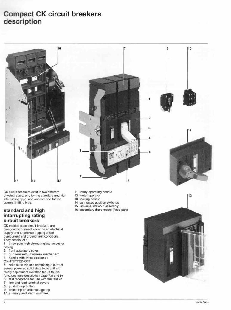
current limiting circuit breakers In order to compallbihz9 SImplicity of ooSl9n and etliclem methods, some of tho principles used to provide a last contact opening are descnbed as follows In senes aSSOClarion oitha baSIC CIrcul i breaker and of a Wmlliog compartment equipped WIth an original system enables outslandir'lg performances 10 be obtained • very high interrupting capabtllty . • sp8C181izallon of lhe devICes according to
o
the currenl lO be inlerrupt8<l the. baSIC CII'C1..ul breaker Interrupts
currents 01 up to 8 • current sensotS rating. over this value both deVICes operate
SImultaneously. This mUflJal assistance notJCeably reduces con tact wear
These performances are obtained by COmbination 01 the follOWing techniques In
the curre nl llmiling block • contact repulslOfl • enhancement allnduced magnetIC l ie~ • • arc quenching.
Arc quenching due 10 !he design and matarialS or the arc chute. a magnetic !oree F draws the arc mto the V-shaped plates. It IS !hen spill and cooled un'~ e)fbncborl.
ContllCt repu lsion EleclrodynamlC lorces are generated by me curreot llow lI'Ig 10 parallel COrlductors The ITIOVIng COfllaCt 1$ bIown-off by the repulSiVe lorces, which appear OIl a shoft ClI'CUII CUfren'
5
Compact CK circuit breakers description
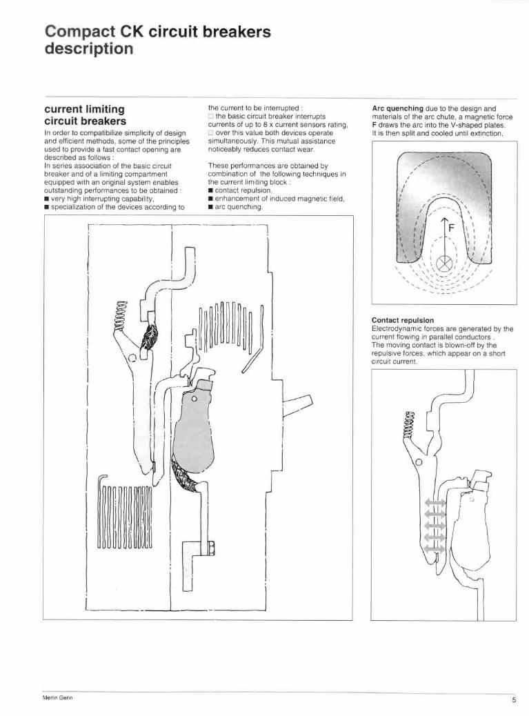
Ip and Ilf: curves Tne limitation capability 01 a CIICUII Dreaker is mal characteristic whereby only a current klss than the prospective faun currenl ls allowed to Ilow under short-circuit conditions This IS Illustrate<! by rimlla1l0n curves whiCh give · • the limited peak lei-through current In rela tion to the RMS sym. value 01 the prospective short-circuit eurrent (the short-circuli current tha t would tlow conlinuausly in Ihe absence 01 protective equipment) ; • Ihe limited let-through energy (Ihermal stress) In relation to tha RMS sym. va lue 01 the prospective shon-clrcult current.
'" ,-__ b llllak
;r-, / \
" \ prospecWo 11:$ I \
I \
t\'~~" \ limited Isc \
\ \
InstallatIOn 01 currenlllmiting CircUit breakers offers several advantages Better protection Current limiting cirCU it breakelS considerably reduce the undesirable etfectS 01 short-circuit currents In an Installation Reduced mechanical effects ElectrodynamIC forces are reduced. thus electrical contaclS are less likely to be detorme(l or broken. Reduced electromagnetic eff&ets Measuring equipment situated near an electrical clfcuil is less atfected_
6
';
! ;
I i • ! i
•
I ! i
•
, , , ~ ,
,
,
D ' 1:0
II + + , ,
,
, ___ ... _(U~ ......... I
•
•

Compact CK circuit breakers trip units
1 rating plug 2 long lime current setting 3 alarm indicator il'\dicales 90 % load with a h~ed light and over 105 G", (the lowe! limit 01 trJpping) with a flashing lighl 4 Instantaneous plCkup 5 leSI receptacle
lime
¢
~umml
rallng plug
InSlanlaneQus
1S=
"
STR 25DP for general application
at 7.2 ~ current setllng ' min 4.2 sec .. max. 5.2 see.
011 long l ime 011 With rating Plug cat. 00. 35300 CK 400 . CK 800 - CK 1200 : 1.5 to 10 limes current setting
CK 1000 : 1.5 to 10 limes current setting with a max 01 a times
lest receptacle fOf overcurrenT les1ln9
lault Indicators i '''''' by trip Indication of the operating handle remote by alarm and overcurrenllrip switch, see page18
7

Compact CK circuit breakers trip units
STR 45SP for select ive and generator applications
1 rating plug 2 long lime current selling 3 alarm Indicator Indicates 90 % load with a bed light and over 105 % (the lower hmlt of rnppmg) with a flashing hght 4 short time pickup 5 shan time del a ~ 6 tono time delay 7 !est receptab1e
Ins'l&nIBMOUS
cu rrent
8
'~;--. -" . -
overcurrent RMS protection ral lng plug breaker
" delay 11 .5>1.(:ur set
at 6 If CUI set
at 72 If Ctlr. set
m" 12 24 .. 96 ma~ _ 15 JO 60 120
m" 0.75 150 3.00 6.0 max. 0.94 1.88 3.75 7.5 min. 0.52 1.1)< 2.08 42 max. 0.65 1.30 2.60 5.2
of! lOng time 011 With rating plug cat. no 35300
short t ime
instantaneous
ptckup 1.5 to 10 If current se«11'19
delay bands 0 . 0,1 - 0.2 . 0.3 CK 400 - CK 800 : o,",erride at 15 times current sensors
CK 1200 override at 12 Umes current sensors
CK 1000 . ovemda at B limes current sensors
lest receptacle lor overcurrent testing
fault Indicators ,~, by Inp indication of lhe operating handle
192
24" 12 15 83 10.'1
remole by alarm and overcurrenllfip switch see page 18
384
<8" 24 JO 16.7
20.8

Compact CK circuit breakers trip units
STR 55UP for all types of applications
1 rating plug 2 Kmg Hmo pICkup 3 alarmlndicalor IndICates 90 % load WIth a fixed Ugh! and over 105 % !the lOwer lim,! altripping) With a !lashing light 4 short time plc1o;up 5 Instantaneous piCkup 6 local faull and load Indicators' they consIst in bUilt-In light omlttmg diodes • laulllndK:alors thaI discriminate Ihe 3 causes 01 tr'lpp<ng overload, shon ClfeUI! an<! ground laultll any • tillrgraph indicating the load In steps 01 60, 70, 80 ~ ollhe CtJrrenl setting 7 groond fault ptCkup 8 gro\lnd faull !tme delay or second load mOOiloring PIckup 9 load mOnilOrong pickup 10 short lime delay 11 long time delay 12 test receptacle
Overcurrent protection
I,mll 1or19 mne
Ground fault protection
,¥ound
current
I ~ th<e lowest ~up 50n1ll9 ot rrn In~e~ broe Blatm Jc2 may nor WOf\( plOpe'1\' ,I !he k:>ng lIme curren! 581\Jr1g ,ndiOl Ihe load decreases belOw eo ... ~ Ihli plug ril ing
plug ralln9 min 1c2 piCkup seUmg , ¥
0.810 1 x correni sonlng
0610 1 ~ cumml seiling
, option T reSidual SCh6rne. OphOll W SQltrce ground relum The m ...... 'mum g,ound raun pickup 'flOOi5 1991 Nat<Oll<ll Eloctncal COOB paragraph 230-95(a) (no! i!xcea(l 1200") • no! aVB~~tlIe With ground !au~ p,OIIl<:IIOO (0Il~Q(I n .'!i see bma-cu"enl curv .. page III
ImfiltH ---"",-, ,
overeurrent RMS
delay " aJ15xCllrsel mm '2 2' " .. m~ " 30 60 '20
al6xcutsel. mm 0.75 I 50 3.00 6.0 ~, 0.94 , .. :1.75 7.5
at 72 x cur set mm. 0.52 ",. 20S " m" 0.65 '30 2.60 5.2 short time PI~~- _,_ 51010 X currenl seiling
dela~ bands 0-0.1-0.2-0.:1 Instantaneous CK 400 - CK 800 2 to IS limes lhe currenl sensors
CK 1200 210 12 limes Ihe curranl sensors CK 1000 210 a times the current sensors
test receptaclft 10f overcurrent and ground laun testmg
ground fault protection (option T) ~
pICkup 0.21006 times Ihe currenl sanSOfs delayoand 0.1 - 0.2 - 0.3 - 04
zone selective Interlocking (option Z)
10f short l ime and ground lautt protection - see page 10
load monlloring (opllOn R)
Inllerse Ume
alarm closing
lime delay ~ opening lime delay ,~
fault and load Indicators nol dlSCnmlnatea local
leI" 0.8 to 1 • cur.ent salting 1c2'<1 ,,0.5 to 1 x current oothng
Irl '" Irl2 (lr" long lime delay) tr2 '" Irl4 !lr". long tome delay) Ii~ed al 10 $&C.
oy triP Indlcallon of Ihe operallng handle
'" 240 12
" " l OA
remOie by alarm and overcurrenltnp SWitch see page 18 discliminateO local
femote With opllon F - see page 11 Wl1h optiOil C (communication)
,.. "'" " "" '" 20.
9

compact CK circuit breakers trip units
neutral sensor location breaker
neutral sensor zone selective interlocking
wiring
18-14 AWG/ I .5mm'
SO loot/t5m twiS!&d or no!
GrOlJOO laull protec1ion may be applied on 30<1 W Of 303W circuits, On 304W an external neutral sensor must be used. This neutral current sensor shall have the same ampere rating as the breaksr.
r----t<l ...... The following are current sensors lor use with CK breakers equipped with STR 55UP trip units with option T.
Wir ing II shall be as indicated in opposite lig. and on the neuual sensor label. Observe control wiring (terminal S1-S2. T l-T2). Terminals • terminals S 1-52 (neutra l sensor) are of "quick-connect' type (1I4 ' lemal8 tab socket are supplied with current sensors), • terminals Tl·T2 (circuit breaker) are pressure type terminal blocks. These terminals are Intended lor use With 1810 14 AWG stranded copper wire
zone selective interlocking (option Z) OpHon Z provides selectivity and redwces the duration of fault compared to traditional time-delayed selectivity. By interconnecting several trip Units. It locates the ground faull or short-.clI'CuII and allows the upstream cirCUit breaker to tnp at the minimum time regardless of the time delay settmg of thiS breaker
Fault 1 CircUit breaker A will clear the fault within the minimum time delay regardless 01 il s time delay seHlng,
Fault 2 Circuit breaker 8 will inform the upstream ci rCUit breaker A thaI it Is clearing the laull and will prevent II from tripping instanta· neously As a safety feature. the tJ.reaker A wltl trip al the end 01 its time delay se tting If the fau lt Is not cleared during this time. Note : • CirCUit breaker terminals are delivered With "in" terminals )umpered Remove the jumber when Interlocking wi th a downstream breaker. • Compact CK type molded case circuit breakers may be also Interlocked With MaSlerpaet dreuit breaker with ZSI option, • do nOI ground.
10
IL-+-______ ~ ...... ~----~_+-+_----
neutral
B
TI
SI
ground lau! ~==S~I f=T~I~~~=~~=!~ leede, neutral cr s - ~ ~ _ ) breaker S2J,. T2 0 ' 0' o~
,
A
I " ~. 711 001
, ~ >-;;;-
max. len h
wiring
no. 01 b,eakers
" 211 oul
I ''';JiO
18·1 4 AWGi15mm' 60 footl2Orn 1wrs19d ~ palffl
008lurn pe' 4' /l0Ctn
uPSlf1lam: 2
downsl'eam' rIO limit
compact CK circuit breakers trip units
load monitoring, fault and load indicators
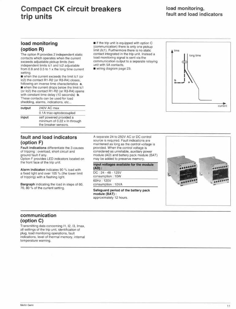
loa-d- m- o-n- i-t-o-'-i-n-g---------.-,- ,,-,-,,-p-o-rn-,-;,- eqUipped with optiOfl C;----;:=============:; (communication) there Is only one piclIup
(option R) limit (let). Furthermore there Is no sialic The option R provides 21ndependent static contact integrated In the trip unit Instead a contacts which operates when the current load mOnitoring SIgnal is sent via the 8)1ceeds adjustable pickup Hmits {two communication oolPUl lO a separate relaYing Independent Hm!ls let and 1c2 adjustable unit wITh 5A con tacts. Irom 0 8 and 0.5 to 1 II the long bme curren! • wlnng diagram page 23. setllng. • when the current exceeds the fimit let (01' 1c2ltho contact At ·R2 (or R3-R4) closes, loIIowIng an IflVOrs6 bme characteristics I . • when the current drops below the limit Ie 1 (ollc2) the COOled Al -R2 (or R3-A4) opens WIth constant lime delay (10 seconds) b. These contacts can be used lor load shedding, alarms. Indications. etc ...
output 2401/ AC mall
o I A triac-optodecoupled
input set! powered pl"ovided a minimum 01 0.22 II in through the breaker sensors.
fault and load indicators (option F) Fault indications diHerentlate the 3 causes 01 tripping . overload, short circuit and UfO<.lnd faun II any. Option F provides LED Indicators tocated on the IrontlaC8 01 the trip unit.
Alarm indicaton indicates 90 % load with a Ii~ed light and over 105 % (the lower limit ol tnppng) with a lIashing light.
Bargraph indicallng the toad in sleps or 50, 70, 80 % 01 the current selling
communication (option C) Transmitting data concerning It . 12. 13. 1IT\8)I., all sailings 01 the trip unit. iden\lficatlOfl 01 plug. load monitonng operations. lault IndicallOfl5, level of thermal memory.lnterl'l3l lemperalure warning.
--
A separate 2<1 to 250V AC Of DC control source Is ~ired. Faull Indications are maintened as long as the control ...a!tage Is provided. When the conl roJ vollage Is considered as unreliable, au .... Wary power llloouill (AD) and baltery pack module (BAT) may be added to preserve memory.
Jnput vott.gn .v ..... for the module (AOJ: OC · 24·48·t2SV consumption : t OW 60Hz 12QV CQnSUmption • l aVA
Saleguard period of the baltery pack module (BAT) : appro .... nnately 12 hours .
,,~
IDog time , I , I --- •
current
-
"

Compact CK circuit breakers trip units
mini test kit Overcune"t protection tesl ptOCeedure 1 operate on ·OFF load· condItIOnS 2 record the. shor1lime Of Instantaneous p.ckup setting anti sel the triP unillo the minimum sening. 3 closelhe CirCUlI breaker 4 connect the two + and • tesI leads Into Inp uM lest receptacle. observinglhe .... - ovefcurren," marklflQS . 5 pte,s the test krt push button, the afcuil breaker WlU trip. 6 return to initial setting
Batteries The mini tesl kil requires live 9 Voll batteries, Alkaline batteries are recommended.
Dimensions : 5 1/2 )(3)( 1 1/2
portable test kit Warning : touching test plug pins may cause electrical shock when power cord II connecled. Power switch shOUld never De In Ihe ON position unle81 lell plug is connecled .
• prior leltlng : 1 operate on 'oft load' conditions. 2 set control voltage selector located al The back oilesllolto proper voltage. 3 switch 101 control power flaS 10 be in the OFF posillOfl. 4 remove the transparenllrip unit cover and connecltestteads eccordmg 10 '+. overcurreot' markmgs. 5 plug In Ihe power cord 6 tum control power switch ON. The 'power on· lamp shookl ~ghl. 1/ not. check The source, then the test kll luse ( tA fuse). 7 close the breaker.
• long time : leSI leads shall be conf18ded according to
' •• overcuflenl· markrngs (on Inp unil). set current selector K of tesliol al trip unil
long time setting (see Iablel). -. move If switch. The breaker Will trip in the following tripping time ; -STR 25DP ; 50 < 1< 70 sec. - STA 45SP . STR 55UP ; .... ..... 15 30 60 120 240 '80
t.bIe 1 : Vlllue of K -CK 400
.. time 5<t<9sec. 10<t <15sec
2O<1<35sec. 50 < 1<70sec. 100<1 < 150 sec. 200 < I < 350 sec.
.... _1·) ...
200 225
mini test kit portable test kit
Every trip unit is equipped with II lest receptacle that can be used With II lesl kit. This particular design allows II safa and SImple 'esung. Tests perrorrned by test k,IS are only functional tests designed to electrically lest the operating inlegnty of the Irip unit, the !lulI: shiller and the mechanical operation 01 the breaker. Tests lire nol designed \0 caJibr .. le the breaker. Calibration can best be done at the factory. , mini lest kit
portable test kit STA adapter
cet. no" 43362
55651
46900
Caullon : when breaker trips release the test switch ImmedlaU)'. Under fW) circumstances. shoukl lhis switch be In Ihe 'ON· positIOn tor more than 120 % 01 the expected maximum tripping time.
• short time or Instantaneous : tesls leads shall be connected according
to ' • • overcurrenl' marklngs (on lrip ul"IIl). move PICkup SWItch lor one second max.
to trip breaker.
• ground fault (reSIdual scheme) : Caullon : lesl leads shall be connected according 10 ' .. . grOund' markings (on trip uniT). Move poekup sw"eIl 101 one second max to tnp the breaker.
trip unIItGnt time .... : 1.00 0.90 0.50 0.55 0.65
0.45 050 0.55
Q.IO
0.40 0.45
1
--

Compact CK circuit breakers time current curves
overcurrent protection STR 25DP trip unit
1
-+- -
~:: ~= ~000 :: CII.2OOIIo CI( ,_ e.ooo !oIl.COO Ct< _ til .00,..:.- '00.000- M:oOO (;1(11(0< CI( IIOOHIi 100000 e.:JOO
cO( ll)O(1OOL '$COOl 15O,00Il
~1~ ' C)('iICO<" _!?O°OO 55,000 CI('~ lao 000 15(1,«1)
- 1-+
I
~-* ~* ""M.* ".""

Compact CK circuit breakers time current curves
overcurrent protection STR 45SP and STR 55UP unit
• •
, ,
•
,
• 1"'''0 "
r r c __ ninR
1, .0 $ """"I,""'CIIoI
t--I~
, r
0.3
H+Ht-II+~, j±j;11;tttl¥o.2~1 ... on II
·'0.1
o
I f
:± - ~ -... .... -= ~~ - 2OO,22!I Z5G )lG ~ <IQQ
~ ~~ - _. -. MQ 70Cl IlOO ~,~ ,- loOO. -. 100. 800. I 000 ~,= ,- IIO!!. 700 Il00. 900. ' OIX), 1200
:=r - ~ ...... .... -...---:;:: ::::: ~ ::::" ~~ ~,~ $.., Co< Il1(1C1N COl .:lQONN M,~ ~,~ $,~
CM <lOOt< COl 00DHI1 ,~ .. ~,~ Q,~
CMI!O:It< 0< _ ' 00.000 ~ .,~
~,- , ... '.- ~,~
~ ,- ~,- ' 00.000 65 ,000 Q~
~,~ ,~.ooo l~.OOO
~ · ~ --t- r f
~t + ,
+ T
H + r
~ ~ Ino __ . :
C~ 400 2 '5' ......... _ C~ IlOO 2 '5 .<1IO'eI"O_ , COl'~ 2
8,,,,,, __ e M \200 2 12 • CUfTWII_
, , (~.od .. ....... on S~ 4~1 ---,--0.3
0.2 ·
0.1 , , , ,
0 -,.
, , . $ • 'U'O • • 00 ~lo(Ie
• "' ... ..,.. .... ~'"'" - - ('") •
, • • • • • • • • •
, , • , • , • , ,
, • • , • • • , ,
, • • , , • • • " •
•

Compact CK circuit breakers time current curves
ground fault protection (for STR 55UP trip unit)
!!SSS8 • , • • , • "I""~ , , • Jll" ,g
,
r- I I ~ f----'-- 1 ·
•
I ~ l 1--+
, , , pIc-"" ,
" 0.6 - Ill . Q~ 01 . ........ _( ... , ~
, t- --t
I , , • " • , • • • I -• 1--+ 1
- T • " .. • • ,
• • • , , ~ T
, 1 , "~ f L
• • • • • , , • -+ .
0,' ~ · ,
~ 0,3 ,
I.: 0,2 .. , ' [ I • • .~, , 0.1 .. , , • • · , • ,
• • t-oo
, .. I -t •• , • , , • , .. ,. • I Z , , • , .. $' • 0
-- _ ..... aI.....- ........ ~ 1t1
- - .... ... .". -~~ - l'OO ,m, m~l6O OIJ)
~- - CI(I, SOXI, IGO 7W. lIDO ~ .- .- 500, lOCI. 100. 100. 1000 ~ , - ilooa 800, 700, 8OD. I(lII, '00(1 1200 - ~ ..... .". ....... -- - -~ - ~- e_ ~,- .-~
_.0.._ M,_
~- .-,
'" ~ C~_ ::.: ::
'" tOOO>l!. CK ,_ ' ;;;.;; •
1 1
-+ 1+
- ,
i ~'
I
-t -
t
t ~
•
t
I
• • • • .. • • • • •
• • • , • , · , ,
,
,
• • • .. • " • • •
15
Compact CK circuit breakers time current curves
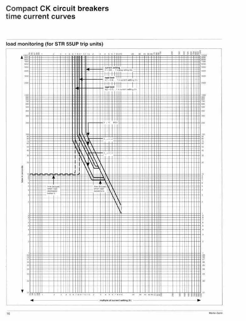
load monitoring (for STR 55UP tr ip units)
:!II!! :;!!! , , , • , .'8." " " , , • , ,
• T •• !.
-,-"
t t - , ~~O.8 ' , pIoIg'*'llllo) ~ ~ , --- ~ 1<" . 0 .1 I , .".,... '"""'e I,,?
1 • I
,oo • • " • • • •
" • • , •
---r-
II
-~ ~
, I -
I I
I ~~ UL __ L! · I
I .. ,~ .~
I ~.' .
~
. + I" ... .. .
. ~\ ~
I'{\ F' I
•
• -- _"""'Y«l, -- t -- , -+-· - -, t _. , -t-, ,
, • , , , • • , , -t
~
+
,
I I I , ,
, 00 '" '"' ~ illil.~
,
~
- ~
,
1
, I +
• • • • • • • + , t - j t- t t
•
' 8 !'! a~15 , , , • ) ., . .,,.,. , , . , • , I , • • , 0 " • ••• eo, s .~o---------------- muH,pIo 01 w<,...,' Mnlnv 111')
16
,
~ ~ ~ ~ UU§= -,
,
,
+
+
1 H t
~
t
Ii
-
-= ---,
, • • • • • • • •
, • • , , • • • ,
, , ,
•
, • ~ " • • • • •
--
Compact CK circuit breakers
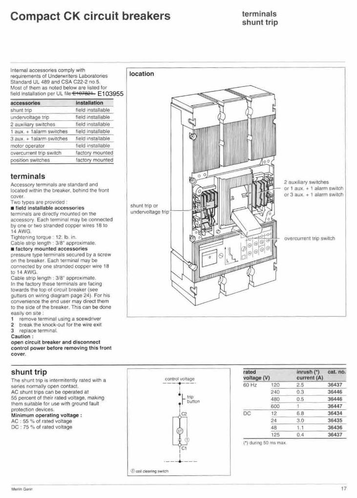
Internal accessories comply with requirements or Underwriters Laboralones location Standard UL 489 and CSA C22·2 no 5 Most ollham as notad below are listed lor !leld InSJallauOl'l per UL 1I1e [ 187821 E1 0 3955
terminals Accessory lemllnals are standard and locate(:! wlth,n the breal!er. behind Ihe tront cover Two types are provloed • Ueld Installable accessorios terminals are directly ffiOIJn:ed on the accessory Eaen 18rmlnal may be connected by one Of two slranded copper WIres 18 to 14AWG Tlghterlll~g torque 12. lb In. Cable Sinp longlh 3.18' approximate • • ractory mounlCKI accessories pressure type lermmals secured by a screw on Ihe breaker Each terminal may be connected by one stranded copper wile 18 to 14 AWG Cable slnp length , 3/8 ' approximate. In Ihe lactory Ihese terminals are lac,ng towards the lop 01 ci rcuit breaker {see guners on Wi fing diagram page 24) For his convenience the end user may direct lhem 10 lhe Side or lhe breakel. TIus can be done easily on Slle 1 remove lermlnal using a sce'Ndnver 2 break the knock-OUl tor the wire el( ll 3 replace terminal, CautIon : open ci rcu it breaker and disconnect conlrol power belore removing this Ironl cover.
shunt trip The shunltnp 1$ rntermltenUy roiled wlln a series normally open contact AC shunllnpS can be operated al 55 percent of thelr rated Voltage. m1'lktng them sui table for use With ground raull protection deviCes. Minim um operating vOllage : AC ; 55" 01 rated vollage DC 75 'l',. ol laled voltage
oomrQI vonage ---...----1 lop
T~ ""~
I c • • . _- -+----
terminals shunt t rip
ro'''' voliageo (V)
60 Hz 120 240
2 aultillary sWitches Of I au. __ , alarm sw'lch 01 3 aUI( ... , alarm SW11ch
overcurrenllnp swllch
inrush (.) eeL no. cun enl (A) ~5
(' ) d\mng 50 mil m:iA
17
Compact CK circuit breakers
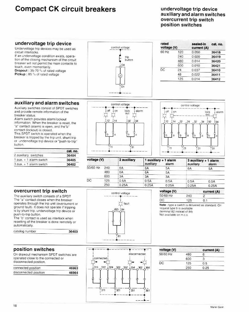
undervoltage trip device Undervollage tr,p devices may be used as
conu~ . olta9!l ---r --· cirCUli inte rlOCkS,
~ It an undeNoltage condiHon eX'SIS, opera- '"' lion 01 the clOSing mecnamsm of the circuit button
breaker will nol permit the maIO con tacts to
00 touch even momentanly. Dropout : 3~· 70 ·.01 fated vottage Pickup : 85 GG of ra ted voltage
,m
-----'- - --
auxiliary and alarm switches conuel "oIta~
AU.l lhary SWItCheS consist 01 SPOT SWItCheS ._- -- , - -t---- ..,- - t ----and prOVide remote IntormatlOn althe loll I on lock I alarm
breaker status. :y:y i':y Alarm sWItch prOVides alarmJlocltoul I" I" I" I .. inlormaholl Whell the breaker 's reset. the "a" contacl (alarm) IS open, and the"b" con1<lcl (lockout) is closed. ThiS SPOT sw,tch is operated when the
I ,
I ,
breaker IS Hipped by the trip un,t. shunt triP or unaervollage tnp devICe or "push·lo·aip· bUllon
II 91
eIIt. no. .-----J ----__ ~---__ ' ... u ~ , I 'ary switchos 36~04
undervoltage trip device auxiliary and alarm switches overcurrent trip switch position switches
, .... _ led-!" cat. no. voltage (V) cunwnt(A) 50 H, '" 0,050 36418
,<0 0,020 36419
"" 0.0 14 364,. 6Q<J 0.0 10 364"
DC 24 0.037 364 10
" 0.022 36411 125 0.014 36412
conuOl IIOItage ~-t--------- --~- -t-
I 0" I 011 lock I alarm
:y :y-----------'i<-~ I" I" Z' ,. '" " I", I ..
, , [ ' [
, [ '
11 PI 131 :91
--~-- -~---~---~-- I I au~ . • 1 alarm SWitch 36405 vollage (VI 2 auxiliary t auxiliary + 1 alarm 3 auxiliary + 1 alarm
3 au~ . ... 1 alarm sw,lch 364"
overcurrent trip switch The au~, r,ary SWitch ConSistS 01 a SPOT The "a" contact closes when the breaker operates through me trip unit (overcuHenl or ground lault ). 11 does !'lOt operato il tr.pping Is by shunl lnp, undervoltage trip device or puSh· to· triP Dutton The b· contact is used as rnterlock when reselling 01 the breaker IS done remotely or automatIcally
catak><;j number 36403
position switches On drawout mechanism SPOT SWitches are operated close to me connected or disconl1ecled posit ion.
cOr"lnecled position 46963 dISConnected posItron 46964
"
auxJ~ 50160 Hz "0 6A SA
480 6A SA 6Q<J 3A 3A
DC ' 25 O,SA O.SA 250 0.25A 0.2SA
COn1rollioltago
I - - T I
:t;!laUI!
1821 184
1 " ____ .1 _____ _
-~----r------t ----f -I I drscoonected t I , ,
~"~~ *- -¢ 13"rtlllll~ -~--~-~-~-1311 ! ~1 1 ~1 i~1
~---- . ---- .---- . I ---.. -
aJann auxlilary .. ~ SA SA SA SA 3A O,SA O.SA O.SA 0.2SA 0.2SA 0.2SA
~ ::ili: . NOle ' lype a SW'ICh ,s dohverad as slandard On requosltyP9 b is ;wailable Itermonal 62 ''' "teM 01 84) Nol ava' iaote on m.e S
volbigeM SOI60 Hz
DC
480 600
'" '50
curntOttAI
6 3 0.5 0.25
M .... "'Go .. "

Compact CK circuit breakers
motor operator The motor opera tor remotely opera tes Ihe ClfCUII breaker BeSides, a togg le remams accessible to open and close the breaker locally ON, TRIPP ED and O FF poSitions <I re clearly Indicated by the operating handle . Pro~lsion lor padlocking IS pfOllided as standard to lock the toggle In the OFF P05ltlon . When locked. manual or remote clOSing IS ,mposslcle Interlock SWitches electrically d isconnect the motor operator when the front transparent cover '5 open lor local opera:,on or padlocking and when me complete mechanism Is roc~ed 10' connectll1g H11emal access ones (shunt tl lp . undervoltage n ip deVice. auxi liary SWitches or motor operator)
Under fau lt conditions the operallng handle Will mdlca te the tr ipped poSition 01 the b reaker. Depending on lhe Wifing. reseUlng carl be done locally. remote ly Of
automat ical ly {soe Wi ring diagrams) Fie ld Installablo.
Note : uSing an ovcrcurrem tII;J SWitch {cat no 36403). automatic resett ing IS nOI possib le alter an ove rcurrenl i e short CIrCUIt o r overl oad. bul poSSible alter a volontary Ifl pplng. local o r remo te
voltage (V) cal. no. SOl60 Hz 120 35678
"0 35679 DC 2< 35670
" 35671 125 35672
I caution canllo! diagram sllall be desJgned 10 Interlock remote on and 011 o,ders 1 ovcrcurrClnt trop SWitch is recommended to lock
remote resetting a1l<), an o lcctnca l 1auil Cl Ilmil sw ilcl1 cv kJc kl "\j SW itch. opens Wilen • Ihe brea~er IS man..all y operated • me breaker IS padlocked - the mOlOf Optlralo r IS rocke<.! CO bUl lt -,n ala rm sw" cn . operates when breaker tops by an e lecT "callau ~ or opening COils CA sell TeemOll sWllch CS elecmcal Inte~oc~ sWlIch de livered WiTh aUlomaHC source Changeover M motor
manual reselling (standard scheme)
1 - 1 - 1 ---
lr""i I :~" I I I I
m""" " Cl co
n MC"lh_h I '" 15' I~~
I
--~- --- --
automatic reselling after tripping
• II 1/
~---- ~
motor operator
overcurrent trip switch 2
auxiliary swi tch
motor operator
rated Inrulh ,," voltage (V) current (A) amps (A)
50/60 Hz '20 6 10 2<0 , 10
DC 24 15 15
" " 10 125 6 10
Operat ing voltage 85- 11 O"·\' 01 rated VOltage Ma • . operat ion f requency 2 per mtnulC Closing time : 400 ITiS Opening t ime 500 ms M inimum operating order 100 ms
remote resetting u sing a resetting push outton
rir-------r--~ 12" I , .tLo't ~L.!_' T' i T' T'
4~J' I
In I'" ,51 TsZ._ ~ I __ J. _________ _
motor operator
overcu rren t trip switch ~
remote resetting during opening sequence
motor operator
overcurrent tri p switch ?
"
Compact CK circuit breakers motor operator
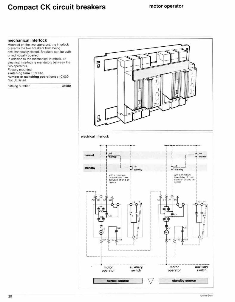
mechanical interlock Mounted on the two operators. the lI1'erloc~ prevems the two breakers trom being simultaneously closed. Breakers can be both or individually opened. In additIOn to the mechanical interlock, an elec tncalmterlock IS mandatory between the two operators Factory mounted switching time : 0.9 sec. number of switch ing operat ions : 10,000. Not UL listed.
catalog number 35680
20
electri cal inter lock
~-I--------~ - ~-~- - ------~-I I I I I 1 I ! I I I
I ,~-. 1 I I r-- -+"" T i l Iii ' i~ I I . I I I I :
standby I I L._.'+on I ' ~'-' I I T SIaI><I>y I T """"" I I I I I I I'Mh 'rI" 'RmUm I I I
:""" """Y <>! ! """ I I I "/".,.,011 on an~ "" I ' , I I "'de" I I I I I I I
";111 a mo,""", m ""","<lIay<>l , _ tl<)rwooo on ~nd 00
'000
I I I I I
:---1 11 I :---1 11 I
I }.11l4A~B2 I, I A264 ~.e2 I, I 12" I '2 l '
i Tt i
f, D~:, "L 1 i 1 _____ J , 1 1 1 _____ , : l.. _________ __ __ : I , , ,
_____ L ___ _____ ___ ___________ L _ _ J , , , , --~---------- ----- -- ~---- --------- --
motor operator
auxi liary switch
motor operator
auxiliary switc h

Compact CK circuit breakers rotary operating handle
rotary operating handle Two verSions are avai lable :
DirecUy mounted This handle 15 dIrectly mountea on the circuit breaker. It accomodates as stanaard up to three paolocks to lock the haMle in the OFF position. However. a knock.out tab can be removed 10 al low Ihe locking of the handle on Ihe ON poSition. Due to the triP free mechanism. padlocking In such a posItion will nol prevent the c ircu il breaker from \lIpping under overcurrenJ conditIOns. The padlocked handle w,ll continue to ,nd,cate ON. Padlock shackle diameter . 1/4 to 5116.
Note : A mechanical Interl ock (cat. no. 44946) links two rotary handles and constitues a manual source changeover. This device 15 only avai lable lor Olrect rotary handles. Simultaneous clos ing 01 the two breakers IS prevented but simultaeous opening IS possible The breakers are normally fixed on a panel or on ralls.
catalog number 46933
Door-mounted type The handle 's removable and carl be filled on a OOQr·mounled mecnan,sm. A 10" long shah extens,on IS supphed and can be cutla a sui table length. A cu!1ong and drol lirlg J'9 's provided The mechanism has the same features as the dlreClly mmmted type ,md prOVides door mtertOCking preventmg the door Irom being opened wherl the breaker is c losed. The handle mechanism can be used m NEMA 3R arid 12 Ilnclosure applicat ions.
Note : Door mterlock can be disabled or defeallld by lurnmg the defeating screw located on the front face. II accomodales as Slandard up to three padlocks to lock the handle In th O FF or ON (by removmg a krlockout) poSition Pad l oc~ i ng Is poSSible only II lhe coupling 01 the extensiOrl shaft and the door mounted mechanism is correct.
directly mounted type door-mou nted type
1 ind>calo< ind,cates b 'ea~er status 2 SCrew removal o~ I I~s SCre .... acti·,ates ,nlcnock pla ia allOwing Ooor ,nterlock
3 onve shall
4 rl1<lunling hardwara 5 back plate prevonts tno door Jrom apcn lng ,n pa dloc~ pos,tron
6 ,nterlock plaia : aha, mmoval 01 screw 121, plato rota les to actwatc doo, ,ntorlock,ng lunct'on
7 male couplo,
8 imerlock deteal allows the oporator to ooleat tile 000, mt",iock and open the door wt,en the breaker is in the ON position (10 be used in eme,goncy only)
Note ; door Interlock can be disabled or defeated by tumlng tne defeating screw located on the front face. It accomodates as standard up to three padlocks 10 lock the handle in the OFF
9 lernale COUlller as""rnbl~
. confleC1s With rna", cooole'
. Insures that the doo, IS closed belo'fl brea~ef
ope'al lon and padlocking - ensures p'oper operal lf1g har><Jle POS l11on
10 co·"e' 11 mountlfl9 M,d"o','are
12 iflter1orJ<. oolear access
13 PO$lUOfI Indlcal'''''s 14 breakable tab proyodes oprfof1at :>il r1locklng 10' ON pos,IIOfl IS ,ubbe, ""skel
position or ON (by removmg a ~nockout) . Padlockmg is possrble only II Ine coupling oj the extension shalt and the door mounted mechanism is correctly done.
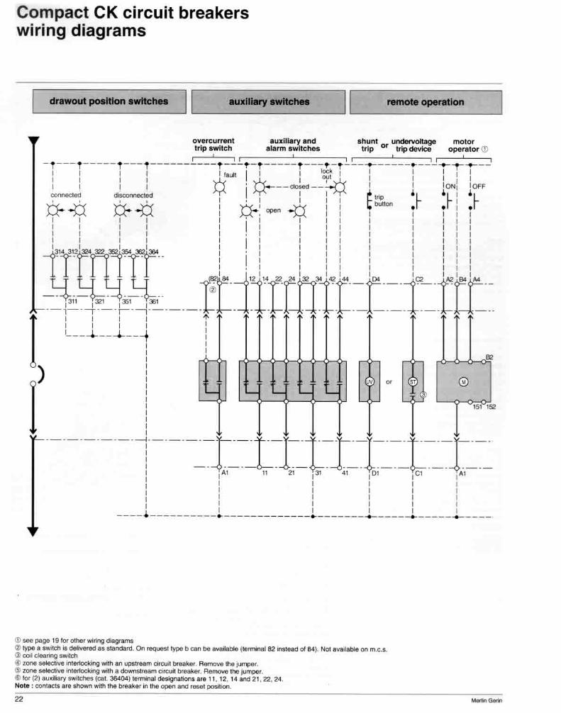
compact CK circuit breakers wiring diagrams
~_d_~ _____ ~_M"_~ __ n_._w_~_-_"_"~ILI _____ owd ___ ~ __ ' _' _W_lbA __ " ____ ~IIL _____ ~ _____ ~ ____ ~ ____ ~!
overcurrent auxiliary and shunt Of undefvolt&ge motor trip switch alarm switches trip trip device operalOf (!I
i ' " I I , i ' I - f--- f-----t---1----------t ---~-t-----t---~-t---~-----~---~~~--
I , I' ',.atl' I Iock r I 11,1 I I I Y-< ~ I ~ I I 't'
I I I I ¥ 'I ~--doHd--1¥ I r IONI 10FF
COI1!\eCI8Ct <iscooolllC1ed I': i r ~ • ~ • r: • r 6-..p 6-..p : 6-: "'"0.p I r"""'" : : . I I I I "I' I I , I I I I I I I I I I I I I I I I
I: I: I 'I: :: 'I I 'I: 'I I I I I I I I I I
131.3121""1""7 I' I I I I I I I I -T- n -T' .. 'I 1 I I I I I I I
~_j' 12i ,. 22 24 132 34 142 "" 1[)4 iQ 1,t,2 :a.J ...
_~;'~~'~i ___ , __ r~ IrmIr-r=l=IIT-' I L __ l __ l __ ~ !
, ' , I I ~~
( I ---- --I------r -- t --l--t-r---l----t---l----
I - - -- -L -- - ,--- ---- --- ----r , AlII 21 , 31 41 ,Dl l eI ,AI : I I I I I I I I I I I
Ii: : I I I I I I I I
.---. ----------. -------------.-------~----~-----.-----
~ ~ ~ ~
®
151 152
\l) 10M Pf!O& ' 9 lor othef wimg dioIglllITIS ~ type • SwrlCtl iI 0tIIvered as slandiIrd. On request type b can be available (18mIIrIaI82 insMNtd 01 e.. ) Not available on m.e ... ~ coil deafIng ,wiech Q) 10l'Il MIeCtiYe in1~ with an upStream 0Iru1 brNlle< Remove Ihe jurTcler. ~ zone ~ ~ wi1h. ~0fcuiI br .. k ... Re!noYe!he jumper. II) lor (2) .uxibry 'wildles (aot. 36404) I&m"ONll c:\es9I'lions are 11. 12. 14 ilrcI 21. 22. 24. Note ; 00fIIaCIS .re .tIOWI'I with !he breaklf in the ooen and _ 1IOM!oo.
22

Compact CK circuit breakers wiring diagrams
L-_________ lrt_p __ U_nl_l _op_I_lo_n_. ________ ~1 1L-______________ "_. _ed __ m_O_U_n_lln_9 ______________ ~
grQund raul1 l Si
'~d monitoring
local laut1 Indlcallons
communications
-_C=:!--C=:!-~T'l " -~--c=:!-1 1
external I I CT I I
,m n'l "r'f"'iS' 1,,,, 1 , i'i , 1 "r' I I upstfltam I I tlreil~"r 'I " l ' 1 1 1 I I I 4 I ! I" I " l~z1'1"' ., ,. =IC-JL-j =-=:=]l~
R """"" option
ute.". 1 n"u!fal senIor [" ",,,n&IT IoT2
zo ne HlecH~" Inte rlckin g ono'" !",mu'a! 121-Z22 CltJk\I.Il~Mtna
ZI1 -Z t2 .. load menltOring
l~mMaI AJ..1O..:
shunt !flp
IC "'''', ~1 C I C:> """",voll ag" "'p te,Ilt",al Dl ·02
I
~ [g 1"'-
:=0 D 1: \: ' -;;
II
possible wi. e ex lls
possible Inle .... atlonal gulters
knock-out& . Break only Ihe!18 required dlpendlng a ltha d n ired directIon 01 wiring
;~ I II
3 au. m.ry . 1 ala'm . w IICII u t. no - 36402 l llu. oH.IItv $ ... ~es 11 12· 14 2' n 24 . 31 32 34 I lW,," S"'""en 91.9294
2 auxlll",,! swhc"". cat. nO - 36404
11 -12· \4 31 ·32..:14 1 aUXlllary _ 1 alarm swUell ca l no· 3&405 ~u>.J;a", ·S· .. ·,ltn 31 32·:).1 MIatm &w tcf1 9 ' 92 ·901
o .ercu" ,"",' Trip swl'c ll 10,,,,,,,,,1 81 8-'
raul! Indlcato/"ll conlfo l power t~""rtIII l F" =12
IOml mo n'Io ri ng I~""'nal AI·R2
"' c ommunl cnllon tJ!rn~n~If' . , .
==-=IJ:.JJ-=:rC=.= ~ L-I _ d,_aWOUlm_ OUnlln_9 --
Z21 1 r122 , A2 1A.4 tl1 1FI2
I ' , II II dowrn;!!~a.., I I 24 10250'"
tI'ea~ef I I AC 01 DC 1 I ---------- --- _ .. -- - - --------- -
.... cO<1dary di.conn&<;Ung bloc ks
0 0
m filiitd --.. ... , .. '" , .. ,., I I 1111 II ,,-
I l i 'i~l~ij m G ~~I 'I .L@ \ " trip unit options
:=> ~~ IZni Z2,1 Fll l ~~ I ~2 I z1 2 Iz 1 2 1 Z22 1 ~~ I
? '

Compact CK circuit breakers
padlock adaptator A padlock adaplator IS available to padlock the circu it breaker III the OFF position. It is sim ilar to the one usea OJ, CE.CF and CJ type, The adaptator accomodates up to 3 padlockS. Padlock shackle diameter : 1/4 to 5/16
ca talog number 44936
Kirk key lock A Kirk lIey lock ,s usea to lock the ClfCUlt breaker In Ihe OFF poSition The deadboll 01 the lock prevents the Clfcuit breaker handle Irom being moved, The key Is removaole wher> Ihe dead bolt IS extended It is prOVided as standard mounted on the righl ·pole poSi tion bu t can be mounted on recuest on the lett pole pOSillon. Mounting screws can be sealed The assembly comprises mount ing plate and screws. II doesn't "'elude Kirk key lock and wire seal , Installable on CK, CEo CF and CJ Irame (not UL listed - not GSA)
catalog number 35636
"
door escutcheon A door escutcheon provides belter appearance of the door cutout
catalog number 44938
~
~ r' "'~
I IDJfuj I
~ l:?' / ,I~
,---", ~
boot The boot pray Ides a light seal wilen a -"aaker is u~ad bec;:~ a panel or door WIth cutou t The square part tlls over the breaker cover and the mIddle prOVIdes <I rubber cover tor the togg le. ImprOVing protection to NEMA 3R.
catalog number 44965
padlock adaptator door escutcheon label holder kirk key lock boot
label holder A label holder can be clipped onto the front cover. 11 permits an easy Circuit breaker Identification.
catalog number 42976

Compact CK circuit breakers main connections
CK Clrcurt breakers may be connected wl1h bus bars or cables on both hne and klad Sides. The type of conne.:: t,ons should De specified when ordenng A held modification IS poSSible \0 e ither mount o r remove the pressure type terminals
front connection
Complete Instructions are given Wllh the set of pressu.e type terminals and In Ihe installation instructions pro~loed wllh the breaker. Caution · modification of termina ls roqUires remoVing of a Irani and back terminal cover. When Ihe modlllcalion is completed, th is cover must be replaced.
with bus bars CK CirCUli broaker may be connected w,'h one 10 three copper or aluminoum DUS bars . 2 .1/4"or 1 314 .1/4"
Term inal cover The shar! terminal cover (1 11/16' M ight) \5 provided. However. the long terminal covel (31/16" height) normal ly supplied with pressure type terminals may be used
Tightening The bus bars shall be secured by TWO boilS.
NOle : lor voltages above 240V, insulation around bus bars may be requi red \0 meel spaC1ngs between phases reqUired by Ine NEe
with cables Copper Of aillm inium caoles may be connected by pressure type conn£!ctors With a capaCi ty 01 :
raling BOO Amp faUng 1200 Amp
• rallng 800 Amp. cat no 46961
I 102 cables 210 10 400 MCM Cu or 1 103 cables 2/0 [0 300 MCM Cu or 1 to 3 cables 410 to 400 MCM AI cable Sirip length : 1 114", • raling 1200 Amp.
cal no 46960 1 104 cables 3fO to 500 MCM Cu 1 ,04 caoles 410 10 500 MCM AI
cal no 46966 I to 3 cables 250 to 600 MCM Cu or AI
Cable Strip lengths: 1 114" (hont holes) and 2 IW (back IlOtes). Cables shall be torqued al 375 Ib.m (318 allen wrench). The connectors arc secured on breaker by screws tightened at 400 lb. In. Caution ; conneClors are plaled for reliable e leclrica l contact. Do nOI abrase Ihem.
rear connection Rear bus bar connections arc used for SWitchboard mountmg. Accordmg to the wa~ of rT,uunling the rear connecllons, t he~ proviae on Nand H t~pe breakcrs vertica t 01 edgeWise COnnecllon poss,bllitles.
edgeWise
J cables 3 cables
flat edgewise
25

Compact CK circuit breakers main connections
universal drawout assembly
When the breaker IS In Ihe connectea poSition, Ihe pflrnary voltage is led through the brea!,;er by means of multiple hnper dlsCOI'Inects A rackIng hanale permanenlly loca ted on tne SlaM·na ry asscmllly IS used to connect and disconnect rile breaker !h,U tile 0001 As a safely fealure In the event 01 dIsconnecting a closed breaker a mechan.callnterlock ""'lIlnp Ihc blca~er before the sepa rallon allhe moun dlscormocts Control \loIlage Is prOVided through secondary disconnects In the connected posItIOn only See page 22 lot thc number 01 secondary disconnects rcqulred UL !lSIOO uncle. hie E 11630S
Ilxed rt
CK 400 - CK BOO -CK 1200 1 CK l000Hl . CK
CK l000Hl . >OOOL
cal no.
46820
46915
mow
19 OlOck ,3~W~'t"~'t==jJ~66~9~Jt ~ wires 36696 10 wires consult us
hed block
7 WlIfI R
26
" "
3 wires 42940 6 wires 4294 1
door interlock ThiS lock preveflls the compartmertt door Irom being opened when the breaker IS In lhe ·connected· poSIhon. II the breaker IS out IntO Ihe -connected· positron With the door open, the lal1e, can tJ.e closed Wltnout disconnecting me breaker.
Note : 101 more salery . IhlS Interlock may be uSed wltn racking Interlock below
catalog number 46834
racking interlock ThiS lock preventS rackmg m the breaker when the door is open. Iinserlion 01 the breaker racking crank IS not poSSible when the comoartmenl door is
",,'ml ca talog number
disconnected position locking
46835
Tho broilkor can De locked In the "disconnectOO" position by the means 01 1 to 3 padk)cks (padlocks not prOVided) or 1 Krrk key lock Factory mounted Mounted on the stationary assembty and I'ICCcsr.lble WIth 111" cubrcl" ClOO' tocked
Note : • keylock IS 01 the caollve key type !ree when locked. • on speCial order. lOCking may be poSSible on d,sconnected an connected positions
padlOCking devr<:e standard
orOVlSlor I="~' OKi:ifk~'"=YCC:Iocc:;:.----=-=O.O"~J~6~ Kuk key lock 35635
standard drawout assembly
UL listed under trle Et t6305
pOSition switches seepaet8
connected POSitron dIsconnected POSitron
door cutout
46963
46964
EscutCheon can De prOVIded to allOW to have access to _ .... handle· tnp unit 4683' rot op handte ... tnp unIt 46832 raCkIng mechanism 46830
~ l[ ~
~~ " " I~I
Ef.5 0 ~r . -~ ? J "'''~ 46832
46830 I
ThiS versiOn prOVides In a smaller vollJme Ihe same disconneClll19 I connecting and safety lealures
11
11
moving block
access to op.

Compact CK switches
when protected by Merlin CK 800N CK 800H CK 1200N CK 1200H CK1000l
suitable for use on a circuit at 240V 65,000 100,000 150,000 (max RMS Sym. Amps) at 480V 50,000 65,000 150,000
. at 600V 35,000 42,000 65,000 ~ .. ",rf<.~~""".~<~'i!1;M?~~~1li~·h"- -'~~d l!r,~i}.l't'J!~&4~~~#.c@~~~~h"~ilj~,~f~,.tii_ maximum rating 1200A 1200A 1200A suitable for use on a circuit at 240V 65,000 100,000 150,000 (max RMS Sym. Amps) at 480V 50,000 65,000 150,000 -
at 600V 35,000 42,000 65,000
i,.tl.. F' ,'/'" '" ~ -accessories /EI()3 95::'-
construction The following accessories of the CK circuit breaker may bEl used with the CK molded
CK molded case switches are designed case switch. identically to CK molded case circuit ~¥.-=-~~~ "w~ breakers, except that they are not equipped ~~ _ _ 9.@
with Yip unit and se~sors . _ . ' . A I. '/1- shunt trip . . 17 U L hsted under Ul ftle-E+eT822: ~ ~. '.5 ~: ~ <-. undervoltage tnp deVices 18 e ] o3'1'it + f\l" -f!d,,,-«.· j<; ) ;:{ . 2 auxiliary switches 18 Caution: u L r , k .~ '"' 1 auxiliary + alarm switch 18 molded case switches do not provide 3 aux. switches + 1 alarm switch 18 overcurrent protection. position switches 18 Molded case switches can be protected by a motor operator 19 CK circuit breaker. rotary operating handle 21
(j) ratings apply for both standard and 100% rated breakers
padlock adaptor 24 door escutcheon 24 label holder 24
dimensions - installation -connections Molded case switch dimensions, installation and connections are identical to those of the corresponding circuit breaker. See page 28 to 35.
,----------_.-- -----~---,
Merlin Gerin 27

Compact CK circuit breakers dimensions inch/mm
with bus bar terminals or pressure terminals 800A ...
CK400· CK800 · C K1200 f ixed mouti ng. front or rear connect ion
with pressure terminals 1200A
l"r - 1.37
"
.... ~~ '" 3.71
"
. " .c.ewl
J (4f mounting 1- 1101 ..
W··'" ':-_l.~
<Jl>- . .
®~
5' '-f ';;:"-:: R I_~f!.o
,.. r ~ -L'·" r 1...._ 52,5 "'. ,>-0 FF
RES ET
1 . -I'--.. -~ ._ ....
I -j t
L •. 33 __ • . 10 • . 52
l - 4.80 115 -
'1.11 In ----- In -
" ,. " , , ,
-<
I 15.14
'" ' _0 • " , , T
'-' , , , I
----'
CK 1200-100% rated only with edgewise rear connections , .. In opllon on CK ~ and CK 800)
with bus bar terminals Cutting and drill ing l or attachemen! to panel .-
= = = V
~ 1,11-' ::t 1.71 1 ',~7. 1.71 ... " " with CK 1200-100% rated edgewise
rear connect ions (u In optlon Oft CK 400 and CK eoo)
= ==
from connKlion
."-4-1 .11 -4-. 111 5 200 5
Door cutout @- ""ndle
r-------1
roar connection
681 53 r-- 'r'73- tr i3.5
• , 2.11
" 1 I • •
0 .31 , 1
I
'" I
L I 1 1
":( ~---
f-1 .26 ___
'"
r-------.
... I~
Ional cutout --~- ~~ -'''' -. .., '"
, , !l3g~
.• L
, 2 .11
-f
, t +-.+ 2:n--- --- -j---+ + 1 , 1 1
•• ..-d ,Ol'" <ircu~ lK_ ... ell 12OON_ CK 121,Qi ....-",,,, r.I"IlIIA>.I"" l20CA ."' ......... 10< ..... ., . '"""""'" 0b!It opar;. '" 1<51 ~ W21 ~ 013 ""ChC$ ( l JOO by S50 by ~ """ '
""" I """""""" "f"""""" of ro 5QUo\l1 "",,," ;~ ~ 00\!l.' lOP oncI _ • '00'.,.,,,, c.cu~ b' ... ~ .... (..,.po NN 01' ItH I r.wl_""~ope-~ .. , t'Opttoer'll'" ,a<-"" """, _~"" ,,"_ -_. CK~ C!(/IOO ...o..,W2,,,,,()g_ < lo:!O "" ~""ZlO"""1 ---'-0(Il00 ... '""'l_90-C ..... _ .. I'!iC'MlOcor<:U:'<nl C~ '2UO ~''''''lQt..,O . l ...... 1I3JOC!'r.!(Ibyl!iO''''''h. __ _
"
, , 1 bl 1 r , t l .. --
, " _.
4 .~51 Ibl l , 1 '" , .. , , ,
-i t ... I L _____ J

Compact CK circuit breakers dimensions
CK400 - CK800 - CK1200 drawout mouting (universal drawout assembly)
inchlmm
2.75 2.75 l .OJ ~ 70 "' ro - 77
ITIOIJnling on a pane l
hole. mounting
opllonal s lHve lor operating Ihru door
-. 13 .39 3<0
1B.16
""
~~~~~~~~~~~~~ ,,;0;:" /I base plata 00 . . I I ." . ,
'.5
• 100'10 rated circuit br .. k."ICK 400 · CIC 800) ill. SUItable 101 contU'"lUOUS OP8'8tlOl'1 al 100 per cenl 01 .atlng only il usec in 8 rnmomum cubot:ff! ~ 01 H40by W2 1 ~ D9inches (1030 by 550 bV 230"'"'"1 ''''1I'l001 ve"I,lel,Ot1, CI< 800NN . CI< 800HH Wlnng wl,n 90 C WI'eS based 0t1 75 C 'aled eond uctOf'S ,
2;,~ ., .:.._~;_,_3.69 -i_ 2.99 "" ,-_ , .37 94 76
238
.~
2.55
" Cutling and drilling for attachement on base plllie
13.36
'" j 3.34
. -f 12.7113.69 2.99 i
- 69 · 94 · 76 .....
to IUInal , .60 " , " 66
, \ . , , .. , ,
" 2.05
'" I , ·W ~
, '--i -i--, , ,
." , 222
, , •
~J .. ) .5
,
lesl
, , , , .. +
., , o "
--- ----
~ . I ! 0-~ ' , 'J :
plional cutOUI Or secondory isconnecting locks
1--'""--1 '" ~_ 8.1 1 _ .. 206
Door cutout with optional sleeve and door escutcheon .39
-tj 2s11 6~ .20 dla
6 :: 5 " !1~-----!--rI
.00 , b,.,ker .et. t:-+j ba ll s .67 .
" .22 -+-_ 9.84 5.5 250 ." 5.5
29

Compact CK circuit breakers dimensions
CK400 - CK800 - CK1200 drawout mounting (standard drawout assembly)
inchlmm
.... 25<>
1-3.25 82.'
,." "
2.75
"
I1.SO _ ____ ~ 292
00 , ,
2.17 2.15 2.75 55 "'" 70 --- 70 --
• 100" .. f.ted elre",;1 bre.kerl (C K 400 · CI( 800) are SU,Iat)le 10< COflbnuous operanQ" a1 lOOper eOnl 01 ralong only ,I used in a m"' ........ m cubicle spae(! 01 H40 tty W21 by D9 ,nches (1030 by 550 Dy 230 mm) WllllOul venlJlaD<>n CK SOONN · C K BOOHH Wlnng WIth 90 C Wiles bas.e(l on 75 C raled COOductors
30
(4 ) noln lot mounting on. panel
disconnecting position
,.,,- - - -r-202 1.65
" '" 5.23
l ." "
.63
"
U.
" .63
" ... Il--:d...t.:.Li'~
I
I 13.39 " 0
16.3. 41 5
~~!I:- - ';~' I I __ I,...l I 1-__ 1.28 .J .31 I- 9.33 185 I 9.S 3~5
"'--12.56 _ _ 9.12
'" - 65 -
Cutting and dritling fo r attachement 10 panel
2.60
"
0 .79 2;4
I
" ~O , " " .26 II
"' ., (4 hoIos/
Door cutout with optional sleeve and door escutcheon
1
. 3.65 r 93,5 . , .1 ~_ . ,
:: 105 - 23
i i iI ' ; ,
T , , -, , , , , , , , ,
&! -"- 121 ' , ,
, "-, ,
t I 7 .3~ _ - - 186
I----8.11 ~_
.'7 -. 3.46. .87 22 88 . 7 22 ,
.24 _ 4.12 L.t-.~ 6 120 - 24
,.. , -1 •• " o " 3 . ..
00 , ,., 82. I • , optional cutout 10' secondary III, connecling blocks
1.24
'"

Compact CK circuit breakers dimensions inch/mm
with bus bar terminals or pressure terminals 800A
_ _ 4.53 _ -;
CK1000HL - CK1000L fixed mounting front or rear connection
with pressure terminals 1200A
, 115 I
" 1.31
" .-
(4) mounting ~ hol ..
~_"Dt __ -__ -
,
13.31
'"
." " ,
with bus bar terminals
n = = om II.IIIl:
1-.77J 1. 77 J "
=
1.77
V
1
MOO ser ......
.. , , "
with rear connections
=
.10 .31 2~ 915 _.
I .37 --4,98~ •. , " McrlIn Gee.,
n =
F ~1 . ~3~
=
~ ..... dl.
0 ..
@ - -+-----
0," ® - ~
1 5, r---".~ I • AJI~f~.P_
\ I S O 20" \ -
OFF
RESET I
-5.90 _
'"
15.74 '00
I •. " ""
with rear connections
Cutting and drilling tor attachement to panel 1'01'11 conne<:tion r •• r connection
:[
2.75,2.75,,2 .75 70 , 70 , 70 -
- -- -, , , , , , , , I , } ,
, 3 .34
" I 9 .44
T 2.95
'~
" , 1.87 .19 "'" ~, Door cutout ® twtndle
r r ------~ I , + I , 1-, I r--
/ ' \L
-l- ' t- . I 2.'1-' -
bl
--
, " --
4.~9 , I '" -- ,
-1 I 2.48
r "
6 81 53
, r'in-r i3.5
, 2 .87 '" ~ ,~
10 ... 1 cutout second ......
aconnKllng
.21 d
"'
--
" ! , • • , , .' I O. l l ,
.I
'" ,
L , I , , , , .,
"-'1 ---
r--1.28 _
'"
-. , ""''' -,, .., "". , , , ~,g J~
2-,~7 ,
@ handle and nlmeplale
r- - - - - - --, , , - it---' + I ,
ibli -(4. J L ______ i
--------------31

Compact CK circuit breakers dimensions
CK1000HL· CK1000L drawout mounting (universel drawout assembly)
inchlmm
2.75 3.03 ~ "
"'''"""---I''''l "" 1_ m 1.69 t'" ." " - " - - -
) holes mount ing
on II panel d lsconnec pos ition
ling u rD= --. , f ' ,. .- -,
-, ~ --l--'~J
6.20 15 75
.32 d la
1.53 -':::'::=:'j~c::~=:=t~1.53 39 39 _ __ '~2
Wlle" e'lu~ped 'N,tl! ratmg plug In = lOOOA lise a m,n,mum r;o.rblcie space 01 H5 t bV W21 by D13 '''eMS (1 300 o~ 550 by 350 mm) With a mlIlImum venillali"" c t fill squa re Inches (4 dm') bo lh a t lop an d bottom.
32
optional 51 lor ope,.t; Ih,u door
, , , , ,
''-. 2::1 ./
M,. 0, - ..
.. : (~ ~ '." -:.J ____ :~
Rl1 00 I
- - I I I -
--
13.]9 ",
rJ';" 18.1 • , " " . .63
I " " 2~ ~1.71 ~ " --r-r 3.35
." '\' " 2.36 -t-- 3.69 --t- 2.99 ---t--3.8
j5 __
60 94 16 98 12.91 . 2.55 t....
"' 0.' Cutting and drilling for attacheme on base pla te to pa , .SO
-' 1.30
5 '~J~ I · 91 33 -r 140 , "
13.36 ", 1
~-,-\. , 'I
2.111 3.69 ~2.99 1 3.85 69 - 94 " 76 " 98 1'-
Door cutout with optional sleeve and door escutcheon
~ r ,
'\ .. " " 2.05
" f +-1 H- l.:f .,. " , ,
I 1 , 10 " " , .26 d
"' (' "'" .,)
,
\I'
-, +
-------
f-~ 7i~-.. ,--8.1.1 _
, .. , , , " :-I'
i"-!,-- , optional cutout Of secondary
d isconnec ti ng blocks
,
_ 1-i-2.17
" 6x.20 die ' 0 5
9.25 reI. 2 I .35 4.35
! - ~~';~~~~::-t-~j',~~::~~'~"t_':J;- t'in « 24.5
breaker I re t. 1:-+1 I' basis .67 .
.22 . 5.5
9.84 r7 ,~ --
. .22
"

compact CK circuit breakers dimensions
CK1000HL - CK1000L drawout mounting (standard drawaut assemblv)
Inchlmm
,." ""
2.75 2.15 3.68 , - ;0 ... 70 ' - 9351 d::lfficp
1- - t "+-''-Ir~rb'"
d::l 3.25 "'.,
,."
I 4.13 3.68 - - 105 ----- 935 I 11 .50 ___ _ _ ,..,
'"
"'~V !+Ei-' _2,11 ~2.75 _~_ 2.75 _:.-S5 70 70
"/hen equipped ",lin .ahng plug In ~ 1000,1. use a m,rumum c;ub,ef(l SIlace 01 H51 by W'l 1 by 013 lneh"s (1300 by 550 b)' 350 tTlmj Wlth a ,rummum vemilallorl 01 60 $Quare inches (4 <1m') bOln 31 lOp a nd ballom
(4) holes 10. mounting on. panel
d'lconneel l"g pol ilio n
11 .48
'"
L _____ l0.8J
.. 12.81 275
5.23
'" -
=~~-~""~=::' _ ___ 13.26 2 .58 337 65
" "
."
1 13.39
'" 16 .34
'"
95 3.35 . "
Cutting and drilling for attachemenl 10 pane l
,~
"
I 0.79
'" I
-'--1- 3 .65
4 13 --i 9, 93.5 + ;05 r "23 -i. r i
,
i I I
, , ~.~ , , , , , ,
&! , ,
\ , , , , , ,
, ,
.
,.. , " i -. ., , , " ,. " 00 , ,., " , , ~
,~ ~ J "
r 01'1101'181 cutout lor lecond .. y d iscon necting b locks d • . 26
0 6 j 4 1lo.'6s}
Door cutout wilh optional sleeve and door escutcheon
, 1--''':] '" _ _ 8.11
.17 -.-. 3.46 _ .11 22
1, 88
122
" r ~j -- · - f.l -: " 19 : I ' '!: 6
I --{. .~.. . :-- .~ 5.784.29 n: 5.39 147 109 ~ I /37
L r::::ilfulF!fri)J.\--l
,15 dl. N
: I : . ,
33

Compact CK circuit breakers dimensions inch/mm
door escutcheon fixed mounting
door escutcheon door interlock external neutral sensor
drawout mounting with operating handle with rotary operating
handle drilling of the door
door interlock
, I
+
." w r , " '" j
3.56 , OO':_l -1---- -r. . r , eaker " .. ."
" "
I
_. ~I -t- 2s17
-<-
i I
ref. 2 I ., "t '
! V ' I
ref. ,~ .67_-r L
• • . 20 dia , @,
-
_~',' r ~;i', w
" -r -=r " , 24,5 .96
24.5
9.84 17 1-.. 2 - - -""
reI. 1 : whell mou"Hng on a tulse plale
external neutral sensor
" " . 3~ ._ w
1--
." I 95 ,
-
1.77 1- 45 --, "r
$ -$
(4) h ales ", ...
~o
I ~
." " , 1--3~4 _ _
'" ,-',,,-!, : j,,,
32 1-.31
•
4.92
'"

Compact CK circuit breakers dimensions Inchlmm
motor operator with mechanical inl~rl ock
motor operator rotary operating handle
1.18 ,...--- ' ,;~,,~ ---I" >"~2~ -Ie" l'
.. " '"
15.15
13.78
'"
-++-_____ 24.60 ______ _ r - 625
25.78 ______ ~
'"
n J
L IIH :U5/ l :12.15 ~.235 325
IIH :9.72 ll :1J.26 _ _ ,.- 241 337 -
--.!!H :10.39It : 13.II!_ 264 354 -
rotary operating handle
direc tly mounted
door c utout d irectly mo unted !Iud mo untin g
r---- -, , I , , I I
, I I L ____ ...J
6.83
lI ush I surlace I d irectly mounl!!<l
, , , J -- ---
- I-, - - f-- - 1-- I-- -
-- - 'L -A (' J
." 6n , (' J add 3.54 / 90 1& cu"emllmmng block
door mounted li ~ed mounting
(3) holes .22 d la-, r -----,
'" , I I ,
1,37 I I 351- . i
f -\=' ~ -+-., H ' ''~'I 11 ~; ~~5 "I t
270 . 1 li -(OJ 68 'TT !'::-:':-JT!f'-'~j),
1.02 1 6.83 _ .25dla 1 D6 2fj I 173,5 t '.85 lor Ilush • I • 4 7 mounting only
door mo unlC'd d,awout mounllng on base plate
""MaCe . ~
mountin g . ~,
' lush B ~" mounting B ~,
I I Il ush mounted
C! 5u rtace mounted Ci d irecTly mounTed
H,H
10.82 1215 20 .66 1525 12.40 / 315 22 .24 / 565
(~ breaker mounting hole
m.' 14.371365 24.21/615
15.94 /405 25.78 1655
(5 drawout assembly mounUng hole
Note: sha lt carl be cut 10 req u"ed length
doo, mo unted drawout mounting to pane!
35

Compact CK circuit breakers appendix
standard tests For solid state trip breaker, and uncornpensateCl thermal breaker rated 40 C, the test sequences are
lost
200% calibration at 2S' C In -F) 135% calibration at 2S' C (7T f )
calibration of adjust instant trip
ovcrload
tungsten lamp load
100% calibrat ion al 40 C (104 F)
temperature and 100°'0 cal ibrat ion at 25 C in F)
endurance
200% Cil libratlon at 25"C (77 F) repeated
135% calibration at 25 C (77-F) repealed
mterrupling ability (Y sequence)
Inlerruptmg ability (Z sequence)
200% trip oul at 25°G In-F) dielectriC voltage withstand
UL 489 test procedures (abstract from UL 489 w it h revisions through Apri l 6th. 1987)
......... =-=- -. X Y l
• • • • • • • " ~
• • • • • • • • • • • 1 Awlioe. ~!'\Iv I", o,e.~e, .. a"'<l5 S A Of Ie .. , 125 ()f '251<5(lV c r _
standard specifications 200% cal ibration at 25 C The breaker must trip Within time limits which depend on the rating from 3 m inul e~
fo r a 30A rated breaker, up to 30 minutes over 2000A.
135% calibralion at 25 C The breaker must triP Within Iwo hours (for b reakers ral(!d more Ihan 50 A)
Calibrat ion o f adjustable instantaneous tr ip The b reaker must triP w'thln the range of 80- 1 2 (.o~:, of Ihe maximum marked tripping current and 75-12S,}o of the mmimum marked tripping currerlt
Overload • up 10 t 600A f ifty operalions at 600% of rated currenl • 2000 and 2500A twen ty·Iove operations at 600 % of rated CUfrent • 3000 to 6000A : three opera t,ons at 600~G fo llowed by twenTy-five operaflons at 200 % of rated curren! The power lac tol shall be from 0.45 10 0.50 lagging
~ Ao!>l e. Only lor tho",",1 break. ", ,. !ed 40 -C
Temperature When connec ted wuh specified cables or bus bars (see below) and with ,Is rated current. the temperature rises on the breaker and at I\S terminals does not exceed speCified limits
Fx~mr>[A<; nf <;r>oc ififH1 w"p.~ ~n rl h",,, · • "75 -C' copper wife
ratIng number
100A
" 250A
'OOA 2 600A 2
800A 3 1000A 3 1200A , • copper bus bar
rating number
1600A 2
300DA
112()OA O'9S< 1000)\ ' ",' +
.ID 1 AWG (60"C)
3AWG
250 MCM
3/0 AWG
350 MCM
300 MCM
400 MCM
350 MCM
""" 1/4 x 3
. 2 114 x 4
Endurance The breaker must complete an endurance test : • operations al rated curren! and rated vo ltage • followed by no load operation. The power facto r shall be 0.75 10 0.80 ["'Jain'J
Examples ' .. - number of eyc," of ... .....-.,., without inial current current
100A 6.000 ' .000 10,000
225A 4.000 ' .000 8,000
'OOA 1,000 5.000 6,000
600A 1,000 5.000 6,000
800A 500 3.000 3,500
1200A 500 2.000 2,500
1600A 500 2.000 2,500
2000A 500 2.000 2,500
2500A 500 2.000 2,500
3000A '00 1,100 t ,500

compact CK circuit breakers appendix
Interrupting ability (V sequence) Aller endurance leSts and calibrations repealed. Ihe breaker completes an opening lollowed by a close-open operal/On (O·,-CO). with speclliea current
Examples tor three pole breakers .
frame rating AMS Sym. AmJ-(.3-pM o-t-CO)
looA 3.000 225A 3.000 , 00A 5.000 600A • . 000 600A 10.000 1200A 14,000
1600A 20,000
2000A 25,000
3000A 35,000
I 4t>cMI ~50V
Interrupting abilily (2 sequence) A 3·pole breaker rated 240. 480 or 600V have to complete an opening operation and a close·open operat ion (O+CO) on each pole, a\ rated VOltage. !allowed by an opening operation (0) USing alilhe three poles for the frame sizes up to 1200A. an add Iional close-open opera1oon on the three
lXI'''''' IS ' t!<.IU""o.J)
Examples for three pole breaker :
1{)() 10 SOOA
3000A
RNS Sym. Amp!
O-t-OO 0 10.000
O-l-CO
Dielectric Aller lests. Ihe breaker must withsland tor one minu!e a voltage ollOOOV piuS I .... ice the rated voltage between • line and load terminals • terminals of opposite polarity • live parts and \I'Ie overall enclosure
Optional tests : • high avai lable lault current Breakers havmg passed ailihe standard tests may have the UL label applied at higher values than Ihe standard. Test sequence IS as tallow .
200 0" callbrallon mtermphng capacity . an opening
operation loliowed by a close open operation (O+CO) on all poles are performed on the circu it breaker. The power lactor over 20000A shall be 0. 15 to 0.2 laggmg
triP out at 250". die lectrIC at twICe the rated lest voltage.
• 100% rated Breakers haVing passed all the standard lests may have the Ul label applied to use the cirCUit breaker In an enclosure. when carrytn-g 100% 01 ItS maximum rating. The cllcuil breaker is submitted to additional temperature tests perlormed as In Slandard tesls. eKceptlhal the breaker IS Installed In an enclosure. The dimenSions and POSSible ventilatIOns shall be recorded and shall be marked on the breaker
UL 489 test procedures (abstract from UL 489 with revisions throu9h April 6th, 1987)
tests on accessories Shunt trip and undervollage tr ip These deVICes ale submitted to temperature. overvoilage, ope,atlOn, endurance and dielectnc lests • overvollage tesl It checkS tnal the deVICe IS capable 01 Withstanding 11 0° .. 01 Its rated voltage conlmuously Wllhout inlury (this lest does not apply 10 a shunllnp wllh an "a" conlaCI connected m series)
• operatIOn The shunt tr ip muSI operate al 75 ..... ollIS faled vOllage (eKcept Ihat shuntlnp deVICes 101" use with ground taull protection snail operate at 55°.) The undervoltaga trip must trip lhe breaker when the voltage IS between 35
and 70% of Its ramd voltage ana snai l seal (I.e. the breaker cannol be turned on ON poSItion) when Ihe voltage is at 85"e or more 01 lIS rated vollage • endurance The device must be capable 01 perlormlng successfully for to" ~ of me number o ' · ..... ,th current" operations of the breaker.
AUllitlary and alarm switches Auxiliary and alarm SWitches must be subm,t1ed to temperature, overload, endurancc ond dlclectnc IOSl3 • overload tesf The lest cel\$lsts of fitty operatiOns making and oreaklng t~ 01 rated current at raled vOllag!!, Wit" a 75-80% power factor In AC and non InuduCllv8 load 10 DC. • endurance The swncn must make and break rts raled currenl at rated vollage, With a 75.80°" power faCIO' In AC. ana non inductive load In DC lor 100°" 01 the numoer 01 operations "w,th current fer aUXiliary SWitches. and 100~ ol lhls numbeltor alarm SWitcheS.
Mater operator The motor operator shall pen arm the number 01 "WI!hout current" operatlorlS Indicated for the breaker endurance tests The first 25 operations shall be conducted at 85% of the motor operator vol1age 'allng The breaker IS 10 be tllpped Qunng Ihese lesls. The nelll 25 operations sna I be condUCled at 110"", ef!he mOtor operator voltage rallng The balance Shall be complet!!d al rated vo ltage withoutirippmg the breaker.
37

Compact CK circuit breakers appendix
recommended inspection intervals Marl.n Gann CUClJlt breakers are designed 10 be malntenance-Irne. However all equipment With movmg parts requites periodiC InspoctlOf) 10 tlrlSI.IIB optimum perlormance and reliability We recommend thallhe Circuit breakers be rOut inely Inspected SI ~ months aller mstallahon, !ollowed by annual Inspection Intervals can vary depending on your particular B:o:peliBnoo
inspection of terminals • conneChons to ClfCUl1 breaker terminals could be Inspected II there IS diSCOlora tion due 10 overtleahng, lhe joml should be (lIssassembled and the surface cleaned before rBIr\Staliahon II is essenliallhal elecllocal connecllOns be made carefully In
order 10 prevent overheallng. • CneCk for terrrnnalt,gh tness
cleaning Remove me dust and Dirt thai have 3CClJmuiaied on the CirCUit breaker sunace and termll1als
mechanical checks Even over long periods CIrcUit breakers are not otten required to operate on overfoad or shOl1-c>rcuit conditions. Therelore illS essent ial to operate 111e breaker periodical ly To tnp !he breaker pUSh the pUSh-to-top butron
38
insulation resistance tests When breakers are subjected to severe operating conditionS, Insulallon resistance test should be penormed as IndICated In NEMA standard publication no AB2· 1980. An Insula tion resistance test IS used to detc lmlne the quality 01 the insulation between phases and phase to ground. The resistance test IS made wllh a DC voltage higher than Ihe rated voltage. 10 determine the actual resistance 01 Ihe Insulation The mosl common metnod employs a -megger" type Instrument A I OOOV InStrument wll! proYlde a more reliable lest because II is capable 01 detecting Iracklng on Insulated sunaces. ReSistance va lues below 1 megohm are unsafe and shOuld be investi· gated. An insulation tesl should be made • between hne and load terminals of Individual poles with Ihe CIrCUI! breaker comacts open. • berNecn ad,acent poles and trom poles to Ihe metallic supporting structure WIth Ihe CIrcUit breaker contacts ClOSed The laller leSl may be done With the CirCUli breaker In place alter the line and load conductors have been removed. or Wllh Ihe clfcllli b'eaKer bOited to a metallic base wnicn Slmulates the In-sclVlce mounting.
electrical tests These tests tequlle equipment lor conducting pole resistance. o~e rcu rfenl and instantaneous tripP,ng. in accordance wnn NEMA standard publica tion no AS 2 They are not wlthm the scope of normal liold operat'on
routine and maintenance guidelines
Important Art tests must be made on ci rcu it b reakers which have been de-energl2!ed, and disconnected so as to prevent accidental contact w ith live part s.
Caut ion Since molded case c ircuit breakers contain factory-sealed and calibrated elements, it is essenlla l that the seal be nOI brOken and the ci rcu it breaker be not tampered with . Molded-case ci rcuit breakers Should not be f ield adjusted or repaircd. In the case 01 malfunctlon, the ci rcu it breaker should be replaced or repaired at the Merlin Gerin factory , or by an aulhori2!od representative.

Compact CK circuit breakers appendix
molded case circuit breaker In addillon to Ul an<:! CSA standards standard CK breakers comply with lEe 947·2 Slant'lard as per tab!e below
CK type J-pole
ampere r&t lng (A)
"
shunt trip r. ted lIolt.ge (V ) UL 489 IISled lEG 947·2 6OH, 120 5O/60Hl 110-127
"0 220-240
480 380·4 15 DC " DC " 48 48
125 ' 25
undervoltage trip device
UL 4691!sted lEG 947-2
DC <"t== DC " ~6 48 125 125
Interrupt ing rating UL 469 - CSA C22-2
motor
lEe 947-2
auxiliary switches, alarm switch, overcurrent trip switch, position switches lEG 947·2 charaClenstlCS are the S<lme as those IMlcated In page 18.
;, flUIIIgS apply tor DOlI! $Ian<lilr(l and 100". rated Dreal<ers
Me~"Gotm
circuit breakers for compliance with other world standards. Where compliance with IEC standardS IS reqUired, Merlin Germ offers a versatile range (not Ul hSled) of CK cirCUlI breakers to meel your speci ffc need Units mcludo three or lour poles vol tages up to 660V, three levels ot Interrupting capabilities up to 660V An extenSIVe range 01 accessones complements the prodUCIline. For luntler ,ntormatlon, please contact your Merlin Gerin representative
39

ACOO3712E
~"\aroOO"" ~Iom and .,. .... ...... ""'" In:wn 1 .... 10 !me. lIwIys ..... "" oonIltmibOn <JI N """"""_ D/v«I 11> _ pUtIicaIion
~. _0.0 .... B Maunce \ItSog.n by ""'EG. V ~ I"" . !Will - prime<I 11)1 In


![811 GUIDE Pump Interchangeability[1]](https://static.fdocuments.in/doc/165x107/55cf967f550346d0338bdb26/811-guide-pump-interchangeability1.jpg)