Compact Antenna for Medical Wireless Communications Applications - Vishay.pdf · ·...
17
Compact Antenna for Medical Wireless Communications Applications Vishay Intertechnology Patrick Gormally Applications Engineer & Product Manager Medical Business Pat. [email protected] 860-614-6115 Topics Outline Basics Antenna & needs Antenna Frequency ranges and types antennas Compact ceramic antenna introduction Overview of wireless frequency bands Short range Long range Vishay Compact Ceramic antenna Suited for UHF band MICS, MEDS,MMN, WMTS Compact Ceramic antenna advantages Tuning capability of the Compact Ceramic antenna Ground plane optimization Summary
-
Upload
phungthuan -
Category
Documents
-
view
223 -
download
5
Transcript of Compact Antenna for Medical Wireless Communications Applications - Vishay.pdf · ·...

Compact Antenna for Medical Wireless Communications
Applications
Vishay IntertechnologyPatrick Gormally
Applications Engineer & Product ManagerMedical Business
Pat. [email protected]
Topics Outline Basics Antenna & needs
Antenna Frequency ranges and types antennas
Compact ceramic antenna introduction
Overview of wireless frequency bands
Short range
Long range
Vishay Compact Ceramic antenna
Suited for UHF band MICS, MEDS,MMN, WMTS
Compact Ceramic antenna advantages
Tuning capability of the Compact Ceramic antenna
Ground plane optimization
Summary
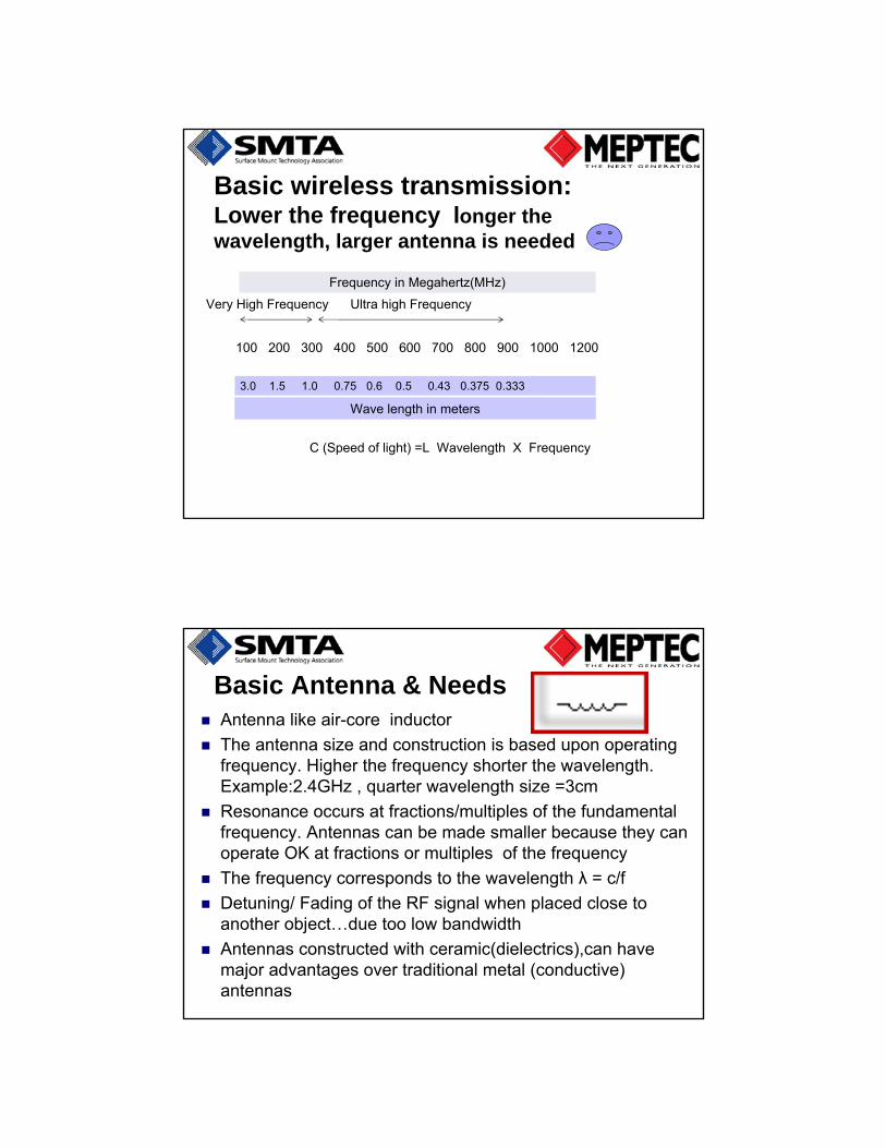
Frequency in Megahertz(MHz)
Very High Frequency Ultra high Frequency
100 200 300 400 500 600 700 800 900 1000 1200
3.0 1.5 1.0 0.75 0.6 0.5 0.43 0.375 0.333
Wave length in meters
C (Speed of light) =L Wavelength X Frequency
Basic wireless transmission: Lower the frequency longer the wavelength, larger antenna is needed
Basic Antenna & Needs Antenna like air-core inductor
The antenna size and construction is based upon operating frequency. Higher the frequency shorter the wavelength. Example:2.4GHz , quarter wavelength size =3cm
Resonance occurs at fractions/multiples of the fundamental frequency. Antennas can be made smaller because they can operate OK at fractions or multiples of the frequency
The frequency corresponds to the wavelength λ = c/f
Detuning/ Fading of the RF signal when placed close to another object…due too low bandwidth
Antennas constructed with ceramic(dielectrics),can have major advantages over traditional metal (conductive) antennas

Basic Antenna types
Antennas common to Medical devices: Monopole
Dipole
Types:Metal Telescopic
Loop, whip
Flat Wire or helix
Printed PCB
Ceramic/Chip
Patch
Antennas rule the air space!

Inside a medical device: challenging high density circuitry

Ceramic Antenna introduction Effective wavelength of a radio wave is shorter in a
ceramic dielectric material than in free space
Therefore Antennas constructed with Ceramic dielectrics can be made smaller than conventional metal antennas.
Many medical devices made with high density circuits require very small size antennas, good efficiency
New low loss Ceramics can be used to construct an antenna with some nice advantages:
Antenna size can be reduced by 10 to 20 times
Multi – tuning capability
Surface mountable
Radiates efficiently since the size is comparable with the half-wavelength dipole antenna
Ceramic Antenna construction
Antennas construction problem.. the size is a fraction of the wavelength effecting the bandwidth(lowering)
However Antenna size can be decreased by increasing the dielectric or magnetic constant ε around the antenna
An Antenna dimension should be ~ = λ/4√ε, where λ is the wave length and ε the Dielectric Constant of the media.
Example, For Frequency= 300 MHz, λ = 1 meter. In Air, ε = 1, so the equivalent antenna should measure a large electrical length of 250mm

Ceramic Antenna at Medical Freq.
Example: Antenna operating @ Medical Freq. 403MHz in air
Requires a wavelength of this frequency of ~750mm
Therefore a ½ wave dipole antenna would need to be a large electrical length of about 375mm or >1 foot in length!
Not practical for most medical devices
Using Ceramic Antenna the electrical length(size) can be decreased by use a low permittivity ceramic dielectric around the antenna
Why is Ceramic antenna smaller ? Using ceramic dielectric material greatly impacts the
effective length of the antenna by a factor of √ε
So for example, if the dielectric ε is = 400 , √400 = 20 . Therefore the antenna length can be reduced by up to 20X fitting is a smaller space inside the device
Higher the dielectric constant results in higher electrical losses. Dielectric material used in Vishay Compact Ceramic antenna is a compromise between Dielectric constant and losses.

Benefits: Patient centered wireless medical device communication Smaller Devices using a ceramic antenna can
facilitate remote monitoring of patients vital signs or download patient history for the clinician
Wireless Neurostimulator devices with small antenna not only monitor but can program devices to move artificial limbs
Wireless capability provides fast data access which can reduce health care cost and provide better treatment actions
FINDINGS: People accessing their charts took better care of themselves… California HealthCare Foundation (CHCF). April 2010
Device benefits
Small Wireless medical devices can be worn on the body or implanted with embedded antenna
Antenna in wireless medical devices allow : 2-way communication system between device and
external control unit or directly to nurse station
Capability for close-range and long-range data exchange so the clinician can respond quickly and efficient
Most implantable devices provide short range communicate to bedside receivers which in turn are connected to the internet for longer range communication

Wireless communication implantable devices
Freq. Medical devicesShort distance applications
Type Frequency Distance
Bluetooth , Wi-Fi and Zigbee
900MHz, 2.4GHz, 5.8GHz
60 meters
Medical Body Networks or PAN- Personal Area
2.4GHz 1 meter
Ultra -Wideband >500MHz 1 meter & >
MMN- Medical Micropower Networks
413-457MHz 1 meter
MICS- Medical Implant Communications Systems
401-406MHz 2-4 meters
Inductive Implants
<200KHz <<1meter

Freq. Medical devices Long distance applications
Type Frequency Distance
WiMax 2.5GHz >1000 meters
WMTSWireless Medical
Telemetry Systems
600MHz to 1.4GHz 60 meters
Wireless Medical Communication
Implantable devices; operate in MICS , MEDS and MMN band
Non-implanted devices; For example Robots operate in WMTS (Wireless Medical Telemetry Service) band or IEEE standard 802.15.4

Telemetry systems for Medical devices
Some medical devices use multiple frequencies: Robots used in hospitals use:
Antenna Frequency( 400, 868, 915MHz) per IEEE standard 802.15.4
Implant devices use MICS band 401-406 MHz combined with multiple higher frequency ISM bands (Industrial, Scientific and Medical)2.4-2.5 GHz +.
Multiple frequencies can better meet power budgets
Multiple-frequency band telemetry have different carrier frequencies for the power and data signals.
MICS Channel spacing
The maximum transmit power for MICs is very lowEIRP=25milliwatts

Example :Compact Ceramic antenna bandwidth advantage
3MHz
Medical Implant Communication ServiceMICS 402–405 MHz, setup by FCCMICS provides up to 10 channels with
bandwidth of 3MHz Vishay Antenna in monitor Solves Detuning Vishay antenna covers a 100MHz bandwidth !
MICS solutions:Use a radio-frequency (RF) link to achieve
high data rates 800/400/200 Kb/sec range of ~ 2-4 meters
Example :Vishay antenna tuned to a center frequency of 400-MHz

Ceramic Chip Antenna features• Tunable across the UHF band
• Small outline SMD 10 x 15 x 1mm35 x 5 x 1.2mm
• Omni directional, linear polarization• Optimized with tuning circuit & ground plane
• 50 Ohm unbalanced interface• Operating Temperature Range:
• -40°C to +85°C• RoHS compliant
• High Dielectric Constant Ceramic•Vishay Proprietary ceramic formulation
• Low Loss Factor• Ideal for medical devices MICS, MMN and
WMTS bands
Vishay Antenna can transmit & receive signals in the UHF band(400MHz -860MHz) and
up to 1.1GHz
Wide Band Tuning with Vishay Compact Ceramic antenna Compact
Ceramic Antenna
• Easy to tune using only two Digital Control lines
• No Software Overloading
• Covers the entire UHF Band (470 MHz to 860 MHz)
•Can be adapted to cover other frequencies

Digital Tuning circuit concept: Switch reactance to generate the
appropriate tuning impedance.
D0 D1 Z
0 0 Z1+Z2
0 1 Z1
1 0 Z2
1 1 0
Tuning circuit application: use low cost PIN diodes as switches.
Digital In1
Digital In2
PIN 0 PIN 1
0 0 High Z
High Z
0 1 High Z
2Ω
1 0 2Ω High Z
1 1 2Ω 2Ω
Compact Ceramic Antenna

How Tuning Works
470 MHz 860 MHzFrequency
1
1
Antenna
How Tuning Works
470 MHz 860 MHzFrequency
0
1
Antenna

How Tuning Works
470 MHz 860 MHzFrequency
1
0
Antenna
How Tuning Works
470 MHz 860 MHzFrequency
0
0
Antenna
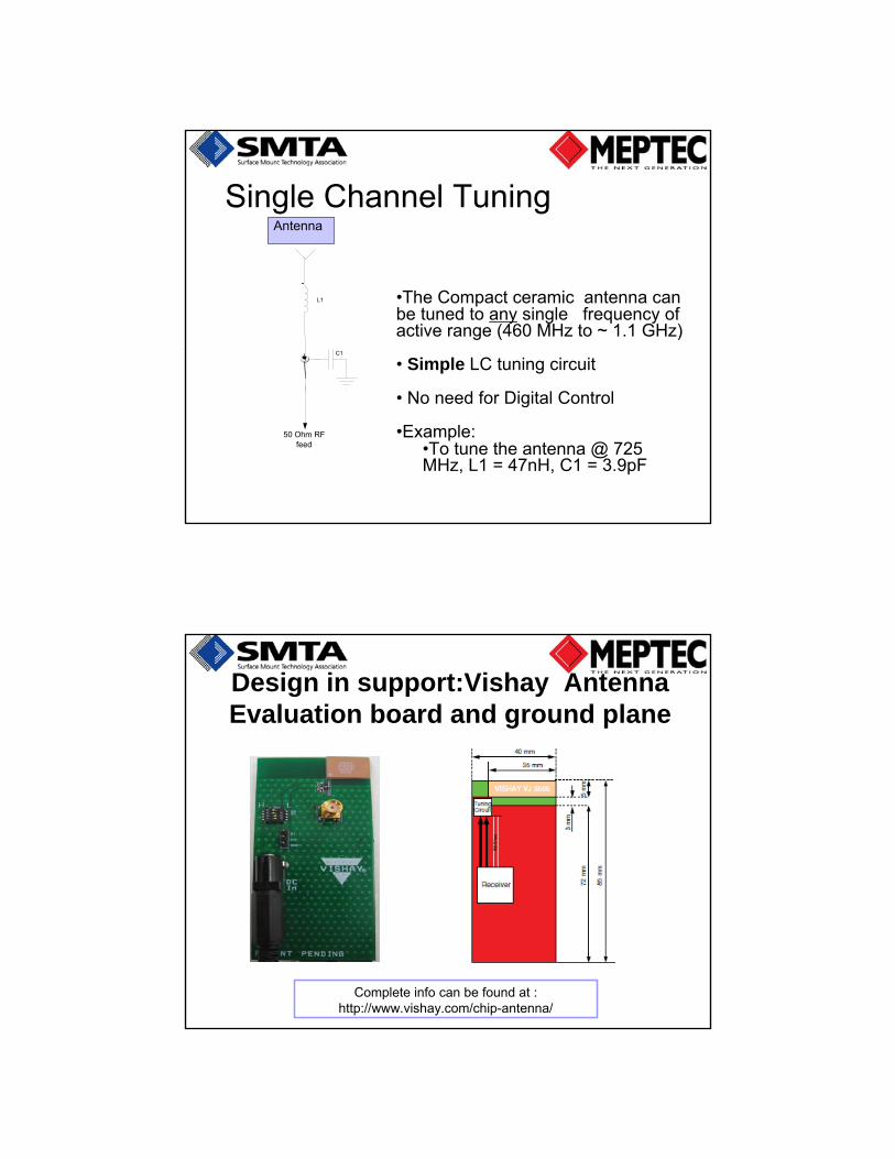
Single Channel Tuning
50 Ohm RFfeed
L1
C1
Antenna
•The Compact ceramic antenna can be tuned to any single frequency of active range (460 MHz to ~ 1.1 GHz)
• Simple LC tuning circuit
• No need for Digital Control
•Example: •To tune the antenna @ 725 MHz, L1 = 47nH, C1 = 3.9pF
Design in support:Vishay Antenna Evaluation board and ground plane
Complete info can be found at :http://www.vishay.com/chip-antenna/
Summary -Compact Antenna for Medical Wireless Applications
Medical Devices with wireless capability will increase even more because of the Patient / Physician benefits
Remote monitoring for wireless control of therapeutic medical devices is a reliable, robust method and can be implemented at multiple frequencies
MICS and newly announced MMN frequency bands are safe, and effective for medical implantable devices
Antenna efficiency should be considered especially where space is constrained for the ground plane.
Vishay Compact Ceramic antenna offer significant advantages over conductive metal antennas