COMP2121: Microprocessors and Interfacinghuiw/comp2121-17s2/Week3/wk3.pdf · • The only...
119
1 1 COMP2121: Microprocessors and Interfacing AVR Assembly Programming (I) Basic AVR Instructions http://www.cse.unsw.edu.au/~cs2121 Lecturer: Hui Wu Session 2, 2017
Transcript of COMP2121: Microprocessors and Interfacinghuiw/comp2121-17s2/Week3/wk3.pdf · • The only...

1
1
COMP2121: Microprocessors and
Interfacing
AVR Assembly Programming (I)
Basic AVR Instructions
http://www.cse.unsw.edu.au/~cs2121
Lecturer: Hui Wu
Session 2, 2017

2
2
• Arithmetic and Logic Instructions
• Control instructions
• Data transfer instructions
• Bit and bit test instructions
• Sample AVR assembly programs
Contents

3
3
AVR Instruction Overview
• Load/store architecture
• At most two operands in each instruction
• Most instructions are two bytes long
• Some instructions are 4 bytes long
• Four Categories:
Arithmetic and logic instructions
Program control instruction
Data transfer instruction
Bit and bit test instructions

4
4
Selected Arithmetic and Logic
Instructions
• Addition instructions: add (addition), adc (addition with carry), inc
(increment)
• Subtraction instructions: sub (subtraction), sbc (subtraction with
carry), dec (decrement)
• Multiplication instructions: mul (unsigned*unsigned) , muls
(signed*signed), mulsu (signed*unsigned)
• Logic instructions: and (logical and), or (logical or), eor (logical
exclusive or)
• Others: clr (clear register), ser (set register), tst (test for zero or
negative), com (1’s complement), neg (2’s complement)
• Refer to the AVR Instruction Set for the complete list of instructions.

5
5
Selected Program Control Instructions
• Unconditional jump: jmp, rjmp, ijmp
• Subroutine call: rcall, icall, call
• Subroutine and interrupt return: ret, reti
• Conditional branching: breq, brne, brsh, brlo, brge, brlt,
brvs, brvc, brie, brid
• Refer to the AVR Instruction Set for a complete list.

6
6
• Copy instructions: mov, movw
• Load instructions: ldi, ld, ldd, lds
• Store instructions: st, std, sts
• Load program memory: lpm
• I/O instructions: in, out
• Stack instructions: push, pop
Selected Data Transfer Instructions

7
7
AVR Program Memory and Data
Memory
16 Bits
32 general purpose
registers
0x0000
0x1F
64 input/output
registers
Internal SRAM
(128~4K bytes)
External SRAM
0x20
0x5F
End Address
0x0000
End Address
Program Memory Data Memory
0x60
8 bits
Program flash memory
(1K bytes~128K bytes)

8
8 8
A Global Picture of Data Transfer
Instructions
General registers
SRAM or
extended I/O FLASH
I/O space Stack
st, std, sts
mov, movw
lpm
push pop
ld, ldd, lds
out
in
Constant
ldi

9
9 9
Selected Shift and Bit-set Instructions
• Shift instructions: lsl, lsr, rol, ror, asr
• Bit-set Instructions: bset, bclr, sbi, cbi, bst, bld, sex, clx,
nop, sleep, wdr, break
• Refer to the AVR Instruction Set for a complete list.

10
10
Add without Carry
• Syntax: add Rd, Rr
• Operands: Rd, Rr {r0, r1, …, r31}
• Operation: RdRd + Rr
• Flags affected: H, S, V, N, Z, C
• Encoding: 0000 11rd dddd rrrr
• Words: 1
• Cycles: 1
• Example: add r1, r2 ; Add r2 to r1
add r28, r28 ; Add r28 to itself

11
11
Add with Carry (1/2)
• Syntax: adc Rd, Rr
• Operands: Rd, Rr {r0, r1, …, r31}
• Operation: RdRd + Rr + C
• Flags affected: H, S, V, N, Z, C
• Encoding: 0001 11rd dddd rrrr
• Words: 1
• Cycles: 1
• Example: Add r1 : r0 to r3 : r2
add r2, r0 ; Add low byte
adc r3, r1 ; Add high byte
• Comments: adc is used in multi-byte addition.

12
12
Add with Carry (2/2)
• When adding two n byte integers, use add to add bytes 0, then use adc to add bytes 1, bytes 2, …, bytes n–1.
• Example: Assume that an integer x is stored in registers r5:r4:r3:r2, and an integer y is stored in registers r10:r9:r8:r7, where the left–most register stores the most significant bye and the right–most register stores the least significant byte.
add r7, r2 ; Add bytes 0
adc r8, r3 ; Add bytes 1
adc r9, r4 ; Add bytes 2
adc r10, r5 ; Add bytes 3

13
13
Increment
• Syntax: inc Rd
• Operands: Rd {r0, r1, …, r31}
• Operation: RdRd+1
• Flags affected: S, V, N, Z
• Encoding: 1001 010d dddd 1011
• Words: 1
• Cycles: 1
• Example: clr r22 ; clear r22
loop: inc r22 ; Increment r22
cpi r22, $4F ; compare r22 to $4F
brne loop ; Branch to loop if not equal
nop ; Continue (do nothing

14
14
Subtract without Carry
• Syntax: sub Rd, Rr
• Operands: Rd, Rr {r0, r1, …, r31}
• Operation: RdRd–Rr
• Flags affected: H, S, V, N, Z, C
• Encoding: 0001 10rd dddd rrrr
• Words: 1
• Cycles: 1
• Example: sub r13, r12 ; Subtract r12 from r13

15
15
Subtract with Carry (1/2)
• Syntax: sbc Rd, Rr
• Operands: Rd, Rr {r0, r1, …, r31}
• Operation: RdRd–Rr–C
• Flags affected: H, S, V, N, Z, C
• Encoding: 0000 10rd dddd rrrr
• Words: 1
• Cycles: 1
• Example: Subtract r1:r0 from r3:r2
sub r2, r0 ; Subtract low byte
sbc r3, r1 ; Subtract with carry high byte
Comments: sbc is used in multi-byte subtraction

16
16
Subtract with Carry (2/2)
• When subtracting one n byte integer from another n byte integer, use sub to subtract bytes 0, then use sbc to subtract bytes 1, bytes 2, …, bytes n–1.
• Example: Assume that an integer x is stored in registers r5:r4:r3:r2, and an integer y is stored in registers r10:r9:r8:r7, where the left–most register stores the most significant bye and the right–most register stores the least significant byte.
sub r7, r2 ; subtract bytes 0
sbc r8, r3 ; subtract bytes 1
sbc r9, r4 ; subtract bytes 2
sbc r10, r5 ; subtract bytes 3

17
17
Decrement
• Syntax: dec Rd
• Operands: Rd {r0, r1, …, r31}
• Operation: RdRd–1
• Flags affected: S, V, N, Z
• Encoding: 1001 010d dddd 1010
• Words: 1
• Cycles: 1
• Example: ldi r17, $10 ; Load constant in r17
loop: add r1, r2 ; Add r2 to r1
dec r17 ; Decrement r17
brne loop; ; Branch to loop if r170
nop ; Continue (do nothing)

18
18
Multiply Unsigned
• Syntax: mul Rd, Rr
• Operands: Rd, Rr {r0, r1, …, r31}
• Operation: r1, r0Rr*Rd (unsignedunsigned * unsigned )
• Flags affected: Z, C
• Encoding: 1001 11rd dddd rrrr
• Words: 1
• Cycles: 2
• Example: mul r6, r5 ; Multiply r6 and r5
mov r6, r1
mov r5, r0 ; Copy result back in r6 : r5

19
19
Multiply Signed
• Syntax: muls Rd, Rr
• Operands: Rd, Rr {r16, r17, …, r31}
• Operation: r1, r0Rr*Rd (signedsigned * signed )
• Flags affected: Z, C
• Encoding: 0000 0010 dddd rrrr
• Words: 1
• Cycles: 2
• Example: mul r17, r16 ; Multiply r17 and r16
movw r17:r16, r1:r0 ; Copy result back to r17 : r16

20
20
Multiply Signed with Unsigned
• Syntax: mulsu Rd, Rr
• Operands: Rd, Rr {r16, r17, …, r23}
• Operation: r1, r0Rr*Rd (signedsigned * unsigned )
• Flags affected: Z, C
C is set if bit 15 of the result is set; cleared otherwise.
• Encoding: 0000 0011 0ddd 0rrr
• Words: 1
• Cycles: 2

21
21
An Example of Using Multiply
Instructions (1/2)
Multiply two unsigned 16-bit numbers stored in r23:r22 and r21:r20,
respectively, and store the 32-bit result in r19:r18:r17:r16.
How to do it?
Let ah and al be the high byte and low byte, respectively, of the multiplicand
and bh and bb the high byte and low byte, respectively, of the multiplier.
ah : al * bh : bl
= (ah* 28+ al) * (bh* 28+bl) = ah*bh*216 + al*bh* 28 + ah*bl*28 + al*bl

22
22
mul16x16_32:
clr r2
mul r23, r21 ; (unsigned) ah * (unsigned) bh
movw r19 : r18, r1 : r0 ; move the result of ah * bh to r19:r18
mul r22, r20 ; (unsigned) al * (unsigned) bl
movw r17 : r16, r1: r0 ; move the result of al * bl to r17:r16
mul r23, r20 ; (unsigned) ah * (unsigned) bl
add r17, r0
adc r18, r1
adc r19, r2
mul r21, r22 ; (unsigned) bh * (unsigned) al
add r17, r0
adc r18, r1
adc r19, r2
ret ; return to the caller
An Example of Using Multiply
Instructions (2/2)

23
23
Bitwise AND
• Syntax: and Rd, Rr
• Operands: Rd, Rr {r0, r1, …, r31}
• Operation: RdRr · Rd (Bitwise AND Rr and Rd)
• Flags affected: S, V, N, Z
• Encoding: 0010 00rd dddd rrrr
• Words: 1
• Cycles: 1
• Example:
ldi r20, 0b00110101
ldi r16, 1
and r20, r16 ; r20=0b00000001

24
24
Bitwise OR
• Syntax: or Rd, Rr
• Operands: Rd, Rr {r0, r1, …, r31}
• Operation: RdRr v Rd (Bitwise OR Rr and Rd)
• Flags affected: S, V, N, Z
• Encoding: 0010 10rd dddd rrrr
• Words: 1
• Cycles: 1
• Example:
ldi r15, 0b11110000
ldi r16, 0b00001111
or r15, r16 ; Do bitwise or between registers
; r15=0b11111111

25
25
Bitwise Exclusive-OR
• Syntax: eor Rd, Rr
• Operands: Rd, Rr {r0, r1, …, r31}
• Operation: RdRr Rd (Bitwise exclusive OR Rr and Rd)
• Flags affected: S, V, N, Z
• Encoding: 0010 01rd dddd rrrr
• Words: 1
• Cycles: 1
• Example:
eor r4, r4 ; Clear r4
eor r0, r22 ; Bitwise exclusive or between r0 and r22
; If r0=0b10101011 and r22=0b01001000
; then r0=0b11100011

26
26
Clear Bits in Register
• Syntax: cbr Rd, k
• Operands: Rd {r16, r17, …, r31} and 0 k 255
• Operation: RdRd · ($FF-k) (Clear the bits specified by k )
• Flags affected: S, V, N, Z
• Encoding: 0111 wwww dddd wwww (wwwwwwww=$FF-k)
• Words: 1
• Cycles: 1
• Example:
cbr r4, 0b11 ; Clear bits 0 and 1 of r4.

27
27
Compare without Carry
• Syntax: cp Rd, Rr
• Operands: Rd {r0, r1, …, r31}
• Operation: Rd–Rr (Rd is not changed)
• Flags affected: H, S, V, N, Z, C
• Encoding: 0001 01rd dddd rrrr
• Words: 1
• Cycles: 1
• Example:
cp r4, r5 ; Compare r4 with r5
brne noteq ; Branch if r4 r5
...
noteq: nop ; Branch destination (do nothing)
• The only difference between cp and sub is that the result of cp is not stored.
• cp is used immediately before a branch instruction.

28
28
Compare with Carry (1/2)
• Syntax: cpc Rd, Rr
• Operands: Rd {r0, r1, …, r31}
• Operation: Rd–Rr–C (Rd is not changed)
• Flags affected: H, S, V, N, Z, C
• Encoding: 0001 01rd dddd rrrr
• Words: 1
• Cycles: 1
• Example:
; Compare r3:r2 with r1:r0
cp r2, r0 ; Compare low bytes
cpc r3, r1 ; Compare high bytes
brne noteq ; Branch if not equal
...
noteq: nop ; Branch destination (do nothing)

29
29
Compare with Carry (2/2)
• The only difference between cpc and sbc is that the result of cpc is not stored.
• When comparing two n–byte integers, use cp to compare bytes 0, and cpc to compare bytes 1, bytes 2, …, bytes n–1.
• Example: Assume that an integer x is stored in registers r5:r4:r3:r2, and an integer y is stored in registers r10:r9:r8:r7, where the left–most register stores the most significant bye and the right–most register stores the least significant byte.
cp r7, r2 ; compare bytes 0
cpc r8, r3 ; compare bytes 1
cpc r9, r4 ; compare bytes 2
cpc r10, r5 ; compare bytes 3
brne noteq ; if x!=y goto noteq
…
noteq: inc r0

30
30
Compare with Immediate
• Syntax: cpi Rd, k
• Operands: Rd {r16, r17, …, r31} and 0 k 255
• Operation: Rd – k (Rd is not changed)
• Flags affected: H, S, V, N, Z, C
• Encoding: 0011 kkkk dddd kkkk
• Words: 1
• Cycles: 1
• Example:
cpi r19, 30 ; Compare r19 with 30
brne noteq ; Branch if r19 30
...
noteq: nop ; Branch destination (do nothing)

31
31
Test for Zero or Minus
• Syntax: tst Rd
• Operands: Rd {r0, r1, …, r31}
• Operation: RdRd · Rd
• Flags affected: S, V, N, Z
• Encoding: 0010 00dd dddd dddd
• Words: 1
• Cycles: 1
• Example:
tst r0 ; Test r0
breq zero ; Branch if r0=0
...
zero: nop ; Branch destination (do nothing)

32
32
One's Complement
• Syntax: com Rd
• Operands: Rd {r0, r1, …, r31}
• Operation: Rd$FF – Rd
• Flags affected: S, V, N, Z
• Encoding: 1001 010d dddd 0000
• Words: 1
• Cycles: 1
• Example:
com r4 ; Take one's complement of r4
breq zero ; Branch if zero
...
zero: nop ; Branch destination (do nothing)

33
33
Two's Complement
• Syntax: neg Rd
• Operands: Rd {r0, r1, …, r31}
• Operation: Rd$00 – Rd (The value of $80 is left unchanged)
• Flags affected: H, S, V, N, Z, C
H: R3 + Rd3
Set if there is a borrow from bit 3; cleared otherwise
• Encoding: 1001 010d dddd 0001
• Words: 1
• Cycles: 1
• Example: sub r11,r0 ;Subtract r0 from r11
brpl positive ;Branch if result positive
neg r11 ;Take two's complement of r11
positive: nop ;Branch destination (do nothing)

34
34
The following AVR assembly program implements division by using repeated
subtractions. The dividend is stored in in the register r18 and r17, where r18
stores the most significant byte and r17 stores the least significant byte. The
divisor is stored in r19. The quotient is stored in r21 and r20 and the remainder is
stored in r17.
.include “m2560def.inc” ; Include definition file for ATmega2560
.equ dividend=2121 ; Define dividend to be 2121
.def dividend-high=r18 ; Define dividend-high to be r18
.def dividend-low=r17
.def divisor=r19
.def quotient-low=r20
.def quotient-high=r21
.def zero=r16
AVR Assembly Programming:
Example 1 (1/3)

35
35
AVR Assembly Programming:
Example 1 (2/3)
.cseg ; Define a code segment
.org 0x100 ; Set the starting address of code segment to 0x100
ldi dividend-low, low(dividend) ; load r17 with the low byte of the dividend
ldi dividend-high, high(dividend) ; load r18 with the high byte of the dividend
ldi divisor, 45 ; load r19 with 45
clr quotient-low ; quotient-low=0
clr quotient-high ; quotient-high=0
clr zero ; zero=0
36
36
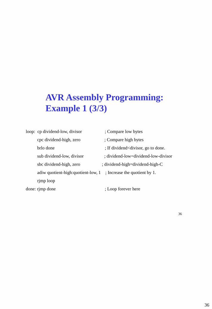
AVR Assembly Programming:
Example 1 (3/3)
loop: cp dividend-low, divisor ; Compare low bytes
cpc dividend-high, zero ; Compare high bytes
brlo done ; If dividend<divisor, go to done.
sub dividend-low, divisor ; dividend-low=dividend-low-divisor
sbc dividend-high, zero ; dividend-high=dividend-high-C
adiw quotient-high:quotient-low, 1 ; Increase the quotient by 1.
rjmp loop
done: rjmp done ; Loop forever here

37
37
ARV Assembly Programming:
Example 2 (1/5)
Convert the following C program into an AVR assembly program:
unsigned int i, sum;
void main()
{
sum=0;
for (i =1; i<100; i++)
sum=sum+i;
}

38
38
ARV Assembly Programming:
Example 2 (2/5)
We can use general registers to store i and sum.
Question: How many general registers are needed to store i and sum, respectively?
Answer: One general register for i and two general registers for sum. Why?
• The maximum unsigned number stored in one AVR general register is 11111111b
= 28 – 1 = 255.
• The maximum unsigned number stored in two AVR general registers is 11111111
11111111b = 216-1 = 65535.
We use r10 to store i and r12:r11 to store sum.

39
39
ARV Assembly Programming:
Example 2 (3/5)
To understand the structure of for loop, we convert the C program into an equivalent
program:
unsigned int i, sum;
void main()
{
sum=0;
i=1;
forloop: sum=sum+i;
i=i+1;
if ( i<100)
goto forloop;
}

40
40
ARV Assembly Programming:
Example 2 (4/5)
unsigned int i, sum;
void main()
{
sum=0;
i=1;
.include “m2560def.inc” ; Include definition file
for Mega64
.def zero=r0 ; Define i to be r0
.def i=r16 ; Define i to be r16
.def sum-h=r12 ; Define sum-h to be r12
.def sum-l=r11 ; Define sum-l to be r11
.cseg
clr zero ; zero is used to sign-extend i
clr sum-h
clr sum-l
ldi i, 1 ; Note that i must be in r16-r31

41
41
ARV Assembly Programming:
Example 2 (5/5)
forloop: sum=sum+i;
i=i+1;
if ( i<100)
goto forloop;
}
forloop: add sum-l, i ; Add bytes 0
adc sum-h, zero ; Add bytes 1
inc i ; Increment loop counter
cpi i, 100
brlo forloop
loopforever: rjmp loopforever

42
42
Jump
• Syntax: jmp k
• Operands: 0 ≤ k < 4M
• Operation: PCk
• Flag affected: None
• Encoding: 1001 010k kkkk 110k
kkkk kkkk kkkk kkkk
• Words: 2
• Cycles: 3
• Example:
mov r1, r0 ; Copy r0 to r1
jmp farplc ; Unconditional jump
...
farplc: inc r20 ; Jump destination

43
43
Relative Jump
• Syntax: rjmp k
• Operands: -2K ≤ k < 2K
• Operation: PCPC+k+1
• Flag affected: None
• Encoding: 1100 kkkk kkkk kkkk
• Words: 1
• Cycles: 2
• Example:
cpi r16, $42 ; Compare r16 to $42
brne error ; Branch to error if r16 $42
rjmp ok ; jump to ok
error: add r16, r17 ; Add r17 to r16
inc r16 ; Increment r16
ok: mov r2, r20 ; Jump destination

44
44
Indirect Jump (1/2)
• Syntax: ijmp
• Operation:
(i) PCZ(15:0) Devices with 16 bits PC, 128K bytes program memory maximum.
(ii) PC(15:0)Z(15:0)Devices with 22 bits PC, 8M bytes
program memory maximum.
PC(21:16) <- 0
• Flag affected: None
• Encoding: 1001 0100 0000 1001
• Words: 1
• Cycles: 2

45
45
Indirect Jump (2/2)
• Example:
clr r10 ; Clear r10
ldi r20, 2 ; Load jump table offset
ldi r30, low(Lab<<1) ; High byte of the starting address (base) of jump table
ldi r31, high(Lab<<1) ; Low byte of the starting address (base) of jump table
add r30, r20
adc r31, r10 ; Base + offset is the address of the jump table entry
lpm r0, Z+ ; Load low byte of the the jump table entry
lpm r1, Z ; Load high byte of the jump table entry
movw r31:r30, r1:r0 ; Set the pointer register Z to point the target instruction
ijmp ; Jump to the target instruction
…
Lab: .dw jt_l0 ; The first entry of the jump table
.dw jt_l1 ; The second entry of the jump table
…
jt_l0: nop
jt_l1: nop
…

46
46
Branch If Equal
• Syntax: breq k
• Operands: -64 ≤ k < 63
• Operation: If Rd = Rr (Z = 1) then PC PC + k + 1, else PC PC + 1
• Flag affected: None
• Encoding: 1111 00kk kkkk k001
• Words: 1
• Cycles: 1 if condition is false
2 if conditional is true
• Example:
cp r1, r0 ; Compare registers r1 and r0
breq equal ; Branch if registers equal
...
equal: nop ; Branch destination (do nothing)

47
47
Branch If Same or Higher (Unsigned)
• Syntax: brsh k
• Operands: -64 ≤ k < 63
• Operation: if Rd Rr (unsigned comparison) then PC PC + k + 1, else PC PC + 1
• Flag affected: none
• Encoding: 1111 01kk kkkk k000
• Words: 1
• Cycles: 1 if condition is false
2 if conditional is true
• Example:
sbi r26, $56 ; subtract $56 from r26
brsh test ; branch if r26 $56
...
Test: nop ; branch destination
…

48
48
Branch If Lower (Unsigned)
• Syntax: brlo k
• Operands: -64 ≤ k < 63
• Operation: If Rd < Rr (unsigned comparison) then PC PC + k + 1, else PC PC + 1
• Flag affected: None
• Encoding: 1111 00kk kkkk k000
• Words: 1
• Cycles: 1 if condition is false
2 if conditional is true
• Example:
eor r19, r19 ; Clear r19
loop: inc r19 ; Increase r19
...
cpi r19, $10 ; Compare r19 with $10
brlo loop ; Branch if r19 < $10 (unsigned)
nop ; Exit from loop (do nothing)

49
49
Branch If Less Than (Signed)
• Syntax: brlt k
• Operands: -64 ≤ k < 63
• Operation: If Rd < Rr (signed comparison) then PC PC + k + 1, else PC PC + 1
• Flag affected: None
• Encoding: 1111 00kk kkkk k100
• Words: 1
• Cycles: 1 if condition is false
2 if conditional is true
• Example:
cp r16, r1 ; Compare r16 to r1
brlt less ; Branch if r16 < r1 (signed)
...
less: nop ; Branch destination (do nothing)

50
50
Branch If Greater or Equal (Signed)
• Syntax: brge k
• Operands: -64 ≤ k < 63
• Operation: If Rd Rr (signed comparison) then PC PC + k + 1, else PC PC + 1
• Flag affected: None
• Encoding: 1111 01kk kkkk k100
• Words: 1
• Cycles: 1 if condition is false
2 if conditional is true
• Example:
cp r11, r12 ; Compare registers r11 and r12
brge greateq ; Branch if r11 ≥ r12 (signed)
...
greateq: nop ; Branch destination (do nothing)

51
51
Branch If Overflow Set
• Syntax: brvs k
• Operands: -64 ≤ k < 63
• Operation: If V=1 then PC PC + k + 1, else PC PC + 1
• Flag affected: None
• Encoding: 1111 00kk kkkk k011
• Words: 1
• Cycles: 1 if condition is false
2 if conditional is true
• Example:
add r3, r4 ; Add r4 to r3
brvs overfl ; Branch if overflow
...
overfl: nop ; Branch destination (do nothing)

52
52
Branch If Overflow Clear
• Syntax: brvc k
• Operands: -64 ≤ k < 63
• Operation: If V=0 then PC PC + k + 1, else PC PC + 1
• Flag affected: None
• Encoding: 1111 01kk kkkk k011
• Words: 1
• Cycles: 1 if condition is false
2 if conditional is true
• Example:
add r3, r4 ; Add r4 to r3
brvs noover ; Branch if no overflow
...
noover: nop ; Branch destination (do nothing)

53
53
Branch if Global Interrupt is Enabled
• Syntax: brie k
• Operands: -64 ≤ k < 63
• Operation: If I=1 then PC PC + k + 1, else PC PC + 1
• Flag affected: None
• Encoding: 1111 00kk kkkk k111
• Words: 1
• Cycles: 1 if condition is false
2 if conditional is true
• Example:
brvs inten ; Branch if the global interrupt is enabled
...
inten: nop ; Branch destination (do nothing)

54
54
Branch if Global Interrupt is Disabled
• Syntax: brid k
• Operands: -64 ≤ k < 63
• Operation: If I=0 then PC PC + k + 1, else PC PC + 1
• Flag affected: None
• Encoding: 1111 00kk kkkk k111
• Words: 1
• Cycles: 1 if condition is false
2 if conditional is true
• Example:
brid intdis ; Branch if the global interrupt is enabled
...
intdis: nop ; Branch destination (do nothing)

55
55
Signed Branching vs. Unsigned
Branching (1/2)
Consider the following AVR assembly code:
ldi r10, low(-1)
ldi r11, high(-1)
ldi r20, low(0x500)
ldi r21, high(0x500)
cp r11, r21
cpc r10, r20
brge comp9032
clr r0
rjmp end
comp9032: ldi r0, 1
end: nop
What is the value in register r0 after the above sequence of code is executed?

56
56
Signed Branching vs. Unsigned
Branching (2/2)
Consider the following AVR assembly code:
ldi r10, low(-1)
ldi r11, high(-1)
ldi r20, low(0x500)
ldi r21, high(0x500)
cp r11, r21
cpc r10, r20
brsh comp9032
clr r0
rjmp end
comp9032: ldi r0, 1
end: nop
What is the value in register r0 after the above sequence of code is executed?

57
57
AVR Assembly Programming:
Example 3 (1/4)
Convert the following C program into an AVR assembly program:
int x, z; /* Assume that the size of a signed integer is two bytes */
short int y; /* Assume that the size of a signed short integer is one byte */
void main()
{
if (x<y)
z=x-y;
else
z=x+y;
}

58
58
AVR Assembly Programming:
Example 3 (2/4)
int x, z;
short int y;
.include “m2560def.inc” ; Include definition
file for Mega64
.def x-h=r12 ; Define x-h to be r12
.def x-l=r11 ; Define x-l to be r11
def z-h=r14 ; Define z-h to be r14
.def z-l=r13 ; Define z-l to be r13
.def y=r16 ; Define y to be r16
.def temp=r17 ; Define temp to be r0
; temp is used to sign-extend y

59
59
AVR Assembly Programming:
Example 3 (3/4)
void main()
{
if (x<y)
.cseg
cpi y, 0 ; Sign extend y
brlt negative ; Signed-extended y is stored
clr temp ; in the register pair temp:y
rjmp next
negative: ldi temp, $FF
mov z-l, x-l ; Copy x to z
mov z-h, x-h
cp x-l, y ; Compare x with y
cpc x-h, temp
brge elsepart

60
60
AVR Assembly Programming:
Example 3 (4/4)
z=x-y;
else
z=x+y;
}
sub z-l, y
sbc z-h, temp
rjmp end;
elsepart:
add z-l, y
adc z-l, temp
end: rjmp end; ; Loop forever here

61
61
Copy Register
• Syntax: mov Rd, Rr
• Operands: Rd, Rr {r0, r1, …, r31}
• Operation: RdRr
• Flag affected: None
• Encoding: 0010 11rd dddd rrrr
• Words: 1
• Cycles: 1
• Example:
mov r1, r0 ; Copy r0 to r1

62
62
Copy Register Pair
• Syntax: movw Rd+1:Rd, Rr+1:Rr
• Operands: d, r {0, 2, …, 28, 30}
• Operation: Rd+1:RdRr+1:Rr
• Flag affected: None
• Encoding: 0000 0001 dddd rrrr
• Words: 1
• Cycles: 1
• Example:
movw r21:r20, r1:r0 ; Copy r1:r0 to r21:r20

63
63
Load Immediate
• Syntax: ldi Rd, k
• Operands: Rd{r16, r17, …, r31} and 0 ≤ k 255
• Operation: Rdk
• Flag affected: None
• Encoding: 1110 kkkk dddd kkkk
• Words: 1
• Cycles: 1
• Example:
ldi r16, $42 ; Load $42 to r16

64
64
Load Indirect
• Syntax: ld Rd, v
• Operands: Rd{r0, r1, …, r31} and v{x, x+, -x, y, y+, -y, z, z+, -z}
• Operation: (i) Rd(v) if v {x, y, z}
(ii) xx-1 and Rd(x) if v =-x
yy-1 and Rd(y) if v =-y
zz-1 and Rd(z) if v =-z
(iii) Rd(x) and xx+1 if v =x+
Rd(y) and yy+1 if v =y+
Rd(z) and zz+1 if v =z+
• Flag affected: None
• Encoding: Depends on v. Refer to AVR Instruction Set for details
• Words: 1
• Cycles: 2
• Comments: Post-inc and pre-dec are used to load contiguous data.

65
65
Load Indirect with Displacement
• Syntax: ldd Rd, v
• Operands: Rd{r0, r1, …, r31} and v{y+q, z+q}
• Operation: Rd(v)
• Flag affected: None
• Encoding: Depends on v. Refer to AVR Instruction Set for details
• Words: 1
• Cycles: 2
• Example: clr r31 ; Clear Z high byte
ldi r30, $60 ; Set Z low byte to $60
ld r0, Z+ ; Load r0 with data space loc. $60(Z post inc)
ld r1, Z ; Load r1 with data space loc. $61
ldi r30, $63 ; Set Z low byte to $63
ld r2, Z ; Load r2 with data space loc. $63
ld r3, -Z ; Load r3 with data space loc. $62(Z pre dec)
ldd r4, Z+2 ; Load r4 with data space loc. $64
• Comments: ldd is used to load an element of a structure.

66
66
Load direct
• Syntax: lds Rd, k
• Operands: Rd{r0, r1, …, r31} and 0 k 65535
• Operation: Rd(k)
• Flag affected: None
• Encoding: 1001 000d dddd 0000 kkkk kkkk kkkk kkkk
• Words: 2
• Cycles: 2
• Example:
lds r2, $FF00 ; Load r2 with the contents of data space location $FF00
inc r2 ; add r2 by 1
sts $FF00, r2 ; Write back

67
67
Store Indirect
• Syntax: st v, Rr
• Operands: Rr{r0, r1, …, r31} and v{x, x+, -x, y, y+, -y, z, z+, -z}
• Operation: (i) (v)Rr if v {x, y, z}
(ii) xx-1 and (x)Rr if v =-x
yy-1 and (y)Rr if v =-y
zz-1 and (z)Rr if v =-z
(iii) (x)Rr and xx+1 if v =x+
(y)Rr and yy+1 if v =y+
(z)Rr and zz+1 if v =z+
• Flag affected: None
• Encoding: Depends on v. Refer to AVR Instruction Set for details
• Words: 1
• Cycles: 2
• Comments: Post-inc and pre-dec are used to store contiguous data.

68
68
Store Indirect with Displacement
• Syntax: std v, Rr
• Operands: Rd{r0, r1, …, r31} and v{y+q, z+q}
• Operation: (v)Rr
• Flag affected: None
• Encoding: Depends on v. Refer to AVR Instruction Set for details
• Words: 1
• Cycles: 2
• Example:
clr r29 ; Clear Y high byte
ldi r28, $60 ; Set Y low byte to $60
st Y+, r0 ; Store r0 in data space loc. $60(Y post inc)
st Y, r1 ; Store r1 in data space loc. $61
ldi r28, $63 ; Set Y low byte to $63
st Y, r2 ; Store r2 in data space loc. $63
st -Y, r3 ; Store r3 in data space loc. $62 (Y pre dec)
std Y+2, r4 ; Store r4 in data space loc. $64
• Comments: std is used to store an element of a structure.

69
69
Store direct
• Syntax: sts k, Rr
• Operands: Rr{r0, r1, …, r31} and 0 k 65535
• Operation: (k)Rr
• Flag affected: None
• Encoding: 1001 001d dddd 0000 kkkk kkkk kkkk kkkk
• Words: 2
• Cycles: 2
• Example:
lds r2, $FF00 ; Load r2 with the contents of data space location $FF00
add r2, r1 ; add r1 to r2
sts $FF00, r2 ; Write back

70
70
Load Program Memory (1/3)
• Syntax: Operands: Operations:
(i) LPM None, R0 implied R0(Z)
(ii) LPM Rd, Z 0 ≤ d ≤ 31 Rd(Z)
(iii) LPM Rd, Z+ 0 ≤ d ≤ 31 Rd(Z)
• Flag affected: None
• Encoding: (i) 1001 0101 1100 1000
(ii) 1001 000d dddd 0100
(iii) 1001 000d dddd 0101
• Words: 1
• Cycles: 3
• Comments: Z contains the byte address while the flash memory uses
word addressing. Therefore, the word address must be converted into
byte address before having access to data on flash memory.

71
71
Load Program Memory (2/3)
• Example
ldi zh, high(Table_1<<1) ; Initialize Z pointer
ldi zl, low(Table_1<<1)
lpm r16, z+ ; r16=0x76
lpm r17, z ; r17=0x58
...
Table_1: .dw 0x5876
…
• Comments: Table_1<<1 converts word address into byte address

72
72
Load Program Memory (3/3)
• Example
ldi zh, high(Table_1<<1) ; Initialize Z pointer
ldi zl, low(Table_1<<1)
lpm r16, z+ ; r16=0x76
lpm r17, z ; r17=0x58
...
Table_1: .dw 0x5876
…
Comments: Table_1<<1, i.e. Table*2, converts the word address of
0x5876 into the byte address.

73
73
Load an I/O Location to Register
• Syntax: in Rd, A
• Operands: Rd{r0, r1, …, r31} and 0A63
• Operation: RdI/O (A)
Loads one byte from the location A in the I/O Space (Ports,
Timers, Configuration registers etc.) into register Rd in the register file.
• Flag affected: None
• Encoding: 1011 0AAd dddd AAAA
• Words: 1
• Cycles: 1
• Example:
in r25, $16 ; Read Port B
cpi r25, 4 ; Compare read value to constant
breq exit ; Branch if r25=4
...
exit: nop ; Branch destination (do nothing)

74
74
Store Register to an I/O Location
• Syntax: out A, Rr
• Operands: Rr{r0, r1, …, r31} and 0A63
• Operation: I/O (A)Rr
Store the byte in register Rr to the I/O location (register).
• Flag affected: None
• Encoding: 1011 1AAr rrrr AAAA
• Words: 1
• Cycles: 1
• Example:
clr r16 ; Clear r16
ser r17 ; Set r17 to $ff
out $18, r16 ; Write zeros to Port B
nop ; Wait (do nothing)
out $18, r17 ; Write ones to Port B

75
75
Push Register on Stack
• Syntax: push Rr
• Operands: Rr{r0, r1, …, r31}
• Operation: (SP) Rr
SP SP –1
• Flag affected: None
• Encoding: 1001 001d dddd 1111
• Words: 1
• Cycles: 2
• Example
call routine ; Call subroutine
...
routine: push r14 ; Save r14 on the stack
push r13 ; Save r13 on the stack
...
pop r13 ; Restore r13
pop r14 ; Restore r14
ret ; Return from subroutine

76
76
Pop Register from Stack
• Syntax: pop Rr
• Operands: Rr{r0, r1, …, r31}
• Operation: Rr (SP)
SP SP +1
• Flag affected: None
• Encoding: 1000 000d dddd 1111
• Words: 1
• Cycles: 2
• Example
call routine ; Call subroutine
...
routine: push r14 ; Save r14 on the stack
push r13 ; Save r13 on the stack
...
pop r13 ; Restore r13
pop r14 ; Restore r14
ret ; Return from subroutine

77
77
AVR Assembly Programming: Example 4 (1/3)
The following AVR assembly program converts 5 lower-case letters in a string which stored
in the program memory (FLASH memory) into the upper-case letters and stores the
resulting string into the data memory (SRAM).
.include “m2560def.inc”
.equ size =5 ; Define size to be 5
.def counter =r17 ; Define counter to be r17
.dseg ; Define a data segment
.org 0x100 ; Set the starting address of data segment to 0x100
Cap_string: .byte 5 ; Allocate 5 bytes of data memory (SRAM) to store the string of
; upper-case letters.
.cseg ; Define a code segment
Low_string: .db “hello” ; Define the string “hello” which is stored in the program
; (Flash) memory.

78
78
AVR Assembly Programming: Example 4 (2/3)
ldi zl, low(Low_string<<1) ; Get the low byte of the address of “h”
ldi zh, high(Low_string<<1) ; Get the high byte of the address of “h”
ldi yl, low(Cap_string)
ldi yh, high(Cap_string)
clr counter ; counter=0

79
79
AVR Assembly Programming: Example 4 (3/3)
main:
lpm r20, z+ ; Load a letter from flash memory
subi r20, 32 ; Convert it to the capital letter
st y+,r20 ; Store the capital letter in SRAM
inc counter
cpi counter, size
brlt main
loop: nop
rjmp loop

80
80
AVR Assembly Programming: Example 5 (1/7)
Convert the following C program into an equivalent AVR
Assembly program:
int a[100], max;
int i;
int main()
{
for (i=0; i<100; i++)
a[i]=100*i;
max=a[0];
for (i=1; i<100; i++)
if (a[i]> max) max=a[i];
return 0;
}

81
81
AVR Assembly Programming: Example 5 (2/7)
Data are stored in the SRAM. A one-dimensional array is stored
consecutively in the SRAM, i.e. the element i+1 immediately follows the
element i. The following figure shows how the array a is stored in the
SRAM:
Address 0
1
a a[0]
a[1]
a[2]
a+1
a+2
a+3

82
82
AVR Assembly Programming: Example 5 (3/7)
When a variable is more than one byte long, the programmer needs to use
either big-endian order or little endian order to store its value. In this
example, we use little endian order, i.e. the least significant byte is stored at
the lowest address.
Address 0
1
a a[0]
a[1]
a+1
a+2
a+3
Byte 0 of a[0]
Byte 0 of a[1]
Byte 1 of a[0]
Byte 1 of a[1]

83
83
AVR Assembly Programming: Example 5 (4/7)
int a[100], max;
int i;
int main()
{
.include “m2560def.inc”
.def temp=r21
.def i=r16 ; r16 stores i
.def ai-high=r20 ; ai-high:ai-low temporarily
.def ai-low=r19 ; store a[i]
.def max-high=r18 ; max-high:max:low
def max-low=r17 ; temporarily store max
.dseg.
a: .byte 200 ; Reserve 200 bytes for the array a
max: .byte 2 ; Reserve 2 byte for max
.cseg
ldi xl, low(a) ; Let x pointer point
ldi xh, high(a) ; the start of the array a

84
84
AVR Assembly Programming: Example 5 (5/7)
for (i=0; i<100; i++)
a[i]=100*i;
max=a[0];
clr i ; clear I
ldi temp, 100
forloop1: mul i, temp ; Compute 100*i
st x+, r0 ; a[i]=100*i
st x+, r1
inc i
cpi i, 100
brlt forloop1
ldi xl, low(a) ; Let x pointer point
ldi xh, high(a) ; the start of the array a
ld max-low, x+ ; max=a[0]
ld max-high, x+

85
85
AVR Assembly Programming: Example 5 (6/7)
for (i=1; i<100; i++)
if (a[i]> max)
max=a[i];
ldi i, 1
forloop2: ld ai-low, x+ ; load a[i] into ai-low
ld ai-high, x+ ; and ai-high
cp max-low, ai-low ; Compare max with a[i]
cpc max-high, ai-high
brlt lessthan
rjmp otherwise
lessthan: mov max-low, ai-low
mov max-high, ai-high

86
86
AVR Assembly Programming: Example 5 (7/7)
return 0;
}
otherwise: inc i
cpi i, 100
brlt forloop2
ldi yl, low(max) ; Let y pointer point to max
ldi yh, high(max)
st y+, max-low ; Store max into SRAM
st y, max-high
Loopforever: rjmp loopforever

87
87
Logical Shift Left (1/2)
• Syntax: lsl Rd
• Operands: Rd {r0, r1, …, r31}
• Operation: CRd7, Rd7 Rd6, Rd6 Rd5, …, Rd1 Rd0, Rd00
• Flags affected: H, S, V, N, Z, C
C Rd7
Set if, before the shift, the MSB of Rd was set; cleared otherwise.
N R7
Set if MSB of the result is set; cleared otherwise.
VN C
S N V For signed tests.
C Bit 7 Bit 6 Bit 5 Bit 4 Bit 3 Bit 2 Bit 1 Bit 0
0

88
88
Logical Shift Left (2/2)
• Encoding: 0000 11dd dddd dddd
• Words: 1
• Cycles: 1
• Example: add r0, r4 ; Add r4 to r0
lsl r0 ; Multiply r0 by 2
• Comments: This operation effectively multiplies a one-byte signed or unsigned integer by two.

89
89
Logical Shift Right
• Syntax: lsr Rd
• Operands: Rd {r0, r1, …, r31}
• Operation: CRd0, Rd0 Rd1, Rd1 Rd2, …, Rd6 Rd7, Rd70
• Flags affected: H, S, V, N, Z, C
• Encoding: 1001 010d dddd 0110
• Words: 1
• Cycles: 1
• Example: add r0, r4 ; Add r4 to r0
lsr r0 ; Divide r0 by 2
• Comments: This instruction effectively divides an unsigned one-byte integer by two. C stores the remainder.
Bit 7 Bit 6 Bit 5 Bit 4 Bit 3 Bit 2 Bit 1 Bit 0 C
0

90
90
Rotate Left Through Carry
• Syntax: rol Rd
• Operands: Rd {r0, r1, …, r31}
• Operation: temp C, CRd7, Rd7 Rd6, Rd6 Rd5, …,
Rd1 Rd0, Rd0 temp
C Bit 7 Bit 6 Bit 5 Bit 4 Bit 3 Bit 2 Bit 1 Bit 0

91
91
Rotate Left Through Carry (1/2)
• Flag affected: H, S, V, N, Z, C
C Rd7
Set if, before the shift, the MSB of Rd was set; cleared otherwise.
N R7
Set if MSB of the result is set; cleared otherwise.
VN C
S N V For signed tests.
• Encoding: 0001 11dd dddd dddd
• Words: 1
• Cycles: 1

92
92
Rotate Left Through Carry (2/2)
• Example: Assume a 32-bit signed or unsigned integer x is stored in
registers r13: r12:r11:r10. The following code computes 2*x.
lsl r10 ; Shift byte 0 (least significant byte) left
rol r11 ; Shift byte 1 left through carry
rol r12 ; Shift Byte 2 left through carry
rol r13 ; Shift Byte 3 (most significant byte) left through carry

93
93
Rotate Right Through Carry (1/2)
• Syntax: ror Rd
• Operands: Rd {r0, r1, …, r31}
• Operation: temp Rd0, Rd0Rd1, Rd1 Rd2, … ,
Rd6 Rd7, Rd7 C, C temp.
• Flags affected: H, S, V, N, Z, C
• Encoding: 1001 010d dddd 0111
• Words: 1
• Cycles: 1
C Bit 7 Bit 6 Bit 5 Bit 4 Bit 3 Bit 2 Bit 1 Bit 0

94
94
Rotate Right Through Carry (2/2)
• Example: Assume a 32-bit signed number x is stored in registers
r13:r12:r11:r10. The following code computes x/2.
asr r13 ; Shift byte 3 (most significant byte) right
ror r12 ; Shift byte 2 right through carry
ror r11 ; Shift Byte 1 right through carry
ror r10 ; Shift Byte 0 (least significant byte) right through carry

95
95
Arithmetic Shift Right (1/2)
• Syntax: asr Rd
• Operands: Rd {r0, r1, …, r31}
• Operation: C Rd0, Rd0Rd1, Rd1 Rd2, … , Rd6 Rd7
• Flag affected: H, S, V, N, Z, C
• Encoding: 1001 010d dddd 0101
• Words: 1
• Cycles: 1
C Bit 7 Bit 6 Bit 5 Bit 4 Bit 3 Bit 2 Bit 1 Bit 0

96
96
Arithmetic Shift Right (2/2)
• Example
ldi r10, 10 ; r10=10
ldi r11, -20 ; r11=-20
add r10, r20 ; r10=-20+10
asr r10 ; r10=(-20+10)/2
• Comments: This instruction effectively divides a signed value by
two. C stores the remainder.

97
97
Bit Set in Status Register (1/2)
• Syntax: bset s
• Operation: Bit s of SREG (Status Register)1
• Operands: 0 s 7
• Flags affected
I: 1 if s = 7; Unchanged otherwise.
T: 1 if s = 6; Unchanged otherwise.
H: 1 if s = 5; Unchanged otherwise.
S: 1 if s = 4; Unchanged otherwise.
V: 1 if s = 3; Unchanged otherwise.
N: 1 if s = 2; Unchanged otherwise.
Z: 1 if s = 1; Unchanged otherwise.
C: 1 if s = 0; Unchanged otherwie.

98
98
Bit Set in Status Register (2/2)
• Encoding: 1001 0100 0sss 1000
• Words: 1
• Cycles: 1
• Example
bset 0 ; Set C
bset 3 ; Set V
bset 7 ; Enable interrupt

99
99
Bit Clear in Status Register (1/2)
• Syntax: bclr s
• Operation: Bit s of SREG (Status Register)0
• Operands: 0 s 7
• Flags affected
I: 0 if s = 7; Unchanged otherwise.
T: 0 if s = 6; Unchanged otherwise.
H: 0 if s = 5; Unchanged otherwise.
S: 0 if s = 4; Unchanged otherwise.
V: 0 if s = 3; Unchanged otherwise.
N: 0 if s = 2; Unchanged otherwise.
Z: 0 if s = 1; Unchanged otherwise.
C: 0 if s = 0; Unchanged otherwie.

100
100
Bit Clear in Status Register (2/2)
• Encoding: 1001 0100 1sss 1000
• Words: 1
• Cycles: 1
• Example
bclr 0 ; Clear C
bclr 3 ; Clear V
bclr 7 ; Disable interrupt

101
101
Set Bit in I/O Register
• Syntax: sbi A, b
• Operation: Bit b of the I/O register with address A1
• Operands: 0 A 31 and 0 b 7
• Flags affected: None
• Encoding: 1001 1010 AAAA Abbb
• Words: 1
• Cycles: 2
• Example out $1E, r0 ; Write EEPROM address
sbi $1C, 0 ; Set read bit in EECR
in r1, $1D ; Read EEPROM data

102
102
Clear Bit in I/O Register
• Syntax: cbi A, b
• Operation: Bit s of the I/O register with address A0
• Operands: 0 A 31 and 0 b 7
• Flags affected: None
• Encoding: 1001 1000 AAAA Abbb
• Words: 1
• Cycles: 2
• Example
cbi $12, 7 ; Clear bit 7 in Port D

103
103
Set Flags (1/2)
• Syntax: sex
where x {I, T, H, S, V, N, Z, C}
• Operation: Flag x1
• Operands: None
• Flags affected: Flag x1
• Encoding: Depends on x.
Refer to the AVR Instruction Set for details of encoding.
• Words: 1
• Cycles: 1

104
104
Set Flags (2/2)
• Example
sec ; Set carry flag
adc r0, r1 ; r0=r0+r1+1
sec
sbc r0, r1 ; r0=r0–r11
sen ; Set negative flag
sei ; Enable interrupt
sev ; Set overflow flag
sez ; Set zero flag
ses ; Set sign flag

105
105
Clear Flags
• Syntax: clx
where x {I, T, H, S, V, N, Z, C}
• Operation: Flag x0
• Operands: None
• Flags affected: Flag x0
• Encoding: Depends on x.
Refer to the AVR Instruction Set for details of encoding.
• Words: 1
• Cycles: 1

106
106
Clear Flags
• Example
clc ; Clear carry flag
cln ; Clear negative flag
cli ; Disable interrupt
clv ; Clear overflow flag
clz ; Clear zero flag
cls ; Clear sign flag

107
107
No Operation
• Syntax: nop
• Operation: No
• Operands: None
• Flags affected: None
• Encoding: 0000 0000 0000 0000
• Words: 1
• Cycles: 1
• Example clr r16 ; Clear r16
ser r17 ; r17=0xff
out $18, r16 ; Write zeros to Port B
nop ; Wait (do nothing)
out $18, r17 ; Write ones to Port B

108
108
Sleep
• Syntax: sleep
• Operation: Sets the circuit in sleep mode defined by the MCU control
register. When an interrupt wakes the MCU from the sleep mode, the
instructions following the sleep instruction will be executed.
• Operands: None
• Flags affected: None
• Encoding: 1001 0101 1000 1000
• Words: 1
• Cycles: 1
• Example mov r0, r11 ; Copy r11 to r0
ldi r16, (1<<SE) ; Enable sleep mode (SE=5)
out MCUCR, r16
sleep ; Put MCU in sleep mode

109
109
Watchdog Reset
• Syntax: wdr
• Operation: Resets the Watchdog Timer. This instruction must be executed
within a limited time given by the WD prescaler. See the Watchdog Timer
hardware specification.
• Operands: None
• Flags affected: None
• Encoding: 1001 0101 1010 1000
• Words: 1
• Cycles: 1
• Example
wdr ; Reset watchdog timer

110
110
Break
• Syntax: break
• Operation: The break instruction is used by the On-Chip Debug system,
and is normally not used in the application software. When the BREAK
instruction is executed, the AVR CPU is set in the Stopped Mode. This gives
the On-Chip Debugger access to internal resources.
If any lock bits are set, or either the JTAGEN or OCDEN fuses are
unprogrammed, the CPU will treat the break instruction as a nop and will not
enter the Stopped Mode.
• Operands: None
• Flags affected: None
• Encoding: 1001 0101 1001 1000
• Words: 1
• Cycles: 1
• Example break ; stop here

111
111
Assembly Programming: Example 6 (1/8)
Write an AVR assembly program to implement the following C
program where all elements of the array a, b and c are two bytes
long.
int a[10], b[10], c[10];
void main()
{ int i;
for (i=0; i++; i<10)
{ a[i]= –4*i*i;
b[i]= –5*i*i*;
}
for (i=0; i++; i<9)
c[i]=b[i]+a[i];
}

112
112
Assembly Programming: Example 6 (2/8) Data are stored in the SRAM. A one-dimensional array is stored
consecutively in the SRAM, i.e. the element i+1 immediately follows the
element i. The following figure shows how the array a is stored in the
SRAM:
Address 0
1
a a[0]
a[1]
a[2]
a+1
a+2
a+3

113
113
Assembly Programming: Example 6 (3/8) When a variable is more than one byte long, the programmer needs to use
either big-endian order or little endian order to store its value. In this
example, we use little endian order, i.e. the least significant byte is stored at
the lowest address.
Address 0
1
a a[0]
a[1]
a+1
a+2
a+3
Byte 0 of a[0]
Byte 0 of a[1]
Byte 1 of a[0]
Byte 1 of a[1]

114
114
Assembly Programming: Example 6 (4/8)
.include "m2560def.inc
.def i=r20
.dseg
a: .byte 20 ; Allocate 20 bytes to the array a
b: .byte 20
c: .byte 20
.cseg
ldi xl, low(a) ; load byte 0 of the starting address of the array a
ldi xh, high(a) ; load byte 1
ldi yl, low(b)
ldi yh, high(b)
clr i ; i is the loop counter

115
115
Assembly Programming: Example 6 (5/8)
loop1: mov r16, i
mov r17, i
mul r17, r16
movw r17:r16, r1:r0 ; r17:r16=i*i
clr r19
clr r18
sub r18, r16
sbc r19, r17 ; r19:r18= -i*i
movw r17:r16, r19:r18
lsl r16
rol r17 ; r17:r16=-2*i*i

116
116
Assembly Programming: Example 6 (6/8)
lsl r16
rol r17 ; r17:r16= -4*i*i
st x+, r16
st x+, r17 ; a[i]= -4*i*i*
add r18, r16
adc r19, r17 ; r19:r18= -5*i*i
st y+, r18
st y+, r19 ; b[i]= -5*i*i*
inc i
cpi i, 9
brlo loop1

117
117
Assembly Programming: Example 6 (7/8)
ldi xl,low(a)
ldi xh, high(a)
ldi yl, low(b)
ldi yh, high(b)
ldi zl, low(c)
ldi zh, high(c)
clr i
loop2:
ld r17, x+ ; load byte 0 of a[i]
ld r18, x+ ; load byte 1 0f a[i]
ld r15, y+ ; load byte 0 of b[i]
ld r16, y+ ; load byte 0 of b[i]

118
118
Assembly Programming: Example 6 (8/8)
add r15, r17
adc r16, r18 ; r16:r15=a[i]+b[i]
st z+, r15 ; store byte 0 of c[i]
st z+, r16 ; store byte 1 of c[i]
inc i
cpi i, 9
brlo loop2
loop: rjmp loop

119
119
Reading Material
1. AVR Instruction Set
(http://www.cse.unsw.edu.au/~cs2121/AVR/AVR-
Instruction-Set.pdf)
2. AVR Assembler User Guide
(http://www.cse.unsw.edu.au/~cs2121/AVR/AVR-
Assembler-Guide.pdf)