comnet project standards and procedures manual - City of San Diego
25
COMNET PROJECT STANDARDS AND PROCEDURES MANUAL Version 3.0
Transcript of comnet project standards and procedures manual - City of San Diego

COMNET PROJECT
STANDARDS AND PROCEDURES MANUAL Version 3.0
COMNET Project Standards and Procedures Manual
TABLE OF CONTENTS
SECTION DESCRIPTION PAGE NO
TABLE OF CONTENTS ……………………………………..……………. i
REVISION PAGE ………………………………………………………….. ii
1. GENERAL / PURPOSE ……………………………………………………. 1-1
2. PROJECT SETUP ………………………………………………………….. 2-1
3. FILE MANAGEMENT AND TRACKING ……………………………….. 3-1
4. GRAPHICS STANDARDS ………………………………………………... 4-1
5. GENERAL DRAFTING PROCEDURES………………………………….. 5-1
6. DETAILED CADD PROCEDURES……………………………………….. 6-1

COMNET Project Standards and Procedures Manual
REVISION PAGE This page will be used to track all revisions made to this document. This page will be distributed along with any replacement pages.
Initial Release – version 1.0 …………………………………..… June 26, 1998
Version 2.0 …………………………………………………... August 11, 1998 New title, incorporation of City and Sverdrup CADD standards, and
revision of version 1.0.
Version 2.1 …………………………………………………... August 27, 1998 Eliminated cmntsht1.dgn reference file, made 3-Engineering the default font
instead of 1-Working, added instructions to section 6.
Version 2.2 …………………………………………………... October 2, 1998
A few minor changes, clarified and added some instructions to section 5.
Version 3.0 …………………………………………………... April 13, 2006
Update entire manual to include new file locations and links. Revised section 1 to include required CADD platform and acceptable drawing format. Add new Section 6 – Detailed CADD Procedures.

COMNET Project Standards and Procedures Manual
1. GENERAL / PURPOSE
1.1 PURPOSE
This manual was developed to establish the CADD standards that will be used for COMNET / Loop Diagrams. These standards meet the CADD guidelines provided by the City of San Diego. All other specifications were made to best suit the purposes of COMNET. Also included are procedures for developing the various sheet types and drafting tips to help those unfamiliar with Bentley MicroStation®.
1.2 CADD Platform
All Comnet Loop Diagrams shall be created/drawn using Bentley MicroStation in V7 format for compatibility with the Westinghouse DCS system. Bentley MicroStation V8 can be used if the work mode is set to V7.
Loop Diagrams submitted in AutoCAD (.dwg) format are not acceptable. Loop diagrams converted from AutoCAD to MicroStation are also not acceptable.

COMNET Project Standards and Procedures Manual
2. PROJECT SETUP 2.1. DIRECTORY STRUCTURE / FILE NAMING
2.1.1. Directory Structure
Directory
R:\mwske\comnet\loops\
proj_std\
project\
cell\ config\ level\
macro\ manual\ plot\
refer\ seed\
template\ trnslate\
project name\
as_built\
dl\ hw\
draft\
dl\ hw\
Description
Project standards files
Cell library Project configuration file .PCF Level structure file .LVL Macros (used for plotting)
Latest version ## of CADD manual InterPlot Settings file .SET
InterPlot Pen table .PEN
Reference files Seed files
Templates For translation of .DWG files
Project design files
CBF, CSRS, CWT, PGDUA, PS64, etc.
Final as-built loops (read only)
Data link loops Hard wired loops
Draft version of loops (read and write)
Data link loops Hard wired loops

COMNET Project Standards and Procedures Manual
2.1.2. File Naming Convention
Every loop sheet file will have a distinct 8-character file name with a 3-character extension. This will prevent filename conflicts in case loops from different projects are combined into the same directory. The 8-character filename allows the files to be compatible with older computer formats. All filenames should use lower case for compatibility with Unix systems.
2.1.2.1. Character Position Significance W/extension
Loop sheet files – Example of a loop sheet file name: p10y2019.001
1 Project letter, example: p – Point Loma, m - MBC 2-3 Area No. 4 Loop type 5-8 Four digit loop no. (use zeros in front if needed) .### 3-digit no. for sheet no., example 001, 002, 003, etc.
Loop reference files – Example of loop reference file name: p10y2019.ref
1-8 Same as above .ref Reference file extension
2.1.2.2. Seed Files
cmntseed.dgn Standard seed file (“blank”) for COMNET loops
2.1.2.3. Border Files
cmntbord.dgn Standard border file for COMNET loops
2.2 SEED FILES
A seed file is a “blank” design file that has all the parameters such as working units, global origin, coordinate readout, locks, text/font settings, view attributes, level names and symbology, and grid settings. The seed file cmntseed.dgn will be used to begin all COMNET loop sheet and loop reference files.
2.2.1. Global Origin
The global origin defines the point on the design plane that will define the X and Y axes. The GO will be set to the exact center of the design plane.
Global origin = 178956.970667, 178956.970667

COMNET Project Standards and Procedures Manual
Note: This set by the KEY-IN input “GO = -178956.970667, -178956.970667”. The GO can also be check by entering “GO = ?”.
The global origin at the center the design plane meets both City of San Diego, and Sverdrup CADD standards.
2.2.2. Working Units
The units MicroStation® uses to describe distance in a coordinate system are known as working units. The units consist of master units (MU), sub units (SU), and positional units (PU). Non-scaled schematic drawings use the following:
Schematic/non-scaled (English)
MU 1 ft. SU 12 in. PU 1000
2.2.3. Coordinate Readout
Coordinates
Format Sub Units
Accuracy 0.123
Angles
Mode Conventional
Format DD.DDDD
Accuracy 0.1234
2.2.4. Locks
Grid Lock ON Text Node Lock OFF Level Lock OFF Graphic Group OFF
Boresite ON ACS Plane OFF Fence Mode Inside Snap Lock ON
Mode Keypoint Divisor 2 Association OFF
ACS Plane OFF Depth Lock OFF

COMNET Project Standards and Procedures Manual
Axis Lock OFF Start Angle 0.00 Increment 30.00
Unit Lock OFF Distance 1.00
Isometric Lock OFF Isometric Plane Top
2.2.5. Text/Font
Standard Font: 3 - Engineering
This font should be used on all COMNET loop sheets. It is a straight (not slanted), proportionally spaced, non-area fill (stick) font. All text should be written using all CAPS. The text sizes should be multiples of 0.03 inches.
Text Sizes (feet: inches): Use
0:0.06 Minor border info headings. Smallest used.
0:0.09 Standard size used for most information.
0:0.27 For “LOOP NO:” at top of sheet 1.
0:0.36 For actual loop no. at top of sheet 1.
The line spacing should always be set at one-half the text size. Example: The line spacing for 0:0.09 should be set at 0:0.045. This is necessary for creating a text node (more than one line).
2.2.6. View Attributes
Applies to all views:
ACS Traid OFF Fast Ref Clipping OFF Background OFF Fill ON
Camera OFF Grid ON Constructions OFF Level Symbology ON Dimensions ON Line Styles ON Dynamics ON Line Weights ON Data Fields OFF Patterns ON Fast Cells OFF Ref Boundaries OFF
COMNET Project Standards and Procedures Manual
Fast Curves OFF Text ON Fast Fonts OFF Text Nodes OFF
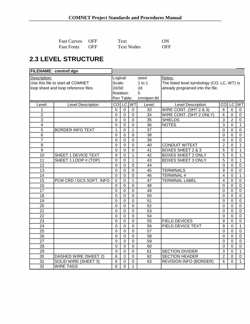
2.3 LEVEL STRUCTURE FILENAME: cmntref.dgn Description: Use this file to start all COMNET loop sheet and loop reference files.
Logical: Scale: 2d/3d: Rotation: Pen Table:
seed 1 to 1 2d 0 cmntpen.tbl
Notes: The listed level symbology (CO, LC, WT) is already programed into the file.
Level: Level Description CO LC WT Level: Level Description CO LC WT 1 0 0 0 33 WIRE CONT. (SHT 2 & 3) 6 0 0 2 0 0 0 34 WIRE CONT. (SHT 2 ONLY) 6 0 0 3 0 0 0 35 SHIELDS 3 2 0 4 0 0 0 36 NOTES 3 0 1 5 BORDER INFO TEXT 1 0 1 37 0 0 0 6 0 0 0 38 0 0 0 7 0 0 0 39 0 0 0 8 0 0 0 40 CONDUIT W/TEXT 2 0 1 9 0 0 0 41 BOXES SHEET 2 & 3 5 0 1 10 SHEET 1 DEVICE TEXT 9 0 1 42 BOXES SHEET 2 ONLY 5 0 1 11 SHEET 1 LOOP # (TOP) 0 0 1 43 BOXES SHEET 3 ONLY 5 0 1 12 0 0 0 44 0 0 0 13 0 0 0 45 TERMINALS 9 0 0 14 0 0 0 46 TERMINAL # 4 0 1 15 PCM CRD / DCS SOFT. INFO 0 0 1 47 TERMINAL LABEL 4 0 0 16 0 0 0 48 0 0 0 17 0 0 0 49 0 0 0 18 0 0 0 50 0 0 0 19 0 0 0 51 0 0 0 20 0 0 0 52 0 0 0 21 0 0 0 53 0 0 0 22 0 0 0 54 0 0 0 23 0 0 0 55 FIELD DEVICES 9 0 0 24 0 0 0 56 FIELD DEVICE TEXT 9 0 1 25 0 0 0 57 0 0 0 26 0 0 0 58 0 0 0 27 0 0 0 59 0 0 0 28 0 0 0 60 0 0 0 29 0 0 0 61 SECTION DIVIDER 3 0 1 30 DASHED WIRE (SHEET 2) 6 3 0 62 SECTION HEADER 2 0 0 31 SOLID WIRE (SHEET 3) 6 0 0 63 REVISION INFO (BORDER) 6 0 1 32 WIRE TAGS 6 0 1

COMNET Project Standards and Procedures Manual
FILENAME: cmntbord.dgn Description: Attach this border reference file to your loop sheet or loop reference file. DO NOT CHECK "SAVE FULL PATH".
Logical: Scale: 2d/3d: Rotation: Pen Table:
bord 1 to1 2d 0 cmntpen.tbl
Notes: Use this file by turning on or off the levels that apply to your loop sheet.
Level: Level Description CO LC WT Level: Level Description CO LC WT 1 SHEET 1 7 0 1 33 OF 13 7 0 1 2 SHEET 2 7 0 1 34 OF 14 7 0 1 3 SHEET 3 7 0 1 35 OF 15 7 0 1 4 SHEET 4 7 0 1 36 OF 16 7 0 1 5 SHEET 5 7 0 1 37 OF 17 7 0 1 6 SHEET 6 7 0 1 38 OF 18 7 0 1 7 SHEET 7 7 0 1 39 OF 19 7 0 1 8 SHEET 8 7 0 1 40 OF 20 7 0 1 9 SHEET 9 7 0 1 41 OF 21 7 0 1 10 SHEET 10 7 0 1 42 OF 22 7 0 1 11 SHEET 11 7 0 1 43 FIRST 3 ROWS 3 0 1 12 SHEET 12 7 0 1 44 ROW 4 3 0 1 13 SHEET 13 7 0 1 45 ROW 5 3 0 1 14 SHEET 14 7 0 1 46 ROW 6 3 0 1 15 SHEET 15 7 0 1 47 ROW 7 3 0 1 16 SHEET 16 7 0 1 48 ROW 8 3 0 1 17 SHEET 17 7 0 1 49 ROW 9 3 0 1 18 SHEET 18 7 0 1 50 ROW 10 3 0 1 19 SHEET 19 7 0 1 51 ROW 11 3 0 1 20 SHEET 20 7 0 1 52 ROW 12 3 0 1 21 SHEET 21 7 0 1 53 ROW 13 3 0 1 22 SHEET 22 7 0 1 54 ROW 14 3 0 1 23 OF 3 7 0 1 55 ROW 15 3 0 1 24 OF 4 7 0 1 56 INST. LOOP DEVICE SCHED 7 0 1 25 OF 5 7 0 1 57 INST. LOOP DIAGRAM 7 0 1 26 OF 6 7 0 1 58 INTERCONNECTION DIAG. 7 0 1 27 OF 7 7 0 1 59 0 0 0 28 OF 8 7 0 1 60 DATALINK GRID 6 0 0 29 OF 9 7 0 1 61 BORDER LINES 3 0 1 30 OF 10 7 0 1 62 BORDER TEXT 2 0 0 31 OF 11 7 0 1 63 0 0 0 32 OF 12 7 0 1

COMNET Project Standards and Procedures Manual
FILENAME: cmntdcs.dgn Description: Attach this DCS reference file to your loop sheet or loop reference file. DO NOT CHECK "SAVE FULL PATH."
Logical: Scale: 2d/3d: Rotation: Pen Table:
dcs 1 to 1 2d 0 cmntpen.tbl
Notes: Turn on or off the levels that apply to your loop sheet.
Level: Level Description CO LC WT Level: Level Description CO LC WT 1 DI 9 0 0 33 AI 9 0 0 2 DO 9 0 0 34 AO 9 0 0 3 AI 9 0 0 35 9 0 0 4 AO 9 0 0 36 9 0 0 5 9 0 0 37 9 0 0 6 9 0 0 38 9 0 0 7 9 0 0 39 POSITION 4 - "bit position" 9 0 0 8 9 0 0 40 POSITION 4 - "channel" 12 0 0 9 POSITION 1 - "bit position" 9 0 0 41 DI 9 0 0 10 POSITION 1 - "channel". 12 0 0 42 DO 9 0 0 11 DI 9 0 0 43 AI 9 0 0 12 DO 9 0 0 44 AO 9 0 0 13 AI 9 0 0 45 9 0 0 14 AO 9 0 0 46 9 0 0 15 9 0 0 47 9 0 0 16 9 0 0 48 9 0 0 17 9 0 0 49 POSITION 5 - "bit position" 9 0 0 18 9 0 0 50 POSITION 5 - "channel" 12 0 0 19 POSITION 2 - "bit position" 9 0 0 51 DI 9 0 0 20 POSITION 2 - "channel" 12 0 0 52 DO 9 0 0 21 DI 9 0 0 53 AI 9 0 0 22 DO 9 0 0 54 AO 9 0 0 23 AI 9 0 0 55 9 0 0 24 AO 9 0 0 56 9 0 0 25 9 0 0 57 9 0 0 26 9 0 0 58 9 0 0 27 9 0 0 59 POSITION 6 - "bit position" 9 0 0 28 9 0 0 60 POSITION 6 - "channel" 12 0 0 29 POSITION 3 - "bit position" 9 0 0 61 0 0 0 30 POSITION 3 - "channel". 12 0 0 62 0 0 0 31 DI 9 0 0 63 0 0 0 32 DO 9 0 0

COMNET Project Standards and Procedures Manual
2.4. WORKSPACE
A workspace is a custom MicroStation® environment or configuration. The workspace consists of three components – project, user interface, and preferences. The project configuration file (.pcf) is the only setting that has a COMNET standard. When first opening MicroStation®, the workspace settings box should appear as shown:
The project setting must say COMNET or the configuration settings will not take effect. If you do not see COMNET listed under Projects, you need to use Microsoft Explorer to copy R:\mwske\comnet\loops\proj_std\config\comnet.pcf to your personal hard drive at C:\Program Files\Bentley\Workspace\Projects\.

COMNET Project Standards and Procedures Manual
3. FILE MANAGEMENT AND TRACKING
3.1. FILE STORAGE
All of our loop reference and loop sheet files are to be stored on the R:\mwske\comnet\loops\project\ directory under the correct project folder name. The files are kept in this central location so that they can be backed up nightly by the network. Storing design files on your PC’s C:\ drive is a dangerous practice as you risk losing hundreds of hours of work with one crash of your hard drive.
3.2 FILE MODIFICATION
Loop reference and loop sheet files under the R:\mwske\comnet\loops\project directory may be modified only by those who have been assign to work on that particular project. Those who wish to view a file that is not in their project should check the “Open Design Files Read-Only” option on the MicroStation® File Manager. This will prevent accidental modification of information.
The design reference files and CADD configuration files found under the R:\mwske\comnet\loops\proj_std\ directory should only be modified by the CADD manager. This will promote uniformity in the content and appearance of our drawings.
3.3 FILE LOGS
It is the responsibility of the each CADD user to keep an updated Excel spreadsheet that logs each loop reference and loop sheet file for a particular project. The information of this file should include the filename, file description, date created, point names contained, and any other pertinent information. This file will be printed on 11 X 17 paper and used as a coversheet for files that are sent to the field. A blank template Excel spreadsheet for this purpose can be found in R:\mwske\comnet\loops\proj_std\manual\blnk_log.xls.
3.4 FILE BACKUP
In addition to the nightly backup done automatically by the network, the CADD manager shall periodically copy all the directories and files under R:\mwske\comnet\loops\ using an external hard drive.

COMNET Project Standards and Procedures Manual
4. GRAPHICS STANDARDS
4.1 TEXT
All text shall follow the standards given in section 2.2.5. In most cases, the justification should be set to CENTER-CENTER. In some cases, LEFT-CENTER should used when text needs to be aligned on the left side.
4.2 LINE WEIGHTS
The line weight scheme, which is automatically implemented in the level symbology, is designed to make drawing specific information stand out compared to less important information. This makes the drawings more attractive and easier to read. The more important information is assigned to weight-1 while less important is assigned weight-0.
4.3 CELL LIBRARIES
COMNET will use one cell library for all projects. The library, R:\mwske\comnet\loops\proj_std\cell\cmntcell.cel, is already attached to the COMNET seed file. The purpose of the library is to save time and promote uniformity in the appearance of the drawings. The library should be checked each time that an element for a drawing is needed and should be added to when a new element is created. Logical names and descriptions should be used for each cell to make it easier for others to find and use the cell.

COMNET Project Standards and Procedures Manual
5. DRAFTING PROCEDURES
5.1 REFERENCE FILES
Reference files are used when the same information needs to be used repeatedly. A reference file is used by attaching it to the file that you are currently working on. The levels of the reference file can then be turned on or off to reveal the information that is needed for your drawing.
5.1.1 Border Reference File
The border reference file, R:\mwske\comnet\loops\proj_std\refer\cmntbord.dgn, outlines the border and contains additional information such as Company logos, schedules, section headings, sheet #, of #, project name, and project number. See section 2.3. to see the level assignments for this file.
5.1.2 DCS Reference Files
There are currently 2 different DCS reference files. The first DCS file, R:\mwske\comnet\loops\proj_std\refer\cmntdcs.dgn contains the WPCD PCM card and DCS software information that appears on sheets 2 and 3. The second DSC file, R:\mwske\comnet\loops\proj_std\refer\cmntdcs2.dgn contains the Ovation PCM card and DCS software information that also appears on sheets 2 and 3. Be sure to use the appropriate DCS file. See Section 2.3 for the level assignments for the DCS file.
5.1.3 Loop Reference File
Each loop will have it’s own loop reference file. This file contains all the information that is specific to that loop. The COMNET seed file, R:\mwske\comnet\loops\proj_std\seed\cmntref.dgn, will be used to produce a .ref file.
5.2 SHEET FILES Sheet files are used strictly for generating plots and carry the extension .001,
.002, .003, etc. They are produced to display a single sheet by attaching the loop reference file, .ref, along with the reference files, cmntbord.dgn and cmntdcs.dgn.

COMNET Project Standards and Procedures Manual
6. DETAILED CADD PROCEDURES 6.1 Set Up The Comnet Workspace The Comnet workspace must be set up correctly for the procedure outlined herein to work. Use the Comnet CD provided by MWWD and follow each step exactly. See Section 2 – PROJECT SETUP for more detailed information.
From the Comnet CD, copy the “mwske” folder (with all sub folders) to the root of your local hard drive. When complete the directory tree should look like one The Comnet workspace must be set up correctly for the procedure outlined herein to work. Use the Comnet CD provided by MWWD CAD Department, and follow each step exactly.
1. From the Comnet CD, copy the “mwske” folder (with all sub folders) to the root of your local hard drive. When complete the directory tree should look like one shown in Figure 1. Do not insert or delete any folders in the path.
Note: The drive letter shown in Figure 1 is for example only. Use the drive letter that matches your particular drive set up.
Figure 1
2. Copy the Comnet project configuration file (comnet.pcf) from the Comnet CD in the folder \\mwske\comnet to C:\Program Files\Bentley\Workspace\Projects.

COMNET Project Standards and Procedures Manual
3. Copy the Comnet user configuration file (comnet.ucf) from the Comnet CD in the folder \\mwske\comnet to C:\Program Files\Bentley\Workspace\Users.
4. Determine which Device schedule (sheet 1) will be used for your loop project. Currently there are 2 different schedules approved for use with the Comnet project. The first type of schedule is the Comnet standard schedule and the second type is the DataLink schedule. Use the one schedule applicable to your loop design. Both schedules are accessed from the Comnet border file located at: R:\mwske\comnet\loops\proj_std\refer\cmntbord.dgn, by turning on or off the appropriate levels. The border file is attached to the Comnet seed file located at R:\mwske\comnet\loops\proj_std\seed\cmntref.dgn. See Section 2.3 for more information.
5. Determine which DCS file to use. Depending on the loop design use either the cmntdcs.dgn file, used for the WPCD system. You will need to use the cmntdcs2.dgn with the Ovation system. See Sections 5.1 and 5.2 for more information about DSC files. Attach the appropriate DSC file to the Comnet seed file located at R:\mwske\comnet\loops\proj_std\seed\cmntref.dgn. Use this seed file in the next step, Section 6.2 – Create the Main Loop Diagram.
6.2 Create the main loop diagram (*.ref) file1. Start Microstation Manager. Set up the Workspace as follows, set the User to
comnet, set the Project to comnet, and set the Interface to default as shown below in Figure 2
Figure 2

COMNET Project Standards and Procedures Manual
2. From the Microstation manager select File > New. The New dialog box will open. See Figure 3.
3. In the New dialog box, set the Seed File to: R:\mwske\comnet\loops\proj_std\seed\cmntref.dgn
Note: The drive letter shown above is for example only. Use the drive letter that matches your particular drive set up.
Figure 3
4. With the New dialog box, browse to the project folder where you will be storing your loop drawings and key in the loop name you are working with, e.g. s10f321.ref. If necessary, create a new folder, and then browse to it. Then click OK. A new design file will open with all the required borders, reference files and level libraries attached.
5. Create the loop drawing by placing Microstation text and elements in the appropriate views and on the proper levels.

COMNET Project Standards and Procedures Manual
6.3 Create the *.001 Sheet File
1. From the Microstation main window or Microstation Manager click File > New. The New dialog box will open. Make sure that the seed file is set to R:\mwske\comnet\loops\proj_std\seed\cmntseed.dgn. See Figure 4 below.
Note: The drive letter shown above is for example only. Use the drive letter that matches your particular drive set up.
Figure 4
Name the file: in the Files box, enter the correct loop filename with a “.001” extension. Click OK. A new design file will open.
2. Attach the main loop drawing (*.ref) to the new sheet file: Select File > Reference from the File menu. The References dialog box will open. Next select Tools > Attach, the Attach Reference dialog box will open. Browse to the *.ref file created in Section 2, then click OK. The Reference Attachment Settings dialog box will open. Set it up as shown below in Figure 5. Be sure to set the Nested Attachments box to Live Nesting and set the Depth to 1.

COMNET Project Standards and Procedures Manual
Figure 5
3. Set the Orientation to Coincident, and then click OK. The main loop drawing (*.ref) is now attached to the sheet file (*.001)
4. Turn on View 1, turn off all other views.
5. From the file Menu click File > Save. The Sheet file *.001 is now complete.
6. Each completed loop drawing must also be saved to PDF. Name the PDF files as follows: Using the loop s15y0511.001 as an example, name the PDF file s15y0511-001.pdf

COMNET Project Standards and Procedures Manual
6.4 Create the *.002 and *.003 Sheet Files
1. With the *.001 file open in Microstation, Click File > Save As. The Save As dialog box will open. See Figure 6.
Figure 6
2. In the Files box, enter the loop name with the extension “.002”. Make sure the Directories window is set to the correct project folder. Click OK.
3. A new design file will open that is an exact copy of the *.001 file.
4. Turn on View 2 and turn off all other views. Save Setting. The *.002 sheet file is now complete. Each completed loop drawing must also be saved to PDF format. Name the PDF file as follows: Using the loop s15y0511.002 as an example, name the PDF file s15y0511-002.pdf
5. With the *.002 file open in Microstation, click File > Save As. The Save As dialog box will open.
6. In the Files box, enter the loop name with the extension “.003”. Make sure the Directories window is set the correct project folder. Click OK.
7. Turn on View 3 and turn off all other views. Save setting. The *.003 sheet file is now complete. Each completed loop drawing must also be saved to PDF. Name the PDF files as follows: Using the loop s15y0511.003 as an example, name the PDF file s15y0511-003.pdf

COMNET Project Standards and Procedures Manual
6.5 Loop Drawings that require more than 3 sheets 1. Most loops need only 3 sheets which are created from Views in the “.ref” file for
the loop. In the “.ref” file for each loop, View 1 is the first (and usually only) sheet of the schedule, View 2 is the first sheet of the loop diagram, and View 3 is the first sheet of the interconnection diagram.
2. When more than 3 sheets are needed for a loop, add them by creating additional files with the same file name as the “.ref” file except using the extension “.rf1”, “.rf2” “.rf3” etc, and making Views 1, 2 and 3 of these files the second, third, and fourth sheets etc of the schedule, loop diagram, and interconnection diagram, respectively.
3. For example if Loop Number 16Y0201 needs 8 sheets to fully show it, there must be a “16Y0201.ref” file and two additional files. “.rf1” and “.rf2” as follows. In the “16Y0201.ref” file, View 1 is the first sheet of the schedule, View 2 is the first sheet of the loop diagram, and View 3 is the first sheet of the interconnection diagram. Similarly, in the “16Y0201.rf1” file, View 1 is the second sheet of the schedule, View 2 is the second sheet of the loop diagram, and View 3 is the second sheet of the interconnection diagram. And finally, in the “16Y0201.rf2” file, View 1 is the third sheet of the schedule, View 2 is the third sheet of the loop diagram, and View 3 is the third sheet of the interconnection diagram.
4. In cases where either the schedule, loop diagram, or interconnection diagram do not require additional sheets, leave the View blank in the corresponding file. In the above example, if there is no need for a third sheet to show the schedule, View 1 in the “16Y0201.rf2” file would be blank.
5. The sheet numbers for these must be consecutive and in the order of: schedule sheets first, loop diagram sheets second, and interconnection diagram sheets last. In the above case, Sheets 1 of 8 and 2 of 8 are the first and second sheets of the schedule, Sheets 3, 4, and 5 of 8 are the three loop diagram sheets, and Sheets 3, 4, and 5 of 8 are the three interconnection diagram sheets.

COMNET Project Standards and Procedures Manual
6.6 Revising Existing Loop Diagrams All Comnet Loop drawing revisions or changes are made to the *.ref file only. Do not make any changes to the sheet files (*.001, *.002, *.003). The sheet files are referenced to the *.ref file and therefore update automatically.
1. Open the Loop file (*.ref) to be revised. Edit the text that needs to be revised.
CAUTION: If placing new text be sure that the right level is active for the sheet you are revising, otherwise text will be inserted on the other sheets.
2. Place the revision number, date, description, and user name in the title block. Also update the revision number at the lower right corner of the title block.
3. Print the revised drawing. See Section 6.
6.7 Printing Loop Diagrams
1. All Comnet Loop Diagrams shall be printed from Bentley MicroStation with Bentley IPlot. Loop diagrams are printed directly from the sheet files only (*.001,*.002, *.003).
Do not print from the *.ref file.
2. Print all loop diagrams B size (11x17) using the Comnet standard pen table located in “R:\mwske\comnet\loops\proj_std\plot\comnet-ip.pen”. This is an Iplot pen table. The pen table is used to set all colors to black, sets the proper line weights, and prints the plot label (File name, date, and user name) on the left margin of the diagram.
3. Prints without the plot label in the left margin will be rejected.
6.7.1 SETTINGS FILE AND PEN TABLE
1. All Comnet Loop drawings will be printed by loading the Comnet setting file into IPlot. This setting file automatically sets the printer, form size, orientation, and pen table that have been previously configured to meet COMNET standards. The setting file is located at R:\mwske\comnet\loops\proj_std\plot\comnet-ip.set
2. A pen table is designed to customize the appearance of plots. The pen table, R:\mwske\comnet\loops\proj_std\plot\comnet-ip.pen, is configured to print Loop diagrams with the proper line weights and colors. The pen table is also used to print the plot label. The Comnet pen table, comnet-ip.pen is automatically loaded into Interplot be the Settings file.

COMNET Project Standards and Procedures Manual
6.7.2 PLOTTING PROCEDURE
1. With MicroStation open to the Loop diagram you want to plot. Fit the View. Place a fence around the border using the small red points at the lower left and upper right of the border.
2. From the Microstation File pull down menu, select File > Iplot. The IPLOT -Main dialog box will open as shown in figure 6.1.
Figure 6. 1
3. From the Iplot File pull down menu, select File > Select settings. The settings dialog box will open. Select the comnet-ip.set file from the list. The settings file will load all the required settings to plot Comnet Loop Diagrams to specification. Data point the Plot button. The plot is sent to the hp8550psw2k.

COMNET Project Standards and Procedures Manual
6.8 CAD Submittal Requirements for Loop Diagrams
1. Consultant must provide all CAD files (.ref and .001,002, 003) on a CD with the directory structure intact. See Section 1, Set up the Comnet Workspace. The CD should be set up as follows \mwske\Comnet\loops\project\Your project folder\. All CAD files, the main loop drawings (.ref) and the sheet files (.001, .002, and .003) should be in the \Your Project folder.
Note: Replace “Your project folder” with the name of the actual project name such as PS2.
2. Consultant must provide a PDF file for each loop drawing on the CD in the following location… \ mwske\Comnet\loops\project\Your project folder\PDF. See Sections 3 and 4 for PDF file naming conventions.
3. Consultant must provide B size (11x17) hard copies of all project loop diagrams. See Section 7 Printing Loop Drawings for more information.
4. Include a transmittal that lists each loop and the associated CAD file names and locations on the project CD. Put the transmittal in the project folder with the CAD files.