Commuter Rail Station Guidelines and StandardsMetra Commuter Rail Station Guidelines and Standards...
83
Commuter Rail Station Guidelines and Standards August 2007 These guidelines constitute internal recommendations only, are not now and have never meant to substitute for legal requirements. They provide guidance and do not mandate specific or absolute requirements or specifications for Metra rail station construction, alteration, or maintenance. In the case of any conflict between these Metra Commuter Rail Station Guidelines and Standards and the requirements mandated by the United States and/or Illinois statutes and regulations, Federal and State statutes and regulations shall control over these guidelines and standards, and compliance with Federal and State statutes and regulations shall conclusively constitute compliance with all Metra guidelines and standards.
Transcript of Commuter Rail Station Guidelines and StandardsMetra Commuter Rail Station Guidelines and Standards...
Commuter Rail Station Guidelines and Standards
August 2007
These guidelines constitute internal recommendations only, are not now and have never meant to substitute for legal requirements. They provide guidance and do not mandate specific or absolute requirements or specifications for Metra rail station construction, alteration, or maintenance. In the case of any conflict between these Metra Commuter Rail Station Guidelines and Standards and the requirements mandated by the United States and/or Illinois statutes and regulations, Federal and State statutes and regulations shall control over these guidelines and standards, and compliance with Federal and State statutes and regulations shall conclusively constitute compliance with all Metra guidelines and standards.

Metra Commuter Rail Station Guidelines and Standards Page i Rev. 8/29/2007
TABLE OF CONTENTS
I. INTRODUCTION ..................................................................................................................... 1 II. PLATFORMS .......................................................................................................................... 2
A. GENERAL........................................................................................................................... 2 B. LOCATION ......................................................................................................................... 2 C. SINGLE LINE TRACKS...................................................................................................... 2 D. MULTIPLE LINE TRACKS ................................................................................................. 2 E. CROSS TRACK BOARDING ............................................................................................. 2 F. AVOIDANCE OF CURVED PLATFORMS ......................................................................... 2 G. PLATFORM DIMENSIONS ................................................................................................ 3 H. PLATFORM LENGTH EXCEPTIONS ................................................................................ 4 I. ACCESS............................................................................................................................. 4 J. TACTILE STRIPS/DETECTABLE WARNINGS ................................................................. 8 K. TRACK CROSSINGS......................................................................................................... 8 L. AMENITIES ........................................................................................................................ 8 M. PASSENGER AMENITIES & SEATING ............................................................................ 9
III. STATION BUILDINGS.......................................................................................................... 11 A. NEW AND REPLACEMENT STATIONS ......................................................................... 11 B. EXISTING STATIONS...................................................................................................... 11 C. WAITING AREA GUIDELINES......................................................................................... 11 D. DEPOTS........................................................................................................................... 12 E. TICKET AGENT OFFICES............................................................................................... 14 F. ACCESSABILITY OF STATION BUILDINGS .................................................................. 15 G. VENDOR AREAS ............................................................................................................. 17 H. PUBLIC RESTROOMS .................................................................................................... 18 I. AUXILIARY SPACES ....................................................................................................... 19 J. INTERIOR REHABILITATION OF EXISTING BUILDINGS ............................................. 19 K. EXTERIOR REHABILITATION OF EXISTING BUILDINGS............................................ 19 L. NEW DEPOT CONSTRUCTION...................................................................................... 20 M. WARMING HOUSES........................................................................................................ 20 N. SHELTERS....................................................................................................................... 26 O. ELECTRIC TICKETHOUSES/HEADHOUSES ................................................................ 26 P. SECURITY CONSIDERATIONS...................................................................................... 33
IV. MECHANICAL SYSTEMS .................................................................................................... 36 A. HEATING, VENTILATION & AIR CONDITIONING (HVAC) ............................................ 36 B. PLUMBING & FIRE PROTECTION ................................................................................. 38 C. ELECTRICAL SYSTEMS ................................................................................................. 39 D. COMMUNICATIONS SYSTEMS...................................................................................... 43
V. LANDSCAPE DEVELOPMENT............................................................................................ 44 A. GENERAL......................................................................................................................... 44 B. EXISTING PLANT AND LANDSCAPE MATERIAL.......................................................... 44 C. SCREENING .................................................................................................................... 44 D. TREES.............................................................................................................................. 44 E. EMBANKMENTS.............................................................................................................. 44 F. BUSHES........................................................................................................................... 44 G. UNPAVED GROUND SURFACES .................................................................................. 44

Metra Commuter Rail Station Guidelines and Standards Page ii Rev. 8/29/2007
VI. MISCELLANEOUS ACCESSIBILITY GUIDELINES............................................................ 45 A. GENERAL......................................................................................................................... 45 B. SIGNAGE ......................................................................................................................... 45 C. TELEPHONES.................................................................................................................. 45
VII. MATERIAL & PERFORMANCE STANDARDS ................................................................... 46 A. PLATFORMS.................................................................................................................... 46 B. EXTERIOR WALLS .......................................................................................................... 47 C. ROOFING......................................................................................................................... 48 D. SOFFITS AND LOGGIAS................................................................................................. 49 E. INSULATION .................................................................................................................... 49 F. DOORS AND HARDWARE.............................................................................................. 50 G. WINDOWS........................................................................................................................ 51 H. INTERIOR PARTITIONS.................................................................................................. 54 I. FLOORING....................................................................................................................... 55 J. CEILINGS......................................................................................................................... 56 K. WAITING AREA SEATING............................................................................................... 57 L. WARMING HOUSES........................................................................................................ 58 M. ELECTRIC TICKETHOUSE/HEADHOUSE STANDARDS.............................................. 59 N. OTHER STATION STRUCTURES................................................................................... 61
VIII. PROJECT DELIVERABLES AND PLAN FORMAT............................................................. 62 A. PROJECT DELIVERABLES............................................................................................. 62 B. PLAN FORMAT ................................................................................................................ 62
IX. GLOSSARY .......................................................................................................................... 63 APPENDIX A. PROJECT CHECKLISTS ...................................................................................A-1 APPENDIX B. HISTORIC STATIONS ........................................................................................B-1 APPENDIX C. COST DATA........................................................................................................C-1

Metra Commuter Rail Station Guidelines and Standards Page iii Rev. 8/29/2007
TABLE OF FIGURES: FIGURE II - 1 MINIMUM STANDARD PLATFORM DIMENSIONS............................................... 3 FIGURE II - 2 MINIMUM INBOUND PLATFORM LENGTH........................................................... 4 FIGURE II - 3 MINIMUM OUTBOUND PLATFROM LENGTH....................................................... 4 FIGURE II - 4 RAMP CRITERIA..................................................................................................... 5 FIGURE II - 5 CURB RAMP CRITERIA ......................................................................................... 6 FIGURE II - 6 STAIR CRITERIA .................................................................................................... 6 FIGURE II - 7 ELEVATOR CRITERIA............................................................................................ 7 FIGURE III - 1 SQUARE FOOTAGE ALLOWANCE .................................................................... 11 FIGURE III - 2 PLATFORM STRUCTURES – DIESEL LINES .................................................... 12 FIGURE III - 3 PLATFORM STRUCTURES – ELECTRIC LINES ............................................... 12 FIGURE III - 4 DEPOT FUNCTIONAL RELATIONSHIP MATRIX ............................................... 13 FIGURE III - 5 TICKET OFFICE GUIDELINES............................................................................ 14 FIGURE III - 6 CIRCULATION PATH CRITERIA......................................................................... 16 FIGURE III - 7 DOOR AND HARDWARE CRITERIA .................................................................. 16 FIGURE III - 8 VENDOR GUIDELINES ....................................................................................... 18 FIGURE III - 9 TOILET GUIDELINES .......................................................................................... 18 FIGURE III - 10 DEPOT LAYOUTS.............................................................................................. 21 FIGURE III - 11 SINGLE WARMING HOUSE LOCATIONS........................................................ 22 FIGURE III - 12 DOUBLE WARMING HOUSE LOCATIONS ...................................................... 23 FIGURE III - 13 WARMING HOUSE SAMPLE LAYOUTS........................................................... 25 FIGURE III - 14 ELECTRIC TICKETHOUSE/HEADHOUSE FUNCTIONAL RELATIONSHIP
MATRIX.................................................................................................................................. 27 FIGURE III - 15 ELECTRIC TICKETHOUSE GUIDELINES MINIMUM AREA ............................ 28 FIGURE III - 16 HEADHOUSE STAIRWAY WIDTH .................................................................... 29 FIGURE III - 17 SAMPLE ELECTRIC TICKETHOUSE/HEADHOUSE LAYOUT AT A PED.
TUNNEL ................................................................................................................................. 30 FIGURE III - 18 SAMPLE ELECTRIC TICKETHOUSE/HEADHOUSE LAYOUT AT A ROADWAY
VIADUCT................................................................................................................................ 32 FIGURE IV - 1 AVERAGE ILLUMINANCE LEVELS – LUMEN METHOD................................... 41 FIGURE IV - 2 MINIMUM ILLUMINANCE LEVELS “POINT BY POINT” METHOD .................... 42 FIGURE IV - 3 LIGHTING ILLUMINANCE VALUES AND LIGHTING CONTROL CRITERIA .... 42 FIGURE IV - 4 LIGHTING ILLUMINANCE VALUES AND LIGHTING CONTROL CRITERIA .... 42 FIGURE VI - 1 SIGN CRITERIA................................................................................................... 45 FIGURE VI - 2 TELEPHONE CRITERIA...................................................................................... 45 FIGURE VII - 1 MINIMUM RABBET DEPTHS ............................................................................. 53

Metra Commuter Rail Station Guidelines and Standards Page 1 Rev. 8/29/2007
I. INTRODUCTION
The Metra Commuter Rail Station Design Guidelines and Standards establish guidelines and standards applicable to facility planning and design for Metra commuter rail stations in the six-county northeastern Illinois system. This Manual supercedes the Metra Commuter Rail Stations Guidelines and Standards Manual dated October 4, 1993. The guidelines and standards presented herein apply to new facilities as well as replacement and rehabilitation of existing stations. This manual is intended for use by Metra and by architectural and engineering consultants in the design and construction of station projects. This document though, is not intended to provide the level of detail required to develop construction contract documents, but rather to assist in the decision-making process. Strict adherence to these guidelines and standards may not be possible at a given station, but careful judgment should be exercised before deviating from them. Any deviation in these guidelines and standards by architectural or engineering consultants will require Metra’s approval. Objects of this Manual are:
• To provide safe, attractive, well designed, functional, and well maintained facilities. • To identify historic station buildings and provide guidelines for their restoration and reuse.
Community involvement in historic station restoration projects is recommended.
• To help provide efficient facilities by reducing their initial construction costs and minimizing their operation and maintenance costs.
• To establish quality control that will assist consultants in the planning and design of
stations and assist Metra in overseeing the adherence to the Standards in both the construction document phase and project submittal phase.
This Manual is intended to be used in conjunction with the most current version of the Metra CAD/D Manual which is available at the Stations & Parking Design Division web site at: www.metrarr.com/techservices. The website also contains the most recent standard details and other items required to complete a set of project deliverables. Any references to documents contained in this manual are intended to be the most recent version of the reference documents. Refer to Appendix B for Historic Station Guidelines.
Metra Commuter Rail Station Guidelines and Standards Page 2 Rev. 8/29/2007
II. PLATFORMS
A. GENERAL
This section discusses platform requirements at commuter rail stations. There are four main issues to be addressed in the station platform design: location, size, access, and amenities. The location addresses the relationship of the platform to the station buildings and the preference to avoid locating platforms on curves. The width and length of the platform is dictated by the location and the operational needs of Metra. Within this category, there are also issues about platform height and materials. Platform access is affected by the location of the station buildings, the type and size of the platform, and the location of the parking lots. Access may also be governed by various local codes, state codes and federal regulations. The regulations of the Americans with Disabilities Act (ADA), and the Federal Transit Administration ADA Key Station Assessment Sheets must be followed. METRA cannot stress enough the importance of adhering to or exceeding the accessibility requirements. The platform amenities include issues surrounding the type, size and location of telephone, benches, salt boxes, snow removal among others.
B. LOCATION
The platform designer should consider location of depots, shelters, parking areas, and points of public access. Where there are multiple access points to a platform, the designer should consider ways to distribute passengers among the cars. The platforms should be located to avoid interrupting the road traffic at nearby existing at-grade crossings. The end of the platform should be at least 100 feet from an at-grade crossing. Existing nonconforming platforms may remain in use, but should be replaced with standard platforms during station rehabilitation.
C. SINGLE LINE TRACKS
One platform shall be provided on the same side of the track as the station building. Where no station building exists, one platform shall be provided near public access and parking. For a new station, the preferred location for the platform and parking lot is on the inbound side of the track. This allows space for a second track at the station in the future.
D. MULTIPLE LINE TRACKS
On lines with two or more tracks, a platform shall be provided on the outside of each track. Island platforms shall be used at stations with three or more tracks. They are also used where site conditions and/or station configuration make outside platforms difficult to build on double track lines.
E. CROSS TRACK BOARDING
Boarding trains across active tracks is to be avoided.
F. AVOIDANCE OF CURVED PLATFORMS
To provide the conductor with a full view of passengers and not limit passenger view of oncoming trains, platforms should be located on tangent track whenever possible. Particular attention should be given to the elimination of platforms on curves. Where curved platforms are unavoidable, a limitation of 1º 40' of curvature or 1" in elevation of outer rail is recommended. Where curvature or elevation of outside rail exceeds this limit, every consideration should be given to platform relocation.
Metra Commuter Rail Station Guidelines and Standards Page 3 Rev. 8/29/2007
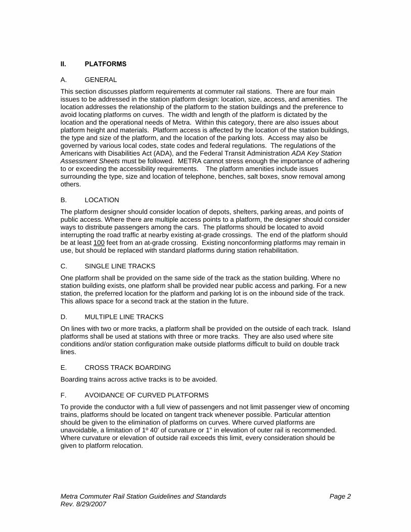
G. PLATFORM DIMENSIONS
The Metra rail system includes both low-level and high-level platforms. The diesel-powered lines: the BNSF, the UP North, Northwest and West lines, the Milwaukee District North and West lines, the North Central Service, the Heritage Corridor, the South West Service and the Rock Island District, have low-level platforms. The Metra Electric District which includes: the Main Line, South Chicago Branch, and the Blue Island Branch, and the Chicago, South Shore, and South Bend Railroad have high-level platforms. Dimension criteria are given in the Metra Standard Track Dimensions. Platform length is based on the current car length of 85 feet with an additional 40 foot braking margin. Actual platform lengths may vary due to site constraints. Platform length shall be based upon projected peak ridership and train operational requirements. Metra will provide current information on projected peak ridership for the station.
FIGURE II - 1 MINIMUM STANDARD PLATFORM DIMENSIONS
Type Standard Specification High Level (Electric District Only)
Height above rail: Min. Distance (tangent): Min. Distance (curve): Side Platform Width: Island Platform Width: Material: Support: Slope: Tactile warning: Other structure clearance (min.)
4'-3 1/2" 5'-7" from centerline of adjacent track to edge of platform. Add 1” additional horizontal offset for each 1º of track curvature. 10' Minimum. 15' Minimum. Armor Deck w/ integral tactile and non slip surface Reinforced concrete piers w/ steel or concrete cross beams. -¼”/foot* 2’ wide precast along trackside edge. 7’-6” from track centerline (Electric District) 8’-6” from track centerline (NICTD South Shore.)
Low Level Height above rail: Min. Distance (tangent): Min. Distance (curve): Side Platform Width: Island Platform Width: Material: Support: Slope: Tactile warning Other structure clearance (min.)
8" 5'-6" from centerline of adjacent track to edge of platform Add 1” additional horizontal offset for each 1º of track curvature. 10' Minimum. 15' Minimum if required. Asphalt Granular Subbase -¼”/foot* 2’ wide precast along trackside edge. 8’-6” from track centerline
* For side platforms, the slope should be down away from track, for center platforms there should be a crown along the center of the platform and the slopes should be down to platform edge.

Metra Commuter Rail Station Guidelines and Standards Page 4 Rev. 8/29/2007
FIGURE II - 2 MINIMUM INBOUND PLATFORM LENGTH
Projected Peak Train Boarding or Alighting
Diesel Lines Electric Lines
1 to 175 380 Lin. Ft. (5 cars) 465 Lin. Ft. (5 cars) 176 to 210 465 Lin. Ft. (6 cars) 550 Lin. Ft. (6 cars) 211 to 245 550 Lin. Ft. (7 cars) 635 Lin. Ft. (7 cars) 246 to 280 635 Lin. Ft. (8 cars) 635 Lin. Ft. * 281 to 315 720 Lin. Ft. (9 cars) 635 Lin. Ft. 316 to 350* 805 Lin. Ft. (10 cars) 635 Lin. Ft. 351 to 385* 890 Lin. Ft. (11 cars) 635 Lin. Ft. *Joint Metra/CSS & SB platforms are 720' long.
FIGURE II - 3 MINIMUM OUTBOUND PLATFROM LENGTH
Projected Peak Train Boarding or Alighting
Diesel Lines Electric Lines
1 to 105 380 Lin. Ft 380 Lin. Ft. 106 to 140 465 Lin. Ft 465 Lin. Ft. 141 to 175 550 Lin. Ft. 550 Lin. Ft. 176 to 210 635 Lin. Ft 635 Lin. Ft. 211 to 245 720 Lin. Ft 635 Lin. Ft. 246 to 280 805 Lin. Ft 635 Lin. Ft. 281 to 315 890 Lin. Ft 635 Lin. Ft. 315 to 350 890 Lin. Ft. 635 Lin. Ft. 351 to 385 890 Lin. Ft. 635 Lin. Ft.
H. PLATFORM LENGTH EXCEPTIONS
For Diesel Line Stations with either center or single platforms, the length of the platform shall be governed by the greater length for inbound or outbound platforms. Electric Lines stations typically have a single platform. The length of the platform shall be the greater length of either the inbound or the outbound platforms. Joint Metra/Chicago, South Shore & South Bend stations will have a 720 linear foot long platform because the CSS & SB operates eight car trains. Eleven car platform lengths shall only be used on the Union Pacific Northwest and West Lines. Future use of eleven-car platforms on other lines will be based on the purchase of new trains or change in station ridership. Where existing platforms lengths are shorter than required, the platform shall be lengthened, if possible. Specific line operations and individual site conditions such as: controlled crossings, station buildings, or stairways will determine the new length of the platform. If conditions require a platform length be shortened, excess platform shall be removed rather than abandoned.
I. ACCESS
1. GENERAL
Commuters tend to walk the shortest distance between the station access and the platform; sidewalks, stairs and ramps should be located to provide a clear path to direct commuters to and from the platform. Sidewalks shall be a minimum 6' wide. Where public access and platforms are at different elevations, ramps or stairs, or a combination of both, shall be provided. Where there is

Metra Commuter Rail Station Guidelines and Standards Page 5 Rev. 8/29/2007
a significant change in elevation between station access and platform, elevators or ramps shall be provided. The platforms should be designed to provide handicap access into train cars. On the diesel lines, a minimum of one car per trainset is equipped with a wheelchair lift. On the Electric District, the cars have a flip plate to bridge between the platform and the car.
2. RAMPS
Ramps are more desirable than stairways because of safety and ease of use by the elderly and individuals with disabilities. All new ramps shall conform to the ADA guidelines. Existing ramps not conforming to current ADA guidelines shall be reconstructed to meet those requirements. All handicap ramps that are not covered shall have a radiant heat snow melting system included in the design. Ramps are the preferred means of handicapped access because of the potential for vandalism and the overhead and maintenance costs of the alternatives. Ramps are required where there is a grade difference along the accessible route and the slope between those grades exceeds 1:20 (5%). Ramps shall be located to minimize the distance between the platform and the access point. Where the circulation path differs from that of the general public, provide appropriate signs to identify the accessible entrance and route.
FIGURE II - 4 RAMP CRITERIA
Maximum slope 1:12 (Design at 1:13 for Construction Tolerances) Minimum width 36"* Minimum landing Width equal to width of ramp
Length 60" clear 60" x 60" at any change of direction
Intermediate landings Intervals not to exceed 30" in rise Maximum ramp length 30' Ramp handrails required If rise exceeds 6"
If length exceeds 72" Continuous on both sides
Handrail height 36" Rail ends Extends 12" beyond top & bottom of ramp Parallel
to ground surface Handrail 1 1/4" to 1 1/2" in diameter
1 1/2" clearance from wall Maximum Cross Slope 1:50 (2%) Vertical Drop-offs Walls, guardrails or 2" high curb required. Guardrails 42" high, openings not greater than 4" * Minimum width ramps not to exceed 200’ in length without a 60”X60” passing area
3. ACCESSIBLE ROUTES AND CURB RAMPS
The route from station access points to station buildings and platforms shall be unobstructed and accessible to individuals with disabilities. Parking areas, walkways, ramps, and other ground or floor surface shall be firm, stable and slip resistant. If any walkway crosses or adjoins a vehicular way, and the walking surface is not separated by curbs, railings or other elements, the boundary between the areas shall be defined by a continuous detectable warning strip 36” wide, except adjacent to platform edges where they shall be 24" wide. If gratings are located in walking surfaces, grate openings shall be no greater than 1/2" wide, in one direction. The long dimension of the grate opening shall be placed so that it is perpendicular to the dominant direction of travel. Curb ramps shall be required whenever an accessible route crosses a curb.

Metra Commuter Rail Station Guidelines and Standards Page 6 Rev. 8/29/2007
FIGURE II - 5 CURB RAMP CRITERIA
Clear Width 36" Minimum Curb Sides Sides flared at 1:10 maximum slope where pedestrians walk across ramp.
Sides flared at 1:12 maximum slope Detectable Warnings
Provide visual contrast with adjoining surfaces. Material integral with walking surface. Truncated domes - reserved until further review by Access Board
4. STAIRS
Stairs may be provided in addition to ramps and shall conform to all applicable code requirements. New exterior stairs shall be of concrete or concrete and steel construction. Existing wood stairways used as secondary access to platforms may remain in use if in good condition, but should be considered for replacement. Stairways in excess of those required should be closed and demolished. New exterior stairways may be furnished with a canopy or other protective cover. Open risers are not permitted. Stairs that are provided in addition to ramps shall not only meet the design standards of this manual, but also shall conform to appropriate accessibility standards.
FIGURE II - 6 STAIR CRITERIA
Tread Depth 11" Minimum Risers Height 7" Maximum, Open risers not permitted. Perforated risers
allowed. Nosings Maximum Projection 1 1/2" Handrails Continuous on both sides Handrail Height 36" above stair nosing Handrail Extensions At top - 12" Beyond to riser with nosing parallel to floor
At bottom - Continue sloped for one stair depth plus 12" parallel to floor
Handrail 1 1/4" to 1 1/2" diameter 1 1/2" clearance from wall
Detectable Warning Not required until further action by Compliance Board.
5. ELEVATORS
Elevators shall be provided for platform access when other methods of providing handicap access are not feasible. Elevators should be located adjacent to the platform's main access point. All new elevators shall conform to the applicable requirements for accessibility for individuals with disabilities. Existing elevators may remain in use if they are in serviceable condition and meet the requirements for handicapped access. In general, hydraulic elevators are more suitable than geared or traction machines. Hydraulic operation eliminates the need for an overhead machine room and requires only a small enclosure to house the pumping equipment. A speed of 100 feet per minute is adequate for station facility elevators. The oil shall be heated to maintain the required operating temperature. To accommodate stretchers in emergencies, institutional-sized cabs are preferred. The elevator lobby should be designed to accommodate the movement of a stretcher. Elevator lobbies shall be heated. The lower floor position shall be the resting position of the elevator. All new elevators shall include remote monitoring capabilities compatible with Metra’s existing monitoring system by integrated display systems. Hardware and software shall be usable with the existing system.
Metra Commuter Rail Station Guidelines and Standards Page 7 Rev. 8/29/2007
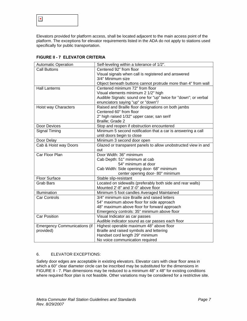
Elevators provided for platform access, shall be located adjacent to the main access point of the platform. The exceptions for elevator requirements listed in the ADA do not apply to stations used specifically for public transportation.
FIGURE II - 7 ELEVATOR CRITERIA
Automatic Operation Self-leveling within a tolerance of 1/2". Call Buttons Centered 92" from floor
Visual signals when call is registered and answered 3/4" Minimum size Object beneath buttons cannot protrude more than 4" from wall
Hall Lanterns Centered minimum 72" from floor Visual elements minimum 2 1/2" high Audible Signals: sound one for "up" twice for "down"; or verbal enunciators saying "up" or "down"/
Hoist way Characters Raised and Braille floor designations on both jambs Centered 60" from floor 2" high raised 1/32" upper case; san serif Braille; Grade 2
Door Devices Stop and reopen if obstruction encountered Signal Timing Minimum 5 second notification that a car is answering a call
until doors begin to close Door Delay Minimum 3 second door open Cab & Hoist way Doors Glazed or transparent panels to allow unobstructed view in and
out Car Floor Plan Door Width: 36" minimum
Cab Depth: 51" minimum at cab 54" minimum at door Cab Width: Side opening door- 68" minimum center opening door- 80" minimum
Floor Surface Stable slip-resistant Grab Bars Located on sidewalls (preferably both side and rear walls)
Mounted 2'-8" and 3'-0" above floor Illumination Minimum 5 foot candles Averaged Maintained Car Controls 3/4" minimum size Braille and raised letters
54" maximum above floor for side approach 48" maximum above floor for forward approach Emergency controls: 35" minimum above floor
Car Position Visual Indicator as car passes Audible indicator sound as car passes each floor
Emergency Communications (if provided)
Highest operable maximum 48" above floor Braille and raised symbols and lettering Handset cord length 29" minimum No voice communication required
6. ELEVATOR EXCEPTIONS:
Safety door edges are acceptable in existing elevators. Elevator cars with clear floor area in which a 60" clear diameter circle can be inscribed may be substituted for the dimensions in FIGURE II - 7. Plan dimensions may be reduced to a minimum 48" x 48" for existing conditions where required floor plan is not feasible. Other variations may be considered for a restrictive site.
Metra Commuter Rail Station Guidelines and Standards Page 8 Rev. 8/29/2007
J. TACTILE STRIPS/DETECTABLE WARNINGS
Platform edges bordering a drop-off and not protected by platform screens or guardrails shall have a detectable warning. The tactile strip shall be 24 inches wide running the full length of the platform edge drop-off.
K. TRACK CROSSINGS
1. AT-GRADE PEDESTRIAN CROSSINGS
Existing at-grade crossings in good condition may remain in use, but replacement of such crossings shall be included in any station improvement or rehabilitation program wherever practical. For maximum safety, warning signals shall be provided at all existing at-grade crossings. The number of at-grade crossings shall be based on the platform length. If one at-grade crossing is provided, the crossing should be located near the depot. If two at-grade crossings are provided, one crossing shall be located near the depot, and the other crossing shall be located at the one-third point. Platforms longer than 405 feet shall have two at-grade crossings. The maximum distance between grade crossings is 405 feet.
2. TRACK CROSSINGS
Where it is necessary for pedestrians to cross tracks, the crossing surface shall be level with the top of the rails. The pedestrian crossing must abut the outer rail edge and requires a maximum 2 1/2 inch gap on the inner edge of each rail to permit passage of train wheel flanges. Metra typically satisfies this requirement by use of a rubber rail seal. Where gap reduction is not practical, an above-grade or below-grade accessible crossing route shall be provided.
3. USE OF SIGNALIZED CROSSINGS
At locations where two or more tracks are crossed, traffic controls like flashing lights and bells must be provided. The use of gates at crosswalks is not allowed.
4. REGULATORY REQUIREMENTS
At-grade street and highway crossings must conform to the requirements contained in The Manual on Uniform Traffic Control Devices for Streets and Highways (MUTCD). All street or highway at-grade crossings are subject to the required US DOT approval process. Slopes to at-grade crossings shall comply with grades to curb ramps.
5. CROSSING CONSTRUCTION
Crossings shall be 12 or 16 feet wide depending on ridership and constructed of treated timber. The crossing shall extend from the face of one platform to the face of the opposite platform at the same elevation as the top of rail. The platform shall be depressed to the crossing at a rate that does not exceed 8” rise for 16’ of run.
6. CROSS TRACK BOARDING
Boarding trains across active tracks with commuters standing on an active track to board a train is to be avoided.
L. AMENITIES
1. TEMPORARY PLATFORMS
Temporary platforms shall be used whenever construction work at station facilities or tracks prevents use of normal platforms. Temporary platforms shall be constructed of durable materials, such as pressure-treated fire-resistant lumber and bituminous concrete, with non-slip surfacing. Temporary directional and informational signage shall be provided, indicating locations and use of
Metra Commuter Rail Station Guidelines and Standards Page 9 Rev. 8/29/2007
temporary platforms. All temporary platforms and signage shall be removed when permanent platforms are returned to service.
2. PLATFORM SNOW REMOVAL
For passenger safety, snow shall be removed from the platforms whenever the accumulation exceeds one inch. Space should be allocated during site planning for snow pile areas. Snow piles should be located away from the track side of the platform and so that when melting occurs, the water will not flow onto the platform and pond or freeze. Platforms are heavily salted and shall be designed accordingly. Gravel ramps shall be provided for vehicular access at both ends of the platform. This is to allow snow plow trucks and electrician’s bucket trucks to access the platforms and expedite the snow removal process and platform lighting maintenance.
3. SALT BOX LOCATIONS
For platforms under 805’ in length, one salt box shall be located at a strategic location on each platform. For platforms 805’ or longer, 2 salt boxes per platform shall be used and placed at the approximate quarter points from the ends of the platforms. Except on center platforms, salt boxes shall be located behind the outside platform edge to allow for snow plowing and passenger movement. Salt boxes shall be placed on a 4' deep x 8' long x 5" thick concrete pad. On center platforms, salt boxes shall be placed along the center-line of the center of platform.
4. PLATFORM FENCING AND GUARDRAILS
Platform fencing and guardrails should be located along the back side of the platform at locations where there is a vertical drop greater than 18” with less than a 4:1 slope adjacent to the back platform edge, where active freight tracks are located behind the platform, , for crowd control, or at any other location where it is deemed necessary. Fencing should be located a minimum of 8’-6” from the nearest track center-line.
5. INTERTRACK FENCING
Intertrack fencing shall be located between tracks at multiple track stations to discourage unauthorized crossing of the tracks. This fencing shall consist of a 3 ½’ high chain link fence with a 6” gap at the bottom of the fence. Intertrack fencing shall extend a minimum of 50 feet beyond the platform.
M. PASSENGER AMENITIES & SEATING
1. GENERAL
Platform amenities are those fixtures, furnishings, and equipment which provide convenience to riders. Each should be located behind the platform to provide convenience without interfering with normal passenger flow. The specific types and quantities of amenities will vary from station to station.
2. TELEPHONES
The Station/Platform design shall include conduits for the placement of a pay telephone adjacent to the depot. For security, underpasses and overpasses are undesirable locations for public telephones; an exception may be made when an underpass or overpass is incorporated into a station concourse and is under the visual control of the ticket agent.
3. TELEPHONE EQUIPMENT AND MOUNTING
Interior public telephones should be avoided. If an interior public telephone is provided, it shall be equipped with a TDD shelf and mounted at the appropriate ADA height. Exterior public

Metra Commuter Rail Station Guidelines and Standards Page 10 Rev. 8/29/2007
telephones shall not be mounted to building walls, to canopy framing or to other structural members. Post-mounting systems shall be used for all exterior telephone installations. Telephone equipment and mounting shall meet accessibility guidelines.
4. NEWSPAPER VENDING MACHINES
The station shall be designed to provide an area where newspaper vending machines can be clustered. METRA prefers that they be located between the primary access points and the inbound platform but not on the platform itself. The location(s) chosen shall not create bottlenecks at station entrances, stairways, or other access points. They should be securely anchored to the ground; using chains to anchor the machines to railings is unacceptable.
5. OTHER VENDING MACHINES
Food, beverage, or novelty vending machines are not permitted on platforms.
6. TRASH CONTAINERS
Trash containers shall be adjacent to both the inbound and the outbound platforms near the station building. They shall also be located at access points such as crosswalks and stairs that service both the inbound and outbound platforms. Trash containers shall be placed for ease of use and not hinder pedestrian movement on the platform. The containers shall be of either: metal, reinforced fiberglass, wood, or concrete; whichever is appropriate for the station design. Removable liners shall be included because they facilitate emptying trash container. Containers shall be clearly labeled, and securely anchored. Chaining of containers shall not be considered as secure anchorage. Trash containers shall have permanent lids with spring-loaded access doors, to minimize bee and insect problems at containers. Trash containers shall be placed so that they cannot be used to climb on to canopies, roofs of shelters, or other high areas. Concrete pads constructed for benches should be extended to accommodate trash containers.
7. WINDBREAKS
Windbreaks shall be provided at the rear of platforms where it is not practical to install other shelters or structures. Windbreaks are generally installed either at stations that are fairly open to the elements or at stations where ridership does not justify a more elaborate structure. Windbreaks should be designed not to trap wind-borne debris.
8. SEATING
Anchored benches shall be provided on both inbound and outbound platforms. Seating for approximately 15% of projected peak-train boardings is recommended. Seating shall be distributed along the platform and in station buildings. Seating shall also be provided at the designated passenger pickup areas. The benches and seating units shall have individual seats, separated by dividers. They shall be constructed in a durable, weather-resistant, and vandal-resistant manner. They shall be anchored in a secure, tamper-resistant manner to bench pads which are to be located behind the platform. For island platforms, benches shall be placed at the center of the platform. For side platforms, benches must not be placed on the platform, but shall be placed on a concrete pad behind the platform.
9. ADVERTISING DISPLAYS
Advertising displays are an important source of revenue for Metra. Advertising displays may be incorporated into the walls of canopies, windbreaks, or as freestanding signboards. Display board sizes should be coordinated with standard poster sizes. The size and location will be subject to review by Metra and local ordinances. In no case shall the advertising display be placed on the platform in such a way that it will interfere with the flow of passengers.
Metra Commuter Rail Station Guidelines and Standards Page 11 Rev. 8/29/2007
III. STATION BUILDINGS
There are two basic types of station buildings: existing and new. Both new and existing station buildings must comply with the ADA and the accessibility standards and both will get the same amenities.
A. NEW AND REPLACEMENT STATIONS
Each station design will depend upon other factors in addition to passenger volume. Unusual site conditions or community involvement in design are elements that may cause variations in the planning guidelines for new and replacement stations. Any significant deviations to the planning guidelines should be discussed with Metra prior to design and implementation. Along with Waiting Area space planning guidelines, Section III contains guidelines for the Ticket Agents, Vendors, Toilets and Electric tickethouses.
B. EXISTING STATIONS
When evaluating existing stations, existing areas and amenities shall be compared to the guidelines to identify any excesses or shortages. When renovating a station, the goal is to bring existing stations into close compliance with the guidelines. The cost to do this must be weighed against the benefits derived from increased ridership, increased revenue, and/or decreased maintenance. Existing structures may be supplemented with an additional structure to bring the overall station facility closer to guidelines; for example, adding a warming house or shelter. Existing depots in good condition with excess waiting area space according to the guidelines, may consider other potential uses for the excess space such as providing vendor area, etc.
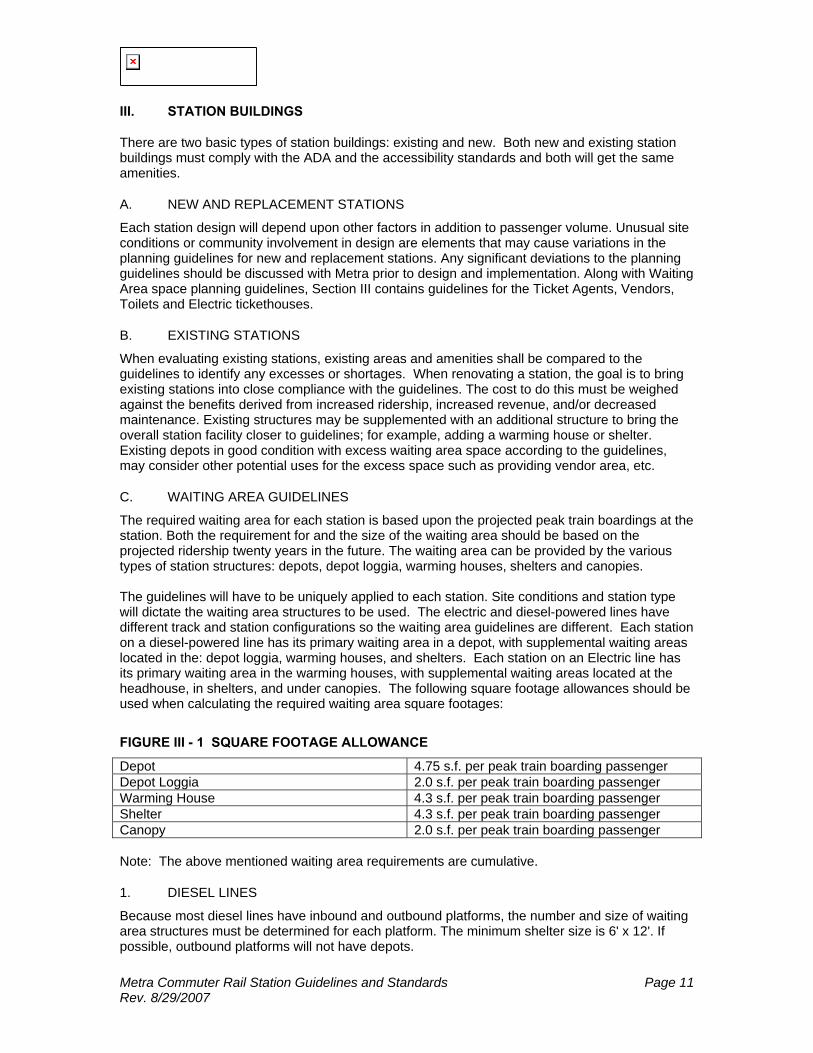
C. WAITING AREA GUIDELINES
The required waiting area for each station is based upon the projected peak train boardings at the station. Both the requirement for and the size of the waiting area should be based on the projected ridership twenty years in the future. The waiting area can be provided by the various types of station structures: depots, depot loggia, warming houses, shelters and canopies. The guidelines will have to be uniquely applied to each station. Site conditions and station type will dictate the waiting area structures to be used. The electric and diesel-powered lines have different track and station configurations so the waiting area guidelines are different. Each station on a diesel-powered line has its primary waiting area in a depot, with supplemental waiting areas located in the: depot loggia, warming houses, and shelters. Each station on an Electric line has its primary waiting area in the warming houses, with supplemental waiting areas located at the headhouse, in shelters, and under canopies. The following square footage allowances should be used when calculating the required waiting area square footages:
FIGURE III - 1 SQUARE FOOTAGE ALLOWANCE
Depot 4.75 s.f. per peak train boarding passenger Depot Loggia 2.0 s.f. per peak train boarding passenger Warming House 4.3 s.f. per peak train boarding passenger Shelter 4.3 s.f. per peak train boarding passenger Canopy 2.0 s.f. per peak train boarding passenger Note: The above mentioned waiting area requirements are cumulative.
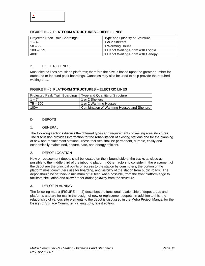
1. DIESEL LINES
Because most diesel lines have inbound and outbound platforms, the number and size of waiting area structures must be determined for each platform. The minimum shelter size is 6' x 12'. If possible, outbound platforms will not have depots.
Metra Commuter Rail Station Guidelines and Standards Page 12 Rev. 8/29/2007
FIGURE III - 2 PLATFORM STRUCTURES – DIESEL LINES
Projected Peak Train Boardings Type and Quantity of Structure 1 – 49 1 or 2 Shelters 50 – 99 1 Warming House 100 – 399 1 Depot Waiting Room with Loggia 400+ 1 Depot Waiting Room with Canopy
2. ELECTRIC LINES
Most electric lines are island platforms; therefore the size is based upon the greater number for outbound or inbound peak boardings. Canopies may also be used to help provide the required waiting area.
FIGURE III - 3 PLATFORM STRUCTURES – ELECTRIC LINES
Projected Peak Train Boardings Type and Quantity of Structure 1 – 74 1 or 2 Shelters 75 – 100 1 or 2 Warming Houses 100+ Combination of Warming Houses and Shelters
D. DEPOTS
1. GENERAL
The following sections discuss the different types and requirements of waiting area structures. The discussion provides information for the rehabilitation of existing stations and for the planning of new and replacement stations. These facilities shall be permanent, durable, easily and economically maintained, secure, safe, and energy efficient.
2. DEPOT LOCATION
New or replacement depots shall be located on the inbound side of the tracks as close as possible to the middle third of the inbound platform. Other factors to consider in the placement of the depot are the principal points of access to the station by commuters, the portion of the platform most commuters use for boarding, and visibility of the station from public roads. The depot should be set back a minimum of 20 feet, when possible, from the front platform edge to facilitate circulation and allow proper drainage away from the structure.
3. DEPOT PLANNING
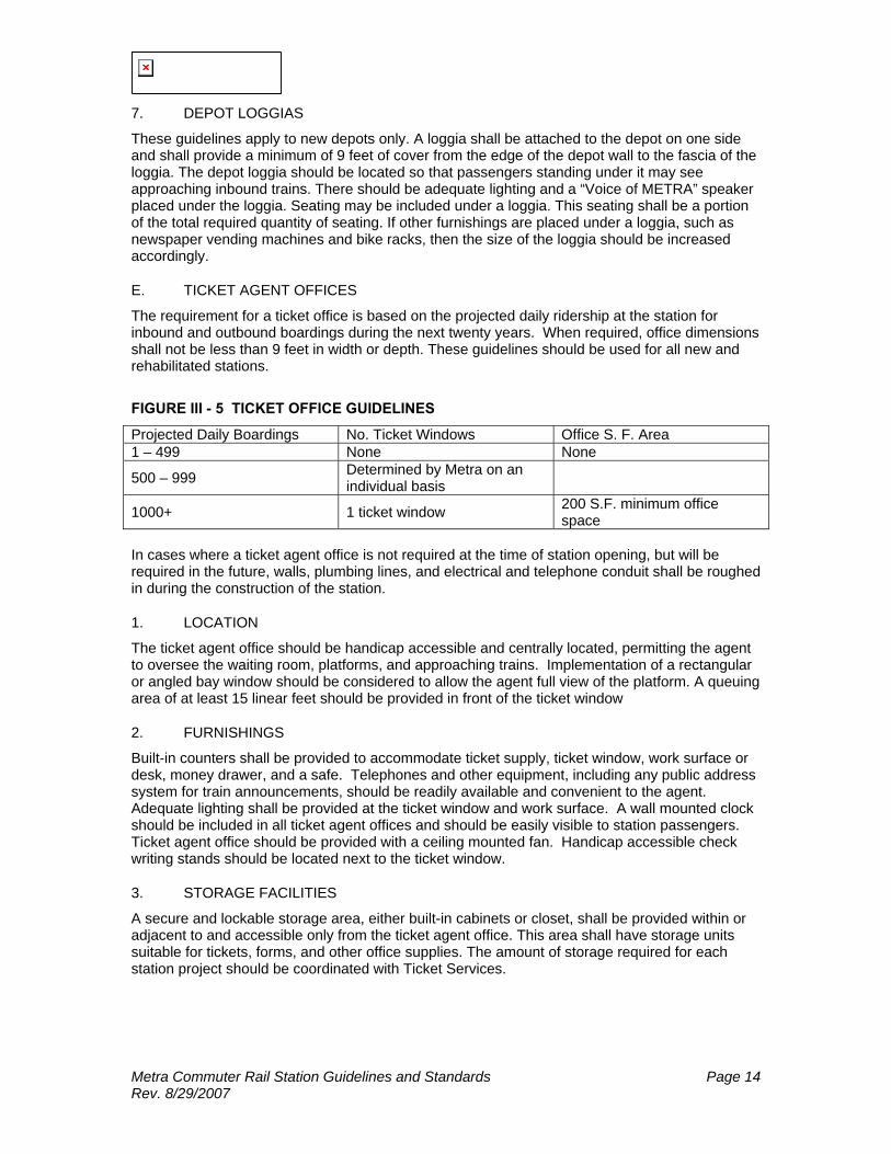
The following matrix (FIGURE III - 4) describes the functional relationship of depot areas and platforms and are for use in the design of new or replacement depots. In addition to this, the relationship of various site elements to the depot is discussed in the Metra Project Manual for the Design of Surface Commuter Parking Lots, latest edition.
Metra Commuter Rail Station Guidelines and Standards Page 13 Rev. 8/29/2007
FIGURE III - 4 DEPOT FUNCTIONAL RELATIONSHIP MATRIX
KEY: ♦ PHYSICAL ADJACENCY REQUIRED + CLOSE ADJACENCY DESIRABLE 0 NO ADJACENCY/SEPARATION NECESSARY - PHYSICAL SEPARATION DESIRABLE NOTE: NOT ALL AREAS AT ALL DEPOTS
4. ENTRY/EXIT DOORS
The design of the waiting area in the depot should incorporate the location of glazing for passenger visibility. Trains and buses should be visible from the waiting room. A mirror may be used to aid commuters in viewing approaching trains.
5. GLAZING
The bottom of the glazing element shall be a minimum of 24" above finished floor. The maximum height of the glazing element shall be between 6'- 8" and 7' - 2" above finished floor.
6. VESTIBULES/AFTER HOUR WAITING
New depots shall have a vestibule located between the platform and the main entrance to the waiting room. The vestibule should be accessible 24 hours a day. Access to the depot shall be controlled with either a lockable pull down security grill or a second entrance doorway between the vestibule and waiting room. Seating shall also be provided along the wall in the vestibule for use of non-peak commuters.
Metra Commuter Rail Station Guidelines and Standards Page 14 Rev. 8/29/2007
7. DEPOT LOGGIAS
These guidelines apply to new depots only. A loggia shall be attached to the depot on one side and shall provide a minimum of 9 feet of cover from the edge of the depot wall to the fascia of the loggia. The depot loggia should be located so that passengers standing under it may see approaching inbound trains. There should be adequate lighting and a “Voice of METRA” speaker placed under the loggia. Seating may be included under a loggia. This seating shall be a portion of the total required quantity of seating. If other furnishings are placed under a loggia, such as newspaper vending machines and bike racks, then the size of the loggia should be increased accordingly.
E. TICKET AGENT OFFICES
The requirement for a ticket office is based on the projected daily ridership at the station for inbound and outbound boardings during the next twenty years. When required, office dimensions shall not be less than 9 feet in width or depth. These guidelines should be used for all new and rehabilitated stations.
FIGURE III - 5 TICKET OFFICE GUIDELINES
Projected Daily Boardings No. Ticket Windows Office S. F. Area 1 – 499 None None
500 – 999 Determined by Metra on an individual basis
1000+ 1 ticket window 200 S.F. minimum office space
In cases where a ticket agent office is not required at the time of station opening, but will be required in the future, walls, plumbing lines, and electrical and telephone conduit shall be roughed in during the construction of the station.
1. LOCATION
The ticket agent office should be handicap accessible and centrally located, permitting the agent to oversee the waiting room, platforms, and approaching trains. Implementation of a rectangular or angled bay window should be considered to allow the agent full view of the platform. A queuing area of at least 15 linear feet should be provided in front of the ticket window
2. FURNISHINGS
Built-in counters shall be provided to accommodate ticket supply, ticket window, work surface or desk, money drawer, and a safe. Telephones and other equipment, including any public address system for train announcements, should be readily available and convenient to the agent. Adequate lighting shall be provided at the ticket window and work surface. A wall mounted clock should be included in all ticket agent offices and should be easily visible to station passengers. Ticket agent office should be provided with a ceiling mounted fan. Handicap accessible check writing stands should be located next to the ticket window.
3. STORAGE FACILITIES
A secure and lockable storage area, either built-in cabinets or closet, shall be provided within or adjacent to and accessible only from the ticket agent office. This area shall have storage units suitable for tickets, forms, and other office supplies. The amount of storage required for each station project should be coordinated with Ticket Services.
Metra Commuter Rail Station Guidelines and Standards Page 15 Rev. 8/29/2007
4. AGENT'S TOILET
Space allocated for the ticket agent's toilet shall be 80 square feet. To maintain the security of the ticket office, a single-person handicap accessible toilet room shall be provided adjacent to and accessible only from the agent's office, eliminating the need for the agent to leave the ticket office area. This toilet room shall be for the exclusive use of the agent. Fixtures and accessories shall include a water closet, grab bars, lavatory, wall-mounted mirror and shelf, toilet paper roll holder or dispenser, soap dispenser, paper towel dispenser and waste receptacle. A wall-mounted light fixture shall be installed over the mirror. The toilet room shall be ventilated in conformance with all applicable code requirements.
F. ACCESSABILITY OF STATION BUILDINGS
1. RAMPS
Ramp access is required at station buildings where there is a grade difference. Ramps shall be located where practical, at the entrance to the station building used by the general public. Where the ramped entrance to the station building is in a different location than the general public, appropriate signage shall be provided.
2. STAIRS
Exterior stairs to station buildings, as well as interior stairs within station buildings, shall comply with the appropriate accessibility standards.
3. ELEVATORS
Elevators within station buildings shall comply with the appropriate accessibility standards.
4. CIRCULATION PATHS
Accessible entrances and accessible routes both inside and outside station buildings should coincide with the circulation paths for the general public, wherever possible. At least one entrance to each station building shall comply with minimum accessibility requirements. FIGURE III - 6 identifies minimum requirements of an accessible path.
5. ENTRY VESTIBULES
Station buildings which have entry vestibules with two separate sets of doors must have the required minimum clear floor space between sets of doors. The minimum clear distance from the inside face of the first door to the edge of the swing of the second door is 48". At no time shall the vestibule be less than 7'-0" deep.
6. DOORS/HARDWARE
All doors at required entrances on accessible routes or into accessible spaces shall comply with the appropriate accessibility standards. Pivoted (balanced) swing doors are standard for all exterior uses. Hinged single leaf doors are standard for interior use. Extra door size is required for a pivoted door to meet the 32" clear width minimum. FIGURE III - 7 identifies minimum requirements of accessible doors and hardware. Revolving doors shall not be the only means of passage. Maneuvering clearances for the various approaches shall follow the requirements set forth in the American’s with Disabilities Act.
7. TICKET WINDOWS
Standard ticket counters are within the accessible reach ranges. An auxiliary transaction counter for check writing, 10” wide by 36" long and 34" maximum height, shall be provided near the main counter. The ticket window and the auxiliary counter shall be located on an accessible route and provide the minimum clear floor space and maneuvering clearances.
Metra Commuter Rail Station Guidelines and Standards Page 16 Rev. 8/29/2007
FIGURE III - 6 CIRCULATION PATH CRITERIA
Clear Width 36" Minimum Turn Widths 36" for 900 turn with no additional turn for 48" Passing Spaces required at 200' intervals if route is less than 60" wide
60" x 60" floor space
Headroom Clearance
80" minimum
Running Slope 1:20 (5%) Maximum Cross Slope 1:50 (2%) Maximum Level Changes Up to 1/4" - no edge treatment required
1/4" to 1/2" - beveled edge with slope no greater than 1:2 Greater than 1/2" - requires ramp, elevator, or lift
Floor Surfaces Firm, stable, slip-resistant Protruding Objects
Objects projecting below 27" above finished floor may protrude any amount Object with leading edges between 27" and 80" above finished floor shall protrude no more than 4" into walls or corridors Free Standing objects on posts may overhang 12" maximum from 27" to 80" above floor
Clear Floor Space
Single wheelchair - 30" x 48"
Alcove Clearances
36" minimum width for forward approach to alcove deeper than 24" 60" minimum width for parallel approach
Reach Ranges 15" Minimum height forward approach 48" Maximum height forward approach 9" Minimum side reach parallel approach 54" Maximum side reach parallel approach
Egress Same number of exits as for life safety regulations
FIGURE III - 7 DOOR AND HARDWARE CRITERIA
Clear Opening 32" minimum for standard opening depths 36" minimum for opening depths over 24" 1/2" Maximum height Beveled with scope no greater than 1:2
Thresholds Note: There are to be no thresholds on or adjacent to Metra Electric platforms.
Existing thresholds at 3/4" height with beveled edges may remain
Handles Pulls Latches and Locks Lever-operated push mechanisms & U-shaped handles acceptable Hand activated hardware mounted Mounted 30" to 44" above floor
Door Closers Adjustable sweep takes 3 second for door to travel from 70° open to 3" from latch
Door Force 8.5 lbf maximum for exterior hinged doors 5 lbf maximum for interior hinged doors sliding or folding doors Fire doors by applicable code
Door Side Clearance 18" clear wall area on latch side
Tactile Warnings Textured contact surfaces on handles for doors to hazardous areas

Metra Commuter Rail Station Guidelines and Standards Page 17 Rev. 8/29/2007
8. TICKET VENDING (METRA ELECTRIC DISTRICT ONLY)
Ticket vending machines shall be located on an accessible route. If provided, at least one self serve fare collecting device per bank shall be accessible. Coin or card slots and controls necessary for operation shall be at accessible heights and reach ranges.
9. TOILETS
Public toilets, if provided, shall be located on an accessible route. Each toilet room requires an unobstructed turning space of 60" diameter, or a T-shaped space 60" square with 36" legs. At least one of each fixture type located in the toilet room shall be accessible. Refer to ANSI - 117.1 and ADA for fixture accessibility requirements. The door to the toilet room shall not swing into any clear floor space required for the fixtures. The ticket agent's toilet room is required to be handicap adaptable.
10. CLOCKS
Where clocks are provided for the general public, the clock face shall be uncluttered and clearly visible. Elements shall contrast with the background, either light-on-dark or dark-on-light. Where overhead clocks are provided, the numerals and or digits shall be a minimum of 3" in height.
11. FURNISHINGS
Built-in counters or tables shall be 28" minimum and 34" maximum above finished floor. The furnishings in the ticket agent office need not be made accessible at the time of construction, but the space provided must be planned with proper maneuvering clearances. Fixed counters or tables that are provided in the ticket agent office should meet accessibility requirements to avoid modification in the future.
12. SEATING
New and rehabilitated depot waiting rooms should provide seating for 15 percent of the projected peak train boardings. The seating shall be distributed among the station buildings, with the majority of the seating in the depot. New seating in waiting rooms shall be benches. Seating should be located along walls wherever possible and not be located in the main aisle of the waiting room. If in good condition, benches in existing waiting rooms should be retained. Existing single seat benches made of plastic shall be replaced. The benches and seating units should have individual seats, separated by dividers. They shall be constructed in a durable, weather-resistant, and vandal-resistant manner. They shall be anchored in a secure, tamper-resistant manner to the floor or wall.
13. DOORS
The following guidelines apply to new and replacement depots only. A minimum of two entry/exit doors shall be provided in all waiting rooms. One of those doors shall be provided on the platform side of the depot and one on the side facing the station's primary access point. The location of these doors must also meet the minimum distance required by applicable codes for emergency exiting requirements. For stations with over 130 projected peak train boardings, a minimum of one door leaf shall be added to the first two doors for each additional 65 peak train boardings. A minimum of two thirds of all waiting room entry/exit doors shall directly access the platform when three or more doors are required. All new entry doors shall be manufactured and installed in accordance with the design and material standards in Section VII of this Manual.
G. VENDOR AREAS
Vendor areas are based on projected peak daily ridership at a station for inbound and outbound boardings during the next twenty years. Vendor areas are based on a coffee/food vendor's requirements. Though this vendor is the most common at stations, other vendor types such as automatic teller machines (ATM's), newsstands, taxi services, dry cleaners and video rentals are

Metra Commuter Rail Station Guidelines and Standards Page 18 Rev. 8/29/2007
also possible. Laundromats or convenient food stores may be considered with local community input. The area required for each of these different vendors should be analyzed on an individual basis considering such factors as equipment and circulation requirements. If a vendor is not under contract for the space at the time of depot design, utilities shall be roughed in. This space shall be utilized as additional waiting area without benches. All unused space in existing depots should be considered vendor area regardless of the number of riders at the station.
FIGURE III - 8 VENDOR GUIDELINES
Projected Daily Boardings Vendor Area Required
1 – 499 Vendor requirements to be reviewed by Metra
500 – 999 100 S.F. 1000 - 1999 150 S.F. 2000+ 200 S.F.
1. LOCATION
Vendor areas should be located adjacent to the waiting area but should not create circulation conflicts at the entry and should not block or restrict the view of inbound trains from the waiting room. Very small vendors may be located in the waiting room and allowed to set up a small table, provided there is sufficient waiting area per the space guidelines.
2. FURNISHINGS
Metra may provide the vendor with shell space which shall be finished by the vendor. Shell space shall be defined as an area within the depot with unfinished walls, an entry door, serving window with security gate, storage closet, electricity, and heat. Plumbing and sewer lines will be stubbed out along one wall. The vendor shall provide all air conditioning, finishes, and furnishings.
H. PUBLIC RESTROOMS
1. AREA
Due to security problems, maintenance expenses, and the short waiting period for commuters, public restrooms will generally be located in downtown terminal stations and at intermodal transportation centers. Newly constructed or rehabilitated outlying stations with depots of less than 3,000 net square feet will not have public restrooms. Restrooms may be provided at an outlying station if that station is locally maintained. If public restrooms are provided there must be both a men’s and women’s restrooms as unisex restrooms are not allowed under Illinois Plumbing Code. If a municipality wishes to maintain public restrooms, then the requirements shall be based on projected daily boardings at a station for inbound and outbound boardings during the next twenty years.
FIGURE III - 9 TOILET GUIDELINES
Projected Daily Boardings Toilet Requirements 1 - 600 Men - 1 Toilet & 1 Lavatory Women - 1 Toilet & 1 Lavatory
600+ Men - 1 Toilet, 1 Urinal & 1 Lavatory Women - 2 Toilet & 1 Lavatory
Where local codes require public restrooms at the depot, the number and type of fixtures at a station should be based on the minimum code requirements.
Metra Commuter Rail Station Guidelines and Standards Page 19 Rev. 8/29/2007
2. LOCATION
Public restrooms shall be located adjacent to the waiting room, but the restroom doors should not open directly into the main waiting room.
3. FIXTURES & ACCESSORIES
Public restrooms should have fixtures and accessories similar to the ticket agent's toilet given in Section III.E.4. Fixture and material finish selection shall consider the prevention of vandalism.
I. AUXILIARY SPACES
4. JANITOR'S CLOSET
A room for janitorial functions shall be provided in all depots and in warming houses when there is no depot present at a station location. This closet shall have a service sink or mop receptor with hot and cold water and space for storage of janitorial equipment. 20 to 30 square feet is recommended as a minimum. Access to the janitor's closet shall not be through the ticket agent office.
5. MECHANICAL EQUIPMENT
A room for mechanical equipment shall be provided as required for each depot. Separation from adjacent spaces shall meet all applicable code requirements for construction and fire-ratings. Mechanical equipment rooms shall not be used for storage purposes. Access to the mechanical room shall not be through the ticket agent office.
6. RAILROAD OFFICES/WELFARE FACILITIES
Railroad offices and welfare facilities may be located at downtown terminal stations, at outlying terminal stations or where required by union contracts. Newly constructed depots will not typically include railroad offices and welfare facilities. These offices and facilities will be replaced in kind at rehabilitated or replacement depots only if required by the affected carrier.
7. REUSE OF SURPLUS SPACE
Spaces in existing depots not needed to serve commuter functions will be considered surplus spaces. Use for other community or commercial purposes is desirable, but such reuse should be financed independently of station improvement programs. Surplus spaces shall be made usable to Metra until further expansion or additional uses are added. Metra could convey the rights to use or develop surplus spaces to the local communities for vendors. Metra shall indicate requirements of the building for continued commuter use and rail operations, space available for reuse, and the controls and conditions under which use or development may proceed. Metra may also deal directly with prospective developers regarding surplus spaces.
J. INTERIOR REHABILITATION OF EXISTING BUILDINGS
Refer to Appendix B for Historic Station Rehabilitation Guidelines. Interiors of existing depots required for commuter service should provide a clean and comfortable environment for passengers. Existing interior work in need of refinishing or minor repair shall be rehabilitated. Any interior elements requiring major repair or replacement shall be reconstructed in accordance with the design and material standards of this Manual. All interior rehabilitation shall conform to all applicable code and regulatory requirements.
K. EXTERIOR REHABILITATION OF EXISTING BUILDINGS
Refer to Appendix B for Historic Station Rehabilitation Guidelines. The exteriors of existing station buildings are important because these are viewed by the commuter and the entire community. A high priority should be given to exterior depot rehabilitation programs. Existing
Metra Commuter Rail Station Guidelines and Standards Page 20 Rev. 8/29/2007
exteriors in need of refinishing or minor repair shall be rehabilitated. Any exterior elements requiring major repair or replacement shall be reconstructed in accordance with the design and material standards of this Manual. All exterior rehabilitation shall conform to applicable code and regulatory requirements.
L. NEW DEPOT CONSTRUCTION
Refer to the SectionIII.F and the ADA for Accessibility Guidelines. The designer of a new depot shall be sensitive to the surrounding community's architectural character. New depots shall follow the examples of station layouts shown in FIGURE III - 10. All exterior and interior elements of a new depot shall be constructed in accordance with the design and material standards of this Manual. All new construction shall conform to applicable code and regulatory requirements. The sample layouts do not represent specific buildings or room shapes. The actual layouts can vary due to individual site conditions or special design requirements.
M. WARMING HOUSES
1. LOCATION
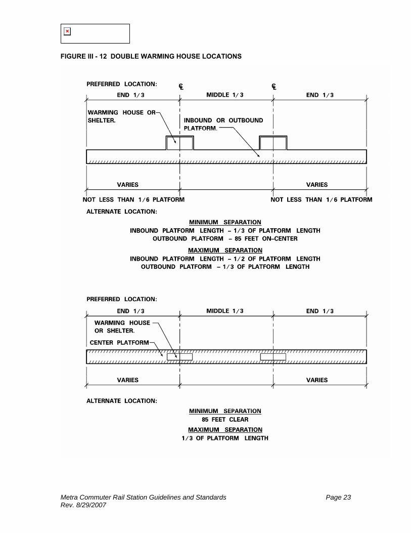
In general, when waiting area guidelines recommend the use of a warming house, a single warming house should be located as close as practical to the middle third of the platform. When platform or site constraints prohibit a single warming house to accommodate the required amount of waiting area, then a second warming house may be added. The two warming houses shall be located at approximately one third points along the length of the platform. A warming house used to supplement a shortage of space in a depot waiting room should be located equal distance from the depot and the end of the platform farthest away from the depot. Where possible, warming houses shall not encroach on the minimum platform clearances (including door swings) and shall not be located closer than 30 feet from platform access points. For center or island platforms, an accessible path must be provided on one track side of the warming house. See the sample of warming house locations in FIGURE III - 11 and FIGURE III - 12.

Metra Commuter Rail Station Guidelines and Standards Page 21 Rev. 8/29/2007
FIGURE III - 10 DEPOT LAYOUTS

Metra Commuter Rail Station Guidelines and Standards Page 22 Rev. 8/29/2007
FIGURE III - 11 SINGLE WARMING HOUSE LOCATIONS
Metra Commuter Rail Station Guidelines and Standards Page 23 Rev. 8/29/2007
FIGURE III - 12 DOUBLE WARMING HOUSE LOCATIONS

Metra Commuter Rail Station Guidelines and Standards Page 24 Rev. 8/29/2007
2. WAITING AREA
Refer to Section III.C for Waiting Area Guidelines
3. WAITING AREA VISIBILITY
Approaching trains should be visible from the waiting area. The design of the waiting area should incorporate the location of glazing for passenger visibility. The minimum height for glazing in the waiting area should be 24" above finished floor. The maximum glazing height should be between 6'- 8" and 7' - 2" above finished floor.
4. CEILING HEIGHT
All new warming houses shall have a minimum ceiling height of 9 feet above finished floor and preferably 10 feet at the center of the waiting area for installation of lighting, heating units and Voice of Metra speakers.
5. WAITING AREA SEATING
New and rehabilitated warming houses should provide a portion of the seating for fifteen (15) percent of the projected peak number of passenger boardings for the applicable platform. Existing single seat benches made of plastic shall be replaced. The benches and seating units should have individual seats, separated by dividers. New seating shall consist only of benches. They shall be constructed in a durable, weather-resistant, and vandal-resistant manner. They shall be anchored in a secure, tamper-resistant manner to the floor or wall.
6. ENTRY/EXIT DOORS
All warming houses shall have two entry/exit doors. One door shall be located at each end of the warming house.
7. EXISTING WARMING HOUSES
Existing warming houses in good condition shall be retained and rehabilitated as necessary to provide suitable visibility, lighting, ventilation and access for individuals with disabilities.
8. NEW WARMING HOUSES
New and replacement warming houses shall be constructed in accordance with the design and material standards of this Manual. All new construction shall conform to all applicable code and regulatory requirements. This shall include meeting ADA accessibility guidelines.

Metra Commuter Rail Station Guidelines and Standards Page 25 Rev. 8/29/2007
FIGURE III - 13 WARMING HOUSE SAMPLE LAYOUTS
Metra Commuter Rail Station Guidelines and Standards Page 26 Rev. 8/29/2007
N. SHELTERS
A single shelter shall be located as close as is practical to the middle third of the platform. When two shelters are required, the shelters should be located near the one-third points along the length of the platform. Where one or two shelters are used to supplement the space in a depot or warming house, they should be located equal distances from the structure and the end of the platform. Where possible, the shelters should be located at lease 30 feet away from a platform access point. An existing shelter which is in good condition, shall be rehabilitated, when it is cost-efficient to do so. Many existing shelters have architectural details which match the depot; these details shall be preserved and renovated. Whether new or renovated, the shelters shall comply with all local, state and federal codes, regulations and statutes. Existing single seat benches made of plastic shall be replaced. The benches and seating units should have individual seats, separated by dividers. New seating shall consist only of benches. They shall be constructed in a durable, weather-resistant, and vandal-resistant manner. They shall be anchored in a secure, tamper-resistant manner to the floor or wall. The seating should run along the back of the shelter, for two-thirds of its length. The glazing should allow passengers waiting within the shelter to see an approaching train and should also allow others to see into the shelter to see those inside. The minimum height of the bottom of the glazing should be 2.0’ above the finished floor. The maximum height of the top of the glazing should be 7’-2” above the finished floor.
O. ELECTRIC TICKETHOUSES/HEADHOUSES
1. ELECTRIC TICKETHOUSE / HEADHOUSE LOCATIONS
New and replacement electric tickethouse and headhouse locations on the station site are dependent upon the actual site conditions and the number of entries possible at a particular site. Electric tickethouses/headhouses typically occur at roadway viaducts or pedestrian tunnels. The relationships of the functional areas of electric tickethouse/headhouse are described in FIGURE III - 14.
Metra Commuter Rail Station Guidelines and Standards Page 27 Rev. 8/29/2007
FIGURE III - 14 ELECTRIC TICKETHOUSE/HEADHOUSE FUNCTIONAL RELATIONSHIP MATRIX
KEY: ♦ PHYSICAL ADJACENCY REQUIRED + CLOSE ADJACENCY DESIRABLE 0 NO ADJACENCY/SEPARATION NECESSARY - PHYSICAL SEPARATION DESIRABLE NOTE: NOT ALL AREAS AT ALL DEPOTS
2. TICKET VENDING MACHINE AREA (Metra Electric District)
Refer to FIGURE III - 15 for Ticket Machine Quantities
a) QUANTITY (Metra Electric District)
When a station has two electric tickethouses, each electric tickethouse shall have half the required number of ticket vending machines. There shall be a minimum of two ticket vending machines in all electric tickethouses.
b) LOCATION (Metra Electric District)
When possible ticket vending machines should be located so that there are separate queues for commuters who are purchasing tickets and for those who are passing through the electric tickethouse. Ticket vending machines should always be located near the main entry to the electric tickethouse unless site constraints prohibit it.
Metra Commuter Rail Station Guidelines and Standards Page 28 Rev. 8/29/2007
c) REVENUE COLLECTION (Metra Electric District)
An Automatic Revenue Collection System (ARCS) is used for selling tickets, collecting fares and allowing access into the electric tickethouse. The system is linked to the call for aid phones, the closed circuit television, and speaker system. The conduit sizes and the connections between systems are described in the Station Checklist in Appendix A.
d) CALL FOR AID PHONES (Metra Electric District)
A "call for aid phone" shall be located adjacent to the ticket vending machines. These phones connect with a central dispatch that will assist passengers having difficulties.
e) CCTV CAMERAS (Metra Electric District)
Closed circuit television (CCTV) cameras shall be located at all electric tickethouses to monitor entry and exit of passengers and prevent vandalism of ticket vending equipment. CCTV cameras should also be located at both levels of elevator lobbies where used in electric tickethouses, as well as in the elevator cabs.
3. ELECTRIC TICKETHOUSE AREA (Metra Electric District)
a) AREA
The number of ticket machines are based on projected peak number of alightings at a station (inbound or outbound alightings) during the next twenty years.
FIGURE III - 15 TICKET MACHINE GUIDELINES
Project Peak Passengers
No. of Ticket Machines
1 – 130 2 131 – 195 3 196 – 260 4 261 – 325 5 326 - 390 6 391 – 455 7 456 – 520 8 521 – 585 9 586 – 650 10 All new stations with a electric tickethouse shall be accessible for individuals with disabilities from a minimum of one electric tickethouse to the platform. New stations which do not initially require the future projected number of ticket vending machines at the time of opening, should have the space provided and set aside for their future addition. Existing stations with a single exit may require a second electric tickethouse/headhouse to accommodate the required number of ticket machines.
b) ENTRY/EXITING (Metra Electric District)
When doors are used to enter a electric tickethouse or exit onto the platform, the number of leaves at each shall match the number of ticket machines. If doors are not used at the electric tickethouse entry, then the minimum clear width shall be 27 inches times the number of ticket machines. For ADA accessibility, the minimum opening shall be 36". Also see the typical electric tickethouse/headhouse layouts for entry/exit sequences.
Metra Commuter Rail Station Guidelines and Standards Page 29 Rev. 8/29/2007
c) HEADHOUSE AREA
Guidelines to determine headhouse area can not be provided because the area is based on specific site conditions and ADA accessibility requirements for ramps or elevators. Stairway widths for new and replacement headhouses shall be based on the number of ticket machines at the electric tickethouse associated with a specific headhouse.
FIGURE III - 16 HEADHOUSE STAIRWAY WIDTH
No. of Ticket Machines
Minimum Stairway Width
Handrail Requirements
2 6'-0" Wide Handrails on both sides 3 7'-6" Wide Handrails on both sides & one at the one third point
of the stair width 4 10'-0" Wide Handrails on both sides & in the center 5 15'-0" Wide Handrails on both sides & at the one third point of
the stair width These standards allow each person moving up or down the stairs to hold on to a handrail. It considers that a person walking with a briefcase and/or purse requires a minimum of 27 inches clear width. All new stair and handrail dimensions shall conform to ADA accessibility guidelines.
d) EXISTING ELECTRIC TICKETHOUSES/HEADHOUSES
If in good condition, existing electric tickethouses and headhouses shall be renovated as necessary to comply with the ADA and to provide adequate visibility, lighting, ventilation and security.
e) NEW ELECTRIC TICKETHOUSES/HEADHOUSES
New electric tickethouses and headhouses shall be constructed in accordance with the design and material standards of this Manual. All new construction shall conform to all applicable code and regulatory requirements. New electric tickethouse and headhouse locations should be based on the prototype electric tickethouse/headhouse layouts unless site constraints restrict location and/or layout.

Metra Commuter Rail Station Guidelines and Standards Page 30 Rev. 8/29/2007
FIGURE III - 17 SAMPLE ELECTRIC TICKETHOUSE/HEADHOUSE LAYOUT AT A PED. TUNNEL
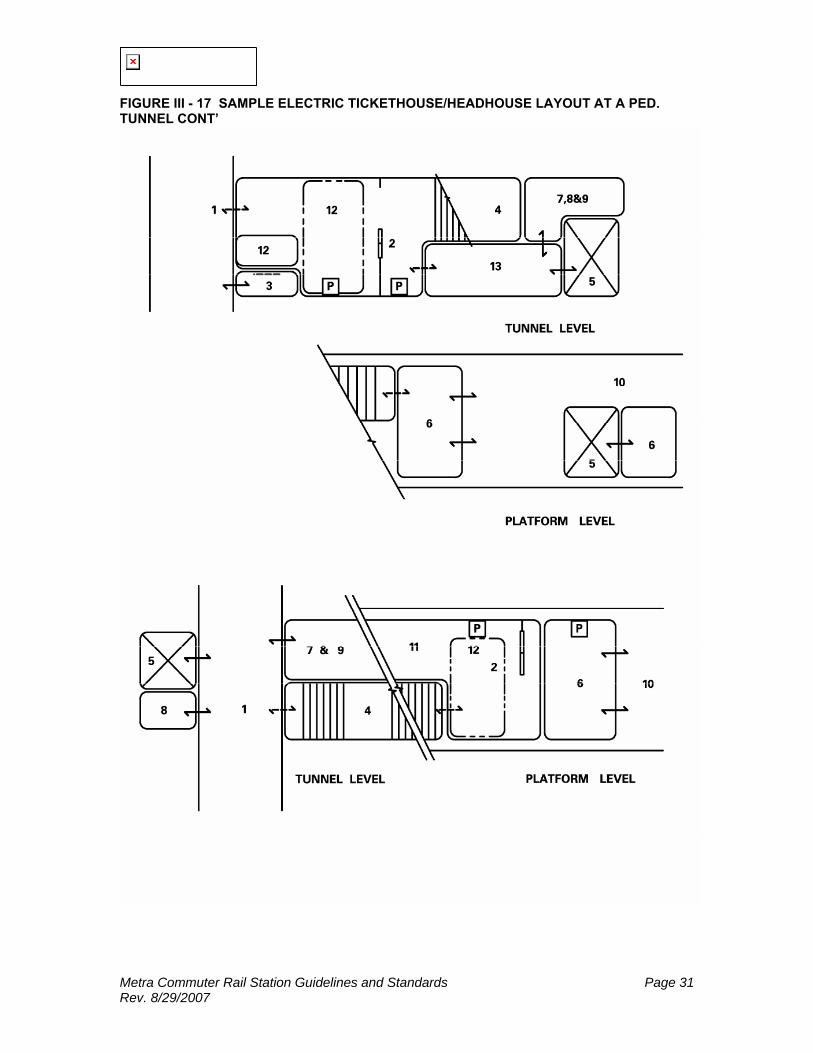
Metra Commuter Rail Station Guidelines and Standards Page 31 Rev. 8/29/2007
FIGURE III - 17 SAMPLE ELECTRIC TICKETHOUSE/HEADHOUSE LAYOUT AT A PED. TUNNEL CONT’

Metra Commuter Rail Station Guidelines and Standards Page 32 Rev. 8/29/2007
FIGURE III - 18 SAMPLE ELECTRIC TICKETHOUSE/HEADHOUSE LAYOUT AT A ROADWAY VIADUCT

Metra Commuter Rail Station Guidelines and Standards Page 33 Rev. 8/29/2007
P. SECURITY CONSIDERATIONS
1. GENERAL
Passenger security and protection of property against theft and vandalism are important factors in the design or rehabilitation of a station. Security issues for an individual station should be coordinated with Metra Police during the design of new and rehabilitated station projects.
2. SURVEILLANCE
Surveillance is the main security procedure that ensures passenger safety and protection of property. Station design should consider the visibility of paths from access points to station buildings and platforms. The design should also consider location of station buildings and platforms for surveillance by local and Metra police. After hour waiting zones could be established in station buildings and on platforms in areas providing the greatest visibility. Eliminating blind and unused areas and increasing the glazed openings of track level shelters will also improve surveillance. For special situations and for unavoidable blind corners, the use of vandal-resistant security mirrors is highly recommended. Reuse of surplus station spaces that encourage evening occupancy will provide additional security and surveillance. Refer to Section IV.C for Lighting Design Criteria. Night security lighting shall be provided to improve surveillance of station buildings, platforms and the overall site. Night security lighting shall be controlled by time-clocks for minimum operating costs. All waiting rooms shall be equipped with night security lighting. Security and surveillance lighting shall be integrated into general lighting systems.
3. VANDALIZED APPEARANCE
Any vandalized appearance of station facilities creates a negative image of Metra and invites further vandalism. All boarded-up areas, unused areas, or other signs of abandonment should be eliminated by opening, reglazing, refinishing, or resurfacing. Unused auxiliary facilities such as freight houses, shelters, shed or stairs should be removed where no reasonable possibility for reuse exists. Surfaces displaying evidence of severe vandalism should be resurfaced with more durable and more readily maintainable materials in accordance with the design and material standards in Chapter 6 of this Manual. Particular attention shall be given to underpasses/tunnels.
4. SPACE CONTROL
Access to spaces shall be restricted or controlled whenever necessary to maintain security. Each station should be carefully studied and evaluated for its specific requirements. The three main methods of space control are: lockable doors and pull down security shutters in station buildings and fences around parking lots.
5. LOCKABLE DOORS & PULL-DOWN SECURITY SHUTTERS
All interior doors within a depot shall be key-locked. Exterior depot doors facing away from the platform shall be key locked and exterior depot doors facing the platform may be key locked or have time locks.
6. SHIELDING
Shielding is defined as the use of protective screening and the use of break-resistant materials. Shielding represents an increase in material cost, but this cost is justified where replacement or excessive maintenance of less durable materials presents additional costs, inconvenience, and an antisocial appearance. The primary applications of shielding are for infrared heaters and for lighting fixtures.
Metra Commuter Rail Station Guidelines and Standards Page 34 Rev. 8/29/2007
a) SHIELDING FOR INFRARED HEATERS
All infrared quartz lamp heaters shall be provided with protective wire mesh screening and should be mounted out of reach of people standing on benches. All screening shall be removable or hinge operable for maintenance and all hardware and fastening systems shall be tamper resistant. The screening shall be durable and have a grid with a maximum 3/4 inch opening in any direction and shall not be closer than 3 inches from the quartz lamps. Refer to Appendix B for Historic Station Guidelines.
b) SHIELDING FOR LIGHTING FIXTURES
In general, all station facility lighting fixtures in commuter areas should be mounted out of reach, particularly in outdoor areas and in areas with a record of vandalism. Where low mounted fixtures are necessary in unattended areas, such as underpasses, these fixtures shall be constructed of vandal-resistant materials and equipped with shatterproof lenses.
7. COMMUNICATIONS AND REMOTE SURVEILLANCE
Communication, warning, and protection systems, including smoke detection, fire alarm and fire protection systems, must be provided in accordance with all applicable codes and regulatory requirements. Security and burglar alarm systems in ticket agent offices is required. Posting of notices indicating the presence of such security and burglar alarm systems is recommended as a criminal deterrent. All ticket agent offices should have concealed raceways to accommodate a motion detection system. Design and planning of all warning and protective systems shall be coordinated with Metra Police and the Communications Department. Fire alarm and fire protection systems shall also be coordinated with the local fire department. All security and burglar alarm activations for station premises shall terminate at both local police and Metra Police, and at AMTRAK Police where applicable. Remote surveillance systems are useful in locations where direct surveillance for personal safety cannot be attained. The presence of closed circuit television (CCTV) cameras may serve as a deterrent. However, the effectiveness of any remote surveillance system is dependent upon a timely response to any observed incident. Remote surveillance systems may also serve additional functions, such as monitoring ticket machine use in electric tickethouses and controlling access to elevators from an off-site location. CCTV cameras should be located for maximum visual coverage and for maximum protection from vandalism. Design and planning of all remote surveillance systems shall be coordinated with Metra Police and the Communications Department.
8. TICKET AGENT OFFICE SECURITY
The safety and security of the ticket agent and the security of the office contents is critical. Access to the ticket agent office must be controlled. The office must be designed as a self-contained environment to eliminate the necessity for the agent to leave while on duty. The ticket agent office shall have a toilet to eliminate the need to leave the office. The following are recommendations for ticket agent office security:
a) TICKET WINDOW
The ticket window must be glazed with a level 2 bullet-resistive, transparent material and shall be designed for ease of communication with ticket purchasers. The ticket window counter shall have a scoop tray for transactions and the partition below and on all sides of the window shall be constructed of a non-penetrable material. All ticket windows shall be furnished with removable window mini-blinds. The door shall be hinged to open to the office interior to avoid removal of the hinge pins. There shall be no glazing in the door or sidelights next to the ticket agent door. However, the door will have a peep hole.
b) INTERIOR WALLS AND WINDOWS
Interior walls for ticket agent offices in new and replacement depots shall be constructed of masonry. All windows at the ticket agent office will be non-operable and glazed with
Metra Commuter Rail Station Guidelines and Standards Page 35 Rev. 8/29/2007
polycarbonate glazing. Mini-blinds shall be provided at all exterior windows. All windows must be lockable.
c) SAFES AND DROP SAFES
Ticket agent office safes must be located out of the view of the general public. Safes shall be securely bolted to the floor. A drop safe shall be provided for each station that utilizes armored car pickup service.
d) HVAC
Refer to Section IV.A for HVAC Guidelines Heating, ventilating, and air conditioning for the ticket agent office shall be independent of the central system. The preferred air conditioning unit shall be a through-wall type securely mounted to the building wall, with fastenings secured from the office interior to prevent removal. The unit shall be mounted high on the wall to prevent vandalism. Remote units may be used if cost effective and location of the condenser is not subject to vandalism.
e) ALARMS
Conduit shall be installed in all new depots for the possible future installation of a silent alarm at the ticket agent window. Silent hold up alarms may be installed at existing depot ticket agent windows based upon recommendations of Metra Police and the Communications Department. When a silent alarm is activated by the agent, the alarm will notify the local police, Metra Police, and AMTRAK Police when applicable. An intrusion alarm may also be located outside the ticket agent office. Requirements for an intrusion alarm will be determined for each station in coordination with the Metra Police. An intrusion alarm is a secondary alarm placed inside the ticket office.
f) AGENT PARKING
A dedicated parking space shall be provided for each ticket agent per shift. The parking space shall be located as close as possible to the station building for the protection of the agent.

Metra Commuter Rail Station Guidelines and Standards Page 36 Rev. 8/29/2007
IV. MECHANICAL SYSTEMS
A. HEATING, VENTILATION & AIR CONDITIONING (HVAC)
HVAC systems are provided in station buildings to create a comfortable and controlled environment for commuters and station employees. The following guidelines have been established to aid the designer in achieving cost effective HVAC systems. These guidelines are based on accepted industry criteria and good engineering practice.
1. WAITING ROOMS
Passive solar design should be utilized wherever possible to reduce energy costs. Where possible, windows should be shaded to minimize summer heat buildup. All heating equipment designed for enclosed station buildings should be capable of maintaining the designated indoor temperature based on ASHRAE design parameters. All HVAC equipment shall comply with the requirements of applicable codes. All heating equipment with exposed heating elements should be vandal-resistant and/or mounted out of reach. Baseboard heating should be avoided.
a) HEATING REQUIREMENTS
The temperature for enclosed facilities should be maintained at 78º F minimum. Heating controls shall be equipped with a multiple set point clock thermostat and a manual on/off override switch. The system shall be equipped to allow a temperature of 55º F during after hours or as set back for operational requirements. Thermostat controls for passenger areas should be mounted in the ticket agent office or a lockable thermostat cover should be provided to prevent tampering of the controls.
b) VENTILATION & AIR CONDITIONING REQUIREMENTS
Mechanical ventilation is recommended for all enclosed facilities. Ventilation air change rates shall conform to applicable codes. Waiting rooms shall not have air conditioning. Natural ventilation should be provided in depot waiting rooms through the use of screened and operable windows. Temperature sensors shall be located above the ceiling space to trigger the ventilation exhaust fans. This sensor should be set at 80 degrees F. Ventilation fans shall be the induced draft type. The fan design capacity is determined on the basis of the facility's peak period. Air movement may be shared through parallel fan operation for passenger comfort. The station should be furnished with sufficient air intake mechanical dampened louvered vents to accommodate the necessary free air turnover requirements. Vent design should minimize infiltration during winter months. Combustion air should be provided directly to the burners to avoid equipment freeze up.
2. TICKET AGENT OFFICES
a) HEATING REQUIREMENTS
The ticket agent office shall be provided with a secondary heating system. Because the station's primary heating system is designed to maintain the temperature at 55 degrees F, the secondary heating equipment should have the BTU/HR capability to raise and maintain the ticket office temperature at 78 degrees F. Wall mounted heating controls shall be located inside the ticket agent office. The heating controls should include an on/off switch and thermostat. A safety interlock that resets the heater to a minimum 55 degrees F setting each time the ticket office door is opened should be considered.
b) VENTILATING & AIR CONDITIONING REQUIREMENTS
Air conditioning shall be provided for all ticket agent offices. A single wall mounted unit is preferred and should be incorporated into the design of the building. The equipment shall be capable of lowering and maintaining the ticket agent office temperature to 78 degrees F.

Metra Commuter Rail Station Guidelines and Standards Page 37 Rev. 8/29/2007
Equipment sizing shall be based on cooling 25% fresh air and 75% recirculated air. Controls shall be conveniently located for operation by the ticket agent. In all new or renovated ticket offices, ceiling fans shall be installed.
3. TOILET ROOMS
a) HEATING REQUIREMENTS
Restrooms shall be heated. Temperatures shall be maintained at 70 degrees F. Recessed fan coil units with thermostats should be considered.
b) VENTILATING REQUIREMENTS
Toilet facilities have mechanical exhaust ventilation required by code. Mechanical exhaust should be expelled directly to the outdoors at roof level. Control of mechanical exhaust equipment should be integrated with the on/off light switch. Air shall be provided through door louvers and/or door undercutting.
4. MECHANICAL EQUIPMENT ROOMS
a) HEATING REQUIREMENTS
Mechanical equipment rooms house heating and air conditioning equipment for station facilities. The mechanical room shall be heated to prevent equipment damage or water pipes freezing. When gas or oil fired heating equipment is used, the mechanical room shall be furnished with a chimney vent stack and duct work in accordance with applicable codes.
b) VENTILATION & AIR CONDITIONING REQUIREMENTS
The station should be furnished with sufficient air intake mechanical dampened louvered vents to accommodate the necessary free air turnover requirements. Vent design should minimize infiltration during winter months.
5. STATION ATTIC VENTILATION
Station buildings with pitched roof construction shall be furnished with a thermostatically controlled automatic attic ventilator. Ventilator controls shall be mounted in the mechanical room. The attic shall be provided with the required number of exhaust louvers. The exhaust louvers shall be equipped with insect screens.
6. WARMING HOUSES
a) HEATING REQUIREMENTS
All warming houses shall be heated by forced air systems, if possible. The minimum warming house temperature shall be 55 degrees F minimum. Thermostats and controls shall have a lockable cover to prevent tampering.
b) VENTILATION & AIR CONDITIONING REQUIREMENTS
Mechanical ventilation is recommended for all enclosed facilities. Ventilation air change rates shall conform to applicable codes. Warming houses shall not have air conditioning. Natural ventilation should be provided in warming houses through the use of screened and operable windows. Temperature sensors shall be located above the ceiling space to trigger the ventilation exhaust fans. This sensor should be set at 80 degrees F. Ventilation fans shall be the induced draft type. The fan design capacity is determined on the basis of the facility's peak period. Air movement may be shared through parallel fan operation for passenger comfort. The station should be furnished with sufficient air intake mechanical dampened louvered vents to

Metra Commuter Rail Station Guidelines and Standards Page 38 Rev. 8/29/2007
accommodate the necessary free air turnover requirements. Vent design should minimize infiltration during winter months.
7. SHELTERS
a) HEATING REQUIREMENTS
Shelters at stations with high ridership should consider the use of “in demand” ceiling mounted electric quartz lamp infrared heaters. Heaters shall be activated by a tamper-proof push button with a five minute timer shutoff. The heaters should also be provided with a sturdy wire-mesh vandal guard.
b) VENTILATION & AIR CONDITIONING REQUIREMENTS
Ventilation and air conditioning are not needed in a shelter.
8. ELECTRIC TICKETHOUSE/HEADHOUSE
a) HEATING REQUIREMENTS
If a electric tickethouse/headhouse is fully enclosed, it may be heated and ventilated. To prevent electric tickethouse entries and bottoms of stairways from icing, infrared heaters or slab heating should be considered. The temperature for enclosed facilities should be maintained at 78º F minimum. Heating controls shall be equipped with a multiple setpoint clock thermostat and a manual on/off override switch. The system shall be equiped to allow a temperature of 55º F during after hours or as set back for operational requirements. The thermostat shall have a lockable cover to prevent tampering with the controls.
b) VENTILATION & AIR CONDITIONING REQUIREMENTS
Mechanical ventilation is recommended for all enclosed facilities. Ventilation air change rates shall conform to applicable codes. A electric tickethouse/headhouse shall not have air conditioning. Natural ventilation should be provided in a electric tickethouse/headhouse through the use of screened and operable windows. Temperature sensors shall be located above the ceiling space to trigger the ventilation exhaust fans. This sensor should be set at 80 degrees F. Ventilation fans shall be the induced draft type. The fan design capacity is determined on the basis of the facility's peak period. Air movement may be shared through parallel fan operation for passenger comfort. The station should be furnished with sufficient air intake mechanical dampened louvered vents to accommodate the necessary free air turnover requirements. Vent design should minimize infiltration during winter months.
B. PLUMBING & FIRE PROTECTION
1. DEPOT
a) PLUMBING
There should be a janitor’s closet with a mop basin. There should also be a minimum of two external freeze-proof hose bibs, one at each end of the structure. For vendor areas within a depot, there should be hot and cold water and the waste lines provided. If the depot has a ticket agent office, there should be a drinking fountain. Floor drains shall be provided at recessed floor mats in vestibules. Floor drains shall also be provided in vendor spaces when cold and hot water is provided to the space.
Metra Commuter Rail Station Guidelines and Standards Page 39 Rev. 8/29/2007
b) FIRE PROTECTION
Sprinkler systems should be provided, if required by local code. The concealed sprinkler heads should be used. All mechanical equipment rooms housing gas fired heating equipment shall be equipped with a sprinkler system or a fire alarm system.
2. WARMING HOUSE
a) PLUMBING
If there is no depot present at a station site, then there should be a janitor’s closet with a mop basin. There should also be a minimum of two external freeze-proof hose bibs, one at each end of the structure. Floor drains shall be provided at recessed floor mats in vestibules. When a warming house exists in addition to a depot, no plumbing is necessary.
b) FIRE PROTECTION
Sprinkler systems should be provided, if required by local code. The concealed sprinkler heads should be used. All mechanical equipment rooms housing gas fired heating equipment shall be equipped with a sprinkler system or a fire alarm system.
3. SHELTER
No plumbing is required in shelters.
4. ELECTRIC TICKETHOUSE/HEADHOUSE
a) PLUMBING
In a electric tickethouse, plumbing is not normally required. There may be special circumstances where plumbing is required such as: a janitor’s closet, toilet, or vendor requiring water.
b) FIRE PROTECTION
Sprinkler systems should be provided, if required by local code. The concealed sprinkler heads should be used. All mechanical equipment rooms housing gas fired heating equipment shall be equipped with a sprinkler system or a fire alarm system.
C. ELECTRICAL SYSTEMS
1. GENERAL LIGHTING
The station lighting system should promote the safety, security, and comfort of the commuter. Appropriate lighting will also provide a deterrent to crime. The lighting system should provide the quantity of light required by the function of each individual area. Lighting equipment shall conform to the standards established in this Manual and shall be UL listed "suitable for the intended use". All conduit sizes shall conform to the applicable codes and to the recommendations in the Electrical Section of the Station Checklist in Appendix A. The lighting system shall operate continuously, relying on automatic and manual controls to provide efficient energy use. Vandal-resistant fixtures and lenses should be used as required. Lighting shall not interfere or blind train operators or cause a nuisance to neighboring property. The illumination levels for all station components are given in FIGURE IV - 3.
2. DEPOT
a) DEPOT EXTERIOR
The depot exterior shall be illuminated to promote security near the station. Some of the depot exterior lights shall remain on all night.

Metra Commuter Rail Station Guidelines and Standards Page 40 Rev. 8/29/2007
b) WAITING ROOM
Interior lighting shall provide general area illumination, and identify graphics and signs. The lighting design must include security and emergency lighting systems. Waiting rooms shall be designed for maximum use of natural lighting during daylight hours to minimize operating costs and to conserve energy.
c) TICKET AGENT OFFICE
Specific lighting is necessary at the ticket agent office and ticket window.
d) TOILETS
Toilets and storage rooms shall be provided with general illumination.
e) MECHANICAL ROOMS
Specific lighting is necessary in the mechanical equipment room.
f) CIRCUITS, CONTROLS, AND WIRING
Electrical circuits for passenger functions shall be separate from circuits for other areas of the station building. Power, lighting and smoke detector circuits shall be separate for all areas. Panels shall be located in the mechanical equipment room and accessible only to authorized personnel. Control switches for passenger areas shall be located in the ticket agent's office. Ticket agent office lighting shall be controlled by wall-mounted switches within the office, accessible only to the agent. All wiring shall conform to applicable codes. All conduit sizes shall conform to applicable codes. Handholes shall be adequately sized for wiring access by hand (minimum 6"X12").
g) POWER
Grounded duplex convenience receptacles shall be provided throughout the station building as required by applicable codes. Dedicated grounded receptacles shall be provided for ticket agent office equipment and other specialized equipment. Individual power circuits shall be provided for all hard-wired equipment. Receptacles shall be spaced at 6 foot intervals in the ticket agent office, and as required for housekeeping and maintenance purposes in other station areas. Receptacles in public areas shall have hinged covers to protect children.
h) EXTERIOR RECEPTACLES
Provide a minimum of one G.F.I. receptacle for each building elevation. Each receptacle shall have a lockable hinged cover.
3. WARMING HOUSE
Interior lighting shall provide general area illumination, and identify graphics and signs. Lighting design for stations must include night security and emergency lighting systems. Waiting rooms shall be designed for maximum use of natural lighting during daylight hours to minimize operating costs and to conserve energy.
4. SHELTER
Interior lighting shall provide general area illumination.
5. ELECTRIC TICKETHOUSE/HEADHOUSE
Interior lighting shall provide general area illumination.
Metra Commuter Rail Station Guidelines and Standards Page 41 Rev. 8/29/2007
6. PLATFORM
Platforms shall be adequately illuminated based on FIGURE IV - 4 over the entire length. A continuous conduit shall be provided for platform lighting.
7. PEDESTRIAN ACCESS
Lighting shall be provided for walkways, crosswalks, ramps, stairs, elevators, underpasses and overpasses. The lighting should direct the passenger to and from the platform.
8. STATION SITE AREAS AND PLATFORMS
Adequate lighting shall be provided in parking lots and at access points to the station entrances and platforms.
9. PARKING AREAS, BUS LOADING/UNLOADING, TAXI STANDS, & KISS-N-RIDE
Consult Metra's Project Manual for the Design of Surface Commuter Parking Lots, latest edition.
10. EMERGENCY OPERATION
Emergency lighting will be provided in accordance with all applicable codes. It shall be supplied by individual hard wired units with batteries that are charged while the power is on. In the event of normal power failure, these units shall provide illumination to assist in safe and orderly evacuation to the nearest station exit, emergency stairway or other area of safety. Illuminated exit signs must be provided in accordance with applicable codes.
11. SECURITY OPERATION
A number of fixtures within the facility should remain on at all times. This system must be on a separate and dedicated circuit for security lighting.
12. LIGHTING LEVEL CALCULATIONS
Lighting levels shall be calculated utilizing the following recommended "Illuminating Engineers Society Lighting Handbook", latest edition and methods. Minimum foot candles levels shall be maintained over 90% of the area. The lighting luminance values in FIGURE IV - 3shall be the average maintained illumination. Platform lighting is the exception to this rule. Platform lighting shall be the minimum foot candles provided, not the average maintained illumination. See FIGURE IV - 4 for the minimum platform lighting levels. The values of luminance shall have a uniformity ratio of 3 to 1 average to minimum, and not exceed the uniformity ratio of 5 to 1 maximum to minimum.
FIGURE IV - 1 AVERAGE ILLUMINANCE LEVELS – LUMEN METHOD
= Number of Luminaires x
Lumens per Luminaire (Area in Square Feet) x
Light Coefficient of Utilization x
Loss Factor
Average Maintained Luminance (Levels in Foot Candles) Area in Square Feet
Metra Commuter Rail Station Guidelines and Standards Page 42 Rev. 8/29/2007
FIGURE IV - 2 MINIMUM ILLUMINANCE LEVELS “POINT BY POINT” METHOD
=
Initial Candlepower of Source in Direction of Ray x
x
Cosine of the Angle between the Light Ray Perpendicular to the Plane at that Point x
x Light Loss Factor
Minimum Maintained Luminance Level (in Foot Candles)
Dist. from Sources to Point in Feet
FIGURE IV - 3 LIGHTING ILLUMINANCE VALUES AND LIGHTING CONTROL CRITERIA
STATION AREA AVERAGE ILLUMINANCE LEVELS (FOOTCANDLES)
LIGHTING CONTROL NOTES
Bus Loading/Unloading 2 3 Kiss-N-Ride Pick-up and Drop-off
2 3
Parking Area – open 1 3 - covered 5 3 Pedestrian Ways 1 3 Depot Loggia 5 3 Depot Entrance 10 2 Elevator/Stairs at point of transition
20 2
Passageways – Underpass 20 1 - Overpass 5 2 Waiting Area 20 2 Ticket Office – General 40 2 - Window 80 4 Janitorial Closets 20 4 Electrical & Mechanical Rooms
20 4
Storage Rooms 5 4 Toilets 20 4 Vendor Areas (By Tenant) 40 4
FIGURE IV - 4 LIGHTING ILLUMINANCE VALUES AND LIGHTING CONTROL CRITERIA
STATION AREA MINIMUM ILLUMINANCE LEVELS (FOOTCANDLES)
LIGHTING CONTROL NOTES
Platforms - Under Canopy 5 3 - At Platform Edge 2 3 LIGHTING CONTROL NOTES 1. To operate continuously. 2. To operate during all normal hours of operation. Night security lighting shall maintain a minimum of 2 foot candles in depot and warming house waiting areas and ticket agent offices. 3. To operate dusk to dawn with time clock and photo sensor override. Fifteen minutes after the last train leaves a station, time clocks shall turn off all lights except security lights and those necessary to maintain a minimum of 0.5 foot candles average at platforms, pedestrian walks, and parking areas. 4. Local switch.

Metra Commuter Rail Station Guidelines and Standards Page 43 Rev. 8/29/2007
D. COMMUNICATIONS SYSTEMS
The system provides information about train arrival and departure times, origination and destination points, the rail line served, train status, boarding location, and whether the carrier is AMTRAK or METRA. It also provides information about delays, service adjustments and emergencies. The “Voice of Metra” is a public address system which is required at all stations. The speakers should be optimized for voice reproduction. They should be spaced to provide uniform coverage of the station and waiting areas. The spacing and locations should be coordinated with the Metra Communications Department. The V.O.M. box is located outside the station structure preferably adjacent to the electrical control box. Wiring for the speakers should be run in metal conduits. Conduit sizes are listed in the Station Checklist, Appendix A.
1. DEPOT
a) WAITING ROOM
Locate recessed speakers in the ceiling
b) TICKET AGENT OFFICE
Locate recessed speakers in the ceiling for ticket agent to hear announcements from the central control point. Provide a microphone for the ticket agent to use when making announcements.
2. WARMING HOUSE
Locate recessed speakers in the ceiling
3. SHELTER
Locate speakers on the overhangs or eaves.
4. ELECTRIC TICKETHOUSE/HEADHOUSE
Locate recessed speakers in the ceiling
5. PLATFORM
Locate speakers on platform lighting poles a minimum of 16’ above grade for standard light poles and 10’ above ground for 14’ high ornamental poles.

Metra Commuter Rail Station Guidelines and Standards Page 44 Rev. 8/29/2007
V. LANDSCAPE DEVELOPMENT
A. GENERAL
Well-planned, properly maintained landscaping of the station site will create an attractive atmosphere for passengers and the community. Landscaping shall be in accordance with local community guidelines and Metra guidelines. Landscaping can be functional as well as decorative. Planting and landscaping materials can also be used to provide screening from adjacent residential properties, shape and define large parking areas, stabilize slopes and embankments, keep unpaved horizontal surfaces in good condition, and provide weather protection.
B. EXISTING PLANT AND LANDSCAPE MATERIAL
Where existing trees, shrubs, ground cover, and other landscape materials are part of a civic setting for a station, the landscaping and other materials shall be restored and maintained. Such landscaping materials may include existing lighting standards, signage, and walks.
C. SCREENING
Parking areas shall be screened from adjacent residential and civic areas. Plants designed for height and density to block views and protect the privacy of neighboring parcels shall be used for screening. Decorative screening material and fencing may be used where appropriate to supplement planting. Landscaping in ten-foot wide buffer zones is desirable. Screening and buffer zones should comply with applicable municipal code or requirements wherever possible.
D. TREES
Trees for landscaping shall be adequately sized for strength, appearance, and durability. The planting distance between trees and away from structures shall be a minimum of 30 feet. Evergreens shall be placed 5' back from curbs and sidewalks. Trees planted behind platforms shall be located so that at maturity the tree does not block the engineer’s view of the platform. Deciduous trees are preferred near platforms. Landscape design should consider the requirement of a 500' clear line of site at crossings.
E. EMBANKMENTS
Embankments shall be stabilized with low maintenance material that will prevent erosion and the growth of weeds and underbrush. Ivy is considered suitable surface material for embankments.
F. BUSHES
Bushes should be placed so as not to create blind areas for safety reasons.
G. UNPAVED GROUND SURFACES
Landscape materials such as brick pavers may be used to cover unpaved horizontal surfaces. Use of paving brick set in sand beds is preferred over grass for smaller non parking areas. On unpaved surfaces subject to damage, landscape material should be avoided. Grass, with a combination of plantings, is considered desirable for large unpaved surfaces. Low maintenance ground covers used with wood chip mulch are desirable for areas of moderate size near the station building. Wood chip mulch areas can be used for areas next to platforms since plantings can be damaged by deicing salt.
Metra Commuter Rail Station Guidelines and Standards Page 45 Rev. 8/29/2007
VI. MISCELLANEOUS ACCESSIBILITY GUIDELINES
A. GENERAL
All accessibility guidelines contained in this section and in the various other sections of this manual shall be in accordance with applicable guidelines set forth by the Americans with Disabilities Act.
B. SIGNAGE
Signage shall comply with the following minimum standards:
FIGURE VI - 1 SIGN CRITERIA
Raised & Braille Characters
Raised 1/32" uppercase sans serif type Braille: Grade 2
Finish & Contrast Eggshell matte or non-glare finish light characters on dark background or dark characters on light background
Character height 5/8" - 2" high characters. Signs mounted higher than 80" above floor - 3" minimum
Mounting Room and space designations installed on wall adjacent to latch side of door or nearest adjacent wall Centered 60" above floor Minimum 3" approach to sign without encountering protruding objects or standing in door swing
Station identification signs shall be placed to be visible from railroad passenger car windows. Signs identifying the station shall be placed on the four walls of the station which are either parallel or perpendicular to the tracks.
C. TELEPHONES
Where public pay telephones are installed, at least one pay phone at each location, exterior or interior, shall comply with the following minimum standards:
FIGURE VI - 2 TELEPHONE CRITERIA
Clear Floor Space
30" x 48" for forward or parallel approach with 27' knee space
Mounting Height
48" - Forward reach 54" - Side reach 44" Maximum height forward reach over obstruction 20" to 25" deep 34" maximum height side reach over obstruction 24" deep
Controls Push Button Cord Length 29" Minimum Volume Control Minimum one at each station
25% of all phones installed at station Text Phone Minimum one required at interior locations only Signage Display international symbol of access for hearing loss at each phone
equipped with volume control
Metra Commuter Rail Station Guidelines and Standards Page 46 Rev. 8/29/2007
VII. MATERIAL & PERFORMANCE STANDARDS
A. PLATFORMS
1. LOW LEVEL PLATFORMS
Low level platforms shall be constructed of treated timber and bituminous concrete with a nonskid surface on a suitable setting bed or base course. The platforms shall have timber perimeter curbing. Platforms shall have a 1/4" inch per foot slope away from trackside for proper drainage. Center platforms shall have a crown and be pitched 1/4" per foot for positive drainage from the center of the platform. Distance from the center line of tangent track to edge of trackside curbing shall be 5’-6”. For each degree of curvature on a curved track the distance from the center line of the track to the edge of trackside curbing shall be increased by 1”. Additional requirements for low level platforms can be found in FIGURE II - 1 MINIMUM STANDARD PLATFORM DIMENSIONS
2. HIGH LEVEL PLATFORMS
High level platforms shall be constructed of an armor deck with integral tactile warning and non slip surface on reinforced concrete piers with steel or concrete cross beams. Center platforms shall have a crown and be pitched 1/4" per foot slope away from the center of the platform for proper drainage. Distance from the center line of tangent track to edge of trackside curbing shall be 5’-7”. For each degree of curvature on a curved track the distance from the center line of the track to the edge of trackside curbing shall be increased by 1”. Additional requirements for high level platforms can be found in FIGURE II - 1 MINIMUM STANDARD PLATFORM DIMENSIONS
3. PLATFORM SEALERS
Asphalt platforms shall be seal coated on a periodic basis. Asphalt platforms should be seal coated at the time of construction, and should be seal coated on a three year maximum cycle. Seal coating shall be non-slip.
4. TACTILE STRIPS
Tactile strips shall be installed on all platforms. Metra will advise contractors and consultants of approved products acceptable for installation.
5. TACTILE STRIP CAULKING
The joints between the tactile strips and adjacent materials shall be sealed with exterior grade sealants, when necessary.
6. FENCING & GUARDRAILS
Platform fencing and guardrails should be constructed with woven wire fabric, chain link or metal tubing. The minimum fence height is 42 inches and the maximum opening width is 5 inches. The bottom of the fence should be a minimum of 5 inches above the top of the platform for ease of snow removal.
7. PLATFORM SEATING
Seating for platforms may be pressure-treated wood, concrete benches, or a special station design. To discourage loitering on platforms, the use of a backless seating unit is recommended. To discourage sleeping center armrests shall be installed.

Metra Commuter Rail Station Guidelines and Standards Page 47 Rev. 8/29/2007
8. PLATFORM LIGHTING FIXTURES AND POLES
Platform lighting fixtures should be the stem mounted "shoe box" type, with a recessed 250 watt high intensity discharge (HID) lamp. The fixtures should be mounted on painted steel or prefinished aluminum poles, generally 30 feet above the platform. Poles are to be spaced at approximately 100 feet apart. On the electric line, fixtures should be 12' to 15' above the top of the platform, spaced to provide the proper foot-candle level.
9. VOICE OF METRA
Voice of Metra is a public address system provided to the depot or warming house and to the inbound and outbound platforms. The outside speakers shall be attached to the standard platform light poles. Conduit for the wiring shall be run underground to inside of the poles. All light poles shall be provided with ½” holes for communication wires.
10. INTER TRACK DRAINAGE
Intertrack drainage is required at stations through the platform area where two or more platforms are present. The underdrains are typically 8 inch diameter perforated asphalt coated corrugated pipe. Catch basins, spaced approximately every 200 feet, are typically 36 inch diameter asphalt coated corrugated steel pipe with a poured in place concrete base and an open steel frame and grate. Any lateral or outfall pipe shall be asphalt corrugated steel pipe of the appropriate size. Placement of drains and pipe should be coordinated with intertrack fencing.
B. EXTERIOR WALLS
Primary considerations in the selection of exterior wall materials for station depots are weather resistance, protection, durability, structural integrity, fire resistance, initial cost, and maintenance. Masonry, both brick and concrete block, satisfies these considerations. Graffiti-resistant measures include the use of textured surfaces, coatings, and applied finishes. Masonry offers the advantage of integral coloring, thus eliminating the need for periodic painting. New foundation walls and finish floor heights shall be a minimum of 8" above the platform surface. This protects the finished surfaces from standing water, salts, and snow. Over the depot lifetime, when tracks and platforms are repaired and replaced, the finished height tends to rise. The 8" foundation wall can accommodate future height changes and protect the building from water damage. Brick may be used structurally or as a veneer surface over concrete block, wood, or metal frame construction. The brick finish may be carried into the depot interior as a unifying design treatment. Brick is noncombustible, abrasion resistant, and available in a variety of colors and textures. A clear graffiti-resistant coating may be applied to brick surfaces. FACE BRICK SHALL COMPLY WITH ASTM C216. MINIMUM GRADE: SW MINIMUM TYPE: FBS BRICK FOR REINFORCED MASONRY CONSTRUCTION SHALL COMPLY WITH ASTM C62. MINIMUM GRADE: SW CONCRETE BLOCK offers many of the same advantages of brick. Concrete block with textured decorative face treatments, such as split-face or fluted, is available. Concrete block can vary by volume, weight, bearing value, shrinkage, acoustics, and fire resistance. Concrete block may be used as a primary wall material or as a back-up for veneer applications. LOAD BEARING CONCRETE BLOCK SHALL COMPLY WITH ASTM C90. MINIMUM GRADE: N MINIMUM TYPE: TYPE I
Metra Commuter Rail Station Guidelines and Standards Page 48 Rev. 8/29/2007
C. ROOFING
Choosing the best roof membrane depends on the slope of the roof, the type of roof substrate to which the roof membrane will be installed, and the means of attaching the roof membrane to the roof substrate. In all retrofit roofing, materials to assure the structural capacity of the roof shall be reviewed by a structural engineer.
1. ASPHALT SHINGLE ROOFING:
For moderate to steep roof pitches on station buildings with wood roof framing, asphalt shingles are preferred because of the advantage of durability and an attractive appearance at a relatively modest cost. Some local municipalities may require wood shakes, slate shingles or roofing tiles to be used for design considerations. Asphalt shingles are equally useful for new roofing installations and reroofing applications. Asphalt Shingle Roofing is available with organic felt or fiberglass cores. Fiberglass cores are to be used because of their greater strength and resistance to moisture. Shingles are classified by their weight per square (100 square feet). These weights range from approximately 200 to 300 pounds per square. The heavier shingles are more durable and are used for relatively low roof slopes. The granular surface of asphalt shingles are available in a wide range of colors. The minimum roof slope for asphalt shingle roofs is 3 inches per foot. ASPHALT SHINGLE ROOFING SYSTEMS COMPLY WITH ASTM D3462-83, D225-80, D312-84 AND D226-82. THE SYSTEM SHALL HAVE A 20-YEAR WARRANTY.
2. BUILT-UP ROOFING
BUILT-UP ROOFING membranes consist of 4 layers of bitumen-saturated felt with alternating layers of bitumen, topped with a final layer of bitumen and gravel, or a mineral cap sheet as dictated by slope. Felt shall be glass fiber. Organic felts shall not be used. Bitumen shall be asphalt based. Coal tar pitch is unacceptable. Since the materials are flammable, a Class A built-up roofing system must be used. Built-up roofs should be pitched a minimum of 1/4 inch per foot for drainage. If the slope exceeds 1 inch per foot, the felt plies must be mechanically secured to the roof substrate. For slopes greater than 2 inches per foot, a mineral coated cap sheet must be used in place of the gravel surface. Built-up roofing is not suitable for roof slopes greater than 4 inches per foot. BUILT-UP ASPHALT ROOFING SYSTEMS SHALL COMPLY WITH ASTM STANDARDS: D312 (TYPE I, II, III, IV), D41, D549, D226 (TYPE I), D2626, D2828, D1863, AND D2178 (TYPE III OR IV). THE SYSTEM SHALL HAVE A 20-YEAR WARRANTY. A related built-up roof system is the Modified Bitumen Membrane. The modifying compounds improve cohesive strength, resistance to flow at high temperatures and toughness. The sheets may be fully-adhered, mechanically fastened, mopped in, or torch applied. These systems can be used within the same range of slopes as built-up roofing and are very suitable for reroofing applications. THE MODIFIED BITUMEN SYSTEM SHALL COMPLY WITH ASTM D226 (TYPE II), D2626, AND FOR HOT-MOPPED MEMBRANES - D312 (TYPE II, III, OR IV). THE MODIFIED BITUMEN SHEETS SHALL COMPLY WITH CGSB 37-GP-56M (CANADIAN GENERAL STANDARDS BOARD). THE SYSTEM SHALL HAVE A 20-YEAR WARRANTY.
3. SINGLE-PLY MEMBRANE ROOFING
SINGLE-PLY MEMBRANE ROOFING offers the advantages of quality control, simplicity of detailing, and ease of installation. One of the most reliable membrane materials is ethylene interpolymers (EIP) which can be adhered or mechanically fastened to the roof substrate or
Metra Commuter Rail Station Guidelines and Standards Page 49 Rev. 8/29/2007
loose-laid and ballasted. The adhered or mechanically fastened systems are preferred for retrofit station buildings to avoid the additional structural support needed for the ballast weight. Joints are minimal due to the large widths of membrane material. Joints may be made with solvents or heat welding. SINGLE-PLY ROOFING SHALL COMPLY WITH ASTM STANDARDS: D-573, D-2565, D-751, D-471, D-1204, D-2136, AND E-96. THE SYSTEM SHALL HAVE A 20-YEAR WARRANTY.
4. STANDING SEAM METAL ROOFING
STANDING SEAM METAL ROOFING is extremely reliable and durable. The standing seam provides a watertight mechanical joint between roofing panels and is an attractive architectural element of the roof. Metals used are aluminum, copper, Monel, steel (galvanized, stainless, and terne coated), and zinc alloy. No lead coated metal roofing is to be used. Of these, aluminum, steel, and zinc are available in prefinished colors. Standing seam metal roofing should be used on roofs with a slope of 3 inches per foot or greater. STANDING SEAM METAL ROOFS SHALL BE A MINIMUM 24 GA. STEEL OR .032" ALUMINUM. THEY SHALL COMPLY WITH ASTM STANDARDS: STEEL: HOT-DIP ZINC-COATED STEEL SHEET, ASTM A446, GRADE A. ALUMINUM: ASTM B209; ALLOY, TEMPER AND MILL FINISH. THE SYSTEM SHALL HAVE A 20-YEAR WARRANTY.
D. SOFFITS AND LOGGIAS
Soffit panels and depot loggia ceiling panels should be durable and resistant to the elements. When compatible for exterior use, the interior ceiling material may be continued to the exterior loggia soffit. Typical materials are metal panels, composition panels, water resistant gypsum board or Portland Cement plaster.
E. INSULATION
Insulation is an important consideration when choosing building systems. It not only controls the flow of heat and conserves energy, but also prevents water vapor condensation and transmission, and can provide support for a finish surface or facing. Structures with more than one story may require ceiling/floor assembly insulation. The minimum required R-values for all assembly types vary by state and local codes. Metra stations shall follow current American Safety of Heating, Refrigerating and Air Conditioning Engineers standards unless local codes are more stringent.
1. WALL INSULATION
WALL INSULATION must be compatible with the type of wall system constructed. The typical masonry cavity wall consists of rigid insulation board and a 1/2" minimum air space. There are many types of rigid board available. Fiberboard should not be used because of its tendency to decompose. Closed cell foamed plastics have a high thermal resistance and a good resistance to moisture absorption and water vapor permeability. Polystyrene and polyurethane are the most common of the rigid foam insulations. The thickness of the rigid board will depend on the required R-value. Each inch of rigid insulation board has a thermal resistance (R-value) in the range of 3.85 to 6.2, depending on type.
2. ROOF INSULATION
ROOF INSULATION must be compatible with the roofing membrane and the roof substrate. Tapered insulation systems may be used to slope to the roof drains. Fiberglass batt insulation between the roof structural members is the most common insulation for asphalt shingle roofing. The thickness varies according to the attic/roof assembly R-value requirements. Blown fiberglass insulation may also be used. Rigid insulation boards are the most common insulations for built-
Metra Commuter Rail Station Guidelines and Standards Page 50 Rev. 8/29/2007
up roofs. Polyisocyanuate boards combined with wood fiberboards will typically attain the required roof R-values with the minimum amount of insulation thickness. Glass fiber reinforced boards are acceptable, though more expensive than polyisocyanuates. Rigid insulation boards of polyisocyanuate, polystyrene, polyurethane and reinforced glass fiber are common insulations for single ply roofing systems. Mechanically fastened single ply systems will often limit thickness and types of insulation used. Fiberglass batt insulation is the most common insulation for standing seam metal Roofing. The thickness of the batts is related to the roof structural member sizes. Rigid foam boards may also be used. Specialized metal standing seam roofing systems have a composite panel preformed foam insulation and metal panels. Fiberglass batt insulation is the most common floor/ceiling assembly insulation. The thickness and R-value are dependent on code requirements and type of floor structure. Blown fiberglass may be used as well. RIGID FOAM INSULATION BOARDS SHALL COMPLY WITH ASTM STANDARDS: C578-87, C591, C726 AND C728. BATT OR BLANKET INSULATION SHALL COMPLY WITH ASTM STANDARD C665, AND FEDERAL SPECIFICATIONS HH-I-521F.
F. DOORS AND HARDWARE
Refer to Section VII.G for additional Glazing Criteria. Pivoted (balanced) single or double leaf swing doors shall be used for exterior doors at all stations excluding historic structures. These doors are aluminum and a maximum two-thirds glazed. Hinged single leaf swing doors are recommended for interior use. The doors may be solid core wood or hollow metal. Doors shall be fire-rated and UL labeled where required. All exterior doors shall be weatherstripped for energy conservation and equipped with magnetic time locks. Automatic door operators are not recommended because of high initial cost and the need for frequent maintenance services. Panic hardware shall be installed on the exterior doors required by code for emergency exiting.
1. ALUMINUM ENTRANCE DOORS
Ellison Balanced Doors manufactured by Ellison Bronze Co., Inc., with two-thirds glazing are the Metra standard for exterior passenger doors. These doors may be supplied with transoms and sidelights. The number and location of entrance doors at a new depot shall be in accordance with the planning and design guidelines of Chapter 2 of this Manual. ALUMINUM ENTRANCE DOORS SHALL COMPLY WITH ASTM B 209-86, ASTM B221-85A, ASTM C 1048-85, AND CPSC-16 CFR PART 1201 - SAFETY STANDARD FOR ARCHITECTURAL GLAZING MATERIALS.
2. SOLID CORE FLUSH WOOD DOORS
SOLID CORE FLUSH WOOD DOORS are suitable for the interior of station buildings; hollow core flush wood doors shall not be used. Face veneers may be either painted or stained. Wood door thickness shall be 1-3/4 inches. WOOD DOORS SHALL COMPLY WITH AWI STANDARDS: DOOR GRADE: CUSTOM VENEER FACE GRADE: II CORE: RATED DOOR: DEPENDENT ON CODE REQUIREMENTS NON-RATED: FLC-7 OR BETTER
3. STEEL HOLLOW METAL DOORS
STEEL HOLLOW METAL DOORS are suitable for heavy use installations in station buildings. For exterior use, insulated hollow metal doors are recommended and shall be 1-3/4 inches thick. HOLLOW METAL DOORS SHALL COMPLY WITH SDI STANDARDS:

Metra Commuter Rail Station Guidelines and Standards Page 51 Rev. 8/29/2007
DOOR GRADE: II DOOR MODEL: INSULATED - 2 OR 4 HOLLOW - 1 OR 3
4. PRESSED STEEL DOOR FRAMES
PRESSED STEEL DOOR FRAMES are recommended for both wood and steel doors. All frames shall have anchors suitable for the adjacent wall or partition material.
5. HARDWARE
HARDWARE for station doors shall be heavy duty commercial type. All public access doors shall be equipped with delayed action closing devices to meet ADA accessibility requirements. Entry door push/pull hardware shall consist of a horizontal push bar and an offset pull handle. Interior doors to ticket agent offices and toilet rooms shall have overhead closers. Locksets shall be used for control of spaces and for security. Products manufactured by Best Lock Corporation are currently used by Metra. A master keying system shall be provided for each depot facility. All station keying systems shall be compatible so that a grandmaster key may be used throughout the system. Exterior doors shall have deadbolts. Interior doors shall have doorstops or bumpers to prevent damage to adjacent surfaces. Storage, janitor closet and mechanical room doors shall be key-locked. Restroom doors shall have privacy locks. Depot waiting area doors may have time locks and panic hardware installed as required by Metra. Ticket agent office doors shall be equipped with snap type locks and with dead bolt locks for employee protection. They shall also have wide-angled peep holes, so that the ticket agent can survey the area before opening his door. HARDWARE SHALL COMPLY WITH ANSI, SECTIONS A117.1, A156.1 THROUGH A156.18, NFPA 101 AND DHI.
6. ALUMINUM OVERHEAD ROLLING GRILL
ALUMINUM OVERHEAD ROLLING GRILL shall be used to separate a portion of the waiting area vestibule designated for use as a 24 hour waiting area. This allows for the 24 hour waiting area to be heated by the same system that heats the rest of the depot waiting area. WINDOWS Security shutters and grills may either be steel or aluminum. Steel shutters shall be a minimum of 22 gauge, and hoods a minimum of 24 gauge. Aluminum shutters shall be a minimum of .50" thick and hoods a minimum of .040". There are two basic types of windows at a depot, fixed and operable. Operable windows are preferable for station depots that are manned by ticket agents, because they provide natural ventilation. Depots without ticket agents should not have operable windows. Sliding windows, double-hung or gliding types, shall be used when the installation of exterior screening is desired. All operable windows shall be lockable. Window frames of aluminum, vinyl claded, or wood construction are suitable for station structures. Complete caulking of the perimeter of all window frames with a weather-resistant sealant is necessary to reduce air infiltration and subsequent heat loss. Sealants are available in color ranges to match window frames.
G. WINDOWS
1. ALUMINUM WINDOWS
ALUMINUM WINDOWS shall be given a protective finish of either alumite for a natural finish or an anodized paint for color. ALUMINUM WINDOWS SHALL COMPLY WITH ANSI/AAMA 101: GRADE: COMMERCIAL (C) PERFORMANCE CLASS/DESIGN PRESSURE: MINIMUM OF 20 PSF BOTH INWARD AND OUTWARD
Metra Commuter Rail Station Guidelines and Standards Page 52 Rev. 8/29/2007
2. WOOD WINDOWS
WOOD WINDOWS shall have a vinyl clad finish for ease of maintenance. VINYL CLAD WOOD WINDOWS SHALL COMPLY WITH ANSI/AAMA 101V: GRADE: COMMERCIAL (C) PERFORMANCE CLASS/DESIGN PRESSURE: MINIMUM OF 20 PSF BOTH INWARD AND OUTWARD.
3. SLIDING WINDOWS
SLIDING WINDOWS are acceptable for station depots because the opened window does not project from the wall and does not obstruct circulation.
4. DOUBLE-HUNG WINDOWS
DOUBLE-HUNG WINDOWS are available in a wide range of standard sizes, making them suitable for a variety of architectural treatments. Windows shall be furnished with a secure locking device operable from the interior. Double-hung windows provide openings at the top and bottom of the window for ventilation in warm weather.
5. HINGED OR AWNING WINDOWS
HINGED OR AWNING WINDOWS have the disadvantage of projecting from the wall when opened. Hinged windows should be installed only in areas that do not obstruct commuter paths.
6. GLAZING
Window glazing material should permit visibility into the station interior as well as providing natural light. Glazing should be clear; textured or patterned material should be avoided. Glazing material may be tinted. Reflective coatings are not recommended for station glazing because visibility into the station is diminished. To maximize safety and minimize replacement cost, resistance to breakage is an important factor in the selection of glazing material. The different types and applications of suitable glazing materials are included below.
7. GLASS
a) LAMINATED SAFETY GLASS
LAMINATED SAFETY GLASS consists of a layer of transparent plastic sandwiched between two layers of glass. The plastic layer provides shatter resistance, and holds the piece in place if the glass is broken. Because of its shatter resisting properties, laminated safety glass is preferable to tempered glass for station windows. When laminated glass is divided into smaller, individual panes, there is less potential for breakage and they are easier and more cost efficient to replace. Laminated safety glass is more expensive than tempered glass and is usually reserved for use in skylights, and when required by building code. SAFETY GLASS SHALL COMPLY WITH CONSUMER PRODUCT SAFETY ACT REGULATIONS SECTION 16 CFR PART 1201 - SAFETY STANDARD FOR ARCHITECTURAL GLAZING MATERIALS.
b) TEMPERED GLASS
TEMPERED GLASS is treated at a high temperature. Upon failure, tempered glass breaks into small fragments. Tempering also increases resistance to wind loads and thermal stress. See the CPSC Safety Standard for Architectural Glazing Materials and applicable building code requirements, for locations where tempered or safety glass will be required. TEMPERED GLASS SHALL COMPLY WITH ASTM C1048.
Metra Commuter Rail Station Guidelines and Standards Page 53 Rev. 8/29/2007
c) FLOAT GLASS
FLOAT GLASS may be used at some station locations. The minimum thickness of float glass shall be 3/16". The maximum length or width the glazing pane shall be 36". FLOAT GLASS SHALL COMPLY WITH ASTM C1036.
d) POLYCARBONATE GLAZING
POLYCARBONATE GLAZING is more resistant to impact than glass and should be considered in high vandal areas. It is less resistant to surface scratching and requires protective treatment protection from ultraviolet light. Surface treatments should be used to improve resistance to weathering and abrasion. Polycarbonate glazing shall be 3/16" thick and the maximum pane dimension shall be 36". POLYCARBONATE GLAZING SHALL COMPLY WITH ASTM D702 AND D1547.
8. FRAMING & INSTALLATION:
All new window frames shall be designed so that float glass and polycarbonate glazing may be installed interchangeably. Since polycarbonate glazing expands up to four times as much as glass does, careful attention must be paid to the design of window frames and rabbet depths. The glazing should be installed so that the material is free to expand and contract without restraint. When installed within a channel frame, the rabbet depth should be sufficient to allow for thermal contraction and foreshortening due to deflection, without withdrawing from the edges of the frame. Through-bolting or use of other inflexible fasteners for polycarbonate glazing should be avoided. FIGURE VII - 1 shall be used in the design of new window frames. It defines the minimum clear space required between the edge of polycarbonate glazing and the inside corner of rabbet. The corresponding allowance for expansion of the polycarbonate glazing is also shown.
FIGURE VII - 1 MINIMUM RABBET DEPTHS
Long Dimension Short Dimension Up to 24” 24” – 36” 36" - 60" 60" - 72" 72" - 96" 96" - 120"
Up to 24" 3/8" 7/16" 1/2" 9/16" 5/8" 11/16" 24" to 36" 9/16" 5/8" 11/16" 3/4" 13/16" 7/8" Polycarbonate Glazing Expansion Allowance
1/16" 1/8" 3/16" 1/4" 5/16" 3/8"
SECURITY SCREENING may be necessary for shielding of station Several manufacturers offer systems that combine security and insect screening, utilizing high tensile strength stainless steel mesh in aluminum or steel frames with concealed hardware and fastenings
9. TICKET AGENT'S WINDOW
TICKET AGENT'S WINDOW shall be the bullet-resistant standard service window by Chicago Bullet Proof Equipment Company. The assembly includes a level two caliber bullet-resistant window, a metal counter and coin tray. The removable window mini-blinds are not included in the assembly, but should be installed at each ticket agent's window.

Metra Commuter Rail Station Guidelines and Standards Page 54 Rev. 8/29/2007
H. INTERIOR PARTITIONS
Refer to Section VII.B for Brick and Concrete Standards Partitions in passenger areas of commuter rail stations shall be durable and resistant to damage. Integrally colored materials are preferable to applied finishes for durability and ease of maintenance. Partitions enclosing ticket agent office facilities shall be masonry and shall extend through any suspended ceilings to the structure above for security.
1. BRICK
BRICK is a suitable material for interior partitions where brick is used as the exterior facing of the station depot. Brick is available in several sizes and in a variety of colors and textures; it offers the advantages of being incombustible and abrasion-resistant. A clear graffiti-resistant coating may be applied to brick surfaces for additional protection. Brick partitions may be double width for brick finish on both sides, or a concrete block masonry backup may be used where only one side of the partition faces a passenger area.
2. CONCRETE BLOCK
CONCRETE BLOCK offers many of the advantages of brick and is a good material for fire-rated walls. A rough-textured decorative face treatment is often used to discourage graffiti. Plain-faced standard concrete block may be used as a backup material for brick or tile facing or exposed in areas such as storage and mechanical rooms. Concrete block may be painted.
3. GLAZED FACE BRICK & BLOCK
GLAZED FACE BRICK & BLOCK is a decorative and easily maintained finish suitable for passenger areas. The material is available in a wide range of colors and patterns that may be combined for decorative effects. The use of this material shall be limited to the interior of a structure. GLAZED FACE MASONRY UNITS, FOR INTERIOR USE ONLY, SHALL COMPLY WIYH ASTM C-126 STANDARDS: GRADE: S TYPE: I
4. PLASTER WALLS
PLASTER WALLS consist of plaster applied to a metal lath supported by wood or metal stud framing. Metal studs are preferred for station buildings because of the ease and speed of installation. Though less durable than masonry partitions, plaster construction is suitable for station renovation work where the existing structure may not be capable of supporting the greater weight of masonry. It may also be used for new construction. Where plaster walls are used with ceramic tile in areas where moisture can form, such as in toilet rooms, a water-resistant surface must be used. LATH AND PLASTER SHALL COMPLY WITH ASTM STANDARDS: C841, C842, C926 AND ANSI A42.3.
5. WATER RESISTANT GYPSUM BOARD
WATER RESISTANT GYPSUM BOARD and composite board such as "duo-rock" may be used in lieu of plaster in wet areas. WATER RESISTANT GYPSUM BOARD SHALL COMPLY WITH ASTM C630.
Metra Commuter Rail Station Guidelines and Standards Page 55 Rev. 8/29/2007
6. GLASS BLOCK
GLASS BLOCK: Solid structural grade glass block with a clear, smooth surface is the only glass block that may be used as a partition material. The glass block must sit on a housekeeping base, a minimum of 4" above the floor surface, raised to match adjacent bases within the room. THE MORTAR SHALL COMPLY WITH ASTM C150 (TYPE I CEMENT), ASTM C207 (TYPE S HYDRATED LIME), ASTM C144 (AGGREGATES), AND ASTM C207.
7. PARTITION FINISHES
Applied finishes are necessary for both plaster and drywall construction and may be needed for concrete block masonry. Finishes should be limited to paint and similar coatings and to glazed ceramic tile. Vinyl fabric wall coverings and wood and plastic paneling should not be used in passenger areas of station buildings.
a) PAINT.
PAINT is the least costly finish treatment for interior partitions. Semi-gloss alkyd enamel shall be used for ease of cleaning and durability. A primer and two coats of paint should be applied. Exposed standard block may be painted with masonry paint on the interior face only. PAINTS SHALL COMPLY WITH ASTM D, ALL APPLICABLE SECTIONS. PLASTER/DRYWALL PARTITIONS: A MINIMUM OF ONE PRIMER COAT AND TWO COATS OF SEMI-GLOSS ALKYD ENAMEL. MASONRY: A MINIMUM OF ONE COAT OF BLOCK FILLER AND TWO COATS OF SEMI-GLOSS ALKYD ENAMEL. (INTERIOR MASONRY ONLY.) MINIMUM REFLECTANCE: ELECTRIC TICKETHOUSE/HEADHOUSE WALLS AND CEILINGS SHALL HAVE A MINIMUM REFLECTANCE VALUE OF 80.
b) GLAZED CERAMIC TILE
GLAZED CERAMIC TILE is recommended for toilet rooms. It provides excellent protection in moisture areas and is easily cleaned. Ceramic tile is available in a wide range of colors and may be considered for decorative use in other station depot areas. CERAMIC WALL TILE SHALL COMPLY WITH THE AMERICAN NATIONAL STANDARD SPECIFICATIONS FOR THE INSTALLATION OF TILE, SECTIONS A108.1 THROUGH A108.10. GROUT AND MORTAR SHALL COMPLY WITH THE AMERICAN NATIONAL STANDARD SPECIFICATIONS FOR MATERIALS, SECTIONS A118.1 THROUGH A118.8, A136.1 AND A137.1.
I. FLOORING
Depot flooring materials shall be suitable for high volume traffic, heavy usage, and ease of maintenance. Hard surfaced flooring is preferable to resilient flooring for passenger areas. When a radiant floor heating system is used, hard surface flooring is to be used.
1. QUARRY TILE
QUARRY TILE is a good material for waiting rooms and passenger traffic areas. It is long-wearing and nonskid. The availability of colors and patterns permit the design of floors for both functional and decorative purposes. Quarry tile shall be a minimum of 3/4" thick. QUARRY TILE SHALL COMPLY WITH THE NATIONAL RESEARCH COUNCIL (NRC), SECTION 206.
Metra Commuter Rail Station Guidelines and Standards Page 56 Rev. 8/29/2007
2. TERRAZZO
TERRAZZO is a durable, long-lasting material suitable for use in high traffic areas and requires little maintenance. Terrazzo shall be a "sand-cushion" cast-in-place system. TERRAZZO SHALL COMPLY WITH THE NATIONAL TERRAZZO AND MOSAIC ASSOCIATION.
3. NON-SLIP UNGLAZED CERAMIC TILE
NON-SLIP UNGLAZED CERAMIC TILE is the recommended flooring material for restrooms. This tile is wear-resistant and has a non-slip surface. UNGLAZED CERAMIC TILE SHALL COMPLY WITH THE TILE COUNCIL OF AMERICA RECOMMENDED STANDARD SPECIFICATIONS FOR CERAMIC TILE.
4. CONCRETE FLOORING
CONCRETE FLOORING is suitable for non-public areas such as storage rooms, mechanical equipment rooms and in unfinished vendor areas. Concrete additives and toppings can be used to improve hardness, chemical resistance, and slip-resistance. CONCRETE FLOORING SHALL COMPLY WITH THE AMERICAN CONCRETE INSTITUTE (ACI), SECTION 320-80. SLAB FINISHES AND ADDITIVES THAT IMPROVE HARDNESS, CHEMICAL RESISTANCE, AND SLIP-RESISTANCE SHALL COMPLY WITH ACI 320-80 STANDARDS.
5. RESILIENT RUBBER FLOORING
RESILIENT RUBBER FLOORING may be used in elevators and in the ticket agent offices. It is long-lasting, durable and has an anti-slip surface. Resilient rubber flooring is easily cleaned and requires low maintenance. Resilient rubber flooring shall have a raised stud pattern with a minimum base thickness of 3/16" and a minimum stud height of .05".
6. FLOOR MATS
a) RECESSED FLOOR MATS
RECESSED FLOOR MATS should be located at the entry vestibules. Floor mats eliminate slippery floor surfaces and keep the waiting area floor clean since the tread design provides a self-cleaning surface. Vinyl and vinyl abrasive surfaces are recommended and provide maximum wear and slip resistance. Carpeted treads shall not be used. The system should allow replacement of single tread rails without dismantling the entire grid system. The mats can be installed in either a level base, a shallow pit with a drain pan, or a deep pit with a drain attachment. At some depots, the slab thickness may only be capable of having a level base or shallow pit mat. Where a thick slab can be provided, a deep pit mat with a drain attachment should be installed at heavy traffic locations.
b) ANTI-FATIGUE FLOOR MATS
ANTI-FATIGUE FLOOR MATS shall be located in each ticket agent's office, below the seat at the ticket window. This is to provide some comfort during the rush hours where the ticket agent will be standing at the window for an extended period of time.
J. CEILINGS
Station depot ceilings shall maximize sound absorption and minimize sound transmission and reverberation. A suspended ceiling is desirable as the space above the ceiling may be used for lighting fixtures, ductwork, sprinkler systems, etc. The height of the ceiling above the floor should

Metra Commuter Rail Station Guidelines and Standards Page 57 Rev. 8/29/2007
be appropriate for the room dimensions, generally one-half the horizontal dimension. Waiting room ceilings shall not be less than 9 feet in height. Ten feet is the preferred height to prevent vandalism. Ceiling mounted general lighting fixtures shall be recessed with lenses flush with the plane of the ceiling. Special decorative lighting fixtures may be surface mounted or suspended from the ceiling. Ceilings should be white or off-white for light reflection.
1. ACOUSTICAL WOOD FIBERBOARDS
ACOUSTICAL WOOD FIBERBOARDS such as the Tectum Acoustic-Tough Ceiling System, by Tectum Inc., is preferred for public areas. "Tectum" is a high impact wood fiber product that is durable and vandal resistant. ACOUSTICAL WOOD FIBERBOARDS SHALL COMPLY WITH ASTM E1264.
2. METAL ACOUSTICAL CEILING
METAL ACOUSTICAL CEILING panels may be used in waiting rooms and other passenger areas. Metal panels should be considered if ceiling heights are less than 10 feet. The system utilizes a perforated reinforced metal ceiling panel with sound absorbing filler material supported on a concealed grid suspension. It is less susceptible to damage and non-combustible. METAL PAN ACOUSTICAL CEILING SYSTEMS SHALL COMPLY WITH ASTM E1264.
3. MINERAL FIBER ACOUSTICAL CEILING PANELS
MINERAL FIBER ACOUSTICAL CEILING PANELS may be used in ticket agent offices and other areas less subject to vandalism. They may also be used in waiting areas, if the ceiling height is 10 feet or greater. Panels are supported on an exposed metal grid suspension system and provide excellent acoustic control. MINERAL FIBER ACOUSTICAL PANELS SHALL COMPLY WITH ASTM E1264.
4. GYPSUM BOARD OR PLASTER ON METAL LATH
GYPSUM BOARD OR PLASTER ON METAL LATH: are suitable for sloped ceilings, storage rooms, restrooms, and mechanical equipment rooms. Paint is recommended for the finish of these ceilings. GYPSUM BOARD SHALL COMPLY WITH ASTM C36. GYPSUM BOARD USED IN WET LOCATIONS, SUCH AS RESTROOMS AND EXTERIOR APPLICATIONS, SHALL COMPLY ASTM C630. LATH AND PLASTER COMPLY WITH ASTM STANDARDS C841, C842, C926 AND ANSI A42.3.
K. WAITING AREA SEATING
New waiting room seating shall be benches that are placed along the waiting area perimeter. Molded plastic seating is not to be used. Seating shall either be anchored to the floor or wall-mounted. Wherever possible, wall mounted benches are preferred to facilitate floor cleaning beneath. Waiting room area seating should offer reasonable comfort to users through contoured design and sturdy construction. Wooden slat benches shall be oak for interior applications and red cedar or redwood for exterior uses. Armrests shall be placed between the seats and at the end of benches.

Metra Commuter Rail Station Guidelines and Standards Page 58 Rev. 8/29/2007
L. WARMING HOUSES
1. EXTERIOR WALLS
Refer to Section VII.B, Exterior Walls Primary considerations in the selection of exterior wall materials for warming houses are weather resistance, protection, durability, structural integrity, fire resistance, initial cost, and maintenance. Masonry, both brick and concrete block, steel columns and metal glazed curtain wall systems satisfy these considerations. METAL GLAZED CURTAIN WALLS, most commonly found in warming houses and shelters, are durable wall systems. The wall system shall be mounted to a concrete curb or anchored in a concrete base. The curb shall be a minimum 6" above the platform. This prevents corrosion of the metal from salts, snow, and standing water. STEEL, STEEL ALLOYS, AND STAINLESS STEEL SHALL COMPLY WITH ASTM A, ALL APPLICABLE SECTIONS. ALUMINUM AND ALUMINUM ALLOYS SHALL COMPLY WITH ASTM B, ALL APPLICABLE SECTIONS.
2. ROOFING
Warming house roofing shall be similar to depot roofing. Refer to Section VII.C, Roofing
3. SOFFITS
If required, warming house soffits shall be similar to depot soffits. Refer to Section VII.D, Soffits and Loggias.
4. INSULATION
Warming house insulation shall be similar to depot insulation. Refer to Section VII.E, Insulation
5. DOORS AND HARDWARE
Refer to Section VII.F, Doors and Hardware Warming house doors and hardware shall be similar to Depot doors and hardware. Warming house doors shall have a hold-open device to keep the doors open for ventilation in warm weather. Warming house entry doors do not require locks.
6. WINDOWS AND GLAZING
The basic functions of warming house windows are to provide natural light and visibility between the warming house interior and the platform. Fixed windows are preferred for warming houses. Refer to Section VII.G, Windows.
7. INTERIOR PARTITIONS
Interior partitions, if necessary, shall be similar to depot interior partitions. Refer to Section VII.H, Interior Partitions
8. PARTITION FINISHES
Refer to Section VII.H.7, Partition Finishes Partition finishes, if necessary, shall be similar to depot partition finishes.
Metra Commuter Rail Station Guidelines and Standards Page 59 Rev. 8/29/2007
9. FLOORING
Refer to Section VII.I, Flooring Concrete flooring is suitable for warming houses because of high volume traffic, heavy usage, and ease of maintenance. Concrete additives and toppings can be used to improve hardness, chemical resistance to salt, and slip-resistance. Concrete floors should be pitched to a floor drain, to assist in keeping the surface clean and removal of melted snow. Quarry tile is also suitable for warming houses. Warming houses located on the platform shall use the platform as the floor surface.
10. CEILINGS
Refer to Section VII.J, Ceilings Warming House suspended ceilings may be necessary if a forced air heating system is to be utilized. The preferred ceiling height is 10' with 9' being the minimum. The exposed roof structure of the warming house is acceptable in all other situations.
11. SEATING
Refer to Section VII.K, Seating Warming House seating shall consist of benches placed along the waiting area perimeter. Armrests shall be placed in the middle of benches to discourage sleeping.
M. ELECTRIC TICKETHOUSE/HEADHOUSE STANDARDS
1. EXTERIOR WALLS
Refer to Section VII.B Exterior Walls Walls Considerations in the selection of exterior wall materials for electric tickethouses/headhouses are weather resistance, protection, durability, structural integrity, fire resistance, initial cost, and maintenance. Masonry, brick and concrete block, and metal glazed curtain wall systems satisfy these considerations. Metal glazed curtain walls, most commonly found in Headhouses, are durable wall systems.
2. ROOFING
Refer to Section VII.C, Roofing Electric tickethouse/Headhouse roofing shall be similar to depot roofing.
3. SOFFITS
Refer to Section VII.D, Soffits and Loggias If required, Electric tickethouse/Headhouse soffits shall be similar to depot soffits.
4. INSULATION
Refer to Section VII.E, Insulation Typically, insulation is not a requirement for electric tickethouses or headhouses because the spaces are not heated. If a electric tickethouse does get space heating, the insulation shall be similar to depot insulation.
Metra Commuter Rail Station Guidelines and Standards Page 60 Rev. 8/29/2007
5. DOORS AND HARDWARE
Refer to Section VII.F, Door and Hardware Electric tickethouse/Headhouse doors & hardware shall be similar to depot doors and hardware. Electric tickethouses/headhouses are generally open 24 hours a day but doors shall be provided with locks for maximum flexibility in station operation.
6. WINDOWS AND GLAZING
Refer to Section VII.G, Windows The basic functions of electric tickethouse/headhouse windows are for natural light transmission and visibility between building interior and exterior. Fixed windows are preferable for electric tickethouses/headhouses. Headhouse glazing shall be a minimum of 4'-3 1/2" above the top of rail of adjacent tracks.
7. INTERIOR PARTITIONS
Refer to Section VII.H, Interior Partitions Partitions in passenger areas of a electric tickethouse/headhouse shall be durable and resistant to damage. Integrally colored materials are preferable to applied finishes for durability and ease of maintenance. Brick is a suitable material for interior partitions where brick is used as the exterior facing of the electric tickethouse. Plaster walls are not suitable for Metra Electric Lines.
8. PARTITION FINISHES
Refer to SectionVII.H.7, Partition Finishes Paint or anti-graffiti coatings may be needed for concrete block masonry. Anti-graffiti coatings may be needed for brick. Concrete block may be used as a backup material for brick or tile finishes. Glazed face brick and block provide a decorative and easily maintained interior finish suitable for passenger areas.
9. FLOORING
Refer to Section VII.I, Flooring Electric tickethouse/headhouse flooring materials shall be suitable for high volume traffic and ease of maintenance. Hard surfaced flooring is preferable to resilient flooring for passenger areas of electric tickethouses and headhouses. Finished concrete floor is recommended for electric tickethouses and headhouses. Typically, the headhouses are built directly on the platform surface. Concrete additives and toppings can be used to improve hardness, chemical resistance to salt, and slip-resistance. Quarry tile and terrazzo are alternate materials for the public areas of the electric tickethouse.
10. CEILINGS
Refer to Section VII.J, Ceilings Electric tickethouse/headhouse ceilings shall maximize sound absorption and minimize sound transmission and reverberation. A suspended ceiling is desirable in the electric tickethouse, because the space above the ceiling may be used for wiring and piping systems. The height of the electric tickethouse ceiling above the floor should be appropriate for the room dimensions, generally one-half the horizontal dimension. Ceilings shall not be less than 9 feet in height; 10 feet is the desirable minimum height to prevent vandalism. In the electric tickethouse, ceiling mounted general lighting fixtures shall be recessed with lenses flush with the plane of the ceiling. Special decorative lighting fixtures may be surface mounted or suspended from the ceiling.

Metra Commuter Rail Station Guidelines and Standards Page 61 Rev. 8/29/2007
Ceilings should be white or off-white for maximum light reflection. In the headhouses, the ceilings may be suspended but the light fixtures should be wall mounted for easier maintenance. If ceiling mounted lighting is used, the units should be placed in locations that can be reached by ladders, such as above stair landings
N. OTHER STATION STRUCTURES
1. PLATFORM CANOPIES
Canopies shall have frames of A36 structural steel. Shop connections shall be welded and field connections shall be bolted. Canopy roofing shall be preformed, finished metal roofing panels. Canopies can also be an extension of the warming house or shelter roofing. The roofing underside shall be white for maximum light reflection. Roofs shall be pitched away from trackside and shall drain to a metal gutter at the eaves. Gutters shall be connected to metal downspouts that discharge into storm sewers or onto splash blocks. Roof framing and roof structures should be designed to avoid bird perches under the canopy.
2. PLATFORM WINDBREAKS
Windbreaks shall be located under canopies for maximum shelter. Safety glass windbreaks are preferred because of visibility. Framing for windbreaks shall be metal with finishes to match the canopy framing. Windbreaks shall extend to the underside of the canopy. The bottom edge of windbreaks shall be a minimum of 4" above the platform.
3. UNDERPASSES/TUNNELS
Underpasses/tunnels shall be considered utilitarian areas. Reinforced concrete shall be used for tunnels. Wall and ceiling surfaces should have a high performance, non-penetrable, anti-graffiti coating.
4. OVERPASSES
Steel framing is preferred for overpasses over reinforced concrete. Overpasses shall be covered for weather protection. Overpass roofing shall be preformed, prefinished metal roofing panels. The underside of roofing shall be white for maximum light reflection. Roofs shall be pitched for drainage. Overpass flooring shall be reinforced concrete with non-slip finish supported on metal deck forms. Sides and ends shall be enclosed with safety glazing material or metal screening.
Metra Commuter Rail Station Guidelines and Standards Page 62 Rev. 8/29/2007
VIII. PROJECT DELIVERABLES AND PLAN FORMAT
A. PROJECT DELIVERABLES
The project deliverables are determined and called out in the Station Design Request for Specific Services(RFSS). Some examples of these deliverables include:
• Plans: Drawings are submitted at the completion of each phase of the project. • Checklists: Checklists are to be completed and submitted at the completion of the
Schematic Design Phase, the Design Development Phase and the Construction Documentation phase
• Specifications: Specifications are completed and submitted at the completion of each phase of the project.
• Final Plans: The final plans are to be submitted to Metra in Mylar format as well as in electronic format.
• Laminated Public Information Display Boards: These are prepared and submitted during the Design Development Phase.
These are only general examples of deliverables required when completing a station design project. The Station Design RFSS should be referenced for a complete list of required deliverables for each phase of the project.
B. PLAN FORMAT
The format of the sheets and design conventions are set out in the Metra Stations & Parking Design Division CAD/D Manual.
Metra Commuter Rail Station Guidelines and Standards Page 63 Rev. 8/29/2007
IX. GLOSSARY
STATION: The station is the site and structures of a commuter rail facility. It includes the entrance drives, parking facilities, platforms, depot structures, canopies, underpasses and overpasses. PLATFORM: A platform is the structure or area adjacent to the tracks for passenger boarding or alighting. INBOUND PLATFORM: The platform for trains going into Chicago. OUTBOUND PLATFORM: The platform for trains coming out of Chicago. ISLAND PLATFORMS: Platforms located between the tracks, generally at stations with three or more tracks. They are also used where site conditions and/or station configuration make outside platforms difficult to build on double track lines. INTERTRACK FENCING: Chain link fence used between tracks at multiple track stations to discourage unauthorized crossing of tracks. DEPOT: An enclosed, heated structure that includes a passenger waiting area and ancillary spaces such as a ticket agent, vendor space, and space for crew facilities and/or other passenger amenities. Small depots are those where the daily ridership is between 500 - 999 boardings. Large depots are those where the daily ridership exceeds 1000 boardings. DEPOT LOGGIA: It is an open, covered extension of the depot roof that provides protection for waiting passengers. WAITING AREA: The area of a depot waiting room, warming house, or shelter dedicated to standing or seated waiting passengers. Circulation spaces, such as hallways or vestibules, shall be considered as passageways and not included in calculated waiting areas. WARMING HOUSE: It is a fully enclosed and heated structure providing a passenger waiting area. It has no ancillary spaces, crew facilities or other passenger amenities. ELECTRIC TICKETHOUSE: It is an enclosed structure that contains ticket vending machines and allows the entrance or exit of people at a commuter rail station. HEADHOUSE: It is an enclosure around a stairway, ramp or elevator that provides access to or egress from a commuter rail platform. SHELTER: A basic enclosed structure that includes seating space for waiting passengers. CANOPY: A non-enclosed, column supported roof structure that provides overhead protection for passengers waiting on the platform. WINDBREAK: A single wall that is used to impede the flow of wind in situations where a more elaborate structure is not physically possible or desirable. NATURAL VENTILATION: The supply or removal of air from space by either wind pressure or the buoyancy effect caused by the differential in indoor and outdoor temperatures. MECHANICAL VENTILATION: The supply or removal of air from space by a mechanical device. INFILTRATION: The random flow of air through openings driven by differential air pressure or a temperature differential.
Commuter Rail Station Guidelines and Standards Page A-1 Rev. 03/15/04
APPENDIX A. PROJECT CHECKLISTS
STATION DESIGN PROJECT SCOPE CHECKLIST

Commuter Rail Station Guidelines and Standards Page A-2 Rev. 03/15/04
60% STATION DESIGN CHECKLIST
Commuter Rail Station Guidelines and Standards Page A-3 Rev. 03/15/04
90% STATION DESIGN CHECKLIST
Commuter Rail Station Guidelines and Standards Page B-1 Rev. 03/15/04
APPENDIX B. HISTORIC STATIONS
B.1 HISTORIC STATIONS B.1.1 HISTORIC STATION GUIDELINES Historic stations within Metra's rail system are those buildings or structures that are deemed historic by the National Register of Historic Places, considered historically significant by the State Historic Preservation Officer (SHPO) or located in a Historic District. Originally designed and constructed by a number of independent railroads, these stations display a rich variety of architectural styles. These stations reflect adaptations of local building traditions and materials. It is important to preserve the historic significance of these stations by applying measures to sustain the existing form, integrity and materials of these structures. It is important to gain the cooperation of the individual communities when planning the restoration of an historic station. Local historical organizations can also be a tremendous resource for photographs and other documents which may provide information for restoration. Most of the historic stations were designed to serve the needs of the long-distance rail traveler. In their current role as commuter facilities stations may now contain excess space and may be available in whole or in part, for reuse applications. Any time funding is sought from the Federal Transit Administration for the rehabilitation of a historic station, planning, research and preparation of documentation is required to secure necessary state and federal approvals. Design of station rehabilitation projects must abide by the Secretary of Interior's Standards for Rehabilitation. The Illinois SHPO is required to review and approve station project designs. Metra has compiled a list of all active stations with construction dates of 1940 or earlier. This list and a description of historic stations is available to design consultants for use when rehabilitating a historic station. B.1.2 REGULATORY REQUIREMENTS Both the State of Illinois (Illinois Historic Preservation Agency) and the Federal Government (U.S. Department of the Interior) have regulatory requirements concerning the rehabilitation of historic structures. The source of funding for a specific rehabilitation project will determine whether the jurisdictional agency is State or Federal. Commuter rail projects funded with Federal Transit Administration (FTA) capital assistance money are subject to conditions that are meant to ensure the protection of historically or architecturally significant resources. The laws establishing these protections are: Section 106 of the National Historic Preservation Act of 1966, and Section 4(f) of the Department of Transportation Act of 1966. Specific regulatory procedures implementing Section 106 are found in 36CFR800. The procedures constituting the Section 4(f) process include those which are listed, eligible for listing, or possibly eligible for listing, on the National Register of Historic Places. The eligibility criteria are listed in 36CFR60.6. Effective January 1, 1990, commuter rail projects which receive State of Illinois funds are subject to review. The law mandating this review is the Illinois State Agency Historic Resources Preservation Act. This state law is very similar to Section 106 of the National Historic Preservation Act of 1966. The following excerpt is reprinted from The Secretary of the Interior's Standards for Rehabilitation and Guidelines for Rehabilitating Historic Buildings (Revised 1983), U.S. Department of the Interior, National Park Service, Preservation Assistance Division, Washington, D. C.: The Standards for Rehabilitation are as follows:

Commuter Rail Station Guidelines and Standards Page B-2 Rev. 03/15/04
1. Every reasonable effort shall be made to provide a compatible use for property which requires minimal alteration of the building, structure, or site and its environment, or to use a property for its originally intended purpose. 2. The distinguishing original qualities or character of a building, structure, or site and its environment shall not be destroyed. The removal or alteration of any historic material or distinctive architectural features should be avoided when possible. 3. All buildings, structures, and sites shall be recognized as their own time. Alterations that have no historical basis and which seek to create an earlier appearance shall be discouraged. 4. Changes which may have taken place in the course of time are evidence of the history and development of a building, structure, or site and its environment. These changes may have acquired significance in their own right, and this significance shall be recognized and respected. 5. Distinctive stylistic features or examples of skilled craftsmanship which characterize a building, structure, or site shall be treated with sensitivity. 6. Deteriorated architectural features shall be repaired rather than replaced, wherever possible. In the event replacement is necessary, the new material should match the material being replaced in composition, design, color, texture, and other visual qualities. Repair or replacement of missing architectural features should be based on accurate duplications of features, substantiated by historic, physical, or pictorial evidence rather than on conjectural designs or the availability of different architectural elements from other buildings or structures. 7. The surface cleaning of structures shall be undertaken with the gentlest means possible. Sandblasting and other cleaning methods that will damage the historic building materials shall not be undertaken. 8. Every reasonable effort shall be made to protect and preserve archaeological resources affected by, or adjacent to any project. 9. Contemporary design for alterations and additions to existing properties shall not be discouraged when such alterations and additions do not destroy significant historical, architectural or cultural material, and such design is compatible with the size, scale, color, material, and character of the property, neighborhood or environment. 10. Wherever possible, new additions or alterations to structures shall be done in such a manner that if such additions or alterations were to be removed in the future, the essential form and integrity of the structure would be unimpaired. B.1.4 RE-USE APPLICATIONS Wherever historic rail stations are no longer needed for rail operation or contain surplus space, consideration shall be given to making these stations and spaces available for re-use. When a historically significant station structure is rehabilitated for a different use, it's rail station identity must be preserved. B.1.5 MATERIALS The historic character of an existing building shall be retained and preserved including distinctive features, finishes, construction techniques and examples of craftsmanship that characterize historic property. Deteriorated historic features shall be repaired rather than replaced. Alterations and repairs to historic stations may have resulted in the introduction of historically inaccurate or
Commuter Rail Station Guidelines and Standards Page B-3 Rev. 03/15/04
inappropriate materials into a station building. Such material should be removed and replaced with correct materials during rehabilitation. Platforms, canopies, and shelters deserve the same attention to detail in rehabilitation as the station buildings, and anachronisms in design shall be avoided. Where platforms or canopies are to be lengthened at historic stations, materials, finishes, and appearance shall match the existing work. Many of the materials suitable for new construction are not appropriate for rehabilitating historic buildings. Research is required to assure compatibility of new and old material. B.1.6 SIGNAGE Signage is important in historic rail stations. Restoration or replacement of signs should consider materials, color, letter style, mounting methods, and locations. Original signs may be restored wherever they exist, and accurate reproductions can be made through research of photographs and drawings for those stations. B.1.7 ADA ACCESSIBILITY Most historic buildings, including rail stations, were not designed for barrier-free access. Historic station rehabilitation shall consider the needs for access while maintaining the historic significance of the station structure. B.1.8 SECURITY AND PROTECTION Security and protection systems for historic stations shall be integrated into the building in an unobtrusive manner with concern for the architectural features of the station. The planning of security and protective systems for historic stations shall be coordinated with METRA Police and the communications department to provide appropriate and functional systems which preserve the historic character of these stations. The problem of graffiti at historic stations is not easily resolved. Many exterior materials used at these stations are unable to accept contemporary graffiti-resistant coatings and finishes and may be too fragile for frequent use of cleaning products. Protective fencing may be required at the station exterior to reduce antisocial incidents by preventing direct access to certain parts of the building exterior. Interior materials at historic stations may also be unsuitable for protective coatings and finishes. B.1.9 LIGHTING Lighting at historic stations shall make use of the original fixtures for building, platform, and site illumination to the greatest possible extent. Where additional lighting is necessary, new fixtures shall match the existing in style, scale, and materials of construction.
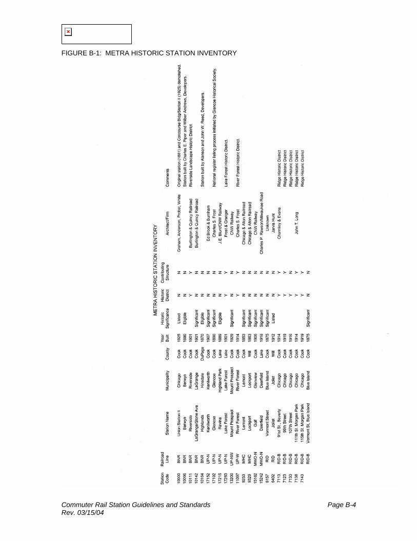
Commuter Rail Station Guidelines and Standards Page B-4 Rev. 03/15/04
FIGURE B-1: METRA HISTORIC STATION INVENTORY

Commuter Rail Station Guidelines and Standards Page B-5 Rev. 03/15/04
B.3 HISTORIC STATION NARRATIVE METRA BURLINGTON NORTHERN BERWYN: This Richardsonian depot is believed to have been designed and constructed by the Chicago Burlington and Quincy Railroad in 1890. The depot and rail service to Chicago had been requested by attorneys Charles E. Piper and Wilbur J. Andrews who were beginning to develop the community of Berwyn. The building was lengthened in 1917. It has been completely restored and is in very good condition. The building has been determined to be eligible for listing on the National Register of Historic Places. RIVERSIDE: This depot was designed by the engineering staff of the Chicago, Burlington and Quincy Railroad in 1901. The station is located in the Riverside Landscape Historic District and is listed as a contributing structure. The station complex consists of the depot with symmetrical canopy wings and porte-cochere entrance and an elaborate canopy with pavilion ends on the opposite platform. A tunnel, which is not currently used, connects the buildings. With the exception of the replacement of roof tile with asphalt shingles on the canopy opposite the depot, there have been no significant alterations. The buildings have been well maintained and are in good condition. STONE AVENUE, LAGRANGE: Designed by the engineering staff of the Chicago, Burlington and Quincy Railroad and erected in 1901, this depot was inspired by the Chicago and North Western Railway Kenilworth depot. Unlike Kenilworth, this depot is constructed of masonry. The style is definitely Richardsonian, although there are several concessions to the classical revivals which were popular at the time of the station's construction. The building has been very well maintained and is in very good condition. The building is a historically significant structure. HIGHLANDS, HINSDALE: Highlands was established as a flag stop in the early 1870's at the request of several local families. The depot was constructed a short time later. After the turn of the century, when the tracks were raised, a basement was constructed under the original building. The building is quite small and serves only as a waiting room. The building has recently been rehabilitated and is in very good condition. The building has been determined to be eligible for listing on the National Register of Historical Places. METRA UP-NORTH LINE KENILWORTH: This depot was designed in 1890 by the firm of Edbrooke and Burnham for the Chicago and North Western Railway. Although it initially appears to be a substantial Richardsonian stone structure, it is a wood frame building surrounded by a stone colonnade. Over the years, all of the original features have been retained and restored. The station is in excellent condition requiring only periodic maintenance. This is a historically significant structure. GLENCOE: Constructed in 1890, this brick depot is possibly the first that architect Charles S. Frost designed for the Chicago and North Western Railway. The style has been described as obscure northern
Commuter Rail Station Guidelines and Standards Page B-6 Rev. 03/15/04
rural French. The building has been well-maintained and the exterior remains unaltered. There is evidence of previous masonry replacement at the base of the exterior walls in addition to areas displaying substantial efflorescence. Both of these conditions are believed to be a result of deicing salt. The station is in excellent condition requiring only periodic maintenance. This is a historically significant structure and the National Register listing process has been initiated by the Glencoe Historical Society. RAVINIA: This frame depot was designed for the Chicago and North Western Railway by its chief engineer J.E. Blunt. It was constructed in 1889. The building has been determined to be eligible for listing on the National Register of Historic Places. The station is best described as a broad eaved shed executed in the Queen Anne style. The building has been completely restored and is in excellent condition. LAKE FOREST: This station is located in the Lake Forest Historic District and is listed as a contributing structure. It was designed in 1900 by the architectural firm of Frost and Granger and was constructed in 1901 by the Chicago and North Western Railway. It's design is similar to the large half-timbered Gothic residences which were popular at the time in the more affluent suburbs. The building has been restored, both interior and exterior. It is in excellent condition requiring only periodic maintenance. METRA UP-NORTHWEST LINE MOUNT PROSPECT: This stucco, brick and stone depot was designed in 1929 by the engineering staff of the Chicago and North Western Railway. This historically significant structure illustrates the mixture of Gothic and Georgian elements and is typical of the eclecticism of the 1920's. The station has been recently restored. The exterior has been returned to is original design. The interior has been remodeled, but does not change the character of the building. The building is in very good condition and should have a long service life with periodic maintenance. METRA UP-WEST LINE RIVER FOREST: This station is located in the River Forest Historic District. The depot was designed by architect Charles S. Frost for the Chicago and North Western Railway in 1914. The exposed concrete walls of the street level and half-timber design of the platform level are typical of the more utilitarian designs that Frost produced for the railroad. The upper level waiting room and agent's office is currently not accessible to the public. The lower level currently houses the offices of the River Forest Park District. The building has been designated as a contributing structure to the Historic District. The building is in good condition. METRA HERITAGE CORRIDOR LEMONT: This depot is the oldest depot in the Metra System and is historically significant. It was built by the Chicago and Alton Railroad and is believed to have been completed in 1853. The building type is commonly referred to as a broad eaved shed. It is constructed of locally quarried limestone, a common building material used during the nineteenth century. This station has been recently restored and is in excellent condition.
Commuter Rail Station Guidelines and Standards Page B-7 Rev. 03/15/04
LOCKPORT: This historically significant depot was constructed in 1863. The building is similar in construction to the neighboring Lemont Station. The building type is commonly referred to as a broad eaved shed. It is constructed of locally quarried limestone, a common building material used during the nineteenth century. An interior and exterior rehabilitation was completed in 1988. The building is in excellent condition. JOLIET: (See Rock Island District) MILWAUKEE DISTRICT – NORTH GOLF: This depot was designed by the engineering staff of the Chicago, Milwaukee and St. Paul Railway and constructed in 1906. This historically significant station is in need of restoration. The waiting room is in fair condition. The exterior is in poor condition. Immediate maintenance including painting and window repair or replacement should be initiated. Paving on both the street and platform sides has been elevated. The street side paving appears to be below the level of the foundation generally pitched away from the depot. The platform paving is at or above the level of the foundation and appears to be pitched to drain against the building. DEERFIELD: This historically significant depot was designed by Charles P. Rawson of the Chicago, Milwaukee, St. Paul and Pacific Railroad and built in 1918. The building has been recently renovated and is in very good condition requiring only periodic maintenance. ROCK ISLAND DISTRICT 91ST STREET, BEVERLY: This station is located in the Ridge Historic District and is a contributing structure. The depot was designed in the late 1890's by Charnley and Evans for the Chicago, Rock Island and Pacific Railway. The station is in good condition, requiring general maintenance only. 99TH STREET, BEVERLY: This station is located in the Ridge Historic District and is a contributing structure. It is believed to have been built in 1919. The heavy brackets supporting the eaves suggest a late Queen Anne design. The general condition is fair to poor and will require a moderate degree of maintenance and repair. 111TH STREET, MORGAN PARK: This station is located in the Ridge Historic District and is a contributing structure. This large Richardsonian depot was designed by architect John T. Long and constructed in 1914. The building is generally in good condition and should require only periodic contributing structure. The depot was constructed in 1919. The rounded corners and curved eaves relate the design to the American form of the Queen Anne known as the Shingle Style. The overall condition of the depot is fair to poor. Several sections of siding are severely deteriorated. The windows need to be replaced. The east elevation of the building has suffered damage as a result of the progressive raising of the platform which is now above the top of the foundation and paved against the wood siding.
Commuter Rail Station Guidelines and Standards Page B-8 Rev. 03/15/04
VERMONT STREET, BLUE ISLAND: This is the oldest surviving Chicago Rock Island and Pacific Railway depot in the Chicago area. Its building type is commonly referred to as a broad eaved shed and was built in 1875. A few changes have been made to the original structure, consisting of closing some door and window openings and reconstruction of the chimney. The window frames have been heavily painted which obscures their condition. The exterior masonry walls are covered by many layers of paint. The brickwork, which appears to be a variety of Chicago common, has suffered extensive deterioration at the base of the walls as a result of salt applications and freeze-thaw cycles. There are approximately thirty-five wood brackets which support the roof eaves and many of these need repair or replacement. The exterior of this depot is in very poor condition and should be given immediate repair and maintenance to slow deterioration until restoration efforts can be undertaken. JOLIET UNION STATION: This station is listed on the National Register of Historic Places. The depot is located where the tracks of the Chicago, Rock Island and Pacific Railway and the Atchison, Topeka and Santa Fe Railroad cross the former Chicago and Alton Railroad (now part of the Illinois Central Gulf Railroad). It was constructed as a union depot by all three railroads. It was designed in 1911 by architect Jarvis Hunt and constructed in 1912. Typical of major public buildings of the time, it was executed in a Beaux-Arts version of eighteenth century French Classicism. The waiting room has a large Baroque vaulted hall. This station is currently undergoing an extensive historic restoration.
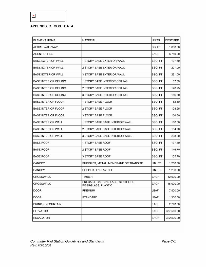
Commuter Rail Station Guidelines and Standards Page C-1 Rev. 03/15/04
APPENDIX C. COST DATA

Commuter Rail Station Guidelines and Standards Page C-2 Rev. 03/15/04
NOTE: Costs are in 2000 dollars.
APPENDIX C. COST DATA CONTINUED * * *
Commuter Rail Station Guidelines and Standards Page C-3 Rev. 03/15/04
NOTE: Costs are in 2000 dollars.

Commuter Rail Station Guidelines and Standards Page C-4 Rev. 03/15/04
APPENDIX C. COST DATA CONTINUED
NOTE: Costs are in 2000 dollars.

Commuter Rail Station Guidelines and Standards Page C-5 Rev. 03/15/04
APPENDIX C. COST DATA CONTINUED * * * NOTE: Costs are in 2000 dollars.
* Structure Elevation and Platform Elevation factors are applied based on type of structure (e.g. Structure improvements at street level = $10,000: same improvements on structure above street = $10,000 x 1.50 = $15,000).