Community and Renewable Energy Scheme Project Development ...
20
Community and Renewable Energy Scheme Project Development Toolkit Grid Connection Module
Transcript of Community and Renewable Energy Scheme Project Development ...
Community and Renewable Energy Scheme Project Development Toolkit Grid Connection Module
Developed by Ricardo Energy & Environment Revision 7 2
Module Structure
The CARES Project Development Toolkit is intended to be used as a reference by CARES clients of all
kinds, including community groups, community based businesses and rural businesses. This module
is one part of a series of documents forming the CARES Toolkit and is designed to cover all sizes of
project, although the scale and complexity of multi MW projects may require more detailed
evaluation than smaller projects. Other modules that may also be of particular interest to those
reading this module are as follows.
• establishing a community group
• project finance
• procurement
• securing the site
• planning
• grid connection
• the Feed-in-Tariff
• local energy supply
The Grid Connection Module is designed to cover all sizes of project and to assist community groups
of all kinds. Information specific to scale is flagged as appropriate. The module is divided into the
following sections:
The UK Electricity System – A brief overview of the electricity distribution system, designed to
support discussions that will be required during the connection process.
The Connection Process – An overview of the connection process for different sizes of generation.
The Cost of Connection – An overview of the components of and issues around connection charges.
Securing a Connection – Information about the content of connection offers, and the timescales
around receiving and accepting them.
Alternative Network Connections – The cost of connection can make a project unviable. There are
alternatives to the standard grid connection which can provide projects with additional revenue or
allow connections to be made under otherwise constrained conditions.
Further Information – Appropriate links to find more information.
Developed by Ricardo Energy & Environment Revision 7 3
The UK Electricity System
Electricity supply comprises two linked systems – transmission and distribution.
Electricity transmission transports electricity over long distances across the country. Electricity is
transported at a high voltage to reduce losses. In Scotland, the transmission network includes
network at 400kV, 275kV, and 132kV, and is owned and operated Transmission Owners (TOs)
Electricity distribution takes power from the transmission network and distributes it to consumers.
The voltage is reduced to the correct supply voltage for the loads. In England and Wales, these
networks operate at 132kV and lower. Most residential customers are supplied at 230V. These
networks are owned and operated by licenced Distribution Network Operators (DNOs) who are each
responsible for the network within a geographic area.
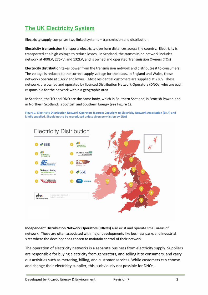
In Scotland, the TO and DNO are the same body, which in Southern Scotland, is Scottish Power, and
in Northern Scotland, is Scottish and Southern Energy (see Figure 1).
Figure 1: Electricity Distribution Network Operators (Source: Copyright to Electricity Network Association (ENA) and kindly supplied. Should not to be reproduced unless given permission by ENA)
Independent Distribution Network Operators (IDNOs) also exist and operate small areas of
network. These are often associated with major developments like business parks and industrial
sites where the developer has chosen to maintain control of their network.
The operation of electricity networks is a separate business from electricity supply. Suppliers
are responsible for buying electricity from generators, and selling it to consumers, and carry
out activities such as metering, billing, and customer services. While customers can choose
and change their electricity supplier, this is obviously not possible for DNOs.

Developed by Ricardo Energy & Environment Revision 7 4
In a traditional power system, large power stations feed into the transmission network, and the
electricity is then transported to the distribution Networks. The distribution networks carry the
electricity to loads, such as homes and businesses. The transmission and distribution networks are
also called transmission and distribution systems.
However, an increasing number of small power stations are being developed, often connected to
distribution networks. Generation connected to the distribution network is called Distributed
Generation (or Embedded Generation). Distributed Generation can result in electricity flows in both
directions; from the distribution network to customers, and from customers with Distributed
Generation back into the distribution network. The system is no longer a “waterfall” system, with
electricity flowing from the large power stations in one direction towards customers. Instead,
electricity flows are more unpredictable.
This Guide is aimed at community renewable energy schemes to be connected to the distribution
network. Therefore it will be your DNO who is you main point of contact for connection. However,
there can also be constraints at the transmission network level which can affect the operation of
embedded generation projects.
Figure 2: An example of a typical generation connection
The Connection Process – Embedded Generation
A number of technical standards are in place to govern the requirements for grid connection. These
standards serve several purposes, including:
• to ensure that the generator will be able to operate safely on the network, and will not cause any
issues with network protection or power quality (such as voltage level and frequency), and
• to protect the generator from any faults that may occur on the distribution network.
In the diagram below, the generation is connected to the DNO network via a network extension, and the local
substation also needs to be reinforced (for example with a larger transformer). Note that in some cases, equipment
further up the network may also need to be reinforced.
Developed by Ricardo Energy & Environment Revision 7 5
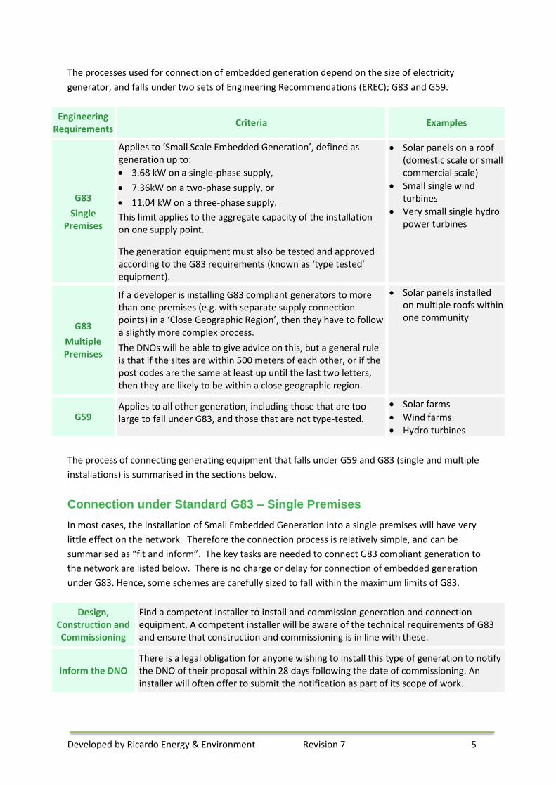
The processes used for connection of embedded generation depend on the size of electricity
generator, and falls under two sets of Engineering Recommendations (EREC); G83 and G59.
Engineering Requirements
Criteria Examples
G83
Single Premises
Applies to ‘Small Scale Embedded Generation’, defined as generation up to:
• 3.68 kW on a single-phase supply,
• 7.36kW on a two-phase supply, or
• 11.04 kW on a three-phase supply.
This limit applies to the aggregate capacity of the installation on one supply point.
The generation equipment must also be tested and approved according to the G83 requirements (known as ‘type tested’ equipment).
• Solar panels on a roof (domestic scale or small commercial scale)
• Small single wind turbines
• Very small single hydro power turbines
G83
Multiple Premises
If a developer is installing G83 compliant generators to more than one premises (e.g. with separate supply connection points) in a ‘Close Geographic Region’, then they have to follow a slightly more complex process.
The DNOs will be able to give advice on this, but a general rule is that if the sites are within 500 meters of each other, or if the post codes are the same at least up until the last two letters, then they are likely to be within a close geographic region.
• Solar panels installed on multiple roofs within one community
G59 Applies to all other generation, including those that are too large to fall under G83, and those that are not type-tested.
• Solar farms
• Wind farms
• Hydro turbines
The process of connecting generating equipment that falls under G59 and G83 (single and multiple
installations) is summarised in the sections below.
Connection under Standard G83 – Single Premises
In most cases, the installation of Small Embedded Generation into a single premises will have very
little effect on the network. Therefore the connection process is relatively simple, and can be
summarised as “fit and inform”. The key tasks are needed to connect G83 compliant generation to
the network are listed below. There is no charge or delay for connection of embedded generation
under G83. Hence, some schemes are carefully sized to fall within the maximum limits of G83.
Design, Construction and Commissioning
Find a competent installer to install and commission generation and connection equipment. A competent installer will be aware of the technical requirements of G83 and ensure that construction and commissioning is in line with these.
Inform the DNO There is a legal obligation for anyone wishing to install this type of generation to notify the DNO of their proposal within 28 days following the date of commissioning. An installer will often offer to submit the notification as part of its scope of work.
Developed by Ricardo Energy & Environment Revision 7 6
Ongoing Responsibilities
The equipment needs to be maintained throughout its lifetime to ensure that it is in good working order and continues to meet the requirements of G83.
Connection under Standard G83 – Multiple Premises
Where customers, developers or installers wish to install more than one G83 unit within a close
geographic region, there is a much greater chance that the connected generation will have an
impact on the local network. DNOs may have to upgrade existing equipment, or install new
equipment, to ensure that the network can maintain proper operation when the generation comes
online. Therefore an agreement must be made with the DNO before the connection is made, and
the generation developer will be pay a connection charge to cover the cost to the DNO.
The list below presents the key actions that you have to complete to connect multiple to the
electricity distribution network. This is alongside the other elements of the project such as design
and construction of the installation itself, and any commercial arrangements to sell the electricity
that the system will produce.
Review Information and Discuss with the
DNO
DNOs provide information to support generation developers on their websites, such as maps that show the existing spare network capacity. Many also hold dedicated generation ‘surgeries’ or ‘drop in’ sessions to discuss projects.
Early engagement with the DNOs is important to identify any potential grid connection barriers to the project. This is important to ensure grid connection timelines and costs are commensurate with project ambitions. See the Further Information section for links to the DNO websites.
Formal Application and
Connection Offer
Before the connection to the network is constructed, a formal connection offer must be agreed with the DNO. To do this, an application form must be submitted in the format given in Appendix 2 of EREC G83, which is available on the Energy Network Association’s website. The form is often submitted by the installer.
Once the DNO has reviewed the form and conducted any assessments, they will produce a connection offer. This will specify the conditions for the connection and any connection charges that apply. You should ensure that you fully understand this offer before accepting it, and can discuss questions with your DNO if you are unsure.
Construction and Commissioning
The DNO may need to carry out some work to prepare for the connection, for example to increase the capacity of the local network to ensure that your generation can connect safely. Close communication with the DNO throughout this process will allow coordinated planning of construction and connection.
Again, a competent installer should be aware of the technical requirements of G83 and ensure that construction and commissioning is in line with these.
Inform the DNO
Once the installation is complete, the DNO needs to be made aware of your generating unit(s) and the technical detail of the installation. An installation commissioning confirmation form must be submitted for each installation within 28 days of commissioning. This is usually completed by the installer.
Ongoing Responsibilities
The equipment needs to be maintained throughout its lifetime to ensure that it is in good working order and continues to meet the requirements of G83. The DNO must be
Developed by Ricardo Energy & Environment Revision 7 7
informed if any change is made to the generation or connection equipment, and when the equipment is decommissioned.
Connection under Standard G59
The tasks for connecting generation equipment under G59 are similar to those to connect multiple
generators under G83, in that there needs to be a connection agreement with the DNO before the
connection is made. However, the process is potentially more complex, and the cost of connection
could be significantly higher if the infrastructure and planning required to make the connection may
be much greater. The list below presents the key actions that you have to complete to connect
multiple generators to the electricity distribution network.
Review Information and Discuss with the
DNO
Use the information provided by the DNOs during the design of your project. For example, their Long Term Development Statements which will lay out the plans that they have to develop their networks in the future, and network capacity information including capacity heat maps. Many also hold dedicated generation ‘surgeries’ or ‘drop in’ sessions to discuss projects.
Early engagement with the DNOs is important to identify any potential grid connection barriers to the project. This is important to ensure grid connection timelines and costs are commensurate with project ambitions.
Gain Information and Plan Provision
of Connection
Seek initial meetings with the DNO to discuss the proposed generation project, discuss the process of connection, and clarify the contestable and non-contestable work required for the connection.
Non-Contestable Work: The tasks that DNOs must do themselves, so that they can maintain co-ordination and control of their networks. Generally this includes reinforcing existing network equipment.
Contestable Work: The work that is open to competition it is called Contestable work, and can be conducted by the DNO or Independent Connections Providers (ICPs). This will be an individual project decision. Often, this work includes installation of new infrastructure, such as cables, transformers etc., that do not yet exist on the network.
Formal Application and
Agreements
Connection Application: All DNOs use the same common application form for G59 connection applications, and the DNO will specify what information they need. There is also a simplified form specifically for smaller generation projects (50kW or less three phase, or 17kW or less single phase), which is type tested under G59 or G83. This form may be submitted by the developer, installer, or the ICP.
Connection Agreement: Once the DNO has reviewed the form and conducted any assessments, they will produce a connection offer. This will specify the conditions for the connection and any connection charges that apply. You should ensure that you fully understand this offer before accepting it, and can discuss questions with your DNO if you are unsure.
Adoption Agreement: Where an ICP has been used to construct some of the connection infrastructure, an Adoption Agreement may be necessary to lay out the terms under which the DNO will take ownership of these connection assets.
Site Responsibility Schedule: (sometimes called a Joint Operational Agreement) In some cases it will be necessary to have a formal agreement for the operation of the connection interface between the generation project and the distribution network.
Developed by Ricardo Energy & Environment Revision 7 8
Construction
Clear communication is essential between the developer, the DNO and the ICP (where applicable) in order to coordinate construction of the generation equipment itself and the construction of the connection infrastructure.
Once the equipment is constructed, the final generation equipment parameters will need to be submitted to the DNO. Where this is different to those supplied before the connection offer, then the DNO may need to review the offer.
Commissioning
Clear communication is also required during planning and carrying out the commissioning and connection, as both the generation unit and the connection equipment will need to be ready for the connection to be made.
The generation equipment will need to be commissioned according to the requirements of G59, and the DNO may need to witness this. You must inform the DNO of the proposed commissioning schedule at least 15 working days before the intended date.
After commissioning, a Commissioning Form will need to be submitted to the DNO. This must be within 30 days of commissioning.
Ongoing Responsibilities
The equipment needs to be maintained throughout its lifetime to ensure that it is in good working order and continues to meet the requirements of G59. The DNO must be informed if any change is made to the generation or connection equipment, and when the equipment is decommissioned.
Generation Embedded within a Building’s Electrical System
If the proposed installation is to be connected to the system after the fuse protecting the DNO
electricity supply and there is no intention to export electricity to the grid, then a connection
agreement is not required. Under these circumstances, you must put the appropriate technology in
place to prevent overspill of electricity on to the grid. Again, all work should be carried out to the
necessary health and safety requirements and wiring regulations. Such detailed evaluation of the
electrical systems should be completed by a qualified electrical engineer and is likely to form part of
the technology supply agreements.
The Cost of Connection
The cost of connection charged by a DNO will include a number of elements. The most obvious
element is the cost of the infrastructure to connect the generation unit. This is made up of:
• Network Extension – the cost of any new infrastructure built to connect the generation project to
the network will be charged to the developer through the connection charge.
• Network Reinforcement – a proportion of any infrastructure associated with reinforcement of
existing network will be charged to the developer through the connection charge.
The connection charge will also include other elements, such as the cost of any investigations and
studies carried out in order to deliver the connection offer, site visits and administration.
DNOs publish information on how they determine connection charges (often called ‘charging
methodologies’), and these can be used to gain an idea of the likely charges that will be included
before the formal offer is made. This information will be on the DNOs’ websites.
Developed by Ricardo Energy & Environment Revision 7 9
Budget or indicative estimates for connection charges may be gained by a DNO or third party
consultants, though these should be interpreted carefully as they may not be accurate. While DNOs
cannot charge when giving formal quotes, some may charge to give estimates.
In some cases, the planned generation will impact the transmission network, and additional studies
will need to be carried out by the Transmission System Operator, National Grid. This is known as the
Statement of Works process, and is more likely where the generation is larger, though it may apply
to even smaller generation under certain circumstances. The DNO will interface with National Grid
to carry out this process, but it may have a significant impact on the cost of connection.
Grid connection costs can range from £100,000/MW to £1,700,000/MW. In addition, it should be
noted that the initial cost of connection identified at the feasibility stage can vary significantly from
the final cost of the connection. See Further Information for more examples of connection costs.
Securing a Connection
Available capacity and connection capability on the network is a limited resource, and is sometimes
in high demand from developers. Therefore, if you are developing projects under G59 or G83
Multiple Premises, then it is a good idea to secure an agreement quickly.
Accepting Connection Offers
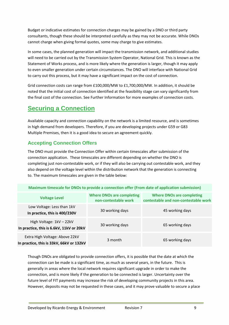
The DNO must provide the Connection Offer within certain timescales after submission of the
connection application. These timescales are different depending on whether the DNO is
completing just non-contestable work, or if they will also be carrying out contestable work, and they
also depend on the voltage level within the distribution network that the generation is connecting
to. The maximum timescales are given in the table below:
Maximum timescale for DNOs to provide a connection offer (From date of application submission)
Voltage Level Where DNOs are completing
non-contestable work Where DNOs are completing
contestable and non-contestable work
Low Voltage: Less than 1kV
In practice, this is 400/230V 30 working days 45 working days
High Voltage: 1kV – 22kV
In practice, this is 6.6kV, 11kV or 20kV 30 working days 65 working days
Extra High Voltage: Above 22kV
In practice, this is 33kV, 66kV or 132kV 3 month 65 working days
Though DNOs are obligated to provide connection offers, it is possible that the date at which the
connection can be made is a significant time, as much as several years, in the future. This is
generally in areas where the local network requires significant upgrade in order to make the
connection, and is more likely if the generation to be connected is larger. Uncertainty over the
future level of FIT payments may increase the risk of developing community projects in this area.
However, deposits may not be requested in these cases, and it may prove valuable to secure a place

Developed by Ricardo Energy & Environment Revision 7 10
in the queue as circumstances may change, for example if other planned projects do not go ahead,
or if changes in regulations or technology allow more generators to connect.
Constrained Connection Agreements
In most cases, to provide a connection offer, the DNO has to take into account all of the worst-case
conditions that could occur, and will design the connection so that the generation can output at full
capacity under all normal network circumstances. This can lead to high costs of connection.
It may also be possible for generators in areas of grid capacity constraint to enter into connection
agreements that are constrained according to a specific set of circumstances. This is sometimes
called a ‘non-firm’ connection agreement. A connection may be possible, in return for agreement
that the DNO may need to restrict or switch off the generator. Such agreements can be useful to
allow generators to connect to heavily congested networks without needing to pay very large
connection charges, but the conditions will introduce additional risk and uncertainty in predicting
revenue.
It should be noted that even with a standard connection agreement, in very rare cases the DNO may
need to curtail generation in order to ensure safe operation of the network or to maintain power
quality.
Accepting a Connection Offer
Once the offer is issued by the DNO, you have a limited time in which to respond, generally between
30 and 90 days. Once this time is over, then there is no guarantee that the offer can be made in the
same terms again, for example if the conditions on the network have changed, or the available
capacity has been assigned to another application.
Since obtaining a grid connection is required to pre-accredit for the Feed-in Tariff (FIT) and to secure
financial close, the connection application must usually be made at risk, in advance of funding being
available. This makes it essential to identify a source of any deposit prior deciding to secure a
connection. The deposit can be as much as 25% of the cost of the non-contestable works. This is
often negotiable with the DNO.
In some cases it will be possible for multiple connection applications to affect each other, for
example if they are connecting to the same area of network with limited available capacity. These
applications are generally classed as ‘interactive’ and can be subject to a set process. In this process,
the applications are considered in the order that they were received, and parties are each given an
opportunity to accept the offer. Therefore, if you think your project may become interactive, it is
important to submit your connection application as soon as you can. The DNO will inform all parties
if their connection offer is, or becomes, interactive, and will explain their place in the queue and the
process of accepting interactive offers.
It should be noted that connection offers can be withdrawn if the project is not progressing with
reasonable pace. This is so that the network capacity is not set aside for projects that are not going
ahead, and to allow other projects to use that capacity. The DNO may specify milestones in their
connection offer that the project must meet in order to keep the agreement.

Developed by Ricardo Energy & Environment Revision 7 11
Wayleaves and Consents
Where possible, the DNO will design any infrastructure routes so that they lie either within the
boundary of your land, or on land that they have control over, avoiding the need for third-party
agreement. If this is not possible, then an agreement will need to be reached with all land owners
along the proposed connection route.
DNOs will require the consent of the landowner prior to beginning any work – consent is normally
granted via a wayleave or servitude. This can affect the quotation offer and lead times required to
complete the work. Early engagement with all parties is essential to identify any potential barriers to
grid connection.
You will have to take the following into consideration when planning your project:
• timescales associated with obtaining third-party agreement can affect your project's delivery
timetable;
• DNOs do not seek such consents until you have accepted their quotation;
• the charges given on quotations are given subject to all consents being agreed;
• where consents are refused, a new design and quotation will be required; and
• DNOs cannot undertake any works on third-party land until all consents have been agreed.
Legal advice on securing consent from other landowners is recommended.
Preparing for Financial Close
All information relating to the grid connection should be held securely in a central location. Potential
lenders will want to see this information. Securing a grid connection is a key requirement before
lenders will fund a project. Showing progress in securing the grid connection is important in the early
stages of engaging with a lender
Alternative network connections
The standard process for connecting generation equipment to the local electricity network outlined
above has been designed to preserve the safety and security of the supply, while allowing
generation to connect.
While the DNO cannot refuse connection to their network, it is possible that the connection offer
issued will give very high connection cost values, or may not allow connection for a number of years.
It is therefore not uncommon for projects to be made unviable based on these restrictions. Because
of this, it is sometimes necessary to seek alternative technical models to build a successful project.
Non-Traditional Network Connections
As discussed above, where a connection offer contains high connection costs and a long lead time,
this is generally as a result of reinforcement required to the network, which is needed to
accommodate the new generation on the network.
Depending on the particular issue, a possible alternative to reinforcement is to enter into a non-
traditional connection agreement with the DNO. A Flexible Connection Offer may be issued, for
example, where the DNO sets a maximum level for export, or restricts generation export under
Developed by Ricardo Energy & Environment Revision 7 12
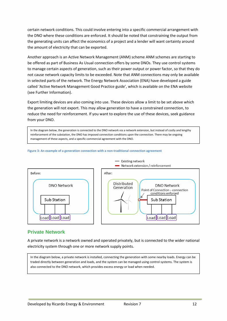
certain network conditions. This could involve entering into a specific commercial arrangement with
the DNO where these conditions are enforced. It should be noted that constraining the output from
the generating units can affect the economics of a project and a lender will want certainty around
the amount of electricity that can be exported.
Another approach is an Active Network Management (ANM) scheme ANM schemes are starting to
be offered as part of Business As Usual connection offers by some DNOs. They use control systems
to manage certain aspects of generation, such as their power output or power factor, so that they do
not cause network capacity limits to be exceeded. Note that ANM connections may only be available
in selected parts of the network. The Energy Network Association (ENA) have developed a guide
called ‘Active Network Management Good Practice guide’, which is available on the ENA website
(see Further Information).
Export limiting devices are also coming into use. These devices allow a limit to be set above which
the generation will not export. This may allow generation to have a constrained connection, to
reduce the need for reinforcement. If you want to explore the use of these devices, seek guidance
from your DNO.
Figure 3: An example of a generation connection with a non-traditional connection agreement
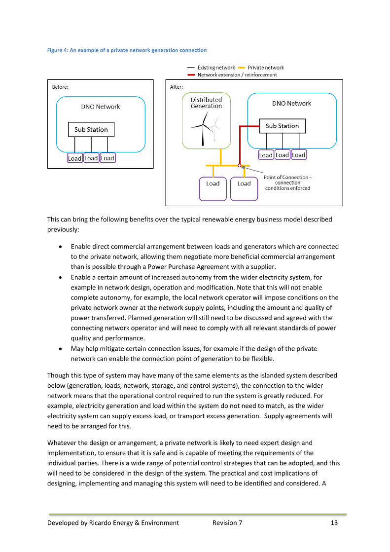
Private Network
A private network is a network owned and operated privately, but is connected to the wider national
electricity system through one or more network supply points.
In the diagram below, the generation is connected to the DNO network via a network extension, but instead of costly and lengthy
reinforcement of the substation, the DNO has imposed connection conditions upon the connection. There may be ongoing
management of these aspects, and a specific commercial agreement with the DNO.
In the diagram below, a private network is installed, connecting the generation with some nearby loads. Energy can be
traded directly between generation and loads, and the system can be managed using control systems. The system is
also connected to the DNO network, which provides excess energy or load when needed.
Developed by Ricardo Energy & Environment Revision 7 13
Figure 4: An example of a private network generation connection
This can bring the following benefits over the typical renewable energy business model described
previously:
• Enable direct commercial arrangement between loads and generators which are connected
to the private network, allowing them negotiate more beneficial commercial arrangement
than is possible through a Power Purchase Agreement with a supplier.
• Enable a certain amount of increased autonomy from the wider electricity system, for
example in network design, operation and modification. Note that this will not enable
complete autonomy, for example, the local network operator will impose conditions on the
private network owner at the network supply points, including the amount and quality of
power transferred. Planned generation will still need to be discussed and agreed with the
connecting network operator and will need to comply with all relevant standards of power
quality and performance.
• May help mitigate certain connection issues, for example if the design of the private
network can enable the connection point of generation to be flexible.
Though this type of system may have many of the same elements as the Islanded system described
below (generation, loads, network, storage, and control systems), the connection to the wider
network means that the operational control required to run the system is greatly reduced. For
example, electricity generation and load within the system do not need to match, as the wider
electricity system can supply excess load, or transport excess generation. Supply agreements will
need to be arranged for this.
Whatever the design or arrangement, a private network is likely to need expert design and
implementation, to ensure that it is safe and is capable of meeting the requirements of the
individual parties. There is a wide range of potential control strategies that can be adopted, and this
will need to be considered in the design of the system. The practical and cost implications of
designing, implementing and managing this system will need to be identified and considered. A
Developed by Ricardo Energy & Environment Revision 7 14
private wire solution is often implemented by local authorities via an Energy Services Company
(ESCO).
Below are some examples of private networks:
• Electricity networks on private land, for example many university campuses are examples of
this; and
• Networks connecting generation and load in order to enable easier direct trading between
the two, for example, Woking private network.
Island Systems
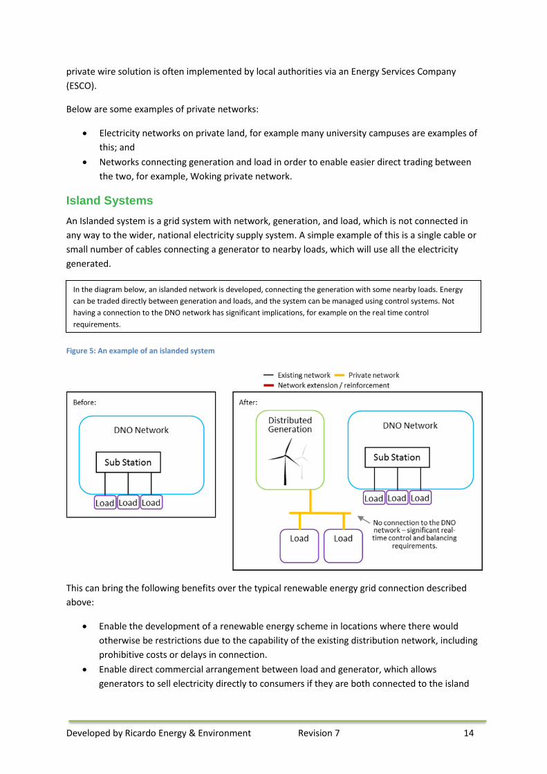
An Islanded system is a grid system with network, generation, and load, which is not connected in
any way to the wider, national electricity supply system. A simple example of this is a single cable or
small number of cables connecting a generator to nearby loads, which will use all the electricity
generated.
Figure 5: An example of an islanded system
This can bring the following benefits over the typical renewable energy grid connection described
above:
• Enable the development of a renewable energy scheme in locations where there would
otherwise be restrictions due to the capability of the existing distribution network, including
prohibitive costs or delays in connection.
• Enable direct commercial arrangement between load and generator, which allows
generators to sell electricity directly to consumers if they are both connected to the island
In the diagram below, an islanded network is developed, connecting the generation with some nearby loads. Energy
can be traded directly between generation and loads, and the system can be managed using control systems. Not
having a connection to the DNO network has significant implications, for example on the real time control
requirements.
Developed by Ricardo Energy & Environment Revision 7 15
network, and so potentially benefit from a higher generation tariff than selling through a
Power Purchase Agreement with a supplier.
• Enable autonomy from the wider electricity system and its restrictions.
The key disadvantage of this kind of system is that it cannot rely on a wider grid to supply excess
load that is not covered by generation, or to take excess generation that is not used by the loads.
The impact of this is that there is a need to develop and operate a much more complex system,
involving generation, network, loads, and control systems. There are a number of key aspects that
will need to be considered when deciding if this is the best option for a particular project, including:
• Location of Generation and Load – What is the location of the loads to be supplied
compared to the generation site? The closer the two are together, the shorter the network
routes are likely to be.
• Ownership and Accessibility of Route – Negotiating access and use of land for routing
networks (wayleaves) can be complex, particularly if the route crosses many different land
ownership boundaries, or if it needs to cross or run near to public roads.
• Matching the size of Generation and Load – In a system that is not connected to the wider
electricity system, the energy generation and energy requirements of the load will need to
be closely matched.
• Power Profiles – The amount of power required by the load may vary over time, and this
varying power profile will need to be supplied by the system. It is possible that the
generation output will be sufficiently controllable to supply this power profile. However,
where the output of the generation is not sufficiently controllable (for example solar or wind
generation) then additional equipment may be needed, for example energy storage.
• Power Quality – Electricity supplied from distribution networks from the national grid is
controlled to ensure that certain aspects are suitable for use in connected appliances. These
aspects include frequency and voltage. In an islanded system, there is no such guarantee of
power quality. It is important that the actual power quality requirements of the loads are
identified so that the system can be designed to meet them.
Whatever the design or arrangement, an islanded system is likely to need a significant amount of
expert design and operation, to ensure that it is safe and is capable of meeting the requirements of
the individual parties. Control systems will be required to ensure that the power demand of the
loads is matched by the power output by generation and/or storage. The practical and cost
implications of designing and operating this system will need to be identified and considered.
Generally, island electricity systems are used to provide an electricity supply to an area that cannot
be supplied (either practically or economically) with a larger electricity system. For example:
• Geographical islands, for example Fair Isle and the Isle of Rùm in Scotland;
• Extremely remote locations; and
• Rural or remote electrification in developing countries, which is used where a country’s
electricity system is not developed enough to cover the whole population.
Island systems are not often a suitable solution for small scale renewable generation development,
due to the significant technical and logistical requirements to successfully design, implement and
operate them, and the costs associated with this.
Developed by Ricardo Energy & Environment Revision 7 16
Microgrids
True Microgrids are networks that connect generation and load, and are capable of being run both
connected to, or isolated from, the wider electricity system. This brings the advantages of being
connected to the wider system, which provides excess energy or load as it is needed, but it also has
the capability of improving security of supply – when problems occur in the main grid, the microgrid
can disconnect and continue to operate.
However, the technical requirements of such a system are even more comprehensive than those for
an island system. This is because as well as being able to run islanded, the microgrid must be able to
make the connection with the wider system, which requires specialist equipment and design.
Examples of a microgrid system are:
• Tohoku Fukushi University (Japan), developed for security of supply; and
• Santa Rita Jail (USA), developed to provide a more economical energy trading opportunity,
and also for security of supply.
As with island systems, true microgrid systems are not often a suitable solution for small scale
renewable generation development, due to the significant technical and logistical requirements to
successfully design, implement and operate them, and the costs associated with this.
A user guide to the issues and value of microgrids has been made available by Highlands and Islands
Enterprise (HIE) and Scottish Government. The aim is to assist in the understanding of microgrids,
their issues and value. The scope is to provide sufficient context as to what constitutes a microgrid,
set out key issues and identify the advantages and disadvantages of microgrids. See ‘Further
Information’ for further information.
Developed by Ricardo Energy & Environment Revision 7 17
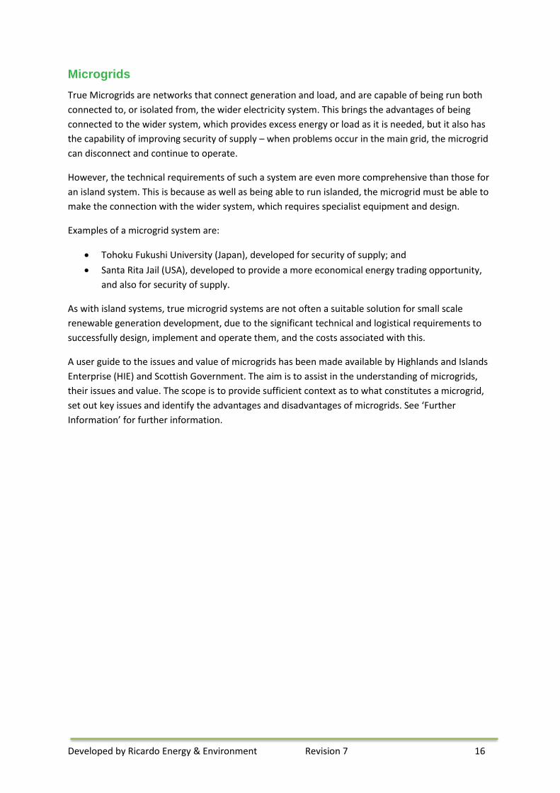
Business model comparison
The table below compares the four business models described above.
Description Pros Cons Typical Generation Connection
A standard connection application form is sent to the DNO, and they respond with a connection offer.
Standard procedure that is well developed.
The need to reinforce the network may bring significant costs and time delays. Energy cannot be easily traded between small scale generation and load unless you have a supply licence.
Non-Traditional Network Connection
The generator and the DNO enter into an agreement for a flexible connection. A proportion of the reinforcement cost is avoided by the connection being constrained within certain operating conditions.
A proportion of reinforcement costs and time delays may be avoided.
Connection restrictions may negatively impact the business case of the project. Energy cannot be easily traded between small scale generation and load unless you have a supply licence.
Private Networks
A private network is installed, for example connecting generation with nearby loads. This network is connected to the wider DNO network, which will provide additional energy or load when needed.
Energy can be more easily traded between generation and loads connected to the private network. A proportion of reinforcement costs and time delays may be avoided through careful design.
Connection to the DNO network will impose restrictions in the connection point, which may impact the business case for the project. Reinforcement may still be necessary, with the associated costs and time implications. There is likely to be an increased cost implication of a private network when compared to a typical connection.
Islanded System
An island network is installed, for example connecting generation with nearby loads. This network is not connected to the wider DNO network. This means that generation and demand will need to be balanced in real time on the network, and the power quality will need to be managed.
Energy can be more easily traded between generation and loads connected to the private network. No DNO network reinforcement costs will be incurred. Autonomy from the wider network means that certain restrictions, e.g. on power quality, may not have to be met.
There are significant control implications associated with this solution, with the associated cost and logistical arrangements. Safety and power quality will need to be managed. There is likely to be a significant cost associated with the setup of an island network when compared to a typical connection.
Supporting Technologies
Smart grid technologies
‘Smart grid’ is a term used a lot in the energy industry, and is generally used to describe a grid and
system with the capability to monitor, operate, and control system elements in such a way as to
Developed by Ricardo Energy & Environment Revision 7 18
optimise operation. It may include elements such as smart meters, smart appliances, renewable
energy resources, energy efficiency technologies and communications between devices.
Though smart grids are often talked about as part of the wider electricity network, they can be used
on a smaller scale as well. For example, islanded systems and private networks may use them as an
essential way of operating the network efficiently and effectively.
Some of the most relevant Smart Grid strategies include:
• Real Time Monitoring and Control – A key element of Smart Grids is the capability to
understand what is happening within the network in real time, and to make an impact on its
operation. This is vital in an Islanded system, which will need to be controlled and balanced
in real time. This necessitates components such as sensors to capture data, analysis
capability, and some controllable element within the network, for example to control the
settings of assets such as transformers and switches. In many cases, particularly for larger
networks, this may be partly or completely automated, and will be controlled by an
automated control system.
• Demand Side Management – It is vital that generation and load are balanced in real time.
Traditionally, this is done by controlling the generation to match demand, which has been
possible due to the fact that most of the generation is highly controllable. However, in an
islanded system, the generation source may not be controllable (for example, where the
generation relies on uncontrollable renewable energy sources such as solar and wind), or
there may be certain restrictions such as peak output.
Demand Side Management enables the demand to be varied to match the generation. This
is carried out using smart appliances and controllable loads, which are responding to the
requirements of the network. In practice, balancing may be achieved through a mixture of
generation output control and Demand Side Management.
Storage
The key advantage of incorporating energy storage into a network is to enable excess generation to
be stored for future use by the load. This means that there is more flexibility in the timing of
generation profiles and load profiles. The integration of storage technologies with renewable
generation is still an innovative approach to the design of renewable systems, so will be considered
as such by any potential lenders, potentially requiring additional technical due diligence before any
finance would be provided.
Electricity storage can take many forms, including:
• Electrochemical storage in batteries, which are generally built using three basic components
– anode, cathode and electrolyte. Batteries are capable of multiple charge and discharge
cycles and are modular which means that they can be readily combined to create large scale
battery storage systems if required. The main advantages are that they are a low capital cost
solution (in comparison with other storage) and have high power and energy density, which
means that they do not take up a large footprint. Additionally, batteries can store electricity
over a long duration but can only typically discharge for up to a matter of hours at a time.

Developed by Ricardo Energy & Environment Revision 7 19
• Flywheels, which are a form of mechanical storage which use the rotation of a mass to store
energy. Flywheels can store energy from both electrical and mechanical sources, making
them flexible as energy storage devices. They typically operate in a vacuum, which means
the storage duration is very long. The benefits of flywheels are their rapid response and high
efficiency, but they can only deliver energy over a short duration.
• Hydrogen (created through electrolysis using excess electricity). Hydrogen has the highest
energy to weight ratio of all conventional fuels, almost double that of natural gas and
gasoline. However, it has a low energy to volume ratio. Some of the major benefits of
hydrogen are that it can be combusted to produce heat and steam or it can produce
electricity when combined with oxygen in a fuel cell. In this way, hydrogen has applications
in the electricity, heating and transportation sectors. However, hydrogen is difficult to store
due to its nature and as such storage is a large cost barrier for this technology if it cannot be
used imminently. Using excess electricity to generate hydrogen through electrolysis is
relatively immature, but there are a number of pilot projects which are investigating the
feasibility and costs of this solution.
• Ammonia; Ammonia is a compound of hydrogen and nitrogen which is a colourless gas that
has a characteristic sharp smell. As a result of its chemical composition, it contains more
hydrogen than pressurised or liquefied pure hydrogen and is therefore a good candidate for
a hydrogen carrier and fuel. As such, it can be used in much the same way as described for
hydrogen above with the added benefit that storage of ammonia is much less costly than
hydrogen as it is easily liquefied and stored in inexpensive and low pressure containers.
• Electricity can also be stored as heat in what is termed Pumped Heat Electrical Storage
(PHES), where the electricity is used to drive a heat pump connected to two large thermal
stores. The system operates by pumping heat from a ‘cold store’ to a ‘hot store’, in much the
same way as a fridge, to store electricity. The heat pump can be reversed to become a heat
engine to generate electricity via a generator. This solution is low cost however it is still in its
infancy. If combined with a heat network excess electricity can also be stored as hot water.
Developed by Ricardo Energy & Environment Revision 7 20
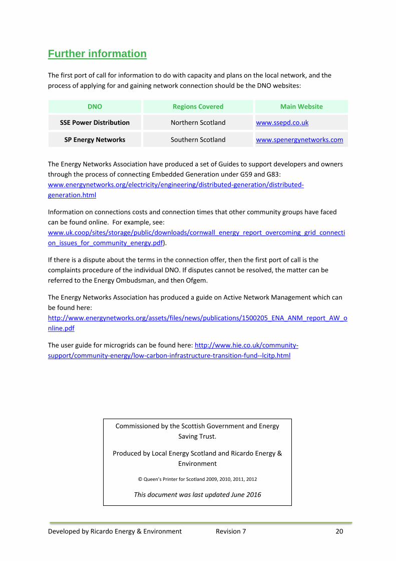
Further information
The first port of call for information to do with capacity and plans on the local network, and the
process of applying for and gaining network connection should be the DNO websites:
DNO Regions Covered Main Website
SSE Power Distribution Northern Scotland www.ssepd.co.uk
SP Energy Networks Southern Scotland www.spenergynetworks.com
The Energy Networks Association have produced a set of Guides to support developers and owners
through the process of connecting Embedded Generation under G59 and G83:
www.energynetworks.org/electricity/engineering/distributed-generation/distributed-
generation.html
Information on connections costs and connection times that other community groups have faced
can be found online. For example, see:
www.uk.coop/sites/storage/public/downloads/cornwall_energy_report_overcoming_grid_connecti
on_issues_for_community_energy.pdf).
If there is a dispute about the terms in the connection offer, then the first port of call is the
complaints procedure of the individual DNO. If disputes cannot be resolved, the matter can be
referred to the Energy Ombudsman, and then Ofgem.
The Energy Networks Association has produced a guide on Active Network Management which can
be found here:
http://www.energynetworks.org/assets/files/news/publications/1500205_ENA_ANM_report_AW_o
nline.pdf
The user guide for microgrids can be found here: http://www.hie.co.uk/community-
support/community-energy/low-carbon-infrastructure-transition-fund--lcitp.html
Commissioned by the Scottish Government and Energy
Saving Trust.
Produced by Local Energy Scotland and Ricardo Energy &
Environment
© Queen’s Printer for Scotland 2009, 2010, 2011, 2012
This document was last updated June 2016