Communications Technology Lecture 6: Data Link Layer June 2009.
99
Communications Technology Lecture 6: Data Link Layer June 2009
-
Upload
bridget-coleen-porter -
Category
Documents
-
view
214 -
download
0
Transcript of Communications Technology Lecture 6: Data Link Layer June 2009.

Communications Technology
Lecture 6: Data Link Layer
June 2009

References
Computer Network by A. S. Tanenbaum, Chapter 3
Data & Computer Communications by William Stallings
Understand principles behind data link layer services: error detection, correction sharing a broadcast channel:
multiple access MAC protocols
continued
Learning Objectives

Data Link Layer (L2)
Introduction and services Error detection and correction Multiple/Media access protocols

L2 IntroductionSome terminologies hosts and routers are nodes communication channels
that connect adjacent nodes along communication path are links
wired links wireless links LANs
layer-2 packet is a frame, encapsulates datagram
“link”
data-link layer has responsibility of transferring datagram from one node to adjacent node over a link
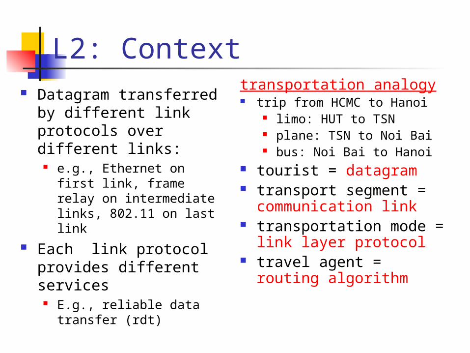
L2: Context Datagram transferred
by different link protocols over different links:
e.g., Ethernet on first link, frame relay on intermediate links, 802.11 on last link
Each link protocol provides different services
E.g., reliable data transfer (rdt)
transportation analogy trip from HCMC to Hanoi
limo: HUT to TSN plane: TSN to Noi Bai bus: Noi Bai to Hanoi
tourist = datagram transport segment =
communication link transportation mode =
link layer protocol travel agent = routing
algorithm

L2 Services Framing, link access:
encapsulate datagram into frame, adding header, trailer
channel access if shared medium “MAC” addresses used in frame headers to
identify source, dest different from IP address!
Reliable delivery between adjacent nodes seldom used on low bit error link (fiber,
some twisted pair) wireless links: high error rates
L2 Services (more) Flow Control
pacing between adjacent sending and receiving nodes
Error Detection errors caused by signal attenuation, noise receiver detects presence of errors
signals sender for retransmission or drops frame
Error Correction receiver identifies and corrects bit error(s)
without resorting to retransmission Half-duplex and full-duplex
with half duplex, nodes at both ends of link can transmit, but not at same time

Adaptors Communicatingsendingnode
frame
receivingnode
datagram
frame
adapter adapter
link layer protocol
link layer implemented in “adaptor” (aka NIC)
Ethernet card, modem, 802.11 card
adapter is semi-autonomous, implementing link & physical layers
sending side encapsulates datagram in
a frame adds error checking bits,
rdt, flow control, etc. receiving side
looks for errors, rdt, flow control, etc
extracts datagram, passes to receiving node

Data Link Layer (L2)
Introduction and services Error detection and correction Multiple/Media access protocols

Error Detection
D = Data protected by error checking, may include header fieldsED = Error Detection bits (redundancy)
Error detection is not 100% reliable!• a good error detector may miss some errors, but rarely• larger ED field generally yields better detection
‘

Parity CheckingSingle Bit Parity:Detect single bit errors
Two Dimensional Bit Parity:Detect and correct single bit errors
0 0

Error Detection: Parity Checking
- add a parity bit for every d data bits so that the number of ones of each d+1 data and parity bits is even
Issue: errors generally are bursty, i.e. several consecutive bits are flipped;
10111 0001 1010 1011
1010 1010 0101 0101

Internet checksum
Sender: treat segment
contents as sequence of 16-bit integers
checksum: addition (1’s complement sum) of segment contents
sender puts checksum value into UDP/TCP checksum field
Receiver: compute checksum of
received segment check if computed
checksum equals checksum field value:
NO - error detected YES - no error detected. But
maybe errors nonetheless?
Goal: detect “errors” (e.g., flipped bits) in transmitted segment (note: used at transport layer only)

Checksumming: Cyclic Redundancy Check
view data bits, D, as a binary number choose (r+1) bit pattern (generator), G goal: choose r CRC bits, R, such that
<D,R> exactly divisible by G (modulo 2) receiver knows G, divides <D,R> by G. If non-zero
remainder: error detected! can detect all burst errors less than r+1 bits
widely used in practice (ATM, HDCL)

Cyclic Redundancy Check: Background
Widely used in practice, e.g., Ethernet, FDDI, PKZIP, WinZip, PNG
For a given data D, consider it as a polynomial D(x) consider the string of 0 and 1 as the
coefficients of a polynomial e.g. consider string 10011 as x4+x+1
addition and subtraction are modular 2, thus the same as xor
Choose generator polynomial G(x) with r+1 bits, where r is called the degree of G(x)

Cyclic Redundancy Check: Objective
Given data G(x) and D(x), choose R(x) with r bits, such that
D(x)xr+R(x) is exactly divisible by G(x)
The bits correspond to D(x)xr+R(x) are sent to the receiver
Since G(x) is global, when the receiver receives the transmission T’(x), it divides T’(x) by G(x)
if non-zero remainder: error detected! if zero remainder, assumes no error
+x

CRC: Steps and an Example
Suppose the degree of G(x) is r
Append r zero to D(x), i.e. consider D(x)xr
Divide D(x)xr by G(x). Let R(x) denote the reminder
Send <D, R> to the receiver

The Power of CRC Let T(x) denote D(x)xr+R(x), and E(x) the polynomial of the
error bits the received signal is T(x)+E(x)
Since T(x) is divisible by G(x), we only need to consider if E(x) is divisible by G(x)
Examples a single bit of error: E(x) = xi
if G(x) contains two or more terms, E(x) is not divisible by G(x)
an odd number of errors: E(x) has an odd number of terms: lemma: if E(x) has an odd number of terms, E(x) cannot be divisible
by (x+1) suppose E(x) = (x+1)F(x), let x=1, the left hand will be 1, while the
right hand will be 0 thus if G(x) contains x+1 as a factor, E(x) will not be divided by G(x)
Many more errors can be detected by designing the right G(x)

Example G(x) 16 bits CRC:
CRC-16: x16+x15+x2+1, CRC-CCITT: x16+x12+x5+1 both can catch
all single or double bit errors all odd number of bit errors all burst errors of length 16 or less >99.99% of the 17 or 18 bits burst errors
32 bits CRC: CRC32: x32 + x26 + x23 + x22 + x16 + x12 + x11 + x10 + x8 + x7
+ x5 + x4 + x2 + x + 1 used by Ethernet, FDDI, PKZIP, WinZip, and PNG
For more details see the link below and further links it contains:
http://en.wikipedia.org/wiki/Cyclic_redundancy_check

Data Link Layer (L2)
Introduction and services Error detection and correction Multiple/Media access protocols
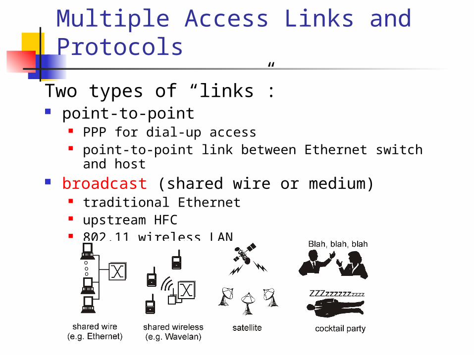
Multiple Access Links and Protocols
Two types of “links”: point-to-point
PPP for dial-up access point-to-point link between Ethernet switch and host
broadcast (shared wire or medium) traditional Ethernet upstream HFC 802.11 wireless LAN

Multiple Access Protocols Single shared broadcast channel
thus, if two or more simultaneous transmissions by nodes, due to interference, only one node can send successfully at a time (see CDMA later for an exception)
multiple access protocol Protocol that determines how nodes share
channel, i.e., determines when nodes can transmit Communication about channel sharing must use
channel itself ! Discussion: properties of an ideal multiple access
protocol.

Ideal Multiple Access Protocol
Broadcast channel of rate R bps Efficiency: when one node wants to
transmit, it can send at rate R Fairness: when N nodes want to
transmit, each can send at average rate R/N
Decentralized: no special node to coordinate
transmissions no synchronization of clocks
Simple

MAC Protocols: a taxonomyThree broad classes: Channel Partitioning
divide channel into smaller “pieces” (time slots, frequency, code)
allocate piece to node for exclusive use Random Access
channel not divided, allow collisions “recover” from collisions
“Taking turns” Nodes take turns, but nodes with more to
send can take longer turns

Multiple Access protocols single shared broadcast channel two or more simultaneous transmissions by
nodes: interference collision if node receives two or more signals at
the same timemultiple access protocol distributed algorithm that determines how
nodes share channel, i.e., determine when node can transmit
communication about channel sharing must use channel itself! no out-of-band channel for coordination

Random Access Protocols When node has packet to send
transmit at full channel data rate R. no a priori coordination among nodes
two or more transmitting nodes == “collision”,
random access MAC protocol specifies: how to detect collisions how to recover from collisions (e.g., via delayed
retransmissions) Examples of random access MAC protocols:
slotted ALOHA ALOHA CSMA, CSMA/CD, CSMA/CA

Evolution of Contention Protocols
Aloha
SlottedAloha
Improvement: Start transmission only at fixed times (slots)
CSMA
CSMA = Carrier Sense Multiple AccessImprovement: Start transmission only if no transmission is ongoing
CD = Collision DetectionImprovement: Stop ongoing transmission if a collision is detected (e.g. Ethernet)
CSMA/CD
Developed in the 1970s for a packet radio network

Slotted ALOHAAssumptions all frames same size time is divided into
equal size slots, time to transmit 1 frame
nodes start to transmit frames only at beginning of slots
nodes are synchronized
if 2 or more nodes transmit in slot, all nodes detect collision
Operation when node obtains fresh
frame, it transmits in next slot
no collision, node can send new frame in next slot
if collision, node retransmits frame in each subsequent slot with prob. p until success

Pure (unslotted) ALOHA unslotted ALOHA: simpler, no
synchronization when frame first arrives
transmit immediately collision probability increases:
frame sent at t0 collides with other frames sent in [t0-1,t0+1]

CSMA (Carrier Sense Multiple Access)
CSMA: listen before transmit:If channel sensed idle: transmit entire frame If channel sensed busy, defer transmission
Human analogy: don’t interrupt others!

CSMA collisionscollisions can still occur:propagation delay means two nodes may not heareach other’s transmissioncollision:entire packet transmission time wasted
spatial layout of nodes
note:role of distance & propagation delay in determining collision probability

CSMA/CD (Collision Detection)
CSMA/CD: carrier sensing, deferral as in CSMA collisions detected within short time colliding transmissions aborted, reducing channel
wastage collision detection:
easy in wired LANs: measure signal strengths, compare transmitted, received signals
difficult in wireless LANs: receiver shut off while transmitting
human analogy: the polite conversationalist

CSMA/CD collision detection

“Taking Turns” MAC protocols
channel partitioning MAC protocols: share channel efficiently and fairly at high load inefficient at low load: delay in channel access,
1/N bandwidth allocated even if only 1 active node!
Random access MAC protocols efficient at low load: single node can fully
utilize channel high load: collision overhead
“taking turns” protocolslook for best of both worlds!

“Taking Turns” MAC protocols
Polling: master node
“invites” slave nodes to transmit in turn
concerns: polling overhead latency single point of
failure (master)
Token passing: control token passed
from one node to next sequentially.
token message concerns:
token overhead latency single point of failure
(token)

Summary of MAC protocols
What do you do with a shared media? Channel Partitioning, by time, frequency or
code Time Division, Frequency Division
Random partitioning (dynamic), ALOHA, S-ALOHA, CSMA, CSMA/CD carrier sensing: easy in some technologies (wire),
hard in others (wireless) CSMA/CD used in Ethernet CSMA/CA used in 802.11
Taking Turns polling from a central site, token passing

Chapter Summary
principles behind data link layer services: error detection, correction sharing a broadcast channel: multiple access MAC protocols

Backup slides
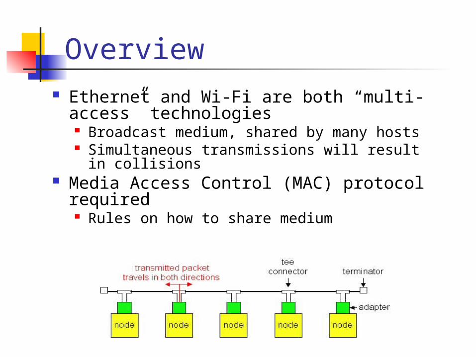
Overview Ethernet and Wi-Fi are both “multi-
access” technologies Broadcast medium, shared by many hosts Simultaneous transmissions will result in
collisions Media Access Control (MAC) protocol
required Rules on how to share medium

Media Access Control Protocols
Channel partitioning Divide channel into smaller “pieces” (e.g., time
slots, frequency) Allocate a piece to node for exclusive use E.g. Time-Division-Multi-Access (TDMA) cellular
network
Taking-turns Tightly coordinate shared access to avoid
collisions E.g. Token ring network
Contention Allow collisions “recover” from collisions E.g. Ethernet, Wi-Fi

Contention Media Access Control Goals
Share medium If two users send at the same time, collision results
in no packet being received (interference) If no users send, channel goes idle Thus, want to have only one user send at a time
Want high network utilization TDMA doesn’t give high utilization
Want simple distributed algorithm no fancy token-passing schemes that avoid
collisions

Evolution of Contention Protocols
Aloha
SlottedAloha
Improvement: Start transmission only at fixed times (slots)
CSMA
CSMA = Carrier Sense Multiple AccessImprovement: Start transmission only if no transmission is ongoing
CD = Collision DetectionImprovement: Stop ongoing transmission if a collision is detected (e.g. Ethernet)
CSMA/CD
Developed in the 1970s for a packet radio network

(Pure) ALOHA
Topology: Broadcast medium with multiple stations
Aloha Protocol: Whenever a station has data, it
transmits immediately
Receivers ACK all packets
No ACK = collision. Wait a random time and retransmit

Simple, but Radical Previous attempts all partitioned
channel TDMA, FDMA, etc.
Aloha optimized the common case (few senders) and dealt with collisions through retries

Trade-off Compared to TDMA
In TDMA, you always have to wait your turn
delay proportional to number of sites
In Aloha, can send immediately
Aloha gives much lower delays, at the price of lower utilization (as we will see)

Collisions in (Pure) ALOHA
1.1 1.2
TransmissionTime
(F)
Station 1
2.1Station 2
3.1 3.2Station 3
Broadcastchannel
2.2
1.3
CompleteCollision
PartialCollision
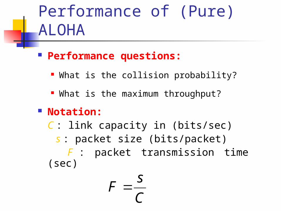
Performance of (Pure) ALOHA Performance questions:
What is the collision probability?
What is the maximum throughput?
Notation:C : link capacity in (bits/sec)
s : packet size (bits/packet) F : packet transmission time (sec)
C
sF

Frame which collideswith start of red frame
Frame
t0-F t0 t0+F
VulnerablePeriod of red frame
Time
Frame which collideswith end of red frame
Collisions and Vulnerable Period
A frame (red frame) will be in a collision if and only if another transmission begins in the vulnerable period of the frame
Vulnerable period has the length of 2 frame times

Traffic Model
FsC
rateservicetotal
ratearrivaltotalloadoffered
+
1
2
3
i
1
3
2
i
Poisson rate from all stations (Poisson Process’s are additive)
tetf )(
Inter-arrival time is exponentially distributed

System Model
p
1 -p
p r
(1 -p )rr
pGG
c o llis io n
s e rvic e d
p
1 -pG *+
Fact: Bernoulli sampling of a PP is also a PP
p Probability of collision
G Total carried load (incl. Retransmissions)

Probability of Collision
FGeFineventsomePp 21)2__(
Frame which collideswith start of red frame
Frame
t0-F t0 t0+F
VulnerablePeriod of red frame
Time
Frame which collideswith end of red frame
If Poisson events occur at rate ,
P (no event in T seconds) = e-T
2F

Throughput and Total Carried Load
pGG GFGe 2
RF 2Re
From
)( stable DelayE
FGsC
GR
/ load carried totalnormalized
If stable, all offered traffic is serviced, and r is also the throughput.
Expression characterizes throughput vs. total carried load including retransmissions. What is ALOHA’s maximum throughput?

Maximum Throughput
18.02
1 1max e
Maximum achievable throughput:
0dR
d0)2( 22 RR eeR
2
1R
Observe: if offered load > 0.18*C, unstable

Performance of ALOHA
• Maximum throughput approximately 18% of the capacity• Can do better with improved control • However, ALOHA is still used for its simplicity
•Ex. Cell phone call establishment
0 0.5 1 1.5 2 2.50
0.18
0.36
0.54
R
Thr
ough
put
(Pur
e A
LOH
A)
Ideal (no collisions):R
Pure ALOHA: Re-2R

Slotted ALOHA (S-ALOHA)
The Slotted Aloha Protocol Slotted Aloha - Aloha with an additional constraint Time is divided into discrete time intervals (=slot) A station can transmit only at the beginning of a
frame
As a consequence: Frames either collide completely or do not collide
at all Vulnerable period = ?

Collisions in S-ALOHA1.1 1.2
TransmissionDelay
Station 1
2.1Station 2
3.1 3.2
Station 3
Broadcastchannel
2.2
1.3
CompleteCollision
GFi eFYPp 1)(

Total Throughput in S-ALOHA:
Maximum achievable throughput:
Performance gain but requires nodes to have synchronized frame boundaries
Performance of S-ALOHA
37.01max e
RRe

Comparison of ALOHA and S-ALOHA
0 0.5 1 1.5 2 2.5 30
0.1
0.2
0.3
0.4
0.5
R
Thr
ough
put
(ALO
HA
)
Slotted ALOHA: Re-R
Pure ALOHA: Re-2R
Ideal (no collisions): R

802.3 Ethernet
Broadcast technology
Carrier-sense multiple access with collision detection (CSMA/CD). MA = multiple access CS = carrier sense CD = collision detection
Base Ethernet standard is 10 Mbps. Original design was ~2 Mbps 100Mbps, 1Gbps, 10Gbps
host host host host
host host host host
Hub
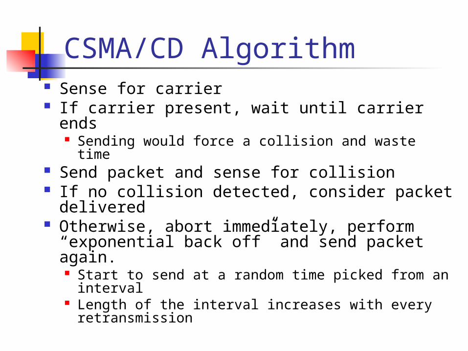
CSMA/CD Algorithm Sense for carrier If carrier present, wait until carrier ends
Sending would force a collision and waste time Send packet and sense for collision If no collision detected, consider packet
delivered Otherwise, abort immediately, perform
“exponential back off” and send packet again. Start to send at a random time picked from an
interval Length of the interval increases with every
retransmission

CSMA/CD: Some Details
When a sender detects a collision, it sends a “jam signal” Make sure that all nodes are aware
of the collision Length of the jam signal 48 bits
Exponential backoff operates in multiples of 512 bit time

CSMA collisions
Collisions can occur:propagation delay means two nodes may not hear each other’s transmissionCollision:entire packet transmission time wasted
spatial layout of nodes along ethernet
Note:role of distance and propagation delay in determining collision prob.

CSMA/CD (Collision Detection)
Collisions detected within short time
Colliding transmissions aborted, reducing channel wastage
Easy in wired LANs: measure signal strengths, compare transmitted, received signals
Difficult in wireless LANs

CSMA/CD collision detection

Minimum Packet Size
Why put a minimum packet size? Give a host enough time to detect collisions In Ethernet, minimum packet size = 64
bytes (two 6-byte addresses, 2-byte type, 4-byte CRC, and 46 bytes of data)
If host has less than 46 bytes to send, the adaptor pads (adds) bytes to make it 46 bytes
What is the relationship between minimum packet size and the length of the LAN?

Minimum Packet Size (more)
propagation delay (d)a) Time = t; Host 1 starts to send frame
Host 1 Host 2
propagation delay (d)
Host 1 Host 2b) Time = t + d; Host 2 starts to send a frame just before it hears fromhost 1’s frame
propagation delay (d)
Host 1 Host 2c) Time = t + 2*d; Host 1 hears Host 2’s frame detects collision
LAN length = (min_frame_size)*(light_speed)/(2*bandwidth) = = (8*64b)*(2.5*108mps)/(2*107 bps) = 6400m approx

Exponential Backoff Algorithm
Ethernet uses the exponential backoff algorithms to determine when a station can retransmit after a collision
Algorithm:• Set “slot time” equal to 512bit time• After first collision wait 0 or 1 slot times• After i-th collision, wait a random number between 0 and 2i-1 time slots• Do not increase random number range, if i=10• Give up after 16 collisions

Frame Frame Frame Frame
t0 Contention Slotst1
Contention interval Idle
CSMA/CD Contention Interval
Contention slots end in a collision Contention interval is a sequence of contention slots Length of a slot in contention interval is 512 bit time
time

Ethernet Frame Structure Sending adapter encapsulates IP
datagram
Preamble: 7 bytes with pattern 10101010 followed by
one byte with pattern 10101011 Used to synchronize receiver, sender clock
rates

Ethernet Frame Structure (more)
Addresses: 6 bytes, frame is received by all adapters on a LAN and dropped if address does not match
Type: 2 bytes, is actually a length field in 802.3
CRC: 4 bytes, checked at receiver, if error is detected, the frame is simply dropped
Data payload: maximum 1500 bytes, minimum 46 bytes

Ethernet Technologies: 10Base2
10: 10Mbps; 2: under 200 meters max cable length Thin coaxial cable in a bus topology
Repeaters used to connect up to multiple segments Repeater repeats bits it hears on one interface to its other
interfaces: physical layer device only!

10BaseT and 100BaseT 10/100 Mbps rate; latter called “fast
Ethernet” T stands for Twisted Pair Hub to which nodes are connected by
twisted pair, thus “star topology”

10BaseT and 100BaseT (more) Max distance from node to Hub is 100 meters Hub can gather monitoring information,
statistics for display to LAN administrators
Hubs still preserve one collision domain Every packet is forwarded to all hosts
Use bridges to address this problem Bridges forward a packet only to the destination
leading to the destination Next lecture

Gbit Ethernet
Use standard Ethernet frame format Allows for point-to-point links and
shared broadcast channels In shared mode, CSMA/CD is used;
short distances between nodes to be efficient
Full-Duplex at 1 Gbps for point-to-point links

Building Large LAN Using Bridges
Bridges connect multiple IEEE 802 LANs at layer 2 Datagram packet switching Only forward packets to the right port Reduce collision domain
In contrast, hubs rebroadcast packets
host host host host host
host host host host host
host
host
Bridge

Transparent Bridges Overall design goal: Complete
transparency “Plug-and-play” Self-configuring without hardware or software
changes Bridges should not impact operation of existing LANs
Three parts to transparent bridges:(1) Forwarding of Frames(2) Learning of Addresses(3) Spanning Tree Algorithm
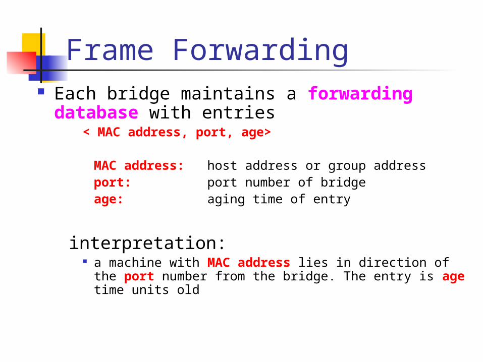
Frame Forwarding Each bridge maintains a forwarding
database with entries< MAC address, port, age>
MAC address: host address or group address
port: port number of bridge
age: aging time of entry
interpretation: a machine with MAC address lies in direction of the
port number from the bridge. The entry is age time units old

Assume a frame arrives on port x
Frame Forwarding 2
Bridge 2Port A Port C
Port x
Port B
Search if MAC address of destination is listed for ports A, B, or C
Forward the frame on theappropriate port
Flood the frame, i.e., send the frame on all
ports except port x
Found?
Notfound ?

In principle, the forwarding database could be set statically (=static routing)
In the 802.1 bridge, the process is made automatic with a simple heuristic:
The source field of a frame that arrives on a port tells which hosts are reachable from this port.
Address Learning
Bridge 2Port A Port C
Port x
Port BLAN 3
host n

Algorithm: For each frame received, stores the source
address in the forwarding database together with the port where the frame was received.
An entry is deleted after some time out (default is 15 seconds).
Address Learning 2
Bridge 2Port A Port C
Port x
Port BLAN 3
host n

Example
Bridge 2
Port1
LAN 1
A
LAN 2
CB D
LAN 3
E F
Port2
Bridge 2
Port1 Port2
•Consider the following packets: <Src=A, Dest=F>, <Src=C, Dest=A>, <Src=E, Dest=C>
•What have the bridges learned?XX YY

Consider the two LANs that are connected by two bridges.
Assume host n is transmitting a frame F with unknown destination.
What is happening? Bridges A and B flood the frame
to LAN 2. Bridge B sees F on LAN 2 (with
unknown destination), and copies the frame back to LAN 1
Bridge A does the same. The copying continuesWhere’s the problem? What’s
the solution ?
Danger of Loops
LAN 2
LAN 1
Bridge BBridge A
host n F

The solution to the loop problem is to not have loops in the topology
IEEE 802.1 has an algorithm that builds and maintains a spanning tree in a dynamic environment.
Bridges exchange messages (Configuration Bridge Protocol Data Unit (BPDU)) to configure the bridge to build the tree.
Spanning Trees

What’s a Spanning Tree?
A subset of edges of a graph that spans all the nodes without creating any cycle (i.e. a tree)
4
5
7
1 2
6
3

802.1 Spanning Tree Approach (Sketch)
Elect a bridge to be the root of the tree Every bridge finds shortest path to the
root Union of these paths become the
spanning tree
4
5
7
Root 2
6
3

What do the BPDU messages do?
With the help of the BPDUs, bridges can: Elect a single bridge as the root bridge. Calculate the distance of the shortest path to
the root bridge Each LAN can determine a designated bridge,
which is the bridge closest to the root. The designated bridge will forward packets towards the root bridge.
Each bridge can determine a root port, the port that gives the best path to the root.
Select ports to be included in the spanning tree.
Concepts Each bridge as a unique identifier:
Bridge ID = <MAC address + priority level>Note that a bridge has several MAC addresses
(one for each port), but only one ID
Each port within a bridge has a unique identifier (port ID).
Root Bridge: The bridge with the lowest identifier is the root of the spanning tree.
Path Cost: Cost of the least cost path to the root from the port of a transmitting bridge; Assume it is measured in # of hops to the root.
Root Port: Each bridge has a root port which identifies the next hop from a bridge to the root.

Concepts Root Path Cost: For each bridge, the cost of the
min-cost path to the root Designated Bridge, Designated Port: Single
bridge on a LAN that provides the minimal cost path to the root for this LAN:
- if two bridges have the same cost, select the one with highest priority (smallest bridge ID)
- if the min-cost bridge has two or more ports on the LAN, select the port with the lowest identifier
Note: We assume that “cost” of a path is the number of “hops”.

A Bridged Network
B3B3
B5B5
B2B2B7B7
B1B1
B4B4B6B6

Steps of Spanning Tree Algorithm
1. Determine the root bridge2. Determine the root port on all other
bridges3. Determine the designated bridge on
each LAN
Each bridge is sending out BPDUs that contain the following information:root bridge (what the sender thinks it is)
root path cost for sending bridgeIdentifies sending bridge
root IDroot ID costcost bridge ID/port IDbridge ID/port ID

Ordering of Messages We can order BPDU messages with the following
ordering relation ““ (let’s call it “lower cost”):
If (R1 < R2)M1 M2
elseif ((R1 == R2) and (C1 < C2)) M1 M2
elseif ((R1 == R2) and (C1 == C2) and (B1 < B2))M1 M2
elseM2 M1
ID R1ID R1 C1C1 ID B1 ID B1 ID R2ID R2 C2 C2 ID B2ID B2M1 M2

Initially, all bridges assume they are the root bridge.
Each bridge B sends BPDUs of this form on its LANs:
Each bridge looks at the BPDUs received on all its ports and its own transmitted BPDUs.
Root bridge is the smallest received root ID that has been received so far (Whenever a smaller ID arrives, the root is updated)
Determine the Root Bridge
BB 00 BB

At this time: A bridge B has a belief of who the root is, say R.
Bridge B determines the Root Path Cost (Cost) as follows:
If B = R : Cost = 0. If B ≠ R: Cost = {Smallest Cost in any of BPDUs that
were received from R} + 1
B’s root port is the port from which B received the lowest cost path to R (in terms of relation ““).
Knowing R and Cost, B can generate its BPDU (but will not necessarily send it out):
Calculate the Root Path CostDetermine the Root Port
RR CostCost BB

At this time: B has generated its BPDU
B will send this BPDU on one of its ports, say port x, only if its BPDU is lower (via relation ““) than any BPDU that B received from port x.
In this case, B also assumes that it is the designated bridge for the LAN to which the port connects.
Calculate the Root Path CostDetermine the Root Port
RR CostCost BB
Bridge BPort A Port C
Port x
Port B

Selecting the Ports for the Spanning Tree At this time: Bridge B has calculated the root,
the root path cost, and the designated bridge for each LAN.
Now B can decide which ports are in the spanning tree:
B’s root port is part of the spanning tree All ports for which B is the designated bridge are part
of the spanning tree. B’s ports that are in the spanning tree will
forward packets (=forwarding state) B’s ports that are not in the spanning tree will
not forward packets (=blocking state)

A Bridged Network (End of Spanning Tree Computation)
B3B3
B5B5
B2B2B7B7
B1B1
B4B4B6B6
x
x
x

Ethernet Switches Bridges make it possible to increase LAN
capacity. Packets are no longer broadcasted - they are only
forwarded on selected links Adds a switching flavor to the broadcast LAN
Ethernet switch is a special case of a bridge: each bridge port is connected to a single host.
Can make the link full duplex (really simple protocol!)
Simplifies the protocol and hardware used (only two stations on the link) – no longer full CSMA/CD
Can have different port speeds on the same switch Unlike in a hub, packets can be stored

Can the Internet be One Big Switched Ethernet?
Inefficient Too much flooding
Explosion of forwarding table
Need to have one entry for every Ethernet address in the world!
Poor performance Tree topology does
not have good load balancing properties
Hot spots Etc…
LAN 2
Bridge 2
LAN 5
LAN 3
LAN 1
LAN 4
Bridge 5
Bridge 4Bridge 3
d
Bridge 1