COMMUNICATION, NAVIGATION AND SURVEILLANCE MANUAL … MAN VOL 3.pdf · COMMUNICATION, NAVIGATION...
49
COMMUNICATION, NAVIGATION AND SURVEILLANCE MANUAL VOLUME - III SITING CRETERIA OF CNS FACILITIES DEPARTMENT OF CIVIL AVIATION MYANMAR 1 st Edition, 2009
Transcript of COMMUNICATION, NAVIGATION AND SURVEILLANCE MANUAL … MAN VOL 3.pdf · COMMUNICATION, NAVIGATION...

COMMUNICATION, NAVIGATION AND
SURVEILLANCE MANUAL
VOLUME - III
SITING CRETERIA OF CNS FACILITIES
DEPARTMENT OF CIVIL AVIATION
MYANMAR
1st Edition, 2009

[BLANK]

Department of Civil Aviation, Myanmar CNS Manual Volume III
2009 1st Edition i
PREFACE
This is the Third Volume in the series of seven volumes of CNS manuals prepared and maintained by Director (CNS), CNS Head Quarter on behalf of Department of Civil Aviation, Myanmar for the use and guidance of its executives and staff. The topics covered under these volumes are as under:-
Volume I – Maintenance of CNS Facilities Volume II – Communication Procedures Volume III – Siting Criteria of CNS Facilities Volume IV – Flight Inspection of CNS Facilities Volume V – Lightning & Surge Protection and Earthing System of CNS Installations Volume VI – Technical Specifications Volume VII – Maintenance Schedules of CNS Facilities
This Volume contains various criteria for selection of sites for locating CNS facilities including that for GNSS. The criteria and guidelines for selection of sites are largely based on standards and recommended practices given in ICAO Annex 10, Volume I. The information contained in this Volume shall be extremely useful by the field staff in carrying out preliminary selection of sites out of which one may be finally approved by the siting board.
Use, comments and suggestions for improvement of this volume may be sent to DD (CNS) so
as to incorporate them in the next version of this volume.
******

Department of Civil Aviation, Myanmar CNS Manual Volume III
2009 1st Edition ii
[BLANK]

Department of Civil Aviation, Myanmar CNS Manual Volume III
2009 1st Edition iii
Record of Amendments
No. Amendment Date Incorporated on Incorporated by

Department of Civil Aviation, Myanmar CNS Manual Volume III
2009 1st Edition iv
[BLANK]

Department of Civil Aviation, Myanmar CNS Manual Volume III
2009 1st Edition v
TABLE OF CONTENTS
PREFACE ……………………………………………………………………………………………………………………………. i
Record of Amendments .................................................................................................................. iii
TABLE OF CONTENTS ……………………………………………………………………………………………………… v
CHAPTER - 1 General 1
CHAPTER - 2 Siting Criteria of CNS Facilities 3
1.1 Purpose ……………………………………………………………………………………………………………………….. 3
1.2 References …………………………………………………………………………………………………………………. 3
1.3 Standard and practices …………………………………………………………………………………………………...3
CHAPTER - 3 Siting Criteria for Instrument Landing System (ILS) 5
1.0 General ……………………………………………………………………………………………………………………….. 5
1.1 Introduction ………………………………………………………………………………………………………………… 5
1.2 Critical/Sensitive Areas …………………………………………………………………………………………………. 5
1.3 Services ………………………………………………………………………………………………………………….. 5
1.4 Construction ………………………………………………………………………………………………………………… 5
1.5 Aircraft …………………………………………………………………………………………………………………. 6
1.6 Vehicle and Plant ………………………………………………………………………………………………………….. 6
1.7 Road Use ………………………………………………………………………………………………………………….. 6
1.8 Access Control ………………………………………………………………………………………………………………. 6
1.9 Signs ………………………………………………………………………………………………………………….. 6
2.0 Siting Criteria for Localizer ……………………………………………………………………………………………. 6
2.1 Localizer Location ………………………………………………………………………………………………………… 6
2.2 Critical Area …………………………………………………………………………………………………………………. 8
2.3 NOC Criteria ………………………………………………………………………………………………………………… 8
2.4 Sensitive Area ………………………………………………………………………………………………………………. 8
2.5 Grading Requirements ………………………………………………………………………………………………….. 8
2.6 Requirements of off set Localizer …………………………………………………………………………………… 9
2.7 Equipment Shelter ……………………………………………………………………………………………………….. 9
3.0 Siting Criteria for Glide Path ………………………………………………………………………………………… 10
3.1 General ………………………………………………………………………………………………………………… 10
3.2 Criteria for Roughness …………………………………………………………………………………………………. 10
3.2.1 Extent of Roughness ……………………………………………………………………………………….. 11
3.3 Critical Area ………………………………………………………………………………………………………………… 11
3.4 Sensitive Area ……………………………………………………………………………………………………………… 11
3.5 Site Preparation …………………………………………………………………………………………………………… 11
3.6 Locating the Glide Slope Facility …………………………………………………………………………………… 12
3.6.1 General …………………………………………………………………………………………………………..12
3.6.2 Lateral Distance Criteria …………………………………………………………………………………. 12
3.6.3 Longitudinal Distance Requirements ……………………………………………………………….. 12
3.7 Requirement of obstruction-free Area for Glide Path ……………………………………………………… 14

Department of Civil Aviation, Myanmar CNS Manual Volume III
2009 1st Edition vi
4.0 Siting Criteria for Marker Beacon …………………………………………………………………………………..15
4.1 General ………………………………………………………………………………………………………………… 15
4.2 Site Location ……………………………………………………………………………………………………………….. 15
4.2.1 Middle Marker ………………………………………………………………………………………….. 15
4.2.2 Outer Marker ……………………………………………………………………………………………. 15
4.2.3 Obstructions …………………………………………………………………………………………….. 15
4.2.4 Vehicular Movements ……………………………………………………………………………….. 15
4.2.5 Services ……………………………………………………………………………………………………. 15
4.2.6 Electrical Interference ........................................................................................... 15
4.2.7 Restricted Area ………………………………………………………………………………………… 15
4.2.8 Maintenance of Site ………………………………………………………………………………….. 16
5.0 Siting Criteria of Locator Beacons …………………………………………………………………………………. 16
6.0 General Instructions on selection of sites for ILS ...................................................................... 16
CHAPTER - 4 Siting Criteria of Very High Frequency Omni Range (VOR) 19
1.0 General ……………………………………………………………………………………………………………….. 19
2.0 Siting Criteria for CVOR ………………………………………………………………………………………………. 19
2.1 Natural Terrain …………………………………………………………………………………………………………… 19
2.1.1 Adjacent Terrain ………………………………………………………………………………………. 19
2.1.2 Distant terrain ………………………………………………………………………………………….. 21
2.2 Obstruction Criteria …………………………………………………………………………………………………….. 21
2.2.1 Trees and Forests ……………………………………………………………………………………… 21
2.2.2 Wire Fences ……………………………………………………………………………………………… 21
2.2.3 Power and Control Lines …………………………………………………………………………… 22
2.3 Structures ................................................................................................................................ 22
3.0 Siting Criteria for DVOR ……………………………………………………………………………………………… 22
4.0 General Instructions …………………………………………………………………………………………………… 23
Chapter - 5 Siting Criteria for Distance Measuring Equipment (DME) 27
1.0 Introduction ………………………………………………………………………………………………………………. 27
2.0 Siting Requirements …………………………………………………………………………………………………… 27
2.1 Site .............................................................................................................................. 27
2.2 Obstructions ……………………………………………………………………………………………………………….. 27
2.3 Antenna Height …………………………………………………………………………………………………………… 27
2.4 Collocation of DME with VOR ………………………………………………………………………………………. 27
2.5 Vehicular Movements …………………………………………………………………………………………………. 28
2.6 Services ……………………………………………………………………………………………………………….. 28
2.7 Electrical Interference …………………………………………………………………………………………………. 28
2.8 Restricted Area ………………………………………………………………………………………………………….. 28
2.9 Maintenance of the Site ……………………………………………………………………………………………….. 28

Department of Civil Aviation, Myanmar CNS Manual Volume III
2009 1st Edition vii
CHAPTER – 6 Siting Criteria of Non Directional Radio Beacons (NDB) 29 1.0 General ………………………………………………………………………………………………………………. 29
1.1 Land Requirement ………………………………………………………………………………………….. 29 2.0 Siting ……………………………………………………………………………………………………………….. 29 3.0 Obstructions ………………………………………………………………………………………………………………. 29 4.0 Vehicular Movements …………………………………………………………………………………………………. 29
5.0 Services …………………………………………………………………………………………………………………30
6.0 Electrical Interference ………………………………………………………………………………………………… 30
7.0 Site Maintenance ………………………………………………………………………………………………………. 30
8.0 General Instructions for selection of site for NDB ………………………………………………………….. 30
CHAPTER - 7 Siting Criteria for Microwave (UHF) Link and Extended Range VHF 31
1.0 Microwave Link ………………………………………………………………………………………………………….. 31
1.1 General ................................................................................................................................. 31
1.2 Siting ………………………………………………………………………………………………………………… 31
1.3 NOC Requirements ……………………………………………………………………………………………………… 31
2.0 Extended Range VHF ………………………………………………………………………………………………….. 31
2.1 General ……………………………………………………………………………………………………………….. 31
2.2 Siting ……………………………………………………………………………………………………………….. 31
CHAPTER 8 Siting Criteria for Global Navigation Satellite System (GNSS) 33
1.0 GNSS Applications ……………………………………………………………………………………………………… 33
1.1 Enroute and Non-Precision Approach using ABAS .................................................................. 33
1.2 Ground Based Augmentation System (GBAS) ………………………………………………………………… 33
2.0 Siting of Ground to Air Data Link Antenna ……………………………………………………………………. 33
3.0 Space Based Augmentation System (SBAS) …………………………………………………………………… 34
CHAPTER 9 Siting Criteria for Radars 35
1.0 General Requirements …………………………………………………………………………………………………. 35
1.1 Road accessibility, power, telephone line availability ……………………………………………………… 35
1.2 Data Transmission to the Display Site …………………………………………………………………………….35
1.3 Shadows due to Geographic Obstructions ……………………………………………………………………… 36
1.4 Ground Clutter …………………………………………………………………………………………………………… 36
1.5 Lobing ……………………………………………………………………………………………………………….. 37
1.6 Interference with other electronic equipments ......................................................................... 37
2.0 Special Requirements for ARSR ……………………………………………………………………………………. 37
3.0 Special Requirements for ASR ……………………………………………………………………………………… 38
4.0 Special Requirement for ASDE …………………………………………………………………………………….. 38
5.0 Special Requirements for SSR ……………………………………………………………………………………… 39

Department of Civil Aviation, Myanmar CNS Manual Volume III
2009 1st Edition viii
[Blank]

Department of Civil Aviation, Myanmar CNS Manual Volume III
2009 1st Edition 1
CHAPTER - 1
GENERAL 1. Title of the Document
This document is identified as Communication, Navigation & Surveillance Manual – Vol. III (CNSM- Vol III) “Siting criteria of CNS facilities.”
2 Purpose of this Document 2.1 Purpose of this document is to provide information and guidelines pertaining to
selection of sites for installation of CNS facilities, which are essential for the provision of safe and efficient air traffic services by Department of Civil Aviation, Myanmar. It is published for use and guidance of its CNS Maintenance personnel.
3 Responsibility for documentation, review, amendments and publication 3.1 Director (CNS) is responsible for development, review and amendments of CNS –
Manuals Vol. III. He will ensure that the information and guidelines were pertaining to selection of site for installation of CNS facilities, as detailed in this manual are in conformity with Standards and Recommended Practices (SARPs) given in the Annexes to Convention on International Civil Aviation and National regulations.
3.2 Deputy Director (CNS) is responsible for the approval of documentation &
Amendments and publication of CNS-Manual. 4. Effective Date: 4.1 Effective date of Manual is indicated at the end of this chapter. 4.2 New edition will be indicated by the same date at the end of this chapter. 5. Change History: 5.1 This is version 1 of CNS Manual Vol. III. Changes, if any, are indicated on ‘Record of
Amendments and corrigenda page’. 5.2 Amendments – documentation being inserted in the manual must contain headers
and footers that are consistent with those given in this document. 6. Control of the manual: 6.1 Deputy Director (CNS) will control this Manual electronically through DCA web site. 7 Distribution of the Manual: 7.1 Deputy Director (CNS) may produce hard copies and control the distribution of these
Copies, as deemed appropriate. 8 Master Copy: 8.1 An electronic and a hard master copy of each chapter contained in the Manual will be
held and maintained by the Deputy Director (CNS).

Department of Civil Aviation, Myanmar CNS Manual Volume III
2009 1st Edition 2
9. Checking Currency of Manual: 9.1 A current copy of the Manual will be published on Department of Civil Aviation,
Myanmar web site. 10 Enquiries 10.1 Enquiries/Clarifications should be addressed to:
Director (CNS ), Department of Civil Aviation,Myanmar, HQ Building,Yangon International Airport Mingaladon, Yangon - 11021 Telephone: 095- 01- 533020 FAX : 095- 01- 533016
11. Effective Date: 23rd Nov 2009.
****

Department of Civil Aviation, Myanmar CNS Manual Volume III
2009 1st Edition 3
CHAPTER - 2
Siting Criteria of CNS Facilities 1 General Requirements 1.1 Purpose 1.1.1 This Chapter sets out various factors relevant to the siting of radio navigation aids
and indicates the restrictions which apply to buildings and other developments in the vicinity of existing and proposed navigation aids.
1.1.2 The Standards and Practices are applicable to all DCA certified facilities, all agencies/
persons involved in the siting and maintenance of these facilities and all agencies / persons involved in construction and other works in the vicinity of these facilities.
1.2 References
A. Annex 10 to the Convention on International Civil Aviation, Aeronautical Tele communications, Vol. I Part I.
B. Annex 14 to the Convention on International Civil Aviation, Aerodromes, Vol. I
C. DOC 9157 , Aerodrome Design Manual Part 6
1.3 Standard and Practices
1.3.1 General 1.3.1.1 The area in which a new navigation aid is to be installed is determined by operational
requirements. The actual site will normally be selected taking into account satisfaction of the operational requirements, construction aspects and maintainability.
1.3.1.2 Generally, the site selected should be reasonably level, have adequate drainage, be
above local flood levels of rivers or sea, and should not have an excess of vegetation such as high grass or trees. In addition, it is desirable that the site be close to electric power and telephone service connections and be accessible from existing roads. In mountainous areas it will often be impossible to find a site meeting these general requirements and satisfying the particular requirements of the aid to be installed. In this case the site chosen should be one that is capable of development to meet the main operational requirements at reasonable cost.
1.3.1.3 The standard siting criteria set out to define the minimum requirements for proper
performance of each type of navigation aid. Infringement of the siting standards and the restricted areas does not necessarily mean that a particular aid will be unusable or unsafe, although the service it provides may be degraded. In certain cases operational tolerance may permit some relaxation of these criteria. Any possible infringement to existing or planned facilities shall be assessed by the concerned CNS personnel to determine acceptability.
1.3.1.4 Another factor to be addressed is property ownership or control. Increasing difficulty
is being experienced where sites selected may infringe on the conditions of a statutory authority responsible for the area concerned. Conditions, if any, which

Department of Civil Aviation, Myanmar CNS Manual Volume III
2009 1st Edition 4
apply to the use of the land proposed are to be clarified with the appropriate authorities at an early stage of planning.
1.3.1.5 Fences and security signs, whilst complying with the appropriate standards, must be
located so as not to interfere with any nearby navigation aids. 1.3.1.6 Vibration due to blasting, construction etc., at the navigation aid site shall not exceed
5 mm/s.
****

Department of Civil Aviation, Myanmar CNS Manual Volume III
2009 1st Edition 5
CHAPTER - 3
Siting Criteria for Instrument Landing System (ILS) 1 General 1.1 Introduction
There are several components to an instrument landing system; i.e. the localizer, glide path, middle and outer markers, remote monitor and locator beacons. The component facilities perform specific functions and are separately located on the approach path to and alongside the runway they serve. Different siting requirements and restrictions to access and movement apply to each site.
1.2 Critical/Sensitive Areas 1.2.1 The occurrence of interference to ILS signals is dependent on the total environment
around the ILS antennas, and antenna characteristics. The environment, for the purpose of developing protective zoning criteria, can be divided into two types of area, the Critical Areas and the Sensitive Areas.
1.2.2 The Critical Area is an area of defined dimensions about the localizer and glide
path where vehicles, including aircraft, and any constructions (e.g. buildings, , trees, fences, etc.) will cause unacceptable disturbances to the ILS performance.
1.2.3 The Sensitive Area is an area extending beyond the critical area where the parking
and/or movement of vehicles, including aircraft, and the presence of buildings, trees, fences, etc. may affect the ILS performance.
1.3 Services
Within the site and restricted areas defined for ILS Localizer and ILS Glide Path, all power and control cables shall be laid underground.
1.4 Construction
No construction or variation to access is permitted within the Critical or Sensitive Areas without the prior approval of the DD (CNS). Following “General Issues” should be considered, before deciding on the ILS Installation:
1. Jet Blast: The typical location of non Visual aids, such as an ILS eqpt
300 m beyond the rwy end or a lateral displacement of 120 m wrt the rwy centre line), is such that Jet Blast loads do not exceed the environmental loads. In case the location has to be closure to the rwy, then Jet blast effects must be evaluated and if required suitable barriers may be considered.
2. Deflection: Deflection tolerances for ILS installations should be in accordance with the monitoring and operational limits of the facility performance category as per Annexe 10 Vol I
3. Frangibility: Any equipment or installation required for air navigation purposes which must be located
Department of Civil Aviation, Myanmar CNS Manual Volume III
2009 1st Edition 6
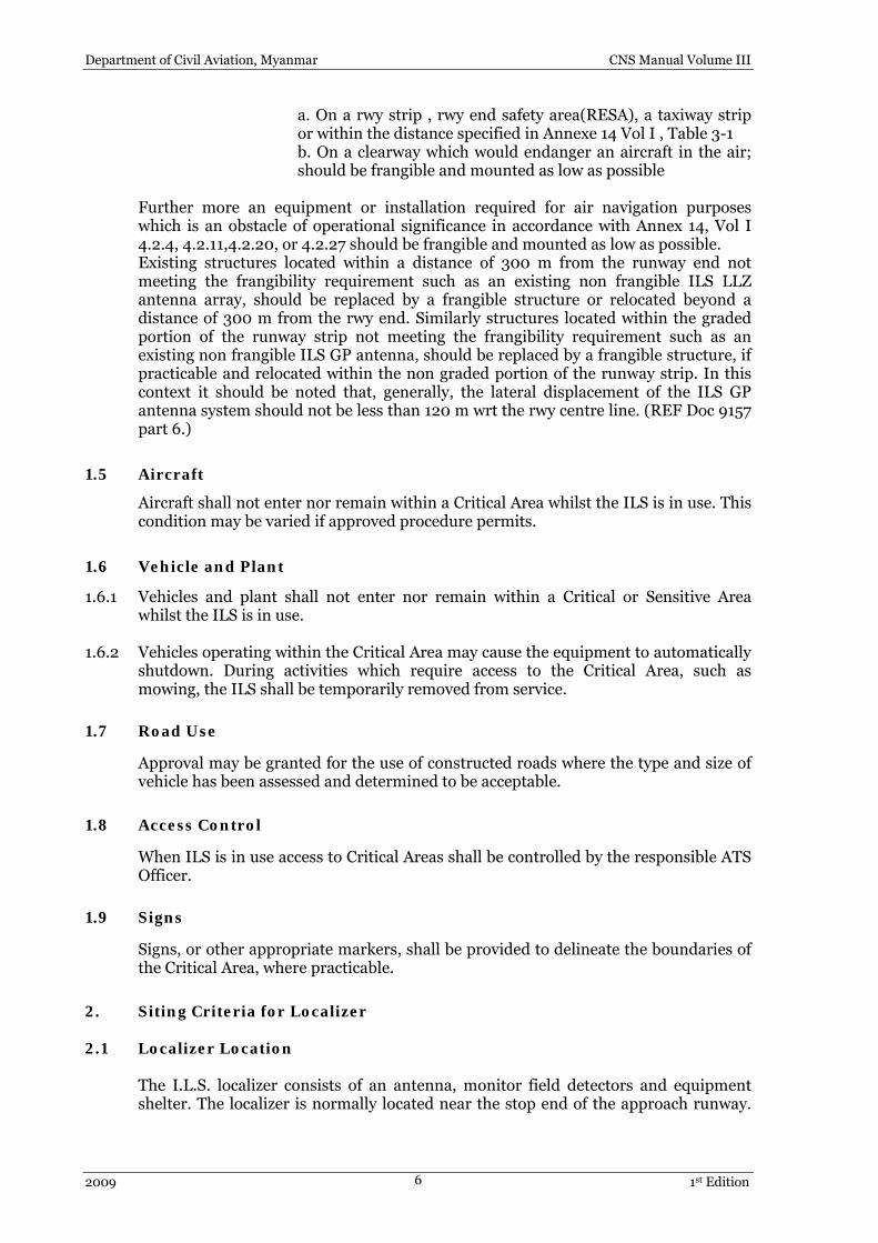
a. On a rwy strip , rwy end safety area(RESA), a taxiway strip or within the distance specified in Annexe 14 Vol I , Table 3-1 b. On a clearway which would endanger an aircraft in the air; should be frangible and mounted as low as possible
Further more an equipment or installation required for air navigation purposes which is an obstacle of operational significance in accordance with Annex 14, Vol I 4.2.4, 4.2.11,4.2.20, or 4.2.27 should be frangible and mounted as low as possible. Existing structures located within a distance of 300 m from the runway end not meeting the frangibility requirement such as an existing non frangible ILS LLZ antenna array, should be replaced by a frangible structure or relocated beyond a distance of 300 m from the rwy end. Similarly structures located within the graded portion of the runway strip not meeting the frangibility requirement such as an existing non frangible ILS GP antenna, should be replaced by a frangible structure, if practicable and relocated within the non graded portion of the runway strip. In this context it should be noted that, generally, the lateral displacement of the ILS GP antenna system should not be less than 120 m wrt the rwy centre line. (REF Doc 9157 part 6.)
1.5 Aircraft
Aircraft shall not enter nor remain within a Critical Area whilst the ILS is in use. This condition may be varied if approved procedure permits.
1.6 Vehicle and Plant
1.6.1 Vehicles and plant shall not enter nor remain within a Critical or Sensitive Area whilst the ILS is in use.
1.6.2 Vehicles operating within the Critical Area may cause the equipment to automatically
shutdown. During activities which require access to the Critical Area, such as mowing, the ILS shall be temporarily removed from service.
1.7 Road Use
Approval may be granted for the use of constructed roads where the type and size of vehicle has been assessed and determined to be acceptable.
1.8 Access Control
When ILS is in use access to Critical Areas shall be controlled by the responsible ATS Officer.
1.9 Signs
Signs, or other appropriate markers, shall be provided to delineate the boundaries of the Critical Area, where practicable.
2. Siting Criteria for Localizer 2.1 Localizer Location
The I.L.S. localizer consists of an antenna, monitor field detectors and equipment shelter. The localizer is normally located near the stop end of the approach runway.

Department of Civil Aviation, Myanmar CNS Manual Volume III
2009 1st Edition 7
The antenna array is the prime consideration and will, to a certain extent, fix the location of the building and that of the field detectors
2.1.1 The localizer antenna system must be symmetrically positioned about the extended
centerline of runway with the longitudinal axis of the array perpendicular to the extended runway centre line. The optimum distance from the stop end of the runway to the localizer array for each site is determined by consideration of several factors mainly:
1) The required obstruction clearance criteria. 2) Useable distance and signal coverage requirements. 3) Presence of reflecting or reradiating objects in the vicinity. 4) Safety considerations. 5) Back-course requirements. 6) Anticipated facility upgrading and/or airport expansion. 7) Establishment costs. 8) Approach Road
2.1.2 The criteria for minimum antenna distance from the stop end of runway is as follows:
a. Within 300m of the over run area (RESA) after the runway end, an
installed equipment should be of low mass and frangible.( Ref : 2.2 of C)
b. Equipment installed within the graded portion of the runway strip
should be of low mass and frangible. ( Ref : 2.2 of C) 1) The distance chosen shall preclude penetration of the approach surface plane by the localizer plane. 2) Where a clear or graded area extending to a distance of 1250 feet or more from the stop end of runway is provided, the localizer shall be located beyond 1000 ft. from the paved overrun. 3) Where the conditions preclude adherence to the approach surface plan, waivers of this criteria will be considered on individual bases. Approval of such waiver requests will be contingent on the relative antenna height, transmitter power, the distance under consideration etc.
Localizer will not be located at a distance less than 300 ft. from the stop end of the runway to ensure minimum protection from the effects of the aircraft engine jet blasts, at airports where commercial jet aircrafts are in operation. Where siting conditions preclude adherence to the 300 ft. limitation, consideration shall be given to the location of the array beyond the maximum distance limit or to an offset location.
2.1.3 The elevation of the array shall be considered in conjunction with the distance
requirements. Majority of airports require ground mounted array. In some selected airports elevated antenna array may become necessary to meet the required minimum signal coverage. This may occur due to hump in the runway or the presence of hills and other obstructions in the vicinity which causes a shadow effect. The array shall be mounted so that antenna radiating element is in line of sight with the

Department of Civil Aviation, Myanmar CNS Manual Volume III
2009 1st Edition 8
threshold crossing height at the approach end of the runway. The maximum height of the antenna shall not exceed 35 ft above immediate terrain.
2.2 Critical Area
The Critical Area for localizer extends 60 m on either side of the runway centre line commencing from 10m behind the localizer antenna and extending forward to a point 300m in front of the antenna. The critical area is shown in Fig. 2.1 of this chapter and Figs. C-3A, C-3B, C-4A and C-4B of Annex 10, Attachment C. However at places where there is no space behind the proposed antenna location, the requirement of space behind it can be dispensed with only where unidirectional Antenna array (Highly reduced back lobe radiation) is being used.
2.3 NOC Criteria
The area which is required to be kept free from any obstructions is defined by DCA NOC criteria. The area is bounded by the following:-
(a) A line 300 m in the direction of approaches from localizer antenna and
perpendicular to the runway. (b) A line 60 m from the centre line of localizer antenna on either side or
parallel to the runway. (c) A line containing centre of localizer antennas and perpendicular to the
runway. 2.4 Sensitive Area
The sensitive area commences at the localizer antenna origin and extends forward. Within this sector obstructions shall be less than 0.5º elevation, when measured from ground level at the antenna base. The sensitive area is shown in Fig. 2.1 of this chapter and Figs. C-3A, C-3B, C-4A and C-4B of Annex 10, Attachment C.
2.5 Grading Requirements
The presence of signal reflecting or re-radiating objects in the vicinity may place an additional restriction on the location of the localizer antenna system.
2.5.1 The terrain between the antennas and the end of the runway shall contain no severe
Irregularities or obstructions that may affect the localizer signal quality. Existing obstructions shall be removed and the critical area shall be graded.
a) Site grading requirements for critical area are as under:
1. Roughness shall be less than 15 cm
2. Slope in any direction less than 1 : 100
3. Transverse slope to be symmetrical about the extended centre line
b) Site grading requirements for Sensitive area are as under
1. Roughness shall be less than 30 cm
2. Slope in any direction less than 1 : 50

Department of Civil Aviation, Myanmar CNS Manual Volume III
2009 1st Edition 9
3. The area is to be clear of Localizer interference sources like metallic objects, trees, fencings, walls etc
NOTE: ALL Areas to fulfill ICAO Annex 14 and for Grading etc 2.6 Requirements of off set Localizer
At some runways, terrain may prevent the localizer antennae from being positioned on the extended centerline of runway. The localizer antenna array may be off set so that course does not lie along the runway centerline but rather intercepts the centerline at a point determined by the amount of angular offset. The maximum localizer offset angle shall be 3º. The localizer offset angle is formed by vertical plane containing the runway centre line, and the vertical plane containing both the decision height point and the point on the runway centerline that is 1150 ± 50 feet inbound from the decision height point with the later plane also containing the localizer course line. The criteria for standard localizer facilities shall apply also to an offset localizer with the following exceptions or amendments:
1) The antenna array shall be off set in the direction that will offer the least signal interference from the movement or obstructions. The distance from the array to the approach threshold shall not exceed the perpendicular extension of 2000 feet distance limit from the stop end of the runway that applies to the normal localizer configurations.
2) The offset localizer shall comply with the minimum distance of the array from the stop end of the runway and from the runway centerline and ILS runway obstruction criteria.
3) No element of the array shall penetrate a 10:1 surface originating at a point on the runway centerline nearest the array.
4) No antenna array shall be sited to provide vertical and horizontal clearance to taxing aircraft on adjacent taxiways.
2.7 Equipment Shelter
The criteria for location of equipment shelter are:-
(a) The shelter shall not be located between any portion of the permissible
antenna location and the runway. (b) The shelter shall not be located within 250 ft. of the extended runway
centerline if the location falls within 300 m of RESA.. (c) If an elevated array is installed, the shelter may be located directly
behind or below the platform, provided the elevation of the top of shelter does not exceed the level of the platform.
(d) The shelter should have an approach road. The location and dimension of the hut should also meet Annex 14 grading and obstruction requirements as per DOC 9157 part 6 requirements for frangibility and construction.

Department of Civil Aviation, Myanmar CNS Manual Volume III
2009 1st Edition 10
Sensitive area (X,Y) Category I X 600 m (2000 ft)
Y 60 m ( 200 ft) Category II X 1220 m (4000 ft)
Y 90 m ( 300 ft) Category III X 2750 m (9000 ft)
Y 90 m ( 300 ft)
FIG. 2.1 Typical localiser critical and sensitive areas
3 Siting Criteria for Glide Path 3.1 General
The glide slope antenna system is located in a line parallel to the runway centerline and offset from the runway centerline. The glide slope site may be located on either side of the runway. The most reliable operation will occur when it is located on the side that provides the least interference from the buildings, power lines, moving vehicles and aircraft and area which has greatest extent of smooth terrain outbound from the glide path antennas. The glide slope depends on the terrain conditions due to inherent image antenna concept. Radiation from an antenna located above a reflecting surface (the ground terrain in the case of glide slope) travels to different paths to the receiving antenna, a direct path and an indirect path via the reflecting surface. The reflected signal appears to emanate from an image” antenna along the same vertical plane as the real antenna and at a distance below the reflecting surface equal to the distance of the real antenna above the surface. Siting of glide slope is limited by the terrain irregularity or roughness in front of the antenna. The degrading effect of rough terrain results from the random dispersion and /or phase shift of the ground plane signal, which precludes formation of the desired glide slope pattern.
3.2 Criteria for Roughness
Terrain is considered to be rough if the phase shift in ground reflected signal caused by the change in average path length would result in an out of tolerance glide path. The limitation of terrain irregularity is:-
T Z < (0.0117) — H

Department of Civil Aviation, Myanmar CNS Manual Volume III
2009 1st Edition 11
Where
Z = Height of irregularity (in feet) T = Distance from glide path antenna to irregularity (in feet) H = Height of sideband antenna in wavelengths.
From the above formula it can be seen that roughness limit for 3º glide angle would be 1.22 feet per 1000 feet.
3.2.1 Extent of Roughness The terrain reflects the ground signal in a spectacular manner, slight departures from the smooth terrain for small distances (about 10 feet or less) will not usually have an adverse effect on the glide path signal. The smooth terrain terminates when it encounters extensive roughness or singular roughness of a large magnitude such as a wide ditch, or a hill or a valley. The reflected signal contribution must be continuous for a terrain to be considered smooth, therefore, the smooth surface terminates at a point where roughness is encountered even though a smooth reflecting surface exists beyond roughness.
3.3 Critical Area
The critical area for a glide path is defined as shown in Figures ,C-3B, and C-4B of Annex 10, Attachment C.
3.4 Sensitive Area
The sensitive area includes the critical area plus an area bounded by lines at ± 30º to a ray commencing at the antenna and extending parallel to the runway centre line towards the threshold. An allowance of 0.5º elevation is permitted for obstructions outside the critical area. The sensitive area is shown in Fig. 3.2 of this chapter and Figs. ,C-3B, and C-4B of Annex 10,Vol I, Attachment C. (Diagram for GP critical & sensitive area shown in page 14)
3.5 Site Preparation It is desirable to provide an ideal site for glide slope facility with no obstruction in the first fresnel zone but it becomes cost prohibitive at most of the locations. Thus the site preparation is compromised between theoretical and practical requirements. When preparing a site, following criteria are considered:
3.5.1 The first fresnel zone extends from glide path antenna outward for 300 ft. and up to
130 ft. wide. Ideally the whole area comprising of the first fresnel zone should be graded. However, at most locations, the first fresnel zone extends beyond the airport boundary which puts a limit on the area to be graded. A site conforming the minimum grading criteria will generally provide satisfactory glide path performance.
3.5.2 Use of Null Reference Type glide path is limited by the unavailability of graded area
upto 3000 ft. first fresnel zone, grading of which may require extensive land filling or cutting of hills, a very costly affair. In such event, other alternate image type systems can be used. A side band reference system is used at places where the smooth terrain extends for a distance up to 2000 ft. Type M array with clearance can be used at a place which have severe roughness throughout first fresnel zone.
3.5.3 The presence of signal interference sources such as power-lines, buildings, fences and
other metallic structures which may reflect or reradiate the glide slope signal into the

Department of Civil Aviation, Myanmar CNS Manual Volume III
2009 1st Edition 12
useable sector should be considered before selecting the type of G.P. aerial system. When feasible all such structures should be removed especially in approach zone. If removal is impossible and the interference source is sufficiently low, a capture effect system will partially overcome the effects of the low angle reflection.
3.6 Locating the Glide Slope Facility 3.6.1 General
While planning a glide slope, the first step is to determine the site in relation to the runway where the facility is to be located. In addition to the terrain conditions on either side of the runway, the location of potential glide slope interference should be considered. In this regard location of taxiways, aircraft holding aprons and parking ramps are also of primary importance. The glide path should be located on the side of runway which is free from all such obstructions. If terrain or other factors preclude locating the facility away from these areas, it may be necessary to restrict the flow of ground traffic to prevent glide slope interference. In general the following factors govern the site selection :
1 Desired operating limits wrt approach speeds and rates of descent of
aeroplanes. 2 The position of obstacles in the final approach area, the aerodrome
sector, the missed approach areas and the resulting obstacle clearance limits
3 Runway length available 4 Location of monitoring antennas & 5 Technical siting considerations
(Also refer to Annex 10, Vol I , Chapter 3 and Attachment C ) 3.6.2 Lateral Distance Criteria
The glide slope antenna masts shall be located on a longitudinal reference line that is parallel to runway centre line and laterally displaced at a distance which meets the obstacle free zone criteria. The glide slope shall be located at optimum distance which will be determined by site analysis. Normally glide path is installed at a distance of 400 ft. displaced laterally from centerline of runway. The lateral displacement of the ILS GP Antenna system should not be less than 120 m wrt the runway centre line. The antenna mast shll meet the frangibility requirement as per DOC 9175 Part 6. The required height of mast along with the siting conditions shall be considered before selecting particular site for installation. The glide slope antenna mast height shall comply with the lateral distance obstruction criteria. When applying lateral distance criteria, the elevation of the runway centerline directly abeam of the antenna mast shall be used as the vertical reference point.
3.6.3 Longitudinal Distance Requirements
Glide Path antenna is offset longitudinally from the landing threshold and this longitudinal offset has to be determined along with the lateral offset to locate the Glide Path site. The longitudinal location should be selected to place the ILS reference datum, as close as possible to the recommended nominal value of 15 m above the threshold. (Ref: Annex 14, Doc 9157 Part 6). Various factors affecting the longitudinal offset of glide path are:
a) Glide Path angle.

Department of Civil Aviation, Myanmar CNS Manual Volume III
2009 1st Edition 13
b) I.L.S. reference datum c) Required obstruction clearance. d) Slope of terrain along the longitudinal reference line. e) The extent of smooth terrain in the site area and beyond the threshold.
If there is limited amount of smooth terrain in front of the ideal location, the longitudinal distance should be increased, with a corresponding adjustment in the remaining parameters, within their defined limits to provide greatest extent of smooth terrain. In addition, where the smooth terrain is limited, a sideband reference or capture effect system will be used. If sideband reference system is used, the lower antenna height requirements may permit a reduction in the lateral distance, thereby, a possible decrease in the extent of smooth terrain. Since a capture effect system requires a higher antenna mast than a null reference system, a greater lateral distance may be required. For glide slope site the longitudinal displacement ‘d’ is determined by the following formula:-
d = ( h + Y ) / Tan(θ + α )
Where:
d = longitudinal offset of Glide Path from runway threshold. h = I.L.S. reference datum = 50 ft. θ = Glide Angle
Figure 3.2 Glide Path siting for sloping runway

Department of Civil Aviation, Myanmar CNS Manual Volume III
2009 1st Edition 14
Y is the vertical height of runway threshold above the point P’ (it is the vertical level difference between the threshold and the point at which a line on the GP reflection Plane, parallel to the runway, from GP intersects the line on the GP reflection plane which is perpendicular to runway at the rwy threshold). Ref diagram. Y is taken as +ve if threshold is above the reflection plane intersection line and vice versa. α =, is taken as +ve in the event of a down slope from the antenna towards the threshold and vice versa.. Longitudinal offset ‘d’ of Glide Path aerial from landing threshold for various values of θ glide angle, considering ideal runway and reflection plane is given as follows:- For θ = 2.50 degree d = 1145 ft
θ = 2.75 degree d = 1041 ft θ = 3.0 degree d = 954 ft.
3.7 Requirement of obstruction-free Area for Glide Path
The area bounded by the following:-
(a) A line 460 m away in the direction of approach from the glide path facility and perpendicular to the runway.
(b) A line containing glide path antenna and perpendicular to the runway. (c) Near edge of the runway from the glide path. (d) A line 30 m in the direction away from the runway and parallel to it.
Sensitive area (X,Y)
Category I X 915 m (2000 ft)
Y 60 m (200 ft) Category II / III X 975 m (3200 ft)
Y 90 m (300 ft)
Fig. 2.3 Typical Glide path critical and sensitive area

Department of Civil Aviation, Myanmar CNS Manual Volume III
2009 1st Edition 15
4 Siting Criteria for Marker Beacon 4.1 General
The primary function of ILS markers is to designate specific point in the ILS approach path. Marker radiates a highly directional vertical pattern at 75 MHz which is elliptical in horizontal plane. ILS approach path passes through minor axis of the beacon antenna pattern. Aircraft determines its fix from the touchdown point, at predetermined distance, at which markers are positioned, as the modulation of beacon equipment causes a particular colour of light to glow in the instrument panel of aircraft and specific audio tone for the marker. For ILS, Outer and Middle Markers are normally installed at specified distances from the threshold.
4.2 Site Location 4.2.1 Middle Marker
For vertical radiation pattern, the middle marker should be located at the longitudinal distance of 1050 m plus or minus 150 m from the landing threshold at the approach end of the runway, and not more than 75 m laterally from the extended centre line of the runway.
4.2.2 Outer Marker
If the radiation pattern is vertical, the outer marker should be located 3.9 nautical miles from the threshold of the runway. If this distance is not possible, due to siting problems, it may be located between 3.5 and 6 nautical miles from the threshold. If the marker is situated off the extended centre line, the lateral distance should not be no more than 75 m from it.
4.2.3 Obstructions
Buildings, power or telephone lines, or trees should not extend into the critical area defined by a point 1.5 m below the marker beacon antenna and then out horizontally for 5 m and up at an angle of 60° to the horizontal after that.
4.2.4 Vehicular Movements
No special requirement.
4.2.5 Services
Within 5 m of the antenna all power and telephone lines are to be laid underground. Beyond this distance any overhead construction should meet the obstruction requirements of Section 4.4.3 above.
4.2.6 Electrical Interference No restrictions.
4.2.7 Restricted Area
No special requirements.

Department of Civil Aviation, Myanmar CNS Manual Volume III
2009 1st Edition 16
4.2.8 Maintenance of Site Grass, shrubs, etc., should be kept cut to a reasonable level, e.g. less than 0.6m. Trees on the site should not be allowed to infringe the obstruction limits of section 4.4.3 Obstructions.
5 Siting Criteria of Locator Beacons 5.1 If required low power non-directional compass locators may be installed at the
middle/outer marker sites as an auxiliary aid to ILS and are designated as Locator middle Marker (LMM) and Locator outer Marker (LOM). These operate on MF band 200 KHz to 400 KHz. Locator beacon transmit 1020 Hz identification tone which modulates a two letter Morse code signal. The LOM is identified by the first two letters of three letter ILS identification and LMM by the last two letters.
5.2 Land Requirement for Locators and Markers
A square plot of 100 m X 100 m is desirable wherever marker and locator beacons are to be installed. This plot should be free from vegetation/trees, Overhead power lines/overhead telephone cables etc. and away from populated areas having houses and structures. No structures, except wooden fence and sheds not exceeding 10 ft height are allowed. (Refer following para 21)
6 General Instructions on selection of sites for ILS
The following instructions are required to be followed along with the guide lines given in the siting criteria of the facility.
1. The provision of ILS at the station is decided by the Headquarters. The
details of the type of equipment and antenna system, approach runway and Glide Angle are intimated to the Regional Headquarter / Station by the CNS Planning Directorate.
2. For installation of localizer, the area between the stop ends of approach runway to the proposed localizer plus 75 m on its extended centerline is required to be surveyed for obstructions and gradient of the ground.
3. Mark the position of the localizer aerial. The position will depend upon the height of the aerial and obstruction clearance criteria of 1: 50 from the basic strip. Clearance/Obstruction for proposed/existing approach lighting system on the extended runway centre line is to be considered in deciding on the localizer site. In this connection Annex 14 may be referred to for specification.
4. Acquire the land from a distance of 250 feet behind the localizer antenna up to the runway if not available with the Department of Civil Aviation, Myanmar.
5. Check up for obstruction within ± 35º of runway centerline from the localizer aerial upto the beginning of approach runway. In the critical area in front of the proposed localizer antenna the elevation of the obstructions should not be more than 0.075º between ± 10 º azimuth. The elevation of obstructions permitted is not more than 1.1º between ± 10º to ± 35 º azimuth.
6. Mark the positions of the Localizer shelter as given in para 2.7 of localizer siting criteria.

Department of Civil Aviation, Myanmar CNS Manual Volume III
2009 1st Edition 17
7. Survey the area on approach end from the beginning of runway upto 500 m towards stop end on both sides of runway for obstructions for siting of Glide Path.
8. The Ground Profile of the above mentioned area has to be obtained in a grid of 3 m by 3 m (10 ft by 10 ft). This information is crucial to work out the up slope or down slope of the foreground to calculate the GP mast longitudinal backset and lateral offset.
9. As far as possible the lateral displacement of the ILS GP antenna system should not be less than 120 m wrt the rwy centre line. The longitudinal location should be selected to place the ILS reference Datum as close as possible to the recommended value of 15 m above the threshold.
10. Decide the side of runway to install the Glide Path taking into consideration obstruction and future developmental plans like taxiway etc.
11. Check the roughness of Glide Path reflection plane with reference to para 3.2 of siting criteria.
12. Check the runway slope from beginning of approach upto the surveyed area.
13. Compute the longitudinal distance for required Glide Angle from the landing threshold as per guidance in para 3.6.3 of the siting criteria.
****

Department of Civil Aviation, Myanmar CNS Manual Volume III
2009 1st Edition 18
[BLANK]

Department of Civil Aviation, Myanmar CNS Manual Volume III
2009 1st Edition 19
CHAPTER - 4
Siting Criteria of Very High Frequency Omni Range (VOR) 1 General 1.1 Very High Frequency Omni-directional Radio range (VOR), is a navigational aid that
operates in the very high frequency (VHF) band of radio spectrum and radiates uniformly in azimuth. Specifically, this facility operates between 108 MHZ and 118 MHZ. It provides azimuth guidance to the pilot in the form of a visual display. There are two general types of VOR systems in use, namely the Conventional VOR and the Doppler VOR.
1.2 VOR/DME refers to associated VOR and DME are the International Civil Aviation
Organization (ICAO) standard for navigation. 1.3 Consequent to introduction of reduced vertical separation minima and bunching of
air routes the VOR radiation has to more precise and as a result the acceptable radial alignment error has been reduced from ±3 degree to ±2 degree by ICAO . Since the radial alignment is dependent on the siting conditions, this has put greater emphasis on tighter siting requirements.
1.4 In case a VOR is to be installed within the airfield the AGA criteria as laid down in
Annexe 14 are to be met. 1.5 If the VOR installation is encroaching on the Basic Strip or coming in the extended
centre line than the frangibility conditions are to be met both for the antenna and the VOR Building.
2 Siting Criteria for CVOR
It is experienced by most civil aviation authorities, that the operational performance of a navigational aid often can only be fully determined by carrying out a full installation. At difficult sites additional work may be required after installation, even relocation may be found necessary. Following information regarding site selection for VOR and DVOR constitute the guidelines to be used in planning and cannot be taken as a guarantee of operational performance.
2.1 Natural Terrain 2.1.1 Adjacent Terrain 2.1.1.1 The terrain adjacent to CVOR antenna should have the following characteristics:-
The ground should be generally flat. It should lie in a plane parallel with and having minimum of discontinuities visible to the antenna, warped ground surfaces, either concave or convex (like twisting ridges or hollows ) will cause course roughness or scalloping. Except for mountain top sites, the terrain should not slope upward from ground level at the antenna and should be level for a radius of at least . 65 m. Beyond 65 m a level ground will be greatly preferred and even a downward slope may be tolerated if the contours are circular around the antenna and the maximum gradient is 2.3 % up to a radius of at least 250 m and thereafter it should not exceed 4 % upto 400m. After 400 m the terrain slope of 8 % is tolerable. A ground surface like that of a truncated cone is satisfactory, provided a level area of minimum 65 m radius is obtained. (For other Structures and obstructions, refer diagram below. )

Department of Civil Aviation, Myanmar CNS Manual Volume III
2009 1st Edition 20
CVOR Obstruction clearance limits

Department of Civil Aviation, Myanmar CNS Manual Volume III
2009 1st Edition 21
2.1.1.2 The surface of terrain beyond the leveled area should be clear and reasonably smooth. It should have no irregularities such as ravines, ditches, rock outcropping, embankments, trees bushes etc.
2.1.1.3 Rayleigh’s roughness criteria establishes limits of the horizontal reflector (ground)
which restricts the phase difference between the direct and corresponding indirect signals to 45 degrees causing negligible effect. Terrain changes which present a smooth, vertical reflecting surface visible from the antenna is a potential cause of course disturbance, even though the change of height falls within the smooth terrain criterion.
2.1.2 Distant terrain
Quality of VOR courses is largely determined by terrain within the area adjacent to the antenna. But prominent terrain features at greater distances may cause disturbances of considerable magnitude.
2.1.2.1 Any terrain irregularity which is a prominent landscape as viewed from the antenna,
is a potential source of course disturbance. 2.1.2.2 A terrain feature which has large, comparatively smooth, reflecting surfaces visible
from the antenna, such as a cliff or a mountain side, will cause more disturbance than one with irregular surfaces.
2.1.2.3 These disturbances will generally be greatest on courses which pass near the
offending terrain feature. 2.1.2.4 In addition to course disturbance, distant terrain may limit the coverage of the facility
due to the shadowing. The vertical angle from the antenna to distant terrain features should, therefore, be that necessary to provide at minimum altitudes the range required to meet the coverage provided by adjacent VORs.
2.2 Obstruction Criteria
All obstructions and vegetation within 305 m (1000 ft) of the antenna should be removed. Structure within shadow zone of counterpoise with respect to the antenna can be allowed. Beyond 305 m, an object should not protrude an angle of elevation more than 1.2º . measured at ground elevation at the antenna site.
2.2.1 Trees and Forests
Trees close to VOR antenna can cause severe scalloping. Single tree of moderate height (upto 30 ft) may be tolerated beyond 500 feet but not closer. No group of trees should be within 1000 feet radius or subtend a vertical angle of more than 2 degrees. At mountain top sites, no trees within 1000 feet should be visible from the VOR antenna array.
2.2.2 Wire Fences
Ordinary farm type wire fences about 4 feet high are not permitted within 200 feet of the antenna; fences of the chain type (6 feet or more in height) are not permitted within 500 feet of the antenna; beyond these distances no wire fence should extend more than 0.5 degree above the horizontal, measured from the antenna. These requirements may be relaxed for fences which are essentially radial to the antenna.

Department of Civil Aviation, Myanmar CNS Manual Volume III
2009 1st Edition 22
2.2.3 Power and Control Lines 2.2.3.1 Power and control extensions should be installed underground for a minimum
distance of 600 ft. from the antenna. Overhead power and control lines may be installed beyond 600 ft. but should be essentially radial to VOR for a minimum distance of 1200 feet.
2.2.3.2 No overhead conductors (including possible future construction), except for
extensions serving the site, should be permitted within 1200 feet of the antenna. If a non radial conductor is so oriented that it does not come within 1200 ft. of the antenna but the perpendicular distance to the antenna from its imaginary extension is less than 1200 ft. then the vertical angle subtended by the uppermost conductor and/or the top of the pole (measured from the ground elevation at the VOR antenna site) should not exceed 1 degree; also, no conductor should extend above the horizontal plane of the antenna. Other than the foregoing, there should be no lines or supporting structures so located that they subtend a vertical angle (measured from ground elevation at the site) of greater than 1.5 degree. In addition, no conductor should extend more than 0.5 degree above the horizontal plane containing the antennas, unless they are essentially radial (within ±10º ) to the antenna array. At mountain top sites, the conductors, will be permitted within 1200 feet of the antenna, provided they do not extend above the conical surface formed by the top of the antenna and the edge of the leveled area.
2.3 Structures 2.3.1 No structures should be permitted within 305 m of the antenna, except for the
buildings located on a slope below the ground level of the antenna so that they are not visible from the antenna, such as the transmitter building at a mountain top site. All structures which are partly or entirely metallic shall subtend vertical angles of 1.2º or less, measured from ground elevation at the antenna site. Wooden structures with negligible metallic content and with little prospect of future metallic additions (such as roofs and wiring) may be tolerated if subtending vertical angles of less than 2.5º.
2.3.2 At airports where a single hanger or line of hangers, administration building etc. may
have considerable length, it is necessary to look upon such structures as producing interference in the same manner (only more severe) as power and telephone lines, and the criteria for power, control and telephone lines will apply.
3 Siting Criteria for DVOR 3.1 Siting criteria for DVOR is very much less critical than that of conventional VOR, but
it is not as precise as in the other cases. The following information is based on information about single and alternate sideband systems and with Double side band systems. In General, the extent of clear terrain condition for a DVOR will depend on the dimension of its counterpoise. For a counterpoise size of 18 m Dia the clear terrain requirement will not be less than 300 m while the same is 150 m for a 30 m counterpoise.
3.2 An area of 300 m/150 m radius from the centre of counterpoise (diameter18 m/30
m) should be kept clear of all obstructions. and should be limited to 0.5 m below the counterpoise height. Beyond this radius, different structures like power lines, telephone lines, single tree etc. should be tolerable provided they do not subtend angle of elevation greater than, as is mentioned in the referred diagram.

Department of Civil Aviation, Myanmar CNS Manual Volume III
2009 1st Edition 23
3.3 Generally, the site selected should be reasonably level, have adequate drainage, be above local flood levels of rivers or sea and should not have an excess of vegetation such as high grass or trees. In addition it is desirable that the site be reasonably close to electric power and telephone lines and be accessible from existing roads.
3.4 In case of relatively level terrain, the site should be chosen to keep hills, mountains,
large buildings, power lines and other reflecting objects as far distant as possible. The optical horizon should preferably not extend above an elevation angle of 0.75º when measured from a position of 2 m above the centre of site. Distant mountains exceeding this angle will not usually affect the quality of the VOR course but will reduce the usable coverage of the aid. Hills and mountains within 16 km are potential sources of course scalloping. Trees, fences, overhead lines etc. in the vicinity of DVOR site should conform to the restrictions illustrated in fig.3.1
3.5 In mountainous country, the site should be located on the highest hill or mountain
within the tolerance area. Ideally there should be no other hill or mountain range of comparable height within 16 km. The immediate site area should be clear and level for a radius of at least 50 m or be capable of improvement to meet this requirement. Limitations on the proximity and height of trees, fences, buildings and power lines are shown in fig.3.2
3.6 Fig 3.1 and 3.2 define the minimum restrictions relating to obstructions near the
DVOR. Wherever possible the objects infringing these limitations are to be removed prior to commissioning of DVOR.
3.7 Airport taxiways and runways, public roads, trams and railways should not be closer
than 150 m. Vehicle used by maintenance staff should be parked as close to the counterpoise as possible, preferably under it.
3.8 All power and control cables are to be laid underground from a distance of 150 m and
should approach radially. 4 General Instructions
The following instructions are required to be followed along with the guidelines given in siting criteria.
1. Once the requisition for the installation of VOR/DVOR is received from
the CNS Planning Directorate, preliminary site survey is required to be carried out by the Regional Headquarter/Station.
2. Survey the site within the airport at a suitable location. The site should be at least 500 feet from the centre-line of the runway. DVOR monitor antenna of height 20 feet is installed at a minimum distance of 300 feet from the centre of the DVOR counterpoise. The monitor antenna is not to be installed towards runway side to meet the obstruction criteria. The height of the counterpoise may be taken 4 meters for DVOR and 3 meters for CVOR.
3. If a suitable site is not available inside the airport, select a number of suitable sites around the airport keeping in mind the availability of support services like power, approach road, telephone lines and water supply.
4. The land acquisition should be easy for the selected site. 5. The area of land required outside the airport for VOR/DVOR should be
at least 100 x 100 m.

Department of Civil Aviation, Myanmar CNS Manual Volume III
2009 1st Edition 24
6. Survey the proposed sites and find out the elevation angle of obstructions upto 305 m from the centre of the site.
7. Send the report to the Headquarters / Regional Headquarter for analysis and approval.
8. If required, process of land acquisition is to be started after approval of site.
Notes: 1. Wire fences allowable below the horizontal plane at counterpoise level.
2. The obstruction restriction lines shown are maximum elevation angles of obstructing objects which can be tolerated in the regions indicated .e.g. No wooden structures can be tolerated above an angle of 5.0º beyond 150m.
3. The restriction on the height of metallic buildings is the maximum allowable in considering scalloping effects alone. The expected coverage from the DVOR should also be determined when location is being considered or before allowing/ alter construction of buildings.
4. Grass and other growth within a radius of 150m should be kept to a minimum. FIG. 3.1 DVOR SITING CRITERIA (with normal counterpoise site)

Department of Civil Aviation, Myanmar CNS Manual Volume III
2009 1st Edition 25
Notes: 1. No obstructions other than single trees are allowable within 150 m of
centre antenna. 2. Beyond 150 m restriction specified with normal counterpoise are applicable.
3. Single trees are allowed beyond 100m 4. Grass and other growth with a radius of 150 m of centre antenna should be kept below
horizontal plane.
Fig. 3.2 DVOR siting criteria (Ground mounted site)
****

Department of Civil Aviation, Myanmar CNS Manual Volume III
2009 1st Edition 26
[BLANK]

Department of Civil Aviation, Myanmar CNS Manual Volume III
2009 1st Edition 27
Chapter - 5
Siting Criteria for Distance Measuring Equipment (DME) 1. Introduction 1.1 The DME operates in the 960 MHz to 1215 Mhz band to enable a properly equipped
aircraft to determine its slant range to the DME site by measurement of the travel time of pulse modulated radio waves.
2 Siting Requirements 2.1 Site 2.1.1 The basic requirements in siting a DME beacon are to ensure adequate coverage and
to avoid the possibility of interference to the correct operation of the aid. Sites selected in open country should have hills, mountains, large buildings, etc. at the smallest angle of elevation as practicable.
2.1.2 In mountainous terrain, the site should be located on the highest hill or mountain
within the tolerance area. See also Section 4.2.3 Antenna Height for restrictions governing antenna height above large expanses of level ground or water.
2.2 Obstructions
2.2.1 The distant obstacle horizon should preferably not extend above an elevation angle of 0.5° when viewed from near ground level at the proposed location of the DME.
2.2.2 Outside a distance of 10 m from the DME, small buildings, trees, power and telephone lines, and fences can be tolerated provided they do not project above a height of approximately 1 m below the bottom of the DME antenna.
2.2.3 Large obstructions such as multi storey buildings, steel bridges, gasometers, etc. are potential sources of interference to correct operation. For new installations it is preferable to keep at least 1.5 km clear of these types of structures.
2.2.4 For existing DME facilities the Systems Engineer should be advised of proposals for erection of new structures of this nature within 1.5 km of the site.
2.3 Antenna Height
2.3.1 On a clear open site, an antenna height of 6 m is recommended provided that this clears local obstructions.
2.3.2 On obstructed sites e.g., hill tops, the antennas should be raised to provide clear UHF coverage in all directions. In this case the height of the antenna relative to any large expanse of level ground or water should be less than 20 m otherwise deep minima will be produced in the field strength pattern with consequent degradation of service.
2.4 Collocation of DME with VOR
2.4.1 When collocating a DME with a VOR the requirements of ICAO document “International Standards, Recommended Practices and Procedures for Air Navigation

Department of Civil Aviation, Myanmar CNS Manual Volume III
2009 1st Edition 28
Services” - Annex 10, shall be adopted. The determination as to whether a Navigation Aid is Terminal or En-route shall be carried out by the procedure designer.
2.4.2 Terminal Aids
a) Coaxial collocation: the VOR and DME antennas are located on the same vertical axis; or
b) offset collocation: for those facilities used in the terminal areas for approach purposes or other procedures where the highest position fixing accuracy of system capability is required, the separation of the VOR and DME antennas shall not exceed 30 m except that, at Doppler VOR facilities, the antennas may be separated by more than 30 m, but not in excess of 80 m.
2.4.3 Enroute Aids
a) Coaxial collocation: the VOR and DME antennas are located on the same vertical axis; or
b) Offset collocation: the separation of the VOR and DME antennas shall not exceed 600 m.
2.5 Vehicular Movements
No restrictions.
2.6 Services
Overhead construction is permissible to the DME site provided the obstruction requirements of Section 4.2.2 Obstructions are met. Low voltage power only is to be brought to the site; high voltage lines must be kept clear to the distance specified in Section 4.2.7 Electrical Interference.
2.7 Electrical Interference
Overhead high voltage lines and substations may cause degradation in coverage due to the physical structures themselves, and also due to electrical noise. For this reason it is preferable that these structures should be kept clear of the site by at least the following distances:
♦ 2 kV to 22 kV: 350m ♦ above 22 kV: 900m
2.8 Restricted Area
No special requirements.
2.9 Maintenance of the Site
No special requirements exist for DME sites in open country. At mountain top sites, trees should not be allowed to grow to a height exceeding that of the mast or tower supporting the DME antenna.
****

Department of Civil Aviation, Myanmar CNS Manual Volume III
2009 1st Edition 29
CHAPTER - 6
Siting Criteria of Non Directional Radio Beacons (NDB) 1 General
Just like compass locators, NDBs operate in the MF band 200 KHz to 400 KHz radiating omni directionally in the horizontal plane. An aircraft equipped with a suitable cockpit instrument can get its direction automatically with respect to it for homing and enroute navigation. As per the requirement, equipment capable of radiating RF power of a few hundred watts or less than 100 watts may be installed at a particular site.
1.1 Land Requirement
For installation of NDB radiating more than 100 watts RF power, a plot of the size of 150 m x 200 m is acquired. In case an NDB with Self Radiating Mast is envisaged than a reduced area of 100m X 100 m may be considered.
2 Siting 2.1 The surrounding area should be substantially level and generally free from buildings,
trees, etc. The site selected should keep towers, masts and high voltage transmission lines as far distant as possible, preferably no closer than 500 m. In mountainous terrain it is important to avoid areas containing steep valleys or steep mountain faces.
2.2 No high power (> 500 W) NDBs should be located within 500m of an open wire
carrier telephone systems so as to avoid interference to the telephone service. 2.3 In case the NDB or its antenna is located within the airfield, the AGA criterion as per
Annexe 14 and Frangibility requirements as per Doc 9157 part 6 are to be met. 2.4 The NDB counterpoise plays crucial role in the functioning of NDB for its accuracy
and coverage. Type and dimension of the counterpoise will vary with the type of antenna used and the same should be laid according to the manufacturers recommendations.
3 Obstructions 3.1 The immediate surroundings within a radius of 150 m of the antenna should be free
of buildings exceeding 2.5 m in any dimension, vegetation should be kept below a height of 0.6 m. Naturally occurring native grasses may be allowed to exceed 0.6 m to a maximum height of 2.0 m outside clearance areas around the equipment. Small buildings of substantially non metallic construction exceeding less than 2.5 m in any dimension may be erected no closer than 60 m to the antenna.
3.2 Overhead power and telephone lines serving the NDB should be kept at least 150 m
clear of the antenna. Steel towers and masts should subtend elevation angles less than 3° measured near ground level at the centre of the NDB antenna system.
4 Vehicular Movements
With the exception of authorised vehicles no vehicles shall approach the antenna to a distance closer than 60 m.

Department of Civil Aviation, Myanmar CNS Manual Volume III
2009 1st Edition 30
5 Services
Power and telephone cables should be underground to a minimum depth of 0.45 m within 150 m of the antenna.
6 Electrical Interference
No special restrictions. 7 Site Maintenance
No special requirement other than to keep undergrowth from exceeding a height of 0.6 m and to maintain a good standard of the site. Naturally occurring native grasses may be allowed to exceed 0.6 m to a maximum of 2.0 m outside clearance areas around equipment. Ploughing is not permitted over any portion of the earthmat area.
8 General Instructions for selection of site for NDB
1 Select a suitable site around the airport, keeping in view the requirement of power supply, approach road, remote lines and water supply. Efforts should be made to select a site which is away from over head lines and electromagnetic noises.
2 Efforts may be made to acquire an area of at least 150 m x 200 m. In case a plot of the specified size is not available, smaller may also be considered.
3 The height of antenna hut may be taken as 10 feet and 30 feet approximately For markers and locators respectively.
****
Department of Civil Aviation, Myanmar CNS Manual Volume III
2009 1st Edition 31
CHAPTER - 7
Siting Criteria for Microwave (UHF) Link and Extended Range VHF 1 Microwave Link 1.1 General
It is a radio facility which is used for transferring voice and data to / fro between two sites, mostly the radar intelligence to an Air Traffic Control Display site.
1.2 Siting
No special requirements, except that line of sight between the two locations are required to be ascertained before finalizing the sites. An area of 30 m width on either side of the direct line of sight in the azimuth and 10 m in vertical from the line of sight in elevation plane.
1.3 NOC Requirements 1.3.1 An area of 30 m width on either side of the direct line of sight in the azimuth and 10
m in vertical from the line of sight in elevation plane is required to be protected. 2 Extended Range VHF 2.1 General
It is a VHF two way air-ground communication facility employing VHF transmitter. The normal VHF range of 150 to 200 NM is extended to about 300 NM. It may be omni or directional radiation as per the plan.
2.2 Siting
A plot of the size of 50m x 50m is required which may be free of obstructions. The equipment and the antenna system are normally installed at the transmitting station.
****

Department of Civil Aviation, Myanmar CNS Manual Volume III
2009 1st Edition 32
[BLANK]

Department of Civil Aviation, Myanmar CNS Manual Volume III
2009 1st Edition 33
CHAPTER - 8
Siting Criteria for Global Navigation Satellite System (GNSS) 1 GNSS Applications 1.1 Enroute and Non-Precision Approach using ABAS
No requirements. 1.2 Ground Based Augmentation System (GBAS) 1.2.1 Siting and protection requirements for GBAS systems have not been fully
determined. The following material is included as initial standards and practices which will be refined as more experience with systems is gained.
1.2.2 Satellite Receiving Antenna 1.2.2.1 The GBAS ground station consists of a series of, typically three, satellite receiving
antennas. The location of these antennas should be determined in accordance with the GBAS manufacturer's instructions.
1.2.2.2 In siting satellite receiving antenna consideration shall be made to avoid occlusion
and multipath. 1.2.2.3 The satellite receiving antenna should be sited to allow a 2º or higher, relative to the
horizon, view so that all satellites above 2º are visible by the satellite receiving antenna.
1.2.2.4 The satellite receiving antenna should be installed in an area that is free from
reflectors that could cause excessive multipath signals. The minimum distance from any object that might cause multipath is 450 m. It is acceptable to raise the satellite receiving antenna height to meet this requirement. A 10º mask angle must be assumed to determine elevation with respect to the object. Of particular concern is identification and avoidance of any long reflector such as a long building, line of trees, metal fence, or other long reflector where the same type of multipath will be induced in all the satellite receiving antenna.
1.2.2.5 The installed position above the terrain must take into account vegetation height and
snow depth. The antenna assembly should be above the expected vegetation height and snow depth for the area by at least 0.5 m.
1.2.2.6 The mounting method must be such that motion caused by wind or ground
movement is less than approximately 50 millimetres. 1.2.2.7 Interference to the antenna by animals and birds should be minimized by the design
and placement of the antenna and by establishing an exclusion area around the antenna and mounting structure.
2 Siting of Ground to Air Data Link Antenna 2.1 The location of the data link antenna shall be chosen to provide required signal
characteristic for the service volume.

Department of Civil Aviation, Myanmar CNS Manual Volume III
2009 1st Edition 34
2.2 The height and placement of the data link antenna should avoid occlusion and multipath interference to any point within the service volume.
3 Space Based Augmentation System (SBAS)
No requirements have been developed. It is expected that requirements will only exist for site monitors if implemented at the particular site.
****

Department of Civil Aviation, Myanmar CNS Manual Volume III
2009 1st Edition 35
CHAPTER - 9
Siting Criteria for Radars 1 General Requirements
The site selection of Radar plays a vital role in optimizing the performance of Radar System. The factors generally not taken seriously may impose restriction on Radar performance and hence each factor to be examined very minutely and its relative effect to be calculated. Factors, which are considered secondary in site evaluation, are also to be given due importance to achieve optimum use of radar at the selected site. Factors, which are to be examined thoroughly before finalization of site for Radar are as follows:
1.1 Road accessibility, power, telephone line availability 1.1.1 The site should be connected to main road by the approach road, in case it does not
exist, feasibility of approach road must be ensured for moving heavy equipment to the site.
1.1.2 Power: Provision of 3 Phase/400 volts 50 Hz must be ensured. Preferably it should
be taken direct from HT lines sub-station and not from Rural (Agriculture) grid. 1.1.3 In order to provide a direct link with Radar site, it should be feasible to have
telephone line to the site from Telephone Exchange. 1.1.4 All aspects relating to local generation of power/Emergency power, Antenna
Protection against lightning, icing or heavy winds, deployment of maintenance staff and security must be examined before hand.
1.2 Data Transmission to the Display Site 1.2.1 It is a normal practice to choose one site for Radar Equipment and another for
Display Equipment – Former for the desired coverage and latter adjoining the operation centre. Hence data transmission system is necessary. Data transmission from radar site to display site can be Wide Band or Narrow Band. The distance between the two sites should not normally exceed 3 kms. Narrow banding the radar data usually affected by costly digital extractors can be completely automatic. Where the complexity referred for the narrow band is not warranted, it is usual to choose Broad Band transmission medium. The Broad Band transmission may be affected by co-axial cable, fibre optics cable or by microwave link. The distance limit for coaxial cable, transmission is of the order of 4 kms and special compensation is needed to compensate or its characteristic impedance and attenuation changes with frequency. Beyond the limit of 4 Kms, it is usual to select a micro wave link as the transmission medium both for the reasons of economy and flexibility. For installing the micro wave link the distance between the radar site and display site should not be more than 20 nautical miles and also a clear line of sight should exist between the two sites. While providing the microwave link the following points should be borne in mind:-
a) The altitude of both sites. b) Line of sight distance. c) Obstruction in the path.

Department of Civil Aviation, Myanmar CNS Manual Volume III
2009 1st Edition 36
1.3 Shadows due to Geographic Obstructions 1.3.1 The most important factor in site selection of Radar is coverage obtained from a
particular location. Various geographic obstructions such as mountains or a large building will effectively cast a radar shadow. Even small shadows will limit long range coverage.
1.3.2 The first step in site selection is to consult a contour map for determining the horizon
angles from the site and draw prediction coverage. By assuming the earth as a radius which is larger than its actual radius by a multiplication factor “K” (Generally taken as 4/3), the radar rays can be considered as following straight paths. A 4/3 earth radius graph paper is normally used for prediction of the radar coverage. The coordinate of this graph paper is in meters or in feet and abscissa in kms. Statue or in nautical miles. Choice of feet and statue miles for the units is convenient since in this case the radar horizon distance is normally given by simple formula as follows:-
D = √ 2H
Where: H is in feet and D is in statute miles
1.3.3 Since the object of this part of exercise is to determine the elevation angle to the
horizon, theodolite measurements can be useful in the direction of built up areas. Though the theodolite measured angles are slightly smaller than radar measured angles, for all practical purposes the difference is negligible. After laying out the line at the proper elevation angle in the direction of dominant obstruction, the range to each of the altitude levels of interest higher than and beyond the obstruction can be read directly on the 4/3 paper from the intersection of elevation line with that altitude level. The complete polar coverage diagram is then plotted on polar paper. A comparison of polar diagrams of coverage from several sites will allow a proper choice to be made of that site from which the most desired coverage is obtained.
1.3.4 If local obstructions are present, mounting the radar antenna on a suitable tower will
significantly will improve the radar coverage. It should be ensured that full coverage of radar is available in all useful sectors/tracks. The height of the TOWER for this purpose may be taken as 100 feet above ground level (AGL) for ARSR and 30 feet AGL for ASR.
1.3.5 To avoid distortion of antenna pattern by ground reflections the bottom of the
reflector is at least 10λ above local obstruction upto a distance of at least 2H²/ λ , where H is the vertical size of the reflector & λ is the wavelength (both in the same unit).
1.4 Ground Clutter 1.4.1 Radars clutter is normally considered as extended in area, and comprised of very
small scatterers of the radar energy. Isolated strong reflectors of radar energy also present in a composite radar picture, but are seldom of great concern since these may be readily distinguished from moving targets. There is no ground clutter of significance beyond the radar horizon, but the clutter within the horizon range may vary from site to site. It is, therefore, important to assess the site from a “clutter” point of view as well.

Department of Civil Aviation, Myanmar CNS Manual Volume III
2009 1st Edition 37
1.5 Lobing 1.5.1 The amount of lobing in any elevation angle depends upon the ratio of energy
radiated at that elevation angle to the energy at the negative of that same angle. The lobing oscillations of the radar coverage pattern in the vertical plane, which are due to reflection from the earth’s surface, normally decrease rapidly in amplitude as the elevation angle increases. This occurs because as the angle increases the reflections become more diffuse also because the amplitude of the incident energy decreases. At low elevation angles lobing is often experienced.
1.5.2 The spacing between the lobes is given by the following formula:
Spacing = λ /2 H Radians
Where: λ = wave length in meters
H = height of antenna AGL in meters
Lobing in degrees = 57.3 x λ / 2H
The nth lobe maximum occurs at (2n -2) 1/ 4 H radians. 1.5.3 The increase in range of the lobe max. is beneficial. The objectionable effect of lobing
is that aircraft targets tend to disappear as they pass through the lobe minima, when the lobing is particularly severe and the angular spacing between lobes is 1 & 3 degrees then aircraft which are landing or taking off near the radar could well disappear for long stretches of time. For instance in case of ASR we assume λ = 1.11 meter and H = 35 feet = 10.67 meters AGL, the angular spacing between the Lobes is 0.3 º. Hence it can be seen for angular spacing of less than 1 º there will be no severe lobing in case of ASR.
1.5.4 As a general rule, where the earth’s surface is sufficiently rough to preclude lobing,
the antenna should be mounted on a tower or building as low as convenient to allow clearance of nearby shadow causing structures. Where the earth’s surface is sufficiently flat to cause extensive lobing, the antenna height should be high enough not only to clear the shadow causing structures, but to ensure that lobing is so fine grained that normal undulations of even so called “Flat” earth are sufficient to break up these lobes.
1.6 Interference with other electronic equipments 1.6.1 Radar equipment may interfere with or receive interference from other radar
equipment located nearby. In siting radar, such interference must be considered prior to installation, or serious complication may result in later. However in modern radars video integration technique is applied for elimination of mutual radar interference.
2 Special Requirements for ARSR 2.1 It is preferable to locate the Radar such that the most used/required tracks do not
form a tangent. 2.2 If the Radar is sited close to the active runways the AGA criteria would be taken into
account. The overall height of the antenna can be taken on 120 feet AGL. (Height of tower: 100 feet plus height of antenna: 20 feet).

Department of Civil Aviation, Myanmar CNS Manual Volume III
2009 1st Edition 38
2.3 The site should be easily accessible for maintenance teams through out the year. 2.4 It is desirable to ensure that the site is so located such that the maximum coincidence
between the enroute aid radials and radar radials are achieved. 2.5 The Radar especially with a 100 feet tower is not very critical with respect to the
terrain conditions. High obstructions close to the radar are to be avoided. 2.6 Over flying aircraft, if any, has to be taken into consideration as the radar vertical
coverage is restricted to 40 degrees from the horizontal and the overhead coverage for high flying aircraft will not exist beyond this angle.
3 Special Requirements for ASR 3.1 Obstructions in the elevation plane at the various azimuth angles subtended as seen
by the radar antenna should be minimum. ICAO specifies a minimum elevation coverage of 1.5 º with respect of the horizontal with the desirability of reducing this to 0. 5º. The siting should also take into account the likelihood of future obstructions coming up in the surrounding area.
3.2 There must be minimum angle of obstructions to utilize to the maximum extent, the
full range capability of radar, especially along the normally used radials from the airport and for those radials envisaged in future.
3.3 The siting must be such as to present unobstructed view in the approach cone of the
runways served by the radar for PPI let down. 3.4.1 Siting must be such that with the angular, range and setting up accuracy as specified
by the manufacturers and the accuracy of presentation at the 0.5-1 nautical mile range from the touch down point, it should be within the limits specified for making a successful radar let down. At very close ranges and for very large incident angles the radar “Blip” will get tilted. This factor has also to be assessed.
3.5 The height of the antenna from the ground will be determined by considerations of
the technical requirements such as lobing, low angle coverage etc. Once the height is determined, the AGA criteria with respect to the runway are to be adhered to as far as practicable. Normally the height of the ASR antenna can be taken as 40 feet AGL. Height of tower (30 feet) plus Height of antenna (10 feet)
3.6 The site selected should not be in the critical area of the existing navigational aid
facilities. Effect of the radar and its building on the performance of the existing navigational aid facilities has also to be considered.
4 Special Requirement for ASDE 4.1 It is important that ASDE (also known as Airport Surface Surveillance Radar) is
correctly sited to provide a complete presentation of air field and its immediate surrounding are at surface level, outline of runways, building and objects together with all moving objects in the area of the air field.
4.2 The ASDE system must permit accurate surveillance and coordination of the
movements of air field surface traffic under all conditions of visibility including both at night and during bad weather.
4.3 The resolution of radar must be such that it would permit discrimination on the
display between all moving objects of relevant size.

Department of Civil Aviation, Myanmar CNS Manual Volume III
2009 1st Edition 39
4.4 Normally ASDE equipment is located on the top of control tower; as such one should
be in a position to have a bird’s eye view of the entire air field from the control tower. 4.5 In some cases one scanner on the control tower may not be possible to cover the
entire area of the airfield hence multiple scanner are required to cover extensive airport areas/difficult sites.
5 Special Requirements for SSR 5.1 SSR antenna can be either co-mounted with a PSR (Primary Surveillance radar)
antenna or alternatively can be independently mounted. 5.2 The effects encountered due to reflections of the secondary radar main lobe are more
serious than those associated with primary radar. 5.3 If SSR antenna is to be mounted on to a PSR antenna it is advisable to take into
consideration the criteria to meet for both the radar. 5.4 To avoid reflections it is necessary to ensure no large vertical reflecting surface
penetrates 1500 feet radius horizontal plane located 25 feet below the antenna platform.
5.5 In addition interference may occur from large structures upto 12 miles away from the
antenna. This distance will depend on area of the reflecting surface, reflection coefficient of surface and its elevation with respect to SSR antenna.
5.6 If conventional SSR is to be installed, while siting, problems such as over
interrogation of transponders, un-synchronous replies, interfering replies and reflection of signals are to be considered.
5.7 However, if a mono-pulse SSR along with large vertical aperture antenna is to be
installed, siting is much easier as the problems mentioned in 5.6 are greatly reduced. As such siting of monopulse SSR is much simpler and it is present day practice to go in for only SSR-M with LVA antenna in lieu of SSR-C with hog trough antenna.
*** End of CNS Manual Vol-III ***