Communication manual E84AYCEO EtherNet-IP …download.lenze.com/TD/E84AYCEO__EtherNet-IP MCI...
165
L Ä.M?*ä 13443009 EtherNet/IP™ Accessories Inverter Drives 8400 _ _ _ _ _ _ _ _ _ _ _ _ _ _ _ _ _ _ _ _ _ _ _ _ Communication Manual EN E84AYCEO
Transcript of Communication manual E84AYCEO EtherNet-IP …download.lenze.com/TD/E84AYCEO__EtherNet-IP MCI...
L
Ä.M?*ä
1344
3009
EtherNet/IP™
Accessories
Inverter Drives 8400 _ _ _ _ _ _ _ _ _ _ _ _ _ _ _ _ _ _ _ _ _ _ _ _ Communication Manual EN
E84AYCEO
2 Lenze · E84AYCEO communication module (EtherNet/IP™) · Communication Manual · DMS 3.0 EN · 10/2013 · TD17
_ _ _ _ _ _ _ _ _ _ _ _ _ _ _ _ _ _ _ _ _ _ _ _ _ _ _ _ _ _ _ _ _ _ _ _ _ _ _ _ _ _ _ _ _ _ _ _ _ _ _ _ _ _ _ _ _ _ _ _ _ _ _ _
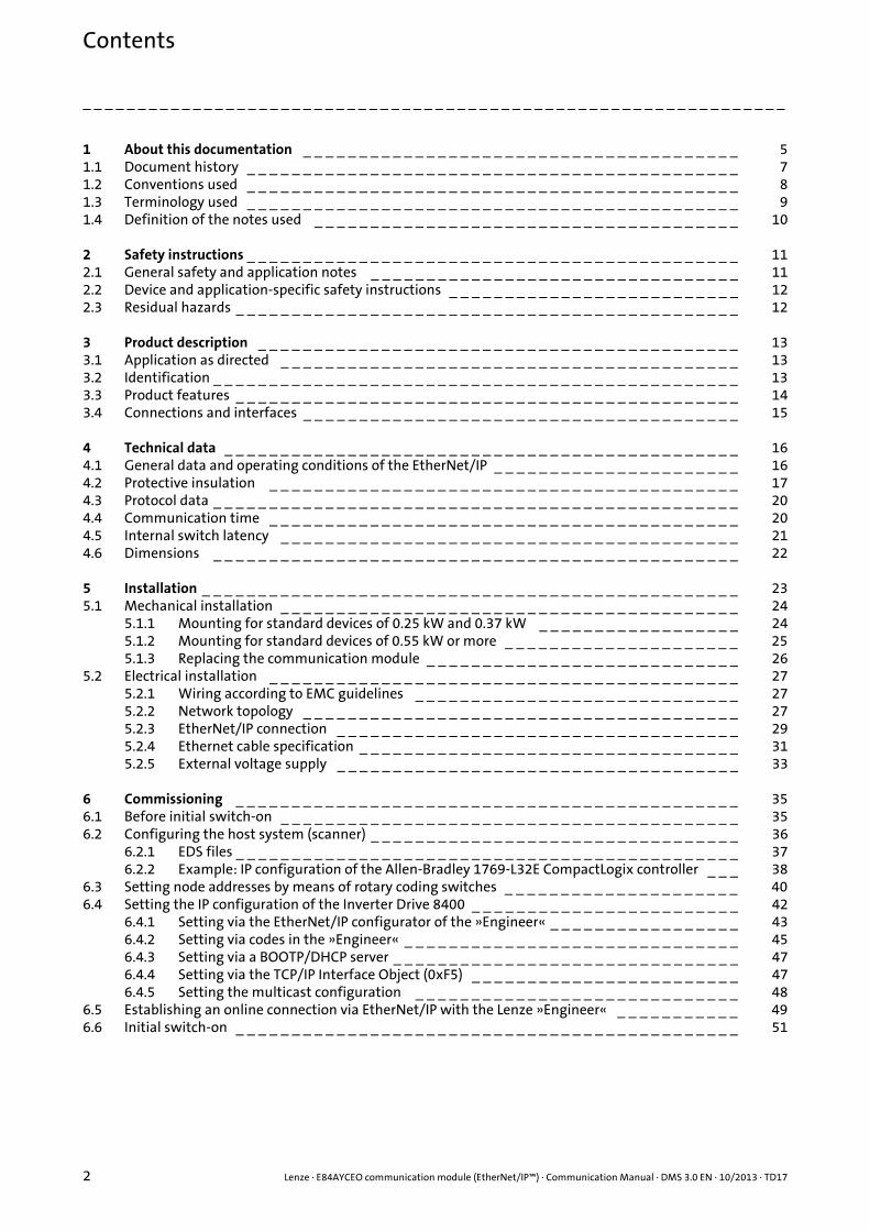
1 About this documentation _ _ _ _ _ _ _ _ _ _ _ _ _ _ _ _ _ _ _ _ _ _ _ _ _ _ _ _ _ _ _ _ _ _ _ _ _ _ _ 51.1 Document history _ _ _ _ _ _ _ _ _ _ _ _ _ _ _ _ _ _ _ _ _ _ _ _ _ _ _ _ _ _ _ _ _ _ _ _ _ _ _ _ _ _ _ _ 71.2 Conventions used _ _ _ _ _ _ _ _ _ _ _ _ _ _ _ _ _ _ _ _ _ _ _ _ _ _ _ _ _ _ _ _ _ _ _ _ _ _ _ _ _ _ _ _ 81.3 Terminology used _ _ _ _ _ _ _ _ _ _ _ _ _ _ _ _ _ _ _ _ _ _ _ _ _ _ _ _ _ _ _ _ _ _ _ _ _ _ _ _ _ _ _ _ 91.4 Definition of the notes used _ _ _ _ _ _ _ _ _ _ _ _ _ _ _ _ _ _ _ _ _ _ _ _ _ _ _ _ _ _ _ _ _ _ _ _ _ _ 10
2 Safety instructions _ _ _ _ _ _ _ _ _ _ _ _ _ _ _ _ _ _ _ _ _ _ _ _ _ _ _ _ _ _ _ _ _ _ _ _ _ _ _ _ _ _ _ _ 112.1 General safety and application notes _ _ _ _ _ _ _ _ _ _ _ _ _ _ _ _ _ _ _ _ _ _ _ _ _ _ _ _ _ _ _ _ _ 112.2 Device and application-specific safety instructions _ _ _ _ _ _ _ _ _ _ _ _ _ _ _ _ _ _ _ _ _ _ _ _ _ _ 122.3 Residual hazards _ _ _ _ _ _ _ _ _ _ _ _ _ _ _ _ _ _ _ _ _ _ _ _ _ _ _ _ _ _ _ _ _ _ _ _ _ _ _ _ _ _ _ _ _ 12
3 Product description _ _ _ _ _ _ _ _ _ _ _ _ _ _ _ _ _ _ _ _ _ _ _ _ _ _ _ _ _ _ _ _ _ _ _ _ _ _ _ _ _ _ _ 133.1 Application as directed _ _ _ _ _ _ _ _ _ _ _ _ _ _ _ _ _ _ _ _ _ _ _ _ _ _ _ _ _ _ _ _ _ _ _ _ _ _ _ _ _ 133.2 Identification _ _ _ _ _ _ _ _ _ _ _ _ _ _ _ _ _ _ _ _ _ _ _ _ _ _ _ _ _ _ _ _ _ _ _ _ _ _ _ _ _ _ _ _ _ _ _ 133.3 Product features _ _ _ _ _ _ _ _ _ _ _ _ _ _ _ _ _ _ _ _ _ _ _ _ _ _ _ _ _ _ _ _ _ _ _ _ _ _ _ _ _ _ _ _ _ 143.4 Connections and interfaces _ _ _ _ _ _ _ _ _ _ _ _ _ _ _ _ _ _ _ _ _ _ _ _ _ _ _ _ _ _ _ _ _ _ _ _ _ _ _ 15
4 Technical data _ _ _ _ _ _ _ _ _ _ _ _ _ _ _ _ _ _ _ _ _ _ _ _ _ _ _ _ _ _ _ _ _ _ _ _ _ _ _ _ _ _ _ _ _ _ 164.1 General data and operating conditions of the EtherNet/IP _ _ _ _ _ _ _ _ _ _ _ _ _ _ _ _ _ _ _ _ _ _ 164.2 Protective insulation _ _ _ _ _ _ _ _ _ _ _ _ _ _ _ _ _ _ _ _ _ _ _ _ _ _ _ _ _ _ _ _ _ _ _ _ _ _ _ _ _ _ 174.3 Protocol data _ _ _ _ _ _ _ _ _ _ _ _ _ _ _ _ _ _ _ _ _ _ _ _ _ _ _ _ _ _ _ _ _ _ _ _ _ _ _ _ _ _ _ _ _ _ _ 204.4 Communication time _ _ _ _ _ _ _ _ _ _ _ _ _ _ _ _ _ _ _ _ _ _ _ _ _ _ _ _ _ _ _ _ _ _ _ _ _ _ _ _ _ _ 204.5 Internal switch latency _ _ _ _ _ _ _ _ _ _ _ _ _ _ _ _ _ _ _ _ _ _ _ _ _ _ _ _ _ _ _ _ _ _ _ _ _ _ _ _ _ 214.6 Dimensions _ _ _ _ _ _ _ _ _ _ _ _ _ _ _ _ _ _ _ _ _ _ _ _ _ _ _ _ _ _ _ _ _ _ _ _ _ _ _ _ _ _ _ _ _ _ _ 22
5 Installation _ _ _ _ _ _ _ _ _ _ _ _ _ _ _ _ _ _ _ _ _ _ _ _ _ _ _ _ _ _ _ _ _ _ _ _ _ _ _ _ _ _ _ _ _ _ _ _ 235.1 Mechanical installation _ _ _ _ _ _ _ _ _ _ _ _ _ _ _ _ _ _ _ _ _ _ _ _ _ _ _ _ _ _ _ _ _ _ _ _ _ _ _ _ _ 24
5.1.1 Mounting for standard devices of 0.25 kW and 0.37 kW _ _ _ _ _ _ _ _ _ _ _ _ _ _ _ _ _ _ 245.1.2 Mounting for standard devices of 0.55 kW or more _ _ _ _ _ _ _ _ _ _ _ _ _ _ _ _ _ _ _ _ _ 255.1.3 Replacing the communication module _ _ _ _ _ _ _ _ _ _ _ _ _ _ _ _ _ _ _ _ _ _ _ _ _ _ _ _ 26
5.2 Electrical installation _ _ _ _ _ _ _ _ _ _ _ _ _ _ _ _ _ _ _ _ _ _ _ _ _ _ _ _ _ _ _ _ _ _ _ _ _ _ _ _ _ _ 275.2.1 Wiring according to EMC guidelines _ _ _ _ _ _ _ _ _ _ _ _ _ _ _ _ _ _ _ _ _ _ _ _ _ _ _ _ _ 275.2.2 Network topology _ _ _ _ _ _ _ _ _ _ _ _ _ _ _ _ _ _ _ _ _ _ _ _ _ _ _ _ _ _ _ _ _ _ _ _ _ _ _ 275.2.3 EtherNet/IP connection _ _ _ _ _ _ _ _ _ _ _ _ _ _ _ _ _ _ _ _ _ _ _ _ _ _ _ _ _ _ _ _ _ _ _ _ 295.2.4 Ethernet cable specification _ _ _ _ _ _ _ _ _ _ _ _ _ _ _ _ _ _ _ _ _ _ _ _ _ _ _ _ _ _ _ _ _ _ 315.2.5 External voltage supply _ _ _ _ _ _ _ _ _ _ _ _ _ _ _ _ _ _ _ _ _ _ _ _ _ _ _ _ _ _ _ _ _ _ _ _ 33
6 Commissioning _ _ _ _ _ _ _ _ _ _ _ _ _ _ _ _ _ _ _ _ _ _ _ _ _ _ _ _ _ _ _ _ _ _ _ _ _ _ _ _ _ _ _ _ _ 356.1 Before initial switch-on _ _ _ _ _ _ _ _ _ _ _ _ _ _ _ _ _ _ _ _ _ _ _ _ _ _ _ _ _ _ _ _ _ _ _ _ _ _ _ _ _ 356.2 Configuring the host system (scanner) _ _ _ _ _ _ _ _ _ _ _ _ _ _ _ _ _ _ _ _ _ _ _ _ _ _ _ _ _ _ _ _ _ 36
6.2.1 EDS files _ _ _ _ _ _ _ _ _ _ _ _ _ _ _ _ _ _ _ _ _ _ _ _ _ _ _ _ _ _ _ _ _ _ _ _ _ _ _ _ _ _ _ _ _ 376.2.2 Example: IP configuration of the Allen-Bradley 1769-L32E CompactLogix controller _ _ _ 38
6.3 Setting node addresses by means of rotary coding switches _ _ _ _ _ _ _ _ _ _ _ _ _ _ _ _ _ _ _ _ _ 406.4 Setting the IP configuration of the Inverter Drive 8400 _ _ _ _ _ _ _ _ _ _ _ _ _ _ _ _ _ _ _ _ _ _ _ _ 42
6.4.1 Setting via the EtherNet/IP configurator of the »Engineer« _ _ _ _ _ _ _ _ _ _ _ _ _ _ _ _ _ 436.4.2 Setting via codes in the »Engineer« _ _ _ _ _ _ _ _ _ _ _ _ _ _ _ _ _ _ _ _ _ _ _ _ _ _ _ _ _ _ 456.4.3 Setting via a BOOTP/DHCP server _ _ _ _ _ _ _ _ _ _ _ _ _ _ _ _ _ _ _ _ _ _ _ _ _ _ _ _ _ _ _ 476.4.4 Setting via the TCP/IP Interface Object (0xF5) _ _ _ _ _ _ _ _ _ _ _ _ _ _ _ _ _ _ _ _ _ _ _ _ 476.4.5 Setting the multicast configuration _ _ _ _ _ _ _ _ _ _ _ _ _ _ _ _ _ _ _ _ _ _ _ _ _ _ _ _ _ 48
6.5 Establishing an online connection via EtherNet/IP with the Lenze »Engineer« _ _ _ _ _ _ _ _ _ _ _ 496.6 Initial switch-on _ _ _ _ _ _ _ _ _ _ _ _ _ _ _ _ _ _ _ _ _ _ _ _ _ _ _ _ _ _ _ _ _ _ _ _ _ _ _ _ _ _ _ _ _ 51
Contents

Lenze · E84AYCEO communication module (EtherNet/IP™) · Communication Manual · DMS 3.0 EN · 10/2013 · TD17 3
Contents
_ _ _ _ _ _ _ _ _ _ _ _ _ _ _ _ _ _ _ _ _ _ _ _ _ _ _ _ _ _ _ _ _ _ _ _ _ _ _ _ _ _ _ _ _ _ _ _ _ _ _ _ _ _ _ _ _ _ _ _ _ _ _ _
7 Data transfer _ _ _ _ _ _ _ _ _ _ _ _ _ _ _ _ _ _ _ _ _ _ _ _ _ _ _ _ _ _ _ _ _ _ _ _ _ _ _ _ _ _ _ _ _ _ _ 527.1 Communication channels _ _ _ _ _ _ _ _ _ _ _ _ _ _ _ _ _ _ _ _ _ _ _ _ _ _ _ _ _ _ _ _ _ _ _ _ _ _ _ _ 537.2 Telegram types _ _ _ _ _ _ _ _ _ _ _ _ _ _ _ _ _ _ _ _ _ _ _ _ _ _ _ _ _ _ _ _ _ _ _ _ _ _ _ _ _ _ _ _ _ 547.3 EtherNet/IP state diagram _ _ _ _ _ _ _ _ _ _ _ _ _ _ _ _ _ _ _ _ _ _ _ _ _ _ _ _ _ _ _ _ _ _ _ _ _ _ _ 55
8 I/O data transfer (implicit messages) _ _ _ _ _ _ _ _ _ _ _ _ _ _ _ _ _ _ _ _ _ _ _ _ _ _ _ _ _ _ _ _ _ 568.1 I/O data mapping _ _ _ _ _ _ _ _ _ _ _ _ _ _ _ _ _ _ _ _ _ _ _ _ _ _ _ _ _ _ _ _ _ _ _ _ _ _ _ _ _ _ _ _ 578.2 Technology applications (TA) / drive profiles _ _ _ _ _ _ _ _ _ _ _ _ _ _ _ _ _ _ _ _ _ _ _ _ _ _ _ _ _ 58
8.2.1 Lenze technology applications / user-definable parameter sets _ _ _ _ _ _ _ _ _ _ _ _ _ _ 588.2.2 "AC Drive Profile" application _ _ _ _ _ _ _ _ _ _ _ _ _ _ _ _ _ _ _ _ _ _ _ _ _ _ _ _ _ _ _ _ _ 59
8.3 I/O assemblies _ _ _ _ _ _ _ _ _ _ _ _ _ _ _ _ _ _ _ _ _ _ _ _ _ _ _ _ _ _ _ _ _ _ _ _ _ _ _ _ _ _ _ _ _ _ 608.4 I/O configuration in the »Engineer« _ _ _ _ _ _ _ _ _ _ _ _ _ _ _ _ _ _ _ _ _ _ _ _ _ _ _ _ _ _ _ _ _ _ 62
8.4.1 Lenze technology application / configuring user-definable parameter sets _ _ _ _ _ _ _ _ 628.4.2 Configuring "AC Drive Profile" application _ _ _ _ _ _ _ _ _ _ _ _ _ _ _ _ _ _ _ _ _ _ _ _ _ _ 67
8.5 I/O configuration with »RSLogix 5000« version 19 or lower _ _ _ _ _ _ _ _ _ _ _ _ _ _ _ _ _ _ _ _ _ 688.6 I/O configuration with »RSLogix 5000« version 20 or higher _ _ _ _ _ _ _ _ _ _ _ _ _ _ _ _ _ _ _ _ _ 738.7 Saving the I/O configuration in »RSLogix 5000« _ _ _ _ _ _ _ _ _ _ _ _ _ _ _ _ _ _ _ _ _ _ _ _ _ _ _ _ 83
9 Parameter data transfer (explicit messages) _ _ _ _ _ _ _ _ _ _ _ _ _ _ _ _ _ _ _ _ _ _ _ _ _ _ _ _ _ _ 849.1 Write parameters _ _ _ _ _ _ _ _ _ _ _ _ _ _ _ _ _ _ _ _ _ _ _ _ _ _ _ _ _ _ _ _ _ _ _ _ _ _ _ _ _ _ _ _ 859.2 Read parameters _ _ _ _ _ _ _ _ _ _ _ _ _ _ _ _ _ _ _ _ _ _ _ _ _ _ _ _ _ _ _ _ _ _ _ _ _ _ _ _ _ _ _ _ _ 86
10 Monitoring _ _ _ _ _ _ _ _ _ _ _ _ _ _ _ _ _ _ _ _ _ _ _ _ _ _ _ _ _ _ _ _ _ _ _ _ _ _ _ _ _ _ _ _ _ _ _ _ 88
11 Diagnostics _ _ _ _ _ _ _ _ _ _ _ _ _ _ _ _ _ _ _ _ _ _ _ _ _ _ _ _ _ _ _ _ _ _ _ _ _ _ _ _ _ _ _ _ _ _ _ _ 8911.1 LED status displays _ _ _ _ _ _ _ _ _ _ _ _ _ _ _ _ _ _ _ _ _ _ _ _ _ _ _ _ _ _ _ _ _ _ _ _ _ _ _ _ _ _ _ 89
11.1.1 Module status displays _ _ _ _ _ _ _ _ _ _ _ _ _ _ _ _ _ _ _ _ _ _ _ _ _ _ _ _ _ _ _ _ _ _ _ _ 9011.1.2 CIP™ status displays _ _ _ _ _ _ _ _ _ _ _ _ _ _ _ _ _ _ _ _ _ _ _ _ _ _ _ _ _ _ _ _ _ _ _ _ _ _ 9111.1.3 Status indicators at the RJ45 sockets (X259, X260) _ _ _ _ _ _ _ _ _ _ _ _ _ _ _ _ _ _ _ _ _ 94
11.2 Diagnostics with the »Engineer« _ _ _ _ _ _ _ _ _ _ _ _ _ _ _ _ _ _ _ _ _ _ _ _ _ _ _ _ _ _ _ _ _ _ _ _ 95
12 Error messages _ _ _ _ _ _ _ _ _ _ _ _ _ _ _ _ _ _ _ _ _ _ _ _ _ _ _ _ _ _ _ _ _ _ _ _ _ _ _ _ _ _ _ _ _ _ 9612.1 Short overview of the EtherNet/IP error messages _ _ _ _ _ _ _ _ _ _ _ _ _ _ _ _ _ _ _ _ _ _ _ _ _ _ 9612.2 Possible causes and remedies _ _ _ _ _ _ _ _ _ _ _ _ _ _ _ _ _ _ _ _ _ _ _ _ _ _ _ _ _ _ _ _ _ _ _ _ _ _ 9712.3 CIP™ error messages _ _ _ _ _ _ _ _ _ _ _ _ _ _ _ _ _ _ _ _ _ _ _ _ _ _ _ _ _ _ _ _ _ _ _ _ _ _ _ _ _ _ _ 10112.4 Mapping of Lenze device errors to DRIVECOM errors _ _ _ _ _ _ _ _ _ _ _ _ _ _ _ _ _ _ _ _ _ _ _ _ _ 102
13 Parameter reference _ _ _ _ _ _ _ _ _ _ _ _ _ _ _ _ _ _ _ _ _ _ _ _ _ _ _ _ _ _ _ _ _ _ _ _ _ _ _ _ _ _ _ 10613.1 Parameters of the communication module _ _ _ _ _ _ _ _ _ _ _ _ _ _ _ _ _ _ _ _ _ _ _ _ _ _ _ _ _ _ 10613.2 Table of attributes _ _ _ _ _ _ _ _ _ _ _ _ _ _ _ _ _ _ _ _ _ _ _ _ _ _ _ _ _ _ _ _ _ _ _ _ _ _ _ _ _ _ _ _ 122

Contents
4 Lenze · E84AYCEO communication module (EtherNet/IP™) · Communication Manual · DMS 3.0 EN · 10/2013 · TD17
_ _ _ _ _ _ _ _ _ _ _ _ _ _ _ _ _ _ _ _ _ _ _ _ _ _ _ _ _ _ _ _ _ _ _ _ _ _ _ _ _ _ _ _ _ _ _ _ _ _ _ _ _ _ _ _ _ _ _ _ _ _ _ _
14 Implemented CIP™ objects _ _ _ _ _ _ _ _ _ _ _ _ _ _ _ _ _ _ _ _ _ _ _ _ _ _ _ _ _ _ _ _ _ _ _ _ _ _ _ 12414.1 General CIP objects _ _ _ _ _ _ _ _ _ _ _ _ _ _ _ _ _ _ _ _ _ _ _ _ _ _ _ _ _ _ _ _ _ _ _ _ _ _ _ _ _ _ _ 126
14.1.1 Identity Object (1 / 0x01) _ _ _ _ _ _ _ _ _ _ _ _ _ _ _ _ _ _ _ _ _ _ _ _ _ _ _ _ _ _ _ _ _ _ _ 12614.1.2 Message Router Object (2 / 0x02) _ _ _ _ _ _ _ _ _ _ _ _ _ _ _ _ _ _ _ _ _ _ _ _ _ _ _ _ _ _ _ 12814.1.3 Assembly Object (4 / 0x04) _ _ _ _ _ _ _ _ _ _ _ _ _ _ _ _ _ _ _ _ _ _ _ _ _ _ _ _ _ _ _ _ _ _ 12914.1.4 Connection Manager Object (6 / 0x06) _ _ _ _ _ _ _ _ _ _ _ _ _ _ _ _ _ _ _ _ _ _ _ _ _ _ _ _ 135
14.2 EtherNet/IP objects _ _ _ _ _ _ _ _ _ _ _ _ _ _ _ _ _ _ _ _ _ _ _ _ _ _ _ _ _ _ _ _ _ _ _ _ _ _ _ _ _ _ _ 13714.2.1 Device Level Ring (DLR) Object (71 / 0x47) _ _ _ _ _ _ _ _ _ _ _ _ _ _ _ _ _ _ _ _ _ _ _ _ _ _ 13714.2.2 Quality of Service (QoS) Object (72 / 0x48) _ _ _ _ _ _ _ _ _ _ _ _ _ _ _ _ _ _ _ _ _ _ _ _ _ _ 13914.2.3 TCP/IP Interface Object (245 / 0xF5) _ _ _ _ _ _ _ _ _ _ _ _ _ _ _ _ _ _ _ _ _ _ _ _ _ _ _ _ _ 14114.2.4 Ethernet Link Object (246 / 0xF6) _ _ _ _ _ _ _ _ _ _ _ _ _ _ _ _ _ _ _ _ _ _ _ _ _ _ _ _ _ _ _ 145
14.3 "AC Drive Profile" objects _ _ _ _ _ _ _ _ _ _ _ _ _ _ _ _ _ _ _ _ _ _ _ _ _ _ _ _ _ _ _ _ _ _ _ _ _ _ _ _ 14814.3.1 Motor Data Object (40 / 0x28) _ _ _ _ _ _ _ _ _ _ _ _ _ _ _ _ _ _ _ _ _ _ _ _ _ _ _ _ _ _ _ _ 14914.3.2 Control Supervisor Object (41 / 0x29) _ _ _ _ _ _ _ _ _ _ _ _ _ _ _ _ _ _ _ _ _ _ _ _ _ _ _ _ 15014.3.3 AC Drive Object (42 / 0x2A) _ _ _ _ _ _ _ _ _ _ _ _ _ _ _ _ _ _ _ _ _ _ _ _ _ _ _ _ _ _ _ _ _ _ 15214.3.4 Write "DriveMode" attribute _ _ _ _ _ _ _ _ _ _ _ _ _ _ _ _ _ _ _ _ _ _ _ _ _ _ _ _ _ _ _ _ _ 154
14.4 Lenze objects _ _ _ _ _ _ _ _ _ _ _ _ _ _ _ _ _ _ _ _ _ _ _ _ _ _ _ _ _ _ _ _ _ _ _ _ _ _ _ _ _ _ _ _ _ _ _ 15514.4.1 Lenze Class (101 / 0x65) _ _ _ _ _ _ _ _ _ _ _ _ _ _ _ _ _ _ _ _ _ _ _ _ _ _ _ _ _ _ _ _ _ _ _ _ 15514.4.2 Lenze Class (103 / 0x67) _ _ _ _ _ _ _ _ _ _ _ _ _ _ _ _ _ _ _ _ _ _ _ _ _ _ _ _ _ _ _ _ _ _ _ _ 15714.4.3 Lenze Class (104 / 0x68) _ _ _ _ _ _ _ _ _ _ _ _ _ _ _ _ _ _ _ _ _ _ _ _ _ _ _ _ _ _ _ _ _ _ _ _ 15814.4.4 Lenze Class (110 / 0x6E) _ _ _ _ _ _ _ _ _ _ _ _ _ _ _ _ _ _ _ _ _ _ _ _ _ _ _ _ _ _ _ _ _ _ _ _ 159
Index _ _ _ _ _ _ _ _ _ _ _ _ _ _ _ _ _ _ _ _ _ _ _ _ _ _ _ _ _ _ _ _ _ _ _ _ _ _ _ _ _ _ _ _ _ _ _ _ _ _ _ 160
Your opinion is important to us _ _ _ _ _ _ _ _ _ _ _ _ _ _ _ _ _ _ _ _ _ _ _ _ _ _ _ _ _ _ _ _ _ _ _ _ _ 164

Lenze · E84AYCEO communication module (EtherNet/IP™) · Communication Manual · DMS 3.0 EN · 10/2013 · TD17 5
1 About this documentation
_ _ _ _ _ _ _ _ _ _ _ _ _ _ _ _ _ _ _ _ _ _ _ _ _ _ _ _ _ _ _ _ _ _ _ _ _ _ _ _ _ _ _ _ _ _ _ _ _ _ _ _ _ _ _ _ _ _ _ _ _ _ _ _
1 About this documentation
Contents
This documentation only contains descriptions of the E84AYCEO (EtherNet/IP™) communicationmodule.
The features and functions of the communication module are described in detail.
Examples illustrate typical applications.
The theoretical context is only explained as far as it is required for understanding the function ofthe communication module.
This documentation does not describe the software of another manufacturer. Noguarantee can be given for corresponding information in this documentation. Informationon the use of the software can be found in the documents for the host (PLC, scanner).
All brand names mentioned in this documentation are trademarks of their corresponding owners.
Tip!
Detailed information on EtherNet/IP can be found on the website of the user organisationODVA (Open DeviceNet Vendor Association):
www.odva.org
Note!
This documentation supplements the mounting instructions supplied with the communication module and the hardware manual "Inverter Drives 8400".
The hardware manual contains safety instructions that must be observed!

1 About this documentation
6 Lenze · E84AYCEO communication module (EtherNet/IP™) · Communication Manual · DMS 3.0 EN · 10/2013 · TD17
_ _ _ _ _ _ _ _ _ _ _ _ _ _ _ _ _ _ _ _ _ _ _ _ _ _ _ _ _ _ _ _ _ _ _ _ _ _ _ _ _ _ _ _ _ _ _ _ _ _ _ _ _ _ _ _ _ _ _ _ _ _ _ _
Target group
This documentation is intended for all persons who plan, install, commission and maintain thenetworking and remote servicing of a machine.
Tip!
Current documentation and software updates with regard to Lenze products can be foundin the download area at:
www.Lenze.com
Information regarding the validity
The information given in this documentation is valid for the following devices:
From software version 01.02, the "AC Drive Profile" of the Inverter Drives 8400 is supported fromversion V13.00.
Screenshots/application examples
All screenshots in this documentation are application examples. Depending on the firmwareversion of the communication module and software version of the installed engineering tools(»Engineer«, »RSLogix 5000«), the screenshots in this documentation may differ from the screenrepresentation.
Extension module Type designation From hardware version
From software version
Communication module EtherNet/IP E84AYCEO VA 01.01
Lenze · E84AYCEO communication module (EtherNet/IP™) · Communication Manual · DMS 3.0 EN · 10/2013 · TD17 7
1 About this documentation1.1 Document history
_ _ _ _ _ _ _ _ _ _ _ _ _ _ _ _ _ _ _ _ _ _ _ _ _ _ _ _ _ _ _ _ _ _ _ _ _ _ _ _ _ _ _ _ _ _ _ _ _ _ _ _ _ _ _ _ _ _ _ _ _ _ _ _
1.1 Document history
Version Description
1.0 08/2012 TD17 First edition
2.0 12/2012 TD17 • Revision for software version 01.02• New layout
3.0 10/2013 TD17 Revised chapters:I/O data transfer (implicit messages) ( 56)Parameter data transfer (explicit messages) ( 84)Implemented CIP™ objects ( 124)

1 About this documentation1.2 Conventions used
8 Lenze · E84AYCEO communication module (EtherNet/IP™) · Communication Manual · DMS 3.0 EN · 10/2013 · TD17
_ _ _ _ _ _ _ _ _ _ _ _ _ _ _ _ _ _ _ _ _ _ _ _ _ _ _ _ _ _ _ _ _ _ _ _ _ _ _ _ _ _ _ _ _ _ _ _ _ _ _ _ _ _ _ _ _ _ _ _ _ _ _ _
1.2 Conventions used
This documentation uses the following conventions to distinguish between different types ofinformation:
Type of information Writing Examples/notes
Spelling of numbers
Decimal separator Point The decimal point is always used.For example: 1234.56
Hexadecimal 0x[0 ... 9, A ... F] Example: 0x60F4
Binary• Nibble
In inverted commasPoint
Example: ’100’Example: ’0110.0100’
Text
Version information Blue text colour All information that applies to from a certain software version of the drive onwards are marked accordingly in this documentation.Example: This function extension is available from software version V3.0 onwards!
Program name » « The Lenze PC software »Engineer«...
Window italics The Message window... / The dialog box Options...
Variable names By setting bEnable to TRUE...
Control element bold The OK button... / the Copy command... / the Characteristics tab... / the Name input field...
Sequence of menu commands
If several commands are required to execute one function, the single commands are separated by an arrow: Select the File Open command to...
Hyperlink underlined Optically highlighted reference to another topic. It is activated with a mouse-click in this online documentation.
Icons
Page reference ( 9) Optically highlighted reference to another page. In this online documentation activated via mouse-click.
Step-by-step instructions Step-by-step instructions are indicated by a pictograph.
Lenze · E84AYCEO communication module (EtherNet/IP™) · Communication Manual · DMS 3.0 EN · 10/2013 · TD17 9
1 About this documentation1.3 Terminology used
_ _ _ _ _ _ _ _ _ _ _ _ _ _ _ _ _ _ _ _ _ _ _ _ _ _ _ _ _ _ _ _ _ _ _ _ _ _ _ _ _ _ _ _ _ _ _ _ _ _ _ _ _ _ _ _ _ _ _ _ _ _ _ _
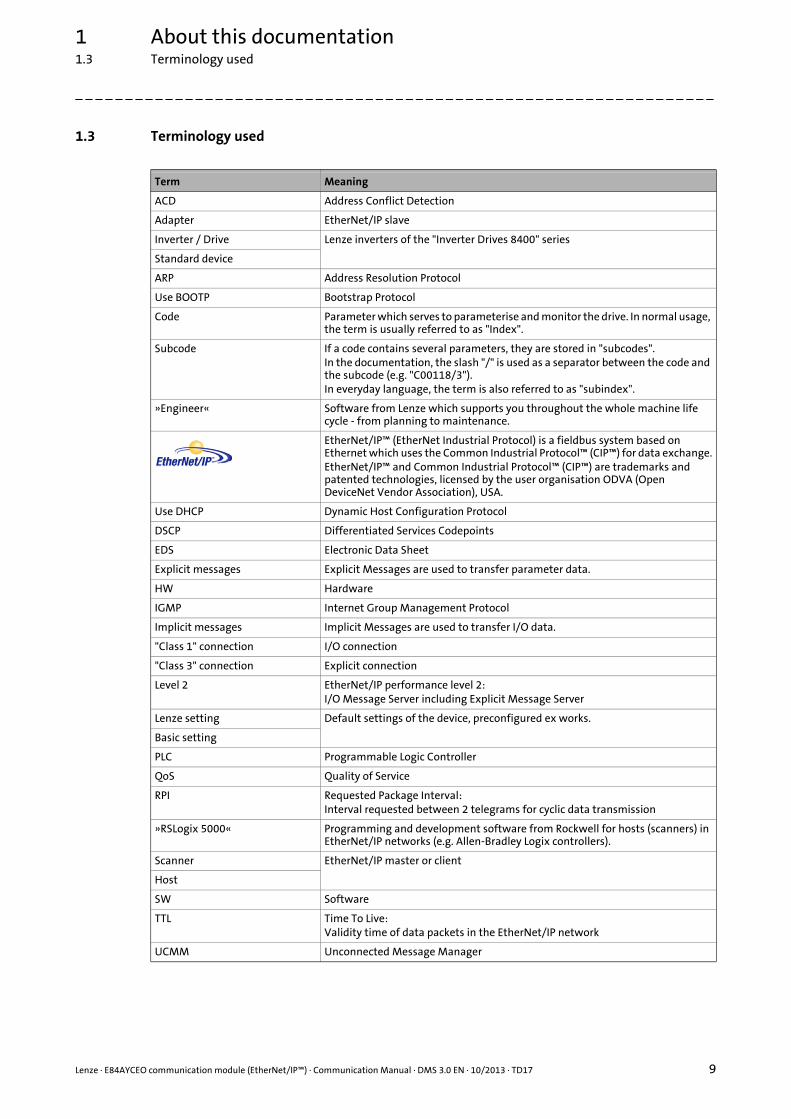
1.3 Terminology used
Term Meaning
ACD Address Conflict Detection
Adapter EtherNet/IP slave
Inverter / Drive Lenze inverters of the "Inverter Drives 8400" series
Standard device
ARP Address Resolution Protocol
Use BOOTP Bootstrap Protocol
Code Parameter which serves to parameterise and monitor the drive. In normal usage, the term is usually referred to as "Index".
Subcode If a code contains several parameters, they are stored in "subcodes".In the documentation, the slash "/" is used as a separator between the code and the subcode (e.g. "C00118/3").In everyday language, the term is also referred to as "subindex".
»Engineer« Software from Lenze which supports you throughout the whole machine life cycle - from planning to maintenance.
EtherNet/IP™ (EtherNet Industrial Protocol) is a fieldbus system based on Ethernet which uses the Common Industrial Protocol™ (CIP™) for data exchange.EtherNet/IP™ and Common Industrial Protocol™ (CIP™) are trademarks and patented technologies, licensed by the user organisation ODVA (Open DeviceNet Vendor Association), USA.
Use DHCP Dynamic Host Configuration Protocol
DSCP Differentiated Services Codepoints
EDS Electronic Data Sheet
Explicit messages Explicit Messages are used to transfer parameter data.
HW Hardware
IGMP Internet Group Management Protocol
Implicit messages Implicit Messages are used to transfer I/O data.
"Class 1" connection I/O connection
"Class 3" connection Explicit connection
Level 2 EtherNet/IP performance level 2:I/O Message Server including Explicit Message Server
Lenze setting Default settings of the device, preconfigured ex works.
Basic setting
PLC Programmable Logic Controller
QoS Quality of Service
RPI Requested Package Interval:Interval requested between 2 telegrams for cyclic data transmission
»RSLogix 5000« Programming and development software from Rockwell for hosts (scanners) in EtherNet/IP networks (e.g. Allen-Bradley Logix controllers).
Scanner EtherNet/IP master or client
Host
SW Software
TTL Time To Live:Validity time of data packets in the EtherNet/IP network
UCMM Unconnected Message Manager

1 About this documentation1.4 Definition of the notes used
10 Lenze · E84AYCEO communication module (EtherNet/IP™) · Communication Manual · DMS 3.0 EN · 10/2013 · TD17
_ _ _ _ _ _ _ _ _ _ _ _ _ _ _ _ _ _ _ _ _ _ _ _ _ _ _ _ _ _ _ _ _ _ _ _ _ _ _ _ _ _ _ _ _ _ _ _ _ _ _ _ _ _ _ _ _ _ _ _ _ _ _ _
1.4 Definition of the notes used
The following signal words and symbols are used in this documentation to indicate dangers andimportant information:
Safety instructions
Layout of the safety instructions:
Application notes
Danger!
(characterises the type and severity of danger)
Note
(describes the danger and gives information about how to prevent dangerous situations)
Pictograph Signal word Meaning
Danger! Danger of personal injury through dangerous electrical voltageReference to an imminent danger that may result in death or serious personal injury if the corresponding measures are not taken.
Danger! Danger of personal injury through a general source of dangerReference to an imminent danger that may result in death or serious personal injury if the corresponding measures are not taken.
Stop! Danger of property damageReference to a possible danger that may result in property damage if the corresponding measures are not taken.
Pictograph Signal word Meaning
Note! Important note to ensure trouble-free operation
Tip! Useful tip for easy handling
Reference to another document

Lenze · E84AYCEO communication module (EtherNet/IP™) · Communication Manual · DMS 3.0 EN · 10/2013 · TD17 11
2 Safety instructions2.1 General safety and application notes
_ _ _ _ _ _ _ _ _ _ _ _ _ _ _ _ _ _ _ _ _ _ _ _ _ _ _ _ _ _ _ _ _ _ _ _ _ _ _ _ _ _ _ _ _ _ _ _ _ _ _ _ _ _ _ _ _ _ _ _ _ _ _ _
2 Safety instructions
2.1 General safety and application notes
Lenze drive and automation components ...
• must only be used as directed.
• must never be commissioned if they display signs of damage.
• must never be technically modified.
• must never be commissioned if they are not fully mounted.
• must never be operated without required covers.
• during and after operation can have live, moving and rotating parts, depending on their degree of protection. Surfaces can be hot.
The following applies to Lenze drive components ...
• only use the accessories approved.
• Only use original manufacturer spare parts.
Observe all specifications contained in the enclosed documentation and related documentation.
• This is the precondition for safe and trouble-free operation and for obtaining the product features specified.Product features ( 14)
• The specifications, processes, and circuitry described in this document are for guidance only and must be adapted to your own specific application. Lenze does not take responsibility for the suitability of the process and circuit proposals.
All works on and with Lenze drive and automation components must only be carried out by qualifiedpersonnel. According to IEC 60364 or CENELEC HD 384 these are persons who ...
• are familiar with installing, mounting, commissioning, and operating the product.
• who have the corresponding qualifications for their work.
• who know and can apply all regulations for the prevention of accidents, directives, and laws applicable at the place of use.
Note!
It is absolutely vital that the stated safety measures are implemented in order to prevent serious injury to persons and damage to material assets.
Always keep this documentation to hand in the vicinity of the product during operation.
Danger!
If the following basic safety measures are disregarded, severe injuries to persons and damage to material assets may result.
2 Safety instructions2.2 Device and application-specific safety instructions
12 Lenze · E84AYCEO communication module (EtherNet/IP™) · Communication Manual · DMS 3.0 EN · 10/2013 · TD17
_ _ _ _ _ _ _ _ _ _ _ _ _ _ _ _ _ _ _ _ _ _ _ _ _ _ _ _ _ _ _ _ _ _ _ _ _ _ _ _ _ _ _ _ _ _ _ _ _ _ _ _ _ _ _ _ _ _ _ _ _ _ _ _
2.2 Device and application-specific safety instructions
• During operation, the communication module must be securely connected to the standard device.
• With external voltage supply, always use a separate power supply unit, safely separated to EN 61800-5-1 in every control cabinet (SELV/PELV).
• Only use cables corresponding to the given specifications.Ethernet cable specification ( 31)
2.3 Residual hazards
Protection of persons
If the Inverter Drives 8400 are used on a phase earthed mains with a rated mains voltage 400 V,protection against accidental contact is not ensured without implementing external measures.Protective insulation ( 17)
Device protection
The communication module contains electronic components which may be damaged or destroyedby electrostatic discharge.Installation ( 23)
Documentation for the standard device, host, system/machine
All the other measures prescribed in this documentation must also be implemented. Observe the safety instructions and application notes contained in this manual.
Lenze · E84AYCEO communication module (EtherNet/IP™) · Communication Manual · DMS 3.0 EN · 10/2013 · TD17 13
3 Product description3.1 Application as directed
_ _ _ _ _ _ _ _ _ _ _ _ _ _ _ _ _ _ _ _ _ _ _ _ _ _ _ _ _ _ _ _ _ _ _ _ _ _ _ _ _ _ _ _ _ _ _ _ _ _ _ _ _ _ _ _ _ _ _ _ _ _ _ _
3 Product description
3.1 Application as directed
The communication module ...
• is an accessory module that can be used in conjunction with the following standard devices:
• is a device intended for use in industrial power systems.
• should only be used under the operating conditions prescribed in this documentation.
• can only be used in EtherNet/IP networks.
Any other use shall be deemed inappropriate!
3.2 Identification
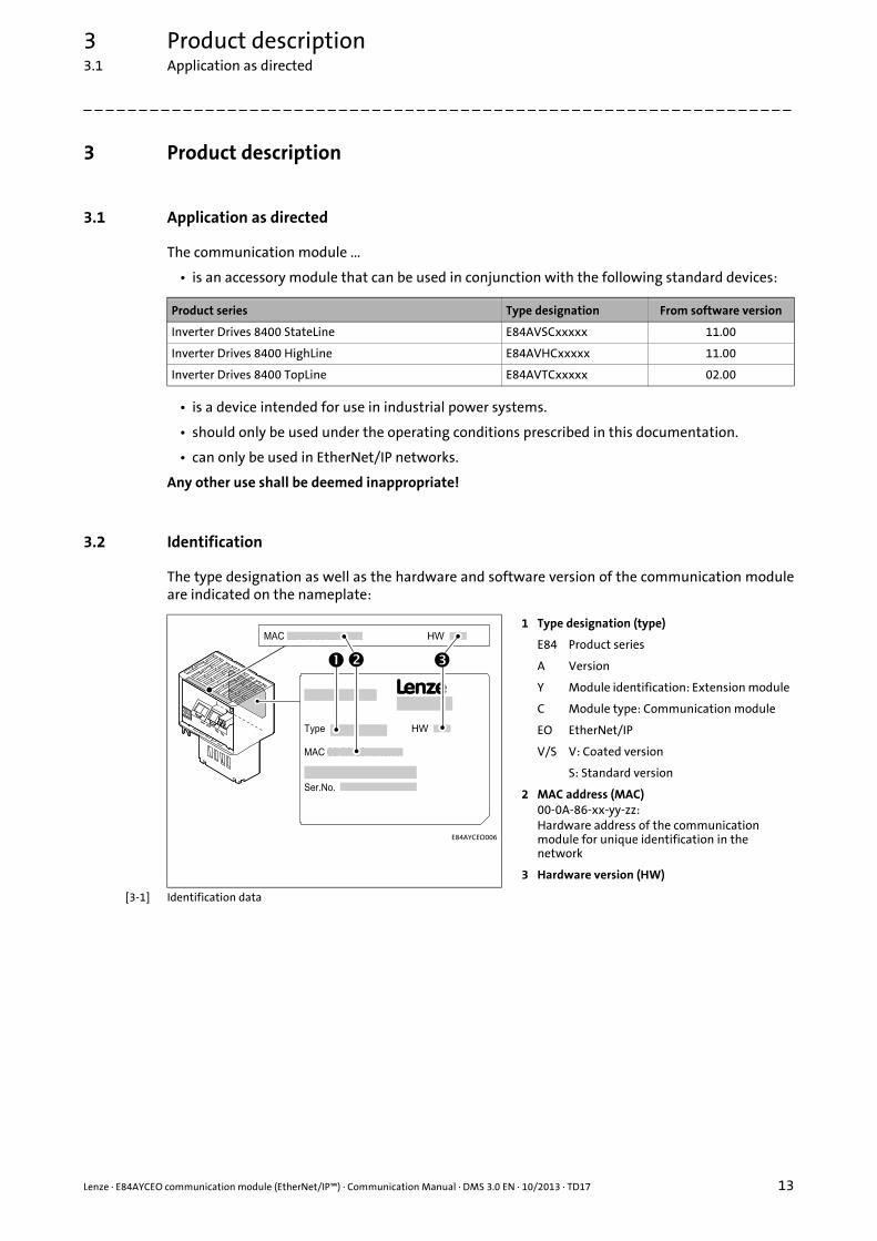
The type designation as well as the hardware and software version of the communication moduleare indicated on the nameplate:
[3-1] Identification data
Product series Type designation From software version
Inverter Drives 8400 StateLine E84AVSCxxxxx 11.00
Inverter Drives 8400 HighLine E84AVHCxxxxx 11.00
Inverter Drives 8400 TopLine E84AVTCxxxxx 02.00
E84AYCEO006
1 Type designation (type)
E84 Product series
A Version
Y Module identification: Extension module
C Module type: Communication module
EO EtherNet/IP
V/S V: Coated version
S: Standard version
2 MAC address (MAC)00-0A-86-xx-yy-zz:Hardware address of the communication module for unique identification in the network
3 Hardware version (HW)
3 Product description3.3 Product features
14 Lenze · E84AYCEO communication module (EtherNet/IP™) · Communication Manual · DMS 3.0 EN · 10/2013 · TD17
_ _ _ _ _ _ _ _ _ _ _ _ _ _ _ _ _ _ _ _ _ _ _ _ _ _ _ _ _ _ _ _ _ _ _ _ _ _ _ _ _ _ _ _ _ _ _ _ _ _ _ _ _ _ _ _ _ _ _ _ _ _ _ _
3.3 Product features
• Interface module for the EtherNet/IP communication system, for attachment to the expansion slots of Inverter Drives 8400
• The communication module can either be supplied internally by the standard device or externally by a separate voltage source.
• The Inverter Drive 8400 is always an adapter device:EtherNet/IP adapter with "Level 2" functionality
• 2-port interface with integrated switch functionality
• Access to all Lenze parameters (configurable via TCP/IP using the Lenze »Engineer«)
• Up to 3 TCP/IP socket connections for communication with the Lenze »Engineer«
• Support of "IP Config Pending" (activation of changed IP configuration by "power off/on" or "type 0 reset")
• Support of the redundancy protocol DLR (Device Level Ring) as "beacon-based ring node"
• Up to 16 I/O data words (32 bytes) are possible.
• Further CIP features:• Max. 8 CIP connections• 1 "exclusive owner" connection• I/O connection type: cyclic• Minimum I/O cycle time: 4 ms• Support of multicast messages, UCMM, ACD, BOOTP/DHCP, VLAN tagging/DSCP
Lenze · E84AYCEO communication module (EtherNet/IP™) · Communication Manual · DMS 3.0 EN · 10/2013 · TD17 15
3 Product description3.4 Connections and interfaces
_ _ _ _ _ _ _ _ _ _ _ _ _ _ _ _ _ _ _ _ _ _ _ _ _ _ _ _ _ _ _ _ _ _ _ _ _ _ _ _ _ _ _ _ _ _ _ _ _ _ _ _ _ _ _ _ _ _ _ _ _ _ _ _
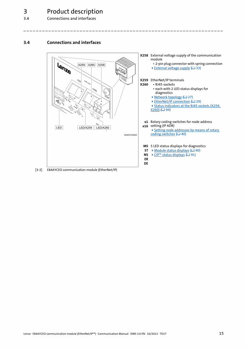
3.4 Connections and interfaces
[3-2] E84AYCEO communication module (EtherNet/IP)
E84AYCEO003
X258 External voltage supply of the communication module
• 2-pin plug connector with spring connectionExternal voltage supply ( 33)
X259X260
EtherNet/IP terminals• RJ45-sockets• each with 2 LED status displays for
diagnosticsNetwork topology ( 27) EtherNet/IP connection ( 29) Status indicators at the RJ45 sockets (X259, X260) ( 94)
x1x16
Rotary coding switches for node address setting (IP ADR)Setting node addresses by means of rotary coding switches ( 40)
MSSTNSERDE
5 LED status displays for diagnosticsModule status displays ( 90) CIP™ status displays ( 91)

4 Technical data4.1 General data and operating conditions of the EtherNet/IP
16 Lenze · E84AYCEO communication module (EtherNet/IP™) · Communication Manual · DMS 3.0 EN · 10/2013 · TD17
_ _ _ _ _ _ _ _ _ _ _ _ _ _ _ _ _ _ _ _ _ _ _ _ _ _ _ _ _ _ _ _ _ _ _ _ _ _ _ _ _ _ _ _ _ _ _ _ _ _ _ _ _ _ _ _ _ _ _ _ _ _ _ _
4 Technical data
4.1 General data and operating conditions of the EtherNet/IP
Range Values
Order designation E84AYCEO
Communication profile EtherNet/IP
Communication medium S/FTP (Screened Foiled Twisted Pair), ISO/IEC 11801 or EN 50173, CAT 5e
Interface for communication RJ45 Standard Ethernet (according to IEEE 802.3), 100Base-TX (Fast Ethernet)
Network topology Tree, star, and line
Type of node Adapter (slave)
Number of nodes Max. 254 in the subnetwork
Max. cable length 100 m
Vendor ID 587 (0x24B), Lenze (’Lenze AC Tech’ in older Rockwell data)
Device type 2 (0x02), AC Drive
Product code 8400 (0x20D0)
Baud rate • 10 Mbps• 100 Mbps
Transmission mode Half duplex / full duplex
Switching method Store-and-forward / cut-through
Switch latency Approx. 125 μs at max. telegram length
Voltage supply External supply via separate power supply unit• + : U = 24 V DC (20.4 ... 28.8 V), Imax = 140 mA• - : Reference potential for external voltage supply
Conformities , approvals • CE• UL
(see also hardware manual)
Hardware manual for Inverter Drives 8400
Here you can find the ambient conditions and data on the electromagnetic compatibility (EMC), which also apply to the communication module.
Lenze · E84AYCEO communication module (EtherNet/IP™) · Communication Manual · DMS 3.0 EN · 10/2013 · TD17 17
4 Technical data4.2 Protective insulation
_ _ _ _ _ _ _ _ _ _ _ _ _ _ _ _ _ _ _ _ _ _ _ _ _ _ _ _ _ _ _ _ _ _ _ _ _ _ _ _ _ _ _ _ _ _ _ _ _ _ _ _ _ _ _ _ _ _ _ _ _ _ _ _
4.2 Protective insulation
Danger!
Dangerous voltage
If the Inverter Drives 8400 are operated on a phase-earthed mains with a rated mains voltage of 400 V, external measures need to be implemented in order to ensure protection against accidental contact.
Possible consequences:
Death or severe injuries
Protective measures:
If protection against accidental contact is required for the control terminals of the inverter and the connections of the plugged device modules, ...• a double isolating distance must exist.• the components to be connected must be provided with the second isolating
distance.
Note!
The existing protective insulation in the Inverter Drives 8400 is implemented according to EN 61800-5-1.

4 Technical data4.2 Protective insulation
18 Lenze · E84AYCEO communication module (EtherNet/IP™) · Communication Manual · DMS 3.0 EN · 10/2013 · TD17
_ _ _ _ _ _ _ _ _ _ _ _ _ _ _ _ _ _ _ _ _ _ _ _ _ _ _ _ _ _ _ _ _ _ _ _ _ _ _ _ _ _ _ _ _ _ _ _ _ _ _ _ _ _ _ _ _ _ _ _ _ _ _ _
The following illustration ...
• shows the arrangement of the terminal strips and the separate potential areas of the Inverter Drive 8400.
• serves to determine the decisive protective insulation between two terminals located in differently insulated separate potential areas.
[4-1] Protective insulation in accordance with EN61800-5-1
E84YCXX007
Reinforced insulation
Basic insulation
Functional insulation
X4
X6
X5
X3
Bus Ext. DC
MCI
X4
X6
X5
X3
X1X1
X105X105
X100X100
MMI
X106X106X106X106
X106X106X106X101
Terminal strip Connection
X100 Mains / DC bus connection
X101 Relay contact
X105 Motor/brake resistor
X106 Motor PTC
X1 System bus (CANopen)
X3 Analog inputs/outputs
X4 Digital outputs
X5 Digital inputs
X6 Diagnostics
MCI Slot for communication module
MMI Slot for the memory module

Lenze · E84AYCEO communication module (EtherNet/IP™) · Communication Manual · DMS 3.0 EN · 10/2013 · TD17 19
4 Technical data4.2 Protective insulation
_ _ _ _ _ _ _ _ _ _ _ _ _ _ _ _ _ _ _ _ _ _ _ _ _ _ _ _ _ _ _ _ _ _ _ _ _ _ _ _ _ _ _ _ _ _ _ _ _ _ _ _ _ _ _ _ _ _ _ _ _ _ _ _
Example
Which type of protective insulation is used between the bus terminal of the device module in slotMCI and the X100 mains terminal?
The separate potential area with the better protective insulation is decisive.
• The separate potential area of the bus terminal of the device module has a "functional insulation".
• The separate potential area of the mains terminal has a "reinforced insulation".
Result: The insulation between mains terminal X100 and the bus terminal is of the "reinforcedinsulation" type.
4 Technical data4.3 Protocol data
20 Lenze · E84AYCEO communication module (EtherNet/IP™) · Communication Manual · DMS 3.0 EN · 10/2013 · TD17
_ _ _ _ _ _ _ _ _ _ _ _ _ _ _ _ _ _ _ _ _ _ _ _ _ _ _ _ _ _ _ _ _ _ _ _ _ _ _ _ _ _ _ _ _ _ _ _ _ _ _ _ _ _ _ _ _ _ _ _ _ _ _ _
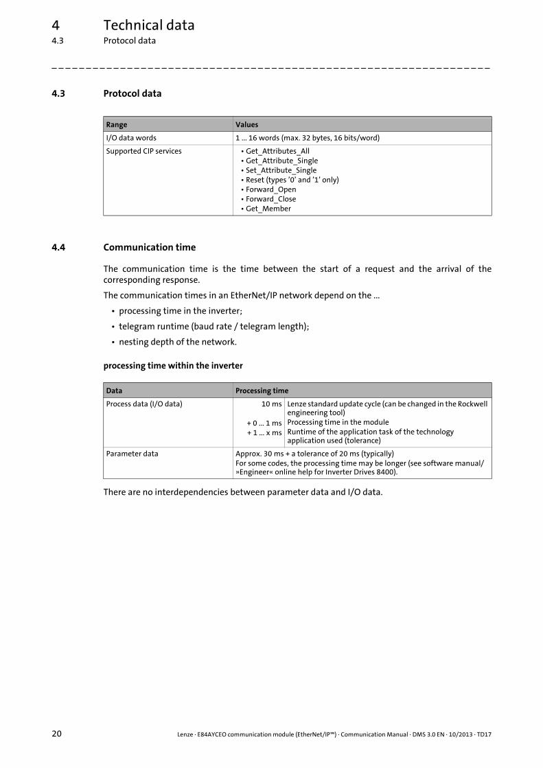
4.3 Protocol data
4.4 Communication time
The communication time is the time between the start of a request and the arrival of thecorresponding response.
The communication times in an EtherNet/IP network depend on the ...
• processing time in the inverter;
• telegram runtime (baud rate / telegram length);
• nesting depth of the network.
processing time within the inverter
There are no interdependencies between parameter data and I/O data.
Range Values
I/O data words 1 ... 16 words (max. 32 bytes, 16 bits/word)
Supported CIP services • Get_Attributes_All• Get_Attribute_Single• Set_Attribute_Single• Reset (types ’0’ and ’1’ only)• Forward_Open• Forward_Close• Get_Member
Data Processing time
Process data (I/O data) 10 ms
+ 0 ... 1 ms+ 1 ... x ms
Lenze standard update cycle (can be changed in the Rockwell engineering tool)Processing time in the moduleRuntime of the application task of the technology application used (tolerance)
Parameter data Approx. 30 ms + a tolerance of 20 ms (typically)For some codes, the processing time may be longer (see software manual/»Engineer« online help for Inverter Drives 8400).

Lenze · E84AYCEO communication module (EtherNet/IP™) · Communication Manual · DMS 3.0 EN · 10/2013 · TD17 21
4 Technical data4.5 Internal switch latency
_ _ _ _ _ _ _ _ _ _ _ _ _ _ _ _ _ _ _ _ _ _ _ _ _ _ _ _ _ _ _ _ _ _ _ _ _ _ _ _ _ _ _ _ _ _ _ _ _ _ _ _ _ _ _ _ _ _ _ _ _ _ _ _
4.5 Internal switch latency
The integrated 2-port switch causes runtime delays. For "store-and-forward" and 100 Mbps, theseruntime delays can be calculated as follows.
Runtime delay for an output data packet of the scanners incl. 32-bit "run/idle header" with 16-bitsequence counter:
Runtime delay for an output data packet of an adapter without 32/bit "run/idle header":
Example
Delay of an output data packet of the scanners with 8 output data words (16 bytes):
• ((66 permanent bytes + 16 bytes) x 8 x 10 nsec) + 4 μsec
• (82 bytes x 8 x 10 nsec) + 4 μsec
• 6.56 μsec + 4 μsec = 10.56 μsec
Runtime delay = ((66 permanent bytes + I/O data in bytes) x 8 x 10 nsec) + 4 μsec
Runtime delay = ((62 permanent bytes + I/O data in bytes) x 8 x 10 nsec) + 4 μsec
Note!
The use of external switches can also lead to runtime delays. Depending on the system constellation, it may be useful to create a star topology or a line/mix topology.
Network topology ( 27)

4 Technical data4.6 Dimensions
22 Lenze · E84AYCEO communication module (EtherNet/IP™) · Communication Manual · DMS 3.0 EN · 10/2013 · TD17
_ _ _ _ _ _ _ _ _ _ _ _ _ _ _ _ _ _ _ _ _ _ _ _ _ _ _ _ _ _ _ _ _ _ _ _ _ _ _ _ _ _ _ _ _ _ _ _ _ _ _ _ _ _ _ _ _ _ _ _ _ _ _ _
4.6 Dimensions
[4-2] Dimensions
E84AYCEO005_1
Type Dimensions [mm]
a b c c1
E84AYCEO 67 50 57 8

Lenze · E84AYCEO communication module (EtherNet/IP™) · Communication Manual · DMS 3.0 EN · 10/2013 · TD17 23
5 Installation
_ _ _ _ _ _ _ _ _ _ _ _ _ _ _ _ _ _ _ _ _ _ _ _ _ _ _ _ _ _ _ _ _ _ _ _ _ _ _ _ _ _ _ _ _ _ _ _ _ _ _ _ _ _ _ _ _ _ _ _ _ _ _ _
5 Installation
Stop!
Electrostatic discharge
Electronic components within the communication module can be damaged or destroyed by electrostatic discharge.
Possible consequences:• The communication module is defective.• Fieldbus communication is not possible or faulty.
Protective measures
Before touching the module, be sure that you are free of electrostatic charge.

5 Installation5.1 Mechanical installation
24 Lenze · E84AYCEO communication module (EtherNet/IP™) · Communication Manual · DMS 3.0 EN · 10/2013 · TD17
_ _ _ _ _ _ _ _ _ _ _ _ _ _ _ _ _ _ _ _ _ _ _ _ _ _ _ _ _ _ _ _ _ _ _ _ _ _ _ _ _ _ _ _ _ _ _ _ _ _ _ _ _ _ _ _ _ _ _ _ _ _ _ _
5.1 Mechanical installation
The communication module can be plugged in or unplugged from the MCI slot when the drive isswitched on. When the module is plugged in, it is detected automatically, and a function andversion plausibility check is executed.
5.1.1 Mounting for standard devices of 0.25 kW and 0.37 kW
[5-1] Mounting for standard devices of 0.25 kW and 0.37 kW
Mounting steps
1. Use a screwdriver to lever out the cover of the MCI slot of the standard device and remove it (1, 2).
2. Loosen the securing screw for the communication module at the standard device (3).
3. Insert the communication module into the MCI slot of the standard device (4).
4. Tighten the securing screw again (5).
E84YCPM002D
Lenze · E84AYCEO communication module (EtherNet/IP™) · Communication Manual · DMS 3.0 EN · 10/2013 · TD17 25
5 Installation5.1 Mechanical installation
_ _ _ _ _ _ _ _ _ _ _ _ _ _ _ _ _ _ _ _ _ _ _ _ _ _ _ _ _ _ _ _ _ _ _ _ _ _ _ _ _ _ _ _ _ _ _ _ _ _ _ _ _ _ _ _ _ _ _ _ _ _ _ _
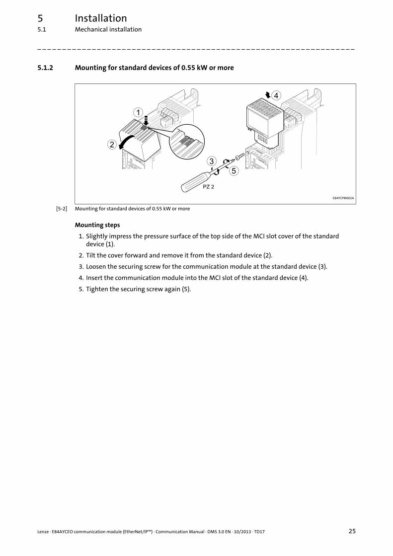
5.1.2 Mounting for standard devices of 0.55 kW or more
[5-2] Mounting for standard devices of 0.55 kW or more
Mounting steps
1. Slightly impress the pressure surface of the top side of the MCI slot cover of the standard device (1).
2. Tilt the cover forward and remove it from the standard device (2).
3. Loosen the securing screw for the communication module at the standard device (3).
4. Insert the communication module into the MCI slot of the standard device (4).
5. Tighten the securing screw again (5).
E84YCPM002A

5 Installation5.1 Mechanical installation
26 Lenze · E84AYCEO communication module (EtherNet/IP™) · Communication Manual · DMS 3.0 EN · 10/2013 · TD17
_ _ _ _ _ _ _ _ _ _ _ _ _ _ _ _ _ _ _ _ _ _ _ _ _ _ _ _ _ _ _ _ _ _ _ _ _ _ _ _ _ _ _ _ _ _ _ _ _ _ _ _ _ _ _ _ _ _ _ _ _ _ _ _
5.1.3 Replacing the communication module
[5-3] Replacing the communication module
Mounting steps
1. Loosen the securing screw for the communication module at the standard device (1).
2. Pull the communication module out of the MCI slot of the standard device (2).
3. Insert the new communication module into the MCI slot of the standard device (3).
4. Tighten the securing screw again (4).
E84YCPM002B

Lenze · E84AYCEO communication module (EtherNet/IP™) · Communication Manual · DMS 3.0 EN · 10/2013 · TD17 27
5 Installation5.2 Electrical installation
_ _ _ _ _ _ _ _ _ _ _ _ _ _ _ _ _ _ _ _ _ _ _ _ _ _ _ _ _ _ _ _ _ _ _ _ _ _ _ _ _ _ _ _ _ _ _ _ _ _ _ _ _ _ _ _ _ _ _ _ _ _ _ _
5.2 Electrical installation
5.2.1 Wiring according to EMC guidelines
In typical systems, standard shielding is sufficient for Ethernet cables.
However, in environments with a very high level of interference, EMC resistance can be improvedby additionally earthing the cable shield on both sides.
For this observe the following notes:
1. Remove the plastic sheath of the cable at a length of 2 cm.
2. Fasten the cable shield to the shield support of the standard device.
5.2.2 Network topology
It is typical of EtherNet/IP to have a rather free topology the limiting factor of which is largemessage latencies due to e.g. switches connected in series.
Internal switch latency ( 21)
The combination of a line and a stub is useful for system wiring.
EtherNet/IP supports the following topologies:
• Line
[5-4] Line topology (S = scanner, A = adapter)
• Switch / star
[5-5] Switch / star topology (SW = switch, A = adapter)
Documentation for the standard device, host, system/machine
Observe the notes and wiring instructions contained in this documentation.
E94AYCEO008
AA
S
AA
E94AYCEO005
SW
AAA

5 Installation5.2 Electrical installation
28 Lenze · E84AYCEO communication module (EtherNet/IP™) · Communication Manual · DMS 3.0 EN · 10/2013 · TD17
_ _ _ _ _ _ _ _ _ _ _ _ _ _ _ _ _ _ _ _ _ _ _ _ _ _ _ _ _ _ _ _ _ _ _ _ _ _ _ _ _ _ _ _ _ _ _ _ _ _ _ _ _ _ _ _ _ _ _ _ _ _ _ _
• Tree via switches
[5-6] Tree topology (S = scanner, SW = switch)
• Switch / switch
[5-7] Switch / switch topology (SW = switch)
E94AYCEO006
S
SWSWSW
E94AYCEO007
SWSWSW

Lenze · E84AYCEO communication module (EtherNet/IP™) · Communication Manual · DMS 3.0 EN · 10/2013 · TD17 29
5 Installation5.2 Electrical installation
_ _ _ _ _ _ _ _ _ _ _ _ _ _ _ _ _ _ _ _ _ _ _ _ _ _ _ _ _ _ _ _ _ _ _ _ _ _ _ _ _ _ _ _ _ _ _ _ _ _ _ _ _ _ _ _ _ _ _ _ _ _ _ _
5.2.3 EtherNet/IP connection
A connection to the EtherNet/IP network is established via RJ45 sockets X259 and X260.
[5-8] EtherNet/IP terminals X259 and X260
For connection of the communication module to the EtherNet/IP fieldbus, a standard Ethernetpatch cable is suitable.
Ethernet cable specification ( 31)
The installation and removal of the Ethernet cables is optimised for the use of connectors inaccordance with the "Automation Initiative of German Domestic Automobile Manufacturers"(AIDA).
E84AYCEO005_2
Note!
To prevent the RJ45 socket from being damaged, insert or remove the Ethernet cable connector straight (at a right angle) into or from the socket.

5 Installation5.2 Electrical installation
30 Lenze · E84AYCEO communication module (EtherNet/IP™) · Communication Manual · DMS 3.0 EN · 10/2013 · TD17
_ _ _ _ _ _ _ _ _ _ _ _ _ _ _ _ _ _ _ _ _ _ _ _ _ _ _ _ _ _ _ _ _ _ _ _ _ _ _ _ _ _ _ _ _ _ _ _ _ _ _ _ _ _ _ _ _ _ _ _ _ _ _ _
Pin assignment of the RJ45 sockets
Tip!
The EtherNet/IP interfaces feature an auto-MDIX function. This function adjusts thepolarity of the RJ45 interfaces so that a connection can be established irrespective of thepolarity of the opposite EtherNet/IP interface and irrespective of the type of cable used(standard patch cable or crossover cable).
RJ45 socket Pin Signal
E94AYCXX004C
1 Tx +
2 Tx -
3 Rx +
4 -
5 -
6 Rx -
7 -
8 -
Note!
Dependent on the configuration of the Ethernet port of the device to be connected, we recommend the use of a cross-over cable.
Lenze · E84AYCEO communication module (EtherNet/IP™) · Communication Manual · DMS 3.0 EN · 10/2013 · TD17 31
5 Installation5.2 Electrical installation
_ _ _ _ _ _ _ _ _ _ _ _ _ _ _ _ _ _ _ _ _ _ _ _ _ _ _ _ _ _ _ _ _ _ _ _ _ _ _ _ _ _ _ _ _ _ _ _ _ _ _ _ _ _ _ _ _ _ _ _ _ _ _ _
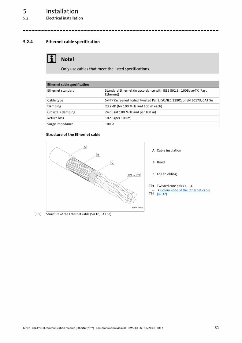
5.2.4 Ethernet cable specification
Structure of the Ethernet cable
[5-9] Structure of the Ethernet cable (S/FTP, CAT 5e)
Note!
Only use cables that meet the listed specifications.
Ethernet cable specification
Ethernet standard Standard Ethernet (in accordance with IEEE 802.3), 100Base-TX (Fast Ethernet)
Cable type S/FTP (Screened Foiled Twisted Pair), ISO/IEC 11801 or EN 50173, CAT 5e
Damping 23.2 dB (for 100 MHz and 100 m each)
Crosstalk damping 24 dB (at 100 MHz and per 100 m)
Return loss 10 dB (per 100 m)
Surge impedance 100
E94YCEP016
A Cable insulation
B Braid
C Foil shielding
TP1...
TP4
Twisted core pairs 1 ... 4Colour code of the Ethernet cable ( 32)
5 Installation5.2 Electrical installation
32 Lenze · E84AYCEO communication module (EtherNet/IP™) · Communication Manual · DMS 3.0 EN · 10/2013 · TD17
_ _ _ _ _ _ _ _ _ _ _ _ _ _ _ _ _ _ _ _ _ _ _ _ _ _ _ _ _ _ _ _ _ _ _ _ _ _ _ _ _ _ _ _ _ _ _ _ _ _ _ _ _ _ _ _ _ _ _ _ _ _ _ _
Colour code of the Ethernet cable
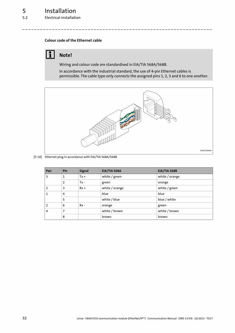
[5-10] Ethernet plug in accordance with EIA/TIA 568A/568B
Note!
Wiring and colour code are standardised in EIA/TIA 568A/568B.
In accordance with the industrial standard, the use of 4-pin Ethernet cables is permissible. The cable type only connects the assigned pins 1, 2, 3 and 6 to one another.
E94YCEI004A
Pair Pin Signal EIA/TIA 568A EIA/TIA 568B
3 1 Tx + white / green white / orange
2 Tx - green orange
2 3 Rx + white / orange white / green
1 4 blue blue
5 white / blue blue / white
2 6 Rx - orange green
4 7 white / brown white / brown
8 brown brown
Lenze · E84AYCEO communication module (EtherNet/IP™) · Communication Manual · DMS 3.0 EN · 10/2013 · TD17 33
5 Installation5.2 Electrical installation
_ _ _ _ _ _ _ _ _ _ _ _ _ _ _ _ _ _ _ _ _ _ _ _ _ _ _ _ _ _ _ _ _ _ _ _ _ _ _ _ _ _ _ _ _ _ _ _ _ _ _ _ _ _ _ _ _ _ _ _ _ _ _ _
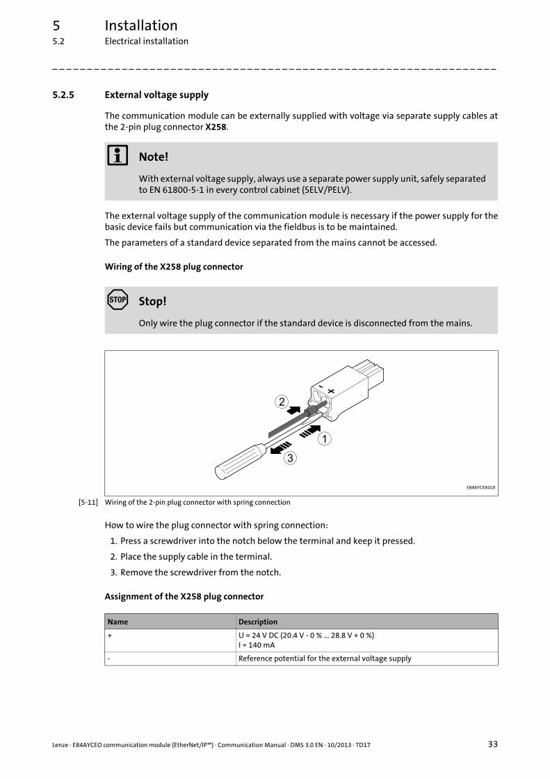
5.2.5 External voltage supply
The communication module can be externally supplied with voltage via separate supply cables atthe 2-pin plug connector X258.
The external voltage supply of the communication module is necessary if the power supply for thebasic device fails but communication via the fieldbus is to be maintained.
The parameters of a standard device separated from the mains cannot be accessed.
Wiring of the X258 plug connector
[5-11] Wiring of the 2-pin plug connector with spring connection
How to wire the plug connector with spring connection:
1. Press a screwdriver into the notch below the terminal and keep it pressed.
2. Place the supply cable in the terminal.
3. Remove the screwdriver from the notch.
Assignment of the X258 plug connector
Note!
With external voltage supply, always use a separate power supply unit, safely separated to EN 61800-5-1 in every control cabinet (SELV/PELV).
Stop!
Only wire the plug connector if the standard device is disconnected from the mains.
E84AYCXX010
Name Description
+ U = 24 V DC (20.4 V - 0 % ... 28.8 V + 0 %)I = 140 mA
- Reference potential for the external voltage supply

5 Installation5.2 Electrical installation
34 Lenze · E84AYCEO communication module (EtherNet/IP™) · Communication Manual · DMS 3.0 EN · 10/2013 · TD17
_ _ _ _ _ _ _ _ _ _ _ _ _ _ _ _ _ _ _ _ _ _ _ _ _ _ _ _ _ _ _ _ _ _ _ _ _ _ _ _ _ _ _ _ _ _ _ _ _ _ _ _ _ _ _ _ _ _ _ _ _ _ _ _
Terminal data
Range Values
Electrical connection 2-pin plug connector with spring connection
Possible connections Rigid:
0.2 ... 1.5 mm2 (AWG 24 ... 16)
Flexible:
Without wire end ferrule0.2 ... 1.5 mm2 (AWG 24 ... 16)
With wire end ferrule, without plastic sleeve0.2 ... 1.5 mm2 (AWG 24 ... 16)
With wire end ferrule, with plastic sleeve0.2 ... 1.5 mm2 (AWG 24 ... 16)
Stripping length 10 mm

Lenze · E84AYCEO communication module (EtherNet/IP™) · Communication Manual · DMS 3.0 EN · 10/2013 · TD17 35
6 Commissioning6.1 Before initial switch-on
_ _ _ _ _ _ _ _ _ _ _ _ _ _ _ _ _ _ _ _ _ _ _ _ _ _ _ _ _ _ _ _ _ _ _ _ _ _ _ _ _ _ _ _ _ _ _ _ _ _ _ _ _ _ _ _ _ _ _ _ _ _ _ _
6 Commissioning
During commissioning, plant-specific data such as motor parameters, operating parameters,responses, and parameters for fieldbus communication are defined for the inverter. Lenze devicesuse codes for this purpose.
The codes of the inverter and for communication are saved to the memory module in a non-volatiledata set.
In addition, there are codes for diagnosing and monitoring the stations.
Parameter reference ( 106)
6.1 Before initial switch-on
Stop!
Before you switch on the Inverter Drive 8400 with the communication module for the first time, check all the wiring for completeness, short-circuits and earth faults.

6 Commissioning6.2 Configuring the host system (scanner)
36 Lenze · E84AYCEO communication module (EtherNet/IP™) · Communication Manual · DMS 3.0 EN · 10/2013 · TD17
_ _ _ _ _ _ _ _ _ _ _ _ _ _ _ _ _ _ _ _ _ _ _ _ _ _ _ _ _ _ _ _ _ _ _ _ _ _ _ _ _ _ _ _ _ _ _ _ _ _ _ _ _ _ _ _ _ _ _ _ _ _ _ _
6.2 Configuring the host system (scanner)
To be able to communicate with the communication module, the host (scanner) must be configuredfirst.
The configuration of EtherNet/IP networks always requires an EtherNet/IP configuration software(e.g. »RSLogix 5000« from Rockwell) for the host system (scanner).
The configuration software is necessary for the programming of controller programs, EtherNet/IPconfiguration, real-time execution and diagnostics.
The basic parameters of the communication module are stored in the internal configurationmemory and can be used for node detection by the scanner.
For node detection (fieldbus scan), the corresponding device descriptions of the Lenze device familyare used.
Tip!
Here you will find information on configuring with the »RSLogix 5000« programmingsoftware from Rockwell:
I/O configuration with »RSLogix 5000« version 19 or lower ( 68)
I/O configuration with »RSLogix 5000« version 20 or higher ( 73)

Lenze · E84AYCEO communication module (EtherNet/IP™) · Communication Manual · DMS 3.0 EN · 10/2013 · TD17 37
6 Commissioning6.2 Configuring the host system (scanner)
_ _ _ _ _ _ _ _ _ _ _ _ _ _ _ _ _ _ _ _ _ _ _ _ _ _ _ _ _ _ _ _ _ _ _ _ _ _ _ _ _ _ _ _ _ _ _ _ _ _ _ _ _ _ _ _ _ _ _ _ _ _ _ _
6.2.1 EDS files
Depending on the EtherNet/IP scanner configuration software, the EDS files (Electronic Data Sheet)may be used for the configuration of the network profile, the communication with the participatingdevices and the automatic generation of tags. For this purpose, the EDS files have to be importedinto the controller project of the EtherNet/IP configuration software.
The EDS file required for the configuration can be found in the download area at:
www.Lenze.com
Tip!
From version 20 onwards, Rockwell's »RSLogix 5000« programming software features an"EDS Hardware Installation Tool" that can be used to ...• install/import EDS files;• create EDS files;• carry out EDS uploads;• delete EDS files from your controller project.
In »RSLogix 5000«, the dialog for the "EDS Hardware Installation Tool" is self-explanatoryand not described further in this documentation.

6 Commissioning6.2 Configuring the host system (scanner)
38 Lenze · E84AYCEO communication module (EtherNet/IP™) · Communication Manual · DMS 3.0 EN · 10/2013 · TD17
_ _ _ _ _ _ _ _ _ _ _ _ _ _ _ _ _ _ _ _ _ _ _ _ _ _ _ _ _ _ _ _ _ _ _ _ _ _ _ _ _ _ _ _ _ _ _ _ _ _ _ _ _ _ _ _ _ _ _ _ _ _ _ _
6.2.2 Example: IP configuration of the Allen-Bradley 1769-L32E CompactLogix controller
In this example, the Allen-Bradley CompactLogix control unit 1769-L32E with integrated EtherNet/IP interface is used for communication with the Inverter Drives 8400.
The »RSLogix 5000« programming software from Rockwell is used for the configuration.
To establish communication via an EtherNet/IP network, add the controller and its scanner to the I/O configuration.
How to set the IP configuration of the 1769-L32E CompactLogix controller using the »RSLogix 5000« programming software:
1. Click on the I/O Configuration folder in the configuration tree.
2. Right click on "1769-L32E Ethernet Port LocalENB" and select "Properties" from the context menu.
3. Go to the General tab of the "Module Properties: ..." dialog window and enter the IP address of the scanner.
4. Then click OK.

Lenze · E84AYCEO communication module (EtherNet/IP™) · Communication Manual · DMS 3.0 EN · 10/2013 · TD17 39
6 Commissioning6.2 Configuring the host system (scanner)
_ _ _ _ _ _ _ _ _ _ _ _ _ _ _ _ _ _ _ _ _ _ _ _ _ _ _ _ _ _ _ _ _ _ _ _ _ _ _ _ _ _ _ _ _ _ _ _ _ _ _ _ _ _ _ _ _ _ _ _ _ _ _ _
5. Go to the Port Configuration tab and enter the IP configuration, BOOTP setting, Ethernet baud rate and duplex mode.
6. Then click OK.• Now, the scanner is configured for the EtherNet/IP network.• Here you will find information on project planning with the »RSLogix 5000«
programming software from Rockwell:I/O configuration with »RSLogix 5000« version 19 or lower ( 68) I/O configuration with »RSLogix 5000« version 20 or higher ( 73)
6 Commissioning6.3 Setting node addresses by means of rotary coding switches
40 Lenze · E84AYCEO communication module (EtherNet/IP™) · Communication Manual · DMS 3.0 EN · 10/2013 · TD17
_ _ _ _ _ _ _ _ _ _ _ _ _ _ _ _ _ _ _ _ _ _ _ _ _ _ _ _ _ _ _ _ _ _ _ _ _ _ _ _ _ _ _ _ _ _ _ _ _ _ _ _ _ _ _ _ _ _ _ _ _ _ _ _
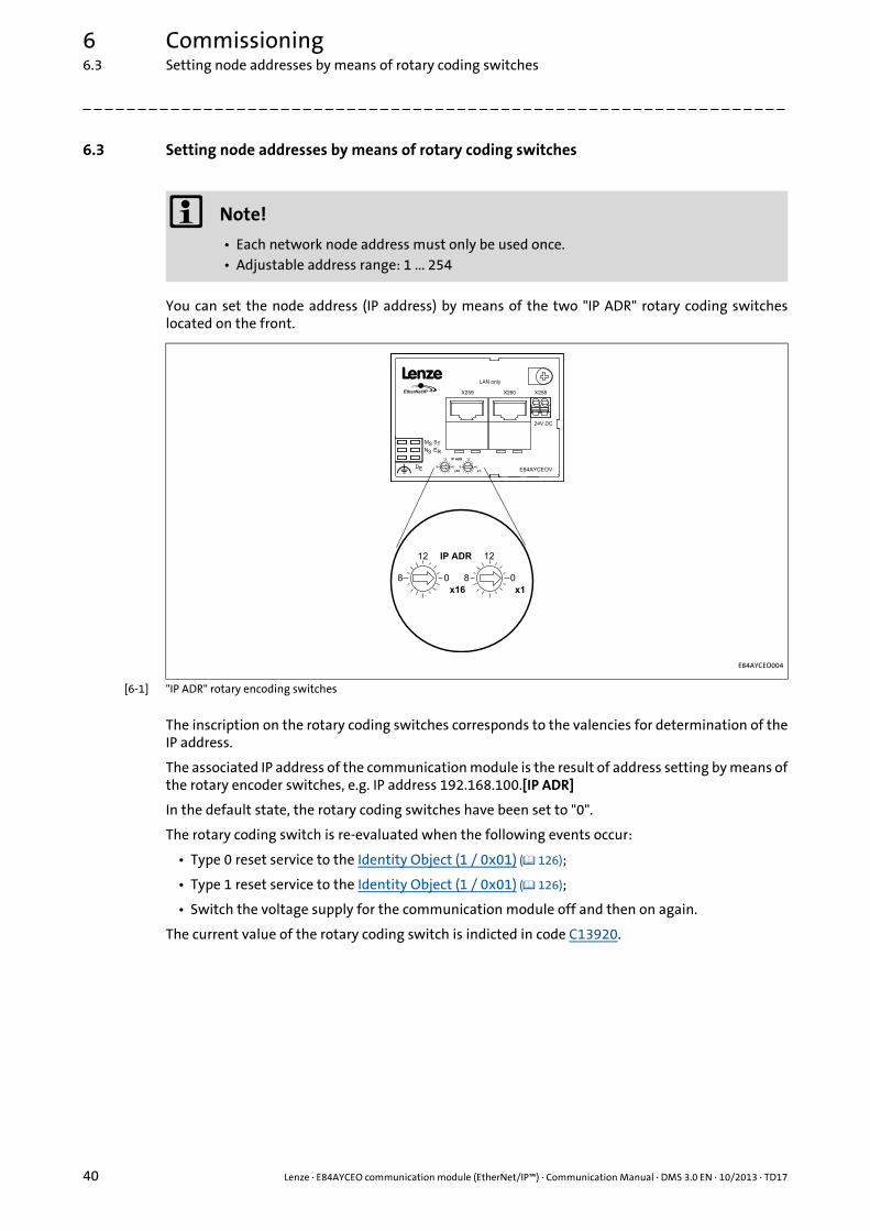
6.3 Setting node addresses by means of rotary coding switches
You can set the node address (IP address) by means of the two "IP ADR" rotary coding switcheslocated on the front.
[6-1] "IP ADR" rotary encoding switches
The inscription on the rotary coding switches corresponds to the valencies for determination of theIP address.
The associated IP address of the communication module is the result of address setting by means ofthe rotary encoder switches, e.g. IP address 192.168.100.[IP ADR]
In the default state, the rotary coding switches have been set to "0".
The rotary coding switch is re-evaluated when the following events occur:
• Type 0 reset service to the Identity Object (1 / 0x01) ( 126);
• Type 1 reset service to the Identity Object (1 / 0x01) ( 126);
• Switch the voltage supply for the communication module off and then on again.
The current value of the rotary coding switch is indicted in code C13920.
Note!
• Each network node address must only be used once.• Adjustable address range: 1 ... 254
E84AYCEO004

Lenze · E84AYCEO communication module (EtherNet/IP™) · Communication Manual · DMS 3.0 EN · 10/2013 · TD17 41
6 Commissioning6.3 Setting node addresses by means of rotary coding switches
_ _ _ _ _ _ _ _ _ _ _ _ _ _ _ _ _ _ _ _ _ _ _ _ _ _ _ _ _ _ _ _ _ _ _ _ _ _ _ _ _ _ _ _ _ _ _ _ _ _ _ _ _ _ _ _ _ _ _ _ _ _ _ _
Possible settings of the rotary coding switches
Example: Setting of the node address ’52’
Position of the rotary coding switches Description
0 × 16 0 × 1Default status:
• Value from code C13005 (IP configuration reference, 1: BOOTP)• The setting can also be made by means of write-access to
attribute 3 (Configuration Control) of instance 1 of the TCP/IP Interface Object (245 / 0xF5) ( 141).
0 ... 15 1 ... 14IP address 1 ... 254
• The static address stored in subcode C13000/1...3 is used.• The subcode C13000/4 is replaced with the value of the rotary
coding switch.
15 15This setting resets the codes for IP configuration:
• C13000 (IP address)• C13001 (subnet mask)• C13002 (gateway address)• C13005 (IP configuration reference)• C13006 (Multicast IP start address)• C13017 (Ethernet setting: Autonegotiation)• C13018 (Multicast setting: Default algorithm)• C13021 (Quality of Service (VLAN tagging): deactivated)• C13846 (Address conflict detection (ACD): activated)
Position of the rotary coding switches Resulting node address
3 × 16 4 × 1 (3 × 16) + (4 × 1) = 52

6 Commissioning6.4 Setting the IP configuration of the Inverter Drive 8400
42 Lenze · E84AYCEO communication module (EtherNet/IP™) · Communication Manual · DMS 3.0 EN · 10/2013 · TD17
_ _ _ _ _ _ _ _ _ _ _ _ _ _ _ _ _ _ _ _ _ _ _ _ _ _ _ _ _ _ _ _ _ _ _ _ _ _ _ _ _ _ _ _ _ _ _ _ _ _ _ _ _ _ _ _ _ _ _ _ _ _ _ _
6.4 Setting the IP configuration of the Inverter Drive 8400
IP configuration is necessary in order to assign an address to the Inverter Drive 8400 so thatcommunication between the PC/»Engineer« or the scanner and the drive is possible via EtherNet/IP. For this purpose, an IP address, subnet mask and gateway address have to be assigned. You canassign these IP parameters for the Inverter Drive 8400 in the following ways:
• Setting via the EtherNet/IP configurator of the »Engineer« ( 43)
• Setting via codes in the »Engineer« ( 45)
• Setting via a BOOTP/DHCP server ( 47)
• Setting via the TCP/IP Interface Object (0xF5) ( 47)
Note!
• The assignment of invalid combinations of IP address, subnet mask, and gateway address can have the consequence that no connection to the EtherNet/IP network can be established.
• Codes C13010 (IP address), C13011 (subnet mask), C13012 (gateway address), and C13016 (multicast IP address) show the IP parameters currently used.
• In the case of impermissible settings, the error message EtherNet/IP: Invalid IP parameters [0x01bc6533] ( 99) is output.

Lenze · E84AYCEO communication module (EtherNet/IP™) · Communication Manual · DMS 3.0 EN · 10/2013 · TD17 43
6 Commissioning6.4 Setting the IP configuration of the Inverter Drive 8400
_ _ _ _ _ _ _ _ _ _ _ _ _ _ _ _ _ _ _ _ _ _ _ _ _ _ _ _ _ _ _ _ _ _ _ _ _ _ _ _ _ _ _ _ _ _ _ _ _ _ _ _ _ _ _ _ _ _ _ _ _ _ _ _
6.4.1 Setting via the EtherNet/IP configurator of the »Engineer«
How to set the IP parameters via the EtherNet/IP configurator:
1. Execute the menu command Online PROFINET /EtherNet/IP configurator addresses ....
The "Assign IP addresses" dialog window is opened and all Lenze EtherNet/IP nodes connected are listed.
Note!
• Changes in the IP parameters will become effective immediately.• An already existing IP connection to the Inverter Drive 8400 is interrupted.
6 Commissioning6.4 Setting the IP configuration of the Inverter Drive 8400
44 Lenze · E84AYCEO communication module (EtherNet/IP™) · Communication Manual · DMS 3.0 EN · 10/2013 · TD17
_ _ _ _ _ _ _ _ _ _ _ _ _ _ _ _ _ _ _ _ _ _ _ _ _ _ _ _ _ _ _ _ _ _ _ _ _ _ _ _ _ _ _ _ _ _ _ _ _ _ _ _ _ _ _ _ _ _ _ _ _ _ _ _
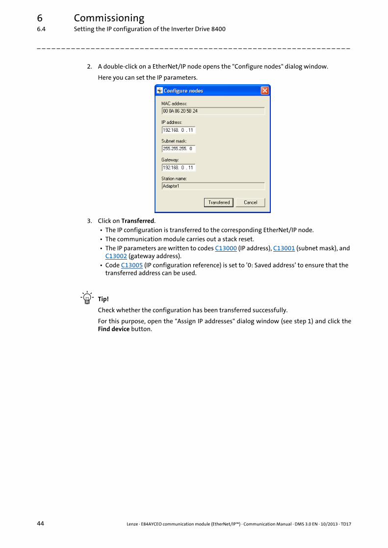
2. A double-click on a EtherNet/IP node opens the "Configure nodes" dialog window.
Here you can set the IP parameters.
3. Click on Transferred.• The IP configuration is transferred to the corresponding EtherNet/IP node.• The communication module carries out a stack reset.• The IP parameters are written to codes C13000 (IP address), C13001 (subnet mask), and
C13002 (gateway address).• Code C13005 (IP configuration reference) is set to ’0: Saved address’ to ensure that the
transferred address can be used.
Tip!
Check whether the configuration has been transferred successfully.
For this purpose, open the "Assign IP addresses" dialog window (see step 1) and click theFind device button.

Lenze · E84AYCEO communication module (EtherNet/IP™) · Communication Manual · DMS 3.0 EN · 10/2013 · TD17 45
6 Commissioning6.4 Setting the IP configuration of the Inverter Drive 8400
_ _ _ _ _ _ _ _ _ _ _ _ _ _ _ _ _ _ _ _ _ _ _ _ _ _ _ _ _ _ _ _ _ _ _ _ _ _ _ _ _ _ _ _ _ _ _ _ _ _ _ _ _ _ _ _ _ _ _ _ _ _ _ _
6.4.2 Setting via codes in the »Engineer«
You can also set the IP parameters manually in the »Engineer« under the Settings tab. The valueswill be transferred to the corresponding codes.
How to activate changed settings in the »Engineer«:
1. Execute device command C00002 = "11: Save all parameter sets".
The current IP configuration is stored in the memory module of the drive.
2. Carry out a "Type 0 reset" for the Identity Object (1 / 0x01) ( 126) of the node, or switch the voltage supply of the communication module off and on again.
Settings / Display Description
Rotary coding switch Display of the value set by means of the rotary coding switches (C13920).Setting node addresses by means of rotary coding switches ( 40)
IP Config Control Selection (C13005) of how the IP configuration is to be made:• 0: The IP configuration currently stored in the communication module is
used.• 1: The IP configuration is assigned by a BOOTP server using the BOOTP.• 2: The IP configuration is assigned by a DHCP server using the DHCP.
IP Address Setting of the IP address (C13000)
Subnet mask Setting of the subnet mask (C13001)
Gateway Address Setting of the gateway address (C13002)
Multicast IP Start Address Setting of the Multicast IP start address (C13006)Setting the multicast configuration ( 48)
Multicast Config TTL Value Setting of the multicast TTL value (C13019)

6 Commissioning6.4 Setting the IP configuration of the Inverter Drive 8400
46 Lenze · E84AYCEO communication module (EtherNet/IP™) · Communication Manual · DMS 3.0 EN · 10/2013 · TD17
_ _ _ _ _ _ _ _ _ _ _ _ _ _ _ _ _ _ _ _ _ _ _ _ _ _ _ _ _ _ _ _ _ _ _ _ _ _ _ _ _ _ _ _ _ _ _ _ _ _ _ _ _ _ _ _ _ _ _ _ _ _ _ _
IP address
The IP address is set/changed in C13000.
The IP address currently used is displayed in C13010/1...4.
Subnet mask
The subnet mask indicates which part of the IP address is evaluated as net ID or host ID.
Valid subnet masks are defined in accordance with RFC 1878
The subnet mask is set/changed in C13001.
The subnet mask currently used is displayed in C13011/1...4.
Gateway address
The gateway address is valid if the network address of the IP address and the gateway address areidentical.
If the gateway address and the IP address are identical or if the address is ’0.0.0.0’, gatewayfunctionality is not used.
The gateway address is set/changed in C13002.
The gateway address currently used is displayed in C13012/1...4.
Example: Display of the IP address 192.168.124.16
Code C13010/1 C13010/2 C13010/3 C13010/4
Value 192 168 124 16
Example: Display of the subnet mask 255.255.255.0
Code C13011/1 C13011/2 C13011/3 C13011/4
Value 255 255 255 0
Example: Display of the gateway address 192.168.124.16
Code C13012/1 C13012/2 C13012/3 C13012/4
Value 192 168 124 16
Lenze · E84AYCEO communication module (EtherNet/IP™) · Communication Manual · DMS 3.0 EN · 10/2013 · TD17 47
6 Commissioning6.4 Setting the IP configuration of the Inverter Drive 8400
_ _ _ _ _ _ _ _ _ _ _ _ _ _ _ _ _ _ _ _ _ _ _ _ _ _ _ _ _ _ _ _ _ _ _ _ _ _ _ _ _ _ _ _ _ _ _ _ _ _ _ _ _ _ _ _ _ _ _ _ _ _ _ _
6.4.3 Setting via a BOOTP/DHCP server
DHCP is the acronym for "Dynamic Host Configuration Protocol". This protocol is defined inRFC 2131 and is a compatible advancement of the "Bootstrap Protocol" (BOOTP) according toRFC 951.
Both protocols enable network nodes to query information about the network configuration (e.g.the IP address) from a server via a TCP/IP network. The BOOTP/DHCP server assigns the IP addressto the client dynamically from a defined address range. This means that the client receives anunambiguous IP address.
Code C13005 is used to select how the IP configuration is to be made:
• Value ’0’: The IP configuration currently saved in the communication module is used.
• Value ’1’: BOOTP is used. (Lenze standard setting)
• Value ’2’: DHCP is used.
The setting can also be selected by write access to attribute 3 (configuration control) of instance 1of the TCP/IP Interface Object (245 / 0xF5) ( 141).
6.4.4 Setting via the TCP/IP Interface Object (0xF5)
With a scanner, the IP configuration can be set via attribute 5 (interface configuration) of instance 1of the TCP/IP Interface Object (245 / 0xF5) ( 141).
After the IP configuration, carry out a node reset ("power off/on" or "Type 0 reset" for the IdentityObject (1 / 0x01) ( 126)).
In the »Engineer«, codes C13010 (IP address), C13011 (subnet mask), C13012 (gateway address),and C13016 (multicast IP address) show the IP parameters currently used.
6 Commissioning6.4 Setting the IP configuration of the Inverter Drive 8400
48 Lenze · E84AYCEO communication module (EtherNet/IP™) · Communication Manual · DMS 3.0 EN · 10/2013 · TD17
_ _ _ _ _ _ _ _ _ _ _ _ _ _ _ _ _ _ _ _ _ _ _ _ _ _ _ _ _ _ _ _ _ _ _ _ _ _ _ _ _ _ _ _ _ _ _ _ _ _ _ _ _ _ _ _ _ _ _ _ _ _ _ _
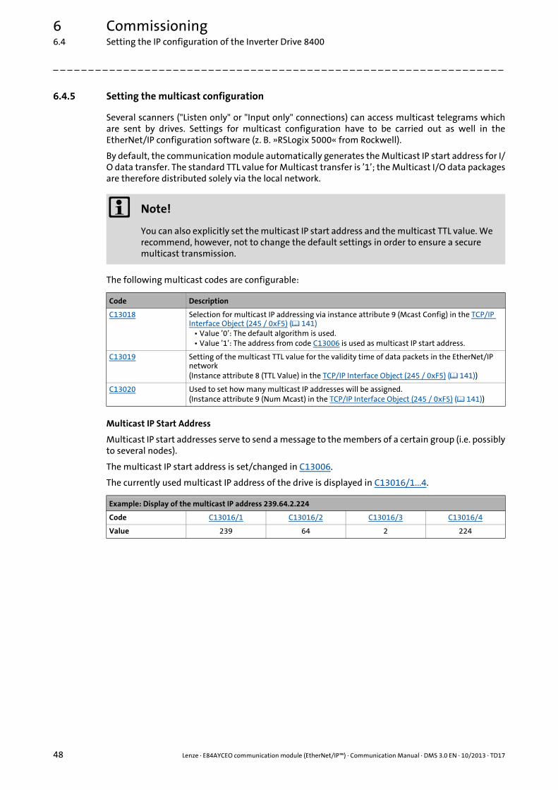
6.4.5 Setting the multicast configuration
Several scanners ("Listen only" or "Input only" connections) can access multicast telegrams whichare sent by drives. Settings for multicast configuration have to be carried out as well in theEtherNet/IP configuration software (z. B. »RSLogix 5000« from Rockwell).
By default, the communication module automatically generates the Multicast IP start address for I/O data transfer. The standard TTL value for Multicast transfer is ’1’; the Multicast I/O data packagesare therefore distributed solely via the local network.
The following multicast codes are configurable:
Multicast IP Start Address
Multicast IP start addresses serve to send a message to the members of a certain group (i.e. possiblyto several nodes).
The multicast IP start address is set/changed in C13006.
The currently used multicast IP address of the drive is displayed in C13016/1...4.
Note!
You can also explicitly set the multicast IP start address and the multicast TTL value. We recommend, however, not to change the default settings in order to ensure a secure multicast transmission.
Code Description
C13018 Selection for multicast IP addressing via instance attribute 9 (Mcast Config) in the TCP/IP Interface Object (245 / 0xF5) ( 141)
• Value ’0’: The default algorithm is used.• Value ’1’: The address from code C13006 is used as multicast IP start address.
C13019 Setting of the multicast TTL value for the validity time of data packets in the EtherNet/IP network(Instance attribute 8 (TTL Value) in the TCP/IP Interface Object (245 / 0xF5) ( 141))
C13020 Used to set how many multicast IP addresses will be assigned.(Instance attribute 9 (Num Mcast) in the TCP/IP Interface Object (245 / 0xF5) ( 141))
Example: Display of the multicast IP address 239.64.2.224
Code C13016/1 C13016/2 C13016/3 C13016/4
Value 239 64 2 224

Lenze · E84AYCEO communication module (EtherNet/IP™) · Communication Manual · DMS 3.0 EN · 10/2013 · TD17 49
6 Commissioning6.5 Establishing an online connection via EtherNet/IP with the Lenze »Engineer«
_ _ _ _ _ _ _ _ _ _ _ _ _ _ _ _ _ _ _ _ _ _ _ _ _ _ _ _ _ _ _ _ _ _ _ _ _ _ _ _ _ _ _ _ _ _ _ _ _ _ _ _ _ _ _ _ _ _ _ _ _ _ _ _
6.5 Establishing an online connection via EtherNet/IP with the Lenze »Engineer«
[6-2] Example set-up with an Allen Bradley CompactLogix Controller 1769-L32E (scanner)
For an online connection between the »Engineer« and the drive, the drive must have an IP address(see Setting the IP configuration of the Inverter Drive 8400 ( 42)).
Note!
• In order to ensure perfect operation of cyclic EtherNet/IP communication, online access with the »Engineer« should be executed via an IEEE 802.1Q-capable switch.
• The IEEE 802.1Q-capable switch integrated in the communication module can manage cyclical EtherNet/IP-communication primarily for normal TCP/IP communication. In the case of EtherNet/IP, this is done by means of the VLAN identification in the Ethernet frame (can be set in C13021).
• If the redundancy protocol DLR (Device Level Ring) is used, the switch also must be DLR-compliant.

6 Commissioning6.5 Establishing an online connection via EtherNet/IP with the Lenze »Engineer«
50 Lenze · E84AYCEO communication module (EtherNet/IP™) · Communication Manual · DMS 3.0 EN · 10/2013 · TD17
_ _ _ _ _ _ _ _ _ _ _ _ _ _ _ _ _ _ _ _ _ _ _ _ _ _ _ _ _ _ _ _ _ _ _ _ _ _ _ _ _ _ _ _ _ _ _ _ _ _ _ _ _ _ _ _ _ _ _ _ _ _ _ _
In the »Engineer«, you can use the Online Set communication path and go online menu commandto select the EtherNet/IP communication path. The previously configured EtherNet/IP nodes areshown in the "Communication path" dialog window:
If the device access path is not configured correctly, the IP address of the drive selected in thedisplay field can be entered manually here.
Via the Search/Enter button, you can establish a connection to devices which have notappeared in the display field. Corresponding settings for this can be made in the "Enter IP Address"dialog window that will appear:
Here you can enter an IP address manually or execute the following actions using the buttons:
• Execute the console command Ping.
• Assign the IP address via the Configurator.
Setting via the EtherNet/IP configurator of the »Engineer« ( 43)
• Select the device access path to the desired drive by clicking Find.
After having established the online connection, you can continue work with the »Engineer« asusual.

Lenze · E84AYCEO communication module (EtherNet/IP™) · Communication Manual · DMS 3.0 EN · 10/2013 · TD17 51
6 Commissioning6.6 Initial switch-on
_ _ _ _ _ _ _ _ _ _ _ _ _ _ _ _ _ _ _ _ _ _ _ _ _ _ _ _ _ _ _ _ _ _ _ _ _ _ _ _ _ _ _ _ _ _ _ _ _ _ _ _ _ _ _ _ _ _ _ _ _ _ _ _
6.6 Initial switch-on
Documentation for the Inverter Drive 8400
Observe the safety instructions and information on residual hazards.
Note!
Establishing communication
In order to establish communication via an externally supplied communication module, the standard device must be switched on as well.
For further communication of the externally supplied module it is not relevant whether the standard device is switched on or not.
Activating changed setting
In order to activate any changed settings, ...• execute the device command "11: Save all parameter sets" via the standard device
code C00002 and ...• Carry out a "Type 0 reset" for the Identity Object (1 / 0x01) ( 126) of the node, or
switch the voltage supply of the communication module off and on again.
Protection against uncontrolled restart
After a fault (e.g. short-term mains failure), it is sometimes undesirable or even impermissible for the drive to restart.
The restart protection is activated in the Lenze setting of the Inverter Drives 8400.
You can set the restart behaviour of the drive via C00142 ("Autostart Option"):
C00142 = 9 (Lenze setting)• The inverter remains inhibited (even if the fault is no longer active).• Bit 0 (inhibit at "power-on") and bit 3 (inhibit in the case of undervoltage) are set.• An explicit inverter enable causes the drive to start up in a controlled manner: LOW-
HIGH edge at digital input X4/RFR.
C00142 = 8 (enabled)• In order to directly enable the device at switch-on, bit 0 must be set to zero (FALSE).• An uncontrolled restart of the drive is possible.

7 Data transfer
52 Lenze · E84AYCEO communication module (EtherNet/IP™) · Communication Manual · DMS 3.0 EN · 10/2013 · TD17
_ _ _ _ _ _ _ _ _ _ _ _ _ _ _ _ _ _ _ _ _ _ _ _ _ _ _ _ _ _ _ _ _ _ _ _ _ _ _ _ _ _ _ _ _ _ _ _ _ _ _ _ _ _ _ _ _ _ _ _ _ _ _ _
7 Data transfer
EtherNet/IP uses CIP™ (Common Industrial Protocol) for the data exchange between devices via anEthernet network – just like the closely related bus systems DeviceNet and ControlNet.
Lenze implements the CIP following the ODVA standard (Open DeviceNet Vendor Association,www.odva.org) and supports the two main types of EtherNet/IP communication:
• Explicit messaging (for parameter data)
• Implicit messaging (for I/O data)

Lenze · E84AYCEO communication module (EtherNet/IP™) · Communication Manual · DMS 3.0 EN · 10/2013 · TD17 53
7 Data transfer7.1 Communication channels
_ _ _ _ _ _ _ _ _ _ _ _ _ _ _ _ _ _ _ _ _ _ _ _ _ _ _ _ _ _ _ _ _ _ _ _ _ _ _ _ _ _ _ _ _ _ _ _ _ _ _ _ _ _ _ _ _ _ _ _ _ _ _ _
7.1 Communication channels
EtherNet/IP transmits parameter data and I/O data between the host system (scanner) and thedrives (adapters) connected to the fieldbus. The data are transmitted via correspondingcommunication channels depending on their time-critical behaviour.
The I/O data channel transmits I/O data by means of "implicit messages".
• The inverter is controlled by means of the I/O data.
• The transmission of I/O data is time-critical.
• I/O data are transmitted cyclically between the host system (scanner) and the drives (adapters) (permanent exchange of current input and output data).
• The host system (scanner) has direct access to the I/O data (the data are, for example, stored directly in the I/O area).
• In the case of Inverter Drives 8400, a maximum of 16 data words (max. 32 bytes) can be exchanged per direction.
• I/O data are not stored in the inverter.
• I/O data are e.g. setpoints, actual values, control and status words
The parameter data channel transmits parameter data by means of "explicit messages".
• The transmission of parameter data is usually not time-critical.
• Examples of parameter data are operating parameters, motor data, and diagnostic information.
• The parameter data channel provides access to all Lenze codes.
• Parameter changes must be saved by means of code C00002 of the Inverter Drive 8400.
Note!
The terms "input" and "output" refer to the point of view of the scanner:• Input data is produced by the adapter and consumed by the scanner.• Output data is produced by the scanner and consumed by the adapter.

7 Data transfer7.2 Telegram types
54 Lenze · E84AYCEO communication module (EtherNet/IP™) · Communication Manual · DMS 3.0 EN · 10/2013 · TD17
_ _ _ _ _ _ _ _ _ _ _ _ _ _ _ _ _ _ _ _ _ _ _ _ _ _ _ _ _ _ _ _ _ _ _ _ _ _ _ _ _ _ _ _ _ _ _ _ _ _ _ _ _ _ _ _ _ _ _ _ _ _ _ _
7.2 Telegram types
The "implicit message" and "explicit message" telegram types are transmitted between the hostsystem (scanner) and the drive (adapter).
Implicit messages (I/O data transfer)
"Implicit messages" are transmitted or received according to the producer/consumer principle.There is one transmitter and no receiver or an optional number of receivers.
The "cyclic I/O data" transmission mode is supported. The scanner and the adapter use "cyclic I/Odata" to generate their data independently of each other, which are then transmitted depending ona timer. The user must set the value of the timer in the scanner.
Explicit messages (parameter data transfer)
"Explicit messages" serve to configure and parameterise the individual EtherNet/IP nodes.
Two nodes have a client/server relationship: The client transmits a job (request). The server receives this job and tries to accomplish it. The serverthen transmits the requested data (positive response) or an error message (negative response).

Lenze · E84AYCEO communication module (EtherNet/IP™) · Communication Manual · DMS 3.0 EN · 10/2013 · TD17 55
7 Data transfer7.3 EtherNet/IP state diagram
_ _ _ _ _ _ _ _ _ _ _ _ _ _ _ _ _ _ _ _ _ _ _ _ _ _ _ _ _ _ _ _ _ _ _ _ _ _ _ _ _ _ _ _ _ _ _ _ _ _ _ _ _ _ _ _ _ _ _ _ _ _ _ _
7.3 EtherNet/IP state diagram
[7-1] EtherNet/IP state diagram
The current EtherNet/IP device state is ...
• output via code C13861;
• output in the Identity Object (1 / 0x01) ( 126) via instance attributes 5 and 8;
• indicated via the MS LED (see LED status displays ( 89)).
8 I/O data transfer (implicit messages)
56 Lenze · E84AYCEO communication module (EtherNet/IP™) · Communication Manual · DMS 3.0 EN · 10/2013 · TD17
_ _ _ _ _ _ _ _ _ _ _ _ _ _ _ _ _ _ _ _ _ _ _ _ _ _ _ _ _ _ _ _ _ _ _ _ _ _ _ _ _ _ _ _ _ _ _ _ _ _ _ _ _ _ _ _ _ _ _ _ _ _ _ _
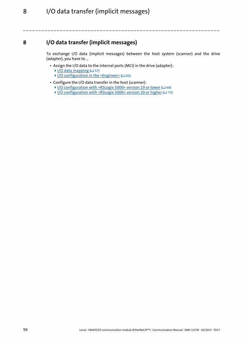
8 I/O data transfer (implicit messages)
To exchange I/O data (implicit messages) between the host system (scanner) and the drive(adapter), you have to ...
• Assign the I/O data to the internal ports (MCI) in the drive (adapter):I/O data mapping ( 57) I/O configuration in the »Engineer« ( 62)
• Configure the I/O data transfer in the host (scanner):I/O configuration with »RSLogix 5000« version 19 or lower ( 68) I/O configuration with »RSLogix 5000« version 20 or higher ( 73)
Lenze · E84AYCEO communication module (EtherNet/IP™) · Communication Manual · DMS 3.0 EN · 10/2013 · TD17 57
8 I/O data transfer (implicit messages)8.1 I/O data mapping
_ _ _ _ _ _ _ _ _ _ _ _ _ _ _ _ _ _ _ _ _ _ _ _ _ _ _ _ _ _ _ _ _ _ _ _ _ _ _ _ _ _ _ _ _ _ _ _ _ _ _ _ _ _ _ _ _ _ _ _ _ _ _ _
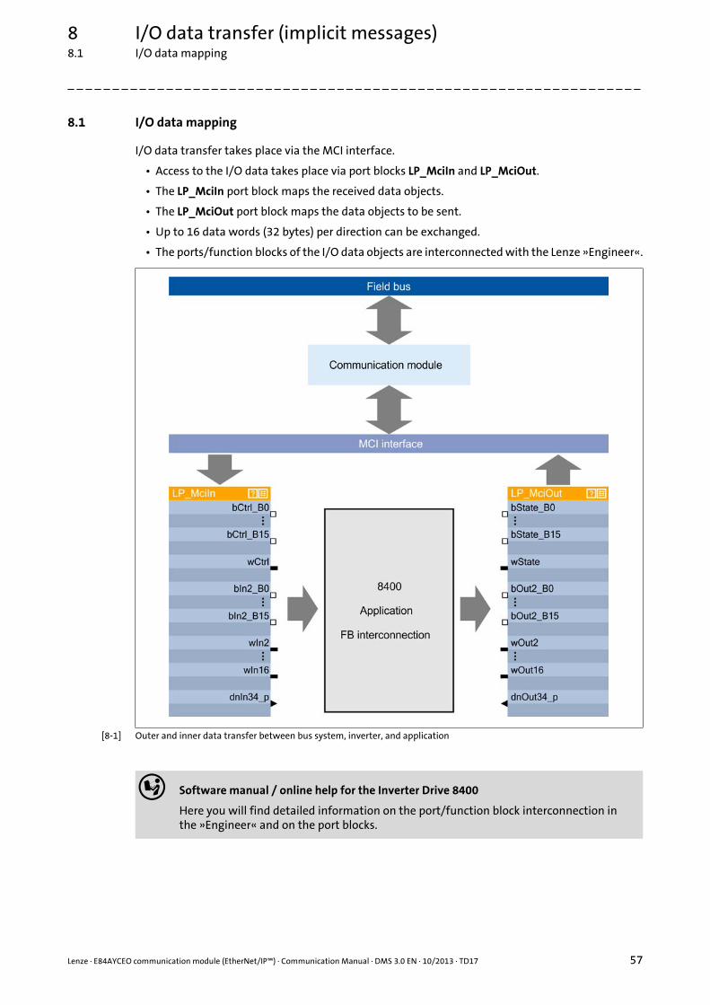
8.1 I/O data mapping
I/O data transfer takes place via the MCI interface.
• Access to the I/O data takes place via port blocks LP_MciIn and LP_MciOut.
• The LP_MciIn port block maps the received data objects.
• The LP_MciOut port block maps the data objects to be sent.
• Up to 16 data words (32 bytes) per direction can be exchanged.
• The ports/function blocks of the I/O data objects are interconnected with the Lenze »Engineer«.
[8-1] Outer and inner data transfer between bus system, inverter, and application
Software manual / online help for the Inverter Drive 8400
Here you will find detailed information on the port/function block interconnection in the »Engineer« and on the port blocks.

8 I/O data transfer (implicit messages)8.2 Technology applications (TA) / drive profiles
58 Lenze · E84AYCEO communication module (EtherNet/IP™) · Communication Manual · DMS 3.0 EN · 10/2013 · TD17
_ _ _ _ _ _ _ _ _ _ _ _ _ _ _ _ _ _ _ _ _ _ _ _ _ _ _ _ _ _ _ _ _ _ _ _ _ _ _ _ _ _ _ _ _ _ _ _ _ _ _ _ _ _ _ _ _ _ _ _ _ _ _ _
8.2 Technology applications (TA) / drive profiles
The Inverter Drives 8400 is provided with various drive profiles. They define a standardised/individual control and status word assignment and the standardisation of setpoints and actualvalue scalings.
The following drive profiles are supported by the Inverter Drives 8400:
• Lenze technology applications / user-definable parameter sets
• "AC Drive Profile" application
8.2.1 Lenze technology applications / user-definable parameter sets
The technology applications integrated in the drive provide the main signal flow for realising ageneral or specific drive solution.
For using the Lenze technology application selection in the »Engineer« via standard device codeC00005, the following assembly object instances have to be used in the host (scanner):
See also Assembly Object (4 / 0x04) ( 129).
The custom assemblies also allow for a user-definable parameter setting, depending on theapplication. 16 data words can be freely assigned with variables of the MCI port blocks in the»Engineer«.
The user-definable parameter setting can be used in addition to the previously set technologyapplication.
Lenze technology application / configuring user-definable parameter sets ( 62)
Tip!
Here you will find information on configuring with the »RSLogix 5000« programmingsoftware from Rockwell:
I/O configuration with »RSLogix 5000« version 19 or lower ( 68)
I/O configuration with »RSLogix 5000« version 20 or higher ( 73)
Instance ID Assembly object instance
[dec] [hex]
110 0x6E Custom Output(from the adapter to the scanner)
111 0x6F Custom Input(from the adapter to the scanner)

Lenze · E84AYCEO communication module (EtherNet/IP™) · Communication Manual · DMS 3.0 EN · 10/2013 · TD17 59
8 I/O data transfer (implicit messages)8.2 Technology applications (TA) / drive profiles
_ _ _ _ _ _ _ _ _ _ _ _ _ _ _ _ _ _ _ _ _ _ _ _ _ _ _ _ _ _ _ _ _ _ _ _ _ _ _ _ _ _ _ _ _ _ _ _ _ _ _ _ _ _ _ _ _ _ _ _ _ _ _ _
8.2.2 "AC Drive Profile" application
From inverter drive version V13.00 and communication module version V01.02, the EtherNet/IP-specific "AC Drive Profile" is supported.
The standard device code C00005 = "1100: AC Drive Profile" serves to select the "AC Drive Profile"application.
The "AC Drive Profile" contains ...
• the data basis for motor parameters,
• management functions of the motor control devices,
• Device-specific functions of the drive, e.g. speed ramps, torque control etc.
For using the "AC Drive Profile", the following assembly object instances in the host (scanner) haveto be used:
See also:
• Assembly Object (4 / 0x04) ( 129)
• "AC Drive Profile" objects ( 148)
Tip!
Here you will find information on configuring with the »RSLogix 5000« programmingsoftware from Rockwell:
I/O configuration with »RSLogix 5000« version 19 or lower ( 68)
I/O configuration with »RSLogix 5000« version 20 or higher ( 73)
Instance ID Assembly object instance
[dec] [hex]
20 0x14 Basic Speed Control Output Outputs: From the scanner to the adapter
21 0x15 Extended Speed Control Output
22 0x16 Speed and Torque Control Output
23 0x17 Extended Speed and Torque Control Output
70 0x46 Basic Speed Control Input Inputs: From the adapter to the scanner
71 0x47 Extended Speed Control Input
72 0x48 Speed and Torque Control Input
73 0x49 Extended Speed and Torque Control Input
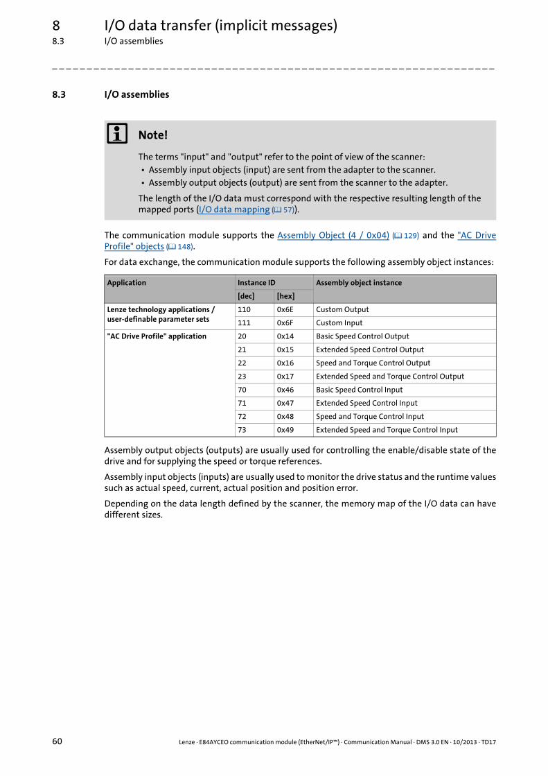
8 I/O data transfer (implicit messages)8.3 I/O assemblies
60 Lenze · E84AYCEO communication module (EtherNet/IP™) · Communication Manual · DMS 3.0 EN · 10/2013 · TD17
_ _ _ _ _ _ _ _ _ _ _ _ _ _ _ _ _ _ _ _ _ _ _ _ _ _ _ _ _ _ _ _ _ _ _ _ _ _ _ _ _ _ _ _ _ _ _ _ _ _ _ _ _ _ _ _ _ _ _ _ _ _ _ _
8.3 I/O assemblies
The communication module supports the Assembly Object (4 / 0x04) ( 129) and the "AC DriveProfile" objects ( 148).
For data exchange, the communication module supports the following assembly object instances:
Assembly output objects (outputs) are usually used for controlling the enable/disable state of thedrive and for supplying the speed or torque references.
Assembly input objects (inputs) are usually used to monitor the drive status and the runtime valuessuch as actual speed, current, actual position and position error.
Depending on the data length defined by the scanner, the memory map of the I/O data can havedifferent sizes.
Note!
The terms "input" and "output" refer to the point of view of the scanner:• Assembly input objects (input) are sent from the adapter to the scanner.• Assembly output objects (output) are sent from the scanner to the adapter.
The length of the I/O data must correspond with the respective resulting length of the mapped ports (I/O data mapping ( 57)).
Application Instance ID Assembly object instance
[dec] [hex]
Lenze technology applications /user-definable parameter sets
110 0x6E Custom Output
111 0x6F Custom Input
"AC Drive Profile" application 20 0x14 Basic Speed Control Output
21 0x15 Extended Speed Control Output
22 0x16 Speed and Torque Control Output
23 0x17 Extended Speed and Torque Control Output
70 0x46 Basic Speed Control Input
71 0x47 Extended Speed Control Input
72 0x48 Speed and Torque Control Input
73 0x49 Extended Speed and Torque Control Input

Lenze · E84AYCEO communication module (EtherNet/IP™) · Communication Manual · DMS 3.0 EN · 10/2013 · TD17 61
8 I/O data transfer (implicit messages)8.3 I/O assemblies
_ _ _ _ _ _ _ _ _ _ _ _ _ _ _ _ _ _ _ _ _ _ _ _ _ _ _ _ _ _ _ _ _ _ _ _ _ _ _ _ _ _ _ _ _ _ _ _ _ _ _ _ _ _ _ _ _ _ _ _ _ _ _ _
Assembly output objects (scanner Adapter)
Assembly output objects are assumed to have a 4-byte header (32-bit "run/idle header"). Whenmapping the assemblies, this header will automatically be added to the data stream by most Allen-Bradley PLC/SLC equipment.
If your PLC does not support this header (like the Rockwell PLCs do), add a preceding 32-bit headerto the output image.
You can then define the bit 0 of this header in the process image of your PLC:
• 0: Idle mode
• 1: Run mode
For the operation with Rockwell PLCs, adaptations are not required.
Assembly input objects (adapter scanner)
The assembly input objects are mapped in the adapter memory starting with byte 0.
The input objects are transmitted in a "modeless" manner, i.e. a 4-byte header (32-bit "Run/Idleheader") is not included in the transfer.
So the start address in the assembly memory map is the actual start of the first assembly dataelement.
Please observe the actual assembly lengths when mapping the input objects to the controllermemory.
The contents of the input data depends on the I/O data arrangement in the drive (I/O data mapping( 57)).
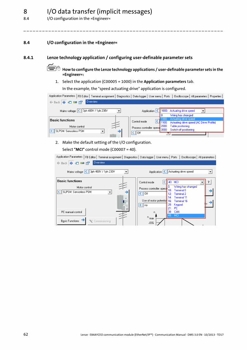
8 I/O data transfer (implicit messages)8.4 I/O configuration in the »Engineer«
62 Lenze · E84AYCEO communication module (EtherNet/IP™) · Communication Manual · DMS 3.0 EN · 10/2013 · TD17
_ _ _ _ _ _ _ _ _ _ _ _ _ _ _ _ _ _ _ _ _ _ _ _ _ _ _ _ _ _ _ _ _ _ _ _ _ _ _ _ _ _ _ _ _ _ _ _ _ _ _ _ _ _ _ _ _ _ _ _ _ _ _ _
8.4 I/O configuration in the »Engineer«
8.4.1 Lenze technology application / configuring user-definable parameter sets
How to configure the Lenze technology applications / user-definable parameter sets in the »Engineer«:
1. Select the application (C00005 = 1000) in the Application parameters tab.
In the example, the "speed actuating drive" application is configured.
2. Make the default setting of the I/O configuration.
Select "MCI" control mode (C00007 = 40).

Lenze · E84AYCEO communication module (EtherNet/IP™) · Communication Manual · DMS 3.0 EN · 10/2013 · TD17 63
8 I/O data transfer (implicit messages)8.4 I/O configuration in the »Engineer«
_ _ _ _ _ _ _ _ _ _ _ _ _ _ _ _ _ _ _ _ _ _ _ _ _ _ _ _ _ _ _ _ _ _ _ _ _ _ _ _ _ _ _ _ _ _ _ _ _ _ _ _ _ _ _ _ _ _ _ _ _ _ _ _
3. On the Ports tab, the port blocks MCI_IN and MCI_OUT for the I/O data objects are shown.
• By clicking the required port, the preconfigured signal combination can be obtained
from the application variables.
• If you want to complement or change the signal combination, click the Change Variable … button.

8 I/O data transfer (implicit messages)8.4 I/O configuration in the »Engineer«
64 Lenze · E84AYCEO communication module (EtherNet/IP™) · Communication Manual · DMS 3.0 EN · 10/2013 · TD17
_ _ _ _ _ _ _ _ _ _ _ _ _ _ _ _ _ _ _ _ _ _ _ _ _ _ _ _ _ _ _ _ _ _ _ _ _ _ _ _ _ _ _ _ _ _ _ _ _ _ _ _ _ _ _ _ _ _ _ _ _ _ _ _
4. In the "Edit port" dialog window, you can assign signals to the I/O data words via the button. Select the signals and confirm the selection with OK.
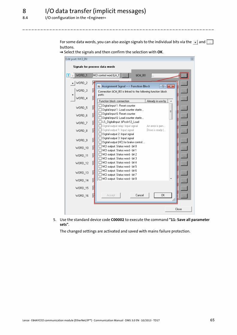
Lenze · E84AYCEO communication module (EtherNet/IP™) · Communication Manual · DMS 3.0 EN · 10/2013 · TD17 65
8 I/O data transfer (implicit messages)8.4 I/O configuration in the »Engineer«
_ _ _ _ _ _ _ _ _ _ _ _ _ _ _ _ _ _ _ _ _ _ _ _ _ _ _ _ _ _ _ _ _ _ _ _ _ _ _ _ _ _ _ _ _ _ _ _ _ _ _ _ _ _ _ _ _ _ _ _ _ _ _ _
For some data words, you can also assign signals to the individual bits via the and buttons. Select the signals and then confirm the selection with OK.
5. Use the standard device code C00002 to execute the command "11: Save all parameter sets".
The changed settings are activated and saved with mains failure protection.

8 I/O data transfer (implicit messages)8.4 I/O configuration in the »Engineer«
66 Lenze · E84AYCEO communication module (EtherNet/IP™) · Communication Manual · DMS 3.0 EN · 10/2013 · TD17
_ _ _ _ _ _ _ _ _ _ _ _ _ _ _ _ _ _ _ _ _ _ _ _ _ _ _ _ _ _ _ _ _ _ _ _ _ _ _ _ _ _ _ _ _ _ _ _ _ _ _ _ _ _ _ _ _ _ _ _ _ _ _ _
Preconfigured signal combination in the "FB Editor"
By setting the standard device code C00007 = "40: MCI" , the preconfigured signal combination isactivated.
The function block editor (FB Editor) is used to display the port blocks LP_MciIn and LP_MciOut withthe preconfigured signal combinations.
Here, you can also complement or change the signal combination.
Software manual / online help for the Inverter Drive 8400
Here you will find detailed information on the port/function block interconnection in the »Engineer« and on the port blocks.

Lenze · E84AYCEO communication module (EtherNet/IP™) · Communication Manual · DMS 3.0 EN · 10/2013 · TD17 67
8 I/O data transfer (implicit messages)8.4 I/O configuration in the »Engineer«
_ _ _ _ _ _ _ _ _ _ _ _ _ _ _ _ _ _ _ _ _ _ _ _ _ _ _ _ _ _ _ _ _ _ _ _ _ _ _ _ _ _ _ _ _ _ _ _ _ _ _ _ _ _ _ _ _ _ _ _ _ _ _ _
8.4.2 Configuring "AC Drive Profile" application
How to configure the "AC Drive Profile" application in the »Engineer«:
1. Select the "AC Drive Profile" application (C00005 = 1100) in the Application parameters tab.
2. Make the default setting of the I/O configuration.
Select "MCI" control mode (C00007 = 40).
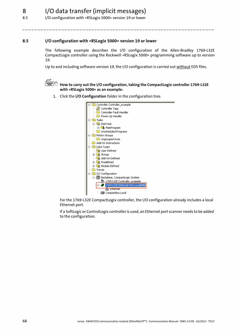
8 I/O data transfer (implicit messages)8.5 I/O configuration with »RSLogix 5000« version 19 or lower
68 Lenze · E84AYCEO communication module (EtherNet/IP™) · Communication Manual · DMS 3.0 EN · 10/2013 · TD17
_ _ _ _ _ _ _ _ _ _ _ _ _ _ _ _ _ _ _ _ _ _ _ _ _ _ _ _ _ _ _ _ _ _ _ _ _ _ _ _ _ _ _ _ _ _ _ _ _ _ _ _ _ _ _ _ _ _ _ _ _ _ _ _
8.5 I/O configuration with »RSLogix 5000« version 19 or lower
The following example describes the I/O configuration of the Allen-Bradley 1769-L32ECompactLogix controller using the Rockwell »RSLogix 5000« programming software up to version19.
Up to and including software version 19, the I/O configuration is carried out without EDS files.
How to carry out the I/O configuration, taking the CompactLogix controller 1769-L32E with »RSLogix 5000« as an example:
1. Click the I/O Configuration folder in the configuration tree.
For the 1769-L32E CompactLogix controller, the I/O configuration already includes a local Ethernet port.
If a SoftLogic or ControlLogix controller is used, an Ethernet port scanner needs to be added to the configuration.

Lenze · E84AYCEO communication module (EtherNet/IP™) · Communication Manual · DMS 3.0 EN · 10/2013 · TD17 69
8 I/O data transfer (implicit messages)8.5 I/O configuration with »RSLogix 5000« version 19 or lower
_ _ _ _ _ _ _ _ _ _ _ _ _ _ _ _ _ _ _ _ _ _ _ _ _ _ _ _ _ _ _ _ _ _ _ _ _ _ _ _ _ _ _ _ _ _ _ _ _ _ _ _ _ _ _ _ _ _ _ _ _ _ _ _
2. Right click on "Ethernet" and execute the "New Module ..." command from the context menu.
3. Open "Communications" and select "ETHERNET-MODULE | Generic Ethernet Module".
4. Confirm the selection with OK.

8 I/O data transfer (implicit messages)8.5 I/O configuration with »RSLogix 5000« version 19 or lower
70 Lenze · E84AYCEO communication module (EtherNet/IP™) · Communication Manual · DMS 3.0 EN · 10/2013 · TD17
_ _ _ _ _ _ _ _ _ _ _ _ _ _ _ _ _ _ _ _ _ _ _ _ _ _ _ _ _ _ _ _ _ _ _ _ _ _ _ _ _ _ _ _ _ _ _ _ _ _ _ _ _ _ _ _ _ _ _ _ _ _ _ _
5. Go to the "New Module" dialog window and define the properties of the newly added device .
The terms "input" and "output" refer to the point of view of the scanner:• Assembly input objects (input) are sent from the adapter to the scanner.• Assembly output objects (output) are sent from the scanner to the adapter.
Settings for Lenze technology applications or user-definable parameter sets:
If you use a Lenze technology application or an individual parameter set in the drive, you can exchange up to 16 user-definable words (INT) via the ports MCI_IN and MCI_OUT using
the assembly object instances "Input = 111" and "Output = 110".
Go to "Configuration" and enter the Assembly instance "130" and the Size "0".

Lenze · E84AYCEO communication module (EtherNet/IP™) · Communication Manual · DMS 3.0 EN · 10/2013 · TD17 71
8 I/O data transfer (implicit messages)8.5 I/O configuration with »RSLogix 5000« version 19 or lower
_ _ _ _ _ _ _ _ _ _ _ _ _ _ _ _ _ _ _ _ _ _ _ _ _ _ _ _ _ _ _ _ _ _ _ _ _ _ _ _ _ _ _ _ _ _ _ _ _ _ _ _ _ _ _ _ _ _ _ _ _ _ _ _
Settings for an "AC Drive Profile" application:
The assembly object instances "Input = 73" and "Output = 23" shown here exemplify the use of the AC Drive Profile "Extended Speed and Torque".
6. Complete the settings with OK.
Settings Description
Name Device name or type of the drive, usually with reference to the process (in the example "My_E84AYCEO")
Comm Format Data format for the assembly object instances ("connection parameters" area)
IP Address IP address of the drive• The IP address must be in the same subnetwork like the controller. (Depending on
the subnet mask; in general, the first 3 octets of the IP address must be identical.)• DNS is not supported; the host name merely describes the device.
Input Assembly object instance for input objects• Max. 16 input data words (32 bytes, 16 bits/word)• The number of input data must correspond to the length of the mapped ports in
the transmit PDO (PDO_TX0), otherwise the adapter will reject the connection with the error message "Invalid Target to Originator Size" (0x0128).
I/O data mapping ( 57)
Output Assembly object instance for output objects• Max. 16 output data words (32 bytes, 16 bits/word)• The number of output data must correspond to the length of the mapped ports
in the receive PDO (PDO_RX0), otherwise the adapter will reject the connection with the error message "Invalid Originator to Target Size" (0x0127).
I/O data mapping ( 57)
Configuration Select the Assembly instance "130" and the Size "0" for the configuration. These values are required!

8 I/O data transfer (implicit messages)8.5 I/O configuration with »RSLogix 5000« version 19 or lower
72 Lenze · E84AYCEO communication module (EtherNet/IP™) · Communication Manual · DMS 3.0 EN · 10/2013 · TD17
_ _ _ _ _ _ _ _ _ _ _ _ _ _ _ _ _ _ _ _ _ _ _ _ _ _ _ _ _ _ _ _ _ _ _ _ _ _ _ _ _ _ _ _ _ _ _ _ _ _ _ _ _ _ _ _ _ _ _ _ _ _ _ _
7. Under I/O Configuration in the configuration tree, right click "1769-L32E Ethernet Port LocalENB" and select "Properties".
8. Go to the Connection tab and set further properties.
Required setting
Optional settings
9. Complete the settings with OK.• The I/O configuration is now complete.• The corresponding tags will then be created in the "Controller Tags" of the controller
project.
10. The last step is Saving the I/O configuration in »RSLogix 5000« ( 83).
Setting Description
Requested Packet Interval (RPI)
Set RPI 4.0 ms. (Standard setting: 10 ms)The RPI [ms] specifies the intervals for the I/O data exchange between the drive (adapter) and the controller (scanner).
Settings Description
Inhibit module This option serves to interrupt or inhibit the communication to the adapter.
Major Fault On Controller If Connection Fails While In Run Mode
This option serves to put the controller into the error status if the EtherNet/IP connection to the drive fails while the controller is running.
Use Unicast Connection over EtherNet/IP
Option deactivated (standard setting):• The input data is sent from the adapter to the scanner by means of multicast
telegrams.• Other scanners can access this data in addition to the currently configured
scanner ("Listen only" or "Input only" connections).
Option activated:The input data is sent from the adapter to the scanner by means of unicast telegrams.

Lenze · E84AYCEO communication module (EtherNet/IP™) · Communication Manual · DMS 3.0 EN · 10/2013 · TD17 73
8 I/O data transfer (implicit messages)8.6 I/O configuration with »RSLogix 5000« version 20 or higher
_ _ _ _ _ _ _ _ _ _ _ _ _ _ _ _ _ _ _ _ _ _ _ _ _ _ _ _ _ _ _ _ _ _ _ _ _ _ _ _ _ _ _ _ _ _ _ _ _ _ _ _ _ _ _ _ _ _ _ _ _ _ _ _
8.6 I/O configuration with »RSLogix 5000« version 20 or higher
The following example describes the I/O configuration of the Allen-Bradley 1769-L32ECompactLogix controller using the Rockwell »RSLogix 5000« programming software from version20.
From software version 20 onwards, EDS files ( 37) are used for the I/O configuration.
How to carry out the I/O configuration, taking the CompactLogix controller 1769-L32E with »RSLogix 5000« as an example:
1. Use the "EDS Hardware Installation Tool" item to import the EDS files ( 37) of the EtherNet/IP nodes.
In »RSLogix 5000«, the dialog for the "EDS Hardware Installation Tool" is self-explanatory and not described further in this documentation.
2. Click the I/O Configuration folder in the configuration tree.
For the 1769-L32E CompactLogix controller, the I/O configuration already includes a local Ethernet port.
If a SoftLogic or ControlLogix controller is used, an Ethernet port scanner needs to be added to the configuration.

8 I/O data transfer (implicit messages)8.6 I/O configuration with »RSLogix 5000« version 20 or higher
74 Lenze · E84AYCEO communication module (EtherNet/IP™) · Communication Manual · DMS 3.0 EN · 10/2013 · TD17
_ _ _ _ _ _ _ _ _ _ _ _ _ _ _ _ _ _ _ _ _ _ _ _ _ _ _ _ _ _ _ _ _ _ _ _ _ _ _ _ _ _ _ _ _ _ _ _ _ _ _ _ _ _ _ _ _ _ _ _ _ _ _ _
3. Right click on "Ethernet" and execute the "New Module ..." command from the context menu.
4. Go to the "Select Module Type" dialog box and select "E84AYCEO" on the Catalog tab.
5. Confirm the selection with Create.
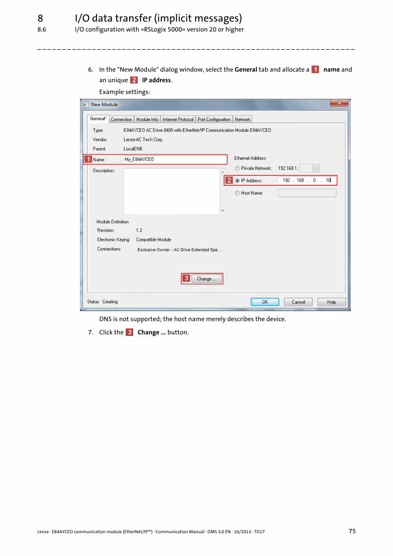
Lenze · E84AYCEO communication module (EtherNet/IP™) · Communication Manual · DMS 3.0 EN · 10/2013 · TD17 75
8 I/O data transfer (implicit messages)8.6 I/O configuration with »RSLogix 5000« version 20 or higher
_ _ _ _ _ _ _ _ _ _ _ _ _ _ _ _ _ _ _ _ _ _ _ _ _ _ _ _ _ _ _ _ _ _ _ _ _ _ _ _ _ _ _ _ _ _ _ _ _ _ _ _ _ _ _ _ _ _ _ _ _ _ _ _
6. In the "New Module" dialog window, select the General tab and allocate a name and
an unique IP address.
Example settings:
DNS is not supported; the host name merely describes the device.
7. Click the Change ... button.

8 I/O data transfer (implicit messages)8.6 I/O configuration with »RSLogix 5000« version 20 or higher
76 Lenze · E84AYCEO communication module (EtherNet/IP™) · Communication Manual · DMS 3.0 EN · 10/2013 · TD17
_ _ _ _ _ _ _ _ _ _ _ _ _ _ _ _ _ _ _ _ _ _ _ _ _ _ _ _ _ _ _ _ _ _ _ _ _ _ _ _ _ _ _ _ _ _ _ _ _ _ _ _ _ _ _ _ _ _ _ _ _ _ _ _
8. Go to the "Module Definition" dialog window and make the connection settings.
The terms "input" and "output" refer to the point of view of the scanner:• Assembly input objects (input) are sent from the adapter to the scanner.• Assembly output objects (output) are sent from the scanner to the adapter.
Settings for Lenze technology applications or user-definable parameter sets:
• Select "Exclusive Owner - Custom" connection.If you use the Lenze technology applications or user-definable parameter sets in the drive, the "Exclusive Owner - Custom" assembly object instance always has to be selected.
• Set Data type = INT.The INT data type is exchanged via the ports MCI_IN and MCI_OUT of the Inverter Drives 8400. In case of the SINT data type, an additional PLC logic is required for conversion.
• Set Tag Suffix = 1.A tag suffix formulates a module-describing tag name.

Lenze · E84AYCEO communication module (EtherNet/IP™) · Communication Manual · DMS 3.0 EN · 10/2013 · TD17 77
8 I/O data transfer (implicit messages)8.6 I/O configuration with »RSLogix 5000« version 20 or higher
_ _ _ _ _ _ _ _ _ _ _ _ _ _ _ _ _ _ _ _ _ _ _ _ _ _ _ _ _ _ _ _ _ _ _ _ _ _ _ _ _ _ _ _ _ _ _ _ _ _ _ _ _ _ _ _ _ _ _ _ _ _ _ _
Settings for an "AC Drive Profile" application:
• Select "AC Drive" connection.In the example, the AC Drive Profile "Exclusive Owner - AC Drive Ext. Speed & Torque" is used.
• Set Data type = INT.The INT data type is exchanged via the ports MCI_IN and MCI_OUT of the Inverter Drives 8400. In case of the SINT data type, an additional PLC logic is required for conversion.
• Set Tag Suffix = 1.A tag suffix formulates a module-describing tag name.
9. Complete the settings with OK.

8 I/O data transfer (implicit messages)8.6 I/O configuration with »RSLogix 5000« version 20 or higher
78 Lenze · E84AYCEO communication module (EtherNet/IP™) · Communication Manual · DMS 3.0 EN · 10/2013 · TD17
_ _ _ _ _ _ _ _ _ _ _ _ _ _ _ _ _ _ _ _ _ _ _ _ _ _ _ _ _ _ _ _ _ _ _ _ _ _ _ _ _ _ _ _ _ _ _ _ _ _ _ _ _ _ _ _ _ _ _ _ _ _ _ _
10. Open the "New Module" dialog window, select the Connection tab and set further properties.
"Name" displays the name of the connection set under 8..
The example shows an "Exclusive Owner - Custom" connection. According to this, the name of an"AC Drive Profile" connection may be displayed here too.
Required settings
Optional settings
Settings Description
Requested Packet Interval (RPI)
Set RPI 4.0 ms. (Standard: 10 ms)The RPI [ms] specifies the intervals for the I/O data exchange between the drive (adapter) and the controller (scanner).
Input type Select the "Multicast" input type.• The input data is sent from the adapter to the scanner by means of multicast
telegrams.• Other scanners can access this data in addition to the currently configured
scanner ("Listen only" or "Input only" connections).
Settings Description
Inhibit module This option serves to interrupt or inhibit the communication to the adapter.
Major Fault On Controller If Connection Fails While In Run Mode
This option serves to put the controller into the error status if the EtherNet/IP connection to the drive fails while the controller is running.
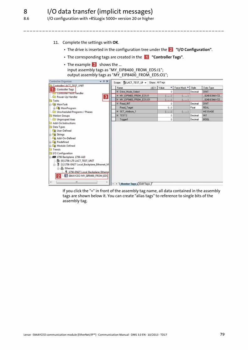
Lenze · E84AYCEO communication module (EtherNet/IP™) · Communication Manual · DMS 3.0 EN · 10/2013 · TD17 79
8 I/O data transfer (implicit messages)8.6 I/O configuration with »RSLogix 5000« version 20 or higher
_ _ _ _ _ _ _ _ _ _ _ _ _ _ _ _ _ _ _ _ _ _ _ _ _ _ _ _ _ _ _ _ _ _ _ _ _ _ _ _ _ _ _ _ _ _ _ _ _ _ _ _ _ _ _ _ _ _ _ _ _ _ _ _
11. Complete the settings with OK.
• The drive is inserted in the configuration tree under the "I/O Configuration".
• The corresponding tags are created in the "Controller Tags".
• The example shows the ...input assembly tags as "MY_EIP8400_FROM_EDS:I1";output assembly tags as "MY_EIP8400_FROM_EDS:O1";
If you click the "+" in front of the assembly tag name, all data contained in the assembly tags are shown below it. You can create "alias tags" to reference to single bits of the assembly tag.

8 I/O data transfer (implicit messages)8.6 I/O configuration with »RSLogix 5000« version 20 or higher
80 Lenze · E84AYCEO communication module (EtherNet/IP™) · Communication Manual · DMS 3.0 EN · 10/2013 · TD17
_ _ _ _ _ _ _ _ _ _ _ _ _ _ _ _ _ _ _ _ _ _ _ _ _ _ _ _ _ _ _ _ _ _ _ _ _ _ _ _ _ _ _ _ _ _ _ _ _ _ _ _ _ _ _ _ _ _ _ _ _ _ _ _
12. Create an "alias tag".
Example with the assembly object instance 23 (0x17):
For a forward motion of a conveyor, bit ’0’ (Run Fwd) is to be referenced by byte ’0’.
Right-click an assembly tag and select the command "New Tag..." in the context menu.
Instance Byte Bit 7 Bit 6 Bit 5 Bit 4 Bit 3 Bit 2 Bit 1 Bit 0
23(0x17)
0 NetRef
NetCtrl FaultReset
RunRev
RunFwd
1
2 Speed Reference (Low Byte)
3 Speed Reference (High Byte)
4 Torque Reference (Low Byte)
5 Torque Reference (High Byte)
Note!
• NetCtrl (Bit 5) and NetRef (Bit 6) have to be set in order that the drive can receive start/stop commands and speed/torque command via the network.
• In order to be able to use the torque control of the assembly object distance 23 (0x17), the "DriveMode" attribute has to be written by means of explicit message transmission.Write "DriveMode" attribute ( 154)

Lenze · E84AYCEO communication module (EtherNet/IP™) · Communication Manual · DMS 3.0 EN · 10/2013 · TD17 81
8 I/O data transfer (implicit messages)8.6 I/O configuration with »RSLogix 5000« version 20 or higher
_ _ _ _ _ _ _ _ _ _ _ _ _ _ _ _ _ _ _ _ _ _ _ _ _ _ _ _ _ _ _ _ _ _ _ _ _ _ _ _ _ _ _ _ _ _ _ _ _ _ _ _ _ _ _ _ _ _ _ _ _ _ _ _
13. Go to the "New Tag" dialog window and ...
• assign a Name for the tag (in the example: "Conveyor_1_RUN_FWD");
• set Type = "Alias";
• select the Alias address which is to be referenced for the alias tag.(in the example: "MY_EIP8400_FROM_EDS:O1.Data(0).0" (bit ’0’ of byte ’0’)

8 I/O data transfer (implicit messages)8.6 I/O configuration with »RSLogix 5000« version 20 or higher
82 Lenze · E84AYCEO communication module (EtherNet/IP™) · Communication Manual · DMS 3.0 EN · 10/2013 · TD17
_ _ _ _ _ _ _ _ _ _ _ _ _ _ _ _ _ _ _ _ _ _ _ _ _ _ _ _ _ _ _ _ _ _ _ _ _ _ _ _ _ _ _ _ _ _ _ _ _ _ _ _ _ _ _ _ _ _ _ _ _ _ _ _
14. Confirm the settings with the Create button.
The alias tag "Conveyor_1_RUN_FWD" is created below the "Controller Tags":
15. The last step is Saving the I/O configuration in »RSLogix 5000« ( 83).
Name Value Force Mask Style Data Type
. . . . . . . . . . . . . . .
[–] MY_EIP8400_FROM_EDS:O1 {. . .} {. . .} _024B:E84AYCE...
[+] MY_EIP8400_FROM_EDS:O1.Data[1] 0 Decimal SINT
[+] MY_EIP8400_FROM_EDS:O1.Data[2] 0 Decimal SINT
[+] MY_EIP8400_FROM_EDS:O1.Data[3] 0 Decimal SINT
[+] MY_EIP8400_FROM_EDS:O1.Data[4] 0 Decimal SINT
[+] MY_EIP8400_FROM_EDS:O1.Data[5] 0 Decimal SINT
Conveyor_1_RUN_FWD 0 Decimal BOOL

Lenze · E84AYCEO communication module (EtherNet/IP™) · Communication Manual · DMS 3.0 EN · 10/2013 · TD17 83
8 I/O data transfer (implicit messages)8.7 Saving the I/O configuration in »RSLogix 5000«
_ _ _ _ _ _ _ _ _ _ _ _ _ _ _ _ _ _ _ _ _ _ _ _ _ _ _ _ _ _ _ _ _ _ _ _ _ _ _ _ _ _ _ _ _ _ _ _ _ _ _ _ _ _ _ _ _ _ _ _ _ _ _ _
8.7 Saving the I/O configuration in »RSLogix 5000«
After adding the scanner and the adapter to the I/O configuration, the configuration must bedownloaded to the controller. The configuration file should also be saved on your computer.
How to save the I/O configuration:
1. Select the menu command CommunicationsDownload.• The "Download" dialog box will open.• If a message box reports that »RSLogix 5000« is unable to go online, select the menu
command CommunicationsCommunications Who Active and try to find your controller in the "Who Active" dialog box. If the controller is not shown there, the EtherNet/IP driver needs to be added to »RSLinx« or configured in »RSLinx«. For more information, please refer to the »RSLinx« online help.
2. Click the Download button.• The I/O configuration is downloaded to the controller.• When the download has been successfully completed, »RSLogix 5000« changes to online
mode and the I/O OK box in the upper left of the screen is green.
3. Select the menu command FileSave.• If this is the first time the I/O configuration is saved, the "Save As" dialog box will open.• Select a folder and enter a file name to save the configuration to a file on your computer.• Finally, click the Save button.

9 Parameter data transfer (explicit messages)
84 Lenze · E84AYCEO communication module (EtherNet/IP™) · Communication Manual · DMS 3.0 EN · 10/2013 · TD17
_ _ _ _ _ _ _ _ _ _ _ _ _ _ _ _ _ _ _ _ _ _ _ _ _ _ _ _ _ _ _ _ _ _ _ _ _ _ _ _ _ _ _ _ _ _ _ _ _ _ _ _ _ _ _ _ _ _ _ _ _ _ _ _
9 Parameter data transfer (explicit messages)
An "explicit message" is a logical instruction in the PLC program used for messaging. It can be usedto read or write to either a parameter setting or the data of an assembly object.
For all Allen-Bradley devices of the CompactLogix, ControlLogix and SoftLogix series, the MSGinstruction provides the application possibilities described in this chapter. For other PLC types,please consult the programming documentation for the corresponding PLC.
Note!
When you use several MSG BLOCKs per adapter, you can work resource-friendly by sequential triggering and hold available enough communication reserves in the EtherNet/IP module for further possible clients.
Application note
An example of parameter data transfer (read/write parameters) in a "AC Drive Profile" application can be found in the download area (Application Knowledge Base) at www.Lenze.com.

Lenze · E84AYCEO communication module (EtherNet/IP™) · Communication Manual · DMS 3.0 EN · 10/2013 · TD17 85
9 Parameter data transfer (explicit messages)9.1 Write parameters
_ _ _ _ _ _ _ _ _ _ _ _ _ _ _ _ _ _ _ _ _ _ _ _ _ _ _ _ _ _ _ _ _ _ _ _ _ _ _ _ _ _ _ _ _ _ _ _ _ _ _ _ _ _ _ _ _ _ _ _ _ _ _ _
9.1 Write parameters
In order to write data into code C00011 (reference speed) of the Inverter Drive 8400 by means ofexplicit message transfer, for example, the following settings are necessary:
Settings Value / description
Message Type "CIP Generic"
Service Type "Set Attribute Single" (service code "0x10")
Class "6E" (access to Lenze code)
Instance "11" = Lenze code C00011 of Inverter Drive 8400
Attribute "1" = Subcode of the Lenze code• If the corresponding Lenze code does not have a subcode, the value ’1’
must be entered here.• A display code cannot be configured by the "SET" service.
Source Element Variable in the PLC program used as data source for writing.
Source Length The source length has to be set to the length (data type) of the current parameter (see parameter reference in the software manual/online help of the inverter).For writing to code C00011, set the source length to "2 bytes".

9 Parameter data transfer (explicit messages)9.2 Read parameters
86 Lenze · E84AYCEO communication module (EtherNet/IP™) · Communication Manual · DMS 3.0 EN · 10/2013 · TD17
_ _ _ _ _ _ _ _ _ _ _ _ _ _ _ _ _ _ _ _ _ _ _ _ _ _ _ _ _ _ _ _ _ _ _ _ _ _ _ _ _ _ _ _ _ _ _ _ _ _ _ _ _ _ _ _ _ _ _ _ _ _ _ _
9.2 Read parameters
In order to read out Lenze code C00011 (reference speed) of the Inverter Drive 8400 by means ofexplicit message transfer, for example, the following settings are necessary:
Settings Value / description
Message Type "CIP Generic"
Service Type "Get Attribute Single" (service code "0x0E")
Class "6E" (access to to Lenze code)
Instance "11" = Lenze code C00011 of Inverter Drive 8400
Attribute "1" = Subcode of the Lenze codeIf the corresponding Lenze code does not have a subcode, the value ’1’ must be entered here.
Destination Variable in the PLC program the drive data will be copied to.When reading code C00011, make sure that the tag used as destination is a single word in UINT16 format.

Lenze · E84AYCEO communication module (EtherNet/IP™) · Communication Manual · DMS 3.0 EN · 10/2013 · TD17 87
9 Parameter data transfer (explicit messages)9.2 Read parameters
_ _ _ _ _ _ _ _ _ _ _ _ _ _ _ _ _ _ _ _ _ _ _ _ _ _ _ _ _ _ _ _ _ _ _ _ _ _ _ _ _ _ _ _ _ _ _ _ _ _ _ _ _ _ _ _ _ _ _ _ _ _ _ _
For every "explicit message", the path for sending the message via the Ethernet port of the PLC tothe IP address of the drive needs to be set under the Communication tab. This path depends on thePLC used.
If you need assistance with the setting of this path, please consult the PLC manufacturer.
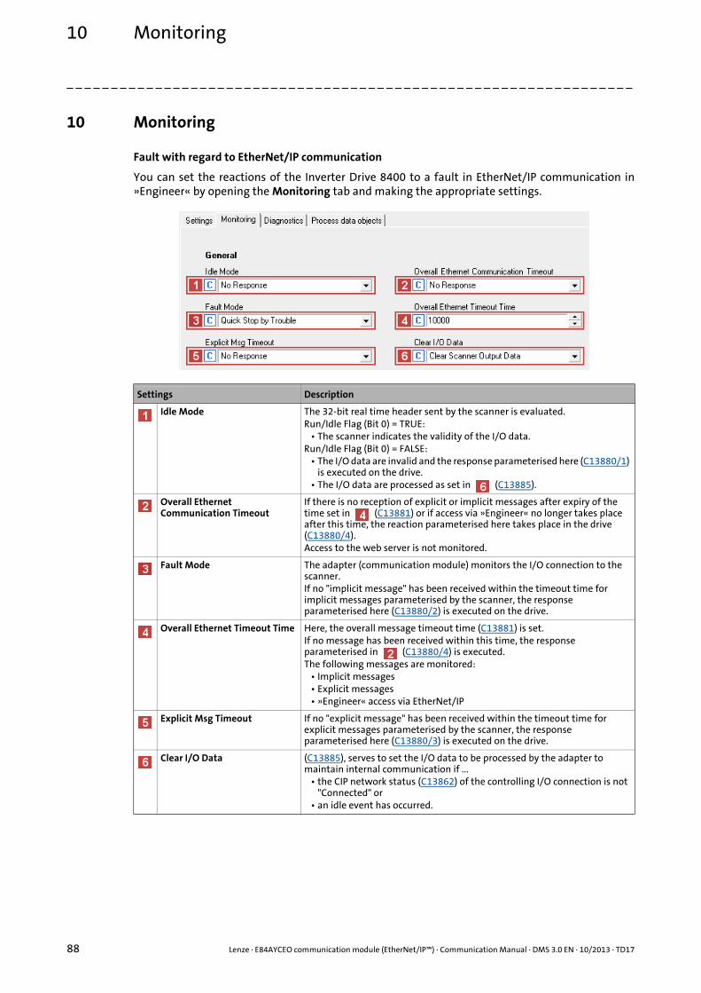
10 Monitoring
88 Lenze · E84AYCEO communication module (EtherNet/IP™) · Communication Manual · DMS 3.0 EN · 10/2013 · TD17
_ _ _ _ _ _ _ _ _ _ _ _ _ _ _ _ _ _ _ _ _ _ _ _ _ _ _ _ _ _ _ _ _ _ _ _ _ _ _ _ _ _ _ _ _ _ _ _ _ _ _ _ _ _ _ _ _ _ _ _ _ _ _ _
10 Monitoring
Fault with regard to EtherNet/IP communication
You can set the reactions of the Inverter Drive 8400 to a fault in EtherNet/IP communication in»Engineer« by opening the Monitoring tab and making the appropriate settings.
Settings Description
Idle Mode The 32-bit real time header sent by the scanner is evaluated.Run/Idle Flag (Bit 0) = TRUE:
• The scanner indicates the validity of the I/O data.Run/Idle Flag (Bit 0) = FALSE:
• The I/O data are invalid and the response parameterised here (C13880/1) is executed on the drive.
• The I/O data are processed as set in (C13885).
Overall Ethernet Communication Timeout
If there is no reception of explicit or implicit messages after expiry of the time set in (C13881) or if access via »Engineer« no longer takes place after this time, the reaction parameterised here takes place in the drive (C13880/4).Access to the web server is not monitored.
Fault Mode The adapter (communication module) monitors the I/O connection to the scanner.If no "implicit message" has been received within the timeout time for implicit messages parameterised by the scanner, the response parameterised here (C13880/2) is executed on the drive.
Overall Ethernet Timeout Time Here, the overall message timeout time (C13881) is set.If no message has been received within this time, the response parameterised in (C13880/4) is executed.The following messages are monitored:
• Implicit messages• Explicit messages• »Engineer« access via EtherNet/IP
Explicit Msg Timeout If no "explicit message" has been received within the timeout time for explicit messages parameterised by the scanner, the response parameterised here (C13880/3) is executed on the drive.
Clear I/O Data (C13885), serves to set the I/O data to be processed by the adapter to maintain internal communication if ...
• the CIP network status (C13862) of the controlling I/O connection is not "Connected" or
• an idle event has occurred.
Lenze · E84AYCEO communication module (EtherNet/IP™) · Communication Manual · DMS 3.0 EN · 10/2013 · TD17 89
11 Diagnostics11.1 LED status displays
_ _ _ _ _ _ _ _ _ _ _ _ _ _ _ _ _ _ _ _ _ _ _ _ _ _ _ _ _ _ _ _ _ _ _ _ _ _ _ _ _ _ _ _ _ _ _ _ _ _ _ _ _ _ _ _ _ _ _ _ _ _ _ _
11 Diagnostics
The LEDs on the front of the communication module serve to diagnose faults. Moreover, the»Engineer« serves to show diagnostic information.
11.1 LED status displays
The following status displays are distinguished:
• Module status displays ( 90)
• CIP™ status displays ( 91)
• Status indicators at the RJ45 sockets (X259, X260) ( 94)
Note!
LED status displays for trouble-free operation:• The LEDs MS ( 90) and NS ( 91) light up permanently.• On the RJ45 sockets X259 and X260, the green LEDs are lit and the yellow LEDs are
blinking or jittering ( 94).

11 Diagnostics11.1 LED status displays
90 Lenze · E84AYCEO communication module (EtherNet/IP™) · Communication Manual · DMS 3.0 EN · 10/2013 · TD17
_ _ _ _ _ _ _ _ _ _ _ _ _ _ _ _ _ _ _ _ _ _ _ _ _ _ _ _ _ _ _ _ _ _ _ _ _ _ _ _ _ _ _ _ _ _ _ _ _ _ _ _ _ _ _ _ _ _ _ _ _ _ _ _
11.1.1 Module status displays
Module states are indicated by the ST, ER and DE LEDs.
[11-1] LEDs ST, ER, DE
E84AYCEO007_a
ST
ER
DE
LED Colour Status Description
ST Green On
The communication module is supplied with voltage and is connected to the standard device.
Blinking
The communication module is supplied with voltage, but is not connected to the standard device. (Standard device is switched off, in the initialisation phase, or not available.)
ER Red On
An error has occurred in the communication module.
DE Red On
The communication module is not accepted by the basic device or the basic device is not active (see notes in the documentation relating to the basic device.)
250 ms
250 ms

Lenze · E84AYCEO communication module (EtherNet/IP™) · Communication Manual · DMS 3.0 EN · 10/2013 · TD17 91
11 Diagnostics11.1 LED status displays
_ _ _ _ _ _ _ _ _ _ _ _ _ _ _ _ _ _ _ _ _ _ _ _ _ _ _ _ _ _ _ _ _ _ _ _ _ _ _ _ _ _ _ _ _ _ _ _ _ _ _ _ _ _ _ _ _ _ _ _ _ _ _ _
11.1.2 CIP™ status displays
CIP statuses are indicated by the MS and NS LEDs.
[11-2] LEDs MS, NS
E84AYCEO007_b
MS
NS

11 Diagnostics11.1 LED status displays
92 Lenze · E84AYCEO communication module (EtherNet/IP™) · Communication Manual · DMS 3.0 EN · 10/2013 · TD17
_ _ _ _ _ _ _ _ _ _ _ _ _ _ _ _ _ _ _ _ _ _ _ _ _ _ _ _ _ _ _ _ _ _ _ _ _ _ _ _ _ _ _ _ _ _ _ _ _ _ _ _ _ _ _ _ _ _ _ _ _ _ _ _
LED Colour / status Description
MS Green Red
Off Off CIP module status: "Nonexistent"The communication module is not being supplied with voltage.
Off On
CIP module status: "Major Unrecoverable Fault"The communication module has a fault that cannot be rectified.The status is set if the pending status determining device error shows the "System fault" response.
Off Blinking
CIP module status: "Major Recoverable Fault"The communication module has a fault that can be rectified.The status is set if the pending status determining device error shows the "Fault", "Trouble", "Quick stop by trouble", "Warning locked", or "Warning" response.
On Off
CIP module status: "Operational"The communication module is working perfectly.
Blinking Off
CIP module status: "Standby"The communication module has not been completely configured or the configuration is defective.
Blinking Blinking
CIP module status: "Device Self Testing"The communication module is currently undergoing a self-test.
250 ms
250 ms
250 ms
250 ms
250 ms
250 ms
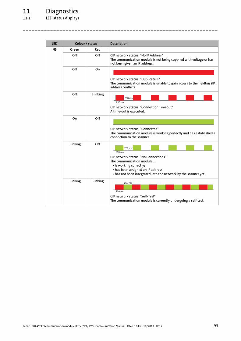
Lenze · E84AYCEO communication module (EtherNet/IP™) · Communication Manual · DMS 3.0 EN · 10/2013 · TD17 93
11 Diagnostics11.1 LED status displays
_ _ _ _ _ _ _ _ _ _ _ _ _ _ _ _ _ _ _ _ _ _ _ _ _ _ _ _ _ _ _ _ _ _ _ _ _ _ _ _ _ _ _ _ _ _ _ _ _ _ _ _ _ _ _ _ _ _ _ _ _ _ _ _
NS Green Red
Off Off CIP network status: "No IP Address"The communication module is not being supplied with voltage or has not been given an IP address.
Off On
CIP network status: "Duplicate IP"The communication module is unable to gain access to the fieldbus (IP address conflict).
Off Blinking
CIP network status: "Connection Timeout"A time-out is executed.
On Off
CIP network status: "Connected"The communication module is working perfectly and has established a connection to the scanner.
Blinking Off
CIP network status: "No Connections"The communication module ...
• is working correctly;• has been assigned an IP address;• has not been integrated into the network by the scanner yet.
Blinking Blinking
CIP network status: "Self-Test"The communication module is currently undergoing a self-test.
LED Colour / status Description
250 ms
250 ms
250 ms
250 ms
250 ms
250 ms

11 Diagnostics11.1 LED status displays
94 Lenze · E84AYCEO communication module (EtherNet/IP™) · Communication Manual · DMS 3.0 EN · 10/2013 · TD17
_ _ _ _ _ _ _ _ _ _ _ _ _ _ _ _ _ _ _ _ _ _ _ _ _ _ _ _ _ _ _ _ _ _ _ _ _ _ _ _ _ _ _ _ _ _ _ _ _ _ _ _ _ _ _ _ _ _ _ _ _ _ _ _
11.1.3 Status indicators at the RJ45 sockets (X259, X260)
The LEDs at RJ45 sockets X259 and X260 indicate the status of the Ethernet connection.
[11-3] LEDs Link , Act
E84YCEO003C
Link
Act
Link Act
LED Colour Status Description
Link Green Off No Ethernet connection
On
There is a physical Ethernet connection.
Act Yellow Off No Ethernet data transfer
On or flickers
Data are being exchanged via Ethernet.
50 ms

Lenze · E84AYCEO communication module (EtherNet/IP™) · Communication Manual · DMS 3.0 EN · 10/2013 · TD17 95
11 Diagnostics11.2 Diagnostics with the »Engineer«
_ _ _ _ _ _ _ _ _ _ _ _ _ _ _ _ _ _ _ _ _ _ _ _ _ _ _ _ _ _ _ _ _ _ _ _ _ _ _ _ _ _ _ _ _ _ _ _ _ _ _ _ _ _ _ _ _ _ _ _ _ _ _ _
11.2 Diagnostics with the »Engineer«
In the »Engineer«, the Diagnostics tab displays various pieces of EtherNet/IP diagnosticinformation.
Display Code
MAC-ID C13003
Active IP Address C13010
Active Subnetwork Mask C13011
Active Gateway Address C13012
Active multicast IP address C13016
Process data C13850, C13851, C13852, C13853
CIP Module Status C13861
CIP Network Status C13862
Ethernet Port X259 connection status C13863/1
Ethernet Port X260 connection status C13863/2

12 Error messages12.1 Short overview of the EtherNet/IP error messages
96 Lenze · E84AYCEO communication module (EtherNet/IP™) · Communication Manual · DMS 3.0 EN · 10/2013 · TD17
_ _ _ _ _ _ _ _ _ _ _ _ _ _ _ _ _ _ _ _ _ _ _ _ _ _ _ _ _ _ _ _ _ _ _ _ _ _ _ _ _ _ _ _ _ _ _ _ _ _ _ _ _ _ _ _ _ _ _ _ _ _ _ _
12 Error messages
This chapter supplements the error list in the software manual and in the »Engineer« online helpsystem for the Inverter Drive 8400 by adding the EtherNet/IP error messages to the list.
12.1 Short overview of the EtherNet/IP error messages
The following table lists all EtherNet/IP error messages in the numerical order of the error numbers.Furthermore, the preset error response and - if available - the parameter for setting the errorresponse are specified.
Tip!
If you click on the cross-reference in the first column, you will get a detailed description(causes and remedies) of the corresponding error message.
Software manual/»Engineer« online help for Inverter Drives 8400
Here you will find general information on diagnostics & fault analysis and on error messages.
Error no.[hex]
Subject area no.[dec]
Error no.[dec]
Error text Error type(Error response)
Adjustable in
0x01bc3100 444 12544 EtherNet/IP: Exist. connect. to 8400 lost 0: No Response -
0x01bc5531 444 21809 EtherNet/IP: Memory: No Access 1: No Response -
0x01bc5532 444 21810 EtherNet/IP: Memory: Read Error 1: No Response -
0x01bc5533 444 21811 EtherNet/IP: Memory: Write Error 1: No Response -
0x01bc6010 444 24592 EtherNet/IP: Restart by Watchdogreset 1: No Response -
0x01bc6011 444 24593 EtherNet/IP: Internal Error 1: No Response -
0x01bc6100 444 24832 EtherNet/IP: Internal Error 1: No Response -
0x01bc6101 444 24833 EtherNet/IP: Internal Error 1: No Response -
0x01bc641f 444 25631 EtherNet/IP: Invalid Parameter Set 1: No Response -
0x01bc6420 444 25632 EtherNet/IP: Error: Lenze Setting Loaded 1: No Response -
0x01bc6430 444 25648 EtherNet/IP: Invalid Configuration 1: No Response -
0x01bc6533 444 25907 EtherNet/IP: Invalid IP Parameter 1: No Response -
0x01bc8111 444 33041 EtherNet/IP: Fault Mode 1: No Response C13880/2
0x01bc8112 444 33042 EtherNet/IP: Explicit Message Timeout 0: No Response C13880/3
0x01bc8114 444 33044 EtherNet/IP: Overall Ethernet Timeout 0: No Response C13880/4
0x01bc8121 444 33057 EtherNet/IP: Ethernet cable pulled out 1: No Response -
0x01bc8132 444 33074 EtherNet/IP: Idle Mode 0: No Response C13880/1
0x01bc8273 444 33395 EtherNet/IP: Duplicate IP Address 1: No Response -

Lenze · E84AYCEO communication module (EtherNet/IP™) · Communication Manual · DMS 3.0 EN · 10/2013 · TD17 97
12 Error messages12.2 Possible causes and remedies
_ _ _ _ _ _ _ _ _ _ _ _ _ _ _ _ _ _ _ _ _ _ _ _ _ _ _ _ _ _ _ _ _ _ _ _ _ _ _ _ _ _ _ _ _ _ _ _ _ _ _ _ _ _ _ _ _ _ _ _ _ _ _ _
12.2 Possible causes and remedies
In this chapter, all EtherNet/IP error messages are listed in the numerical order of the error numbers.Possible causes and remedies as well as responses to the error messages are described in detail.
EtherNet/IP: Exist. connect. to 8400 lost [0x01bc3100]
EtherNet/IP: Memory: No Access [0x01bc5531]
EtherNet/IP: Memory: Read Error [0x01bc5532]
EtherNet/IP: Memory: Write Error [0x01bc5533]
EtherNet/IP: Restart by Watchdogreset [0x01bc6010]
Response (Lenze setting printed in bold) Setting: not possible
None System fault Fault Trouble Quick stop by trouble Warning locked Warning Information
Cause Remedy
• The communication module is being supplied with external voltage but the Inverter Drive 8400 is not being supplied with voltage.
• The communication module has not been correctly connected to the Inverter Drive 8400.
• Supply the Inverter Drive 8400 with voltage.• Securely connect the communication module to the
Inverter Drive 8400.
Response (Lenze setting printed in bold) Setting: not possible
None System fault Fault Trouble Quick stop by trouble Warning locked Warning Information
Cause Remedy
Access to memory was not possible. Send communication module together with a description of the fault to Lenze.
Response (Lenze setting printed in bold) Setting: not possible
None System fault Fault Trouble Quick stop by trouble Warning locked Warning Information
Cause Remedy
Parameter could not be read. • Download application again (including module).• Send communication module together with a
description of the fault to Lenze.
Response (Lenze setting printed in bold) Setting: not possible
None System fault Fault Trouble Quick stop by trouble Warning locked Warning Information
Cause Remedy
Parameter could not be written. • Download application again (including module).• Send communication module together with a
description of the fault to Lenze.
Response (Lenze setting printed in bold) Setting: not possible
None System fault Fault Trouble Quick stop by trouble Warning locked Warning Information
Cause Remedy
Communication module is defective. Send communication module with error description to Lenze.
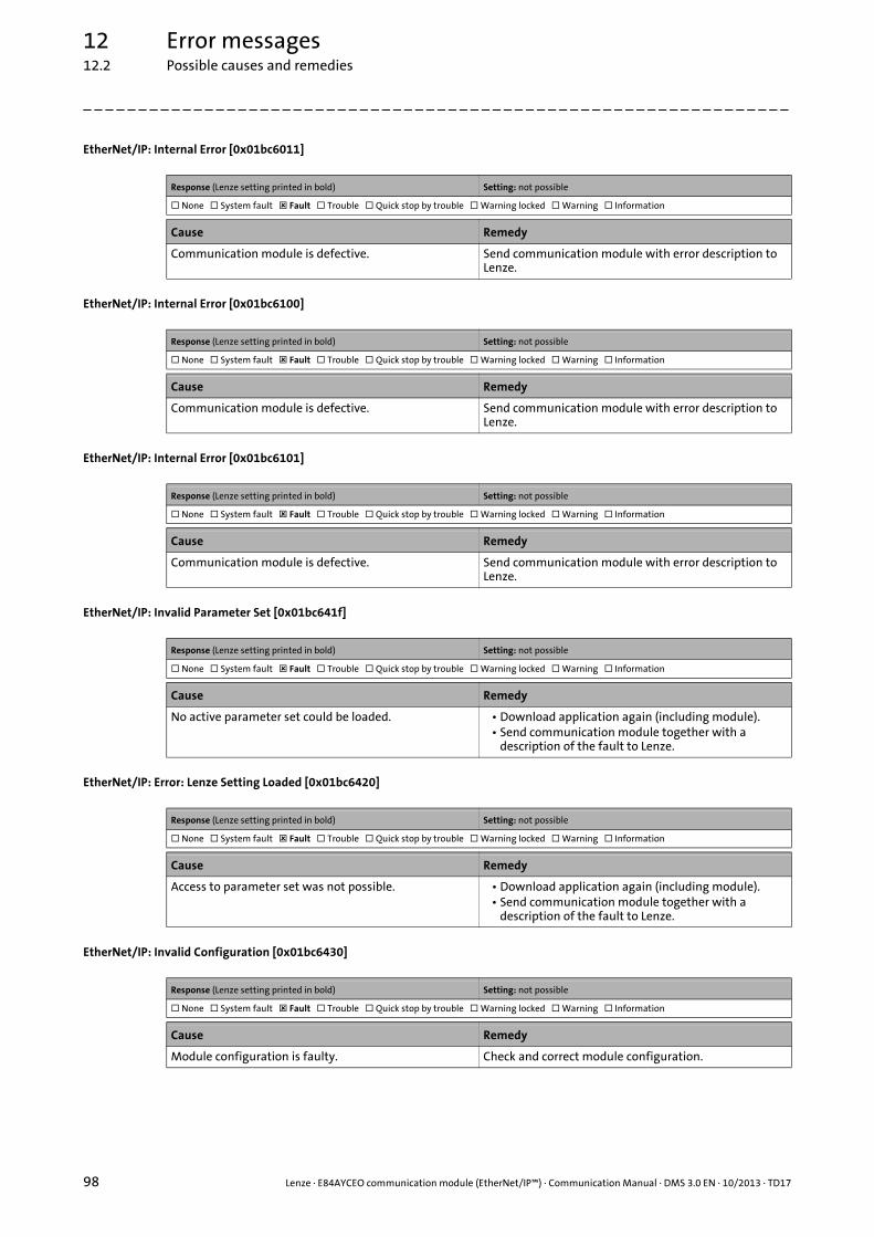
12 Error messages12.2 Possible causes and remedies
98 Lenze · E84AYCEO communication module (EtherNet/IP™) · Communication Manual · DMS 3.0 EN · 10/2013 · TD17
_ _ _ _ _ _ _ _ _ _ _ _ _ _ _ _ _ _ _ _ _ _ _ _ _ _ _ _ _ _ _ _ _ _ _ _ _ _ _ _ _ _ _ _ _ _ _ _ _ _ _ _ _ _ _ _ _ _ _ _ _ _ _ _
EtherNet/IP: Internal Error [0x01bc6011]
EtherNet/IP: Internal Error [0x01bc6100]
EtherNet/IP: Internal Error [0x01bc6101]
EtherNet/IP: Invalid Parameter Set [0x01bc641f]
EtherNet/IP: Error: Lenze Setting Loaded [0x01bc6420]
EtherNet/IP: Invalid Configuration [0x01bc6430]
Response (Lenze setting printed in bold) Setting: not possible
None System fault Fault Trouble Quick stop by trouble Warning locked Warning Information
Cause Remedy
Communication module is defective. Send communication module with error description to Lenze.
Response (Lenze setting printed in bold) Setting: not possible
None System fault Fault Trouble Quick stop by trouble Warning locked Warning Information
Cause Remedy
Communication module is defective. Send communication module with error description to Lenze.
Response (Lenze setting printed in bold) Setting: not possible
None System fault Fault Trouble Quick stop by trouble Warning locked Warning Information
Cause Remedy
Communication module is defective. Send communication module with error description to Lenze.
Response (Lenze setting printed in bold) Setting: not possible
None System fault Fault Trouble Quick stop by trouble Warning locked Warning Information
Cause Remedy
No active parameter set could be loaded. • Download application again (including module).• Send communication module together with a
description of the fault to Lenze.
Response (Lenze setting printed in bold) Setting: not possible
None System fault Fault Trouble Quick stop by trouble Warning locked Warning Information
Cause Remedy
Access to parameter set was not possible. • Download application again (including module).• Send communication module together with a
description of the fault to Lenze.
Response (Lenze setting printed in bold) Setting: not possible
None System fault Fault Trouble Quick stop by trouble Warning locked Warning Information
Cause Remedy
Module configuration is faulty. Check and correct module configuration.
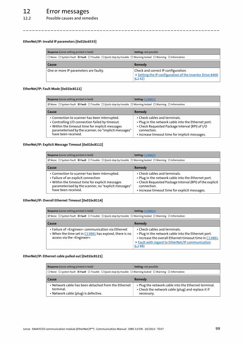
Lenze · E84AYCEO communication module (EtherNet/IP™) · Communication Manual · DMS 3.0 EN · 10/2013 · TD17 99
12 Error messages12.2 Possible causes and remedies
_ _ _ _ _ _ _ _ _ _ _ _ _ _ _ _ _ _ _ _ _ _ _ _ _ _ _ _ _ _ _ _ _ _ _ _ _ _ _ _ _ _ _ _ _ _ _ _ _ _ _ _ _ _ _ _ _ _ _ _ _ _ _ _
EtherNet/IP: Invalid IP parameters [0x01bc6533]
EtherNet/IP: Fault Mode [0x01bc8111]
EtherNet/IP: Explicit Message Timeout [0x01bc8112]
EtherNet/IP: Overall Ethernet Timeout [0x01bc8114]
EtherNet/IP: Ethernet cable pulled out [0x01bc8121]
Response (Lenze setting printed in bold) Setting: not possible
None System fault Fault Trouble Quick stop by trouble Warning locked Warning Information
Cause Remedy
One or more IP parameters are faulty. Check and correct IP configuration.Setting the IP configuration of the Inverter Drive 8400 ( 42)
Response (Lenze setting printed in bold) Setting: C13880/2
None System fault Fault Trouble Quick stop by trouble Warning locked Warning Information
Cause Remedy
• Connection to scanner has been interrupted.• Controlling I/O connection failed by timeout.• Within the timeout time for implicit messages
parameterised by the scanner, no "implicit messages" have been received.
• Check cables and terminals.• Plug in the network cable into the Ethernet port.• Check Requested Package Interval (RPI) of I/O
connection.• Increase timeout time for implicit messages.
Response (Lenze setting printed in bold) Setting: C13880/3
None System fault Fault Trouble Quick stop by trouble Warning locked Warning Information
Cause Remedy
• Connection to scanner has been interrupted.• Failure of an explicit connection• Within the timeout time for explicit messages
parameterised by the scanner, no "explicit messages" have been received.
• Check cables and terminals.• Plug in the network cable into the Ethernet port.• Check Requested Package Interval (RPI) of the explicit
connection.• Increase timeout time for explicit messages.
Response (Lenze setting printed in bold) Setting: C13880/4
None System fault Fault Trouble Quick stop by trouble Warning locked Warning Information
Cause Remedy
• Failure of »Engineer« communication via Ethernet• When the time set in C13881 has expired, there is no
access via the »Engineer«.
• Check cables and terminals.• Plug in the network cable into the Ethernet port.• Increase the overall Ethernet timeout time in C13881.Fault with regard to EtherNet/IP communication ( 88)
Response (Lenze setting printed in bold) Setting: not possible
None system fault Fault Trouble Quick stop by trouble Warning locked Warning Information
Cause Remedy
• Network cable has been detached from the Ethernet terminal.
• Network cable (plug) is defective.
• Plug the network cable into the Ethernet terminal.• Check the network cable (plug) and replace it if
necessary.

12 Error messages12.2 Possible causes and remedies
100 Lenze · E84AYCEO communication module (EtherNet/IP™) · Communication Manual · DMS 3.0 EN · 10/2013 · TD17
_ _ _ _ _ _ _ _ _ _ _ _ _ _ _ _ _ _ _ _ _ _ _ _ _ _ _ _ _ _ _ _ _ _ _ _ _ _ _ _ _ _ _ _ _ _ _ _ _ _ _ _ _ _ _ _ _ _ _ _ _ _ _ _
EtherNet/IP: Idle Mode [0x01bc8132]
EtherNet/IP: Duplicate IP Address [0x01bc8273]
Response (Lenze setting printed in bold) Setting: C13880/1
None system fault Fault Trouble Quick stop by trouble Warning locked Warning Information
Cause Remedy
• Scanner has received an idle event.• The scanner is in the "PROG" mode.• In the "Scanner Command Register", the run/
idle flag (bit 0) is 0.
Set the scanner to the run mode.Run/idle flag (bit 0) = 1
Response (Lenze setting printed in bold) Setting: not possible
None system fault Fault Trouble Quick stop by trouble Warning locked Warning Information
Cause Remedy
An IP address has been allocated twice within the network. The addresses of the network nodes must differ from each other.
Correct the IP address (C13000).Setting the IP configuration of the Inverter Drive 8400 ( 42)
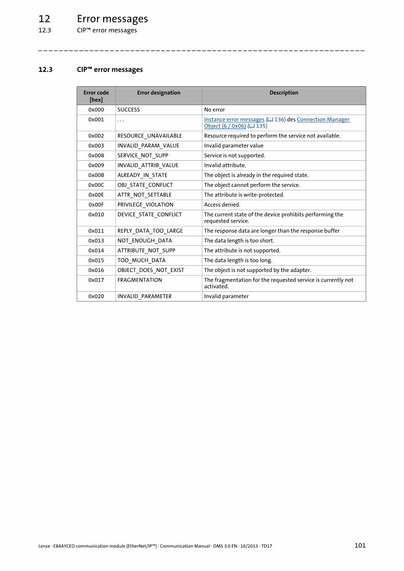
Lenze · E84AYCEO communication module (EtherNet/IP™) · Communication Manual · DMS 3.0 EN · 10/2013 · TD17 101
12 Error messages12.3 CIP™ error messages
_ _ _ _ _ _ _ _ _ _ _ _ _ _ _ _ _ _ _ _ _ _ _ _ _ _ _ _ _ _ _ _ _ _ _ _ _ _ _ _ _ _ _ _ _ _ _ _ _ _ _ _ _ _ _ _ _ _ _ _ _ _ _ _
12.3 CIP™ error messages
Error code[hex]
Error designation Description
0x000 SUCCESS No error
0x001 . . . Instance error messages ( 136) des Connection Manager Object (6 / 0x06) ( 135)
0x002 RESOURCE_UNAVAILABLE Resource required to perform the service not available.
0x003 INVALID_PARAM_VALUE Invalid parameter value
0x008 SERVICE_NOT_SUPP Service is not supported.
0x009 INVALID_ATTRIB_VALUE Invalid attribute.
0x00B ALREADY_IN_STATE The object is already in the required state.
0x00C OBJ_STATE_CONFLICT The object cannot perform the service.
0x00E ATTR_NOT_SETTABLE The attribute is write-protected.
0x00F PRIVILEGE_VIOLATION Access denied.
0x010 DEVICE_STATE_CONFLICT The current state of the device prohibits performing the requested service.
0x011 REPLY_DATA_TOO_LARGE The response data are longer than the response buffer
0x013 NOT_ENOUGH_DATA The data length is too short.
0x014 ATTRIBUTE_NOT_SUPP The attribute is not supported.
0x015 TOO_MUCH_DATA The data length is too long.
0x016 OBJECT_DOES_NOT_EXIST The object is not supported by the adapter.
0x017 FRAGMENTATION The fragmentation for the requested service is currently not activated.
0x020 INVALID_PARAMETER Invalid parameter

12 Error messages12.4 Mapping of Lenze device errors to DRIVECOM errors
102 Lenze · E84AYCEO communication module (EtherNet/IP™) · Communication Manual · DMS 3.0 EN · 10/2013 · TD17
_ _ _ _ _ _ _ _ _ _ _ _ _ _ _ _ _ _ _ _ _ _ _ _ _ _ _ _ _ _ _ _ _ _ _ _ _ _ _ _ _ _ _ _ _ _ _ _ _ _ _ _ _ _ _ _ _ _ _ _ _ _ _ _
12.4 Mapping of Lenze device errors to DRIVECOM errors
Via the instance attribute "FaultCode" of the Control Supervisor Object (41 / 0x29) ( 150) Lenzedevice errors are output with the DRIVECOM error numbers.
From inverter drive version V13.00 and communication module version V01.02 onwards, "CANEmergency Error Codes" are output as DRIVECOM error numbers!
The following tables show the assignment of the Lenze device errors and "CAN Emergency ErrorCodes" to the DRIVECOM errors.
Software manual/»Engineer« online help for Inverter Drive 8400
Here you will find detailed information about the Lenze error messages listed in the following table.
Lenze error CAN DRIVECOM error
Error number[32 bits]
Error message Emergency Error Code
Error number[hex]
Error message
xx.0111.00002 Su02: One mains phase is missing 0x3000 0x3000 Voltage
xx.0111.00003 Su03: Too frequent mains switching 0x3000 0x3000 Voltage
xx.0111.00004 Su04: CU insufficiently supplied 0x3000 0x3000 Voltage
xx.0111.00006 Su06: Power input overload 0x3000 0x3000 Voltage
xx.0119.00000 OH4: Heat sink temp. > Switch-off temp. -5°C 0x4000 0x4000 Temperature
xx.0119.00001 OH1: Heatsink overtemperature 0x4000 0x4000 Temperature
xx.0119.00002 OH7: Motor temperature resolver > C121 0x4000 0x4000 Temperature
xx.0119.00003 OH9: Motor overtemperature resolver 0x4000 0x4000 Temperature
xx.0119.00012 Sd6: Error temperature sensor resolver 0x7300 0x7300 Sensor
xx.0119.00015 OH3: Motor temperature (X106) triggered 0x4000 0x4000 Temperature
xx.0119.00020 OH6: Motor temperature MultiEncoder > C121 0x4000 0x4000 Temperature
xx.0119.00021 OH12: Motor overtemperature MultiEncoder 0x4000 0x4000 Temperature
xx.0119.00022 Sd12: Error temperature sensor MultiEncoder 0x7300 0x7300 Sensor
xx.0119.00050 OC5: Ixt overload 0x2000 0x2000 Current
xx.0123.00001 OT1: Maximal torque reached 0x8300 0x8302 Torque limiting
xx.0123.00007 OC7: Motor overcurrent 0x2000 0x2000 Current
xx.0123.00014 OU: DC bus overvoltage 0x3100 0x3110 Mains overvoltage
xx.0123.00015 LU: DC bus undervoltage 0x3100 0x3120 Mains undervoltage
xx.0123.00016 OC1: Power section - short circuit 0x2000 0x2130 Short Circuit
xx.0123.00017 OC2: Power section - earth fault 0x2000 0x2120 Short to Earth
xx.0123.00024 Sd2: Wire breakage resolver 0x7300 0x7303 Resolver 1 defective
xx.0123.00026 Sd7: Error encoder communication 0x7300 0x7305 Incremental encoder 1 defective
xx.0123.00027 Sd4: Wire breakage MultiEncoder 0x7300 0x7300 Sensor
xx.0123.00030 OC10: Maximum current reached 0x2000 0x2000 Current
xx.0123.00031 OC17: Clamp sets pulse inhibit 0xF000 0xF000 Additional functions
xx.0123.00032 OS1: Maximum speed limit reached 0x8400 0x8402 Velocity Limiting
xx.0123.00033 OS2: Max. motor speed 0x8400 0x8400 Speed Controller
xx.0123.00056 ID2: Motor data identification error 0xF000 0xF000 Additional functions
xx.0123.00057 ID1: Motor data identification error 0xF000 0xF000 Additional functions
xx.0123.00058 ID3: CINH motor data identification 0xF000 0xF000 Additional functions
xx.0123.00059 ID4: Error resistor identification 0xF000 0xF000 Additional functions
xx.0123.00060 ID7: Motor control does not match motor data 0xF000 0xF000 Additional functions
xx.0123.00062 Sd8: Encoder angular drift monitoring 0x7300 0x7300 Sensor
xx.0123.00065 OC12: I2xt overload - brake resistor 0xF000 0x7110 Brake Chopper

Lenze · E84AYCEO communication module (EtherNet/IP™) · Communication Manual · DMS 3.0 EN · 10/2013 · TD17 103
12 Error messages12.4 Mapping of Lenze device errors to DRIVECOM errors
_ _ _ _ _ _ _ _ _ _ _ _ _ _ _ _ _ _ _ _ _ _ _ _ _ _ _ _ _ _ _ _ _ _ _ _ _ _ _ _ _ _ _ _ _ _ _ _ _ _ _ _ _ _ _ _ _ _ _ _ _ _ _ _
xx.0123.00071 OC11: Current clamp for too long (>1 sec) 0xF000 0xF000 Additional functions
xx.0123.00074 ID5: Error pole position identification 0xF000 0xF000 Additional functions
xx.0123.00075 ID6: Error resolver ident. 0xF000 0xF000 Additional functions
xx.0123.00090 OC13: Maximum current for Fch exceeded 0x2000 0x2000 Current
xx.0123.00093 OT2: Speed controller output is limited 0xF000 0x7310 Speed
xx.0123.00094 FC01: Switching frequency reduction 0x2000 0xF000 Additional functions
xx.0123.00095 FC02: Maximum speed for Fchop 0xF000 0xF000 Additional functions
xx.0123.00096 OC14: Limitation direct-axis current controller 0xF000 0xF000 Additional functions
xx.0123.00097 OC15: Limitation cross current controller 0xF000 0xF000 Additional functions
xx.0123.00098 OC16: Limitation torque controller 0xF000 0xF000 Additional functions
xx.0123.00099 FC03: Limitation field controller 0xF000 0xF000 Additional functions
xx.0123.00105 OC6: I2xt overload - motor 0x2000 0x7120 Motor
xx.0123.00145 LP1: Motor phase failure 0x3000 0x3130 Phase Failure
xx.0123.00200 SD10: Speed limit - feedback system 12 0x7300 0x7300 Sensor
xx.0123.00201 SD11: Speed limit - feedback system 67 0x7300 0x7300 Sensor
xx.0123.00205 SD3: Open circuit - feedback system 0x7300 0x7301 Tacho defective
xx.0125.00001 An01: AIN1_I < 4 mA 0xF000 0xF000 Additional functions
xx.0125.00002 An02: AIN2_I < 4 mA 0xF000 0xF000 Additional functions
xx.0126.00001 Ab01: Axis bus timeout 0x8000 0x8000 Monitoring
xx.0126.00002 Ab02: Axis bus IO error 0x8100 0x8100 Communication
xx.0127.00002 CE04: MCI communication error 0x7000 0x7500 Communication
xx.0127.00015 CE0F: MCI control word 0xF000 0xF000 Additional functions
xx.0131.00000 CE4: CAN Bus Off 0x8000 0x8000 Monitoring
xx.0131.00006 CA06: CAN CRC error 0x8000 0x8000 Monitoring
xx.0131.00007 CA07: CAN Bus Warn 0x8000 0x8000 Monitoring
xx.0131.00008 CA08: CAN Bus Stopped 0x8000 0x8000 Monitoring
xx.0131.00011 CA0b: CAN HeartBeatEvent 0x8130 0x8000 Monitoring
xx.0131.00015 CA0F: CAN control word 0xF000 0x8000 Monitoring
xx.0135.00001 CE1: CAN RPDO1 0x8100 0x8100 Communication
xx.0135.00002 CE2: CAN RPDO2 0x8100 0x8100 Communication
xx.0135.00003 CE3: CAN RPDO3 0x8100 0x8100 Communication
xx.0135.00004 CP04: CAN RPDO4 0x8100 0x8100 Communication
xx.0140.00013 CI01: Module missing/incompatible 0x7000 0x7000 Additional Modules
xx.0144.00001 PS01: No memory module 0x6300 0x6300 Date Set
xx.0144.00002 PS02: Par. set invalid 0x6300 0x6300 Date Set
xx.0144.00003 PS03: Par. set device invalid 0x6300 0x6300 Date Set
xx.0144.00004 PS04: Par. set device incompatible 0x6300 0x6300 Date Set
xx.0144.00007 PS07: Par. mem. module invalid 0x6300 0x6300 Date Set
xx.0144.00008 PS08: Par. device invalid 0x6300 0x6300 Date Set
xx.0144.00009 PS09: Par. format invalid 0x6300 0x6300 Date Set
xx.0144.00010 PS10: Memory module link invalid 0x5000 0x5000 Device Hardware
xx.0144.00031 PS31: Ident. error 0x6300 0x6300 Date Set
xx.0145.00014 dF14: SW-HW invalid 0x5530 0x6000 Device software
xx.0145.00015 dF15: DCCOM CU2 error 0x6100 0x6100 Internal software
xx.0145.00024 dF18: BU RCOM error 0x6100 0x6100 Internal software
xx.0145.00025 dF25: CU RCOM error 0x6100 0x6100 Internal software
xx.0145.00026 dF26: Appl. watchdog 0x6200 0x6010 Software reset (watchdog)
xx.0145.00033 dF21: BU watchdog 0x6100 0x6010 Software reset (watchdog)
xx.0145.00034 dF22: CU Watchdog 0x6100 0x6010 Software reset (watchdog)
xx.0145.00035 dF10: AutoTrip reset 0xF000 0xF000 Additional functions
Lenze error CAN DRIVECOM error
Error number[32 bits]
Error message Emergency Error Code
Error number[hex]
Error message
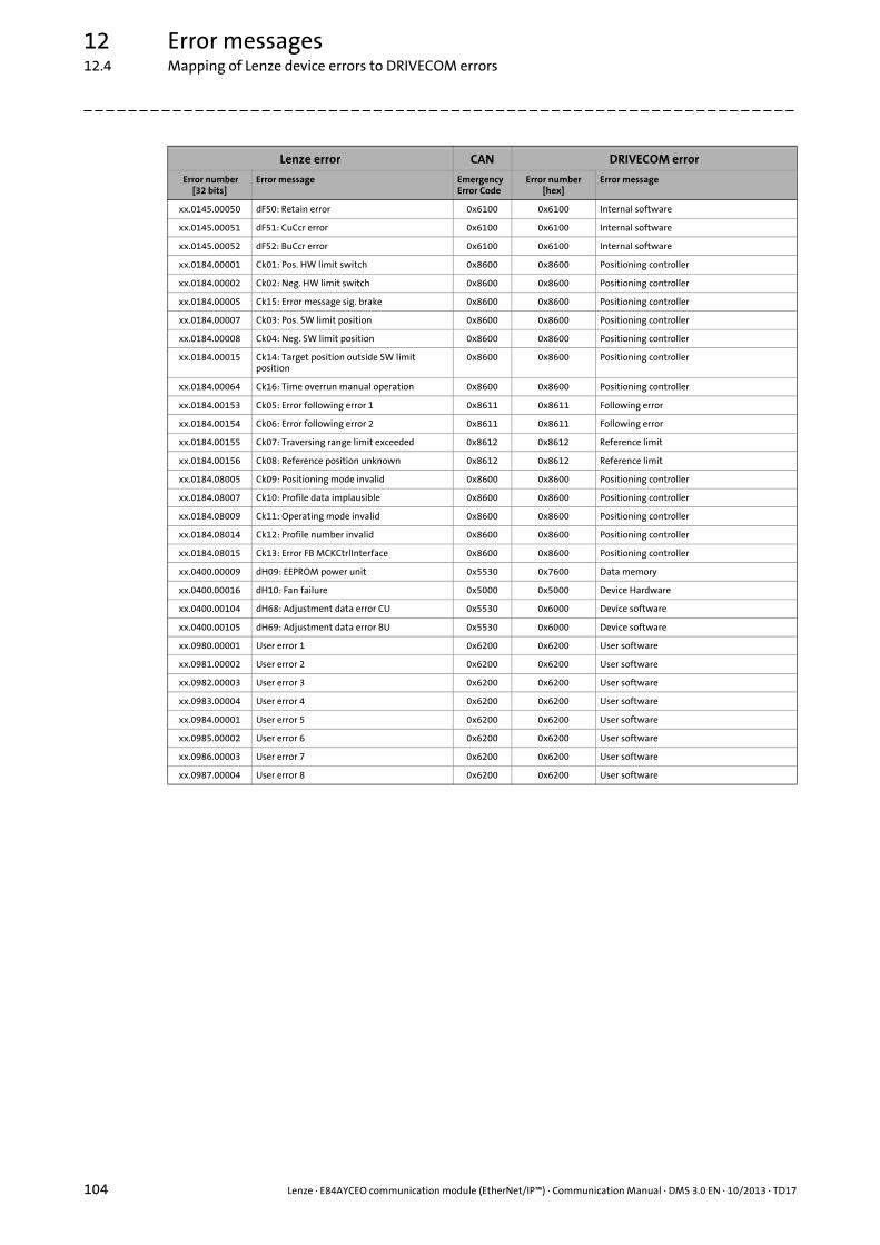
12 Error messages12.4 Mapping of Lenze device errors to DRIVECOM errors
104 Lenze · E84AYCEO communication module (EtherNet/IP™) · Communication Manual · DMS 3.0 EN · 10/2013 · TD17
_ _ _ _ _ _ _ _ _ _ _ _ _ _ _ _ _ _ _ _ _ _ _ _ _ _ _ _ _ _ _ _ _ _ _ _ _ _ _ _ _ _ _ _ _ _ _ _ _ _ _ _ _ _ _ _ _ _ _ _ _ _ _ _
xx.0145.00050 dF50: Retain error 0x6100 0x6100 Internal software
xx.0145.00051 dF51: CuCcr error 0x6100 0x6100 Internal software
xx.0145.00052 dF52: BuCcr error 0x6100 0x6100 Internal software
xx.0184.00001 Ck01: Pos. HW limit switch 0x8600 0x8600 Positioning controller
xx.0184.00002 Ck02: Neg. HW limit switch 0x8600 0x8600 Positioning controller
xx.0184.00005 Ck15: Error message sig. brake 0x8600 0x8600 Positioning controller
xx.0184.00007 Ck03: Pos. SW limit position 0x8600 0x8600 Positioning controller
xx.0184.00008 Ck04: Neg. SW limit position 0x8600 0x8600 Positioning controller
xx.0184.00015 Ck14: Target position outside SW limit position
0x8600 0x8600 Positioning controller
xx.0184.00064 Ck16: Time overrun manual operation 0x8600 0x8600 Positioning controller
xx.0184.00153 Ck05: Error following error 1 0x8611 0x8611 Following error
xx.0184.00154 Ck06: Error following error 2 0x8611 0x8611 Following error
xx.0184.00155 Ck07: Traversing range limit exceeded 0x8612 0x8612 Reference limit
xx.0184.00156 Ck08: Reference position unknown 0x8612 0x8612 Reference limit
xx.0184.08005 Ck09: Positioning mode invalid 0x8600 0x8600 Positioning controller
xx.0184.08007 Ck10: Profile data implausible 0x8600 0x8600 Positioning controller
xx.0184.08009 Ck11: Operating mode invalid 0x8600 0x8600 Positioning controller
xx.0184.08014 Ck12: Profile number invalid 0x8600 0x8600 Positioning controller
xx.0184.08015 Ck13: Error FB MCKCtrlInterface 0x8600 0x8600 Positioning controller
xx.0400.00009 dH09: EEPROM power unit 0x5530 0x7600 Data memory
xx.0400.00016 dH10: Fan failure 0x5000 0x5000 Device Hardware
xx.0400.00104 dH68: Adjustment data error CU 0x5530 0x6000 Device software
xx.0400.00105 dH69: Adjustment data error BU 0x5530 0x6000 Device software
xx.0980.00001 User error 1 0x6200 0x6200 User software
xx.0981.00002 User error 2 0x6200 0x6200 User software
xx.0982.00003 User error 3 0x6200 0x6200 User software
xx.0983.00004 User error 4 0x6200 0x6200 User software
xx.0984.00001 User error 5 0x6200 0x6200 User software
xx.0985.00002 User error 6 0x6200 0x6200 User software
xx.0986.00003 User error 7 0x6200 0x6200 User software
xx.0987.00004 User error 8 0x6200 0x6200 User software
Lenze error CAN DRIVECOM error
Error number[32 bits]
Error message Emergency Error Code
Error number[hex]
Error message

Lenze · E84AYCEO communication module (EtherNet/IP™) · Communication Manual · DMS 3.0 EN · 10/2013 · TD17 105
12 Error messages12.4 Mapping of Lenze device errors to DRIVECOM errors
_ _ _ _ _ _ _ _ _ _ _ _ _ _ _ _ _ _ _ _ _ _ _ _ _ _ _ _ _ _ _ _ _ _ _ _ _ _ _ _ _ _ _ _ _ _ _ _ _ _ _ _ _ _ _ _ _ _ _ _ _ _ _ _
EtherNet/IP error messages
Lenze error DRIVECOM error
Error number[32 bits]
Error message Error number[hex]
Error message
xx.0444.12544 EtherNet/IP: Exist. connect. to 8400 lost 0x7510 Serial Interface No 1
xx.0444.21809 EtherNet/IP: Memory: No Access 0x7600 Data memory
xx.0444.21810 EtherNet/IP: Memory: Read Error 0x7600 Data memory
xx.0444.21811 EtherNet/IP: Memory: Write Error 0x7600 Data memory
xx.0444.24592 EtherNet/IP: Restart by Watchdogreset 0x6010 Software reset (watchdog)
xx.0444.24593 EtherNet/IP: Internal Error 0x6100 Internal software
xx.0444.24832 EtherNet/IP: Internal Error 0x6100 Internal software
xx.0444.24833 EtherNet/IP: Internal Error 0x6100 Internal software
xx.0444.25631 EtherNet/IP: Invalid Parameter Set 0x7421 Invalid Parameters
xx.0444.25632 EtherNet/IP: Error: Lenze Setting Loaded 0x7421 Invalid Parameters
xx.0444.25648 EtherNet/IP: Invalid Configuration 0x7421 Invalid Parameters
xx.0444.25907 EtherNet/IP: Invalid IP Parameter 0x7421 Invalid Parameters
xx.0444.33041 EtherNet/IP: Fault Mode 0x7000 Additional Modules
xx.0444.33042 EtherNet/IP: Explicit Message Timeout 0x7500 Communication
xx.0444.33044 EtherNet/IP: Overall Ethernet Timeout 0x7500 Communication
xx.0444.33057 EtherNet/IP: Ethernet cable pulled out 0x9000 External malfunction
xx.0444.33074 EtherNet/IP: Idle Mode 0x7000 Additional Modules
xx.0444.33395 EtherNet/IP: Duplicate IP Address 0x7421 Invalid Parameters

13 Parameter reference13.1 Parameters of the communication module
106 Lenze · E84AYCEO communication module (EtherNet/IP™) · Communication Manual · DMS 3.0 EN · 10/2013 · TD17
_ _ _ _ _ _ _ _ _ _ _ _ _ _ _ _ _ _ _ _ _ _ _ _ _ _ _ _ _ _ _ _ _ _ _ _ _ _ _ _ _ _ _ _ _ _ _ _ _ _ _ _ _ _ _ _ _ _ _ _ _ _ _ _
13 Parameter reference
This chapter supplements the parameter list and the table of attributes for the Inverter Drive 8400contained in the software manual and in the »Engineer« online help by the parameters of thecommunication module E84AYCEO (EtherNet/IP).
13.1 Parameters of the communication module
This chapter lists the parameters of the E84AYCEO communication module (EtherNet/IP) innumerically ascending order.
C13000
C13001
Software manual/»Engineer« online help for Inverter Drives 8400
Here you will find general information on parameters.
Parameter | Name:
C13000 | IP AddressData type: UNSIGNED_8
Index: 11575 = 0x2D37
Setting of the IP addressSetting the IP configuration of the Inverter Drive 8400 ( 42)
Setting range (min. value | unit | max. value)
0 255
Subcodes Lenze setting Info
C13000/1 192 IP address (most significant byte)
C13000/2 168 IP address
C13000/3 124 IP address
C13000/4 16 IP address (least significant byte)
Read access Write access CINH PLC STOP No transfer PDO_MAP_RX PDO_MAP_TX COM MOT
Parameter | Name:
C13001 | Subnetwork MaskData type: UNSIGNED_8
Index: 11574 = 0x2D36
Setting of the subnet maskSetting the IP configuration of the Inverter Drive 8400 ( 42)
Setting range (min. value | unit | max. value)
0 255
Subcodes Lenze setting Info
C13001/1 255 Subnet mask (most significant byte)
C13001/2 255 Subnet mask
C13001/3 255 Subnet mask
C13001/4 0 Subnet mask (least significant byte)
Read access Write access CINH PLC STOP No transfer PDO_MAP_RX PDO_MAP_TX COM MOT
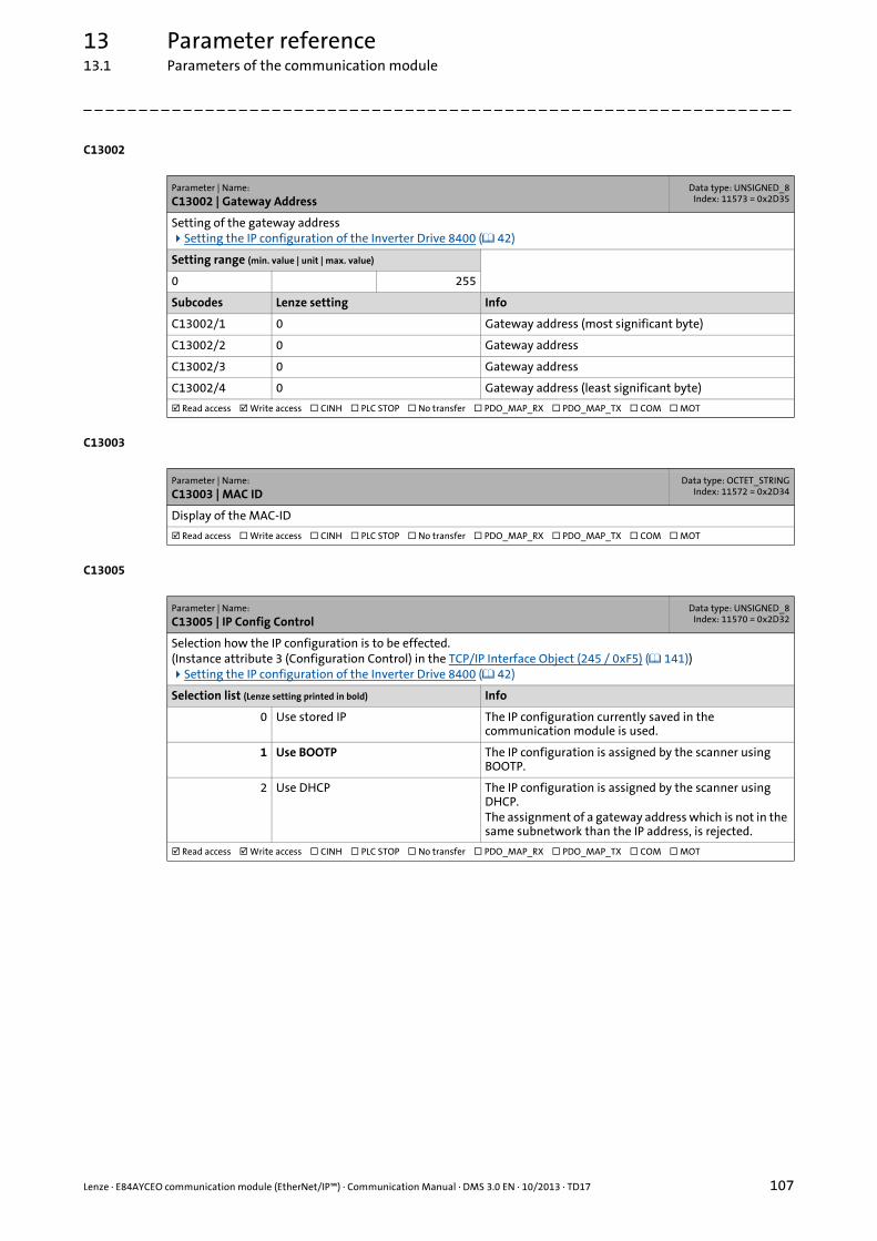
Lenze · E84AYCEO communication module (EtherNet/IP™) · Communication Manual · DMS 3.0 EN · 10/2013 · TD17 107
13 Parameter reference13.1 Parameters of the communication module
_ _ _ _ _ _ _ _ _ _ _ _ _ _ _ _ _ _ _ _ _ _ _ _ _ _ _ _ _ _ _ _ _ _ _ _ _ _ _ _ _ _ _ _ _ _ _ _ _ _ _ _ _ _ _ _ _ _ _ _ _ _ _ _
C13002
C13003
C13005
Parameter | Name:
C13002 | Gateway AddressData type: UNSIGNED_8
Index: 11573 = 0x2D35
Setting of the gateway addressSetting the IP configuration of the Inverter Drive 8400 ( 42)
Setting range (min. value | unit | max. value)
0 255
Subcodes Lenze setting Info
C13002/1 0 Gateway address (most significant byte)
C13002/2 0 Gateway address
C13002/3 0 Gateway address
C13002/4 0 Gateway address (least significant byte)
Read access Write access CINH PLC STOP No transfer PDO_MAP_RX PDO_MAP_TX COM MOT
Parameter | Name:
C13003 | MAC IDData type: OCTET_STRING
Index: 11572 = 0x2D34
Display of the MAC-ID
Read access Write access CINH PLC STOP No transfer PDO_MAP_RX PDO_MAP_TX COM MOT
Parameter | Name:
C13005 | IP Config ControlData type: UNSIGNED_8
Index: 11570 = 0x2D32
Selection how the IP configuration is to be effected.(Instance attribute 3 (Configuration Control) in the TCP/IP Interface Object (245 / 0xF5) ( 141))Setting the IP configuration of the Inverter Drive 8400 ( 42)
Selection list (Lenze setting printed in bold) Info
0 Use stored IP The IP configuration currently saved in the communication module is used.
1 Use BOOTP The IP configuration is assigned by the scanner using BOOTP.
2 Use DHCP The IP configuration is assigned by the scanner using DHCP.The assignment of a gateway address which is not in the same subnetwork than the IP address, is rejected.
Read access Write access CINH PLC STOP No transfer PDO_MAP_RX PDO_MAP_TX COM MOT

13 Parameter reference13.1 Parameters of the communication module
108 Lenze · E84AYCEO communication module (EtherNet/IP™) · Communication Manual · DMS 3.0 EN · 10/2013 · TD17
_ _ _ _ _ _ _ _ _ _ _ _ _ _ _ _ _ _ _ _ _ _ _ _ _ _ _ _ _ _ _ _ _ _ _ _ _ _ _ _ _ _ _ _ _ _ _ _ _ _ _ _ _ _ _ _ _ _ _ _ _ _ _ _
C13006
C13010
C13011
Parameter | Name:
C13006 | Multicast IP Start AddressData type: UNSIGNED_8
Index: 11569 = 0x2D31
Setting of the multicast IP addressSetting the IP configuration of the Inverter Drive 8400 ( 42)
Setting range (min. value | unit | max. value)
0 255
Subcodes Lenze setting Info
C13006/1 239 Multicast IP start address (most significant byte)
C13006/2 64 Multicast IP start address
C13006/3 2 Multicast IP start address
C13006/4 224 Multicast start address (least significant byte)
Read access Write access CINH PLC STOP No transfer PDO_MAP_RX PDO_MAP_TX COM MOT
Parameter | Name:
C13010 | Active IP AddressData type: UNSIGNED_8Index: 11565 = 0x2D2D
Display of the active IP address(Instance attribute 5 (IP Address) in the TCP/IP Interface Object (245 / 0xF5) ( 141))
Display range (min. value | unit | max. value)
0 255
Subcodes Info
C13010/1 Active IP address (most significant byte)
C13010/2 Active IP Address
C13010/3 Active IP Address
C13010/4 Active IP address (least significant byte)
Read access Write access CINH PLC STOP No transfer PDO_MAP_RX PDO_MAP_TX COM MOT
Parameter | Name:
C13011 | Active Subnetwork MaskData type: UNSIGNED_8
Index: 11564 = 0x2D2C
Display of the active subnetwork mask(Instance attribute 5 (IP Network Mask) in the TCP/IP Interface Object (245 / 0xF5) ( 141))
Display range (min. value | unit | max. value)
0 255
Subcodes Info
C13011/1 Active subnet mask (most significant byte)
C13011/2 Active Subnetwork Mask
C13011/3 Active Subnetwork Mask
C13011/4 Active subnet mask (least significant byte)
Read access Write access CINH PLC STOP No transfer PDO_MAP_RX PDO_MAP_TX COM MOT
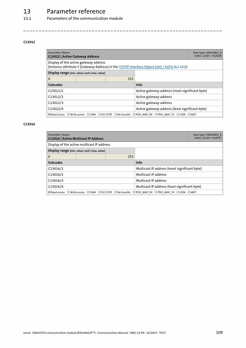
Lenze · E84AYCEO communication module (EtherNet/IP™) · Communication Manual · DMS 3.0 EN · 10/2013 · TD17 109
13 Parameter reference13.1 Parameters of the communication module
_ _ _ _ _ _ _ _ _ _ _ _ _ _ _ _ _ _ _ _ _ _ _ _ _ _ _ _ _ _ _ _ _ _ _ _ _ _ _ _ _ _ _ _ _ _ _ _ _ _ _ _ _ _ _ _ _ _ _ _ _ _ _ _
C13012
C13016
Parameter | Name:
C13012 | Active Gateway AddressData type: UNSIGNED_8
Index: 11563 = 0x2D2B
Display of the active gateway address(Instance attribute 5 (Gateway Address) in the TCP/IP Interface Object (245 / 0xF5) ( 141))
Display range (min. value | unit | max. value)
0 255
Subcodes Info
C13012/1 Active gateway address (most significant byte)
C13012/2 Active gateway address
C13012/3 Active gateway address
C13012/4 Active gateway address (least significant byte)
Read access Write access CINH PLC STOP No transfer PDO_MAP_RX PDO_MAP_TX COM MOT
Parameter | Name:
C13016 | Active Multicast IP AddressData type: UNSIGNED_8
Index: 11559 = 0x2D27
Display of the active multicast IP address
Display range (min. value | unit | max. value)
0 255
Subcodes Info
C13016/1 Multicast IP address (most significant byte)
C13016/2 Multicast IP address
C13016/3 Multicast IP address
C13016/4 Multicast IP address (least significant byte)
Read access Write access CINH PLC STOP No transfer PDO_MAP_RX PDO_MAP_TX COM MOT

13 Parameter reference13.1 Parameters of the communication module
110 Lenze · E84AYCEO communication module (EtherNet/IP™) · Communication Manual · DMS 3.0 EN · 10/2013 · TD17
_ _ _ _ _ _ _ _ _ _ _ _ _ _ _ _ _ _ _ _ _ _ _ _ _ _ _ _ _ _ _ _ _ _ _ _ _ _ _ _ _ _ _ _ _ _ _ _ _ _ _ _ _ _ _ _ _ _ _ _ _ _ _ _
C13017
C13018
C13019
Parameter | Name:
C13017 | Ethernet Config ControlData type: UNSIGNED_16
Index: 11558 = 0x2D26
Setting of the baud rate for the Ethernet connectionsDependent on the configuration of the Ethernet port of the device to be connected, we recommend the use of a cross-over cable.EtherNet/IP connection ( 29)
Selection list
0 Auto-Negotiation
1 10 Mbps
2 100 Mbps
3 Reserved
4 Reserved
5 10 Mbps/Half Duplex
6 10 Mbps/Full Duplex
7 100 Mbps/Half Duplex
8 100 Mbps/Full Duplex
9 Reserved
10 Reserved
11 Reserved
12 Reserved
Subcodes Lenze setting Info
C13017/1 0: Auto-Negotiation Ethernet setting port X259
C13017/2 0: Auto-Negotiation Ethernet setting port X260
Read access Write access CINH PLC STOP No transfer PDO_MAP_RX PDO_MAP_TX COM MOT
Parameter | Name:
C13018 | Multicast Config Alloc ControlData type: UNSIGNED_8
Index: 11557 = 0x2D25
Selection for multicast IP addressing via instance attribute 9 (Mcast Config) in the TCP/IP Interface Object (245 / 0xF5) ( 141)
Selection list (Lenze setting printed in bold)
0 Default Allocation Algorithm
1 Multicast IP Start Address
Read access Write access CINH PLC STOP No transfer PDO_MAP_RX PDO_MAP_TX COM MOT
Parameter | Name:
C13019 | Multicast Config TTL ValueData type: UNSIGNED_8
Index: 11556 = 0x2D24
Setting of the multicast TTL value for the validity time of data packets in the EtherNet/IP network(Instance attribute 8 (TTL Value) in the TCP/IP Interface Object (245 / 0xF5) ( 141))
Setting range (min. value | unit | max. value) Lenze setting
1 255 1
Read access Write access CINH PLC STOP No transfer PDO_MAP_RX PDO_MAP_TX COM MOT
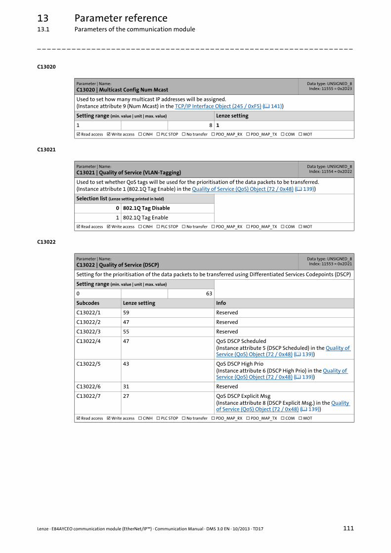
Lenze · E84AYCEO communication module (EtherNet/IP™) · Communication Manual · DMS 3.0 EN · 10/2013 · TD17 111
13 Parameter reference13.1 Parameters of the communication module
_ _ _ _ _ _ _ _ _ _ _ _ _ _ _ _ _ _ _ _ _ _ _ _ _ _ _ _ _ _ _ _ _ _ _ _ _ _ _ _ _ _ _ _ _ _ _ _ _ _ _ _ _ _ _ _ _ _ _ _ _ _ _ _
C13020
C13021
C13022
Parameter | Name:
C13020 | Multicast Config Num McastData type: UNSIGNED_8
Index: 11555 = 0x2D23
Used to set how many multicast IP addresses will be assigned.(Instance attribute 9 (Num Mcast) in the TCP/IP Interface Object (245 / 0xF5) ( 141))
Setting range (min. value | unit | max. value) Lenze setting
1 8 1
Read access Write access CINH PLC STOP No transfer PDO_MAP_RX PDO_MAP_TX COM MOT
Parameter | Name:
C13021 | Quality of Service (VLAN-Tagging)Data type: UNSIGNED_8
Index: 11554 = 0x2D22
Used to set whether QoS tags will be used for the prioritisation of the data packets to be transferred.(Instance attribute 1 (802.1Q Tag Enable) in the Quality of Service (QoS) Object (72 / 0x48) ( 139))
Selection list (Lenze setting printed in bold)
0 802.1Q Tag Disable
1 802.1Q Tag Enable
Read access Write access CINH PLC STOP No transfer PDO_MAP_RX PDO_MAP_TX COM MOT
Parameter | Name:
C13022 | Quality of Service (DSCP)Data type: UNSIGNED_8
Index: 11553 = 0x2D21
Setting for the prioritisation of the data packets to be transferred using Differentiated Services Codepoints (DSCP)
Setting range (min. value | unit | max. value)
0 63
Subcodes Lenze setting Info
C13022/1 59 Reserved
C13022/2 47 Reserved
C13022/3 55 Reserved
C13022/4 47 QoS DSCP Scheduled(Instance attribute 5 (DSCP Scheduled) in the Quality of Service (QoS) Object (72 / 0x48) ( 139))
C13022/5 43 QoS DSCP High Prio(Instance attribute 6 (DSCP High Prio) in the Quality of Service (QoS) Object (72 / 0x48) ( 139))
C13022/6 31 Reserved
C13022/7 27 QoS DSCP Explicit Msg(Instance attribute 8 (DSCP Explicit Msg.) in the Quality of Service (QoS) Object (72 / 0x48) ( 139))
Read access Write access CINH PLC STOP No transfer PDO_MAP_RX PDO_MAP_TX COM MOT
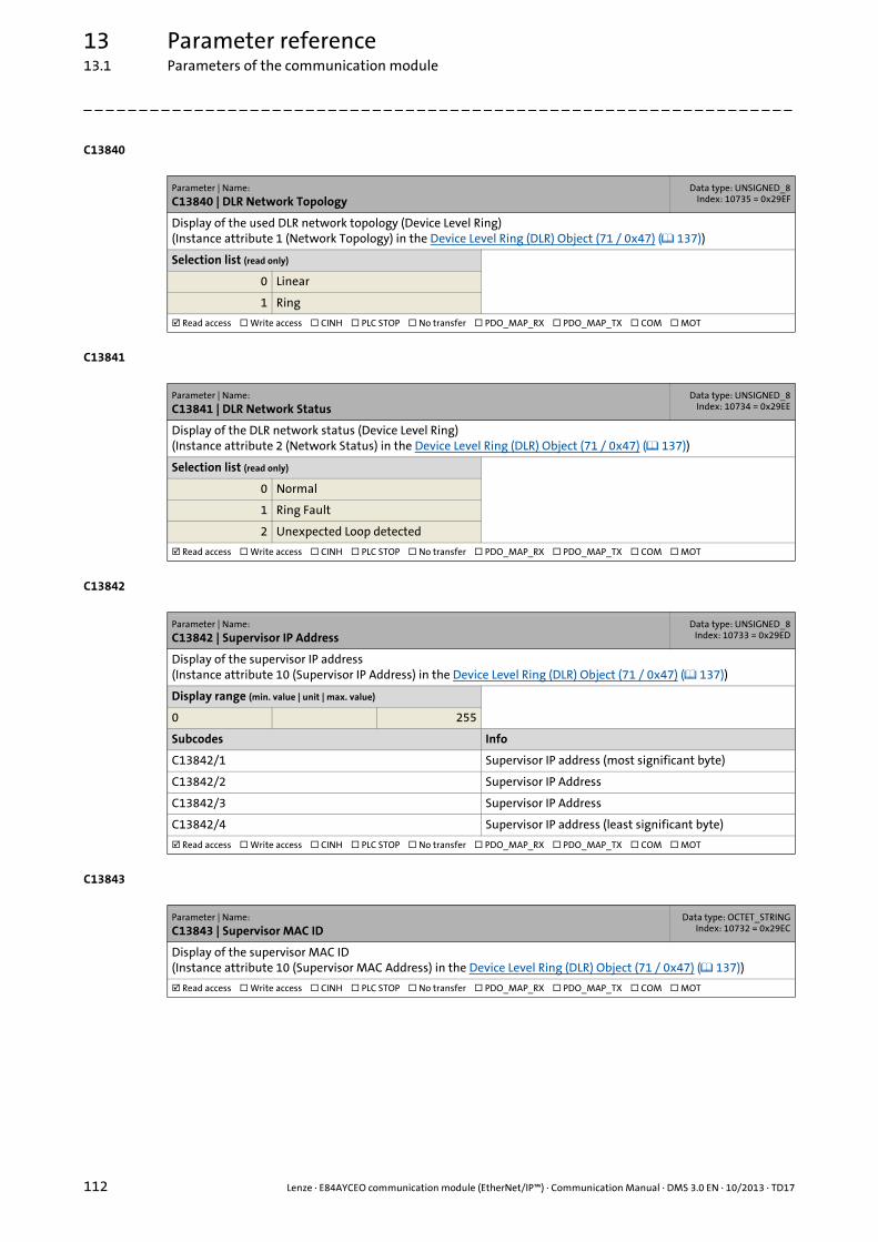
13 Parameter reference13.1 Parameters of the communication module
112 Lenze · E84AYCEO communication module (EtherNet/IP™) · Communication Manual · DMS 3.0 EN · 10/2013 · TD17
_ _ _ _ _ _ _ _ _ _ _ _ _ _ _ _ _ _ _ _ _ _ _ _ _ _ _ _ _ _ _ _ _ _ _ _ _ _ _ _ _ _ _ _ _ _ _ _ _ _ _ _ _ _ _ _ _ _ _ _ _ _ _ _
C13840
C13841
C13842
C13843
Parameter | Name:
C13840 | DLR Network TopologyData type: UNSIGNED_8
Index: 10735 = 0x29EF
Display of the used DLR network topology (Device Level Ring)(Instance attribute 1 (Network Topology) in the Device Level Ring (DLR) Object (71 / 0x47) ( 137))
Selection list (read only)
0 Linear
1 Ring
Read access Write access CINH PLC STOP No transfer PDO_MAP_RX PDO_MAP_TX COM MOT
Parameter | Name:
C13841 | DLR Network StatusData type: UNSIGNED_8
Index: 10734 = 0x29EE
Display of the DLR network status (Device Level Ring)(Instance attribute 2 (Network Status) in the Device Level Ring (DLR) Object (71 / 0x47) ( 137))
Selection list (read only)
0 Normal
1 Ring Fault
2 Unexpected Loop detected
Read access Write access CINH PLC STOP No transfer PDO_MAP_RX PDO_MAP_TX COM MOT
Parameter | Name:
C13842 | Supervisor IP AddressData type: UNSIGNED_8
Index: 10733 = 0x29ED
Display of the supervisor IP address(Instance attribute 10 (Supervisor IP Address) in the Device Level Ring (DLR) Object (71 / 0x47) ( 137))
Display range (min. value | unit | max. value)
0 255
Subcodes Info
C13842/1 Supervisor IP address (most significant byte)
C13842/2 Supervisor IP Address
C13842/3 Supervisor IP Address
C13842/4 Supervisor IP address (least significant byte)
Read access Write access CINH PLC STOP No transfer PDO_MAP_RX PDO_MAP_TX COM MOT
Parameter | Name:
C13843 | Supervisor MAC IDData type: OCTET_STRING
Index: 10732 = 0x29EC
Display of the supervisor MAC ID(Instance attribute 10 (Supervisor MAC Address) in the Device Level Ring (DLR) Object (71 / 0x47) ( 137))
Read access Write access CINH PLC STOP No transfer PDO_MAP_RX PDO_MAP_TX COM MOT

Lenze · E84AYCEO communication module (EtherNet/IP™) · Communication Manual · DMS 3.0 EN · 10/2013 · TD17 113
13 Parameter reference13.1 Parameters of the communication module
_ _ _ _ _ _ _ _ _ _ _ _ _ _ _ _ _ _ _ _ _ _ _ _ _ _ _ _ _ _ _ _ _ _ _ _ _ _ _ _ _ _ _ _ _ _ _ _ _ _ _ _ _ _ _ _ _ _ _ _ _ _ _ _
C13844
C13845
C13846
C13847
Parameter | Name:
C13844 | Beacon TimesData type: UNSIGNED_32
Index: 10731 = 0x29EB
Display of the beacon times (μs)
Subcodes Info
C13844/1 Beacon interval
C13844/2 Beacon timeout
Read access Write access CINH PLC STOP No transfer PDO_MAP_RX PDO_MAP_TX COM MOT
Parameter | Name:
C13845 | Beacon FramesData type: UNSIGNED_32
Index: 10730 = 0x29EA
Display of beacon frame information
Subcodes Info
C13845/1 Beacon frames - port X259
C13845/2 Beacon frame error - port X259
C13845/3 Beacon frames - port X260
C13845/4 Beacon frame error - port X260
Read access Write access CINH PLC STOP No transfer PDO_MAP_RX PDO_MAP_TX COM MOT
Parameter | Name:
C13846 | Address Conflict DetectionData type: UNSIGNED_8
Index: 10729 = 0x29E9
Activation of the address conflict detection (ACD)(Instance attribute 10 (SelectAcd) in the TCP/IP Interface Object (245 / 0xF5) ( 141))Changing this value requires a reset of the device ("power off/on" or "type 0 reset").
Selection list (Lenze setting printed in bold)
0 Deactivated
1 Enable
Read access Write access CINH PLC STOP No transfer PDO_MAP_RX PDO_MAP_TX COM MOT
Parameter | Name:
C13847 | Active Conflict Detection StateData type: UNSIGNED_8
Index: 10728 = 0x29E8
Display of the status of address conflict detection (ACD)
Selection list (read only)
0 Not conflicted
1 Conflicted
Read access Write access CINH PLC STOP No transfer PDO_MAP_RX PDO_MAP_TX COM MOT

13 Parameter reference13.1 Parameters of the communication module
114 Lenze · E84AYCEO communication module (EtherNet/IP™) · Communication Manual · DMS 3.0 EN · 10/2013 · TD17
_ _ _ _ _ _ _ _ _ _ _ _ _ _ _ _ _ _ _ _ _ _ _ _ _ _ _ _ _ _ _ _ _ _ _ _ _ _ _ _ _ _ _ _ _ _ _ _ _ _ _ _ _ _ _ _ _ _ _ _ _ _ _ _
C13848
C13849
C13850
Parameter | Name:
C13848 | Last Conflicted MAC IDData type: OCTET_STRING
Index: 10727 = 0x29E7
Display of the MAC address of the EtherNet/IP node with the last address conflict (ACD).The data of the last conflict will only be saved in this code if ACD is active at the moment when the conflict occurs (C13846 = 1).(Instance attribute 11 (RemoteMAC) in the TCP/IP Interface Object (245 / 0xF5) ( 141))
Read access Write access CINH PLC STOP No transfer PDO_MAP_RX PDO_MAP_TX COM MOT
Parameter | Name:
C13849 | Last Conflicted IP AddressData type: UNSIGNED_8
Index: 10726 = 0x29E6
Display of the MAC address of the EtherNet/IP node with the last address conflict (ACD).The data of the last conflict will only be saved in this code if ACD is active at the moment when the conflict occurs (C13846 = 1).
Display range (min. value | unit | max. value)
0 255
Subcodes Info
C13849/1 Last conflicted IP address (most significant byte)
C13849/2 Last conflicted IP address
C13849/3 Last conflicted IP address
C13849/4 Last conflicted IP address (least significant byte)
Read access Write access CINH PLC STOP No transfer PDO_MAP_RX PDO_MAP_TX COM MOT
Parameter | Name:
C13850 | All words to scannerData type: INTEGER_16Index: 10725 = 0x29E5
Display of the I/O data words transferred from the communication module (adapter) to the scanner.In the subcodes, all I/O data words transferred to the scanner are displayed. However, only the configured I/O data words are valid.
Display range (min. value | unit | max. value)
-32768 32767
Subcodes Info
C13850/1
...
C13850/16
Read access Write access CINH PLC STOP No transfer PDO_MAP_RX PDO_MAP_TX COM MOT

Lenze · E84AYCEO communication module (EtherNet/IP™) · Communication Manual · DMS 3.0 EN · 10/2013 · TD17 115
13 Parameter reference13.1 Parameters of the communication module
_ _ _ _ _ _ _ _ _ _ _ _ _ _ _ _ _ _ _ _ _ _ _ _ _ _ _ _ _ _ _ _ _ _ _ _ _ _ _ _ _ _ _ _ _ _ _ _ _ _ _ _ _ _ _ _ _ _ _ _ _ _ _ _
C13851
C13852
C13853
Parameter | Name:
C13851 | All words from scannerData type: INTEGER_16Index: 10724 = 0x29E4
Display of the I/O data words transferred from the scanner to the communication module (adapter).In the subcodes, all I/O data words transferred from the scanner are displayed. However, only the configured I/O data words are valid.
Display range (min. value | unit | max. value)
-32768 32767
Subcodes Info
C13851/1
...
C13851/16
Read access Write access CINH PLC STOP No transfer PDO_MAP_RX PDO_MAP_TX COM MOT
Parameter | Name:
C13852 | All words to the basic deviceData type: INTEGER_16Index: 10723 = 0x29E3
Display of the I/O data words transferred from the scanner to the communication module (adapter).In the subcodes, all I/O data words transferred from the scanner are displayed. However, only the configured I/O data words are valid.
Display range (min. value | unit | max. value)
-32768 32767
Subcodes Info
C13852/1
...
C13852/16
Read access Write access CINH PLC STOP No transfer PDO_MAP_RX PDO_MAP_TX COM MOT
Parameter | Name:
C13853 | All words to the basic deviceData type: INTEGER_16Index: 10722 = 0x29E2
Display of the I/O data words transferred from the communication module (adapter) to the scanner.In the subcodes, all I/O data words transferred to the scanner are displayed. However, only the configured I/O data words are valid.
Display range (min. value | unit | max. value)
-32768 32767
Subcodes Info
C13853/1
...
C13853/16
Read access Write access CINH PLC STOP No transfer PDO_MAP_RX PDO_MAP_TX COM MOT
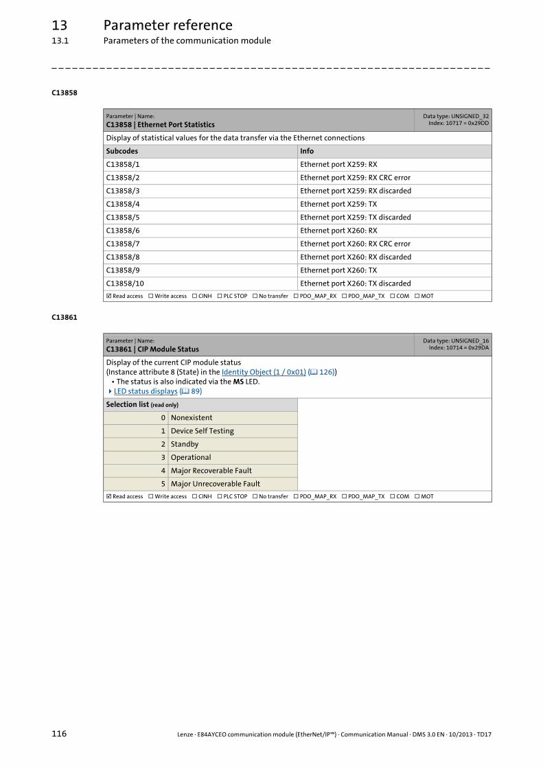
13 Parameter reference13.1 Parameters of the communication module
116 Lenze · E84AYCEO communication module (EtherNet/IP™) · Communication Manual · DMS 3.0 EN · 10/2013 · TD17
_ _ _ _ _ _ _ _ _ _ _ _ _ _ _ _ _ _ _ _ _ _ _ _ _ _ _ _ _ _ _ _ _ _ _ _ _ _ _ _ _ _ _ _ _ _ _ _ _ _ _ _ _ _ _ _ _ _ _ _ _ _ _ _
C13858
C13861
Parameter | Name:
C13858 | Ethernet Port StatisticsData type: UNSIGNED_32
Index: 10717 = 0x29DD
Display of statistical values for the data transfer via the Ethernet connections
Subcodes Info
C13858/1 Ethernet port X259: RX
C13858/2 Ethernet port X259: RX CRC error
C13858/3 Ethernet port X259: RX discarded
C13858/4 Ethernet port X259: TX
C13858/5 Ethernet port X259: TX discarded
C13858/6 Ethernet port X260: RX
C13858/7 Ethernet port X260: RX CRC error
C13858/8 Ethernet port X260: RX discarded
C13858/9 Ethernet port X260: TX
C13858/10 Ethernet port X260: TX discarded
Read access Write access CINH PLC STOP No transfer PDO_MAP_RX PDO_MAP_TX COM MOT
Parameter | Name:
C13861 | CIP Module StatusData type: UNSIGNED_16
Index: 10714 = 0x29DA
Display of the current CIP module status(Instance attribute 8 (State) in the Identity Object (1 / 0x01) ( 126))
• The status is also indicated via the MS LED.LED status displays ( 89)
Selection list (read only)
0 Nonexistent
1 Device Self Testing
2 Standby
3 Operational
4 Major Recoverable Fault
5 Major Unrecoverable Fault
Read access Write access CINH PLC STOP No transfer PDO_MAP_RX PDO_MAP_TX COM MOT

Lenze · E84AYCEO communication module (EtherNet/IP™) · Communication Manual · DMS 3.0 EN · 10/2013 · TD17 117
13 Parameter reference13.1 Parameters of the communication module
_ _ _ _ _ _ _ _ _ _ _ _ _ _ _ _ _ _ _ _ _ _ _ _ _ _ _ _ _ _ _ _ _ _ _ _ _ _ _ _ _ _ _ _ _ _ _ _ _ _ _ _ _ _ _ _ _ _ _ _ _ _ _ _
C13862
C13863
C13870
Parameter | Name:
C13862 | CIP Network StatusData type: UNSIGNED_16
Index: 10713 = 0x29D9
Display of the current CIP network status• The status is also indicated via the NS LED.LED status displays ( 89)
Selection list (read only)
0 No IP Address
1 Nonexistent
2 Established
3 Timed Out
4 Duplicate IP
5 Self-Test
Read access Write access CINH PLC STOP No transfer PDO_MAP_RX PDO_MAP_TX COM MOT
Parameter | Name:
C13863 | Ethernet PortData type: UNSIGNED_16
Index: 10712 = 0x29D8
Display of the baud rate currently used on the Ethernet connections
Selection list (read only)
0 Nonexistent
1 10 Mbps/Half Duplex
2 10 Mbps/Full Duplex
3 100 Mbps/Half Duplex
4 100 Mbps/Full Duplex
5 Reserved
6 Reserved
Subcodes Info
C13863/1 Ethernet port X259 link state
C13863/2 Ethernet port X260 link state
Read access Write access CINH PLC STOP No transfer PDO_MAP_RX PDO_MAP_TX COM MOT
Parameter | Name:
C13870 | CIP Connections StateData type: UNSIGNED_16
Index: 10705 = 0x29D1
Display of the current CIP connection status
Selection list (read only)
0 Nonexistent
3 Established
4 Timed Out
Subcodes Info
C13870/1 Status of CIP connection 1
... ...
C13870/8 Status of CIP connection 8
Read access Write access CINH PLC STOP No transfer PDO_MAP_RX PDO_MAP_TX COM MOT

13 Parameter reference13.1 Parameters of the communication module
118 Lenze · E84AYCEO communication module (EtherNet/IP™) · Communication Manual · DMS 3.0 EN · 10/2013 · TD17
_ _ _ _ _ _ _ _ _ _ _ _ _ _ _ _ _ _ _ _ _ _ _ _ _ _ _ _ _ _ _ _ _ _ _ _ _ _ _ _ _ _ _ _ _ _ _ _ _ _ _ _ _ _ _ _ _ _ _ _ _ _ _ _
C13871
C13872
C13873
Parameter | Name:
C13871 | CIP Connections TypeData type: UNSIGNED_16
Index: 10704 = 0x29D0
Display of the current CIP connection types• "Listen Only" connections are not displayed.
Selection list (read only)
0 Nonexistent
1 Exclusive Owner
2 Input Only
3 Listen Only
4 Explicit Connection
Subcodes Info
C13871/1 Type of CIP connection 1
... ...
C13871/8 Type of CIP connection 8
Read access Write access CINH PLC STOP No transfer PDO_MAP_RX PDO_MAP_TX COM MOT
Parameter | Name:
C13872 | CIP Connection TriggersData type: UNSIGNED_16
Index: 10703 = 0x29CF
Display of the current CIP connection class
Selection list (read only)
0 Nonexistent
1 Class 1, Cyclic, Client
163 Class 3, App. Obj., Server
Subcodes Info
C13872/1 Trigger of CIP connection 1
... ...
C13872/8 Trigger of CIP connection 8
Read access Write access CINH PLC STOP No transfer PDO_MAP_RX PDO_MAP_TX COM MOT
Parameter | Name:
C13873 | CIP Connections RPIData type: UNSIGNED_32
Index: 10702 = 0x29CE
Display of the RPI times (Requested Package Interval) currently used for the CIP connections ("Originator to Target" time)
Display range (min. value | unit | max. value)
0 ms 4294967295
Subcodes Info
C13873/1 RPI of CIP connection 1
... ...
C13873/8 RPI of CIP connection 8
Read access Write access CINH PLC STOP No transfer PDO_MAP_RX PDO_MAP_TX COM MOT
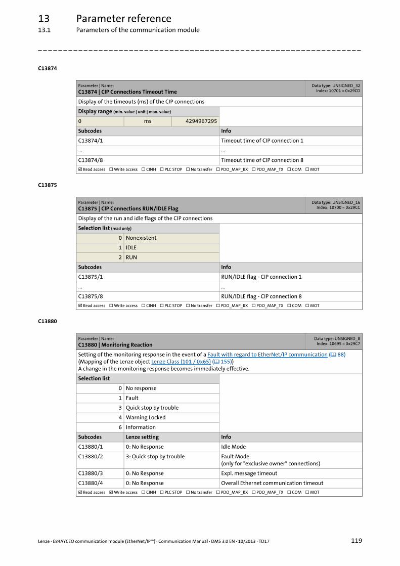
Lenze · E84AYCEO communication module (EtherNet/IP™) · Communication Manual · DMS 3.0 EN · 10/2013 · TD17 119
13 Parameter reference13.1 Parameters of the communication module
_ _ _ _ _ _ _ _ _ _ _ _ _ _ _ _ _ _ _ _ _ _ _ _ _ _ _ _ _ _ _ _ _ _ _ _ _ _ _ _ _ _ _ _ _ _ _ _ _ _ _ _ _ _ _ _ _ _ _ _ _ _ _ _
C13874
C13875
C13880
Parameter | Name:
C13874 | CIP Connections Timeout TimeData type: UNSIGNED_32
Index: 10701 = 0x29CD
Display of the timeouts (ms) of the CIP connections
Display range (min. value | unit | max. value)
0 ms 4294967295
Subcodes Info
C13874/1 Timeout time of CIP connection 1
... ...
C13874/8 Timeout time of CIP connection 8
Read access Write access CINH PLC STOP No transfer PDO_MAP_RX PDO_MAP_TX COM MOT
Parameter | Name:
C13875 | CIP Connections RUN/IDLE FlagData type: UNSIGNED_16
Index: 10700 = 0x29CC
Display of the run and idle flags of the CIP connections
Selection list (read only)
0 Nonexistent
1 IDLE
2 RUN
Subcodes Info
C13875/1 RUN/IDLE flag - CIP connection 1
... ...
C13875/8 RUN/IDLE flag - CIP connection 8
Read access Write access CINH PLC STOP No transfer PDO_MAP_RX PDO_MAP_TX COM MOT
Parameter | Name:
C13880 | Monitoring ReactionData type: UNSIGNED_8
Index: 10695 = 0x29C7
Setting of the monitoring response in the event of a Fault with regard to EtherNet/IP communication ( 88)(Mapping of the Lenze object Lenze Class (101 / 0x65) ( 155))A change in the monitoring response becomes immediately effective.
Selection list
0 No response
1 Fault
3 Quick stop by trouble
4 Warning Locked
6 Information
Subcodes Lenze setting Info
C13880/1 0: No Response Idle Mode
C13880/2 3: Quick stop by trouble Fault Mode(only for "exclusive owner" connections)
C13880/3 0: No Response Expl. message timeout
C13880/4 0: No Response Overall Ethernet communication timeout
Read access Write access CINH PLC STOP No transfer PDO_MAP_RX PDO_MAP_TX COM MOT

13 Parameter reference13.1 Parameters of the communication module
120 Lenze · E84AYCEO communication module (EtherNet/IP™) · Communication Manual · DMS 3.0 EN · 10/2013 · TD17
_ _ _ _ _ _ _ _ _ _ _ _ _ _ _ _ _ _ _ _ _ _ _ _ _ _ _ _ _ _ _ _ _ _ _ _ _ _ _ _ _ _ _ _ _ _ _ _ _ _ _ _ _ _ _ _ _ _ _ _ _ _ _ _
C13881
C13885
C13899
C13900
C13901
Parameter | Name:
C13881 | Overall Ethernet Timeout TimeData type: UNSIGNED_16
Index: 10694 = 0x29C6
Setting of the overall monitoring time (see Fault with regard to EtherNet/IP communication ( 88))A change in the monitoring response becomes immediately effective.
Setting range (min. value | unit | max. value) Lenze setting
500 ms 65535 10000 ms
Read access Write access CINH PLC STOP No transfer PDO_MAP_RX PDO_MAP_TX COM MOT
Parameter | Name:
C13885 | Clear I/O DataData type: UNSIGNED_8
Index: 10690 = 0x29C2
Setting which I/O data are to be processed by the adapter to maintain internal communication if ...• the network status of the controlling I/O connection is "Not connected" (see C13862) or• an idle event has occurred.
Changes in the setting becomes effective immediately.(See Fault with regard to EtherNet/IP communication ( 88).)
Selection list (Lenze setting printed in bold)
0 Use of last Scanner Output Data
1 Clear Scanner Output Data
Read access Write access CINH PLC STOP No transfer PDO_MAP_RX PDO_MAP_TX COM MOT
Parameter | Name:
C13899 | HostnameData type: VISIBLE_STRING
Index: 10676 = 0x29B4
Each subcode contains a string with a length of 32 bytes indicating the designation of the EtherNet/IP node.(Instance attribute 6 (Host Name) in the TCP/IP Interface Object (245 / 0xF5) ( 141))
Subcodes Lenze setting Info
C13899/1 Host name
C13899/2 Host name
Read access Write access CINH PLC STOP No transfer PDO_MAP_RX PDO_MAP_TX COM MOT
Parameter | Name:
C13900 | Firmware Product TypeData type: VISIBLE_STRING
Index: 10675 = 0x29B3
The code contains a string with a length of 8 bytes. The identification code "E84AYCEO" is output.
Read access Write access CINH PLC STOP No transfer PDO_MAP_RX PDO_MAP_TX COM MOT
Parameter | Name:
C13901 | Firmware Compilation DateData type: VISIBLE_STRING
Index: 10674 = 0x29B2
The code contains a string with a length of 20 bytes. The software creation date ("MMM DD YYYY") and time ("hh:mm:ss") are displayed (e.g. "Mar 21 2005 12:31:21").
Read access Write access CINH PLC STOP No transfer PDO_MAP_RX PDO_MAP_TX COM MOT

Lenze · E84AYCEO communication module (EtherNet/IP™) · Communication Manual · DMS 3.0 EN · 10/2013 · TD17 121
13 Parameter reference13.1 Parameters of the communication module
_ _ _ _ _ _ _ _ _ _ _ _ _ _ _ _ _ _ _ _ _ _ _ _ _ _ _ _ _ _ _ _ _ _ _ _ _ _ _ _ _ _ _ _ _ _ _ _ _ _ _ _ _ _ _ _ _ _ _ _ _ _ _ _
C13902
C13920
Parameter | Name:
C13902 | Firmware VersionData type: VISIBLE_STRING
Index: 10673 = 0x29B1
The code contains a string with a length of 11 bytes. The firmware version is displayed (e.g. "01.00.01.00").
Read access Write access CINH PLC STOP No transfer PDO_MAP_RX PDO_MAP_TX COM MOT
Parameter | Name:
C13920 | Rotary coding switches: xxx.yyy.zzz.DDDData type: UNSIGNED_8
Index: 10655 = 0x299F
Indication of the current value set by means of the rotary coding switches.Setting node addresses by means of rotary coding switches ( 40)
Display range (min. value | unit | max. value)
0 255
Read access Write access CINH PLC STOP No transfer PDO_MAP_RX PDO_MAP_TX COM MOT
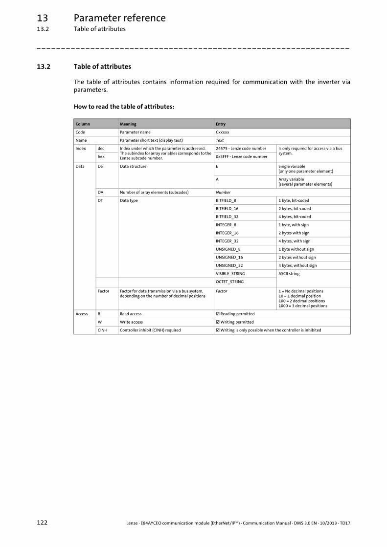
13 Parameter reference13.2 Table of attributes
122 Lenze · E84AYCEO communication module (EtherNet/IP™) · Communication Manual · DMS 3.0 EN · 10/2013 · TD17
_ _ _ _ _ _ _ _ _ _ _ _ _ _ _ _ _ _ _ _ _ _ _ _ _ _ _ _ _ _ _ _ _ _ _ _ _ _ _ _ _ _ _ _ _ _ _ _ _ _ _ _ _ _ _ _ _ _ _ _ _ _ _ _
13.2 Table of attributes
The table of attributes contains information required for communication with the inverter viaparameters.
How to read the table of attributes:
Column Meaning Entry
Code Parameter name Cxxxxx
Name Parameter short text (display text) Text
Index dec Index under which the parameter is addressed.The subindex for array variables corresponds to the Lenze subcode number.
24575 - Lenze code number Is only required for access via a bus system.
hex 0x5FFF - Lenze code number
Data DS Data structure E Single variable(only one parameter element)
A Array variable(several parameter elements)
DA Number of array elements (subcodes) Number
DT Data type BITFIELD_8 1 byte, bit-coded
BITFIELD_16 2 bytes, bit-coded
BITFIELD_32 4 bytes, bit-coded
INTEGER_8 1 byte, with sign
INTEGER_16 2 bytes with sign
INTEGER_32 4 bytes, with sign
UNSIGNED_8 1 byte without sign
UNSIGNED_16 2 bytes without sign
UNSIGNED_32 4 bytes, without sign
VISIBLE_STRING ASCII string
OCTET_STRING
Factor Factor for data transmission via a bus system, depending on the number of decimal positions
Factor 1 No decimal positions10 1 decimal position100 2 decimal positions1000 3 decimal positions
Access R Read access Reading permitted
W Write access Writing permitted
CINH Controller inhibit (CINH) required Writing is only possible when the controller is inhibited

Lenze · E84AYCEO communication module (EtherNet/IP™) · Communication Manual · DMS 3.0 EN · 10/2013 · TD17 123
13 Parameter reference13.2 Table of attributes
_ _ _ _ _ _ _ _ _ _ _ _ _ _ _ _ _ _ _ _ _ _ _ _ _ _ _ _ _ _ _ _ _ _ _ _ _ _ _ _ _ _ _ _ _ _ _ _ _ _ _ _ _ _ _ _ _ _ _ _ _ _ _ _
Table of attributes
Code Name Index Data Access
dec hex DS DA DT Factor R W CINH
C13000 IP address 11575 0x2D37 A 4 UNSIGNED_8
C13001 Subnet mask 11574 0x2D36 A 4 UNSIGNED_8
C13002 Gateway address 11573 0x2D35 A 4 UNSIGNED_8
C13003 MAC-ID 11572 0x2D34 E 1 OCTET_STRING
C13005 IP Config Control 11570 0x2D32 E 1 UNSIGNED_8 1
C13006 Multicast IP Start Address 11569 0x2D31 A 4 UNSIGNED_8
C13010 Active IP Address 11565 0x2D2D A 4 UNSIGNED_8 1
C13011 Active Subnetwork Mask 11564 0x2D2C A 4 UNSIGNED_8 1
C13012 Active gateway address 11563 0x2D2B A 4 UNSIGNED_8 1
C13016 Active Multicast IP Address 11559 0x2D27 A 4 UNSIGNED_8 1
C13017 Ethernet Config Control 11558 0x2D26 A 2 UNSIGNED_16 1
C13018 Multicast Config Alloc Control 11557 0x2D25 E 1 UNSIGNED_8 1
C13019 Multicast Config TTL Value 11556 0x2D24 E 1 UNSIGNED_8 1
C13020 Multicast Config Num Mcast 11555 0x2D23 E 1 UNSIGNED_8 1
C13021 Quality of Service (VLAN-Tagging) 11554 0x2D22 E 1 UNSIGNED_8 1
C13022 Quality of Service (DSCP) 11553 0x2D21 A 7 UNSIGNED_8
C13840 DLR Network Topology 10735 0x29EF E 1 UNSIGNED_8 1
C13841 DLR Network Status 10734 0x29EE E 1 UNSIGNED_8 1
C13842 Supervisor IP Address 10733 0x29ED A 4 UNSIGNED_8 1
C13843 Supervisor MAC ID 10732 0x29EC E 1 OCTET_STRING
C13844 Beacon Times 10731 0x29EB A 2 UNSIGNED_32 1
C13845 Beacon Frames 10730 0x29EA A 4 UNSIGNED_32 1
C13846 Address Conflict Detection 10729 0x29E9 E 1 UNSIGNED_8 1
C13847 Active Conflict Detection State 10728 0x29E8 E 1 UNSIGNED_8 1
C13848 Last Conflicted MAC ID 10727 0x29E7 E 1 OCTET_STRING
C13849 Last Conflicted IP Address 10726 0x29E6 A 4 UNSIGNED_8 1
C13850 All words to scanner 10725 0x29E5 A 16 INTEGER_16 1
C13851 All words from scanner 10724 0x29E4 A 16 INTEGER_16 1
C13852 All words to the basic device 10723 0x29E3 A 16 INTEGER_16 1
C13853 All words to the basic device 10722 0x29E2 A 16 INTEGER_16 1
C13858 Ethernet Port Statistics 10717 0x29DD A 10 UNSIGNED_32 1
C13861 CIP Module Status 10714 0x29DA E 1 UNSIGNED_16 1
C13862 CIP Network Status 10713 0x29D9 E 1 UNSIGNED_16 1
C13863 Ethernet Port 10712 0x29D8 A 2 UNSIGNED_16 1
C13870 CIP Connections State 10705 0x29D1 A 8 UNSIGNED_16 1
C13871 CIP Connections Type 10704 0x29D0 A 8 UNSIGNED_16 1
C13872 CIP Connection Triggers 10703 0x29CF A 8 UNSIGNED_16 1
C13873 CIP Connections RPI 10702 0x29CE A 8 UNSIGNED_32 1
C13874 CIP Connections Timeout Time 10701 0x29CD A 8 UNSIGNED_32 1
C13875 CIP Connections RUN/IDLE Flag 10700 0x29CC A 8 UNSIGNED_16 1
C13880 Monitoring Reaction 10695 0x29C7 A 4 UNSIGNED_8 1
C13881 Overall Ethernet Timeout Time 10694 0x29C6 E 1 UNSIGNED_16 1
C13885 Clear I/O Data 10690 0x29C2 E 1 UNSIGNED_8 1
C13899 Hostname 10676 0x29B4 A 2 VISIBLE_STRING
C13900 Firmware Product Type 10675 0x29B3 E 1 VISIBLE_STRING
C13901 Firmware Compilation Date 10674 0x29B2 E 1 VISIBLE_STRING
C13902 Firmware Version 10673 0x29B1 E 1 VISIBLE_STRING
C13920 Rotary coding switch: xxx.yyy.zzz.DDD 10655 0x299F E 1 UNSIGNED_8 1

14 Implemented CIP™ objects
124 Lenze · E84AYCEO communication module (EtherNet/IP™) · Communication Manual · DMS 3.0 EN · 10/2013 · TD17
_ _ _ _ _ _ _ _ _ _ _ _ _ _ _ _ _ _ _ _ _ _ _ _ _ _ _ _ _ _ _ _ _ _ _ _ _ _ _ _ _ _ _ _ _ _ _ _ _ _ _ _ _ _ _ _ _ _ _ _ _ _ _ _
14 Implemented CIP™ objects
An EtherNet/IP node can be seen as an accumulation of objects. An individual object is characterisedby its class, its instances and attributes. Several services such as read and write services can beapplied to these objects.
Overview of the implemented CIP objects
Note!
This chapter only describes the CIP objects implemented by Lenze and the properties supported by them (attributes, service codes etc.).
Not all object properties described in the "Common Industrial Protocol Specification" of the ODVA are supported.
"Common Industrial Protocol Specification" of the ODVA
Here you will find detailed information about the CIP objects.
CIP objects Description
General objects
Identity Object (1 / 0x01) ( 126) Identification and general information about the device
Message Router Object (2 / 0x02) ( 128) Addressing of a service for the transfer of data to any object class or instance
Assembly Object (4 / 0x04) ( 129) Input/output data of the scanner
Connection Manager Object (6 / 0x06) ( 135) Management of the internal resources for the transfer of data (implicit/explicit messaging)
EtherNet/IP objects
Device Level Ring (DLR) Object (71 / 0x47) ( 137) Status information for the DLR protocol
Quality of Service (QoS) Object (72 / 0x48) ( 139) Classification and prioritisation of the data packets for EtherNet/IP communication
TCP/IP Interface Object (245 / 0xF5) ( 141) Configuration of the TCP/IP network interface of the device
Ethernet Link Object (246 / 0xF6) ( 145) General information and status information about the Ethernet interfaces of the device
AC drive profile objects
Motor Data Object (40 / 0x28) ( 149) Data basis for motor parameters
Control Supervisor Object (41 / 0x29) ( 150) Management functions of the motor control devices.
AC Drive Object (42 / 0x2A) ( 152) Device-specific functions of the drive, e.g. speed ramps, torque control etc.
Lenze objects
Lenze Class (101 / 0x65) ( 155) Lenze error responses to EtherNet/IP errors
Lenze Class (103 / 0x67) ( 157) Image of the scanner input data
Lenze Class (104 / 0x68) ( 158) Image of the scanner output data
Lenze Class (110 / 0x6E) ( 159) Access to Lenze codes
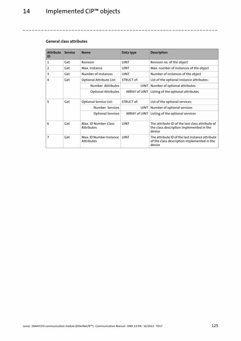
Lenze · E84AYCEO communication module (EtherNet/IP™) · Communication Manual · DMS 3.0 EN · 10/2013 · TD17 125
14 Implemented CIP™ objects
_ _ _ _ _ _ _ _ _ _ _ _ _ _ _ _ _ _ _ _ _ _ _ _ _ _ _ _ _ _ _ _ _ _ _ _ _ _ _ _ _ _ _ _ _ _ _ _ _ _ _ _ _ _ _ _ _ _ _ _ _ _ _ _
General class attributes
Attribute ID
Service Name Data type Description
1 Get Revision UINT Revision no. of the object
2 Get Max. Instance UINT Max. number of instances of the object
3 Get Number of Instances UINT Number of instances of the object
4 Get Optional Attribute List: STRUCT of: List of the optional instance attributes:
Number Attributes UINT Number of optional attributes
Optional Attributes ARRAY of UINT Listing of the optional attributes
5 Get Optional Service List: STRUCT of: List of the optional services:
Number Services UINT Number of optional services
Optional Services ARRAY of UINT Listing of the optional services
6 Get Max. ID Number Class Attributes
UINT The attribute ID of the last class attribute of the class description implemented in the device
7 Get Max. ID Number Instance Attributes
UINT The attribute ID of the last instance attribute of the class description implemented in the device

14 Implemented CIP™ objects14.1 General CIP objects
126 Lenze · E84AYCEO communication module (EtherNet/IP™) · Communication Manual · DMS 3.0 EN · 10/2013 · TD17
_ _ _ _ _ _ _ _ _ _ _ _ _ _ _ _ _ _ _ _ _ _ _ _ _ _ _ _ _ _ _ _ _ _ _ _ _ _ _ _ _ _ _ _ _ _ _ _ _ _ _ _ _ _ _ _ _ _ _ _ _ _ _ _
14.1 General CIP objects
14.1.1 Identity Object (1 / 0x01)
The "Identity Object" provides the identification and general information about the device.
Class attributes
Instance attributes
Attribute ID
Service Name Data type Value
1 Get Revision UINT 1 (0x0001)
2 Get Max. Instance UINT 1 (0x0001)
3 Get Number of Instances UINT 1 (0x0001)
6 Get Max. ID Number Class Attributes
UINT 7 (0x0007)
7 Get Max. ID Number Instance Attributes
UINT 8 (0x0008)
Attribute ID
Service Name Data type Value
1 Get Vendor ID UINT 587 (0x024B)
2 Get Device Type UINT 2 (0x0002): AC Drive
3 Get Product Code UINT 8400 (0x20D0)
4 Get Revision: STRUCT of: Firmware revision of the device
Major Revision USINT
Minor Revision USINT
5 Get Status WORD Current device status (status bits)• Instance attribute "Status" (attribute 5)
( 127)• EtherNet/IP state diagram ( 55)
6 Get Serial Number UDINT Serial number of the device
7 Get Product Name SHORT_STRING E84AYCEO
8 Get State USINT Current device state:• 0: Nonexistent• 1: Device self-testing• 2: Standby• 3: Operational• 4: Major recoverable fault• 5: Major unrecoverable fault• 6 ... 254: Reserved• 255: Standard for "Get_Attributes_All"
service(See also C13861, LED status displays ( 89))
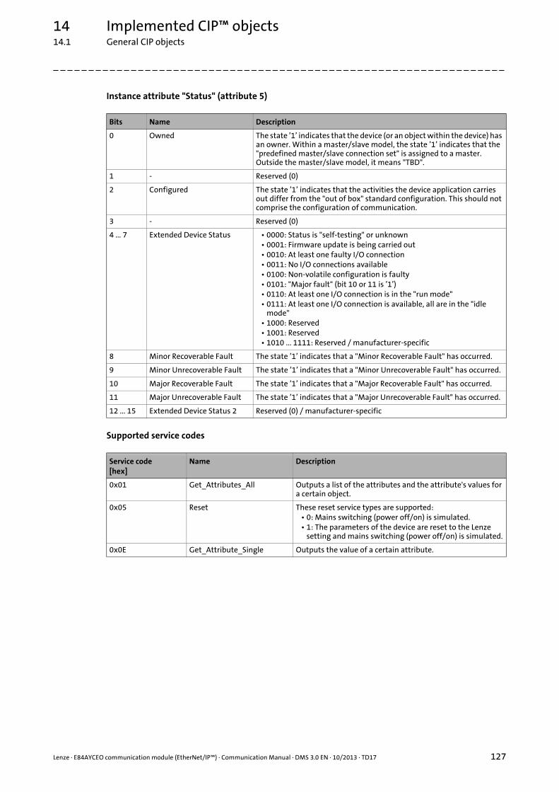
Lenze · E84AYCEO communication module (EtherNet/IP™) · Communication Manual · DMS 3.0 EN · 10/2013 · TD17 127
14 Implemented CIP™ objects14.1 General CIP objects
_ _ _ _ _ _ _ _ _ _ _ _ _ _ _ _ _ _ _ _ _ _ _ _ _ _ _ _ _ _ _ _ _ _ _ _ _ _ _ _ _ _ _ _ _ _ _ _ _ _ _ _ _ _ _ _ _ _ _ _ _ _ _ _
Instance attribute "Status" (attribute 5)
Supported service codes
Bits Name Description
0 Owned The state ’1’ indicates that the device (or an object within the device) has an owner. Within a master/slave model, the state ’1’ indicates that the "predefined master/slave connection set" is assigned to a master. Outside the master/slave model, it means "TBD".
1 - Reserved (0)
2 Configured The state ’1’ indicates that the activities the device application carries out differ from the "out of box" standard configuration. This should not comprise the configuration of communication.
3 - Reserved (0)
4 ... 7 Extended Device Status • 0000: Status is "self-testing" or unknown• 0001: Firmware update is being carried out• 0010: At least one faulty I/O connection• 0011: No I/O connections available• 0100: Non-volatile configuration is faulty• 0101: "Major fault" (bit 10 or 11 is ’1’)• 0110: At least one I/O connection is in the "run mode"• 0111: At least one I/O connection is available, all are in the "idle
mode"• 1000: Reserved• 1001: Reserved• 1010 ... 1111: Reserved / manufacturer-specific
8 Minor Recoverable Fault The state ’1’ indicates that a "Minor Recoverable Fault" has occurred.
9 Minor Unrecoverable Fault The state ’1’ indicates that a "Minor Unrecoverable Fault" has occurred.
10 Major Recoverable Fault The state ’1’ indicates that a "Major Recoverable Fault" has occurred.
11 Major Unrecoverable Fault The state ’1’ indicates that a "Major Unrecoverable Fault" has occurred.
12 ... 15 Extended Device Status 2 Reserved (0) / manufacturer-specific
Service code[hex]
Name Description
0x01 Get_Attributes_All Outputs a list of the attributes and the attribute's values for a certain object.
0x05 Reset These reset service types are supported:• 0: Mains switching (power off/on) is simulated.• 1: The parameters of the device are reset to the Lenze
setting and mains switching (power off/on) is simulated.
0x0E Get_Attribute_Single Outputs the value of a certain attribute.
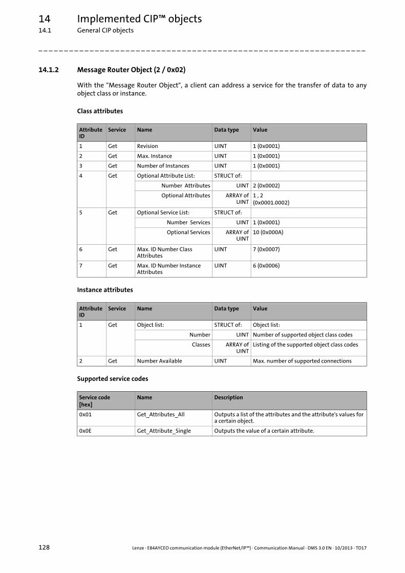
14 Implemented CIP™ objects14.1 General CIP objects
128 Lenze · E84AYCEO communication module (EtherNet/IP™) · Communication Manual · DMS 3.0 EN · 10/2013 · TD17
_ _ _ _ _ _ _ _ _ _ _ _ _ _ _ _ _ _ _ _ _ _ _ _ _ _ _ _ _ _ _ _ _ _ _ _ _ _ _ _ _ _ _ _ _ _ _ _ _ _ _ _ _ _ _ _ _ _ _ _ _ _ _ _
14.1.2 Message Router Object (2 / 0x02)
With the "Message Router Object", a client can address a service for the transfer of data to anyobject class or instance.
Class attributes
Instance attributes
Supported service codes
Attribute ID
Service Name Data type Value
1 Get Revision UINT 1 (0x0001)
2 Get Max. Instance UINT 1 (0x0001)
3 Get Number of Instances UINT 1 (0x0001)
4 Get Optional Attribute List: STRUCT of:
Number Attributes UINT 2 (0x0002)
Optional Attributes ARRAY ofUINT
1 , 2(0x0001.0002)
5 Get Optional Service List: STRUCT of:
Number Services UINT 1 (0x0001)
Optional Services ARRAY ofUINT
10 (0x000A)
6 Get Max. ID Number Class Attributes
UINT 7 (0x0007)
7 Get Max. ID Number Instance Attributes
UINT 6 (0x0006)
Attribute ID
Service Name Data type Value
1 Get Object list: STRUCT of: Object list:
Number UINT Number of supported object class codes
Classes ARRAY ofUINT
Listing of the supported object class codes
2 Get Number Available UINT Max. number of supported connections
Service code[hex]
Name Description
0x01 Get_Attributes_All Outputs a list of the attributes and the attribute's values for a certain object.
0x0E Get_Attribute_Single Outputs the value of a certain attribute.

Lenze · E84AYCEO communication module (EtherNet/IP™) · Communication Manual · DMS 3.0 EN · 10/2013 · TD17 129
14 Implemented CIP™ objects14.1 General CIP objects
_ _ _ _ _ _ _ _ _ _ _ _ _ _ _ _ _ _ _ _ _ _ _ _ _ _ _ _ _ _ _ _ _ _ _ _ _ _ _ _ _ _ _ _ _ _ _ _ _ _ _ _ _ _ _ _ _ _ _ _ _ _ _ _
14.1.3 Assembly Object (4 / 0x04)
For data exchange, the communication module supports the following assembly object instances:
The contents of the input and output data depends on the I/O data arrangement in the drive (I/Odata mapping ( 57)).
Class attributes
Application Instance ID Assembly object instance
[dec] [hex]
Lenze technology applications / user-definable parameter sets
110 0x6E Custom Output
111 0x6F Custom Input
"AC Drive Profile" application 20 0x14 Basic Speed Control Output
21 0x15 Extended Speed Control Output
22 0x16 Speed and Torque Control Output
23 0x17 Extended Speed and Torque Control Output
70 0x46 Basic Speed Control Input
71 0x47 Extended Speed Control Input
72 0x48 Speed and Torque Control Input
73 0x49 Extended Speed and Torque Control Input
Application note
An example of parameter data transfer (read/write parameters) in a "AC Drive Profile" application can be found in the download area (Application Knowledge Base) at www.Lenze.com.
Attribute ID
Service Name Data type Value
1 Get Revision UINT 2 (0x0002)
2 Get Max. Instance UINT 130 (0x0082)
3 Get Number of Instances UINT 11 (0x000B)
4 Get Optional Attribute List: STRUCT of:
Number Attributes UINT 1 (0x0001)
Optional Attributes ARRAY ofUINT
4 (0x0004)
6 Get Max. ID Number Class Attributes
UINT 7 (0x0007)
7 Get Max. ID Number Instance Attributes
UINT 4 (0x0004)

14 Implemented CIP™ objects14.1 General CIP objects
130 Lenze · E84AYCEO communication module (EtherNet/IP™) · Communication Manual · DMS 3.0 EN · 10/2013 · TD17
_ _ _ _ _ _ _ _ _ _ _ _ _ _ _ _ _ _ _ _ _ _ _ _ _ _ _ _ _ _ _ _ _ _ _ _ _ _ _ _ _ _ _ _ _ _ _ _ _ _ _ _ _ _ _ _ _ _ _ _ _ _ _ _
Instance attributes for output data of the scanner
Assembly output objects (scanner to adapter) are assumed to have a 4-byte header (32-bit "run/idleheader"). When mapping the assemblies, this header will automatically be added to the datastream by most Allen-Bradley PLC/SLC equipment.
If your PLC does not support this header (like the Rockwell PLCs do), add a preceding 32-bit headerto the output image.
You can then define the bit 0 of this header in the process image of your PLC:
• State ’0’: idle mode
• State ’1’: run mode
For the operation with Rockwell PLCs, adaptations are not required.
The Lenze Class (104 / 0x68) ( 158) provides the image of the output data of the scanner.
Attribute ID
Service Name Data type Value
3 Get / Set Data ARRAY of SINT / INT /DINT
Max. 16 bytes from the scanner to the adapter:
• 20 (0x14): Basic Speed Control Output• 21 (0x15): Extended Speed Control
Output• 22 (0x16): Speed and Torque Control
Output• 23 (0x17): Extended Speed and Torque
Control Output• 110 (0x6E): Custom OutputInstance attribute "Data" (attribute 3) ( 131)
4 Get Size UINT Number of bytes in attribute 3 (Data)

Lenze · E84AYCEO communication module (EtherNet/IP™) · Communication Manual · DMS 3.0 EN · 10/2013 · TD17 131
14 Implemented CIP™ objects14.1 General CIP objects
_ _ _ _ _ _ _ _ _ _ _ _ _ _ _ _ _ _ _ _ _ _ _ _ _ _ _ _ _ _ _ _ _ _ _ _ _ _ _ _ _ _ _ _ _ _ _ _ _ _ _ _ _ _ _ _ _ _ _ _ _ _ _ _
Instance attributes for input data of the scanner
The assembly input objects (adapter to scanner) are mapped in the adapter memory starting withbyte 0.
The input objects are transmitted in a "modeless" manner, i.e. a 4-byte header is not included in thetransfer.
So the start address in the assembly memory map is the actual start of the first assembly dataelement.
Please observe the actual assembly lengths when mapping the input objects to the controllermemory.
The Lenze Class (103 / 0x67) ( 157) provides the image of the input data of the scanner.
Instance attribute "Data" (attribute 3)
Attribute ID
Service Name Data type Value
3 Get / Set Data ARRAY of SINT / INT /DINT
Max. 16 bytes from the adapter to the scanner:
• 70 (0x46): Basic Speed Control Input• 71 (0x47): Extended Speed Control Input• 72 (0x48): Speed and Torque Control
Input• 73 (0x49): Extended Speed and Torque
Control Input• 111 (0x6F): Custom InputInstance attribute "Data" (attribute 3) ( 131)
4 Get Size UINT Number of bytes in attribute 3 (Data)
Instance Byte Bit 7 Bit 6 Bit 5 Bit 4 Bit 3 Bit 2 Bit 1 Bit 0
20(0x14)
0 FaultReset
RunFwd
1
2 Speed Reference (Low Byte)
3 Speed Reference (High Byte)
21(0x15)
0 NetRef
NetCtrl FaultReset
RunRev
RunFwd
1
2 Speed Reference (Low Byte)
3 Speed Reference (High Byte)
22(0x16)
0 FaultReset
RunFwd
1
2 Speed Reference (Low Byte)
3 Speed Reference (High Byte)
4 Torque Reference (Low Byte)
5 Torque Reference (High Byte)

14 Implemented CIP™ objects14.1 General CIP objects
132 Lenze · E84AYCEO communication module (EtherNet/IP™) · Communication Manual · DMS 3.0 EN · 10/2013 · TD17
_ _ _ _ _ _ _ _ _ _ _ _ _ _ _ _ _ _ _ _ _ _ _ _ _ _ _ _ _ _ _ _ _ _ _ _ _ _ _ _ _ _ _ _ _ _ _ _ _ _ _ _ _ _ _ _ _ _ _ _ _ _ _ _
23(0x17)
0 NetRef
NetCtrl FaultReset
RunRev
RunFwd
1
2 Speed Reference (Low Byte)
3 Speed Reference (High Byte)
4 Torque Reference (Low Byte)
5 Torque Reference (High Byte)
110 (0x6E)
0 Custom Output
... ...
31 Custom Output
70(0x46)
0 Running1(Fwd)
Faulted
1
2 Speed Actual (Low Byte)
3 Speed Actual (High Byte)
71(0x47)
0 AtReferenc
e
RefFromNet
CtrlFromNet
Ready Running2 (Rev)
Running1(Fwd)
Warning Faulted
1 Drive State
2 Speed Actual (Low Byte)
3 Speed Actual (High Byte)
72(0x48)
0 Running1(Fwd)
Faulted
1
2 Speed Actual (Low Byte)
3 Speed Actual (High Byte)
4 Torque Actual (Low Byte)
5 Torque Actual (High Byte)
73(0x49)
0 AtReferenc
e
RefFromNet
CtrlFromNet
Ready Running2 (Rev)
Running1(Fwd)
Warning Faulted
1 Drive State
2 Speed Actual (Low Byte)
3 Speed Actual (High Byte)
4 Torque Actual (Low Byte)
5 Torque Actual (High Byte)
111 (0x6F)
0 Custom Input
... ...
31 Custom Input
Note!
In order to be able to use the torque control for the assembly object instances 22 (0x16), 23 (0x17), 72 (0x48), 73 (0x49), the "DriveMode" attribute has to be written by means of explicit message transfer.
Write "DriveMode" attribute ( 154)
Instance Byte Bit 7 Bit 6 Bit 5 Bit 4 Bit 3 Bit 2 Bit 1 Bit 0

Lenze · E84AYCEO communication module (EtherNet/IP™) · Communication Manual · DMS 3.0 EN · 10/2013 · TD17 133
14 Implemented CIP™ objects14.1 General CIP objects
_ _ _ _ _ _ _ _ _ _ _ _ _ _ _ _ _ _ _ _ _ _ _ _ _ _ _ _ _ _ _ _ _ _ _ _ _ _ _ _ _ _ _ _ _ _ _ _ _ _ _ _ _ _ _ _ _ _ _ _ _ _ _ _
Data mapping of the output assemblies
Data mapping of the input assemblies
Data component[Bits 0 ... 7]
Class InstanceNumber
Attribute
Name Number Name Number
RunFwd [Bit 0] ControlSupervisor
0x29 1 Run1 3
RunRev [Bit 1] ControlSupervisor
0x29 1 Run2 4
FaultReset [Bit 2] ControlSupervisor
0x29 1 FaultRst 12
NetCtrl [Bit 5] ControlSupervisor
0x29 1 NetCtrl 5
NetRef [Bit 6] AC Drive 0x2A 1 NetRef 4
Drive Mode [Bits 0 ... 7] AC Drive 0x2A 1 DriveMode 6
Speed Reference [Bits 0 ... 7] AC Drive 0x2A 1 SpeedRef 8
Torque Reference [Bits 0 ... 7] AC Drive 0x2A 1 TorqueRef 12
Custom Output [Bits 0 ... 7]
Note!
In case of the assembly object instances 21 (0x15) and 23 (0x17), NetCtrl (Bit 5) and NetRef (Bit 6) have to be set in order that the drive can receive start/stop commands and speed/torque commands via the network.
Data component[Bits 0 ... 7]
Class InstanceNumber
Attribute
Name Number Name Number
Faulted [Bit 0] ControlSupervisor
0x29 1 Faulted 10
Warning [Bit 1] ControlSupervisor
0x29 1 Warning 11
Running1 (Fwd) [Bit 2] ControlSupervisor
0x29 1 Running1 7
Running2 (Rev) [Bit 3] ControlSupervisor
0x29 1 Running2 8
Ready [Bit 4] ControlSupervisor
0x29 1 Ready 9
CtrlFromNet [Bit 5] ControlSupervisor
0x29 1 CtrlFromNet 15
RefFromNet [Bit 6] AC Drive 0x2A 1 RefFromNet 29
At Reference [Bit 7] AC Drive 0x2A 1 AtReference 3
Drive State [Bits 0 ... 7] ControlSupervisor
0x29 1 State 6
Speed Actual [Bits 0 ... 7] AC Drive 0x2A 1 SpeedActual 7
Torque Actual [Bits 0 ... 7] AC Drive 0x2A 1 TorqueActual 11
Custom Input [Bits 0 ... 7]

14 Implemented CIP™ objects14.1 General CIP objects
134 Lenze · E84AYCEO communication module (EtherNet/IP™) · Communication Manual · DMS 3.0 EN · 10/2013 · TD17
_ _ _ _ _ _ _ _ _ _ _ _ _ _ _ _ _ _ _ _ _ _ _ _ _ _ _ _ _ _ _ _ _ _ _ _ _ _ _ _ _ _ _ _ _ _ _ _ _ _ _ _ _ _ _ _ _ _ _ _ _ _ _ _
Supported service codes
Service code[hex]
Name Description
0x0E Get_Attribute_Single Outputs the value of a certain attribute.
0x10 Set_Attribute_Single Changes the value of a certain attribute.

Lenze · E84AYCEO communication module (EtherNet/IP™) · Communication Manual · DMS 3.0 EN · 10/2013 · TD17 135
14 Implemented CIP™ objects14.1 General CIP objects
_ _ _ _ _ _ _ _ _ _ _ _ _ _ _ _ _ _ _ _ _ _ _ _ _ _ _ _ _ _ _ _ _ _ _ _ _ _ _ _ _ _ _ _ _ _ _ _ _ _ _ _ _ _ _ _ _ _ _ _ _ _ _ _
14.1.4 Connection Manager Object (6 / 0x06)
The "Connection Manager Object" manages the internal resources for the I/O data transfer (implicitmessaging) and the parameter data transfer (explicit messaging). The instance specified by the"connection manager" class refers to a "connection instance" or a "connection object".
Class attributes
Instance attributes
1) A device can reject a "Request" of the attribute with the general status code "0x09" (invalid attribute value) if the attribute value sent is unequal to zero.
Attribute ID
Service Name Data type Value
1 Get Revision UINT 1 (0x0001)
2 Get Max. Instance UINT 1 (0x0001)
3 Get Number of Instances UINT 1 (0x0001)
4 Get Optional Attribute List: STRUCT of:
Number Attributes UINT 8 (0x0008)
Optional Attributes ARRAY ofUINT
1 ... 80x0001.0002.0003.0004.0005.0006.0007.0008
6 Get Max. ID Number Class Attributes
UINT 7 (0x0007)
7 Get Max. ID Number Instance Attributes
UINT 8 (0x0008)
Attribute ID
Service Name Data type Value
1 Set 1) Open Requests UINT Number of "Forward Open Service Requests" received
2 Set 1) Open Format Rejects UINT Number of "Forward Open Service Requests" rejected due to faulty format.
3 Set 1) Open Resource Rejects UINT Number of "Forward Open Service Requests" rejected due to a lack of resources.
4 Set 1) Open Other Rejects UINT Number of "Forward Open Service Requests" rejected due to other reasons than faulty format or lack of resources.
5 Set 1) Close Requests UINT Number of "Forward Close Service Requests" received
6 Set 1) Close Format Requests UINT Number of "Forward Close Service Requests" rejected due to faulty format.
7 Set 1) Close Other Requests UINT Number of "Forward Close Service Requests" rejected due to other reasons than faulty format.
8 Set 1) Connection Timeouts UINT Total number of "Connection Timeouts" that have occurred within the connections monitored by this object.

14 Implemented CIP™ objects14.1 General CIP objects
136 Lenze · E84AYCEO communication module (EtherNet/IP™) · Communication Manual · DMS 3.0 EN · 10/2013 · TD17
_ _ _ _ _ _ _ _ _ _ _ _ _ _ _ _ _ _ _ _ _ _ _ _ _ _ _ _ _ _ _ _ _ _ _ _ _ _ _ _ _ _ _ _ _ _ _ _ _ _ _ _ _ _ _ _ _ _ _ _ _ _ _ _
Instance error messages
Supported service codes
Error code[hex]
Extended code[hex]
Error designation Description
0x000 - SUCCESS No error
0x001 0x106 OWNERSHIP_CONFLICT The connection could not be established because another connection has already occupied the required resources. It is only possible to establish an "exclusive owner" connection to the adapter.
0x001 0x119 NON-LISTEN ONLY CONNECTIONNOT OPENED
The connection could not be established because there is no "non-listen only" connection (input only, exclusive owner). The "non-listen only" connection must be of the "multicast" connection type.
0x001 0x127 INVALID_ORIGINATOR_TO_TARGET_SIZE
The resulting length of the ports mapped in the receive object PDO_RX0 does not correspond to the number of data bytes of the assembly object instance 110 (0x6E, Custom Output) defined in the scanner.
0x001 0x128 INVALID_TARGET_TO_ORIGINATOR_SIZE
The resulting length of the ports mapped in the transmit object PDO_TX0 does not correspond to the number of data bytes of the assembly object instance 111 (0x6F, Custom Input) defined in the scanner.
0x001 0x204 UNCONNECTED_REQUEST_TIMED_OUT
The adapter does not respond to the establishment of the connection.
• There might be no physical connection.• The adapter is switched off.• The adapter has an invalid IP configuration.
0x001 0x320 ACCESS_CONTENTION Manufacturer-specific error:• The configurations of the assembly input and output
objects are mixed up.• The connection could not be established because another
connection has already occupied the required resources. It is only possible to establish an "exclusive owner" connection to the adapter.
0x001 0x111 ROUTER_EXT_ERR_RPI_NOT_SUPPORTED
The RPI set for a connection is not supported.• Min. class 1 RPI = 4 ms• Min. class-3-RPI = 10 ms
0x001 0x112 RROUTER_EXT_ERR_RPI_VALUE_NOT_ACCEPTABLE
The RPI set for a connection is not supported.• Min. class 1 RPI = 4 ms• Min. class-3-RPI = 10 ms
0x001 0x123 ROUTER_EXT_ERR_INVALID_TO_ CONNECTION_TYPE
The output image connection type is invalid or not supported.
0x001 0x124 ROUTER_EXT_ERR_INVALID_TO_ CONNECTION_TYPE
The input image connection type is invalid or not supported.
0x001 0x12A ROUTER_EXT_ERR_INVALID_ CONSUMING_PATH
The path specification for the output data from the scanner is invalid.
0x001 0x12B ROUTER_EXT_ERR_INVALID_ PRODUCING_PATH
The path specification for the input data to the scanner is invalid.
Service code[hex]
Name Description
0x54 Forward_Open Opens a CIP connection from the PLC to the target drive.
0x4E Forward_Close Closes a CIP connection from the PLC to the target drive.
0x0E Get_Attribute_Single Outputs the value of a certain attribute.
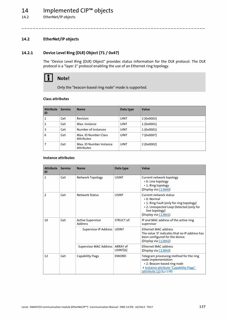
Lenze · E84AYCEO communication module (EtherNet/IP™) · Communication Manual · DMS 3.0 EN · 10/2013 · TD17 137
14 Implemented CIP™ objects14.2 EtherNet/IP objects
_ _ _ _ _ _ _ _ _ _ _ _ _ _ _ _ _ _ _ _ _ _ _ _ _ _ _ _ _ _ _ _ _ _ _ _ _ _ _ _ _ _ _ _ _ _ _ _ _ _ _ _ _ _ _ _ _ _ _ _ _ _ _ _
14.2 EtherNet/IP objects
14.2.1 Device Level Ring (DLR) Object (71 / 0x47)
The "Device Level Ring (DLR) Object" provides status information for the DLR protocol. The DLRprotocol is a "layer 2" protocol enabling the use of an Ethernet ring topology.
Class attributes
Instance attributes
Note!
Only the "beacon-based ring node" mode is supported.
Attribute ID
Service Name Data type Value
1 Get Revision UINT 2 (0x0002)
2 Get Max. Instance UINT 1 (0x0001)
3 Get Number of Instances UINT 1 (0x0001)
6 Get Max. ID Number Class Attributes
UINT 7 (0x0007)
7 Get Max. ID Number Instance Attributes
UINT 2 (0x0002)
Attribute ID
Service Name Data type Value
1 Get Network Topology USINT Current network topology• 0: Line topology• 1: Ring topology
(Display via C13840)
2 Get Network Status USINT Current network status• 0: Normal• 1: Ring Fault (only for ring topology)• 2: Unexpected Loop Detected (only for
line topology)(Display via C13841)
10 Get Active Supervisor Address
STRUCT of: IP and MAC address of the active ring supervisor
Supervisor IP Address UDINT Ethernet MAC addressThe value ’0’ indicates that no IP address has been configured for the device.(Display via C13842)
Supervisor MAC Address ARRAY of USINT[6]
Ethernet MAC address(Display via C13843)
12 Get Capability Flags DWORD Telegram processing method for the ring node implementation
• 2: Beacon-based ring nodeInstance attribute "Capability Flags" (attribute 12) ( 138)
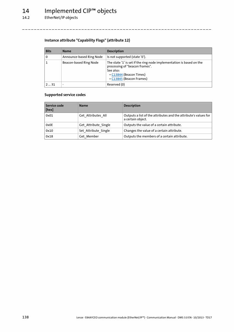
14 Implemented CIP™ objects14.2 EtherNet/IP objects
138 Lenze · E84AYCEO communication module (EtherNet/IP™) · Communication Manual · DMS 3.0 EN · 10/2013 · TD17
_ _ _ _ _ _ _ _ _ _ _ _ _ _ _ _ _ _ _ _ _ _ _ _ _ _ _ _ _ _ _ _ _ _ _ _ _ _ _ _ _ _ _ _ _ _ _ _ _ _ _ _ _ _ _ _ _ _ _ _ _ _ _ _
Instance attribute "Capability Flags" (attribute 12)
Supported service codes
Bits Name Description
0 Announce-based Ring Node Is not supported (state ’0’).
1 Beacon-based Ring Node The state ’1’ is set if the ring node implementation is based on the processing of "beacon frames".See also:
• C13844 (Beacon Times)• C13845 (Beacon Frames)
2 ... 31 - Reserved (0)
Service code[hex]
Name Description
0x01 Get_Attributes_All Outputs a list of the attributes and the attribute's values for a certain object.
0x0E Get_Attribute_Single Outputs the value of a certain attribute.
0x10 Set_Attribute_Single Changes the value of a certain attribute.
0x18 Get_Member Outputs the members of a certain attribute.

Lenze · E84AYCEO communication module (EtherNet/IP™) · Communication Manual · DMS 3.0 EN · 10/2013 · TD17 139
14 Implemented CIP™ objects14.2 EtherNet/IP objects
_ _ _ _ _ _ _ _ _ _ _ _ _ _ _ _ _ _ _ _ _ _ _ _ _ _ _ _ _ _ _ _ _ _ _ _ _ _ _ _ _ _ _ _ _ _ _ _ _ _ _ _ _ _ _ _ _ _ _ _ _ _ _ _
14.2.2 Quality of Service (QoS) Object (72 / 0x48)
The "Quality of Service (QoS) Object" enables different classifications and prioritisations of the datapackets for EtherNet/IP communication. For this purpose, the EtherNet/IP messages are markedwith "802.1Q tags" and "Differentiated Services Codepoints" (DSCP).
Class attributes
Instance attributes
The instance attributes act independently of each other.
The DSCP values are used for the IP headers.
Irrespective of this, VLAN tagging can be activated in addition (C13021 = 1).
The VLAN ID of Lenze devices is ’0’.
The VLAN priority results from the DSCP values configured.
Changes in the attribute values will only take effect after a reset of the device ("power off/on" or"type 0 reset").
Attribute ID
Service Name Data type Value
1 Get Revision UINT 1 (0x0001)
2 Get Max. Instance UINT 1 (0x0001)
3 Get Number of Instances UINT 1 (0x0001)
6 Get Max. ID Number Class Attributes
UINT 7 (0x0007)
7 Get Max. ID Number Instance Attributes
UINT 8 (0x0008)
Note!
Before activating VLAN tagging, please ensure that all involved components support VLAN tagging. It may occur that the devices not supporting VLAN tagging cannot be accessed anymore.
Attribute ID
Service Name Data type Value
1 Set 802.1Q Tag Enable USINT Enables the sending of data packets with 802.1Q tags (C13021)
• 0: No use of 802.1Q tags (Lenze setting)• 1: Use of 802.1Q tags
4 Set DSCP Urgent USINT 55: Urgent/imperative messagesIs not supported at the moment.
5 Set DSCP Scheduled USINT 47: Scheduled messages(Can only be used for "exclusive owner" connections.)(C13022/4)
6 Set DSCP High USINT 43: Messages with high priority(Can only be used for "input only" and "listen only" connections.)(C13022/5)

14 Implemented CIP™ objects14.2 EtherNet/IP objects
140 Lenze · E84AYCEO communication module (EtherNet/IP™) · Communication Manual · DMS 3.0 EN · 10/2013 · TD17
_ _ _ _ _ _ _ _ _ _ _ _ _ _ _ _ _ _ _ _ _ _ _ _ _ _ _ _ _ _ _ _ _ _ _ _ _ _ _ _ _ _ _ _ _ _ _ _ _ _ _ _ _ _ _ _ _ _ _ _ _ _ _ _
Supported service codes
7 Set DSCP Low USINT 31: Messages with low priorityIs not supported at the moment.
8 Set DSCP Explicit USINT 27: "Explicit messages" (parameter data)(C13022/7)
Service code[hex]
Name Description
0x0E Get_Attribute_Single Outputs the value of a certain attribute.
0x10 Set_Attribute_Single Changes the value of a certain attribute.
Attribute ID
Service Name Data type Value

Lenze · E84AYCEO communication module (EtherNet/IP™) · Communication Manual · DMS 3.0 EN · 10/2013 · TD17 141
14 Implemented CIP™ objects14.2 EtherNet/IP objects
_ _ _ _ _ _ _ _ _ _ _ _ _ _ _ _ _ _ _ _ _ _ _ _ _ _ _ _ _ _ _ _ _ _ _ _ _ _ _ _ _ _ _ _ _ _ _ _ _ _ _ _ _ _ _ _ _ _ _ _ _ _ _ _
14.2.3 TCP/IP Interface Object (245 / 0xF5)
The "TCP/IP Interface Object" serves to configure the TCP/IP network interface of the device.
Class attributes
Instance attributes
Attribute ID
Service Name Data type Value
1 Get Revision UINT 2 (0x0002)
2 Get Max. Instance UINT 1 (0x0001)
3 Get Number of Instances UINT 1 (0x0001)
4 Get Optional Attribute List: STRUCT of:
Number Attributes UINT 4 (0x0004)
Optional Attributes ARRAY ofUINT
8 ... 11(0x0008.0009.000A.000B)
6 Get Max. ID Number Class Attributes
UINT 0x0007
7 Get Max. ID Number Instance Attributes
UINT 0x000B
Note!
Write access to attribute 3 (Configuration Control) permanently saves the TCP/IP configuration defined in attribute 5.
If the TCP/IP configuration defined in attribute 5 is to be used as a "static IP" during the start-up, "0 = use static TCP/IP configuration" must be set in attribute 3.
Attribute ID
Service Name Data type Value
1 Get Status DWORD Current status of the TCP/IP network interfaceInstance attribute "Status" (attribute 1) ( 143)
2 Get Configuration Capability DWORD Possible options for TCP/IP configurationInstance attribute "Configuration Capability" (attribute 2) ( 143)
3 Get / Set Configuration Control DWORD Selection of how the TCP/IP configuration is to be made (C13005):Possible values for bits 0 ... 3:
• 0000: Use static TCP/IP config.• 0001: TCP/IP config. via BOOTP• 0010: TCP/IP config. via DHCP
Bits 4 ... 31 are reserved (0).
4 Get Physical Link Object: STRUCT of: Path to "Physical Link Object"
Path Size UINT 2 (0x0002)
Path paddedEPATH
• 32 (0x0020)• 246 (0x00F6)• 36 (0x0024)• 1 (0x0001)
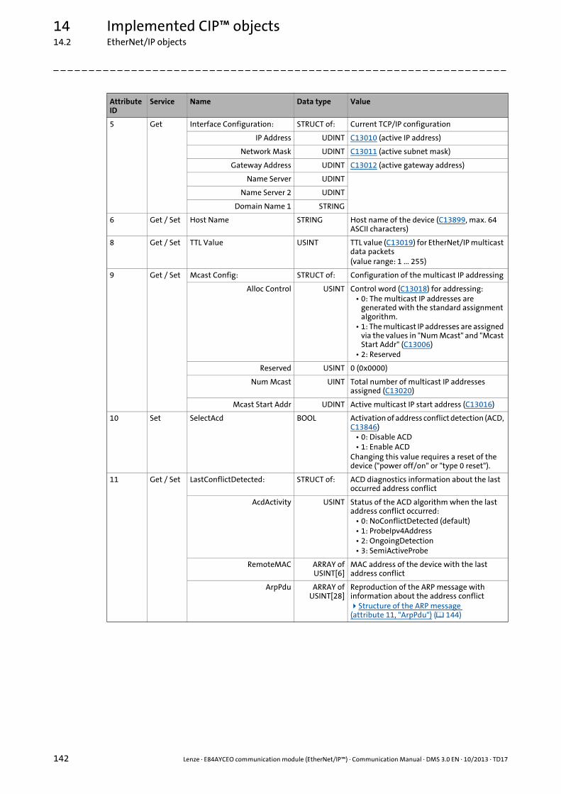
14 Implemented CIP™ objects14.2 EtherNet/IP objects
142 Lenze · E84AYCEO communication module (EtherNet/IP™) · Communication Manual · DMS 3.0 EN · 10/2013 · TD17
_ _ _ _ _ _ _ _ _ _ _ _ _ _ _ _ _ _ _ _ _ _ _ _ _ _ _ _ _ _ _ _ _ _ _ _ _ _ _ _ _ _ _ _ _ _ _ _ _ _ _ _ _ _ _ _ _ _ _ _ _ _ _ _
5 Get Interface Configuration: STRUCT of: Current TCP/IP configuration
IP Address UDINT C13010 (active IP address)
Network Mask UDINT C13011 (active subnet mask)
Gateway Address UDINT C13012 (active gateway address)
Name Server UDINT
Name Server 2 UDINT
Domain Name 1 STRING
6 Get / Set Host Name STRING Host name of the device (C13899, max. 64 ASCII characters)
8 Get / Set TTL Value USINT TTL value (C13019) for EtherNet/IP multicast data packets(value range: 1 ... 255)
9 Get / Set Mcast Config: STRUCT of: Configuration of the multicast IP addressing
Alloc Control USINT Control word (C13018) for addressing:• 0: The multicast IP addresses are
generated with the standard assignment algorithm.
• 1: The multicast IP addresses are assigned via the values in "Num Mcast" and "Mcast Start Addr" (C13006)
• 2: Reserved
Reserved USINT 0 (0x0000)
Num Mcast UINT Total number of multicast IP addresses assigned (C13020)
Mcast Start Addr UDINT Active multicast IP start address (C13016)
10 Set SelectAcd BOOL Activation of address conflict detection (ACD, C13846)
• 0: Disable ACD• 1: Enable ACD
Changing this value requires a reset of the device ("power off/on" or "type 0 reset").
11 Get / Set LastConflictDetected: STRUCT of: ACD diagnostics information about the last occurred address conflict
AcdActivity USINT Status of the ACD algorithm when the last address conflict occurred:
• 0: NoConflictDetected (default)• 1: ProbeIpv4Address• 2: OngoingDetection• 3: SemiActiveProbe
RemoteMAC ARRAY ofUSINT[6]
MAC address of the device with the last address conflict
ArpPdu ARRAY ofUSINT[28]
Reproduction of the ARP message with information about the address conflictStructure of the ARP message (attribute 11, "ArpPdu") ( 144)
Attribute ID
Service Name Data type Value

Lenze · E84AYCEO communication module (EtherNet/IP™) · Communication Manual · DMS 3.0 EN · 10/2013 · TD17 143
14 Implemented CIP™ objects14.2 EtherNet/IP objects
_ _ _ _ _ _ _ _ _ _ _ _ _ _ _ _ _ _ _ _ _ _ _ _ _ _ _ _ _ _ _ _ _ _ _ _ _ _ _ _ _ _ _ _ _ _ _ _ _ _ _ _ _ _ _ _ _ _ _ _ _ _ _ _
Instance attribute "Status" (attribute 1)
Instance attribute "Configuration Capability" (attribute 2)
Bits Name Description
0 ... 3 Interface Configuration Status
• 0000: No TCP/IP configuration available (attribute 5)• 0001: Valid TCP/IP configuration (attribute 5) via BOOTP, DHCP or
static/permanent storage• 0010 ... 1111: Reserved
4 Mcast Pending This bit indicates a pending change of the multicast configuration in attribute 9 (Mcast Config) and/or the TTL value (C13019). It is set to ’1’ if either a multicast attribute or the TTL value is set.The pending change will only take effect after a reset of the device ("power off/on" or "type 0 reset"). This bit is then reset to ’0’.
5 Interface Configuration Pending
This bit indicates a pending change of the TCP/IP configuration in attribute 5 (Interface Configuration). It is set to ’1’ if an attribute is set.The pending change will only take effect after a reset of the device ("power off/on" or "type 0 reset").
6 AcdStatus Display of the status of address conflict detection (ACD, C13847):• 0: No address conflict detected• 1: Address conflict detected
7 ... 31 - Reserved (0)
Bits Name Description
0 BOOTP Client The state ’1’ indicates that BOOTP is used for the TCP/IP configuration of the device.
1 DNS Client Is not supported (state ’0’).
2 DHCP Client The state ’1’ indicates that DHCP is used for the TCP/IP configuration of the device.
3 DHCP-DNS Update Is not supported (state ’0’).
4 Configuration Settable The state ’1’ indicates that the TCP/IP configuration can be set in attribute 5 (Interface Configuration).
5 Hardware Configurable Is not supported (state ’0’).
6 Interface Configuration Change Requires Reset
The state ’1’ indicates that changes of the TCP/IP configuration in attribute 5 (Interface Configuration) will only take effect after a reset of the device ("power off/on" or "type 0 reset").The state ’0’ is not supported (changes becoming effective immediately).
7 AcdCapable The state ’1’ indicates that the device is provided with address conflict detection (ACD).
8 ... 31 - Reserved (0)

14 Implemented CIP™ objects14.2 EtherNet/IP objects
144 Lenze · E84AYCEO communication module (EtherNet/IP™) · Communication Manual · DMS 3.0 EN · 10/2013 · TD17
_ _ _ _ _ _ _ _ _ _ _ _ _ _ _ _ _ _ _ _ _ _ _ _ _ _ _ _ _ _ _ _ _ _ _ _ _ _ _ _ _ _ _ _ _ _ _ _ _ _ _ _ _ _ _ _ _ _ _ _ _ _ _ _
Structure of the ARP message (attribute 11, "ArpPdu")
Supported service codes
Field size[Bytes]
Field name Value
2 Hardware Address Type 1: Ethernet H/W
2 Protocol Address Type 0x0800: IP
1 HADDR LEN 6: Ethernet H/W
1 PADDR LEN 4: IP
2 OPERATION 1: Request2: Response
6 SENDER HADDR H/W address of the sender
4 SENDER PADDR Protocol address of the sender
6 TARGET HADDR H/W address of the target
4 TARGET PADDR Protocol address of the target
Service code[hex]
Name Description
0x01 Get_Attributes_All Outputs a list of the attributes and the attribute's values for a certain object.
0x0E Get_Attribute_Single Outputs the value of a certain attribute.
0x10 Set_Attribute_Single Changes the value of a certain attribute.
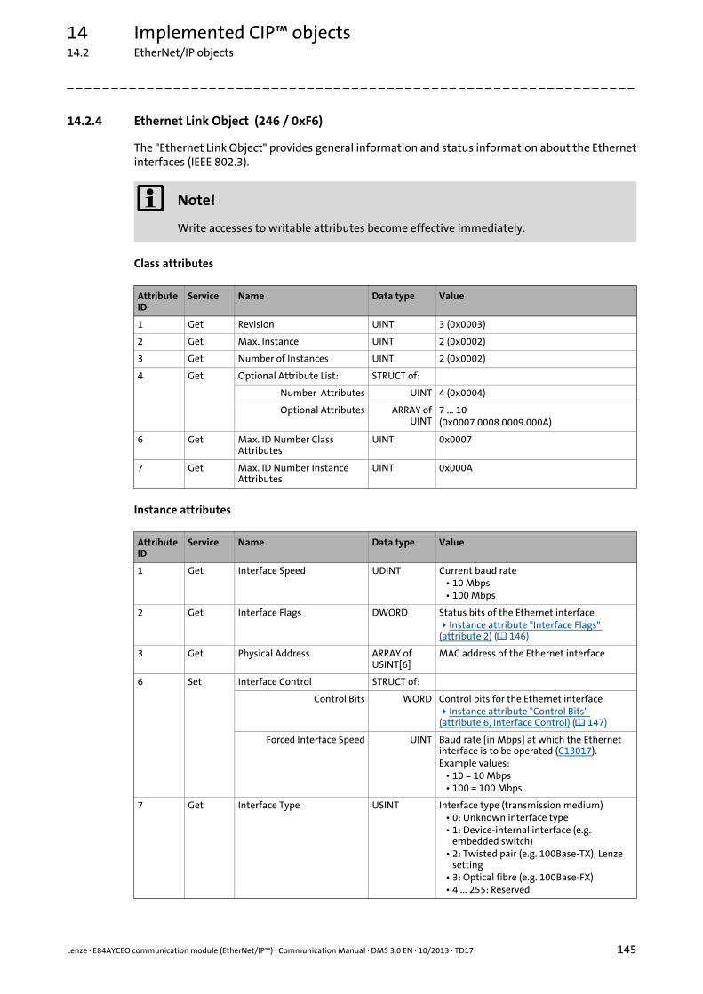
Lenze · E84AYCEO communication module (EtherNet/IP™) · Communication Manual · DMS 3.0 EN · 10/2013 · TD17 145
14 Implemented CIP™ objects14.2 EtherNet/IP objects
_ _ _ _ _ _ _ _ _ _ _ _ _ _ _ _ _ _ _ _ _ _ _ _ _ _ _ _ _ _ _ _ _ _ _ _ _ _ _ _ _ _ _ _ _ _ _ _ _ _ _ _ _ _ _ _ _ _ _ _ _ _ _ _
14.2.4 Ethernet Link Object (246 / 0xF6)
The "Ethernet Link Object" provides general information and status information about the Ethernetinterfaces (IEEE 802.3).
Class attributes
Instance attributes
Note!
Write accesses to writable attributes become effective immediately.
Attribute ID
Service Name Data type Value
1 Get Revision UINT 3 (0x0003)
2 Get Max. Instance UINT 2 (0x0002)
3 Get Number of Instances UINT 2 (0x0002)
4 Get Optional Attribute List: STRUCT of:
Number Attributes UINT 4 (0x0004)
Optional Attributes ARRAY ofUINT
7 ... 10(0x0007.0008.0009.000A)
6 Get Max. ID Number Class Attributes
UINT 0x0007
7 Get Max. ID Number Instance Attributes
UINT 0x000A
Attribute ID
Service Name Data type Value
1 Get Interface Speed UDINT Current baud rate• 10 Mbps• 100 Mbps
2 Get Interface Flags DWORD Status bits of the Ethernet interfaceInstance attribute "Interface Flags" (attribute 2) ( 146)
3 Get Physical Address ARRAY of USINT[6]
MAC address of the Ethernet interface
6 Set Interface Control STRUCT of:
Control Bits WORD Control bits for the Ethernet interfaceInstance attribute "Control Bits" (attribute 6, Interface Control) ( 147)
Forced Interface Speed UINT Baud rate [in Mbps] at which the Ethernet interface is to be operated (C13017).Example values:
• 10 = 10 Mbps• 100 = 100 Mbps
7 Get Interface Type USINT Interface type (transmission medium)• 0: Unknown interface type• 1: Device-internal interface (e.g.
embedded switch)• 2: Twisted pair (e.g. 100Base-TX), Lenze
setting• 3: Optical fibre (e.g. 100Base-FX)• 4 ... 255: Reserved

14 Implemented CIP™ objects14.2 EtherNet/IP objects
146 Lenze · E84AYCEO communication module (EtherNet/IP™) · Communication Manual · DMS 3.0 EN · 10/2013 · TD17
_ _ _ _ _ _ _ _ _ _ _ _ _ _ _ _ _ _ _ _ _ _ _ _ _ _ _ _ _ _ _ _ _ _ _ _ _ _ _ _ _ _ _ _ _ _ _ _ _ _ _ _ _ _ _ _ _ _ _ _ _ _ _ _
Instance attribute "Interface Flags" (attribute 2)
8 Get Interface State USINT Current operating status of the Ethernet interface
• 0: Unknown status• 1: Enable (The interface can send and
receive data.)• 2: Disable• 3: Testing• 4 ... 255: Reserved
9 Set Admin State USINT Administrative status• 0: Reserved• 1: Enable• 2: Disable• 3 ... 255: Reserved
10 Get Interface Label SHORT_STRING
Text for the identification/designation of the Ethernet interface
Bits Name Description
0 Link Status This bit indicates whether the Ethernet interface is connected to an active network.
• 0: No Ethernet connection available• 1: Ethernet connection available
1 Half/Full Duplex This bit indicates the current transmission mode of the Ethernet interface.
• 0: Half duplex• 1: Full duplex
Note: If "Link Status" bit = 0, it is not possible to determine the value of the "Half/Full Duplex" bit.
2 ... 4 Negotiation Status These bits indicate the status of "Link Auto-Negotiation".• 000: "Link Auto-Negotiation" is being processed.• 001: "Link Auto-Negotiation" and speed detection have failed.
• Use the standard baud rate and transmission mode values.• The standard values depend on the product; recommended values
are ’10 Mbps’ and ’Half Duplex’.• 010: "Link Auto-Negotiation" has failed, but a baud rate has been
detected.• Use the recommended value (’Half Duplex’) for the transmission
mode .• 011: "Link Auto-Negotiation" and speed detection have been
successful.• 100: No "Link Auto-Negotiation" active.
5 Manual Setting Requires Reset
Reset after changes in the link parameters• 0: The Ethernet interface can activate changes in the link parameters
(auto-negotiation, transmission mode, baud rate) automatically.• 1: If the link parameters (auto-negotiation, transmission mode, baud
rate) are changed, the device must be reset ("power off/on" or "type 0 reset").
6 Local Hardware Fault Hardware fault detection• 0: No hardware fault has been detected on the Ethernet interface.• 1: A hardware fault has been detected on the Ethernet interface.
7 ... 31 - Reserved (0)
Attribute ID
Service Name Data type Value

Lenze · E84AYCEO communication module (EtherNet/IP™) · Communication Manual · DMS 3.0 EN · 10/2013 · TD17 147
14 Implemented CIP™ objects14.2 EtherNet/IP objects
_ _ _ _ _ _ _ _ _ _ _ _ _ _ _ _ _ _ _ _ _ _ _ _ _ _ _ _ _ _ _ _ _ _ _ _ _ _ _ _ _ _ _ _ _ _ _ _ _ _ _ _ _ _ _ _ _ _ _ _ _ _ _ _
Instance attribute "Control Bits" (attribute 6, Interface Control)
Supported service codes
Bits Name Description
0 Auto-negotiate Activation of "Link Auto-Negotiation"• 0: "Link Auto-Negotiation" is not active.
The device uses the settings of the bits "Forced Duplex Mode" (bit 1) and "Forced Interface Speed" (see attribute 6, Interface Control).
• 1: "Link Auto-Negotiation" is active.
1 Forced Duplex Mode If "Auto-negotiate" bit = 0, this bit indicates the transmission mode to be used.
• 0: Half duplex• 1: Full duplex
2 ... 15 - Reserved (0)
Service code[hex]
Name Description
0x01 Get_Attributes_All Outputs a list of the attributes and the attribute's values for a certain object.
0x0E Get_Attribute_Single Outputs the value of a certain attribute.
0x10 Set_Attribute_Single Changes the value of a certain attribute.

14 Implemented CIP™ objects14.3 "AC Drive Profile" objects
148 Lenze · E84AYCEO communication module (EtherNet/IP™) · Communication Manual · DMS 3.0 EN · 10/2013 · TD17
_ _ _ _ _ _ _ _ _ _ _ _ _ _ _ _ _ _ _ _ _ _ _ _ _ _ _ _ _ _ _ _ _ _ _ _ _ _ _ _ _ _ _ _ _ _ _ _ _ _ _ _ _ _ _ _ _ _ _ _ _ _ _ _
14.3 "AC Drive Profile" objects
From inverter drive version V13.00 and communication module version V01.02, the EtherNet/IPspecified "AC Drive Profile" is supported.
The standard device code C00005 = "1100: AC Drive Profile" serves to select the "AC Drive Profile"application.
The "AC Drive Profile" contains ...
• the data basis for motor parameters,
• management functions of the motor control devices,
• Device-specific functions of the drive, e.g. speed ramps, torque control etc.
For using the "AC Drive Profile", the following assembly object instances in the host (scanner) haveto be used:
See also Assembly Object (4 / 0x04) ( 129)
Instance ID Assembly object instance
[dec] [hex]
20 0x14 Basic Speed Control Output Outputs: From the scanner to the adapter
21 0x15 Extended Speed Control Output
22 0x16 Speed and Torque Control Output
23 0x17 Extended Speed and Torque Control Output
70 0x46 Basic Speed Control Input Inputs: From the adapter to the scanner
71 0x47 Extended Speed Control Input
72 0x48 Speed and Torque Control Input
73 0x49 Extended Speed and Torque Control Input
Software manual / »Engineer« online help for the Inverter Drive 8400
Here you can find detailed information on how to use the "AC Drive Profile".

Lenze · E84AYCEO communication module (EtherNet/IP™) · Communication Manual · DMS 3.0 EN · 10/2013 · TD17 149
14 Implemented CIP™ objects14.3 "AC Drive Profile" objects
_ _ _ _ _ _ _ _ _ _ _ _ _ _ _ _ _ _ _ _ _ _ _ _ _ _ _ _ _ _ _ _ _ _ _ _ _ _ _ _ _ _ _ _ _ _ _ _ _ _ _ _ _ _ _ _ _ _ _ _ _ _ _ _
14.3.1 Motor Data Object (40 / 0x28)
The "Motor Data Object" provides a data basis for motor parameters.
Class attributes
Instance attributes
Instance attributes for AC motor types
For a write access to the attributes RatedCurrent and RatedVoltage, the controller enable (RFR = 0)has to be deactivated.
Supported service codes
Attribute ID
Service Name Data type Value
1 Get Revision UINT 1 (0x0001)
2 Get Max. Instance UINT 1 (0x0001)
3 Get Number of Instances UINT 1 (0x0001)
Attribute ID
Service Name Data type Value
1 Get NumAttr USINT Number of supported attributes
2 Get Attributes ARRAY of USINT
Listing of the supported attributes
3 Get / Set MotorType USINT AC motor type• 6: Wound-rotor induction motor• 7: Squirrel-cage induction motor
Attribute ID
Service Name Data type Value
6 Get / Set RatedCurrent UINT Rated stator current [100mA]
7 Get / Set RatedVoltage UINT Rated base voltage [V]
Service code[hex]
Name Description
0x01 Get_Attributes_All Outputs a list of the attributes and the attribute's values for a certain object.
0x0E Get_Attribute_Single Outputs the value of a certain attribute.
0x10 Set_Attribute_Single Changes the value of a certain attribute.
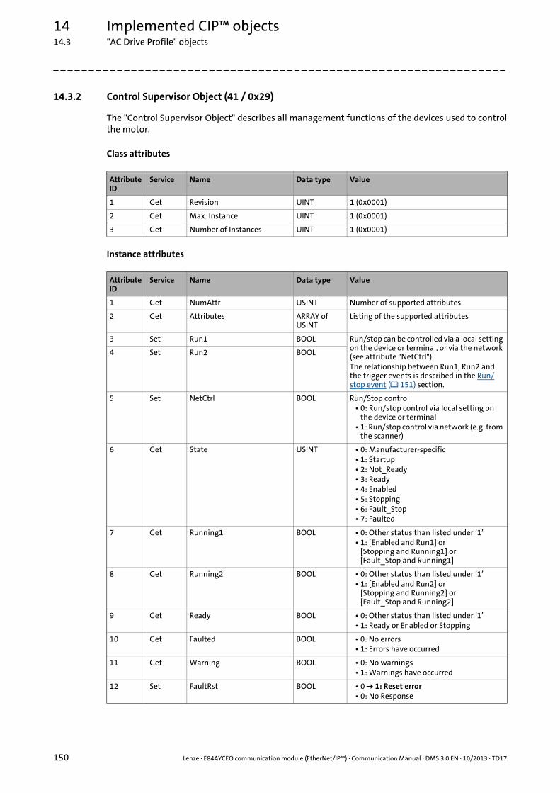
14 Implemented CIP™ objects14.3 "AC Drive Profile" objects
150 Lenze · E84AYCEO communication module (EtherNet/IP™) · Communication Manual · DMS 3.0 EN · 10/2013 · TD17
_ _ _ _ _ _ _ _ _ _ _ _ _ _ _ _ _ _ _ _ _ _ _ _ _ _ _ _ _ _ _ _ _ _ _ _ _ _ _ _ _ _ _ _ _ _ _ _ _ _ _ _ _ _ _ _ _ _ _ _ _ _ _ _
14.3.2 Control Supervisor Object (41 / 0x29)
The "Control Supervisor Object" describes all management functions of the devices used to controlthe motor.
Class attributes
Instance attributes
Attribute ID
Service Name Data type Value
1 Get Revision UINT 1 (0x0001)
2 Get Max. Instance UINT 1 (0x0001)
3 Get Number of Instances UINT 1 (0x0001)
Attribute ID
Service Name Data type Value
1 Get NumAttr USINT Number of supported attributes
2 Get Attributes ARRAY of USINT
Listing of the supported attributes
3 Set Run1 BOOL Run/stop can be controlled via a local setting on the device or terminal, or via the network (see attribute "NetCtrl").The relationship between Run1, Run2 and the trigger events is described in the Run/stop event ( 151) section.
4 Set Run2 BOOL
5 Set NetCtrl BOOL Run/Stop control• 0: Run/stop control via local setting on
the device or terminal• 1: Run/stop control via network (e.g. from
the scanner)
6 Get State USINT • 0: Manufacturer-specific• 1: Startup• 2: Not_Ready• 3: Ready• 4: Enabled• 5: Stopping• 6: Fault_Stop• 7: Faulted
7 Get Running1 BOOL • 0: Other status than listed under ’1’• 1: [Enabled and Run1] or
[Stopping and Running1] or[Fault_Stop and Running1]
8 Get Running2 BOOL • 0: Other status than listed under ’1’• 1: [Enabled and Run2] or
[Stopping and Running2] or[Fault_Stop and Running2]
9 Get Ready BOOL • 0: Other status than listed under ’1’• 1: Ready or Enabled or Stopping
10 Get Faulted BOOL • 0: No errors• 1: Errors have occurred
11 Get Warning BOOL • 0: No warnings• 1: Warnings have occurred
12 Set FaultRst BOOL • 0 1: Reset error• 0: No Response
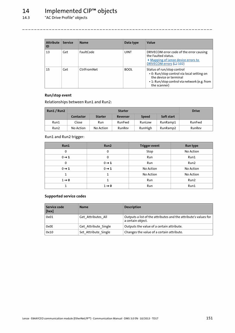
Lenze · E84AYCEO communication module (EtherNet/IP™) · Communication Manual · DMS 3.0 EN · 10/2013 · TD17 151
14 Implemented CIP™ objects14.3 "AC Drive Profile" objects
_ _ _ _ _ _ _ _ _ _ _ _ _ _ _ _ _ _ _ _ _ _ _ _ _ _ _ _ _ _ _ _ _ _ _ _ _ _ _ _ _ _ _ _ _ _ _ _ _ _ _ _ _ _ _ _ _ _ _ _ _ _ _ _
Run/stop event
Relationships between Run1 and Run2:
Run1 and Run2 trigger:
Supported service codes
13 Get FaultCode UINT DRIVECOM error code of the error causing the Faulted status.Mapping of Lenze device errors to DRIVECOM errors ( 102)
15 Get CtrlFromNet BOOL Status of run/stop control• 0: Run/stop control via local setting on
the device or terminal• 1: Run/stop control via network (e.g. from
the scanner)
Run1 / Run2 Starter Drive
Contactor Starter Reverser Speed Soft start
Run1 Close Run RunFwd RunLow RunRamp1 RunFwd
Run2 No Action No Action RunRev RunHigh RunRamp2 RunRev
Run1 Run2 Trigger event Run type
0 0 Stop No Action
0 1 0 Run Run1
0 0 1 Run Run2
0 1 0 1 No Action No Action
1 1 No Action No Action
1 0 1 Run Run2
1 1 0 Run Run1
Service code[hex]
Name Description
0x01 Get_Attributes_All Outputs a list of the attributes and the attribute's values for a certain object.
0x0E Get_Attribute_Single Outputs the value of a certain attribute.
0x10 Set_Attribute_Single Changes the value of a certain attribute.
Attribute ID
Service Name Data type Value

14 Implemented CIP™ objects14.3 "AC Drive Profile" objects
152 Lenze · E84AYCEO communication module (EtherNet/IP™) · Communication Manual · DMS 3.0 EN · 10/2013 · TD17
_ _ _ _ _ _ _ _ _ _ _ _ _ _ _ _ _ _ _ _ _ _ _ _ _ _ _ _ _ _ _ _ _ _ _ _ _ _ _ _ _ _ _ _ _ _ _ _ _ _ _ _ _ _ _ _ _ _ _ _ _ _ _ _
14.3.3 AC Drive Object (42 / 0x2A)
The "AC Drive Object" describes the device-specific functions of the drive, e.g. speed ramps, torquecontrol etc.
Class attributes
Instance attributes
Attribute ID
Service Name Data type Value
1 Get Revision UINT 1 (0x0001)
2 Get Max. Instance UINT 1 (0x0001)
3 Get Number of Instances UINT 1 (0x0001)
Attribute ID
Service Name Data type Value
1 Get NumAttr USINT Number of supported attributes
2 Get Attributes ARRAY of USINT
Listing of the supported attributes
3 Get AtReference BOOL 1: The drive currently runs at reference speed or reference torque (depending on attribute 6, DriveMode).
4 Get / Set NetRef BOOL • 0: Reference via local setting on the device or terminal
• 1: Reference via network (e.g. from the scanner)
6 Get / Set DriveMode USINT Drive mode:• 1: Idle speed (frequency)• 3: Torque control
In order to be able to use the torque control for the assembly object instances 22 (0x16), 23 (0x17), 72 (0x48), 73 (0x49), this attribute has to be written.Write "DriveMode" attribute ( 154)
7 Get SpeedActual INT Current speed[rpm/2SpeedScale]
8 Get / Set SpeedRef INT Reference speed[rpm/2SpeedScale]
11 Get TorqueActual INT Current torque[Nm/2TorqueScale]
12 Get / Set TorqueRef INT Reference torque[Nm/2TorqueScale]
22 Get / Set SpeedScale SINT From inverter drive version V13.00 and communication module version V01.02!Speed scaling factor[Nm/2SpeedScale]Value range: -128 ... 127
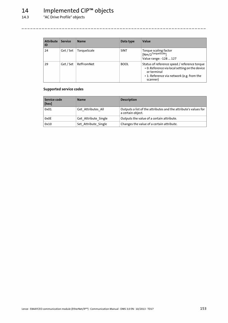
Lenze · E84AYCEO communication module (EtherNet/IP™) · Communication Manual · DMS 3.0 EN · 10/2013 · TD17 153
14 Implemented CIP™ objects14.3 "AC Drive Profile" objects
_ _ _ _ _ _ _ _ _ _ _ _ _ _ _ _ _ _ _ _ _ _ _ _ _ _ _ _ _ _ _ _ _ _ _ _ _ _ _ _ _ _ _ _ _ _ _ _ _ _ _ _ _ _ _ _ _ _ _ _ _ _ _ _
Supported service codes
24 Get / Set TorqueScale SINT Torque scaling factor[Nm/2TorqueScale]Value range: -128 ... 127
29 Get / Set RefFromNet BOOL Status of reference speed / reference torque• 0: Reference via local setting on the device
or terminal• 1: Reference via network (e.g. from the
scanner)
Service code[hex]
Name Description
0x01 Get_Attributes_All Outputs a list of the attributes and the attribute's values for a certain object.
0x0E Get_Attribute_Single Outputs the value of a certain attribute.
0x10 Set_Attribute_Single Changes the value of a certain attribute.
Attribute ID
Service Name Data type Value
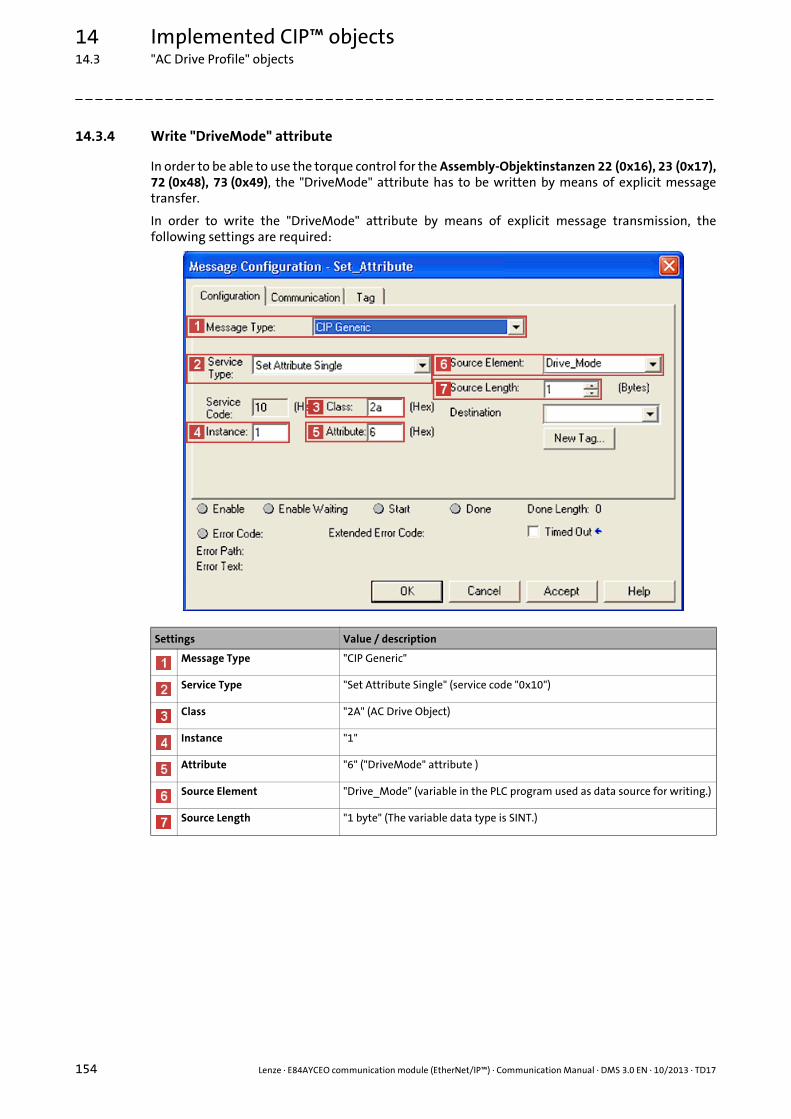
14 Implemented CIP™ objects14.3 "AC Drive Profile" objects
154 Lenze · E84AYCEO communication module (EtherNet/IP™) · Communication Manual · DMS 3.0 EN · 10/2013 · TD17
_ _ _ _ _ _ _ _ _ _ _ _ _ _ _ _ _ _ _ _ _ _ _ _ _ _ _ _ _ _ _ _ _ _ _ _ _ _ _ _ _ _ _ _ _ _ _ _ _ _ _ _ _ _ _ _ _ _ _ _ _ _ _ _
14.3.4 Write "DriveMode" attribute
In order to be able to use the torque control for the Assembly-Objektinstanzen 22 (0x16), 23 (0x17),72 (0x48), 73 (0x49), the "DriveMode" attribute has to be written by means of explicit messagetransfer.
In order to write the "DriveMode" attribute by means of explicit message transmission, thefollowing settings are required:
Settings Value / description
Message Type "CIP Generic"
Service Type "Set Attribute Single" (service code "0x10")
Class "2A" (AC Drive Object)
Instance "1"
Attribute "6" ("DriveMode" attribute )
Source Element "Drive_Mode" (variable in the PLC program used as data source for writing.)
Source Length "1 byte" (The variable data type is SINT.)

Lenze · E84AYCEO communication module (EtherNet/IP™) · Communication Manual · DMS 3.0 EN · 10/2013 · TD17 155
14 Implemented CIP™ objects14.4 Lenze objects
_ _ _ _ _ _ _ _ _ _ _ _ _ _ _ _ _ _ _ _ _ _ _ _ _ _ _ _ _ _ _ _ _ _ _ _ _ _ _ _ _ _ _ _ _ _ _ _ _ _ _ _ _ _ _ _ _ _ _ _ _ _ _ _
14.4 Lenze objects
14.4.1 Lenze Class (101 / 0x65)
The "Lenze Class (101 / 0x65)" enables the access to the adjustable error responses to EtherNet/IPerrors which can be set in code C13880.
Class attributes
Instance attributes
Note
The attributes of this class are described in the EDS file. Using the »RSNetWorx« Rockwell software, the attributes can thus be directly set under "Parameters" in the properties dialog of the EtherNet/IP node.
Attribute ID
Service Name Data type Value
1 Get Revision UINT 2 (0x0002)
2 Get Max. Instance UINT 1 (0x0001)
Attribute ID
Service Name Data type Value
1 Get No. of supported Attributes USINT 6 (0x0006)
2 Get Attribute List USINT 1 (0x0001) ... 6 (0x0006)
3 Get / Set Reaction on Idle Mode USINT Corresponds to the value in C13880/1:• 0 = no response• 1 = error• 4 = warning locked
4 Get / Set Reaction on Fault Mode USINT Corresponds to the value in C13880/2:• 0 = no response• 1 = error• 4 = warning locked
5 Get / Set Reaction on Expl. Msg. TO USINT Corresponds to the value in C13880/3:• 0 = no response• 1 = error• 4 = warning locked
6 Get / Set Reaction on I/O Timeout USINT Corresponds to the value in C13880/4:• 0 = no response• 1 = error• 4 = warning locked

14 Implemented CIP™ objects14.4 Lenze objects
156 Lenze · E84AYCEO communication module (EtherNet/IP™) · Communication Manual · DMS 3.0 EN · 10/2013 · TD17
_ _ _ _ _ _ _ _ _ _ _ _ _ _ _ _ _ _ _ _ _ _ _ _ _ _ _ _ _ _ _ _ _ _ _ _ _ _ _ _ _ _ _ _ _ _ _ _ _ _ _ _ _ _ _ _ _ _ _ _ _ _ _ _
Supported service codes
Service code[hex]
Name Description
0x01 Get_Attributes_All Outputs a list of the attributes and the attribute's values for a certain object.
0x0E Get_Attribute_Single Outputs the value of a certain attribute.
0x10 Set_Attribute_Single Changes the value of a certain attribute.

Lenze · E84AYCEO communication module (EtherNet/IP™) · Communication Manual · DMS 3.0 EN · 10/2013 · TD17 157
14 Implemented CIP™ objects14.4 Lenze objects
_ _ _ _ _ _ _ _ _ _ _ _ _ _ _ _ _ _ _ _ _ _ _ _ _ _ _ _ _ _ _ _ _ _ _ _ _ _ _ _ _ _ _ _ _ _ _ _ _ _ _ _ _ _ _ _ _ _ _ _ _ _ _ _
14.4.2 Lenze Class (103 / 0x67)
The "Lenze Class (103 / 0x67)" provides the image of the scanner input data.
The input data for the scanner are provided at the MCI_OUT interface of the communicationmodule and are sent to the scanner by means of the assembly object instance 111 (0xE6).
Class attributes
Instance attributes
Supported service codes
Attribute ID
Service Name Data type Value
1 Get Revision UINT 2 (0x0002)
2 Get Max. Instance UINT 1 (0x0001)
Attribute ID
Service Name Data type Value
1 Get No. of supported Attributes USINT 3 (0x0003)
2 Get Attribute List USINT 1 (0x0001) ... 3 (0x0003)
3 Get I/O image of produced data USINT Image of the scanner input data
Service code[hex]
Name Description
0x01 Get_Attributes_All Outputs a list of the attributes and the attribute's values for a certain object.
0x0E Get_Attribute_Single Outputs the value of a certain attribute.

14 Implemented CIP™ objects14.4 Lenze objects
158 Lenze · E84AYCEO communication module (EtherNet/IP™) · Communication Manual · DMS 3.0 EN · 10/2013 · TD17
_ _ _ _ _ _ _ _ _ _ _ _ _ _ _ _ _ _ _ _ _ _ _ _ _ _ _ _ _ _ _ _ _ _ _ _ _ _ _ _ _ _ _ _ _ _ _ _ _ _ _ _ _ _ _ _ _ _ _ _ _ _ _ _
14.4.3 Lenze Class (104 / 0x68)
The "Lenze Class (104 / 0x68)" provides the image of the scanner output data.
The output data of the scanner are sent by means of the assembly object instance 110 (0xE5,Custom Output) and are provided at the MCI_IN interface of the communication module.
Class attributes
Instance attributes
Supported service codes
Attribute ID
Service Name Data type Value
1 Get Revision UINT 2 (0x0002)
2 Get Max. Instance UINT 1 (0x0001)
Attribute ID
Service Name Data type Value
1 Get No. of supported Attributes USINT 3 (0x0003)
2 Get Attribute List USINT 1 (0x0001) ... 3 (0x0003)
3 Get I/O image of consumed data USINT Image of the scanner output data
Service code[hex]
Name Description
0x01 Get_Attributes_All Outputs a list of the attributes and the attribute's values for a certain object.
0x0E Get_Attribute_Single Outputs the value of a certain attribute.
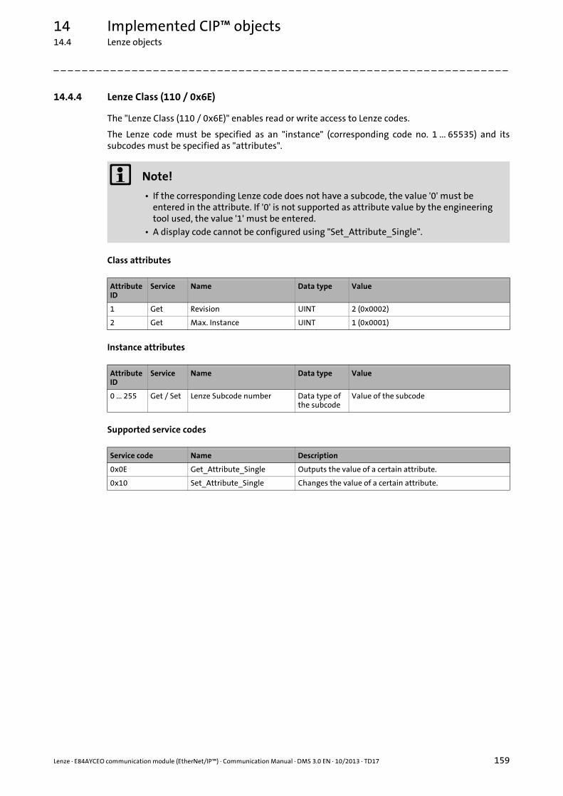
Lenze · E84AYCEO communication module (EtherNet/IP™) · Communication Manual · DMS 3.0 EN · 10/2013 · TD17 159
14 Implemented CIP™ objects14.4 Lenze objects
_ _ _ _ _ _ _ _ _ _ _ _ _ _ _ _ _ _ _ _ _ _ _ _ _ _ _ _ _ _ _ _ _ _ _ _ _ _ _ _ _ _ _ _ _ _ _ _ _ _ _ _ _ _ _ _ _ _ _ _ _ _ _ _
14.4.4 Lenze Class (110 / 0x6E)
The "Lenze Class (110 / 0x6E)" enables read or write access to Lenze codes.
The Lenze code must be specified as an "instance" (corresponding code no. 1 ... 65535) and itssubcodes must be specified as "attributes".
Class attributes
Instance attributes
Supported service codes
Note!
• If the corresponding Lenze code does not have a subcode, the value '0' must be entered in the attribute. If '0' is not supported as attribute value by the engineering tool used, the value '1' must be entered.
• A display code cannot be configured using "Set_Attribute_Single".
Attribute ID
Service Name Data type Value
1 Get Revision UINT 2 (0x0002)
2 Get Max. Instance UINT 1 (0x0001)
Attribute ID
Service Name Data type Value
0 ... 255 Get / Set Lenze Subcode number Data type of the subcode
Value of the subcode
Service code Name Description
0x0E Get_Attribute_Single Outputs the value of a certain attribute.
0x10 Set_Attribute_Single Changes the value of a certain attribute.
Index
160 Lenze · E84AYCEO communication module (EtherNet/IP™) · Communication Manual · DMS 3.0 EN · 10/2013 · TD17
_ _ _ _ _ _ _ _ _ _ _ _ _ _ _ _ _ _ _ _ _ _ _ _ _ _ _ _ _ _ _ _ _ _ _ _ _ _ _ _ _ _ _ _ _ _ _ _ _ _ _ _ _ _ _ _ _ _ _ _ _ _ _ _
AAC Drive Object (42 / 0x2A) 152
AC drive profile objects 148
AC Drive Profile technology application 59
Activating changed setting 51
Active Conflict Detection State (C13847) 113
Active gateway address (C13012) 109
Active IP address (C13010) 108
Active Multicast IP Address (C13016) 109
Active subnetwork mask (C13011) 108
Address Conflict Detection (C13846) 113
All words from scanner (C13851) 115
All words to scanner (C13850) 114
All words to the basic device (C13852) 115
All words to the basic device (C13853) 115
Application as directed 13
Application notes 10
Approvals 16
ARP message 144
Assemblies 60
Assembly input objects (adapter to scanner) 61
Assembly Object (4 / 0x04) 129
Assembly output objects (scanner to adapter) 61
BBaud rate 16
Beacon Frames (C13845) 113
Beacon Times (C13844) 113
Before initial switch-on 35
BOOTP server 47
CC13000 | IP Address 106
C13001 | Subnetwork mask 106
C13002 | Gateway Address 107
C13003 | MAC ID 107
C13005 | IP Config Control 107
C13006 | Multicast IP Start Address 108
C13010 | Active IP address 108
C13011 | Active Subnetwork Mask 108
C13012 | Active gateway address 109
C13016 | Active Multicast IP Address 109
C13017 | Ethernet Config Control 110
C13018 | Multicast Config Alloc Control 110
C13019 | Multicast Config TTL Value 110
C13020 | Multicast Config Num Mcast 111
C13021 | Quality of Service (VLAN-Tagging) 111
C13022 | Quality of Service (DSCP) 111
C13840 | DLR Network Topology 112
C13841 | DLR Network Status 112
C13842 | Supervisor IP Address 112
C13843 | Supervisor MAC ID 112
C13844 | Beacon Times 113
C13845 | Beacon Frames 113
C13846 | Address Conflict Detection 113
C13847 | Active Conflict Detection State 113
C13848 | Last Conflicted MAC ID 114
C13849 | Last Conflicted IP Address 114
C13850 | All words to scanner 114
C13851 | All words from scanner 115
C13852 | All words to the basic device 115
C13853 | All words to the basic device 115
C13858 | Ethernet Port Statistics 116
C13861 | CIP Module Status 116
C13862 | CIP Network Status 117
C13863 | Ethernet Port 117
C13870 | CIP Connections State 117
C13871 | CIP Connections Type 118
C13872 | CIP Connection Triggers 118
C13873 | CIP Connections RPI 118
C13874 | CIP Connections Timeout Time 119
C13875 | CIP Connections RUN/IDLE Flag 119
C13880 | Monitoring Reaction 119
C13881 | Overall Ethernet Timeout Time 120
C13885 | Clear I/O Data 120
C13899 | Hostname 120
C13900 | Firmware product type 120
C13901 | Firmware compilation date 120
C13902 | Firmware version 121
C13920 | Rotary coding switch: xxx.yyy.zzz.DDD 121
Cable length 16
CIP Connection Triggers (C13872) 118
CIP Connections RPI (C13873) 118
CIP Connections RUN/IDLE Flag (C13875) 119
CIP Connections State (C13870) 117
CIP Connections Timeout Time (C13874) 119
CIP Connections Type (C13871) 118
CIP error messages 101
CIP Module Status (C13861) 116
CIP Network Status (C13862) 117
CIP objects 124
CIP status indicators 91
Class attributes 125
Clear I/O Data (C13885) 120
Codes 106
Colour code of the Ethernet cable 32
Commissioning 35
Communication channels 53
Communication medium 16
Communication profile 16
Communication time 20
Configuring "AC Drive Profile" technology application 67
Configuring AC Drive Profile application 67
Configuring Lenze technology applications 62
Configuring the host system (scanner) 36
Configuring the scanner 36
Index

Lenze · E84AYCEO communication module (EtherNet/IP™) · Communication Manual · DMS 3.0 EN · 10/2013 · TD17 161
Index
_ _ _ _ _ _ _ _ _ _ _ _ _ _ _ _ _ _ _ _ _ _ _ _ _ _ _ _ _ _ _ _ _ _ _ _ _ _ _ _ _ _ _ _ _ _ _ _ _ _ _ _ _ _ _ _ _ _ _ _ _ _ _ _
Configuring user-definable parameter sets 62
Conformities 16
Connection Manager Object (6 / 0x06) 135
Connections 15
Control Supervisor Object (41 / 0x29) 150
Conventions 8
Conventions used 8
Cyclic I/O data 54
DData mapping of the input assemblies 133
Data mapping of the output assemblies 133
Data transfer 52
Device and application-specific safety instructions 12
Device Level Ring (DLR) Object (71 / 0x47) 137
Device protection 12
Device type 16
DHCP server 47
Diagnostics 89
Diagnostics with the »Engineer« 95
Dimensions 22
DLR Network Status (C13841) 112
DLR Network Topology (C13840) 112
Document history 7
Drive profiles 58
DRIVECOM error 102
EEDS files 37
Electrical installation 27
E-mail to Lenze 164
Error messages 96Causes and remedies 97Short overview 96
Error messages of the "Connection Manager Object" (0x06) 136
Error number0x01bc3100 970x01bc5531 970x01bc5532 970x01bc5533 970x01bc6010 970x01bc6011 980x01bc6100 980x01bc6101 980x01bc641f 980x01bc6420 980x01bc6430 980x01bc6533 990x01bc8111 990x01bc8112 990x01bc8114 990x01bc8121 990x01bc8132 1000x01bc8273 100
Establishing an online connection via EtherNet/IP using the Lenze »Engineer« 49
Establishing communication 51
Ethernet cable 31
Ethernet cable specification 31
Ethernet cable, colour code 32
Ethernet cable, structure 31
Ethernet Config Control (C13017) 110
Ethernet Link Object (246 / 0xF6) 145
Ethernet Port (C13863) 117
Ethernet Port Statistics (C13858) 116
EtherNet/IPDuplicate IP Address (error message) 100Error: Lenze Setting Loaded (error message) 98Ethernet cable pulled out (error message) 99Exist. connect. to 8400 lost (error message) 97Explicit Message Timeout (error message) 99Fault Mode (error message) 99Idle Mode (error message) 100Internal error (error message) 98Invalid Configuration (error message) 98Invalid IP Parameter (error message) 99Invalid Parameter Set (error message) 98Memory
No Access (error message) 97Read Error (error message) 97Write Error (error message) 97
Overall Ethernet Timeout (error message) 99Restart by Watchdogreset (error message) 97
EtherNet/IP connection 29
EtherNet/IP error messages: Causes and remedies 97
EtherNet/IP objects 137
EtherNet/IP state diagram 55
Explicit messages 84
Explicit messages (parameter data transfer) 54
External voltage supply 33
FFault with regard to EtherNet/IP communication 88
Feedback to Lenze 164
Firmware Compilation Date (C13901) 120
Firmware Product Type (C13900) 120
Firmware Version (C13902) 121
GGateway address 46
Gateway Address (C13002) 107
General data 16
General safety and application notes 11

Index
162 Lenze · E84AYCEO communication module (EtherNet/IP™) · Communication Manual · DMS 3.0 EN · 10/2013 · TD17
_ _ _ _ _ _ _ _ _ _ _ _ _ _ _ _ _ _ _ _ _ _ _ _ _ _ _ _ _ _ _ _ _ _ _ _ _ _ _ _ _ _ _ _ _ _ _ _ _ _ _ _ _ _ _ _ _ _ _ _ _ _ _ _
HHostname (C13899) 120
II/O assemblies 60
I/O configuration in the »Engineer« 62
I/O configuration with »RSLogix 5000« version 19 or lower 68
I/O configuration with »RSLogix 5000« version 20 or higher 73
I/O data mapping 57
I/O data transfer (implicit messages) 56
Identification 13
Identity Object (1 / 0x01) 126
Implicit messages 56
Implicit messages (I/O data transfer) 54
Information regarding the validity 6
Initial switch-on 51
Input assemblies 60
Input assemblies data mapping 133
Installation 23
Interface for communication 16
Interfaces 15
Internal switch latency 21
IP address 46
IP address (C13000) 106
IP Config Control (C13005) 107
LLast Conflicted IP Address (C13849) 114
Last Conflicted MAC ID (C13848) 114
Layout of the safety instructions 10
LED status displays 89
Lenze Class (101 / 0x65) 155
Lenze Class (103 / 0x67) 157
Lenze Class (104 / 0x68) 158
Lenze Class (110 / 0x6E) 159
Lenze objects 155
Lenze technology application 58
MMAC-ID (C13003) 107
Mapping of Lenze device errors to DRIVECOM errors 102
Mechanical installation 24
Message Router Object (2 / 0x02) 128
Module status displays 90
Monitoring 88
Monitoring Reaction (C13880) 119
Motor Data Object (40 / 0x28) 149
Mounting for standard devices of 0.25 kW and 0.37 kW 24
Mounting for standard devices of 0.55 kW or more 25
Multicast Config Alloc Control (C13018) 110
Multicast Config Num Mcast (C13020) 111
Multicast Config TTL Value (C13019) 110
Multicast configuration 48
Multicast IP Start Address 48
Multicast IP Start Address (C13006) 108
NNameplate 13
Network topology 16, 27
Number of nodes 16
OOperating conditions 16
Output assemblies 60
Output assemblies data mapping 133
Overall Ethernet Timeout Time (C13881) 120
PParameter data transfer (explicit messages) 84
Parameter reference 106
Parameters of the communication module 106
Pin assignment of the RJ45 sockets 30
Processing time 20
Product code 16
Product description 13
Product features 14
Protection against uncontrolled restart 51
Protection of persons 12
Protective insulation 17
Protocol data 20
QQuality of Service (DSCP, C13022) 111
Quality of Service (QoS) Object (72 / 0x48) 139
Quality of Service (VLAN Tagging, C13021) 111
RRead parameters 86
Replacing the communication module 26
Residual hazards 12
Rotary coding switch: xxx.yyy.zzz.DDD (C13920) 121
Rotary coding switches 40
Runtime delays 21

Lenze · E84AYCEO communication module (EtherNet/IP™) · Communication Manual · DMS 3.0 EN · 10/2013 · TD17 163
Index
_ _ _ _ _ _ _ _ _ _ _ _ _ _ _ _ _ _ _ _ _ _ _ _ _ _ _ _ _ _ _ _ _ _ _ _ _ _ _ _ _ _ _ _ _ _ _ _ _ _ _ _ _ _ _ _ _ _ _ _ _ _ _ _
SSafety instructions 10, 11
Saving the I/O configuration in »RSLogix 5000« 83
Screenshots/application examples 6
Setting the IP configuration 42
Setting via the EtherNet/IP configurator of the »Engineer« 43
Short overview of EtherNet/IP error messages 96
State diagram 55
Status displays (LEDs) 89
Status indicators at the RJ45 sockets (X259, X260) 94
Structure of the Ethernet cable 31
Subnet mask 46
Subnetwork mask (C13001) 106
Supervisor IP Address (C13842) 112
Supervisor MAC ID (C13843) 112
Switch latency 16, 21
Switching method 16
System error messages 96
TTable of attributes 122
Target group 6
TCP/IP Interface Object 47
TCP/IP Interface Object (245 / 0xF5) 141
Technical data 16
Technology applications (TA) 58
Telegram types 54
Terminals 34
Terminology used 9
Terms 9
Transmission mode 16
Type of node 16
UUser-definable parameter sets 58
Using the communication module 13
VVendor ID 16
VLAN tagging 139
Voltage supply 16, 33
WWiring according to EMC guidelines 27
Write "DriveMode" attribute 154
Write DriveMode (attribute ID 6) 154
Write parameters 85

164
Your opinion is important to usThese instructions were created to the best of our knowledge andbelief to give you the best possible support for handling our product.
If you have suggestions for improvement, please e-mail us to:
Thank you for your support.
Your Lenze documentation team

L
E84AYCEO communication module (EtherNet/IP™) · Communication Manual · EDS84AYCEO · 13443009 · DMS 3.0 EN · 10/2013 · TD17
Lenze Drives GmbHPostfach 10 13 52D-31763 HamelnGermany
+49 (0)51 54 / 82-0+49 (0)51 54 / 82-28 [email protected]
ServiceLenze Service GmbHBreslauer Straße 3D-32699 ExtertalGermany
00 80 00 / 24 4 68 77 (24 h helpline)+49 (0)51 54 / 82-11 [email protected]