Communication Capabilities via a Touch Screen or a Web … Brochure - PCITUSE08 … ·...
8
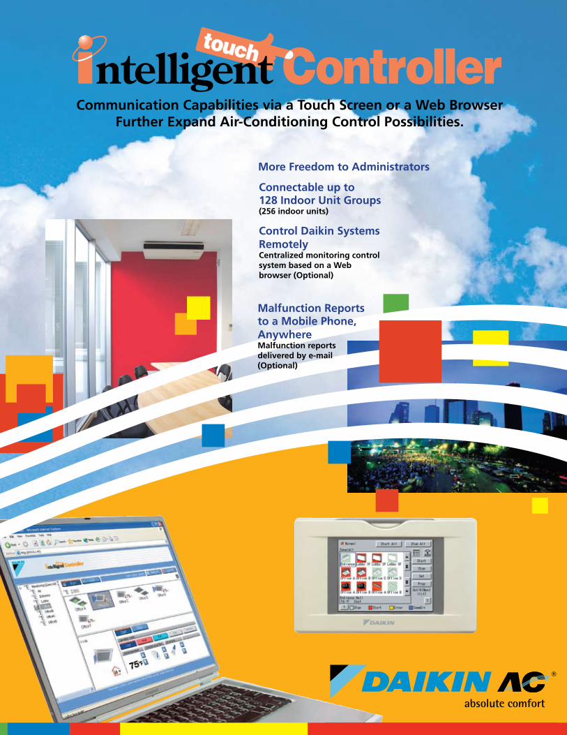
Communication Capabilities via a Touch Screen or a Web Browser Further Expand Air-Conditioning Control Possibilities. More Freedom to Administrators Malfunction Reports to a Mobile Phone, Anywhere Malfunction reports delivered by e-mail (Optional) Connectable up to 128 Indoor Unit Groups (256 indoor units) Control Daikin Systems Remotely Centralized monitoring control system based on a Web browser (Optional)
Transcript of Communication Capabilities via a Touch Screen or a Web … Brochure - PCITUSE08 … ·...
© 2008 Daikin Industries, Limited.
Daikin®, Daikin® AC are trademarks pending or registered trademarks of Daikin Industries, Limited. All rights reserved.
– Daikin’s products are subject to continuous improvements. Daikin reserves the right to modify product design, specifications and information in this brochure without notice and without incurring any obligations.* The Power Proportional Distribution (PPD) feature supplies the user with a reasonably calculated apportionment of the total power consumption by the Daikin air-conditioning system to individual units on the system. Because input to the
PPD includes measured pulses in the refrigerant system and because the air-conditioning system includes a number of variables, including operating temperatures and pressures, piping length, heat exchange rates and others, no meter-type apportionment of individual users’ consumption can be made. However, the PPD feature provides an apportionment methodology that uses highly advanced technology as applied to the many variables in an air-conditioning system.
PCITUSE08-09C
Daikin AC (Americas), Inc. 1645 Wallace Drive, Suite 110
Carrollton, TX 75006 [email protected]
866-4DAIKIN (972) 245-1510
Dealer Information
Communication Capabilities via a Touch Screen or a Web Browser Further Expand Air-Conditioning Control Possibilities.
More Freedom to Administrators
Malfunction Reportsto a Mobile Phone, AnywhereMalfunction reportsdelivered by e-mail(Optional)
Connectable up to128 Indoor Unit Groups(256 indoor units)
Control Daikin SystemsRemotelyCentralized monitoring controlsystem based on a Webbrowser (Optional)
The air conditioners manufactured by Daikin Industries have received ISO 9000 series certification for quality assurance.
Certificate Numbers: (ISO9001) JMI-0107 (ISO9002) JQA-1452 JQA-1452
All Daikin Industries locations and subsidiaries in Japan have received environmental management system standard ISO 14001 certification.
Daikin Industries, Ltd.Domestic GroupCertificate Number: EC99J2044
ISO 14001 is the standard defined by the International Organization for Standardization (ISO) relating to environmental management systems. Our group has been acknowledged by an internationally accredited compliance organization as having an appropriate program of environmental protection procedures and activities to meet the requirements of ISO 14001.
About ISO 14001
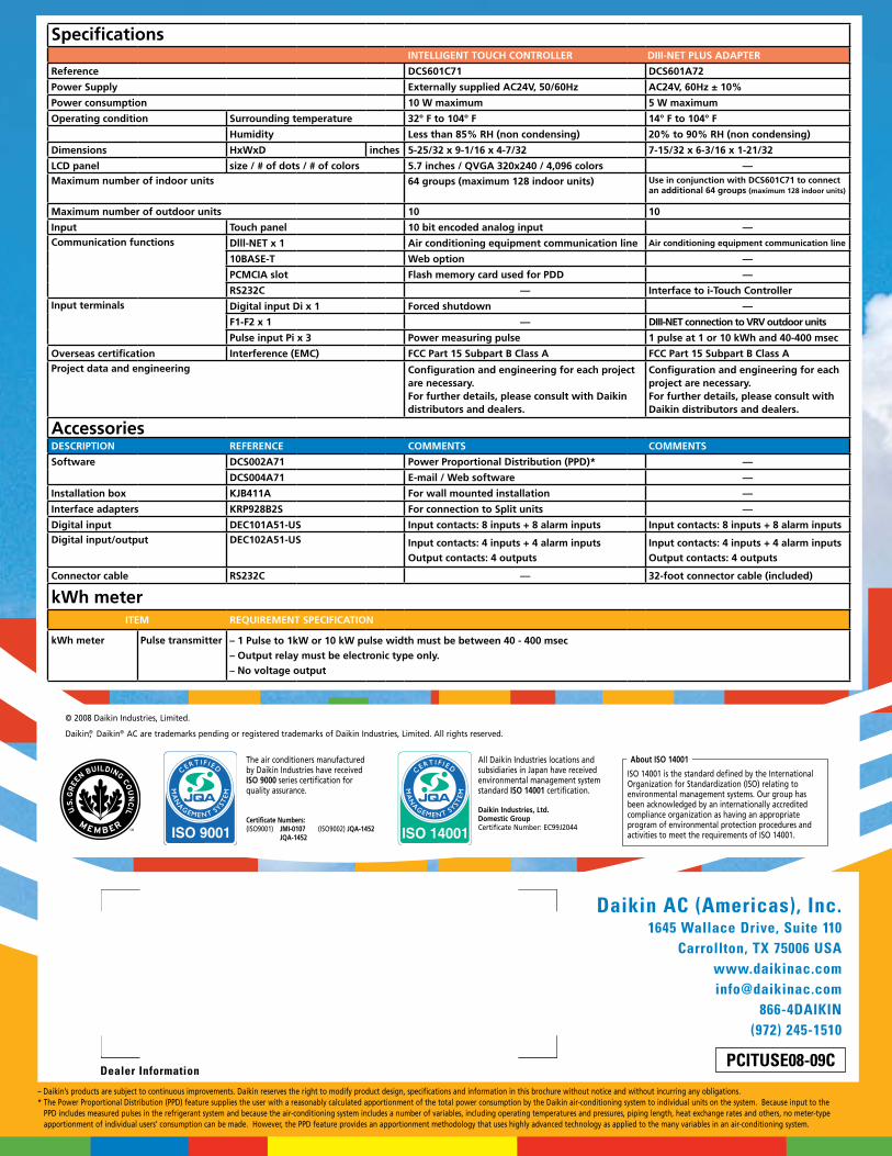
SpecificationsINTELLIGENT TOUCH CONTROLLER DIII-NET PLUS ADAPTER
Reference DCS601C71 DCS601A72
Power Supply Externally supplied AC24V, 50/60Hz AC24V, 60Hz ± 10%
Power consumption 10 W maximum 5 W maximum
Operating condition Surrounding temperature 32° F to 104° F 14° F to 104° F
Humidity Less than 85% RH (non condensing) 20% to 90% RH (non condensing)
Dimensions HxWxD inches 5-25/32 x 9-1/16 x 4-7/32 7-15/32 x 6-3/16 x 1-21/32
LCD panel size / # of dots / # of colors 5.7 inches / QVGA 320x240 / 4,096 colors —Maximum number of indoor units 64 groups (maximum 128 indoor units) Use in conjunction with DCS601C71 to connect
an additional 64 groups (maximum 128 indoor units)
Maximum number of outdoor units 10 10
Input Touch panel 10 bit encoded analog input —Communication functions Dlll-NET x 1 Air conditioning equipment communication line Air conditioning equipment communication line
10BASE-T Web option —
PCMCIA slot Flash memory card used for PDD —
RS232C — Interface to i-Touch ControllerInput terminals Digital input Di x 1 Forced shutdown —
F1-F2 x 1 — DIII-NET connection to VRV outdoor units
Pulse input Pi x 3 Power measuring pulse 1 pulse at 1 or 10 kWh and 40-400 msec
Overseas certification Interference (EMC) FCC Part 15 Subpart B Class A FCC Part 15 Subpart B Class AProject data and engineering Configuration and engineering for each project
are necessary. For further details, please consult with Daikin distributors and dealers.
Configuration and engineering for each project are necessary. For further details, please consult with Daikin distributors and dealers.
AccessoriesDESCRIPTION REFERENCE COMMENTS COMMENTS
Software DCS002A71 Power Proportional Distribution (PPD)* —
DCS004A71 E-mail / Web software —
Installation box KJB411A For wall mounted installation —
Interface adapters KRP928B2S For connection to Split units —
Digital input DEC101A51-US Input contacts: 8 inputs + 8 alarm inputs Input contacts: 8 inputs + 8 alarm inputsDigital input/output DEC102A51-US Input contacts: 4 inputs + 4 alarm inputs
Output contacts: 4 outputsInput contacts: 4 inputs + 4 alarm inputsOutput contacts: 4 outputs
Connector cable RS232C — 32-foot connector cable (included)
kWh meterITEM REQUIREMENT SPECIFICATION
kWh meter Pulse transmitter – 1 Pulse to 1kW or 10 kW pulse width must be between 40 - 400 msec– Output relay must be electronic type only. – No voltage output
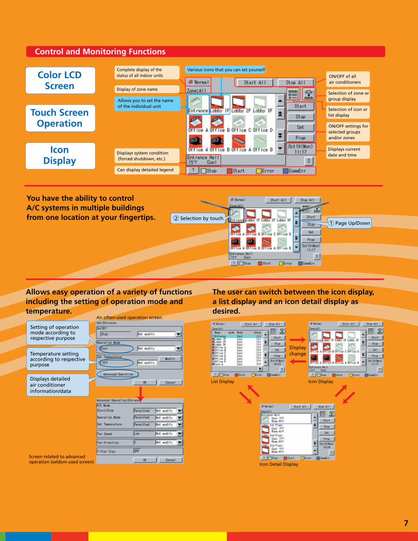
Control and Monitoring Functions
With just two or three simple actions, you can specify the air conditioner you want and control it with the utmost speed.
Icon Display
Displaychange
List Display
Selection of icon orlist display
Selection of zone orgroup display
ON/OFF settings for selected groups and/or zones
Complete display of the status of all air conditioners
Display of zone name
Various icons that you can set yourself
Displays current date and timeDisplays system condition
(forced shutdown, etc.)
Can display detailed legend
Allows you to set the name of the individual unit
Allows easy operation of a variety of functionsincluding the setting of operation mode andtemperature.
The user can switch between the icon display, a list display and an icon detail display as desired.
Setting of operation mode according to respective purpose
Temperature setting according to respective purpose
Displays detailed air conditioner information/data
Screen related to advanced operation (seldom-used screen)
An often-used operation screen
ON/OFF of all air conditioners
Color LCDScreen
Touch ScreenOperation
IconDisplay
2 Selection by touch1 Page Up/Down
Icon Detail Display
7
Control and Monitoring Functions
°F
CoolingSet Point
HeatingSet Point
Heating
Heating
Cooling
HeatingCooling
Heating
Time
Cooling
Temp Difference Change Set Point
Change Set Point
It is possible to set up an automated yearly schedule specifying such items as daily startup and shutoff times, temperature settings and operation modes. In addition, the number of patterns that can be registered has been increased from seven to 10.
The color of the icons indicating running and stopped status can be changed. This makes it easy to customize the display to match the administrator’s preferences or match the display of other control devices.
The simple interlock function allows for controlling of multiple groups and zones based on the operation status of the selected groups or zones.
The error history function keeps a detailed record broken down by malfunction item. This is an important feature for maintaining the system and dealing with malfunctions, and it helps ensure that appropriate maintenance work is performed.
Automatic cooling/heating changeover maintains optimum room temperature by indoor unit groups (auto changeover group) subject to large temperature difference between night and day.
-5°F — 13°F deadband
Passwords for general user and for administrators can be registered separately, permitting access to different levels of control functions
Enhanced display and ease of use, plus expanded control functions.
Input (Lights)
Input (Key signal)
DIO UnitDEC102A51-US
DIO UnitDEC102A51-US
Set temperature change command
OFF command
6
Calendar Screen
Enhanced Scheduling Function Changing Display Colors
Simple Interlock Function Added Enhanced History Function
SecurityAuto Heat/Cool Changeover
The user-friendly controller already features colors
and icons in the display for ease of understanding.
A wide variety of control methods enables
administrators to monitor and operate the system
even when they are away from the controller.
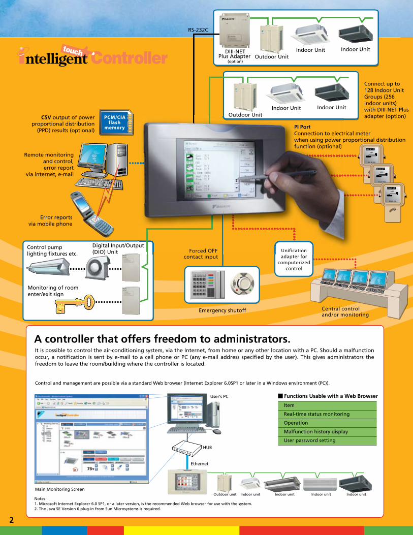
Control and management are possible via a standard Web browser (Internet Explorer 6.0SP1 or later in a Windows environment (PC)).
Main Monitoring Screen
User’s PC
HUB
Ethernet
A controller that offers freedom to administrators. It is possible to control the air-conditioning system, via the Internet, from home or any other location with a PC. Should a malfunction occur, a notification is sent by e-mail to a cell phone or PC (any e-mail address specified by the user). This gives administrators the freedom to leave the room/building where the controller is located.
Notes1. Microsoft Internet Explorer 6.0 SP1, or a later version, is the recommended Web browser for use with the system.2. The Java SE Version 6 plug-in from Sun Microsystems is required.
Item
Real-time status monitoring
Operation
Malfunction history display
User password setting
Functions Usable with a Web Browser
2
Control pump, lighting etc.
Monitoring of roomenter/exit sign
Input (Lights)
Input (Lights)
Max 8 point
Output (Indoor units)
Output
Input (Key signal)
Input (Key signal –general-purpose ADP)
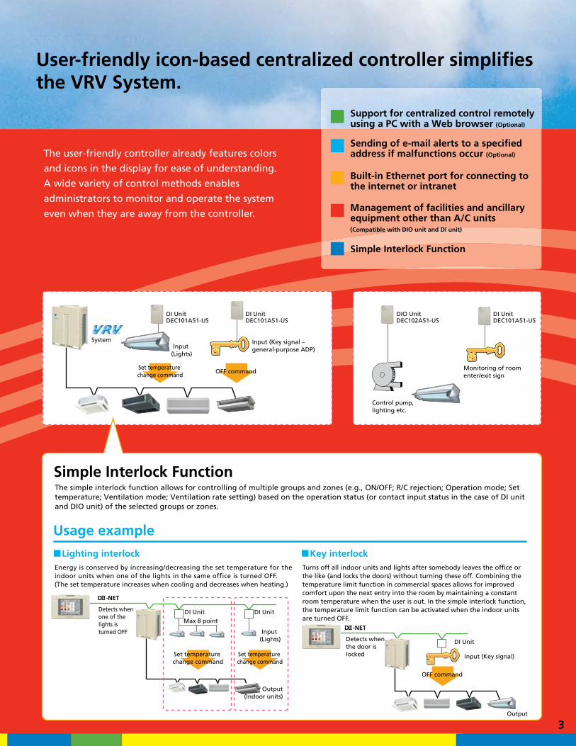
Simple Interlock FunctionThe simple interlock function allows for controlling of multiple groups and zones (e.g., ON/OFF; R/C rejection; Operation mode; Set temperature; Ventilation mode; Ventilation rate setting) based on the operation status (or contact input status in the case of DI unit and DIO unit) of the selected groups or zones.
Usage example
DI UnitDEC101A51-US
DI UnitDEC101A51-US
DIO UnitDEC102A51-US
DI UnitDEC101A51-US
DI Unit DI Unit
D -NET
System
Energy is conserved by increasing/decreasing the set temperature for the indoor units when one of the lights in the same office is turned OFF. (The set temperature increases when cooling and decreases when heating.)
Turns off all indoor units and lights after somebody leaves the office or the like (and locks the doors) without turning these off. Combining the temperature limit function in commercial spaces allows for improved comfort upon the next entry into the room by maintaining a constant room temperature when the user is out. In the simple interlock function, the temperature limit function can be activated when the indoor units are turned OFF.
D -NET
Lighting interlock Key interlock
Detects when the door is locked
Detects when one of the lights is turned OFF
Set temperature change command
Set temperature change command
Set temperature change command
OFF command
OFF command
3
User-friendly icon-based centralized controller simplifiesthe VRV System.
Support for centralized control remotely using a PC with a Web browser (Optional)
Sending of e-mail alerts to a specified address if malfunctions occur (Optional)
Built-in Ethernet port for connecting to the internet or intranet
Management of facilities and ancillary equipment other than A/C units(Compatible with DIO unit and DI unit)
Simple Interlock Function
Indoor unitOutdoor unit Indoor unit Indoor unit Indoor unit
DI Unit
Indoor Unit Indoor Unit
Indoor Unit Indoor Unit
RS-232C
DIII-NETPlus Adapter
(option)Outdoor Unit
Outdoor Unit
Error reportsvia mobile phone
Central controland/or monitoring
Forced OFFcontact input
Unificationadapter for
computerizedcontrol
PCM/CIAflash
memory
Connect up to 128 Indoor UnitGroups (256 indoor units)with DIII-NET Plusadapter (option)
PI PortConnection to electrical meterwhen using power proportional distributionfunction (optional)
CSV output of powerproportional distribution
(PPD) results (optional)
Control pumplighting fixtures etc.
Digital Input/Output (DIO) Unit
Monitoring of roomenter/exit sign
Remote monitoringand control,error report
via internet, e-mail
Emergency shutoff
rical propo
puUnificationForced OFF
Outdoor UnitOutdoor Unit
Forced OFF Unification
PI PortConnection to electrwhen using power pfunction (optional)
ut
Control and Monitoring Functions
With just two or three simple actions, you can specify the air conditioner you want and control it with the utmost speed.
Icon Display
Displaychange
List Display
Selection of icon orlist display
Selection of zone orgroup display
ON/OFF settings for selected groups and/or zones
Complete display of the status of all air conditioners
Display of zone name
Various icons that you can set yourself
Displays current date and timeDisplays system condition
(forced shutdown, etc.)
Can display detailed legend
Allows you to set the name of the individual unit
Allows easy operation of a variety of functionsincluding the setting of operation mode andtemperature.
The user can switch between the icon display, a list display and an icon detail display as desired.
Setting of operation mode according to respective purpose
Temperature setting according to respective purpose
Displays detailed air conditioner information/data
Screen related to advanced operation (seldom-used screen)
An often-used operation screen
ON/OFF of all air conditioners
Color LCDScreen
Touch ScreenOperation
IconDisplay
2 Selection by touch1 Page Up/Down
Icon Detail Display
7
Control and Monitoring Functions
°F
CoolingSet Point
HeatingSet Point
Heating
Heating
Cooling
HeatingCooling
Heating
Time
Cooling
Temp Difference Change Set Point
Change Set Point
It is possible to set up an automated yearly schedule specifying such items as daily startup and shutoff times, temperature settings and operation modes. In addition, the number of patterns that can be registered has been increased from seven to 10.
The color of the icons indicating running and stopped status can be changed. This makes it easy to customize the display to match the administrator’s preferences or match the display of other control devices.
The simple interlock function allows for controlling of multiple groups and zones based on the operation status of the selected groups or zones.
The error history function keeps a detailed record broken down by malfunction item. This is an important feature for maintaining the system and dealing with malfunctions, and it helps ensure that appropriate maintenance work is performed.
Automatic cooling/heating changeover maintains optimum room temperature by indoor unit groups (auto changeover group) subject to large temperature difference between night and day.
-5°F — 13°F deadband
Passwords for general user and for administrators can be registered separately, permitting access to different levels of control functions
Enhanced display and ease of use, plus expanded control functions.
Input (Lights)
Input (Key signal)
DIO UnitDEC102A51-US
DIO UnitDEC102A51-US
Set temperature change command
OFF command
6
Calendar Screen
Enhanced Scheduling Function Changing Display Colors
Simple Interlock Function Added Enhanced History Function
SecurityAuto Heat/Cool Changeover
The user-friendly controller already features colors
and icons in the display for ease of understanding.
A wide variety of control methods enables
administrators to monitor and operate the system
even when they are away from the controller.
Control and management are possible via a standard Web browser (Internet Explorer 6.0SP1 or later in a Windows environment (PC)).
Main Monitoring Screen
User’s PC
HUB
Ethernet
A controller that offers freedom to administrators. It is possible to control the air-conditioning system, via the Internet, from home or any other location with a PC. Should a malfunction occur, a notification is sent by e-mail to a cell phone or PC (any e-mail address specified by the user). This gives administrators the freedom to leave the room/building where the controller is located.
Notes1. Microsoft Internet Explorer 6.0 SP1, or a later version, is the recommended Web browser for use with the system.2. The Java SE Version 6 plug-in from Sun Microsystems is required.
Item
Real-time status monitoring
Operation
Malfunction history display
User password setting
Functions Usable with a Web Browser
2
Control pump, lighting etc.
Monitoring of roomenter/exit sign
Input (Lights)
Input (Lights)
Max 8 point
Output (Indoor units)
Output
Input (Key signal)
Input (Key signal –general-purpose ADP)
Simple Interlock FunctionThe simple interlock function allows for controlling of multiple groups and zones (e.g., ON/OFF; R/C rejection; Operation mode; Set temperature; Ventilation mode; Ventilation rate setting) based on the operation status (or contact input status in the case of DI unit and DIO unit) of the selected groups or zones.
Usage example
DI UnitDEC101A51-US
DI UnitDEC101A51-US
DIO UnitDEC102A51-US
DI UnitDEC101A51-US
DI Unit DI Unit
D -NET
System
Energy is conserved by increasing/decreasing the set temperature for the indoor units when one of the lights in the same office is turned OFF. (The set temperature increases when cooling and decreases when heating.)
Turns off all indoor units and lights after somebody leaves the office or the like (and locks the doors) without turning these off. Combining the temperature limit function in commercial spaces allows for improved comfort upon the next entry into the room by maintaining a constant room temperature when the user is out. In the simple interlock function, the temperature limit function can be activated when the indoor units are turned OFF.
D -NET
Lighting interlock Key interlock
Detects when the door is locked
Detects when one of the lights is turned OFF
Set temperature change command
Set temperature change command
Set temperature change command
OFF command
OFF command
3
User-friendly icon-based centralized controller simplifiesthe VRV System.
Support for centralized control remotely using a PC with a Web browser (Optional)
Sending of e-mail alerts to a specified address if malfunctions occur (Optional)
Built-in Ethernet port for connecting to the internet or intranet
Management of facilities and ancillary equipment other than A/C units(Compatible with DIO unit and DI unit)
Simple Interlock Function
Indoor unitOutdoor unit Indoor unit Indoor unit Indoor unit
DI Unit
Indoor Unit Indoor Unit
Indoor Unit Indoor Unit
RS-232C
DIII-NETPlus Adapter
(option)Outdoor Unit
Outdoor Unit
Error reportsvia mobile phone
Central controland/or monitoring
Forced OFFcontact input
Unificationadapter for
computerizedcontrol
PCM/CIAflash
memory
Connect up to 128 Indoor UnitGroups (256 indoor units)with DIII-NET Plusadapter (option)
PI PortConnection to electrical meterwhen using power proportional distributionfunction (optional)
CSV output of powerproportional distribution
(PPD) results (optional)
Control pumplighting fixtures etc.
Digital Input/Output (DIO) Unit
Monitoring of roomenter/exit sign
Remote monitoringand control,error report
via internet, e-mail
Emergency shutoff
rical propo
puUnificationForced OFF
Outdoor UnitOutdoor Unit
Forced OFF Unification
PI PortConnection to electrwhen using power pfunction (optional)
ut
Remote Monitoring of Multiple PropertiesAccessing intelligent Touch Controller from a Remote Location
Accessing intelligent Touch Controller via the Internet
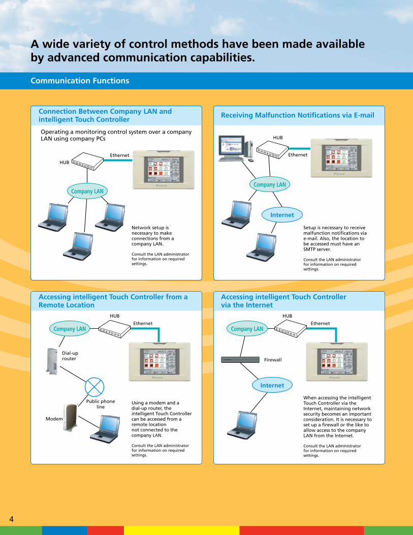
A wide variety of control methods have been made available by advanced communication capabilities.
HUB
Ethernet
HUB
Ethernet
Operating a monitoring control system over a company LAN using company PCs
It is possible to specify the scope of monitoring control system functions on a per-user basis.
Company LAN
Network setup is necessary to make connections from a company LAN.
Consult the LAN administrator for information on required settings.
Company LAN
Internet
Setup is necessary to receive malfunction notifications via e-mail. Also, the location to be accessed must have an SMTP server.
Consult the LAN administrator for information on required settings.
HUB
Dial-up router
Modem
EthernetCompany LAN
Using a modem and a dial-up router, the intelligent Touch Controller can be accessed from a remote location not connected to the company LAN.
Consult the LAN administrator for information on required settings.
HUB
Firewall
EthernetCompany LAN
Internet
When accessing the intelligent Touch Controller via the Internet, maintaining network security becomes an important consideration. It is necessary to set up a firewall or the like to allow access to the company LAN from the Internet.
Consult the LAN administrator for information on required settings.
Note:The following items need to be set up, managed and operated by yourself.
1. SecurityAn environment that satisfies your security policy.
2. NetworkEquipment and settings that suit your network environment. A network security device such as a firewall, which is necessary when connecting via the Internet.
Using an Internet connection, multiple properties can be controlled from a single location.
Screen of user’s PC on fourth floor
Only the air conditioning units on the fourth floor are displayed. The user cannot monitor or control other users’ air-conditioning systems.
Notes1. The maximum number of registered users is 65
for web function, consisting of 64 general users and 1 administrator.
2. Display language settings can be customized for each user.
3. Only administrators can make schedule settings.
Screen of administrator Users can stay in touch.
Internet*
Allowing Individual Tenants to Operate the Air-Conditioning System from their PCs
Ability to Control Air-Conditioning Systems in Multiple Buildings from a Central Location Forexample…
Communication Functions
Public phoneline
A notification e-mail will be sent to the PC or mobile phone you specify should a malfunction occur, so you can go out without concern.
* The Internet connection is shown for illustration purposes only. Network equipment and an Internet service provider contract, etc., will be necessary to connect to the Internet.
4 5
Connection Between Company LAN and intelligent Touch Controller
Receiving Malfunction Notifications via E-mailUser-specific access restrictions
Forexample…

Remote Monitoring of Multiple PropertiesAccessing intelligent Touch Controller from a Remote Location
Accessing intelligent Touch Controller via the Internet
A wide variety of control methods have been made available by advanced communication capabilities.
HUB
Ethernet
HUB
Ethernet
Operating a monitoring control system over a company LAN using company PCs
It is possible to specify the scope of monitoring control system functions on a per-user basis.
Company LAN
Network setup is necessary to make connections from a company LAN.
Consult the LAN administrator for information on required settings.
Company LAN
Internet
Setup is necessary to receive malfunction notifications via e-mail. Also, the location to be accessed must have an SMTP server.
Consult the LAN administrator for information on required settings.
HUB
Dial-up router
Modem
EthernetCompany LAN
Using a modem and a dial-up router, the intelligent Touch Controller can be accessed from a remote location not connected to the company LAN.
Consult the LAN administrator for information on required settings.
HUB
Firewall
EthernetCompany LAN
Internet
When accessing the intelligent Touch Controller via the Internet, maintaining network security becomes an important consideration. It is necessary to set up a firewall or the like to allow access to the company LAN from the Internet.
Consult the LAN administrator for information on required settings.
Note:The following items need to be set up, managed and operated by yourself.
1. SecurityAn environment that satisfies your security policy.
2. NetworkEquipment and settings that suit your network environment. A network security device such as a firewall, which is necessary when connecting via the Internet.
Using an Internet connection, multiple properties can be controlled from a single location.
Screen of user’s PC on fourth floor
Only the air conditioning units on the fourth floor are displayed. The user cannot monitor or control other users’ air-conditioning systems.
Notes1. The maximum number of registered users is 65
for web function, consisting of 64 general users and 1 administrator.
2. Display language settings can be customized for each user.
3. Only administrators can make schedule settings.
Screen of administrator Users can stay in touch.
Internet*
Allowing Individual Tenants to Operate the Air-Conditioning System from their PCs
Ability to Control Air-Conditioning Systems in Multiple Buildings from a Central Location Forexample…
Communication Functions
Public phoneline
A notification e-mail will be sent to the PC or mobile phone you specify should a malfunction occur, so you can go out without concern.
* The Internet connection is shown for illustration purposes only. Network equipment and an Internet service provider contract, etc., will be necessary to connect to the Internet.
4 5
Connection Between Company LAN and intelligent Touch Controller
Receiving Malfunction Notifications via E-mailUser-specific access restrictions
Forexample…
Control and Monitoring Functions
Icon Display
Displaychange
List Display
Selection of icon orlist display
Selection of zone orgroup display
ON/OFF settings for selected groups and/or zones
Complete display of the status of all indoor units
Display of zone name
Various icons that you can set yourself
Displays current date and timeDisplays system condition
(forced shutdown, etc.)
Can display detailed legend
Allows you to set the name of the individual unit
Allows easy operation of a variety of functionsincluding the setting of operation mode andtemperature.
The user can switch between the icon display, a list display and an icon detail display as desired.
Setting of operation mode according to respective purpose
Temperature setting according to respective purpose
Displays detailed air conditioner information/data
Screen related to advanced operation (seldom-used screen)
An often-used operation screen
ON/OFF of all air conditioners
Color LCDScreen
Touch ScreenOperation
IconDisplay
2 Selection by touch1 Page Up/Down
Icon Detail Display
7
Control and Monitoring Functions
°F
CoolingSet Point
HeatingSet Point
Heating
Heating
Cooling
HeatingCooling
Heating
Time
Cooling
Temp Difference Change Set Point
Change Set Point
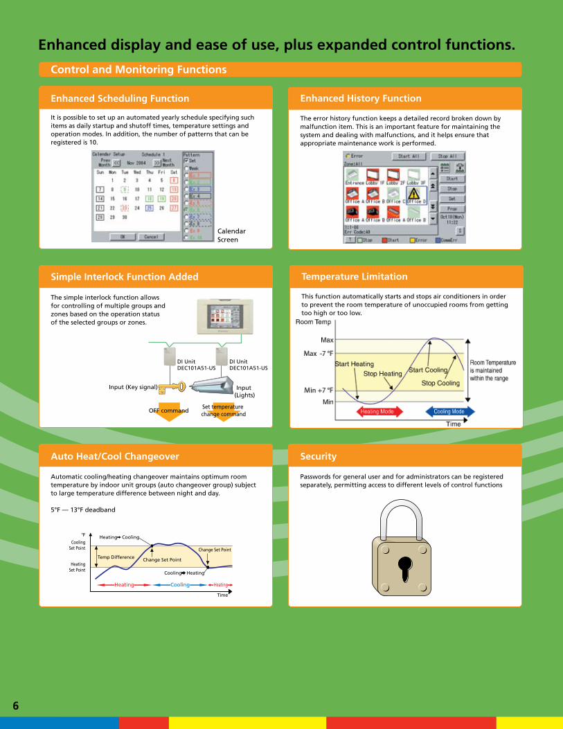
It is possible to set up an automated yearly schedule specifying such items as daily startup and shutoff times, temperature settings and operation modes. In addition, the number of patterns that can be registered is 10.
The simple interlock function allows for controlling of multiple groups and zones based on the operation status of the selected groups or zones.
Automatic cooling/heating changeover maintains optimum room temperature by indoor unit groups (auto changeover group) subject to large temperature difference between night and day.
5°F — 13°F deadband
Passwords for general user and for administrators can be registered separately, permitting access to different levels of control functions
Enhanced display and ease of use, plus expanded control functions.
Input (Lights)
Input (Key signal)
DI UnitDEC101A51-US
DI UnitDEC101A51-US
Set temperature change command
OFF command
6
Calendar Screen
Enhanced Scheduling Function
Simple Interlock Function Added
SecurityAuto Heat/Cool Changeover
The error history function keeps a detailed record broken down by malfunction item. This is an important feature for maintaining the system and dealing with malfunctions, and it helps ensure that appropriate maintenance work is performed.
Enhanced History Function
Temperature Limitation
This function automatically starts and stops air conditioners in order to prevent the room temperature of unoccupied rooms from getting too high or too low.
You have the ability to controlA/C systems in multiple buildingsfrom one location at your fingertips.
The user-friendly controller already features colors
and icons in the display for ease of understanding.
A wide variety of control methods enables
administrators to monitor and operate the system
even when they are away from the controller.
Control and management are possible via a standard Web browser (Internet Explorer 6.0SP1 or later in a Windows environment (PC)).
Main Monitoring Screen
User’s PC
HUB
Ethernet
A controller that offers freedom to administrators. It is possible to control the air-conditioning system, via the Internet, from home or any other location with a PC. Should a malfunction occur, a notification is sent by e-mail to a cell phone or PC (any e-mail address specified by the user). This gives administrators the freedom to leave the room/building where the controller is located.
Notes1. Microsoft Internet Explorer 6.0 SP1, or a later version, is the recommended Web browser for use with the system.2. The Java SE Version 6 plug-in from Sun Microsystems is required.
Item
Real-time status monitoring
Operation
Malfunction history display
User password setting
Functions Usable with a Web Browser
2
Control pump, lighting etc.
Monitoring of roomenter/exit sign
Input (Lights)
Input (Lights)
Max 8 point
Output (Indoor units)
Output
Input (Key signal)
Input (Key signal –general-purpose ADP)
Simple Interlock FunctionThe simple interlock function allows for controlling of multiple groups and zones (e.g., ON/OFF; R/C rejection; Operation mode; Set temperature; Ventilation mode; Ventilation rate setting) based on the operation status (or contact input status in the case of DI unit and DIO unit) of the selected groups or zones.
Usage example
DI UnitDEC101A51-US
DI UnitDEC101A51-US
DIO UnitDEC102A51-US
DI UnitDEC101A51-US
DI Unit DI Unit
D -NET
System
Energy is conserved by increasing/decreasing the set temperature for the indoor units when one of the lights in the same office is turned OFF. (The set temperature increases when cooling and decreases when heating.)
Turns off all indoor units and lights after somebody leaves the office or the like (and locks the doors) without turning these off. Combining the temperature limit function in commercial spaces allows for improved comfort upon the next entry into the room by maintaining a constant room temperature when the user is out. In the simple interlock function, the temperature limit function can be activated when the indoor units are turned OFF.
D -NET
Lighting interlock Key interlock
Detects when the door is locked
Detects when one of the lights is turned OFF
Set temperature change command
Set temperature change command
Set temperature change command
OFF command
OFF command
3
User-friendly icon-based centralized controller simplifiesthe VRV System.
Support for centralized control remotely using a PC with a Web browser (Optional)
Sending of e-mail alerts to a specified address if malfunctions occur (Optional)
Built-in Ethernet port for connecting to the internet or intranet
Management of facilities and ancillary equipment other than A/C units(Compatible with DIO unit and DI unit)
Simple Interlock Function
Indoor unitOutdoor unit Indoor unit Indoor unit Indoor unit
DI Unit
Indoor Unit Indoor Unit
Indoor Unit Indoor Unit
RS-232C
DIII-NETPlus Adapter
(option)Outdoor Unit
Outdoor Unit
Error reportsvia mobile phone
Central controland/or monitoring
Forced OFFcontact input
Unificationadapter for
computerizedcontrol
PCM/CIAflash
memory
Connect up to 128 Indoor UnitGroups (256 indoor units)with DIII-NET Plusadapter (option)
PI PortConnection to electrical meterwhen using power proportional distributionfunction (optional)
CSV output of powerproportional distribution
(PPD) results (optional)
Control pumplighting fixtures etc.
Digital Input/Output (DIO) Unit
Monitoring of roomenter/exit sign
Remote monitoringand control,error report
via internet, e-mail
Emergency shutoff
rical propo
puUnificationForced OFF
Outdoor UnitOutdoor Unit
Forced OFF Unification
PI PortConnection to electrwhen using power pfunction (optional)
ut
Control and Monitoring Functions
Icon Display
Displaychange
List Display
Selection of icon orlist display
Selection of zone orgroup display
ON/OFF settings for selected groups and/or zones
Complete display of the status of all indoor units
Display of zone name
Various icons that you can set yourself
Displays current date and timeDisplays system condition
(forced shutdown, etc.)
Can display detailed legend
Allows you to set the name of the individual unit
Allows easy operation of a variety of functionsincluding the setting of operation mode andtemperature.
The user can switch between the icon display, a list display and an icon detail display as desired.
Setting of operation mode according to respective purpose
Temperature setting according to respective purpose
Displays detailed air conditioner information/data
Screen related to advanced operation (seldom-used screen)
An often-used operation screen
ON/OFF of all air conditioners
Color LCDScreen
Touch ScreenOperation
IconDisplay
2 Selection by touch1 Page Up/Down
Icon Detail Display
7
Control and Monitoring Functions
°F
CoolingSet Point
HeatingSet Point
Heating
Heating
Cooling
HeatingCooling
Heating
Time
Cooling
Temp Difference Change Set Point
Change Set Point
It is possible to set up an automated yearly schedule specifying such items as daily startup and shutoff times, temperature settings and operation modes. In addition, the number of patterns that can be registered is 10.
The simple interlock function allows for controlling of multiple groups and zones based on the operation status of the selected groups or zones.
Automatic cooling/heating changeover maintains optimum room temperature by indoor unit groups (auto changeover group) subject to large temperature difference between night and day.
5°F — 13°F deadband
Passwords for general user and for administrators can be registered separately, permitting access to different levels of control functions
Enhanced display and ease of use, plus expanded control functions.
Input (Lights)
Input (Key signal)
DI UnitDEC101A51-US
DI UnitDEC101A51-US
Set temperature change command
OFF command
6
Calendar Screen
Enhanced Scheduling Function
Simple Interlock Function Added
SecurityAuto Heat/Cool Changeover
The error history function keeps a detailed record broken down by malfunction item. This is an important feature for maintaining the system and dealing with malfunctions, and it helps ensure that appropriate maintenance work is performed.
Enhanced History Function
Temperature Limitation
This function automatically starts and stops air conditioners in order to prevent the room temperature of unoccupied rooms from getting too high or too low.
You have the ability to controlA/C systems in multiple buildingsfrom one location at your fingertips.
The user-friendly controller already features colors
and icons in the display for ease of understanding.
A wide variety of control methods enables
administrators to monitor and operate the system
even when they are away from the controller.
Control and management are possible via a standard Web browser (Internet Explorer 6.0SP1 or later in a Windows environment (PC)).
Main Monitoring Screen
User’s PC
HUB
Ethernet
A controller that offers freedom to administrators. It is possible to control the air-conditioning system, via the Internet, from home or any other location with a PC. Should a malfunction occur, a notification is sent by e-mail to a cell phone or PC (any e-mail address specified by the user). This gives administrators the freedom to leave the room/building where the controller is located.
Notes1. Microsoft Internet Explorer 6.0 SP1, or a later version, is the recommended Web browser for use with the system.2. The Java SE Version 6 plug-in from Sun Microsystems is required.
Item
Real-time status monitoring
Operation
Malfunction history display
User password setting
Functions Usable with a Web Browser
2
Control pump, lighting etc.
Monitoring of roomenter/exit sign
Input (Lights)
Input (Lights)
Max 8 point
Output (Indoor units)
Output
Input (Key signal)
Input (Key signal –general-purpose ADP)
Simple Interlock FunctionThe simple interlock function allows for controlling of multiple groups and zones (e.g., ON/OFF; R/C rejection; Operation mode; Set temperature; Ventilation mode; Ventilation rate setting) based on the operation status (or contact input status in the case of DI unit and DIO unit) of the selected groups or zones.
Usage example
DI UnitDEC101A51-US
DI UnitDEC101A51-US
DIO UnitDEC102A51-US
DI UnitDEC101A51-US
DI Unit DI Unit
D -NET
System
Energy is conserved by increasing/decreasing the set temperature for the indoor units when one of the lights in the same office is turned OFF. (The set temperature increases when cooling and decreases when heating.)
Turns off all indoor units and lights after somebody leaves the office or the like (and locks the doors) without turning these off. Combining the temperature limit function in commercial spaces allows for improved comfort upon the next entry into the room by maintaining a constant room temperature when the user is out. In the simple interlock function, the temperature limit function can be activated when the indoor units are turned OFF.
D -NET
Lighting interlock Key interlock
Detects when the door is locked
Detects when one of the lights is turned OFF
Set temperature change command
Set temperature change command
Set temperature change command
OFF command
OFF command
3
User-friendly icon-based centralized controller simplifiesthe VRV System.
Support for centralized control remotely using a PC with a Web browser (Optional)
Sending of e-mail alerts to a specified address if malfunctions occur (Optional)
Built-in Ethernet port for connecting to the internet or intranet
Management of facilities and ancillary equipment other than A/C units(Compatible with DIO unit and DI unit)
Simple Interlock Function
Indoor unitOutdoor unit Indoor unit Indoor unit Indoor unit
DI Unit
Indoor Unit Indoor Unit
Indoor Unit Indoor Unit
RS-232C
DIII-NETPlus Adapter
(option)Outdoor Unit
Outdoor Unit
Error reportsvia mobile phone
Central controland/or monitoring
Forced OFFcontact input
Unificationadapter for
computerizedcontrol
PCM/CIAflash
memory
Connect up to 128 Indoor UnitGroups (256 indoor units)with DIII-NET Plusadapter (option)
PI PortConnection to electrical meterwhen using power proportional distributionfunction (optional)
CSV output of powerproportional distribution
(PPD) results (optional)
Control pumplighting fixtures etc.
Digital Input/Output (DIO) Unit
Monitoring of roomenter/exit sign
Remote monitoringand control,error report
via internet, e-mail
Emergency shutoff
rical propo
puUnificationForced OFF
Outdoor UnitOutdoor Unit
Forced OFF Unification
PI PortConnection to electrwhen using power pfunction (optional)
ut
© 2008 Daikin Industries, Limited.
Daikin®, Daikin® AC are trademarks pending or registered trademarks of Daikin Industries, Limited. All rights reserved.
– Daikin’s products are subject to continuous improvements. Daikin reserves the right to modify product design, specifications and information in this brochure without notice and without incurring any obligations.* The Power Proportional Distribution (PPD) feature supplies the user with a reasonably calculated apportionment of the total power consumption by the Daikin air-conditioning system to individual units on the system. Because input to the
PPD includes measured pulses in the refrigerant system and because the air-conditioning system includes a number of variables, including operating temperatures and pressures, piping length, heat exchange rates and others, no meter-type apportionment of individual users’ consumption can be made. However, the PPD feature provides an apportionment methodology that uses highly advanced technology as applied to the many variables in an air-conditioning system.
PCITUSE08-09C
Daikin AC (Americas), Inc. 1645 Wallace Drive, Suite 110
Carrollton, TX 75006 [email protected]
866-4DAIKIN (972) 245-1510
Dealer Information
Communication Capabilities via a Touch Screen or a Web Browser Further Expand Air-Conditioning Control Possibilities.
More Freedom to Administrators
Malfunction Reportsto a Mobile Phone, AnywhereMalfunction reportsdelivered by e-mail(Optional)
Connectable up to128 Indoor Unit Groups(256 indoor units)
Control Daikin SystemsRemotelyCentralized monitoring controlsystem based on a Webbrowser (Optional)
The air conditioners manufactured by Daikin Industries have received ISO 9000 series certification for quality assurance.
Certificate Numbers: (ISO9001) JMI-0107 (ISO9002) JQA-1452 JQA-1452
All Daikin Industries locations and subsidiaries in Japan have received environmental management system standard ISO 14001 certification.
Daikin Industries, Ltd.Domestic GroupCertificate Number: EC99J2044
ISO 14001 is the standard defined by the International Organization for Standardization (ISO) relating to environmental management systems. Our group has been acknowledged by an internationally accredited compliance organization as having an appropriate program of environmental protection procedures and activities to meet the requirements of ISO 14001.
About ISO 14001
SpecificationsINTELLIGENT TOUCH CONTROLLER DIII-NET PLUS ADAPTER
Reference DCS601C71 DCS601A72
Power Supply Externally supplied AC24V, 50/60Hz AC24V, 60Hz ± 10%
Power consumption 10 W maximum 5 W maximum
Operating condition Surrounding temperature 32° F to 104° F 14° F to 104° F
Humidity Less than 85% RH (non condensing) 20% to 90% RH (non condensing)
Dimensions HxWxD inches 5-25/32 x 9-1/16 x 4-7/32 7-15/32 x 6-3/16 x 1-21/32
LCD panel size / # of dots / # of colors 5.7 inches / QVGA 320x240 / 4,096 colors —Maximum number of indoor units 64 groups (maximum 128 indoor units) Use in conjunction with DCS601C71 to connect
an additional 64 groups (maximum 128 indoor units)
Maximum number of outdoor units 10 10
Input Touch panel 10 bit encoded analog input —Communication functions Dlll-NET x 1 Air conditioning equipment communication line Air conditioning equipment communication line
10BASE-T Web option —
PCMCIA slot Flash memory card used for PDD —
RS232C — Interface to i-Touch ControllerInput terminals Digital input Di x 1 Forced shutdown —
F1-F2 x 1 — DIII-NET connection to VRV outdoor units
Pulse input Pi x 3 Power measuring pulse 1 pulse at 1 or 10 kWh and 40-400 msec
Overseas certification Interference (EMC) FCC Part 15 Subpart B Class A FCC Part 15 Subpart B Class AProject data and engineering Configuration and engineering for each project
are necessary. For further details, please consult with Daikin distributors and dealers.
Configuration and engineering for each project are necessary. For further details, please consult with Daikin distributors and dealers.
AccessoriesDESCRIPTION REFERENCE COMMENTS COMMENTS
Software DCS002A71 Power Proportional Distribution (PPD)* —
DCS004A71 E-mail / Web software —
Installation box KJB411A For wall mounted installation —
Interface adapters KRP928B2S For connection to Split units —
Digital input DEC101A51-US Input contacts: 8 inputs + 8 alarm inputs Input contacts: 8 inputs + 8 alarm inputsDigital input/output DEC102A51-US Input contacts: 4 inputs + 4 alarm inputs
Output contacts: 4 outputsInput contacts: 4 inputs + 4 alarm inputsOutput contacts: 4 outputs
Connector cable RS232C — 32-foot connector cable (included)
kWh meterITEM REQUIREMENT SPECIFICATION
kWh meter Pulse transmitter – 1 Pulse to 1kW or 10 kW pulse width must be between 40 - 400 msec– Output relay must be electronic type only. – No voltage output