COMMONWEALTH OF KENTUCKY CHARLES PRYOR, JR. …
36
CHARLES PRYOR, JR. ;OMMISSIONER OF HIGHWAYS COMMONWEALTH OF KENTUCKY DEPARTMENT OF HIGHWAYS FRANKFORT, KENTUCKY 40601 September 5, 1972 ADDRESS REPLY TO: DEPARTMENT OF HIGHWAYS DIVISION OF RESEARCH 533 SOUTH LIMESTONE STREET LEXINGTON, KENTUCKY 40508 Tt:':LEPHONE 606·254-4475 H.2.24 MEMORANDUM TO: W. B. Drake SUBJECT: Assistant State Highway Engineer Research and Development Research Report 338; "Skid·Test Trailer: Description, Evaluation and Adaptation;" KYHPR·64-24; HPR·1(8), Part II We have prepared the enclosed report for limited distribution. It is for record and information to those most intimately concerned with skid testing and testing equipment. It requires no implementation and involves no recommendations. The substance herein has been separated from a companion report (No 331, "Skid Resistance of Pavements," July 1972). It is also complementary to a current report entitled "Accidents on Interstate and Parkway Roads and Their Relation to Pavement Friction'' (No 339, September 1972). JHH:dw Attachment cc: B. R. Flener (attn. B. Maffet) Director of Research
Transcript of COMMONWEALTH OF KENTUCKY CHARLES PRYOR, JR. …

CHARLES PRYOR, JR.
;OMMISSIONER OF HIGHWAYS
COMMONWEALTH OF KENTUCKY
DEPARTMENT OF HIGHWAYS
FRANKFORT, KENTUCKY 40601
September 5, 1972
ADDRESS REPLY TO: DEPARTMENT OF HIGHWAYS
DIVISION OF RESEARCH
533 SOUTH LIMESTONE STREET
LEXINGTON, KENTUCKY 40508
Tt:':LEPHONE 606·254-4475
H.2.24
MEMORANDUM TO: W. B. Drake
SUBJECT:
Assistant State Highway Engineer
Research and Development
Research Report 338; "Skid·Test Trailer: Description, Evaluation and
Adaptation;" KYHPR·64-24; HPR·1(8), Part II
We have prepared the enclosed report for limited distribution. It is for record and information
to those most intimately concerned with skid testing and testing equipment. It requires no implementation
and involves no recommendations. The substance herein has been separated from a companion report
(No 331, "Skid Resistance of Pavements," July 1972). It is also complementary to a current report
entitled "Accidents on Interstate and Parkway Roads and Their Relation to Pavement Friction'' (No
339, September 1972).
JHH:dw
Attachment
cc: B. R. Flener (attn. B. Maffet)
Director of Research


TECHNICAL REPORT STANDARD TITLE PAGE
1. Report No. 2. Government Accession N'o. 3. Recipient's Catalog No.
4. Title and Subtitle 5. Report Date
Skid-Test Trailer: Description, Evaluation, and Adaptation September 1972 6. Performing Orgoni zotion Code
7. Author! s) 8. Performing Orgoni zotion Report No.
R. L. Rlzenbergs, J. L. Burchett, and C. T. Napier 338
9. Performing Organization Nome and Address 10. Work Unit No.
Division of Research Kentucky Department of Highways 11. Contract or Grant No.
533 South Limestone KYHPR- 64-24
Lexington, Kentucky 40508 13. Type of Report and Period Covered
12. Sponsoring Agency Nome and Address
.t;';zod. Interim
14. Sponsoring Agency Code
15. Supplementary Nates
Prepared in cooperation with the US Department of Transportation, Federal Highway Administration
Study Title: Pavement Slipperiness Studies
16. Abstract
A twoMwheeled skid-test trailer and towing vehicle were acquired in 1969. The
trailer was designed primarily for measurement of steady-state friction at and above
normal traffic speeds. Measurement of instantaneous wheel loads also permitted
determination of peak or incipient friction. Factors and variables associated with the
testing device and calibration and test procedures were investigated and standardized,
and the trailer was adopted for routine testing. Comparative tests with the trailers of
General Motors, Ohio, and West Virginia were conducted, and the data were correlated.
The interim standard method of test using an automobile was correlated with the trailer
to permit conversion of data accumulated in preceding years.
17. Key Words 18. Distribution Statement
Skid Resistance Incipient Friction Pavement Friction Skid-Test Trailer Trailer Correlations
19. Security Clossif. (a/this report) 20. Security Classif. (of this page) 21. No. of Pages 22. Price
Unclassified Unclassified '---Form DOT F 1700.7 ts-s91


Research Report 338
SKID-TEST TRAILER: DESCRIPTION, EVALUATION AND ADAPTATION
INTERIM REPORT KYHPR-64-24; HPR-1(8), Part II
by
Rolands L. Rizenbergs Research Engineer Chief
James L. Burchett Research Engineer Senior
and
Cass T. Napier Research Engineer Associate
Division of Research DEPARTMENT OF HIGHWAYS
Commonwealth of Kentucky
in cooperation with the U.S. Department of Transportation
Federal Highway Administration
The contents of this report reflect the views of
~he authors who are responsible for the facts and
the accuracy of the data presented herein. The
contents do not necessarilY reflect the official
views or poncles of the Department of Highways
or the Federal Highway Administration. This
rt;~port does not constitute a standard,
specification, or regulation.
September 1972


INTRODUCTION
The Division of Research acquired a
commercially-built two-wheeled skid-test trailer and a towing vehicle in 1969. The unit was designed to measure steady-state friction at and above normal traffic speeds and included research fea lures. Analog recordings of instantaneous wheel loads and horizontal forces has enabled measurement of peak or incipient friction. Testing became easier, cos( less, and could be done more safely. Comparative tests were conducted among several trailers, and the data were correlated. The interim standard method using an automobile in skid testing, employed previously, was correlated with the trailer on several pavement types. Analog record reduction
instrumentation was acquired to facilitate processing
oscillograph strip-chart recordings. The digitized data, placed directly on punch cards, permitted computer
calculations.
METHOD OF TEST
Present trends in the United States are toward the use of a locked wheel method of test-- more specifically,
a towed trailer as standardized by ASTM E 274-70 (1). The measurement represents steady-state friction
between a standard test tire (ASTM E 249-66) (2) and a wetted pavement. The locked wheel(s) is (are) dragged·
at a constant speed and load over the pavement, and the results are expressed as Skid Numbers, SN.
SIQD TRAILER UNIT
Truck and Trailer The skid tester acquired by the Division of
Research was developed by Gep.eral Motors Proving Ground and manufactured, under a licensing agreement
with the GM Corporation, by K. J. Law Engineers, Inc.,
Detroit, Michigan. The Surface Dynamic Pavemeut Friction Tester, Model 965A, complies fully with ASTM E 274-70 and has several features designed for greater
research flexibility which are not covered in the ASTM standards. Complete purchase specifications are
presented in APPENDIX A. The unit, Figure I, consisted of a 3/4-ton pickup
truck and a towed two-wheeled trailer. The truck was
a Chevrolet, Series 20, Custom Sport Pickup with au~omatic transmission, power steering, power brakes
and air conditioning. It has a 396 cubic inch, 310 horsepower engine. The truck has a Power-Lock 3.54
to I differential and heavy duty suspension. A Bendix-Westinghouse Tu Flo 400 air compressor,
mounted on the engine, provided compressed air which
was stored in two tanks located underneath the truck bed. The air was preconditioned in an assembly consisting of a filter bottle, desiccant bottle, regulator, and lubricator. This assembly was mounted at the rear of an aluminum water tank. The water tank, mounted
in the truck bed behind the cab, was internally baffled and held 230 gallons. Two pumps beneath the truck bed moved the water from the tank to the trailer. Each pump was driven by a gear belt from the driveshaft and controlled by an electric clutch. The towing hitch assembly at the rear of the truck could be vertically adjusted to level the trailer tongue to compensate for varjed truck and trailer loads. The trailer, Figure 2, had
a perimeter-type frame constructed of two-inch by four-inch rectangular, box sectional steel tubing, and the trailer tongue was a four-inch box section with a
two-inch ball-joint hitch. The trailer suspension was of a trailing arm design
with an upper and lower control arm on each side, coil
~prings, air-adjustable shock absorbers, and an anti-sway bar. Each wheel was coupled by a disc brake assembly to a calibrated force transducer which measured the tractive as well as the vertical forces on the wheel. A nozzle dispensed water to the pavement ahead of the tire during tests. A fifth wheel, mounted near the rear
of the trailer, measured vehicle speed. Tachometer generators, connected to each of the trailer wheels, measured the rotational velocity of the wheels. An
air-to-hydraulic converter, hydraulic controls, and other components were mounted on panels fitted to the riser
section of the frame. Fifty-pound weights could be added or removed from the trailer to vary its weight
from 1600 to 2600 pounds. Electrical power was derived from the truck's
battery and a 62-ampere Delcotron alternator. A
DC-to-AC converter and DC power supplies were mounted behind the cab seats. Measurement instrumentation, including an oscillograph recorder, and
operating controls were located in a console between
the driver and passenger seats as shown in Figure 3. A speed error meter was mounted on top of the dashboard in front of the driyer.
Operational Systems Operationally, the tester consisted of four
interrelated systems: I) mode controls, 2) pneumatic and hydraulic, 3) pavement wetting, and 4) transducers and instrumentation for measuring, conditioning, and
recording.

Figure 1. Surface Dynamics Pavement Friction Tester.
Mode Controls: Pnshbuttons were provided on the control console, Figure 3, to separately arm the water and brake application for each wheel, to lower and raise the fifth wheel, and to cycle through the test. Three cycling modes were available: !) manual, 2) semi-automatic, and 3) automatic. In the manual mode, the chart, water and brake switches were depressed by the operator sequentially to initiate and to terminate testing. In the semi-automatic mode, the Auto Operate switch was depressed and held in position to actuate chart drive, water pumps and discharge solenoids, and, after a time delay, brakes. Releasing of the switch discontinuod the water application, braking and, after a time delay, the chart drive. The automatic mode was actuated by pressing the Auto Drop Out switch and by arming the desired wheel to be braked with or without water application. Thereafter, pressing of the Auto Operate switch initiated the same sequence in testing as in the semi-automatic mode.
The remaining controls were Lock Up Rate Selector and Vehicle Speed Selector. The Lock Up Rate Selector consisted of an air regulator valve, an air flow directional valve, and an electric switch. These allowed three lockup modes: I) unrestricted air flow to the hydraulic system with braking delayed, allowing pressure to increase and thus obtaining an extremely fast lockup when released, 2) unrestricted air flow directly to the braking system with lockup resulting approximately
2
one-half second later, and 3) restricted air flow to the braking system to delay lockup up to ten seconds. The Vehicle Speed Selector was used to set the speed at which tests were to be made. This value registered as the zero setting On the speed error meter.
Pneumatic and Hydraulic: Air pressure, I 00 psi, developed by the compressor upon command operated the water valves, raised and lowered the water nozzles and the fifth wheel, and supplied power for the hydraulic system -· by means of a pump converter. Air from the system was also used to power an impact wrench, to maintain proper tire pressure, and to supply air for the air bearing platform used in supporting wheels during calibrations of the force transducers.
The main function of the hydraulic system was to power the test wheel brakes. Pressure, up to 2500 psi, was supplied by an air-to-hydraulic converter; sufficient fluid reserve was maintained in a reservoir. Either one or both of the wheels may be braked. When the system was activated, hydraulic pressure was applied to the disc brake{s). Upon deactivation, the pressure was released to the reservoir.
Additiomil components of the hydraulic system were two jacks which operated simultaneously to raise or lower the trailer. After the jacks were armed {both wheels are automatically braked), a manual valve, located on the tongue, commanded the jacks.
Figure 2. Trailer with Hood Raised.
Figure 3. Control Console .
3

Pavement Wetting: To simulate wet-road conditions for testing, water was applied to the pavement ahead of the wheel(s) being braked. Two pumps, one for each wheel, drove the water from the tank to the trailer. Each pump was driven by a gear belt off the driveshaft; and, thereby, the volume of water moved was directly proportional to the vehicle speed, An electric clutch was located between each power take-off a11d pump, To properly wet the pavement in front of the test tire(s), water flowed through specially designed nozzles, which, by means of internal dividers, distributed the water uniformly, During tests, the nozzles were lowered by pneumatic pistons to within two inches of the surface, However, by raising or lowering the mountings of the pistons, this distance could be adjusted between zero and four inches, The water strikes the pavement about 13 inches from the vertical center line of the tire, The width of the nozzle at the discharge end was 5 1/2 inches and this provided about nine inches of wetted width at the tire, Two air-controlled solenoid valves, located near the nozzles, keep water from draining out of the water lines between tests.
The pavement wetting system could be armed for left-wheel tests, right-wheel tests, or both, When the system was activated, the electric clutch(s) engaged, the valve(s) opened, and the nozzle(s) lowered. Water then flowed until the system was deactivated at the end of the test. Approximately 100 one-wheel tests could be conducted at 40 mph with one tank of water.
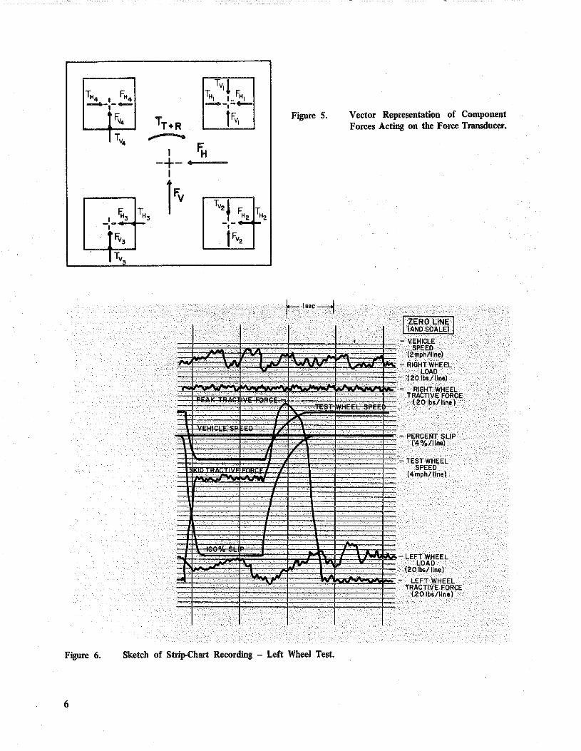
Transducers and Instrumentation: The force transducers, Figure 4, were machined from a block of stainless steel. The four identical cross beams were symmetrical about the center axis of the transducer. Strain gages were precisely mounted on the outer faces of each beam, equal distance (about one-quarter the length) from each end. The wheel load (vertical) force, tractive (horizontal) force and torque acted on the transducer. The torque resulted both from the tractive force with a moment arm equal to the radius of the wheel and from the wheel load with a moment arm equal to the combination of the tire patch relocation and the distance from the transducer to the tire. Due to the symmetry of the cross beams, each beam assumed one-fourth of the forces and torque. As depicted in Figure 5, the tractive forces, FH, acted in the same direction as do the wheel load forces, Fv. The horizontal forces, T H (due to torque), acted in opposite directions, as did the vertical forces, Tv· Thus, by proper arrangement of the strain gage output into a wheatstone bridge, the horizontal or vertical forces -due to traction or wheel load -- were additive whereas the accompanying horizontal or vertical forces -- due to torque -- canceled.
4
A generator-tachometer was connected to each of the trailer wheels. Each tachometer generated a signal proportional to the rotational speed of the wheel. Either of the signals can be selected to be recorded, but, normally during one-wheel tests, the signal from the wheel being braked was selected. This signal was also divided by the signal from the tachometer of the other wheel and the resulting signal -- representing the percent slip of the braked wheel -- was recorded.
Transducers mounted on the fifth wheel provided two signals. A pulse signal was produced by a pulse generator connected to one end of the axle. Each pulse denoted one foot of travel of the trailer. The other signal was produced by the tachometer-generator connected to the other end of the axle. This signal was scaled and recorded as "Vehicle Test Speed." It was also compared to the Vehicle Speed Selector setting and any error was displayed by the speed error meter.
The force measuring transducers were powered and their outputs amplified, conditioned and scaled by instrumentation components in the truck console. The console also contained instrumentation for conditioning the test-wheel speed, trailer speed, and distance transducer ou(puts and for computation of percent slip of one wheel. An additional strain gage balancer and amplifier were provided for a tension load cell used in calibrating the force transducers in shop. A digital voltmeter in the console assisted in monitoring each
. transducer while performing adjustments, scaling and calibration. A Brush, Model 2300, light-beam oscillograph provided eight channels for signal recording. A sketch of the recording of a left-wheel test is presented in Figure 6. The chart paper traveled from left to right, thus events occurred from right to left.
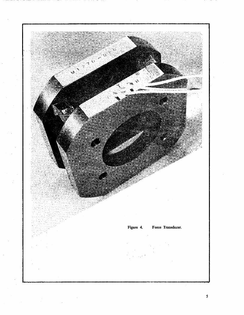
Figure 4. Force Transducer.
5
TH4 I F"• Tv11
TH, I_FH, ..-.-.-....,_ _..,_,_...,_
Fv. TT+R fFv, Figure 5.
Tv• r ... I FH
-+-I l Fv
F.; TH Tv2 ~ TH F"• I 3 3 -,-...,:;.. -· -~-
f\,3 f Fv•
Tv,
r lsec---,..j
.
~
Figure 6. Sketch of Strip-Chart Recording ·- Left Wheel Test.
6
.
Vector Representation of Compo!lent Forces Acting on the Force Transducer.
I ' -
ZERO LINE (AND SCALE)
VEHICl-E SPEED
(2mph/line) RIGHT WHEEL
LOAD (20 Jbs/Jine)
~
RIGHT WHEEL TRACTIVE FORCE
( 20 lbs/ line)
-
-
-
PERCENT SLIP (4%/Jine)
TEST WHEEL SPEED
(4mph/line)
LEFT WHEEL LOAD
20ibs/llne) (
LEFT WHEEL TRACTIVE FORCE
( 20 lbs/Jine)

PROCEDURES
Calibration -- Frictional Force and Vertical Load The force transducers were calibrated when the
trailer was received and as needed on several occasions each year thereafter. The calibration consisted of
applying a known force to the transducers, determining
the· voltage output per unit force applied and adjusting
the outputs to the desired "pounds-per-volt." With the
system properly scaled, a calibration signal was applied
to each transducer and the corresponding force values
were noted. In field testing, the system was adjusted
to these values by applying the calibration signals. Figure 7 depicts the setup for calibration of the
frictional force. The trailer wheel was placed on an air
bearing platform -- a spacer was placed under the other
wheel to level the trailer -- and the trailer was braked. A preload was applied by means of a hydraulic cylinder
to the wheel through a calibrated tension load cell, and
the voltage outputs were nulled to zero. Increasing force
was then smoothly applied and the voltage outputs of
the tension load cell and of the force transducer were
TO --fi'i"'!--.._, TRUCK ELECTRICAL POWER
TO FORCE MONITOA
HORIZ, LEVELING AREA (LONGITUDINAL)
recorded on an X-Y plotter. The resulting plot was
analyzed to check for linearity of the system and to
determine the point at which the voltage output of the
force transducer equaled the calibration signal voltage.
The voltage output of the tension load cell - converted
to force -- was the . horizontal force calibration value.
The procedure was repeated for the other wheel. The vertical force calibration procedure was based
on the fact that the difference between· the vertical
forces acting on the transducers, as the trailer wheels
were raised above ground, equaled the wheel loads. The
wheel loads were previously determined by placing each
wheel on separate weighing scales. The trailer, resting
on the ground, was leveled and the output of each
transducer was zeroed. The trailer was then raised above
ground and the output of each transducer was scaled
to the appropriate wheel load. After the trailer was
lowered to the ground, leveled, and the transducer
outputs rechecked for zero readout, the calibration
signal was applied and the vertical force calibration
values were read from the digital voltmeter.
'·~TO ANCHOR POINT
Setup for Traetive Force Cahbration of Transducer.
7

Ca/i"f>ration -- Speed The trailer speed was calibrated when needed. The
need for a recalibration was determined by speed checks performed each <:\ay on a measured mile while traveling to test sites. Calibration consisted of traversing a two-mile section at <;O!lstant speed (near 40 mph) while measuring the elapsed time. The vehicle was then operated at that speed while adjustments for th~
calculated speed were made. Proper adjusiment was verified by traversing the section twiCe. The section was then traversed at ~0, 60, a!ld 70 mph and the spee\1 variations were recorded with the aide of the oscillograph .. The resulting recordings were checked to insure proper speed indications.
Skid Test All measurements were conducted with the ASTM
E-249 specified Pavement Test Tires. New tires were preconditioned by running them at least five hours. The tires were then balanced. Prior to testing, the tires were inflated to 24 psi cold, checked for wear, and then warmed by traveling at least five miles at normal traffic speeds. The tire pressure was checked during the day to insure that it did not exceed 28 psi.
The instruments were turned on at least ten minutes before testing. The trailer unit was positioned on a level area on the shoulder or a convenient spot near the test site. The bridge circuits were nulled and calibration signals for each transducer output were adjusted for proper readout. At the first test site for the day, the galvanometers were scaled on the chart. The calibration signals were recorded at the beginning of each test section and at least once every thirty tests.
Normally, tests were conducted at 40 mph and in the left wheel path. If a skid-resistance speed gradient was desired, tests were conducted at 20, 40, and 60 mph. Occasionally, the right or l;>oth whee! paths were measured. At least five tests at the desired speed were made per test section -- or no less than one test per mile if the section was longer than five miles. Unless selected as a separate test section, tests were not made on sharp curves or steep grades. Traffic lanes were considered separately from passing lanes. The field report noted the test number, lane and wheel path tested, and speed. The start of the test section, as well as the location of each test, was noted using the truck odometer. General information recorded on each field report included pavement type, route number, county, project number, locaUon, date, time, temperature, and weather. The various field 'and lab reports used are exhibited in APPENDIX B.
8
Skid Resistance Determination Tractive force(s), wheelload(s) and other test data
were derived from the recorded signals as shown in a sketch of the recording for a left wheel test in Figure 6. Elapsed time is shown on the chart by vertical lines.
The tractive force, F, was determined by averaging the measured force over a one-second interval beginning 0.5 seconds after wheel lockup. The average dynamic or effective wheel load, W, was determined for the same interval of time. The Skid Number, SN, was then calculated as follows:
SN = (F/W) x 100
An alternate method for determining the vertical load on the te·st wheel, based on the kinematic layout of the trailer, involved the load-transfer formula
W = Wo - (H/L) F 2
where w = dynamic vertical load on the test wheel, pounds,
Wo = static vertical load on the test wheel, pounds,
H = hitch height, inches, L = trailer wheelbase length, inches, F = tractive force, pounds.
This equation accounts for the wheel-load reduction due to unloading produced by the tractive force, but the true dynamic load during the measurement interval cannot be obtained. The Skid Number was calculated using Equation 1.
The peak or incipient tractive force, I, was determined directly from the chart as the largest force occurring prior to wheel lockup. The dynamic vertical load at this point was determined, and Peak Slip Number (PSN) was obtained from the equation
PSN = (1/W) x 100. 3
The percent slip of the test wheel at the instant of peak tractive force was noted.
Skid Numbers and Peak Slip Numbers were presented without qualification when obtained from left wheel tests at 40 mph on wet pavement. Tests at other speeds were noted with a gpeed subscript, such as SN60 for skid numbers at 60 mph. Results of right wheel, both wheel, and dry pavement tests, or tests with smooth tires and with tires other than standard test tires, were so identified.

Analog Record Reduction For the first two years of testing with the trailer,
Skid Numbers were determined by manual methods of chart analysis and calculation. The manual efforts were tedious and time consuming and subject to chart reading and calculation errors. Therefore, a digital data reduction system, a Gerber Model GDDRS-3B, as shown in Figure 8, was acquired in November 1970. The device was a general-purpose data reading system capable of reading data points and converting them to digital information, and translating this information into a variety of outputs. It consisted of four basic units: a reading head, a scanner, a keyboard and a power supply The scanner was designed for rapid viewing of strip charts, films, etc. on a backlighted glass surface by feeding the chart from motor driven roll holders attached to each side of the viewing surface. A reading head was mounted on the scanner and allowed adjustment for both X and Y axis hairlines by moving both curkd knobs in front of the scanner casting. The
Figure 8. Digital Data Reduction System .
position of the hairline controlled the angular position of a shaft encoder which provided an exact position signal to the digital system. The reading head was self~contained and inclUded all circuits, controls and digital displays. The output was punched onto computer cards through direct coupling with a card punch unit. A manually operated keyboard was used for inserting other digital information into the key punch unit. The punched cards were processed through an IBM 360-65 computer with an appropriate computer program to determine individual as well as average values for SN, PSN, test speed and pertinent statistical parameters. The resultant computer print-out of data provided a convenient means by which to check for invalid data and errors. Filing and retrieval of data were also improved.
Utilization of the digital data reduction system and computer processing halved chart analysis and calculation time.
9

TEST V ARIA!ILES
Tire Pressure A series of two-wheel measurements were
performed on a concrete pavement at 40 mph to note the effects on test results of changes in tire pressure. Tests were made at inflation pressures from 22 psi to 32 psi in increments of 2 psi. The data, as presented in Figure 9, indicated a maximum deviation of two percent (1 SN and 1 1/2 PSN) over the normal operating range of 24 to 28 psi. The ASTM E 274-70 specifies 24 ± 0.5 psi at ambient temperature B(co1d). Pavements having different textural characteristics may exhibit somewhat larger, or smaller, variations in friction, but control of tire inflation pressure within the cited limits apparently does not signtficantly affect results.
Static Wheel Load ASTM E 274-70 specifies a static load of 885 to
1,085 pounds for each wheel. The lower wheel load, of course, minimizes power demand on towing and reduces wear on brakes .• suspension, etc. Therefore, a series of two-wheel tests was conducted on a concrete pavement to select a standard test load. The results are shown in Figure I 0. A 200-pound decrease in load resulted in approximately a five percent change in skid resistance (2 SN and 4 PSN). As a compromise, a 1 ,000-pound load was chosen. Maximum difference between other trailers due to unlike wheel loads, therefore, would be approximately I SN.
Dynamic Wheel Load Pavement roughness, transient effects due to wheel
lockup and load transfer to the trailer hitch caused load changes about the static wheel load. The load transfer to the hitch could be calculated (H/L)F but the reliability is in doubt since the hitch height, H, does not remain fixed during the test. If the instantaneous, dynamic wheel load is measured throughout the test interval, an effective wheel load can be obtained which accounts for all of the aforesaid variables. To note the differences in test results between the direct measurement of wheel load and the calculated wheel load involving the load-transfer formula, Equation 2, the SN and PSN of 24 test sections were determined by both methods. The mean values are presented in ·Figure II. The Skid Numbers were sufficiently close to suggest that measurement of wheel load may not be essential but, never-the-less, desirable tf greater precision is to be realized. The Peak Slip Numbers, however, exhibited a mean difference of about four percent, indicating that wheel~load measurement was necessary to accurately determine incipient friction of pavements.
10
a:: ~ 40 f---'-f-~4-~-+-'-'-'-'-+-".;:.c...'---j ::;; ..
·:::> z g 35 f---'-f---,C+---+---+-"-'---1 s::· (/)
Figure 9.
~ 25 ~ 35 ~·
INFLATION PRESSURE , PSI
Skid and Peak Slip Resistance of a Concrete Surface as a Function of Tire Inflation Pressure.
I5 so .----"-,........----.----.:-'--"~,;:,
~ z ri 70 h------+-'---'--+-'--~-1-----l
·ci .. ~ ..... . i5 q() t:...;....,...___J._:__;_~----+--.-J a..
~50 . ..--~------~----~~~ lJJ Ill :E•. :::> Z40·h~~~~~--'---I----
O s.::: IJ) 30 L;c"'"'-"___.l---L-c.c....c..L.. ___
·.• 800 900 1000 1100 1200
Figure 10.
WHEEL. LOAD , LBS.
Skid and Peak Slip Resistance of a Concrete Surface as a Function of Wheel Load.

Figure 11. Mean Skid and Peak Slip Resistance on Twenty-Four Pavements, Calculated by
ASTM Weight Transfer Formula and From Measured Dynamic Wheel Load as
a Function of Speed.
CORRELATION WITH OTHER TRAILER UNITS
General Motors Comparative tests were conducted between the
Kentucky and the GM (Model II) trailers at the General
Motors Proving Ground in August 1969. Due to a
malfunction of the GM trailer, only right-wheel tests
were made; these involved both external and
self-watering pavement wetting. The test results are
presented in Figure 12. The self-watering test results
were almost identical and are represented by a single
curve. External watering obviously did not provide
uniform water thickness.
Ohio and West Virginia At the invitation of the West Virginia Department
of Highways, the states of Ohio, West Virginia, and
Kentucky conducted comparative tests in June 1971 on
20 experimental' paving sections constructed on US 35
in Putnam County, West Virginia. The results were
reported by West Virginia (3). Each trailer performed two-wheel tests at 25, 40,
and 65 mph. Tests were not performed under closely
controlled conditions. The 65-mph tests were conducted
in rainy weather and portions of the tests by West
Virginia were made the previous day during sunny
weather and, therefore, at higher pavement
temperatures. The trailers were calibrated by individual
states in their facilities and using their own calibration
procedures. Since the comparative tests, approximately ten
percent error was discovered in the Ohio's left wheel
measurements and, therefore, the Kentucky and Ohio
testers were compared by using the right wheel measurements as shown in Figure 13. The complete test
data for the two trailers are presented in Table I. The
trailers correlated well at all speeds, but a 1: I relationship was realized for only a limited range of
values.
II

The data supplied by West Virginia as presented in Table II, combined the left and right wheel measurements and expressed them as projected Skid Numbers at 55 mph and 70 mph although tests were made at the speeds Cited earlier. Correlations between the Kentucky and West Virginia measurements are presented in Figure 14. Good correlations were obtained when the data for each speed were considered separately. The only point at which the data compared I: 1 was at 70 mph and SN of 60.
No attempt was made to reconcile the differences found between trailers. The Ohio trailer unit, also fabricated by K. J. Law Engineers, Inc., was in most respects identical to the Kentucky unit, except that it utilized torque transducers in measuring tractive forces and did not incorporate transducers for measuring wheel loads. The West Virginia unit, fabricated by Soiltest, Inc., was of entirely different design.
CORRELATION BETWEEN AUTOMOBILE AND TRAILER
Prior to the acquisition of the skid trailer, measurements were conducted with an automobile (4, 5, 6, 7). The test consisted of skidding an automobile with its wheels fully locked on a wetted pavement surface from a velocity above 35 mph to 0 mph. From a recording of velocity and time, or distance, the coefficient of friction between 30 mph and 20 mph was calculated. The automobile method of test represented non-steady-state skidding; whereas, the trailer test involves steady-state sliding. The results of the two measurements may not necessarily be identical even if the test speeds involved were the same. Furthermore, skid resistance of pavements are greatly speed dependent, and each type of surface exhibits its own speed gradient. Trailer tests, as stated earlier, are normally conducted at 40 mph, but speeds of 20 mph, 60 mph and even 70 mph may also be employed. Correlation of the two methods of test, therefore, must be made to convert previous data to equivalent trailer values.
Test sections, comprised of several pavement types, were selected and represented low-to-high friction. The trailer and automobile measurements on each section were performed almost simultaneously on warm days and utilized test tires from the same batch of manufacture and with approximately the same wear.
A separate correlation was warranted for each pavement type. The results of the regression analysis are presented in Table III. The test data and plots of the regression equations are shown in Figure 15. The
12
GM KY
li ~ SELF WATERING
EXTERNAL WATERING
39a:C· --"--:2,':0--,---3:-'0,---..J4L0~-5LQ_~60
SPEED, MPH
Figure 12. Correlation of Trailer Units -- Kentucky and G. M. Proving Ground (Model II).

B 0
7 0
.. 6 0
· ..
0 5: 5 8 0::
:il4 :;;
0
0
::::> .. ""· 93
"' en 0
2 0
10
I.
0 0
..
. .
I
. I
.
10
0
/ TRAILER SPEED
~ /
0 25 MPH $ 40MPH 4 65 MPH
/ . v "'
i1' fC EQUATION Es R
. SN (OHIO)~ 0,92 SN (KY) + 2.5 2.1 0,989
• .
!
20 30 40 50 60 70 80 SKID NUMBER (KENTUCKY)
Figure 13. Correlation of Trailer Units -· Kentucky and Ohio.
8 0
. . L 0
.
TRAILER SPEED rY 0 25 MPH . 0 40 MPH
. ·. A 70-MPH / 0
~ •• ~ .
0 .· . .
.
:J ~r 0
1 ..•
..
•• . .
I •..•. .. · f(tf• I I ·/ 0
·.· .. ·.
• .
• •••
1{ • I
••• li ·. .· .. 0 L
SPEED EQUATION Es R
7
. 2{i MPH SN (W.VA) ~ 0.54 SN (KY) + 10.0 12 0.967
Q . . 40 MPH SN 1W.VA) ~ 0.92 SN {KY) T 8.1 II 0.992 -. * 55 MPH SN (W.VA) = 0.96 SN (K.Yl t 7.5 14 0.988
·.•·· 70.MPH SN (W.VAJ = 0.99 SN (KYl + 7.0 16 0.984
0 * ·NOT PLOTTED
0 IO 80 20 30 40 50 60 70
SKID NUMBER (KENTUCKY)
Figure 14. Correlation of Trailer Units -- Kentucky and West Virginia.
13

TABLE I
COMPARATIVE TESTS ~ KENTUCKY AND OHIO
SKID NUMBER
SECTION 25 MPH 40 MPH 65 MPH
NUMBER* l<Y OHIO KY OHIO l<Y OHIO
LEFT RIGHT LEFT RIGHT LEFT RIGHT LEFT RIGHT LEFT RIGHT LEFT RIGHT
lN 77 79 70 77 67 69 59 66 51 53 42 48 2N 65 69 63 68 56 60 52 56 34 38 34 37 3N 64 69 57 63 48 48 43 48 31 31 30 33 4N 75 80 71 80 65 68 60 68 53 52 43 50 5N 63 65 59 64 53 54 45 51 36 37 31 35 6N 53 49 48 50 40 40 31 33 24 24 27 7N 58 60 56 59 45 46 41 46 32 32 23 31 8N 53 55 48 54 40 42 38 42 24 26 25 29 9N 51 54 46 43 40 44 35 42 26 30 25 28
lON 54 57 50 55 47 46 39 45 30 28 33 lS 54 53 48 50 38 38 38 39 27 28 23 25 2S 47 47 41 45 34 36 33 35 24 26 22 25 36 52 52 46 46 37 38 35 36 24 25 23 26 4S 50 49 45 45 34 32 34 34 24 22 20 22 ss Sl 54 49 52 37 37 37 39 27 26 23 26 6S 61 68 57 " 48 49 45 49 35 35 28 33 76 61 65 54 62 50 49 45 50 40 38 36 35 as 65 67 57 64 54 50 48 52 37 34 37 96 61 68 62 63 52 49 4.7 49 34 32 36
lOS 58 60 53 56 41 42 39 43 25 25 28
*One-lane segments, each 1500 feet long, of experimental pavement surfaces comprising about 3 lt2 miles of US 35 in Putnam County, West Virginia from Sta 270+00 to Sta 446+69,
TABLE II
COMPARATIVE TESTS -- KENTUCKY, OHIO, AND WEST VIRGINIA
SKID NUMBER
SECTION 25 MPH 40 MPH 55 MPH 70 MPH
NUMBER KY OHIO W VA KY OHIO W VA KY OHIO w VA KY OHIO W VA
lN 78,4- 71.6 74-.8 65,6 59.0 66.2 58.2 51.7 61.'0 53,1 46.9 57,3 2N 68.1+ 64-,4- 69 ,'3 52.8 49,6 57.7 44.4 41.6 51.0 38.9 36.3 46.4 3N 64-.9 60.6 65.0 46.3 4-3.8 50.7 36.8 35.2 4-2.8 30. 9 29,8 3 7. 7 4N 76.5 72.2 7 3. 2 64-.-0 59 ,'7 66,. 5 56~8 52.6 62. 3 51.8 47.7 59,4 5N 64.7 62.4 64-.4 4-9.9 4-6. '6 53.5 41. B 38,2 47.1 36.6 32.9 42.8 SN 53.-6 47.4 52.5 37',1 34,7 41,8 28,'9 28. 0 35. 8 24--. 0 23.9 31.9 7N 59. 0 58; 3 59~ 7 44-,2 42,'3 47.5 36.4 34.0 40.7 31.4- 28.9 36,2 BN 55.0 51.0 55,8 38-.4 37', 9 42,9 30.1 31.0 35. 9 25.0 26,6 31.3 9N 53.3 so. 2 54.8 40,6 37.4 4-4-.2 33.7 30.7 3 B, 2 29,3 26,4 34.2
lON 57~5 53.5 56,8 43,4. 41.5 47.7 35. 8 34;g 42.4 31.0 30.'7 38 ,,8 lS 51.9 4-9,.4 53. 6 38.5 36.1 43,2 31.5 29.2 37.3 27.0 24.8 33.4 2S 4-6,9 43.7 49.-6 3LJ-, '9 32,5 38.9 28,6 2 6. 7 32.9 24-.6 22.9 29 ,'1 36 5-2. 7 4-7-.2 54,4 36.9 34,4- 41.6 28.9 27.7 34.7 24-,0 23.5 30.3 46 49.0 • 45. 6 51.9 33.4 32.1 38.1 ~5.7 25.2 30.9 21.1 21,1 26.3 56 52,1 51.1 54.5 37.7 36.0 42:8 30,3 28,-4 36.3 25,7 23.8 32.0 68 63. 7 60·, 5 66.3 47.5 43,7 53,3 38~9 35.1 46,0 33.4 29.7 41.1 78 62.5 58.1 62,4 49.2 46,3 52.8 41.9 39.7 47.1 37.1 .35. 3 43.2 BS 66,9 .61. 3 66.2 50,2 47.3 55. 8 41.3 39. 7 49.6 35.7 3lf.B 45.4 96 65 ,,5. 62 ,'4 65.8 4-7.6 46,3 52.9 38.4 37.8 45.6 32.6 32.5 40.7
lOS -59.} . 55,5 59.0 38.4 39. 3 44.9 26.5 31.2 3 7. 3 22.7 26.1 32,4-
14

80
CLASS !,-TYPE A BITUMINOUS CONCRETE
70 F
60
i ,:
/ ,I
4 /
~50
a: w ., " :::> z 40
g
ill
/ fi /
/ 30 ;F
20
.
10
80
CLASS ! , TYPE B BITUMINOUS SAND ASPHALT . 70
60
~ t 50 a: w ., " :::> z 40
~ "'
30
TRA!LER SPEED
Y. --
/ v
/ I %
/ v
}'
/ /"' ./
~ v
20 • ~0 MPH
0 40MPH ... 6CMPH
IOL--~~--~~-~~--~~-~ o.z_o 0.30 0.40 0.50 0.60 0,7C 0.30 0.40 0.50 0.60 0.70
COEFFICIENT OF FRICTION (Automobile), Fy(30-20)
Figure 15. Correlation Between Automobile and Trailer on Several Pavements.
15

TABLE III
CORRELATION EQUATIONS: AUTOMOBILE vs TRAILER
TRAILER NUMBER OF CORRELATION STANDARD SPEED (mph) OBSERVATIONS EQUATION COEFFICIENT ERROR
CLASs I, TYPE A BITUMINOUs
20 $ SN = 62 1n(f) + 105 .0.976 3.0 40 8 SN = 62 ln(f) + 9:1. 0,915 3.1 60 8 SN = 56 ln(f) + 79 0.976 2.7
CLASS I, TYPE B BITUMINOUS
20 7 SN = 52 lm(f) + 98 0.978 2.8 40 7 SN = 47 ln(fl + 87 0,982 2.3 60 6 SN : 37 ln(f) + 72 0,987 1.4
sAND ASPHALT
20 4 SN = 64 ln(f) + 100 0.982 2.2 40 4 SN = 56 ln(f~ .. 77 0,991 1.4 60 4 SN = 97 ln(f) - 22 0.976 2. 2
CONCRETE
20 4 SN. = 114( f) 1 0,995 0.9 40 4 SN = 9Q(f) - 2 0,994 0.8 so 4 SN = 76(1') 7 0.993 0.8
NOTE: f = coefficient of Friction,
correlation curves for a given trailer speed clearly demonstrated differences between the pavements in regard to texture and, therefore, the drainage of the surfaces at the tire~pavement interface.
PERFORMANCE
Water Discharge Soon after rece!VIng the skid trailer, the
pavement-wetting system was checked for rate of water discharge and distribution on the pavement. Water was pumped from the vehicle for an interval of time while traveling at 20, 40, and 60 mph. The amount of water discharged was determined by weighing .the vehicle before and after each run. Determination of water on the pavement was made at each speed for the left nozzle only, right nozzle only, and both nozzles operating simultaneously. The width of wetted pavement was measured for each speed of travel. The calculated flow rates per inch of wetted width and average water film thicknesses are tabulated in Table IV. These values were near the upper limit of the trailer specifications. A check of the flow at 40 mph after 2 1/2 years of trailer use indicated that the pumps were less efficient, but still slightly higher than the specified average of 3.6 gallons/minute/inch of wetted width. The flow rate was 3.8 gallons/minute/inch (film thickness of 0.021 inches).
16
f(3D-20) (Automobile)
Left Wheel Versus Right Wheel Periodically, a series of tests were conducted at
three speeds to determine if any significant differences existed between the left· and the right-wheel measurements and to thus dynamically validate the performance of either measuring system. These tests were usually carried out soon after calibration of the force transducers and after replacement of test tires. To eliminate as many extraneous variables as possible, the skid resistance of only one wheel path (concrete pavement) was measured with each wheel. Tires were then switched and the tests repeated. The results of one such series of tests are presented in Table V. A paired-observation statistical approached, based on Student's !-distribution (8) was used. This combined each left-right combination as a paired observation since the only variation of measurement was the wheel being considered. The mean and standard deviation of each group of differences, SN and PSN, were evaluated against the !·distribution at the significance level of 0.05 (95 percent probability). No significant differences --left versus right wheel measurements -- were found.

SPEED WETTED WIDTH (mph) (inches)
2.0 40 60
8 1/2. 9 9
TABLE IV
PAVEMENT WETTING C!lARACTERISTIC.S
WATER FLOW (gallons/minute/inch)
LEFT PUMP RIGHT PUMP BOTH PUMPS
2.2 4.0 5.9
LEFT WHEEL
2.1 4.1 5; 8
!ABLE V
2 .. 1 3. 9 5 •. 8
VERSUS RIGHT WHEEL
AVERAGE WATER FIL~ THICKNESS (inches)
0,023 O,Q22 0.021
SKID NUMBER PEAK SLrP NUMBER
TIRE LEFT RIGHT DIFFERENCE LEFT RIGHT DIFFERENCE
20 MPH
A 47 48 +1 77 74 -3 B 47 47 0 72 75 +3
40 MPH
A 35 35 0 69 6.1 -8 B 35 34 -1 63 64 +1
60. MPH
A 27 26 -1 65 62 -3 B 27 27 0 65 64 -1
17

Breakdowns and Repairs As with most newly developed devices, and with
skid-trailer units in particular, the Kentucky tester has also suffered various breakdowns. Repairs often involved considerable loss in time and were expensive. Unfortunately, much of the time lost occurred during prime testing periods (June to November). Total downtime for repairs, other than for normal mainten~nce of the unit, was about 9 out of 32 months the trailer has been in service. Problems requiring the longest repair time were associated with deficiencies in design and errors in fabrication. Lack of properly trained and experienced personnel, and lack of detailed maintenance and operational instructions from the manufacturer, contributed to equipment failures. Some of the more persistent and serious problems encountered, and their repair and resolution are enumerated:
18
I. The more persistent problems were associated with the towing vehicle and its brakes in particular. The rear wheels locked frequently,
became hot, and brake components rapidly deteriorated. Brake linings were replaced three times, drums and oil seals twice. The front brake linings were replaced only once. Total downtime was about five weeks .. mostly due to local unavailability of parts. More frequent inspection of vital components may reduce failures.
2. During a 60-mph left-wheel test, the wheel and brake assembly on the trailer broke loose at the outside face of the force transducer. Subsequent investigation revealed that the four bolts connecting the wheel to the transducer sheared. Apparently, the bolts were not properly heat treated and elongated enough to allow movement; and, when the wheel was braked, the impact caused bolts to shear. A check of the bolts on the right-wheel assembly revealed that they too were loose. The trailer was returned to the manufacturer for repairs. Primary damage was to the mounting of the left shock absorber, the shock absorber, and the left-wheel spindle and disc brake assembly. These were replaced. Lock washers were added to properly heat-treated bolts. During the inspection and repairs, brake fluid leaked onto the strain gages and wires of the right-side force transducer and dissolved the insulation. The transducer was regaged and the wires replaced. (downtime, 10 weeks).
3. The most serious design and/or fabrication deficiencies resulted in severe cracks at welded connections joining the tongue to the body of the trailer. The connections were stiffened by reinforcing the original members; the overall connection was strengthened by extending the tongue to join with the riser members of the trailer (downtime, four weeks). The right-side water nozzle broke loose at its connection to the trailer frame. The member was also reinforced and rewelded to the frame. The left-side connection was also reinforced and rewelded. The welds of the lower shock mounts failed and required rewelding (downtime, one week).
4. The operation manual specifie<i the wrong type of lubricant for the water pump gears, resulting in gear damage and requiring replacement. The replacement was difficult and time consuming. The most frustrating problem has been associated with the gear belts which drive the water pumps. These continually, broke as result of misalignments. The driveshaft carriage bearing deterioration, a motor mount failure, and pump mount components required attention. Replacement of belts has been time consuming (downtime, 12 weeks).
5. Moisture proofing on the force transducers failed and grounded the strain gages. The transducers were removed, oven baked, and new moisture-proofing material was applied (downtime, two weeks).
6. Flexing of the stainless steel tubing (brakelines) near the trailer wheels caused them to break. Copper tubing used to replace the stainless steel tubing also fatigued. Flexible, reinforced rubber tubing was successfully employed (downtime, one week).
7. Water hoses and the hose shielding the
electrical and air lines extending from the truck to the trailer dragged during sharp turns. These were replaced and shortened.
8. Gage in the water tank did not work for very long. The electrical parts could not be adequately sealed against moisture.
In all other respects, the trailer unit has performed extremely well. The instrumentation components, in particular, have been essentially trouble free. While the failures were extremely frustrating, the frustrations were somewhat moderated by the knowledge that trailers owned by other agencies have experienced no less problems and in most cases the difficulties have been substantially worse.
REFERENCES
I. Skid Resistance of Paved Surfaces Using a Full-Scale Tire, E 27 4-70, Annual ASTM Standards, Part 11, 197!.
2. Standard Tire for Pavement Tests, E 249-66, Annual ASTM Standards, Part II, 197!.
3, Evaluation of Skid Number Data Developed by West Virginia, Ohio and Kentucky, Preliminary Report, West Virginia Department of Highways, October 197!.
4. Rizenbergs, R, L., Pavement Friction, Kentucky Engineer, May 1960.
5. Rizenbergs, R. L., Florida Skid Correlation Study of 1967- Skid Testing with Automobiles, STP-456, Highway Skid Resistance, American Society for Testing and Materials, 1969.
6. Rizenbergs, R. L., and Ward, H. A., Skid Testing with an Automobile, Record No. 187, Highway Research Board, 1967.
7. Burchett, J. L. and Rizenbergs, R. L., Pavement Slipperiness Studies, Division of Research, Kentucky Department of Highways, March 1970.
8. Wine, R. L., Statistics for Scientists and Engineers, Prentice-Hall, Inc., 1964, pp 266-269, 63!.
19

20

APPENDIX A
SPECIFICATIONS FOR MODEL 965A
SURFACE DYNAMICS PAVEMENT FRICTION TESTER
21

22

September 5, 1967 Revised November 4, 1968
SPECIFICATION FOR MODEL 965A SURFACE DYNAMICS PAVEMENT FRICTION TESTER
The Model 965A Surface Dynamics Pavement Friction Tester, also known as the GM Proving Ground Model 2 Coefficient of Friction Vehicle, is manufactured by K. J. Law Engineers, Inc. The device consists of a truck-trailer combination designed to test skid resist01rce of pavyments. It shall consist of a modified 3/4-ton pickup truck, a two-wheel trailer and all necessary equipment and instrumentation. The tester shall be capable of testing with either or both wheels locked at spee\is up to 65 mph and incipient friction measurement down to two mph during lockup cycle and it shall provide the following data:
a) Friction force of each test wheel, b) · Dynamic wheel load of each test wheel, c) Individual angular wheel velocity, d) P0rcent slip, e) True vehicle speed, and f) Distance traveled in feet. The trailer, the truck, and the electronic,
pneumatic and hydraulic systems shall be duplicates of the GM Proving Ground Model 2 Coefficient of Friction Vehicle as described in the March 22, 1967, presentation by Gary L. Goodenow in Philadelphia, Pennsylvania, and as inspected at the GM Proving Grounds in Milford, Michigan, on August 4, 1967 and October 28, 1968, and as modified in the following description of the tester.
Truck: The truck shall be the latest model Chevrolet 3/4-ton pickup truck with a 396 or larger V8 Chevrolet engine, compatable transmission and 11positraction11 or "limited slip" differential. The truck is to be equipped with bucket seats, air conditioning, power steering and brakes, heavy-duty suspension, automatic tranSmission, the proper combination of rear~ax.le ratio and tire size, fire extinguishers, and safety flares.
The cab of the truck is to be modified so as to accomodate the air preparation system, electronic power supply, radio, strip--chart recorder, and systems control console.
Trailer: The two-wheel trailer is to be equipped with a 1966 Chevrolet Caprice suspension and the 1966 Corvette disk brakes or equivalent. It shall be provided with the following accessories: I. Force transducers at both test wheels of the
type displayed at GM Proving Grounds on October 28, 1968.
2. A fifth wheel with velocity and distance transducers mounted with a pneumatic pickup cylinder.
3. Angular velocity transducers mounted in the modified axle housing of the trailer.
4 · Water nozzles located ahead of each wheel and equipped with pneumatic cylinders to lower the nozzles remotely while in travel.
5. Hydraulic lift jacks for picking the trailer up for rapid tire changes.
6. An air wrench with a 25-foot coil-type flexible line to operate froin a quick disconnect fitting on the trailer tongue.
7. Provision for varying axleloads from 800 pounds minimum to 1300 pounds maximum.
8. Trailer cover constructed of a molded, one-piece, fiberglass shell.
9. Rear of the trailer cover is to be .fitted with a bumper and tail, hrake, turn-signal and backup lights. At least four red lights, flashing in pairs alternately, shall be available for use while the test is in progress.
l 0. Means by which to locate trailer position during backup procedure.
11. Provision to use wheel sizes as provided in the GM Proving Ground Model Tester.
12. Two spare wheels with tires. Brakes:
The trailer brakes shall be capable of locking the left, the right, or both wheels in a lockup time from hydraulic pressure application to 100 percent slip of 0.5 second to 10 seconds when measuring either wet or dry skid resistance. The trailer brake should also be operable when the truck brakes are applied.
Watering System: The system is to consist of a 230-gallon baffled tank located in the front portion· of the truck bed, water pumps, valves and spray nozzles. Flexible hoses are to route water to the distributing valving on the trailer. The system is to deliver a 0.020-inch thick ± .005 inch water layer at operating speeds of 25 to 65 mph to the wheel or wheels being locked for skidding.
23

Transducers: 1. Force transducers for each wheel shall provide
an output directly proportional to force with less than 2 percent hysteresis and nonlinearity up to the maximum expected loading, and less than 2 percent sensitivity to any expected cross axis loading or torque loading. The transducer shall be mounted in such a manner as to experience less than one-degree angular rotation with respect to its measuring plane at the maximum expected loading.
2. Angular velocity transducers to conform to manufacturers specifications.
3. Velocity transducer to have less than 2 percent nonlinearity between 40 and 60 mph.
Electronics: Accuracy of all conditioning circuitry shall be within ±2 percent using simulated input in an air-conditioned environment.
Recorder: The recorder shall be a Brush Oscillograph Model 16·2308-00, conforming to the manufacturer's specifications.
The Model 965A Pavement Friction Tester shall conform to or exceed the requirements of ASTM E 274-65T, Tentative Standard Specifications for a Method of Testing for Skid Resistance of Pavements Using a Trailer.
Any improvements of modifications in the design of the friction tester originating from the GM Proving Grounds or from the K. J. Law Engineers, Inc. may be incorporated in the Model 965A prior to assembly but only upon approval and authorization of the Division of Research, Kentucky Department of Highways.
Complete description of the Model 965A Pavement Friction Tester, including all system drawings, shall be provided along with precise operating and maintenance instructions at the time of delivery of the tester.
Delivery of the tester will be accepted by the Division of Research at Detroit, Michigan, at which time final inspection of all components and the operability of all systems will be conducted. Sufficient time (three days maximum) will be allocated to instruct personnel of the Division of Research in the operation and calibration of the tester as well as in the care and maintenance procedures of vital components.
24

APPENDIX B
SLIPPERINESS FIELD AND LAB REPORt FORMS
25

26

SLIPPEIUNESS FIELD AND LAB REPORT FORMS
The form "slipperiness Field and Lab Report-Standard Test" (Figure B-1) was used for standard tests, i.e. 40-mph left-wheel tests. The two-page
form "Slipperin~ss Field and Lab Report" (Figure B-2)
was used for aU other te!ts. Only page one of this form was required in thefield. Wiih the acquisition of a digital data refluction system, and appropriate computer
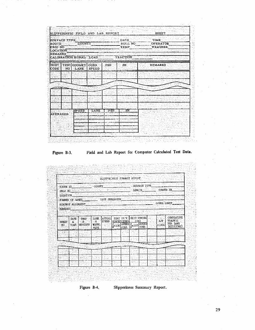
programming, these two forms were simplified to cover most requirements wiih one form (Figure B-3). In the prograll1liling, skid data with the same digit code were averaged. The form "Slipperiness Sull1lilary Report" (Figure Btl) a~comodated the year-to-year or, in some cases, month-to-mpnth average values as well as cumulative traffi~. Average values were also plotted versus cumulative traffic on one of two forms (Figure B-5), de~eqding upon ihe anticipated accumulation of
traffic on the test section. ' ... .
.. c FIELD AND IJiB REPORT . 0~,, "" TEST
TYPE PATE . ROuTE COUNTY ROLL NO .
PROJ NO TEMP ... '
.
"T' S!GNAL: LOAD TRACTION .. _: BY: x_ , .
· .
smm NO. · .
.. TIME . ..
I OPERATOR .. .,· . WllATHER .··
. ...
LOCK-UP: RATE Ren. .
DURATION sec;. . STATIC WHEF.T. LO/lJJ
. · . ..
T~~T
~~= ~~~D f~ ISL~P iSKrfsl) ~s
"" (0:.:~: .. l:ANE ~-AT
E.'""loORR .·
SKID ?urve, ,;., .
. · . .. --
.
.·: .. .
·.·
c-- -----. .
AVERAGES
Figure B-1. Field and Lab Report for Standard Tests .
27

28
SLIPPERINESS l?IEW AND lAB REPORT SURFACE TYPE. ___________ _
ROUTE___ COU>'l'Y ______ _ ffiOJNO ______________ _
LOCATION
TEST ODCMETER TES"T WHEEL SPEED NO Ill.NE PATH TEST
'
JJA1'E_"'~"""',,~--~ ROLL NO~~~--·e-- _
l'EMP ~~~~~~~-~~····
sncc·n no. 'l'TIAE_w~~~--
IEFl, Fln!IT,,, .
. ;.\I (;CC:CJ':C"";'':
.llll!J~ 'j2EMiTXtr"'.N.
~~- ----·--+-+--1··-+-+--~-L .._...,_
SLIPPERINESS FIELD AND 'Liill R.EPOR1' (COJII'£) -.. --..... J.~:.~~:<:..fP., .. ROUTE COUNTY
TES'l' TES1' WHEEL NO LA.NE PATH
vt~iiU~D AT PEAK SLIPING
-.... ·
FIELD 'l."ES1' DA'J'.',
mAGTION , N:;;::~ (;:~;; CKT7s::rTll1l ~~~~~:·r,
I ~'t';~ I BKTD /rwt:~:~n ~~·:,::' ........
... '
Figure B-2. Field and Lab Report for Other than Standard Tests.
lsLIPPERINESS FIELD AND LAB REPORT SHEET
~-URFACE TYPE DATE TIME - ROUT_E COUNTY ROLL NO· OPERATOR
fnOJ NO TEMP WEATHER LOCATION-·
~
REMARKS CALIBRATION SIGNAL:_. LOAD -TRACTION
6:G!T TEST O~OMET CORR PSN SN REMARKS ODE NO LANE SPEED
.
- -- -.;..
SPEED L:ANE PSN SN VERAGES:
Figure ll-3. Field and Lab Report for Computer Calculated Test Data.
S11PPERIN'E.'3S BUMMRY RE?QR.T
ROUTE NO COUNTY SURFACE TYPE
PROJ NO LENGTH CONSTR YR.
LOCATION
NUMBER OF LANES LA.NE .SEPARATOR
RoADNAY ALIGNMENT SPEED LOOT
REMARKS
. .. PATE TEMP JANE ACTUAL PEAK l~~IP SKI~8NUMBER
CUMUlATIVE
SHEET & & & SPEED lhlfThlffiE PSN Aur TRAFFIC
NO TIME WEATHER WHEEL ExlOO SPE~D ;[xlOO SPEE xlOOO PER JANE
PATH w Offil\ w OORR (MILLIOOS)
~
I 11 I lliiJI I 0 Figure ll-4. Slipperiness Summary Report.
29

30
n: id Ul
n:: lJJ [l]
~ -:; c,z
~'::i:~ rn
-:r, ' "
60
50
-;o
~::c)
?0
10
GU
50
40
30
0 2 Ill 12.
';UHYACE TYPE:
C:Oi'\S'L YE:\k PfiOJ!:'~CT NO,:
.
I.
4 14
6 16
LEGEND
Car Equivalent 5-N Trailer SN
13 18
CUMULATIVE TRAFFIC, millions
ROUTE NO.: COUNTY:·
LEYEND
Cat· Equivalent SN T!·ailer SN
20 ---·-----·--!-----+----+----+
Traffh· Lowe
Passing Lane
IJ 0
Passing La1Ho
10 20
-~-0 o~..-____ .J4._ ____ J.e _____ IL.2 ____ ji6 ____ ....Jzo
24 28 32 36 40
CUMULATIVE TRAFFIC, millions
SU!U'/\.CF. TYPE: CONST, Y:Ci'.H:
ROUT:£ NO.: COUNTY:
PftO.JEGT NO.:
Figure ll-5. Forms Used in Plotting SN versus Cumulative Traffic for • Single Test Section.