COMMONLY ENCOUNTERED SEISMIC DESIGN …arch355.cankaya.edu.tr/uploads/files/MASTER TEZI.pdf · Bu...
129
COMMONLY ENCOUNTERED SEISMIC DESIGN FAULTS IN REINFORCED CONCRETE RESIDENTIAL ARCHITECTURE IN TURKEY A THESIS SUBMITTED TO THE GRADUATE SCHOOL OF NATURAL AND APPLIED SCIENCES OF THE MIDDLE EAST TECHNICAL UNIVERSITY BY CENGİZ ÖZMEN IN PARTIAL FULFILLMENT OF THE REQUIREMENTS FOR THE DEGREE OF MASTER OF SCIENCE IN THE DEPARTMENT OF ARCHITECTURE MAY 2002
Transcript of COMMONLY ENCOUNTERED SEISMIC DESIGN …arch355.cankaya.edu.tr/uploads/files/MASTER TEZI.pdf · Bu...
COMMONLY ENCOUNTERED SEISMIC DESIGN FAULTS IN REINFORCED CONCRETE RESIDENTIAL ARCHITECTURE IN TURKEY
A THESIS SUBMITTED TO THE GRADUATE SCHOOL OF NATURAL AND APPLIED SCIENCES
OF THE MIDDLE EAST TECHNICAL UNIVERSITY
BY
CENGİZ ÖZMEN
IN PARTIAL FULFILLMENT OF THE REQUIREMENTS FOR THE DEGREE OF
MASTER OF SCIENCE
IN
THE DEPARTMENT OF ARCHITECTURE
MAY 2002
Approval of the Graduate School of Natural and Applied Sciences.
______________________________
Prof. Dr. Tayfur Öztürk
Director
I certify that this thesis satisfies all the requirements as a thesis for the degree of Master of Science
______________________________
Assoc. Prof. Dr. Selahattin Önür
Head of Department
This is to certify that we have read this thesis and that in our opinion it is fully adequate, in scope and quality, as a thesis for the degree of Master of Science.
______________________________
Assoc. Prof. Dr. Ali İhsan Ünay
Supervisor
Examining Committee Members
Part-time Inst. Dr. Erhan Karaesmen _____________________________
Kayhan Yüceyalçın _____________________________
Inst. Türel Saranlı _____________________________
Part-time Inst. Dr. Coşkun Erkay _____________________________
Assoc. Prof. Dr. Ali İhsan Ünay _____________________________
ABSTRACT
COMMONLY ENCOUNTERED SEISMIC DESIGN FAULTS IN
REINFORCED CONCRETE RESIDENTIAL ARCHITECTURE IN
TURKEY
Özmen, Cengiz
M.S., Department of Architecture
Supervisor: Assoc. Prof. Dr. Ali İhsan Ünay
May 2002, 108 Pages
This thesis is about the architectural design faults, which negatively affect
the structural behavior of reinforced concrete residential buildings during an
earthquake. In Turkey, earthquake resistant design is considered to be under
the responsibility of structural engineers. As a result, architects and
especially students of architecture are not well informed about the effect of
their design decisions on the seismic performance of the buildings. This
thesis will demonstrate that most of the design faults that lead to the
destruction of a building are due to architectural decisions.
iii
This thesis also intends to present the concept of earthquake resistant design
in a comprehensible format for the architects and students of architecture
and therefore aims to contribute to the efforts of creating a better awareness
of earthquake resistant building design.
This thesis begins by explaining the nature of earthquakes and the material
properties of reinforced concrete to create a base of knowledge for the
earthquake resistant design topic. In the fourth chapter, commonly
encountered seismic design faults are explained in a way, which gives
emphasis to the role of the architect. In the fifth chapter, the effects of the
design faults on the seismic performance of the buildings is demonstrated
with the help of computer generated models based on actual collapsed
buildings in İzmit, Bekirpaşa District in 1999 earthquakes.
Keywords: Earthquake Resistant Design, Seismic Design, Seismic Design
Faults, Earthquake Architecture.
iv
ÖZ
TÜRKİYE’DE BETONARME KONUT YAPILARINDA SIKÇA
KARŞILAŞILAN DEPREM TASARIMI HATALARI
Özmen, Cengiz
Yüksek Lisans, Mimarlık Bölümü
Tez Yöneticisi: Assoc. Prof. Dr. Ali İhsan Ünay
Mayıs 2002, 108 sayfa
Bu çalışma, betonarme konut türü yapıların bir deprem sırasındaki strüktürel
davranışlarını olumsuz yönde etkileyen mimari tasarım hatalarını
araştırmaktadır. Türkiye’de depreme dayanıklı yapı tasarımı, inşaat
mühendislerinin sorumluluğu altında görülmektedir, bunun sonucu olarak,
mimarlar ve özellikle mimarlık öğrencileri verdikleri tasarım kararlarının,
tasarladıkları yapıların deprem davranışları üzerindeki etkisi hakkında
yeterli düzeyde bilgi sahibi değillerdir. Bu çalışma, bir binanın yıkılmasına
neden olan hataların çoğunun mimari tasarımdan kaynaklandığını
göstermektedir.
v
Bu çalışma ayrıca depreme dayanıklı yapı tasarımı konusunu mimarların ve
özellikle mimarlık öğrencilerinin anlayabileceği şekilde anlatmaktadır. Bu
sayede halen sürmekte olan, insanları depreme dayanıklı yapı konusunda
bilinçlendrme çalışmalarına bir katkıda bulunmayı hedeflemektedir.
Bu tezde öncelikle depremin genel özellikleri ve betonarmenin malzeme
özellikleri konusunda bilgi verilerek okuyucuda temel bir bilgi birikimi
oluşturmak amaçlanmıştır. Daha sonra sıkça karşılaşılan deprem tasarımı
hataları mimarların sorumlulukları açısından anlatılmıştır. Son olarak İzmit,
Bekirpaşa bölgesinde 1999 depremleri sırasında yıkılan gerçek binalara
dayalı bilgisayar modelleri kullanılarak bu anlatılanların geçerliliği
gösterilmiştir.
Anahtar Kelimeler: Depreme Dayanıklı Tasarım, Sismik Dizayn, Deprem
Tasarımı Hataları, Deprem Mimarlığı.
vi

To My Parents
And
My Grandfather
Kayhan Yüceyalçın
Y. Mühendis Mimar
(Engineer & Architect)
vii

ACKNOWLEDGMENTS
I express heartfelt gratitude to Dr. Erhan Karaesmen for his guidance and
his priceless contribution, which made the field study possible.
I also express sincere appreciation to Dr. Ali İhsan Ünay for his excellent
supervision and insight through the research.
Thanks go to my parents, for their unshakable faith in me, and their
willingness to endure with me the difficulties of my endeavors.
I offer sincere thanks to my grandfather, Kayhan Yüceyalçın, who inspired
me to become an architect.
viii
TABLE OF CONTENTS
ABSTRACT ..................................................................................... iii
ÖZ .................................................................................................... v
ACKNOWLEDGMENTS ................................................................ viii
TABLE OF CONTENTS .................................................................. ix
LIST OF TABLES ............................................................................ xiv
LIST OF FIGURES .......................................................................... xv
LIST OF SYMBOLS ....................................................................... xix
CHAPTER
1. INTRODUCTION ............................................................... 1
1.1 Subject ........................................................................... 1
1.2 Methodology ................................................................... 5
2. EARTHQUAKE .................................................................. 7
2.1 Definition of the Earthquake Phenomenon .................... 7
2.2 Types of Seismic Faults ................................................. 12
2.3 Types of Earthquakes ..................................................... 13
2.3.1 According to the Depth ...................................... 13
2.3.2 According to the Distance .................................. 13
2.3.3 According to the Magnitude ............................... 14
ix
2.3.4 According to the Origin ..................................... 14
2.4 Earthquake Parameters ................................................... 15
2.4.1 Hypocenter .......................................................... 15
2.4.2 Epicenter ............................................................. 15
2.4.3 Focal Depth ........................................................ 16
2.4.4 Isoseismic Map ................................................... 17
2.5 Types of Seismic Waves ................................................ 18
2.6 Intensity of an Earthquake ............................................... 20
2.7 Magnitude of an Earthquake .......................................... 22
2.8 Earthquake Recording Devices ..................................... 23
2.9 Seismic Characteristics of Turkey ................................... 24
3. EARTHQUAKE BEHAVIOR OF REINFORCED
CONCRETE STRUCTURES .............................................. 26
3.1 Properties of Reinforced Concrete .................................. 26
3.2 Essential Definitions in Earthquake-Building
Interaction ....................................................................... 29
3.2.1 Definition of Earthquake Load ........................... 29
3.2.2 Natural Period of a Building ............................... 31
3.2.3 Absorption of Energy ......................................... 33
3.2.4 Effective Ground Acceleration ........................... 34
3.2.5 Ground Structure Interaction .............................. 36
3.3 Fundamental Concepts in Seismic Design ...................... 38
3.3.1 Strength ............................................................... 39
3.3.2 Ductility ............................................................... 39
x
3.3.3 Rigidity ............................................................... 42
3.4 Seismic Design Criteria in Turkey ................................. 43
4. SEISMIC DESIGN FAULTS IN REINFORCED
CONCRETE BUILDINGS .................................................. 44
4.1 Importance of Seismic Resistance in Architectural
Design ............................................................................. 44
4.2 Seismic Design Faults in Plan ........................................ 47
4.2.1 Torsion Eccentricity ............................................ 47
4.2.2 Floor Discontinuities ........................................... 50
4.2.3 Projections in Plan ............................................. 52
4.2.4 Non-Parallel Axis of Structural Elements ........... 54
4.2.5 Fundamental Concepts About Reinforced
Concrete Beams .................................................. 55
4.2.5.1 Non-Continuous Beams ................................ 55
4.2.5.2 Irregular Spans and Beam Cross-Sections .... 56
4.2.5.3 Beam-to-Beam Connections ......................... 57
4.2.5.4 Beam and Frames with Broken Axis ............. 58
4.2.6 Fundamental Concepts About Reinforced
Concrete Slabs .................................................. 59
4.2.6.1 Over-Stretched One-Way Slab ...................... 59
4.2.6.2 Rules About Joist-Slabs ................................. 60
4.2.6.3 Cantilever Slabs ............................................ 62
4.2.7 Fundamental Concepts About R/C Columns ..... 63
4.2.7.1 Columns with Broken Axis ........................... 63
xi
4.2.7.2 Column-to-Beam Connections ...................... 64
4.2.7.3 Column Configuration .................................. 65
4.2.8 Fundamental Concepts About Reinforced Concrete
Shear-Walls ......................................................... 66
4.2.8.1 Location of Shear-Walls ............................... 66
4.2.8.2 Configuration of Shear-Walls ....................... 67
4.3 Seismic Design Faults in Elevation ................................ 68
4.3.1 Weak Storey (Inter-storey Strength) Irregularity . 68
4.3.2 Soft Storey Irregularity ........................................ 70
4.3.3 Discontinuity of Vertical Structural Members .... 72
4.3.4 Irregular Motion of Buildings ............................. 73
4.3.5 The Pounding Effect ............................................ 75
4.3.6 Irregular Distribution of Masses ......................... 77
4.3.7 Short Columns .................................................... 78
4.3.8 Strong Beam-Weak Column Formation .............. 80
4.3.9 Irregularities in Foundation ................................ 82
5. THE EFFECT OF COMMONLY ENCOUNTERED SEISMIC
DESIGN FAULTS ON THE BUILDING STRUCTURE: A
SAMPLE STUDY CONDUCTED WITH COMPUTER
GENERATED STRUCTURAL MODELS .......................... 83
5.1 The Objective of The Study ............................................ 83
5.2 The Scope and The Procedure ......................................... 84
5.3 Computer Models of Defective Buildings ...................... 86
5.3.1 A Residential Building with Irregular Plan ........ 86
xii
5.3.2 A Building with Deficient Column
Configuration ...................................................... 89
5.3.3 Building Model with Soft Storey Formation ....... 92
5.3.4 Building Model with Short-Column Formation .. 95
5.3.5 Building Model with Weak-Storey Formation .... 97
5.3.6 Building Model with Shear-Wall Eccentricity .... 99
5.4 The Results of the Study ................................................. 101
6. CONCLUSION ..................................................................... 102
BIBLIOGRAPHY ....................................................................... 105
xiii
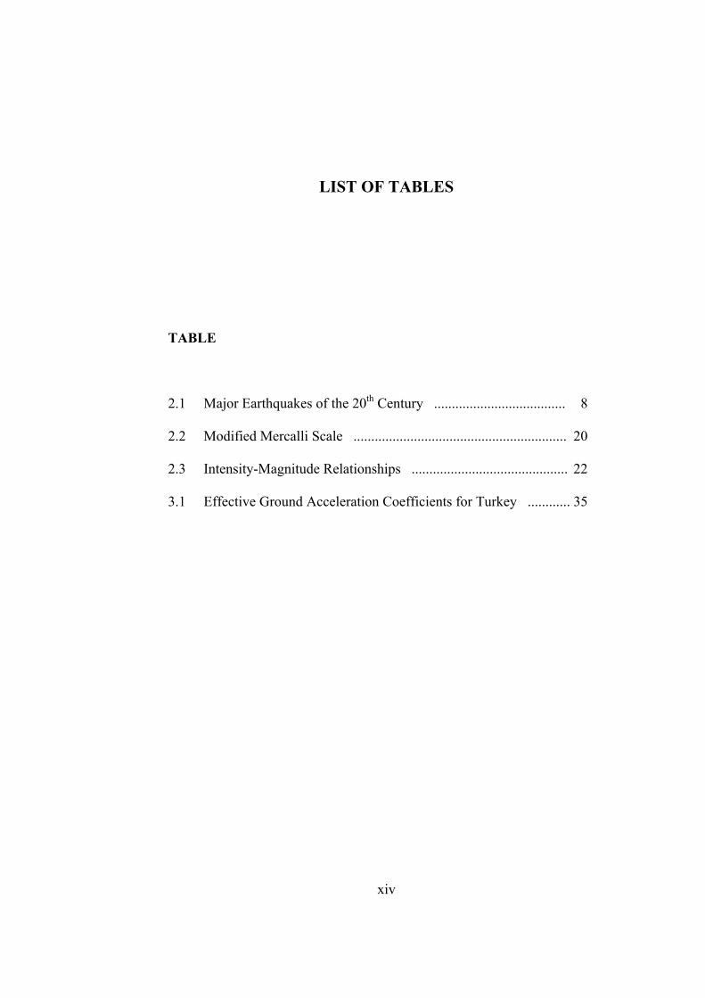
LIST OF TABLES
TABLE
2.1 Major Earthquakes of the 20th Century ..................................... 8
2.2 Modified Mercalli Scale ............................................................ 20
2.3 Intensity-Magnitude Relationships ............................................ 22
3.1 Effective Ground Acceleration Coefficients for Turkey ............ 35
xiv
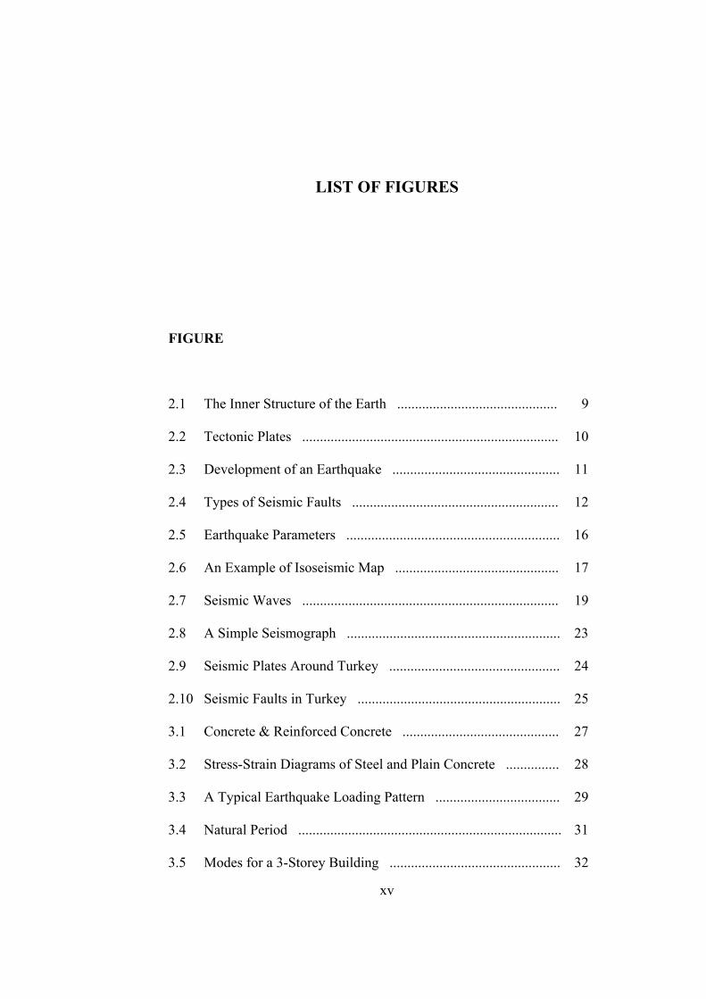
LIST OF FIGURES
FIGURE
2.1 The Inner Structure of the Earth ............................................. 9
2.2 Tectonic Plates ........................................................................ 10
2.3 Development of an Earthquake ............................................... 11
2.4 Types of Seismic Faults .......................................................... 12
2.5 Earthquake Parameters ............................................................ 16
2.6 An Example of Isoseismic Map .............................................. 17
2.7 Seismic Waves ........................................................................ 19
2.8 A Simple Seismograph ............................................................ 23
2.9 Seismic Plates Around Turkey ................................................ 24
2.10 Seismic Faults in Turkey ......................................................... 25
3.1 Concrete & Reinforced Concrete ............................................ 27
3.2 Stress-Strain Diagrams of Steel and Plain Concrete ............... 28
3.3 A Typical Earthquake Loading Pattern ................................... 29
3.4 Natural Period .......................................................................... 31
3.5 Modes for a 3-Storey Building ................................................ 32
xv
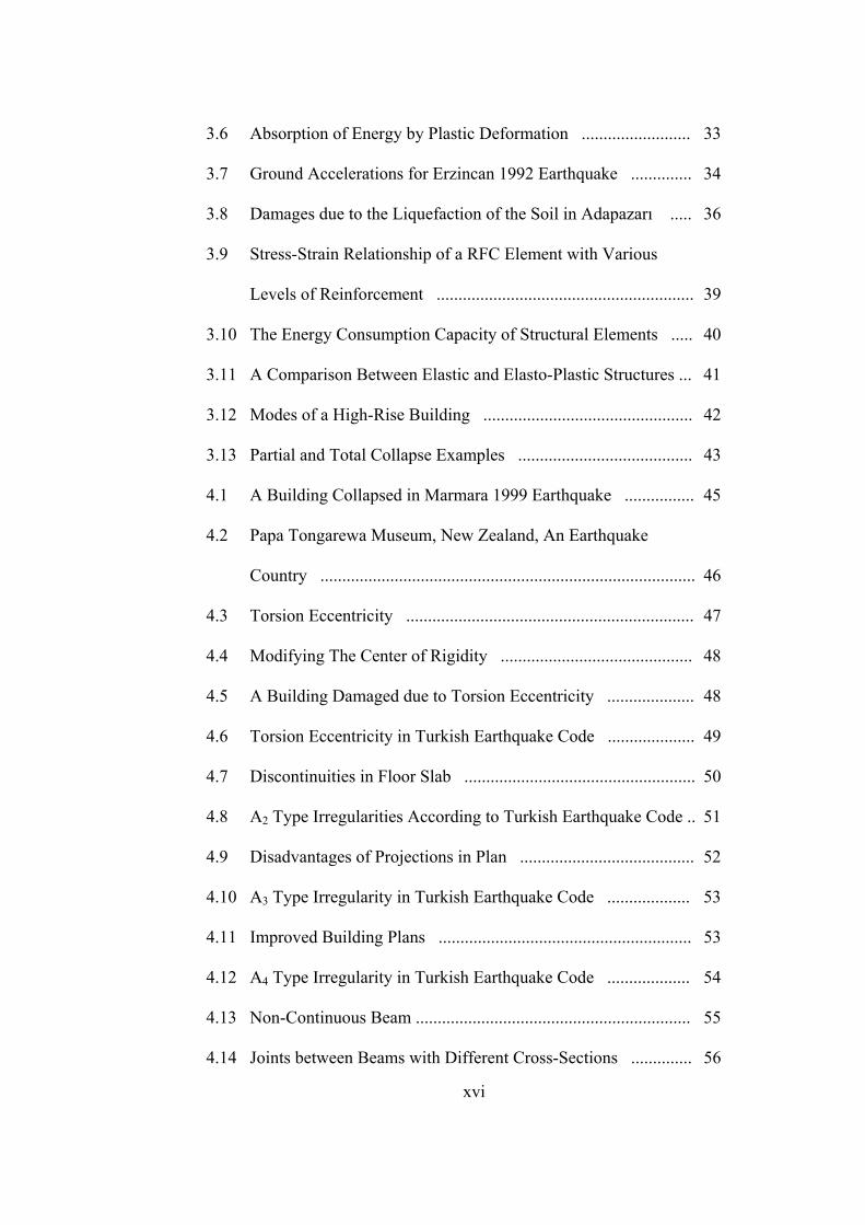
3.6 Absorption of Energy by Plastic Deformation ......................... 33
3.7 Ground Accelerations for Erzincan 1992 Earthquake .............. 34
3.8 Damages due to the Liquefaction of the Soil in Adapazarı ..... 36
3.9 Stress-Strain Relationship of a RFC Element with Various
Levels of Reinforcement ........................................................... 39
3.10 The Energy Consumption Capacity of Structural Elements ..... 40
3.11 A Comparison Between Elastic and Elasto-Plastic Structures ... 41
3.12 Modes of a High-Rise Building ................................................ 42
3.13 Partial and Total Collapse Examples ........................................ 43
4.1 A Building Collapsed in Marmara 1999 Earthquake ................ 45
4.2 Papa Tongarewa Museum, New Zealand, An Earthquake
Country ...................................................................................... 46
4.3 Torsion Eccentricity .................................................................. 47
4.4 Modifying The Center of Rigidity ............................................ 48
4.5 A Building Damaged due to Torsion Eccentricity .................... 48
4.6 Torsion Eccentricity in Turkish Earthquake Code .................... 49
4.7 Discontinuities in Floor Slab ..................................................... 50
4.8 A2 Type Irregularities According to Turkish Earthquake Code .. 51
4.9 Disadvantages of Projections in Plan ........................................ 52
4.10 A3 Type Irregularity in Turkish Earthquake Code ................... 53
4.11 Improved Building Plans .......................................................... 53
4.12 A4 Type Irregularity in Turkish Earthquake Code ................... 54
4.13 Non-Continuous Beam ............................................................... 55
4.14 Joints between Beams with Different Cross-Sections .............. 56
xvi

4.15 Beams Intersecting without Vertical Support ........................... 57
4.16 Beams and Frames with Broken Axis ....................................... 58
4.17 Over-Stretched One-Way Slab .................................................. 59
4.18 Deflection Damage near Shallow Beams in a Block-Joist Slab ... 60
4.19 Irregular Joist-Slab Directions in a Floor .................................. 61
4.20 Cantilever Slabs ........................................................................ 62
4.21 Columns with Broken-Axis ...................................................... 63
4.22 Column-to-Beam Connections and An Example of Damage due
To Weak Column-to-Beam Connection in Marmara 1999
Earthquake ................................................................................ 64
4.23 Irregular vs. Regular Configuration of Columns ...................... 65
4.24 Location of Shear-Walls ........................................................... 66
4.25 Irregular vs. Regular Configuration of Shear-Walls ................ 67
4.26 Weak Storey ............................................................................. 68
4.27 Earthquake Joints in Partition Walls ........................................ 69
4.28 Soft Storey by Deflection Criterion ......................................... 70
4.29 Collapse Mechanism due to Soft Storey .................................. 71
4.30 Discontinuity of Vertical Members in Earthquake Code ......... 72
4.31 The Effect of Building Shape to Seismic Performance ............. 73
4.32 Seismic Design Improvement for Buildings with Several
Blocks ........................................................................................ 74
4.33 Pounding Effect on Adjacent Buildings .................................... 75
4.34 Pounding in Buildings with Different Floor Levels .................. 76
4.35 Irregular Distribution of Masses and Setbacks .......................... 77
xvii
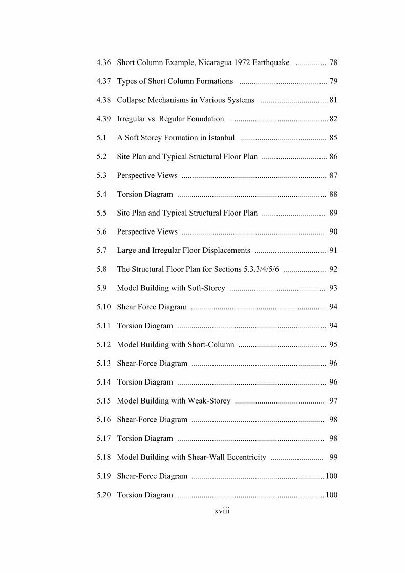
4.36 Short Column Example, Nicaragua 1972 Earthquake ............... 78
4.37 Types of Short Column Formations ........................................... 79
4.38 Collapse Mechanisms in Various Systems ................................. 81
4.39 Irregular vs. Regular Foundation ................................................ 82
5.1 A Soft Storey Formation in İstanbul .......................................... 85
5.2 Site Plan and Typical Structural Floor Plan ................................ 86
5.3 Perspective Views ....................................................................... 87
5.4 Torsion Diagram ......................................................................... 88
5.5 Site Plan and Typical Structural Floor Plan ............................... 89
5.6 Perspective Views ...................................................................... 90
5.7 Large and Irregular Floor Displacements ................................... 91
5.8 The Structural Floor Plan for Sections 5.3.3/4/5/6 ..................... 92
5.9 Model Building with Soft-Storey ............................................... 93
5.10 Shear Force Diagram .................................................................. 94
5.11 Torsion Diagram ......................................................................... 94
5.12 Model Building with Short-Column ........................................... 95
5.13 Shear-Force Diagram .................................................................. 96
5.14 Torsion Diagram ......................................................................... 96
5.15 Model Building with Weak-Storey ............................................ 97
5.16 Shear-Force Diagram ................................................................. 98
5.17 Torsion Diagram ........................................................................ 98
5.18 Model Building with Shear-Wall Eccentricity .......................... 99
5.19 Shear-Force Diagram ................................................................. 100
5.20 Torsion Diagram ........................................................................ 100
xviii
LIST OF SYMBOLS
A Effective ground acceleration
a Acceleration of the building
Ao Effective ground acceleration coefficient
b Column dimension perpendicular to earthquake direction
F Equivalent earthquake force
fck Characteristic strength of concrete
Fe Chemical symbol for Iron
fyk Characteristic yielding strength of steel
g Acceleration due to Earth’s gravity
h Column dimension parallel to earthquake direction
I Moment of inertia of the column
M Magnitude according to Richter Scale
m Mass of the building
Mg Chemical symbol for Magnesium
O Chemical symbol for Oxygen
Si Chemical symbol for Silica
T Natural period of the building
(∆i)max Maximum storey drift
xix
(∆i)average Average storey drift
ηc Shear irregularity coefficient
η∆i Torsion irregularity factor
ηki Displacement coefficient
ΣAe Effective shear area of a floor
ΣAg Total area of columns in a floor
ΣAk Total area of partition walls without door and window openings in
ΣAw Total area of shear-walls in a floor a floor
xx
CHAPTER I
INTRODUCTION
1.1 Subject
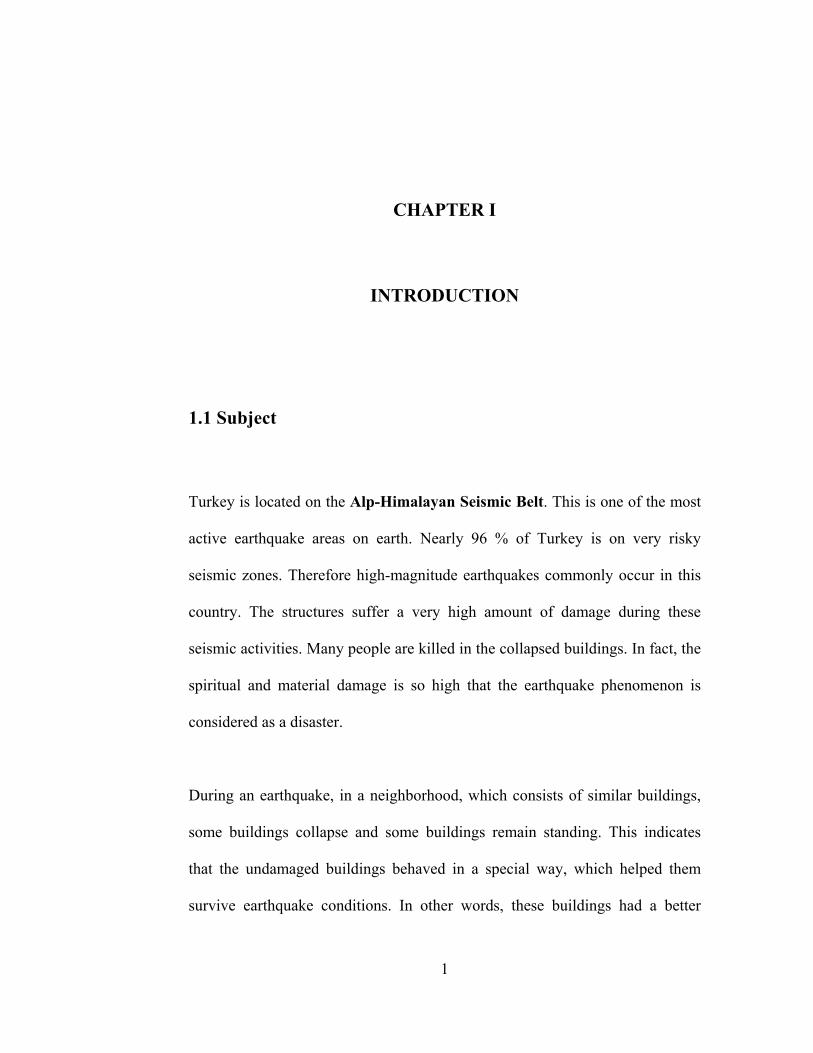
Turkey is located on the Alp-Himalayan Seismic Belt. This is one of the most
active earthquake areas on earth. Nearly 96 % of Turkey is on very risky
seismic zones. Therefore high-magnitude earthquakes commonly occur in this
country. The structures suffer a very high amount of damage during these
seismic activities. Many people are killed in the collapsed buildings. In fact, the
spiritual and material damage is so high that the earthquake phenomenon is
considered as a disaster.
During an earthquake, in a neighborhood, which consists of similar buildings,
some buildings collapse and some buildings remain standing. This indicates
that the undamaged buildings behaved in a special way, which helped them
survive earthquake conditions. In other words, these buildings had a better
1
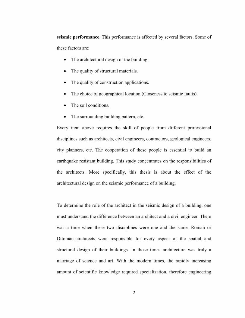
seismic performance. This performance is affected by several factors. Some of
these factors are:
• The architectural design of the building.
• The quality of structural materials.
• The quality of construction applications.
• The choice of geographical location (Closeness to seismic faults).
• The soil conditions.
• The surrounding building pattern, etc.
Every item above requires the skill of people from different professional
disciplines such as architects, civil engineers, contractors, geological engineers,
city planners, etc. The cooperation of these people is essential to build an
earthquake resistant building. This study concentrates on the responsibilities of
the architects. More specifically, this thesis is about the effect of the
architectural design on the seismic performance of a building.
To determine the role of the architect in the seismic design of a building, one
must understand the difference between an architect and a civil engineer. There
was a time when these two disciplines were one and the same. Roman or
Ottoman architects were responsible for every aspect of the spatial and
structural design of their buildings. In those times architecture was truly a
marriage of science and art. With the modern times, the rapidly increasing
amount of scientific knowledge required specialization, therefore engineering
2
was separated from architecture. Engineers concentrated on the structural issues
while the architects focused on the aesthetical, functional and the philosophical
aspects of building design. Doing so the engineers became the scientists and
architects became more and more the artists. The question about the role and
position of architecture is still an issue today. It is no surprise to see that the
schools of architecture function within the schools of fine arts, the departments
of engineering as well as in the form of independent faculties. This confusion
affects the nature and the content of the architectural education.
The definitions of the architect and the civil engineer by Semih S. Tezcan seem
to be close to today’s common understanding. He suggests that the architect is
the master of art who designs a building, which contains certain functions of
life, by the help of technology and artistic creativity. The aim is to provide a
healthy, comfortable and happy environment for the occupants. On the other
hand, the engineer is the specialist who ensures that the structural system
designed by the architect has the necessary strength, durability, and economy
under the external and internal forces.1 Notice the phrase “structural system
designed by the architect”. This is the key idea for this thesis.
The architect decides on all the major design factors affecting the seismic
performance of a structure, such as the shape of the building, the location of
1 Tezcan, Semih. S. Depreme Dayanıklı Yapı İçin Bir Mimarın Seyir Defteri İstanbul: Turkish Earthquake Foundation Pub., 1998, 1-2.
3
every architectural element, the type of the structural system, the configuration
of the structural elements even the preliminary dimensioning of columns and
beams; therefore, no matter what the civil engineer does, the earthquake
behavior of a building is very much a result of the architect’s decisions.
Due to the complexity of the earthquake phenomenon, the reasons of a collapse
are almost unique for every building. However many buildings have collapsed
in a similar way during the earthquakes. Observation showed that these
buildings shared some design characteristics, which negatively affected their
seismic performance. These characteristics are called seismic design faults.
Some of these faults are very common. This indicates that Turkish architects
have a lack of knowledge about the concept of seismic behavior. The aim of
this thesis is to make a classification of these common design faults and present
them in a comprehensible format for the architects.
The target readers of this thesis are the architects and especially the students of
architecture. The results of the research are presented in a format and language
that will help them develop an intuition about the earthquake behavior of their
designs and avoid making simple faults, which will cause a lot of spiritual and
material damage. This thesis hopes to make a contribution to the development
of a higher level of professional quality in architecture.
4
1.2 Methodology
Earthquake resistant building design is a popular research subject in countries
located on active seismic zones. Turkey, being one of them, has a considerable
collection of up-to-date scientific works and publications on this matter;
furthermore, the architectural design aspect of the issue is also investigated
many times. However, because the earthquake resistance topic is believed to be
in the field of engineering in this country, nearly all of the studies are made by
the civil engineers. Naturally, the related theses, papers and publications are
most of the time too technical for the architects. The architectural design issues
are scattered through engineering books. These factors make it difficult for the
architects, who already feel themselves distant to the subject, to reach the
information they need.
The reasons behind the poor seismic performance of the buildings in Turkey are
several. E. Karaesmen makes a general classification of these factors as
follows:
• The universal lack of knowledge in the sciences related with earthquake
engineering.
• The indifference of the public and some members of the engineering
and architecture community towards the earthquake threat.
5
• The ignorance of geological and geo-technical conditions in the choice
of location for urban settlements in countries with fast and undisciplined
city growth.
• The structural defects in masonry buildings due to the general lack of
understanding of this structural system and poor construction quality.
• The structural defects in R/C buildings, which are built on every scale
and everywhere from the remote villages to large urban settlements.
This thesis concentrates on Reinforced Concrete (R/C)2 buildings because R/C
is the dominant structural system in Turkey. Most of the buildings that have
collapsed during the earthquakes were made of R/C. Furthermore 90 % of the
buildings constructed in Turkey are residential buildings. This is why this study
is about the earthquake behavior of this type of building.
The architects are responsible for every aspect of their design. The architect
acts as the coordinator between the different parties involved in the building
project such as, the engineers, the contractors and the client. This role requires
an optimum awareness of all the factors affecting the seismic performance of a
building; however, this study focuses on the responsibilities of the architect as
the designer. What this thesis searches for, are the design faults that are made
on the drawing table of the architect.
2 From this point on the abbreviation R/C will be used for Reinforced Concrete
6
CHAPTER II
EARTHQUAKE
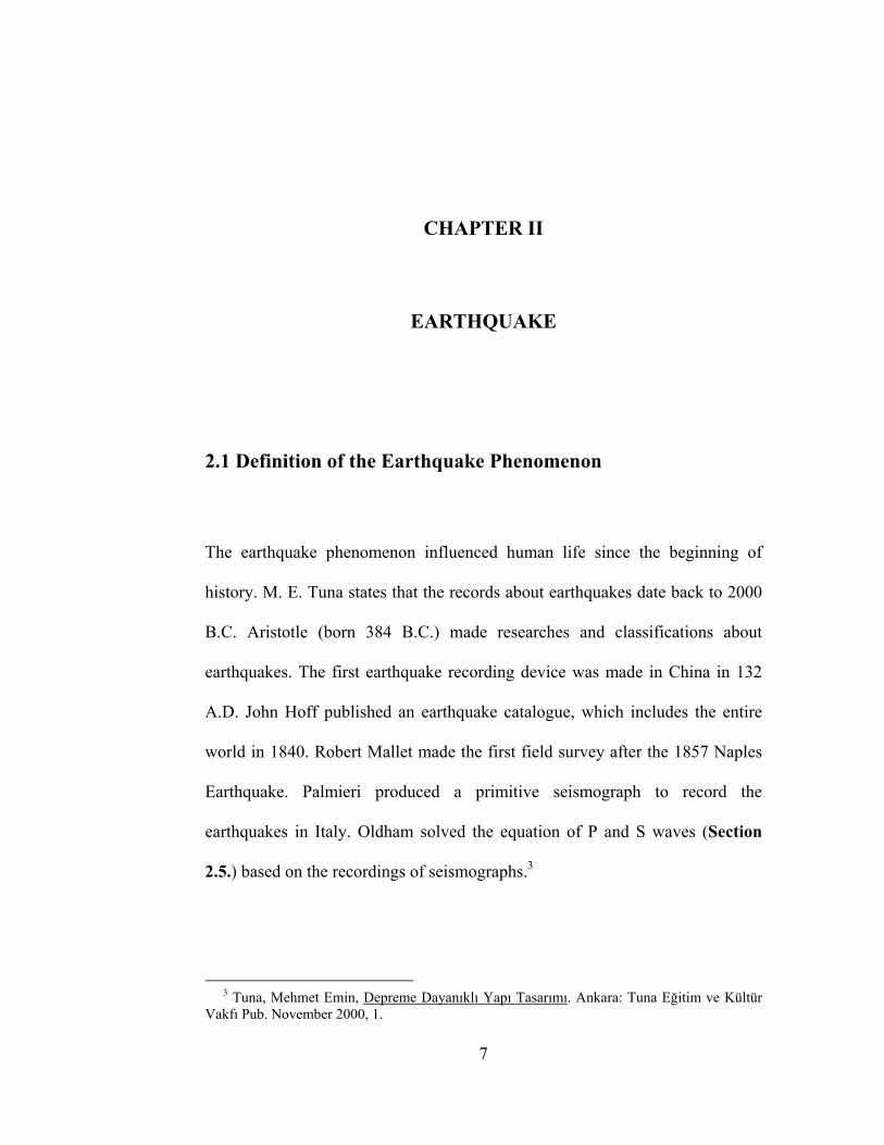
2.1 Definition of the Earthquake Phenomenon
The earthquake phenomenon influenced human life since the beginning of
history. M. E. Tuna states that the records about earthquakes date back to 2000
B.C. Aristotle (born 384 B.C.) made researches and classifications about
earthquakes. The first earthquake recording device was made in China in 132
A.D. John Hoff published an earthquake catalogue, which includes the entire
world in 1840. Robert Mallet made the first field survey after the 1857 Naples
Earthquake. Palmieri produced a primitive seismograph to record the
earthquakes in Italy. Oldham solved the equation of P and S waves (Section
2.5.) based on the recordings of seismographs.3
3 Tuna, Mehmet Emin, Depreme Dayanıklı Yapı Tasarımı. Ankara: Tuna Eğitim ve Kültür Vakfı Pub. November 2000, 1.
7
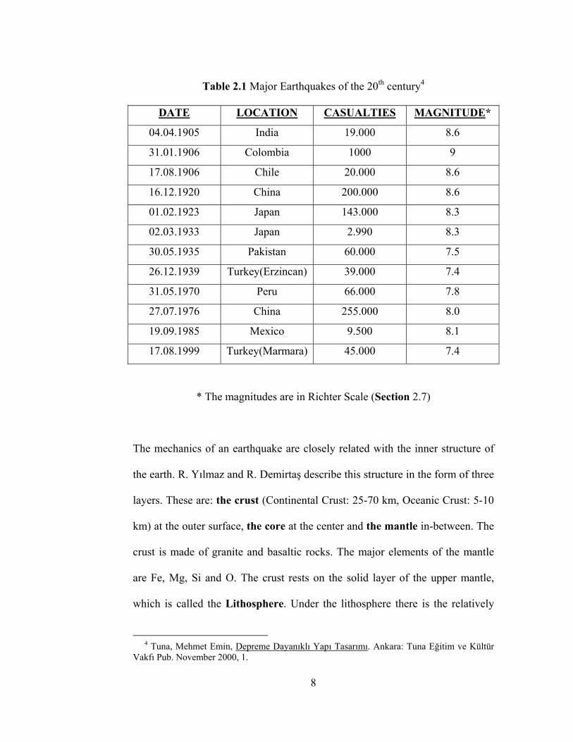
Table 2.1 Major Earthquakes of the 20th century4
DATE LOCATION CASUALTIES MAGNITUDE*
04.04.1905 India 19.000 8.6
31.01.1906 Colombia 1000 9
17.08.1906 Chile 20.000 8.6
16.12.1920 China 200.000 8.6
01.02.1923 Japan 143.000 8.3
02.03.1933 Japan 2.990 8.3
30.05.1935 Pakistan 60.000 7.5
26.12.1939 Turkey(Erzincan) 39.000 7.4
31.05.1970 Peru 66.000 7.8
27.07.1976 China 255.000 8.0
19.09.1985 Mexico 9.500 8.1
17.08.1999 Turkey(Marmara) 45.000 7.4
* The magnitudes are in Richter Scale (Section 2.7)
The mechanics of an earthquake are closely related with the inner structure of
the earth. R. Yılmaz and R. Demirtaş describe this structure in the form of three
layers. These are: the crust (Continental Crust: 25-70 km, Oceanic Crust: 5-10
km) at the outer surface, the core at the center and the mantle in-between. The
crust is made of granite and basaltic rocks. The major elements of the mantle
are Fe, Mg, Si and O. The crust rests on the solid layer of the upper mantle,
which is called the Lithosphere. Under the lithosphere there is the relatively
4 Tuna, Mehmet Emin, Depreme Dayanıklı Yapı Tasarımı. Ankara: Tuna Eğitim ve Kültür Vakfı Pub. November 2000, 1.
8
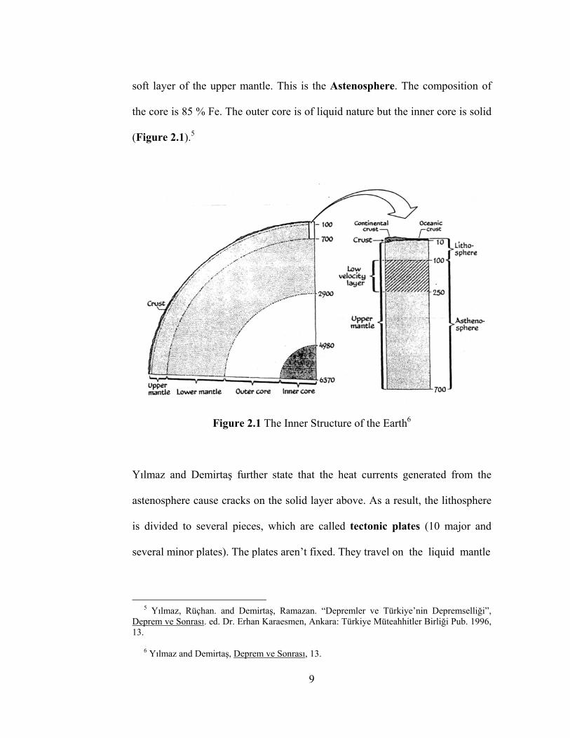
soft layer of the upper mantle. This is the Astenosphere. The composition of
the core is 85 % Fe. The outer core is of liquid nature but the inner core is solid
(Figure 2.1).5
Figure 2.1 The Inner Structure of the Earth6
Yılmaz and Demirtaş further state that the heat currents generated from the
astenosphere cause cracks on the solid layer above. As a result, the lithosphere
is divided to several pieces, which are called tectonic plates (10 major and
several minor plates). The plates aren’t fixed. They travel on the liquid mantle
5 Yılmaz, Rüçhan. and Demirtaş, Ramazan. “Depremler ve Türkiye’nin Depremselliği”, Deprem ve Sonrası. ed. Dr. Erhan Karaesmen, Ankara: Türkiye Müteahhitler Birliği Pub. 1996, 13. 6 Yılmaz and Demirtaş, Deprem ve Sonrası, 13.
9
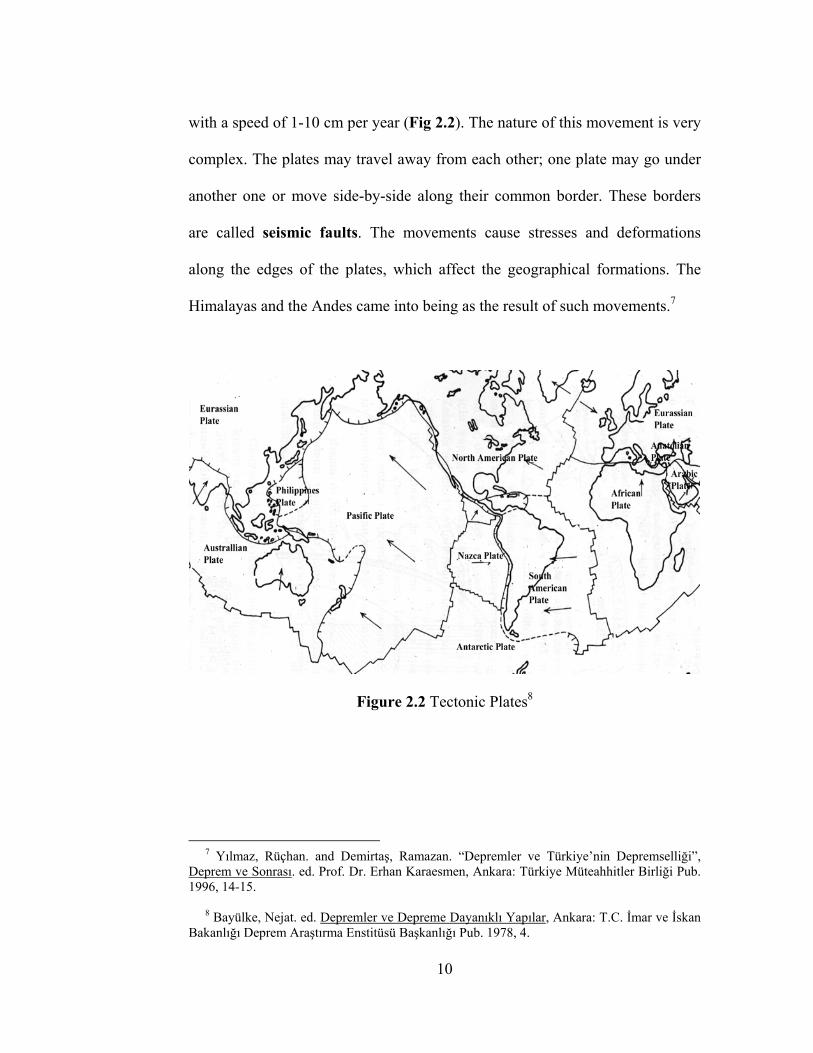
with a speed of 1-10 cm per year (Fig 2.2). The nature of this movement is very
complex. The plates may travel away from each other; one plate may go under
another one or move side-by-side along their common border. These borders
are called seismic faults. The movements cause stresses and deformations
along the edges of the plates, which affect the geographical formations. The
Himalayas and the Andes came into being as the result of such movements.7
Figure 2.2 Tectonic Plates8
7 Yılmaz, Rüçhan. and Demirtaş, Ramazan. “Depremler ve Türkiye’nin Depremselliği”, Deprem ve Sonrası. ed. Prof. Dr. Erhan Karaesmen, Ankara: Türkiye Müteahhitler Birliği Pub. 1996, 14-15. 8 Bayülke, Nejat. ed. Depremler ve Depreme Dayanıklı Yapılar, Ankara: T.C. İmar ve İskan Bakanlığı Deprem Araştırma Enstitüsü Başkanlığı Pub. 1978, 4.
10
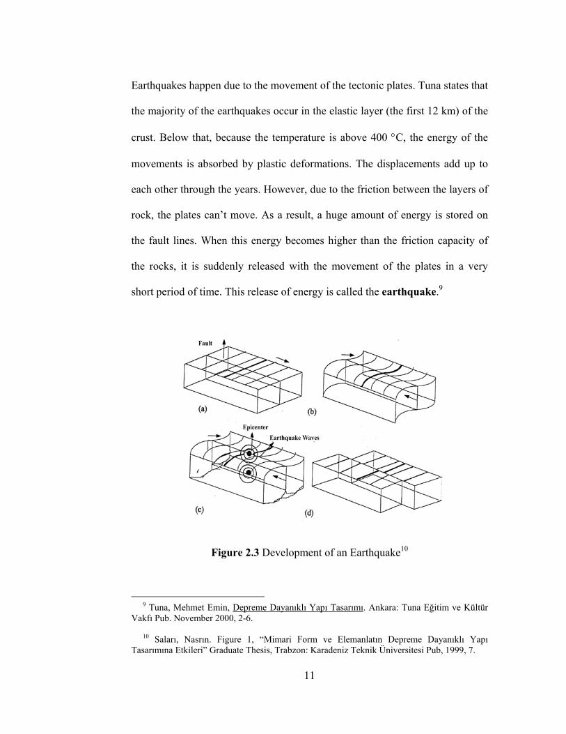
Earthquakes happen due to the movement of the tectonic plates. Tuna states that
the majority of the earthquakes occur in the elastic layer (the first 12 km) of the
crust. Below that, because the temperature is above 400 °C, the energy of the
movements is absorbed by plastic deformations. The displacements add up to
each other through the years. However, due to the friction between the layers of
rock, the plates can’t move. As a result, a huge amount of energy is stored on
the fault lines. When this energy becomes higher than the friction capacity of
the rocks, it is suddenly released with the movement of the plates in a very
short period of time. This release of energy is called the earthquake.9
Figure 2.3 Development of an Earthquake10
9 Tuna, Mehmet Emin, Depreme Dayanıklı Yapı Tasarımı. Ankara: Tuna Eğitim ve Kültür Vakfı Pub. November 2000, 2-6. 10 Saları, Nasrın. Figure 1, “Mimari Form ve Elemanlatın Depreme Dayanıklı Yapı Tasarımına Etkileri” Graduate Thesis, Trabzon: Karadeniz Teknik Üniversitesi Pub, 1999, 7.
11
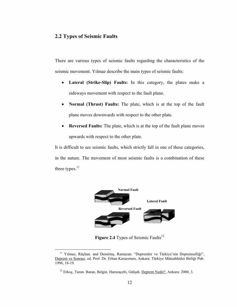
2.2 Types of Seismic Faults
There are various types of seismic faults regarding the characteristics of the
seismic movement. Yılmaz describe the main types of seismic faults:
• Lateral (Strike-Slip) Faults: In this category, the plates make a
sideways movement with respect to the fault plane.
• Normal (Thrust) Faults: The plate, which is at the top of the fault
plane moves downwards with respect to the other plate.
• Reversed Faults: The plate, which is at the top of the fault plane moves
upwards with respect to the other plate.
It is difficult to see seismic faults, which strictly fall in one of these categories,
in the nature. The movement of most seismic faults is a combination of these
three types.11
Figure 2.4 Types of Seismic Faults12
11 Yılmaz, Rüçhan. and Demirtaş, Ramazan. “Depremler ve Türkiye’nin Depremselliği”, Deprem ve Sonrası. ed. Prof. Dr. Erhan Karaesmen, Ankara: Türkiye Müteahhitler Birliği Pub. 1996, 18-19. 12 Erkoç, Turan. Baran, Belgin. Hamzaçebi, Gülşah. Deprem Nedir?, Ankara: 2000, 3.
12
2.3 Types of Earthquakes
2.3.1 According to the depth
The classification made by Erkoç, Baran and Hamzaçebi separates the
earthquakes into the following groups regarding their various properties. First,
according to the depth of the hypocenter (Section 2.4.1): 13
• Shallow Earthquakes: The focal depth is between 0-70 km.
• Medium-Depth Earthquakes: The focal depth is between 71-300 km.
• Deep Earthquakes: The focal depth is between 301-700 km.
The earthquakes that occur in Turkey are mostly shallow. The focal depth
varies between 0 and 30 km.
2.3.2 According to the Distance
The earthquakes can be classified into four groups according to their distance
from the recording devices:
• Local Earthquake: The distance is less than 100 km.
• Proximity Earthquake: The distance is between 100-1000 km.
• Regional Earthquake: The distance is between 1000-5000 km.
• Distant Earthquake: The distance is more than 5000 km. 13 Erkoç, Turan. Baran, Belgin. Hamzaçebi, Gülşah. Deprem Nedir?, Ankara: 2000, 4-5.
13
2.3.3 According to the Magnitude
The earthquakes can be classified into six groups according to their magnitude
(M) in Richter Scale (Section 2.7):
• Very Strong Earthquake: M > 8.0
• Strong Earthquake : 7.0 < M < 8.0
• Medium Earthquake : 5.0 < M < 7.0
• Small Earthquake : 3.0 < M < 5.0
• Micro Earthquake : 1.0 < M < 3.0
• Ultra-Micro Earthquake: M < 1.0
2.3.4 According to the Origin
The Earthquakes can be classified into the following categories by their origin:
• Tectonic Earthquakes: Due to seismic movements.
• Volcanic Earthquakes: Due to volcanic eruptions.
• Subsidence Earthquakes: Due to the collapse of caves and mines
• Non-natural Earthquakes: e.g. nuclear explosions.
14
2.4 Earthquake Parameters
2.4.1 Hypocenter
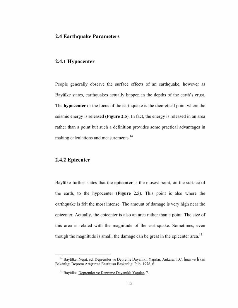
People generally observe the surface effects of an earthquake, however as
Bayülke states, earthquakes actually happen in the depths of the earth’s crust.
The hypocenter or the focus of the earthquake is the theoretical point where the
seismic energy is released (Figure 2.5). In fact, the energy is released in an area
rather than a point but such a definition provides some practical advantages in
making calculations and measurements.14
2.4.2 Epicenter
Bayülke further states that the epicenter is the closest point, on the surface of
the earth, to the hypocenter (Figure 2.5). This point is also where the
earthquake is felt the most intense. The amount of damage is very high near the
epicenter. Actually, the epicenter is also an area rather than a point. The size of
this area is related with the magnitude of the earthquake. Sometimes, even
though the magnitude is small, the damage can be great in the epicenter area.15
14 Bayülke, Nejat. ed. Depremler ve Depreme Dayanıklı Yapılar, Ankara: T.C. İmar ve İskan Bakanlığı Deprem Araştırma Enstitüsü Başkanlığı Pub. 1978, 6. 15 Bayülke, Depremler ve Depreme Dayanıklı Yapılar, 7.
15
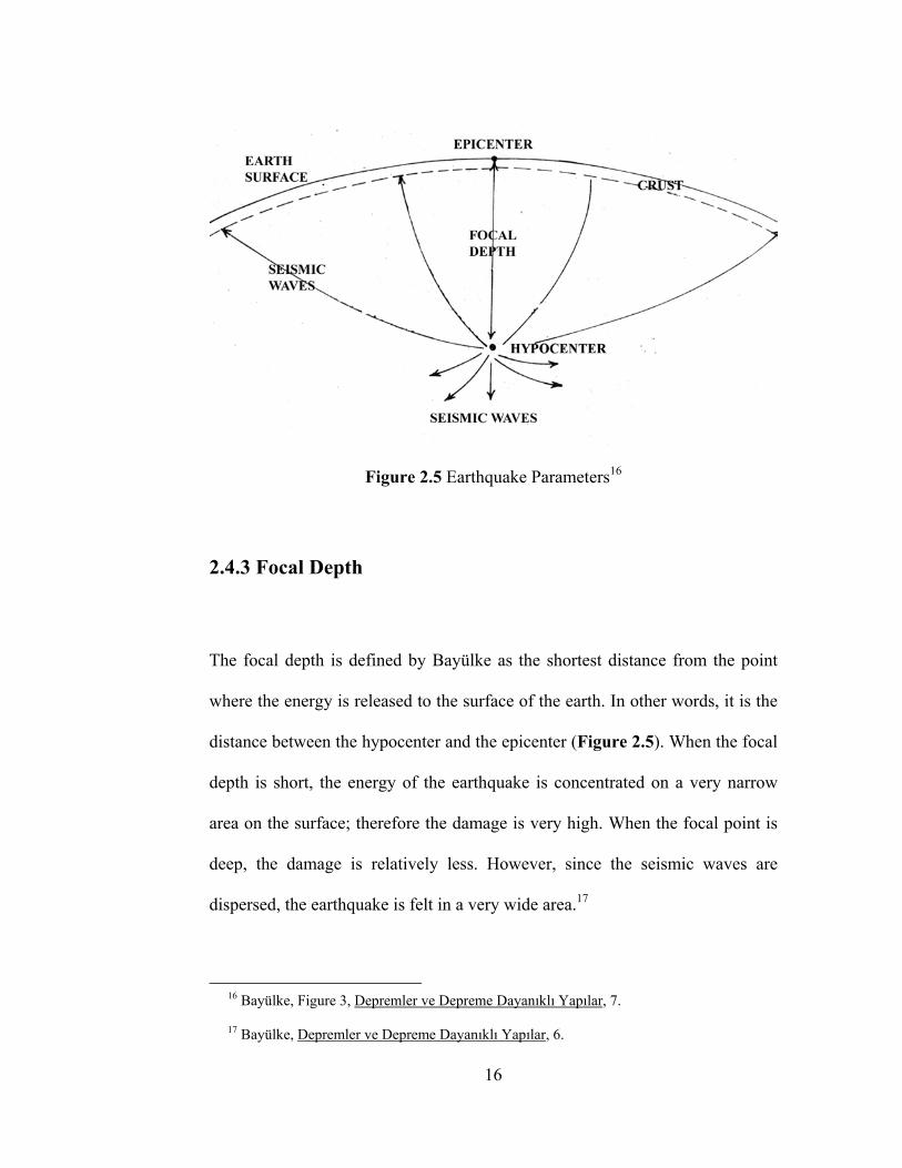
Figure 2.5 Earthquake Parameters16
2.4.3 Focal Depth
The focal depth is defined by Bayülke as the shortest distance from the point
where the energy is released to the surface of the earth. In other words, it is the
distance between the hypocenter and the epicenter (Figure 2.5). When the focal
depth is short, the energy of the earthquake is concentrated on a very narrow
area on the surface; therefore the damage is very high. When the focal point is
deep, the damage is relatively less. However, since the seismic waves are
dispersed, the earthquake is felt in a very wide area.17
16 Bayülke, Figure 3, Depremler ve Depreme Dayanıklı Yapılar, 7. 17 Bayülke, Depremler ve Depreme Dayanıklı Yapılar, 6.
16
2.4.4 Isoseismic Map
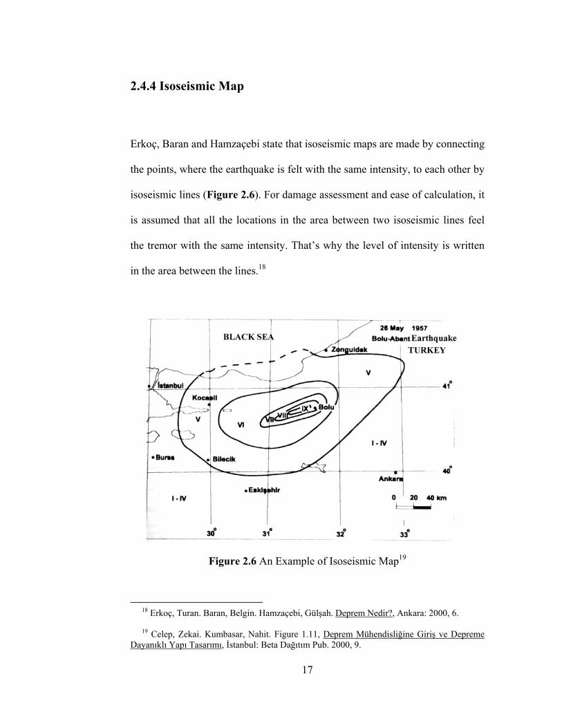
Erkoç, Baran and Hamzaçebi state that isoseismic maps are made by connecting
the points, where the earthquake is felt with the same intensity, to each other by
isoseismic lines (Figure 2.6). For damage assessment and ease of calculation, it
is assumed that all the locations in the area between two isoseismic lines feel
the tremor with the same intensity. That’s why the level of intensity is written
in the area between the lines.18
Figure 2.6 An Example of Isoseismic Map19
18 Erkoç, Turan. Baran, Belgin. Hamzaçebi, Gülşah. Deprem Nedir?, Ankara: 2000, 6. 19 Celep, Zekai. Kumbasar, Nahit. Figure 1.11, Deprem Mühendisliğine Giriş ve Depreme Dayanıklı Yapı Tasarımı, İstanbul: Beta Dağıtım Pub. 2000, 9.
17
2.5 Types of Seismic Waves
After an earthquake various types of waves are propagated. The characteristics
of this propagation are related with the physical and chemical composition of
the rocks. The frequency of some of these waves can be within the hearing
threshold of men. These waves are called the seismic waves (Figure 2.7). These
waves can be classified to three categories according to Saları.20
• Longitudinal Waves: These waves propagate similar to sound waves.
Their speed is around 7-8 km per second. The particles in the earth
vibrate in the same direction with the propagation of the waves. They
are known as the undae primae or the (P) waves because they are the
first waves to reach the measurement stations. These waves can
propagate through solids, liquids and gases.
• Transversal Waves: The particles in the earth vibrate perpendicular to
the propagation direction of the waves. These are the second waves to
arrive the measurement stations; therefore, they are called the undae
secundae or the (S) waves. They can only propagate through solid
objects. Researches have shown that these waves can’t travel through
the earth’s core. That’s why the outer core is assumed to be of liquid
nature.
20 Saları, Nasrın. Figure 1, “Mimari Form ve Elemanların Depreme Dayanıklı Yapı Tasarımına Etkileri” Graduate Thesis, Trabzon: Karadeniz Teknik Üniversitesi Pub, 1999, 10.
18
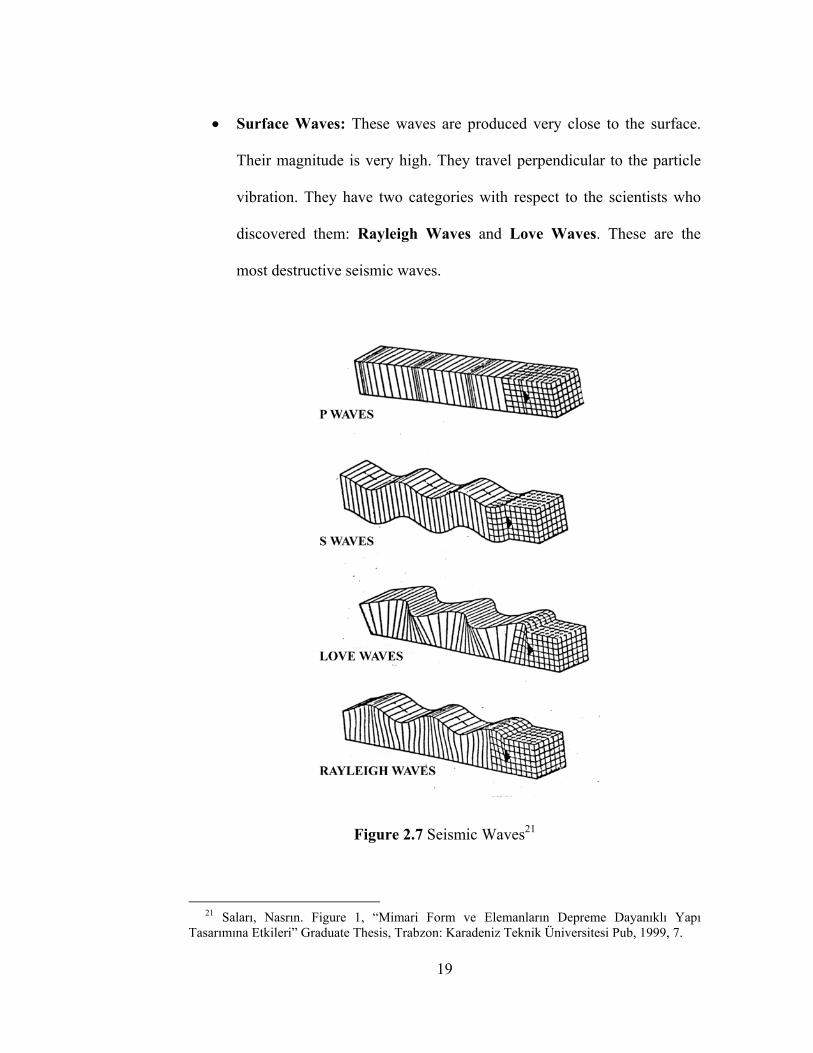
• Surface Waves: These waves are produced very close to the surface.
Their magnitude is very high. They travel perpendicular to the particle
vibration. They have two categories with respect to the scientists who
discovered them: Rayleigh Waves and Love Waves. These are the
most destructive seismic waves.
Figure 2.7 Seismic Waves21
21 Saları, Nasrın. Figure 1, “Mimari Form ve Elemanların Depreme Dayanıklı Yapı Tasarımına Etkileri” Graduate Thesis, Trabzon: Karadeniz Teknik Üniversitesi Pub, 1999, 7.
19
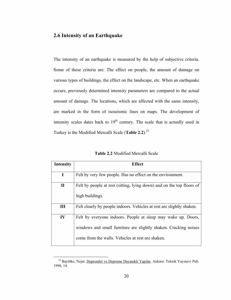
2.6 Intensity of an Earthquake
The intensity of an earthquake is measured by the help of subjective criteria.
Some of these criteria are: The effect on people, the amount of damage on
various types of buildings, the effect on the landscape, etc. When an earthquake
occurs, previously determined intensity parameters are compared to the actual
amount of damage. The locations, which are affected with the same intensity,
are marked in the form of isoseismic lines on maps. The development of
intensity scales dates back to 19th century. The scale that is actually used in
Turkey is the Modified Mercalli Scale (Table 2.2).22
Table 2.2 Modified Mercalli Scale
Intensity Effect
I Felt by very few people. Has no effect on the environment.
II Felt by people at rest (sitting, lying down) and on the top floors of
high buildings.
III Felt clearly by people indoors. Vehicles at rest are slightly shaken.
IV Felt by everyone indoors. People at sleep may wake up. Doors,
windows and small furniture are slightly shaken. Cracking noises
come from the walls. Vehicles at rest are shaken.
22 Bayülke, Nejat. Depremler ve Depreme Dayanıklı Yapılar, Ankara: Teknik Yayınevi Pub. 1998, 14.
20
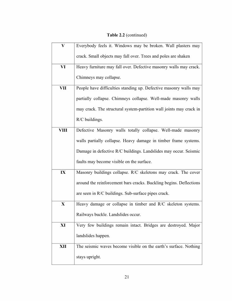
Table 2.2 (continued)
V Everybody feels it. Windows may be broken. Wall plasters may
crack. Small objects may fall over. Trees and poles are shaken
VI Heavy furniture may fall over. Defective masonry walls may crack.
Chimneys may collapse.
VII People have difficulties standing up. Defective masonry walls may
partially collapse. Chimneys collapse. Well-made masonry walls
may crack. The structural system-partition wall joints may crack in
R/C buildings.
VIII Defective Masonry walls totally collapse. Well-made masonry
walls partially collapse. Heavy damage in timber frame systems.
Damage in defective R/C buildings. Landslides may occur. Seismic
faults may become visible on the surface.
IX Masonry buildings collapse. R/C skeletons may crack. The cover
around the reinforcement bars cracks. Buckling begins. Deflections
are seen in R/C buildings. Sub-surface pipes crack.
X Heavy damage or collapse in timber and R/C skeleton systems.
Railways buckle. Landslides occur.
XI Very few buildings remain intact. Bridges are destroyed. Major
landslides happen.
XII The seismic waves become visible on the earth’s surface. Nothing
stays upright.
21
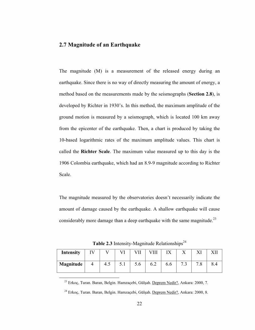
2.7 Magnitude of an Earthquake
The magnitude (M) is a measurement of the released energy during an
earthquake. Since there is no way of directly measuring the amount of energy, a
method based on the measurements made by the seismographs (Section 2.8), is
developed by Richter in 1930’s. In this method, the maximum amplitude of the
ground motion is measured by a seismograph, which is located 100 km away
from the epicenter of the earthquake. Then, a chart is produced by taking the
10-based logarithmic rates of the maximum amplitude values. This chart is
called the Richter Scale. The maximum value measured up to this day is the
1906 Colombia earthquake, which had an 8.9-9 magnitude according to Richter
Scale.
The magnitude measured by the observatories doesn’t necessarily indicate the
amount of damage caused by the earthquake. A shallow earthquake will cause
considerably more damage than a deep earthquake with the same magnitude.23
Table 2.3 Intensity-Magnitude Relationships24
Intensity IV V VI VII VIII IX X XI XII
Magnitude 4 4.5 5.1 5.6 6.2 6.6 7.3 7.8 8.4
23 Erkoç, Turan. Baran, Belgin. Hamzaçebi, Gülşah. Deprem Nedir?, Ankara: 2000, 7. 24 Erkoç, Turan. Baran, Belgin. Hamzaçebi, Gülşah. Deprem Nedir?, Ankara: 2000, 8.
22
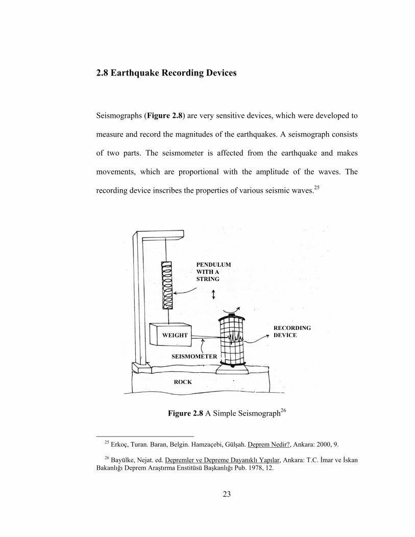
2.8 Earthquake Recording Devices
Seismographs (Figure 2.8) are very sensitive devices, which were developed to
measure and record the magnitudes of the earthquakes. A seismograph consists
of two parts. The seismometer is affected from the earthquake and makes
movements, which are proportional with the amplitude of the waves. The
recording device inscribes the properties of various seismic waves.25
Figure 2.8 A Simple Seismograph26
25 Erkoç, Turan. Baran, Belgin. Hamzaçebi, Gülşah. Deprem Nedir?, Ankara: 2000, 9. 26 Bayülke, Nejat. ed. Depremler ve Depreme Dayanıklı Yapılar, Ankara: T.C. İmar ve İskan Bakanlığı Deprem Araştırma Enstitüsü Başkanlığı Pub. 1978, 12.
23
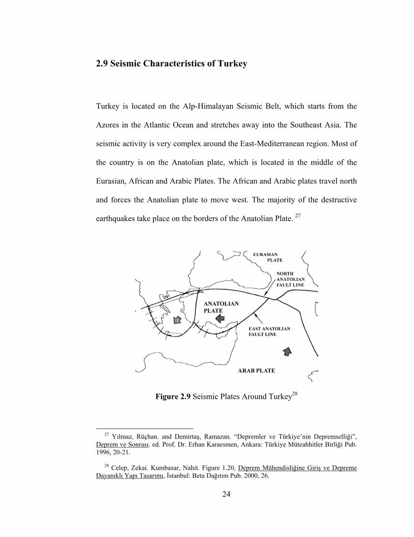
2.9 Seismic Characteristics of Turkey
Turkey is located on the Alp-Himalayan Seismic Belt, which starts from the
Azores in the Atlantic Ocean and stretches away into the Southeast Asia. The
seismic activity is very complex around the East-Mediterranean region. Most of
the country is on the Anatolian plate, which is located in the middle of the
Eurasian, African and Arabic Plates. The African and Arabic plates travel north
and forces the Anatolian plate to move west. The majority of the destructive
earthquakes take place on the borders of the Anatolian Plate. 27
Figure 2.9 Seismic Plates Around Turkey28
27 Yılmaz, Rüçhan. and Demirtaş, Ramazan. “Depremler ve Türkiye’nin Depremselliği”, Deprem ve Sonrası. ed. Prof. Dr. Erhan Karaesmen, Ankara: Türkiye Müteahhitler Birliği Pub. 1996, 20-21. 28 Celep, Zekai. Kumbasar, Nahit. Figure 1.20, Deprem Mühendisliğine Giriş ve Depreme Dayanıklı Yapı Tasarımı, İstanbul: Beta Dağıtım Pub. 2000, 26.
24
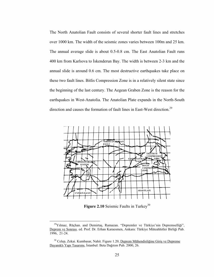
The North Anatolian Fault consists of several shorter fault lines and stretches
over 1000 km. The width of the seismic zones varies between 100m and 25 km.
The annual average slide is about 0.5-0.8 cm. The East Anatolian Fault runs
400 km from Karlıova to İskenderun Bay. The width is between 2-3 km and the
annual slide is around 0.6 cm. The most destructive earthquakes take place on
these two fault lines. Bitlis Compression Zone is in a relatively silent state since
the beginning of the last century. The Aegean Graben Zone is the reason for the
earthquakes in West-Anatolia. The Anatolian Plate expands in the North-South
direction and causes the formation of fault lines in East-West direction.29
Figure 2.10 Seismic Faults in Turkey30
29Yılmaz, Rüçhan. and Demirtaş, Ramazan. “Depremler ve Türkiye’nin Depremselliği”, Deprem ve Sonrası. ed. Prof. Dr. Erhan Karaesmen, Ankara: Türkiye Müteahhitler Birliği Pub. 1996, 21-24. 30 Celep, Zekai. Kumbasar, Nahit. Figure 1.20, Deprem Mühendisliğine Giriş ve Depreme Dayanıklı Yapı Tasarımı, İstanbul: Beta Dağıtım Pub. 2000, 26.
25
CHAPTER III
EARTHQUAKE BEHAVIOR OF REINFORCED CONCRETE
STRUCTURES
3.1 Properties of Reinforced Concrete
Reinforced concrete is the dominant building material in Turkey. It is necessary
to have some basic knowledge about the material properties of R/C to
understand its seismic behavior. Atımtay states that R/C is a composite
material. It is made of concrete, which is very strong in compression forces but
weak in tension forces, and steel, which is strong, both in compression and
tension forces. The steel is used in the form of bars with circular cross-sections.
These bars are called reinforcing bars. The reinforcing bars are used where
tension forces occur, to compensate the tensile weakness of concrete.31
31 Atımtay, Ergin. Reinforced Concrete Fundamentals, Ankara: Bizim Büro Basımevi Pub., February 1998, 3.
26
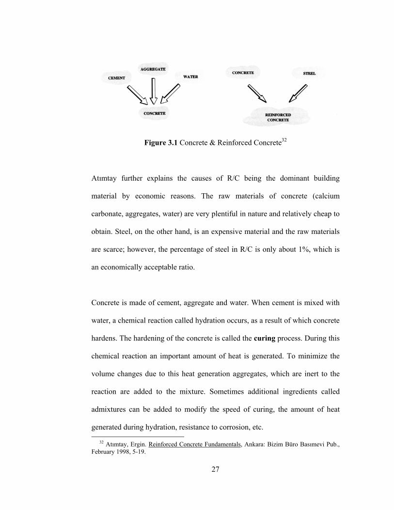
Figure 3.1 Concrete & Reinforced Concrete32
Atımtay further explains the causes of R/C being the dominant building
material by economic reasons. The raw materials of concrete (calcium
carbonate, aggregates, water) are very plentiful in nature and relatively cheap to
obtain. Steel, on the other hand, is an expensive material and the raw materials
are scarce; however, the percentage of steel in R/C is only about 1%, which is
an economically acceptable ratio.
Concrete is made of cement, aggregate and water. When cement is mixed with
water, a chemical reaction called hydration occurs, as a result of which concrete
hardens. The hardening of the concrete is called the curing process. During this
chemical reaction an important amount of heat is generated. To minimize the
volume changes due to this heat generation aggregates, which are inert to the
reaction are added to the mixture. Sometimes additional ingredients called
admixtures can be added to modify the speed of curing, the amount of heat
generated during hydration, resistance to corrosion, etc. 32 Atımtay, Ergin. Reinforced Concrete Fundamentals, Ankara: Bizim Büro Basımevi Pub., February 1998, 5-19.
27
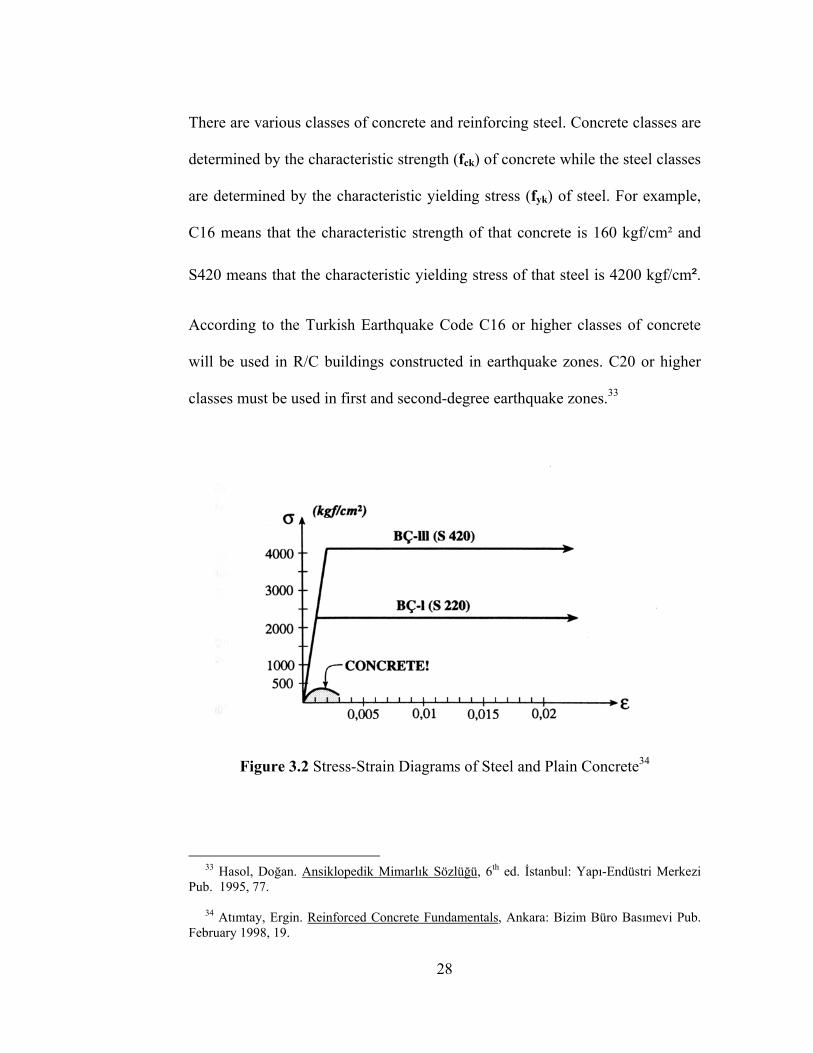
There are various classes of concrete and reinforcing steel. Concrete classes are
determined by the characteristic strength (fck) of concrete while the steel classes
are determined by the characteristic yielding stress (fyk) of steel. For example,
C16 means that the characteristic strength of that concrete is 160 kgf/cm² and
S420 means that the characteristic yielding stress of that steel is 4200 kgf/cm².
According to the Turkish Earthquake Code C16 or higher classes of concrete
will be used in R/C buildings constructed in earthquake zones. C20 or higher
classes must be used in first and second-degree earthquake zones.33
Figure 3.2 Stress-Strain Diagrams of Steel and Plain Concrete34
33 Hasol, Doğan. Ansiklopedik Mimarlık Sözlüğü, 6th ed. İstanbul: Yapı-Endüstri Merkezi Pub. 1995, 77. 34 Atımtay, Ergin. Reinforced Concrete Fundamentals, Ankara: Bizim Büro Basımevi Pub. February 1998, 19.
28
3.2 Essential Definitions in Earthquake-Building Interaction
3.2.1 Definition of Earthquake Load
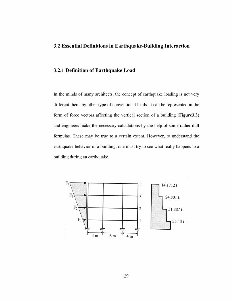
In the minds of many architects, the concept of earthquake loading is not very
different then any other type of conventional loads. It can be represented in the
form of force vectors affecting the vertical section of a building (Figure3.3)
and engineers make the necessary calculations by the help of some rather dull
formulas. These may be true to a certain extent. However, to understand the
earthquake behavior of a building, one must try to see what really happens to a
building during an earthquake.
29
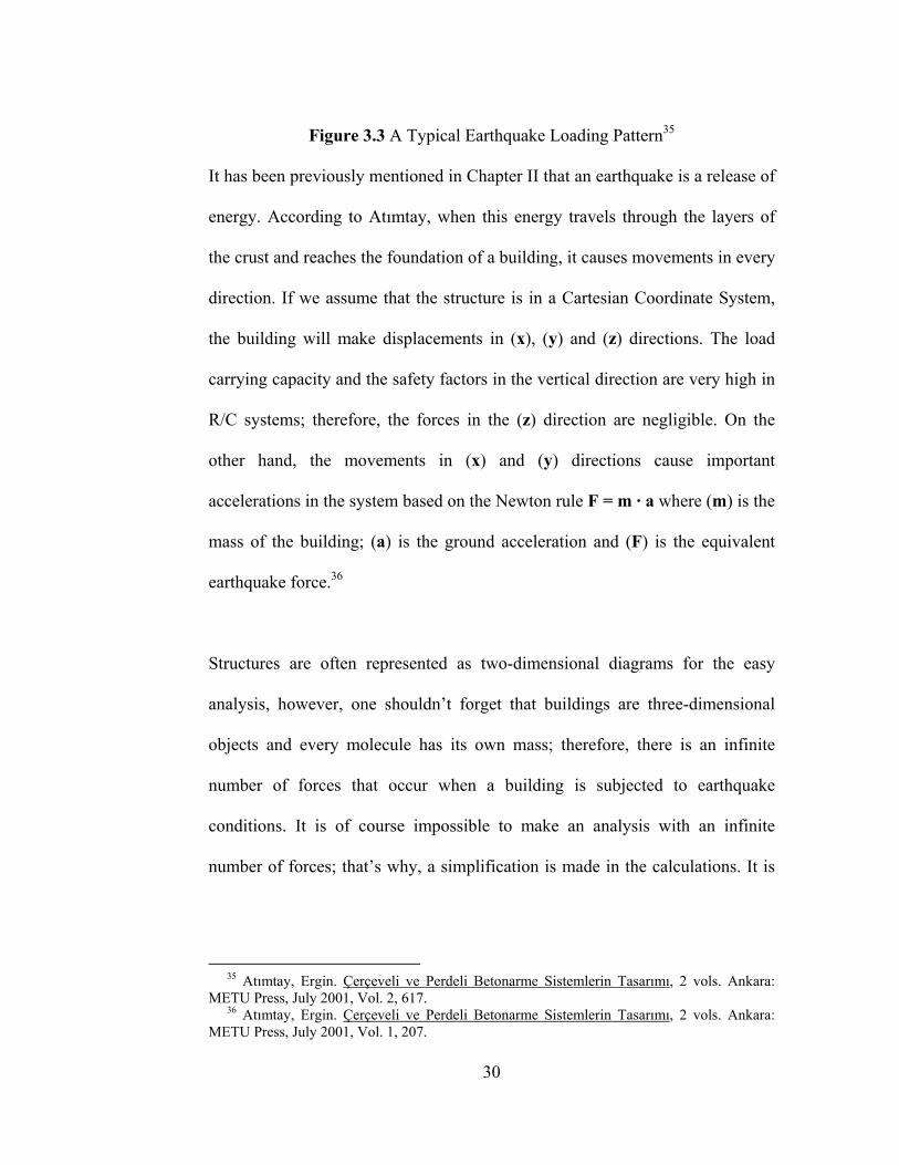
Figure 3.3 A Typical Earthquake Loading Pattern35
It has been previously mentioned in Chapter II that an earthquake is a release of
energy. According to Atımtay, when this energy travels through the layers of
the crust and reaches the foundation of a building, it causes movements in every
direction. If we assume that the structure is in a Cartesian Coordinate System,
the building will make displacements in (x), (y) and (z) directions. The load
carrying capacity and the safety factors in the vertical direction are very high in
R/C systems; therefore, the forces in the (z) direction are negligible. On the
other hand, the movements in (x) and (y) directions cause important
accelerations in the system based on the Newton rule F = m · a where (m) is the
mass of the building; (a) is the ground acceleration and (F) is the equivalent
earthquake force.36
Structures are often represented as two-dimensional diagrams for the easy
analysis, however, one shouldn’t forget that buildings are three-dimensional
objects and every molecule has its own mass; therefore, there is an infinite
number of forces that occur when a building is subjected to earthquake
conditions. It is of course impossible to make an analysis with an infinite
number of forces; that’s why, a simplification is made in the calculations. It is
35 Atımtay, Ergin. Çerçeveli ve Perdeli Betonarme Sistemlerin Tasarımı, 2 vols. Ankara: METU Press, July 2001, Vol. 2, 617. 36 Atımtay, Ergin. Çerçeveli ve Perdeli Betonarme Sistemlerin Tasarımı, 2 vols. Ankara: METU Press, July 2001, Vol. 1, 207.
30
assumed that every floor has its own mass and that the weights of columns,
partition walls, etc. are effective on a floor-by-floor basis.
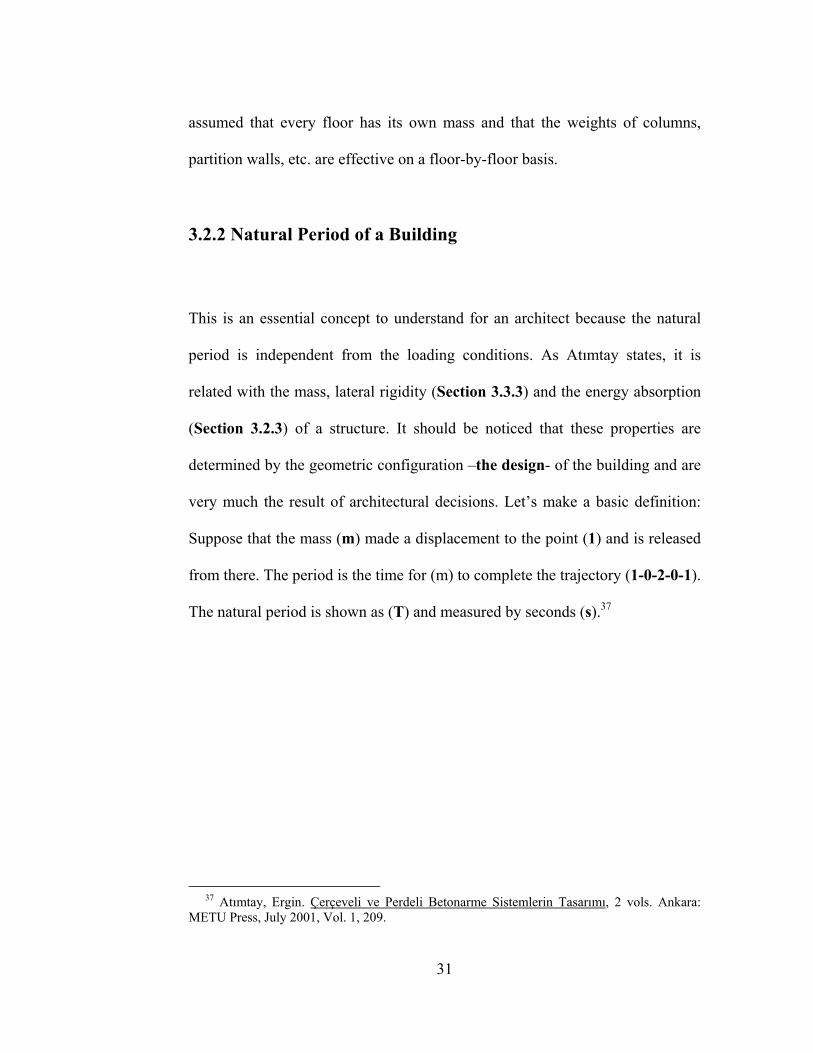
3.2.2 Natural Period of a Building
This is an essential concept to understand for an architect because the natural
period is independent from the loading conditions. As Atımtay states, it is
related with the mass, lateral rigidity (Section 3.3.3) and the energy absorption
(Section 3.2.3) of a structure. It should be noticed that these properties are
determined by the geometric configuration –the design- of the building and are
very much the result of architectural decisions. Let’s make a basic definition:
Suppose that the mass (m) made a displacement to the point (1) and is released
from there. The period is the time for (m) to complete the trajectory (1-0-2-0-1).
The natural period is shown as (T) and measured by seconds (s).37
37 Atımtay, Ergin. Çerçeveli ve Perdeli Betonarme Sistemlerin Tasarımı, 2 vols. Ankara: METU Press, July 2001, Vol. 1, 209.
31
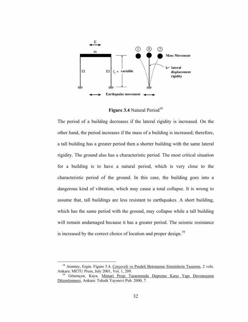
Figure 3.4 Natural Period38
The period of a building decreases if the lateral rigidity is increased. On the
other hand, the period increases if the mass of a building is increased; therefore,
a tall building has a greater period then a shorter building with the same lateral
rigidity. The ground also has a characteristic period. The most critical situation
for a building is to have a natural period, which is very close to the
characteristic period of the ground. In this case, the building goes into a
dangerous kind of vibration, which may cause a total collapse. It is wrong to
assume that, tall buildings are less resistant to earthquakes. A short building,
which has the same period with the ground, may collapse while a tall building
will remain undamaged because it has a greater period. The seismic resistance
is increased by the correct choice of location and proper design.39
38 Atımtay, Ergin. Figure 5.4, Çerçeveli ve Perdeli Betonarme Sistemlerin Tasarımı, 2 vols. Ankara: METU Press, July 2001, Vol. 1, 209. 39 Gönençen, Kaya. Mimari Proje Tasarımında Depreme Karşı Yapı Davranışının Düzenlenmesi, Ankara: Teknik Yayınevi Pub. 2000, 7.
32
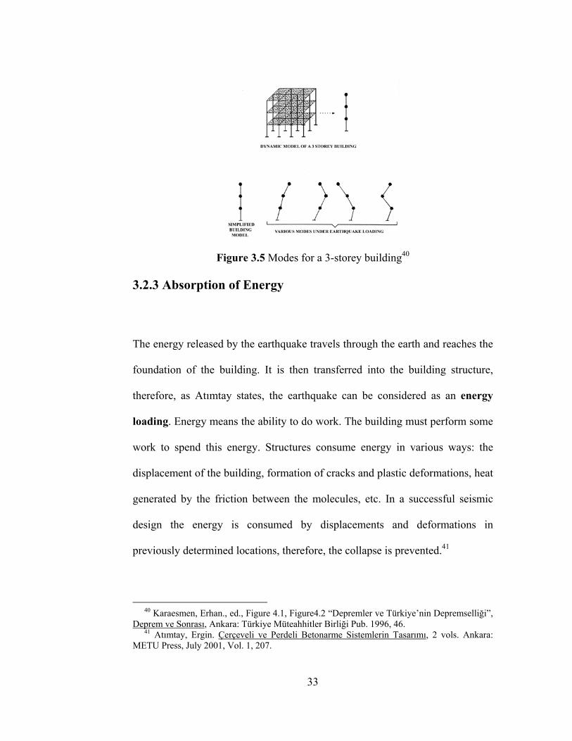
Figure 3.5 Modes for a 3-storey building40
3.2.3 Absorption of Energy
The energy released by the earthquake travels through the earth and reaches the
foundation of the building. It is then transferred into the building structure,
therefore, as Atımtay states, the earthquake can be considered as an energy
loading. Energy means the ability to do work. The building must perform some
work to spend this energy. Structures consume energy in various ways: the
displacement of the building, formation of cracks and plastic deformations, heat
generated by the friction between the molecules, etc. In a successful seismic
design the energy is consumed by displacements and deformations in
previously determined locations, therefore, the collapse is prevented.41
40 Karaesmen, Erhan., ed., Figure 4.1, Figure4.2 “Depremler ve Türkiye’nin Depremselliği”, Deprem ve Sonrası, Ankara: Türkiye Müteahhitler Birliği Pub. 1996, 46. 41 Atımtay, Ergin. Çerçeveli ve Perdeli Betonarme Sistemlerin Tasarımı, 2 vols. Ankara: METU Press, July 2001, Vol. 1, 207.
33
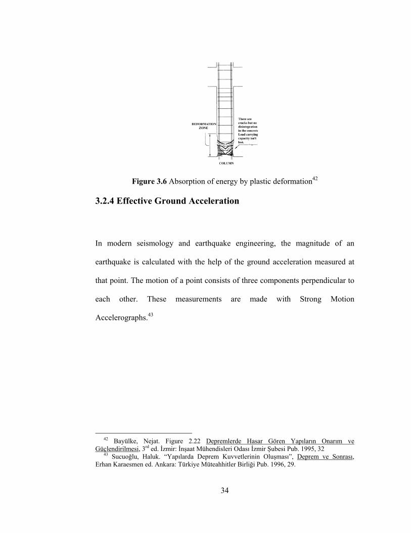
Figure 3.6 Absorption of energy by plastic deformation42
3.2.4 Effective Ground Acceleration
In modern seismology and earthquake engineering, the magnitude of an
earthquake is calculated with the help of the ground acceleration measured at
that point. The motion of a point consists of three components perpendicular to
each other. These measurements are made with Strong Motion
Accelerographs.43
42 Bayülke, Nejat. Figure 2.22 Depremlerde Hasar Gören Yapıların Onarım ve Güçlendirilmesi, 3rd ed. İzmir: İnşaat Mühendisleri Odası İzmir Şubesi Pub. 1995, 32 43 Sucuoğlu, Haluk. “Yapılarda Deprem Kuvvetlerinin Oluşması”, Deprem ve Sonrası, Erhan Karaesmen ed. Ankara: Türkiye Müteahhitler Birliği Pub. 1996, 29.
34
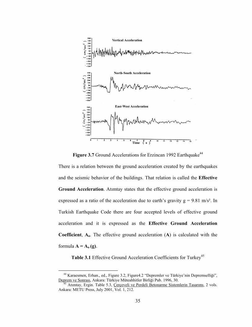
Figure 3.7 Ground Accelerations for Erzincan 1992 Earthquake44
There is a relation between the ground acceleration created by the earthquakes
and the seismic behavior of the buildings. That relation is called the Effective
Ground Acceleration. Atımtay states that the effective ground acceleration is
expressed as a ratio of the acceleration due to earth’s gravity g = 9.81 m/s². In
Turkish Earthquake Code there are four accepted levels of effective ground
acceleration and it is expressed as the Effective Ground Acceleration
Coefficient, Ao. The effective ground acceleration (A) is calculated with the
formula A = Ao (g).
Table 3.1 Effective Ground Acceleration Coefficients for Turkey45
44 Karaesmen, Erhan., ed., Figure 3.2, Figure4.2 “Depremler ve Türkiye’nin Depremselliği”, Deprem ve Sonrası, Ankara: Türkiye Müteahhitler Birliği Pub. 1996, 30. 45 Atımtay, Ergin. Table 5.3, Çerçeveli ve Perdeli Betonarme Sistemlerin Tasarımı, 2 vols. Ankara: METU Press, July 2001, Vol. 1, 212.
35
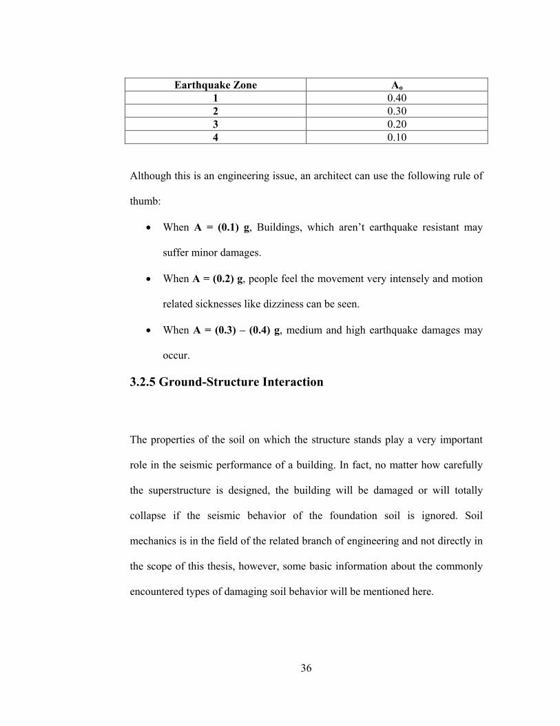
Earthquake Zone Ao 1 0.40 2 0.30 3 0.20 4 0.10
Although this is an engineering issue, an architect can use the following rule of
thumb:
• When A = (0.1) g, Buildings, which aren’t earthquake resistant may
suffer minor damages.
• When A = (0.2) g, people feel the movement very intensely and motion
related sicknesses like dizziness can be seen.
• When A = (0.3) – (0.4) g, medium and high earthquake damages may
occur.
3.2.5 Ground-Structure Interaction
The properties of the soil on which the structure stands play a very important
role in the seismic performance of a building. In fact, no matter how carefully
the superstructure is designed, the building will be damaged or will totally
collapse if the seismic behavior of the foundation soil is ignored. Soil
mechanics is in the field of the related branch of engineering and not directly in
the scope of this thesis, however, some basic information about the commonly
encountered types of damaging soil behavior will be mentioned here.
36
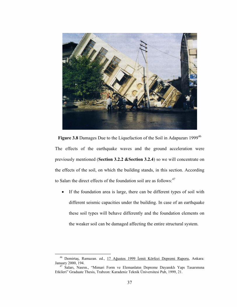
Figure 3.8 Damages Due to the Liquefaction of the Soil in Adapazarı 199946
The effects of the earthquake waves and the ground acceleration were
previously mentioned (Section 3.2.2 &Section 3.2.4) so we will concentrate on
the effects of the soil, on which the building stands, in this section. According
to Saları the direct effects of the foundation soil are as follows:47
• If the foundation area is large, there can be different types of soil with
different seismic capacities under the building. In case of an earthquake
these soil types will behave differently and the foundation elements on
the weaker soil can be damaged affecting the entire structural system.
46 Demirtaş, Ramazan. ed., 17 Ağustos 1999 İzmit Körfezi Depremi Raporu, Ankara: January 2000, 194. 47 Saları, Nasrın., “Mimari Form ve Elemanlatın Depreme Dayanıklı Yapı Tasarımına Etkileri” Graduate Thesis, Trabzon: Karadeniz Teknik Üniversitesi Pub, 1999, 21.
37
• Cracks may occur in the foundation soil due to the earthquake
displacements. These cracks may cause important and sometimes fatal
deformations in the structural system of the building.
• A very important and destructive soil phenomenon is the liquefaction
(Figure 3.8). Especially in sandy soils and filled grounds, which haven’t
completed their settlements, the load carrying capacity is based only on
the friction between the particles. During an earthquake, the water
pressure increases and separates the grains from each other, therefore,
the load carrying capacity is compromised and the ground acts like a
liquid.
• Landslides may occur due to the unforeseen movements of the water in
the layers of earth. Soil may turn into mud and act like a liquid. There is
especially great risk on inclined sites.
3.3 Fundamental Concepts in Seismic Design
The concepts that were mentioned so far were either related with the nature of
the earthquake phenomenon or with the effects of the environmental factors on
a building. In this section however, the fundamental properties, which the R/C
structure itself has to possess to be resistant to earthquake loading will be seen.
These properties are:
• Strength
• Ductility
38
• Rigidity
3.3.1 Strength
The first condition for a R/C structure to perform well in any kind of situation is
that the materials in the structural system should have both individually and
collectively the necessary cross-sections to resist the calculated loads. The
architectural and engineering projects must be prepared according to the proper
technical criteria –in this case the Turkish Earthquake Code- and the
applications in the construction site must be in conformity with the projects.48
3.3.2 Ductility
Ductility is the most critical characteristic of a R/C structure against the lateral
loads such as the earthquake loading. Ductility is the ability of the structure to
consume energy with elastic displacements and plastic deformations. While
doing this, the structure shouldn’t have an important loss in its load-carrying
capacity. Ductility of a R/C structure is closely related with the percentage of
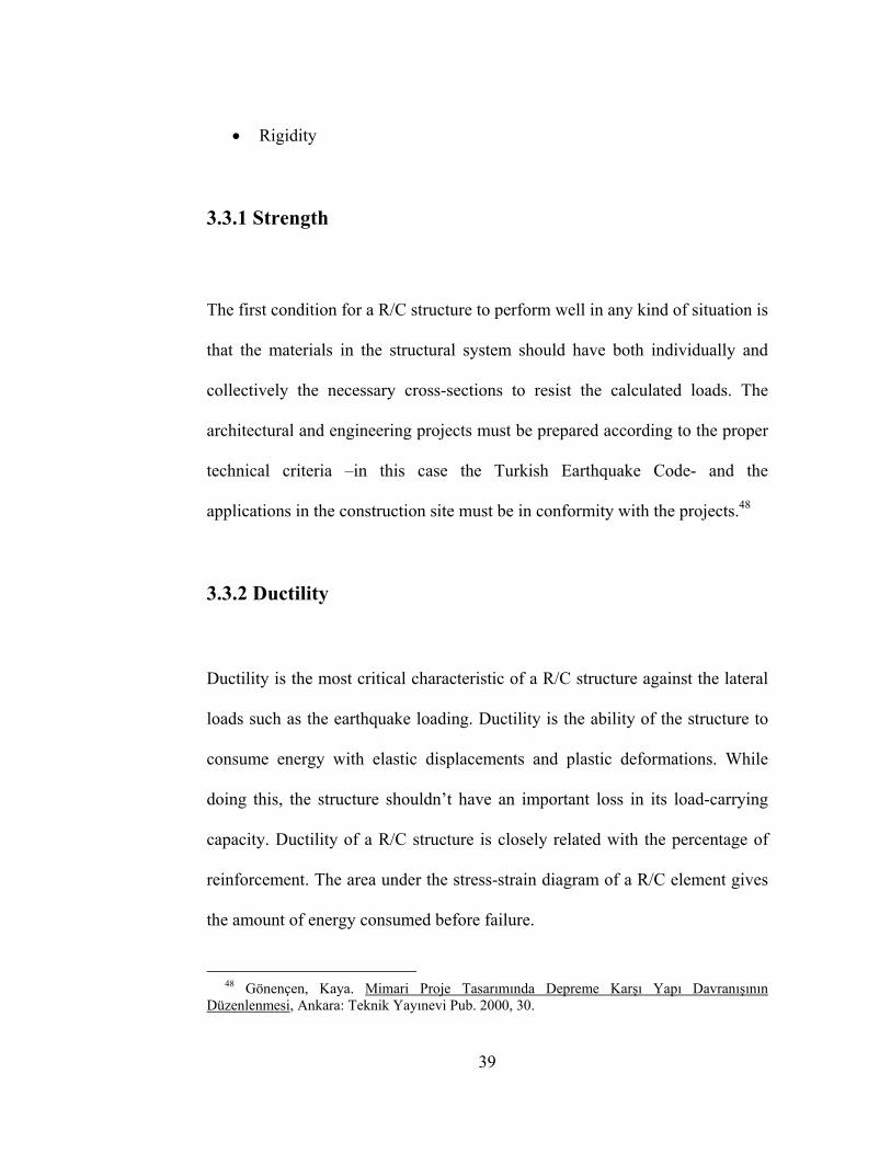
reinforcement. The area under the stress-strain diagram of a R/C element gives
the amount of energy consumed before failure.
48 Gönençen, Kaya. Mimari Proje Tasarımında Depreme Karşı Yapı Davranışının Düzenlenmesi, Ankara: Teknik Yayınevi Pub. 2000, 30.
39
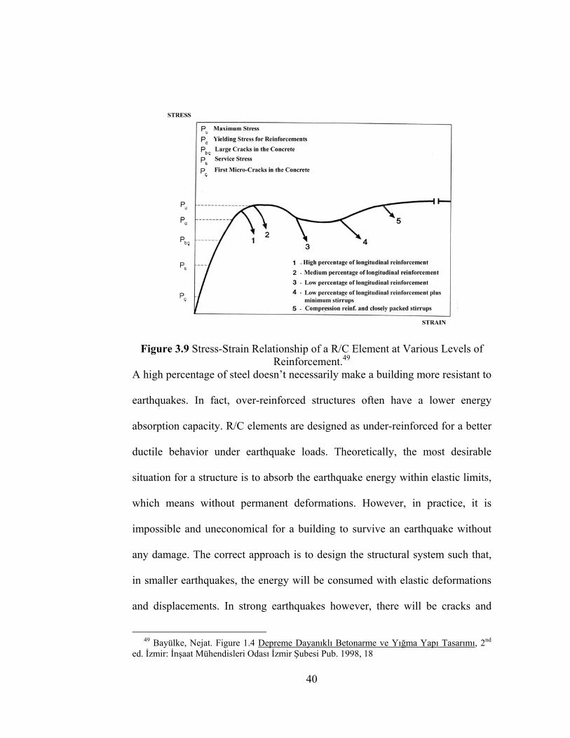
Figure 3.9 Stress-Strain Relationship of a R/C Element at Various Levels of Reinforcement.49
A high percentage of steel doesn’t necessarily make a building more resistant to
earthquakes. In fact, over-reinforced structures often have a lower energy
absorption capacity. R/C elements are designed as under-reinforced for a better
ductile behavior under earthquake loads. Theoretically, the most desirable
situation for a structure is to absorb the earthquake energy within elastic limits,
which means without permanent deformations. However, in practice, it is
impossible and uneconomical for a building to survive an earthquake without
any damage. The correct approach is to design the structural system such that,
in smaller earthquakes, the energy will be consumed with elastic deformations
and displacements. In strong earthquakes however, there will be cracks and
49 Bayülke, Nejat. Figure 1.4 Depreme Dayanıklı Betonarme ve Yığma Yapı Tasarımı, 2nd ed. İzmir: İnşaat Mühendisleri Odası İzmir Şubesi Pub. 1998, 18
40
plastic deformations in structural joints without compromising the load-
carrying capacity. The building may be severely damaged but it will not
collapse and the loss of lives will be prevented.
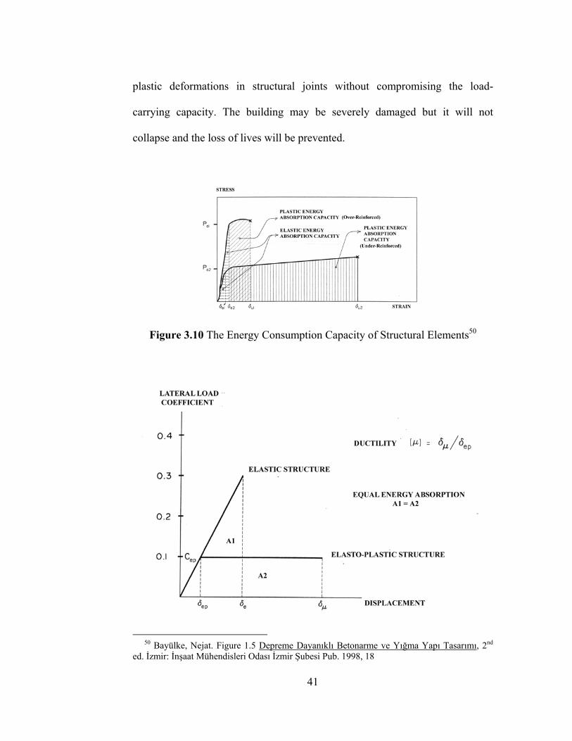
Figure 3.10 The Energy Consumption Capacity of Structural Elements50
50 Bayülke, Nejat. Figure 1.5 Depreme Dayanıklı Betonarme ve Yığma Yapı Tasarımı, 2nd ed. İzmir: İnşaat Mühendisleri Odası İzmir Şubesi Pub. 1998, 18
41
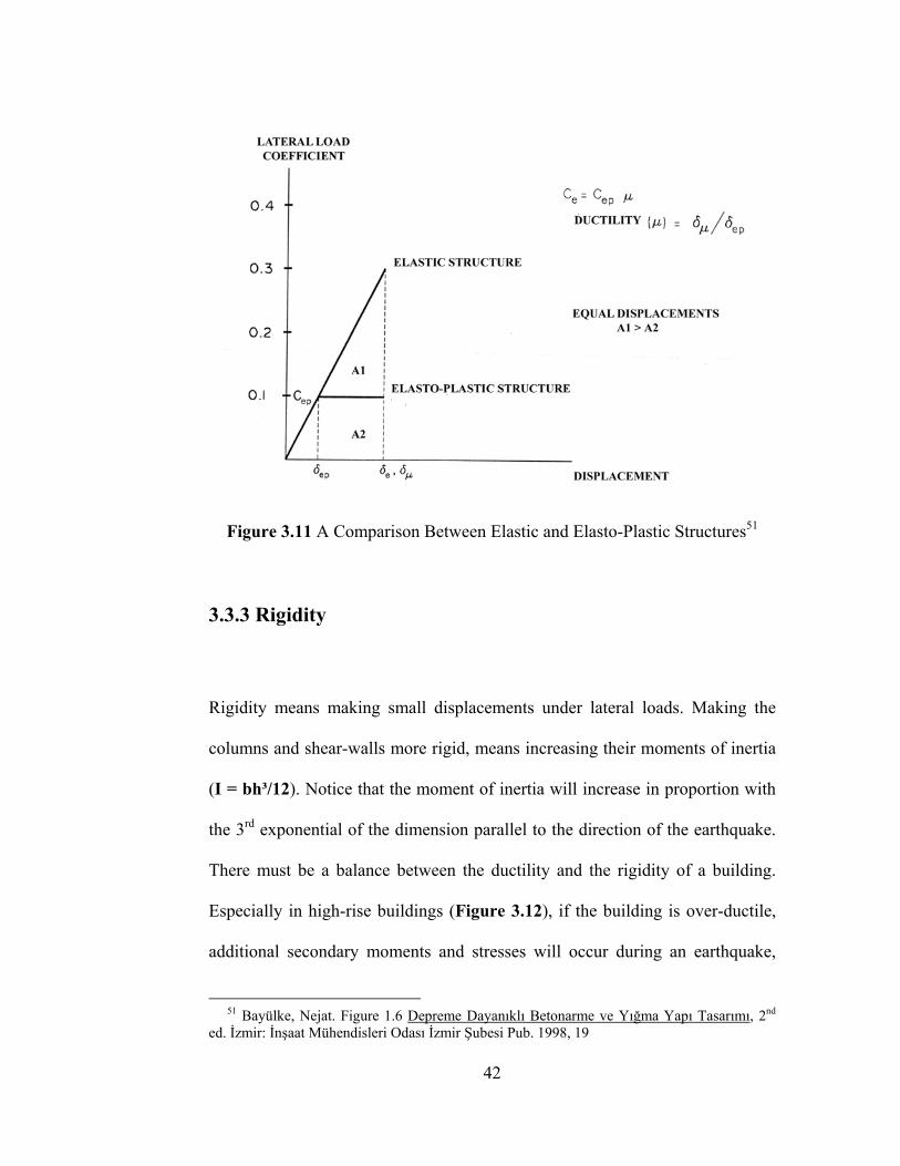
Figure 3.11 A Comparison Between Elastic and Elasto-Plastic Structures51
3.3.3 Rigidity
Rigidity means making small displacements under lateral loads. Making the
columns and shear-walls more rigid, means increasing their moments of inertia
(I = bh³/12). Notice that the moment of inertia will increase in proportion with
the 3rd exponential of the dimension parallel to the direction of the earthquake.
There must be a balance between the ductility and the rigidity of a building.
Especially in high-rise buildings (Figure 3.12), if the building is over-ductile,
additional secondary moments and stresses will occur during an earthquake,
51 Bayülke, Nejat. Figure 1.6 Depreme Dayanıklı Betonarme ve Yığma Yapı Tasarımı, 2nd ed. İzmir: İnşaat Mühendisleri Odası İzmir Şubesi Pub. 1998, 19
42
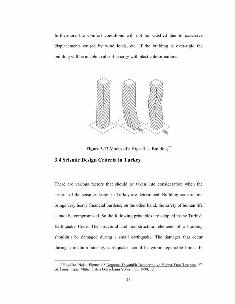
furthermore the comfort conditions will not be satisfied due to excessive
displacements caused by wind loads, etc. If the building is over-rigid the
building will be unable to absorb energy with plastic deformations.
Figure 3.12 Modes of a High-Rise Building52
3.4 Seismic Design Criteria in Turkey
There are various factors that should be taken into consideration when the
criteria of the seismic design in Turkey are determined. Building construction
brings very heavy financial burdens; on the other hand, the safety of human life
cannot be compromised. So the following principles are adopted in the Turkish
Earthquake Code. The structural and non-structural elements of a building
shouldn’t be damaged during a small earthquake. The damages that occur
during a medium-intensity earthquake should be within repairable limits. In
52 Bayülke, Nejat. Figure 1.2 Depreme Dayanıklı Betonarme ve Yığma Yapı Tasarımı, 2nd ed. İzmir: İnşaat Mühendisleri Odası İzmir Şubesi Pub. 1998, 12
43
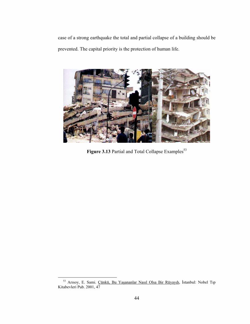
case of a strong earthquake the total and partial collapse of a building should be
prevented. The capital priority is the protection of human life.
Figure 3.13 Partial and Total Collapse Examples53
53 Arısoy, E. Sami. Çünkü, Bu Yaşananlar Nasıl Olsa Bir Rüyaydı, İstanbul: Nobel Tıp Kitabevleri Pub. 2001, 47
44

CHAPTER IV
SEISMIC DESIGN FAULTS IN REINFORCED CONCRETE
BUILDINGS
4.1 Importance of Seismic Resistance in Architectural Design
For a society, which is committed to create a better environment for the present
and future generations, there are significant lessons to be learned from the
devastations of past earthquakes. It is very unfortunate for Turkey to be on an
active seismic as it suffers from the spiritual and economic losses. However, it
is also lucky in a sense because the scenes of damaged and collapsed buildings
offer a unique natural laboratory, which no money can buy; furthermore, it
allows the scientists to make first-hand observations and test the validity of the
existing theories. It is the professional and ethical responsibility of the
architects to participate in these efforts of research and observation to be able to
better understand the seismic behavior of the buildings they design.
44
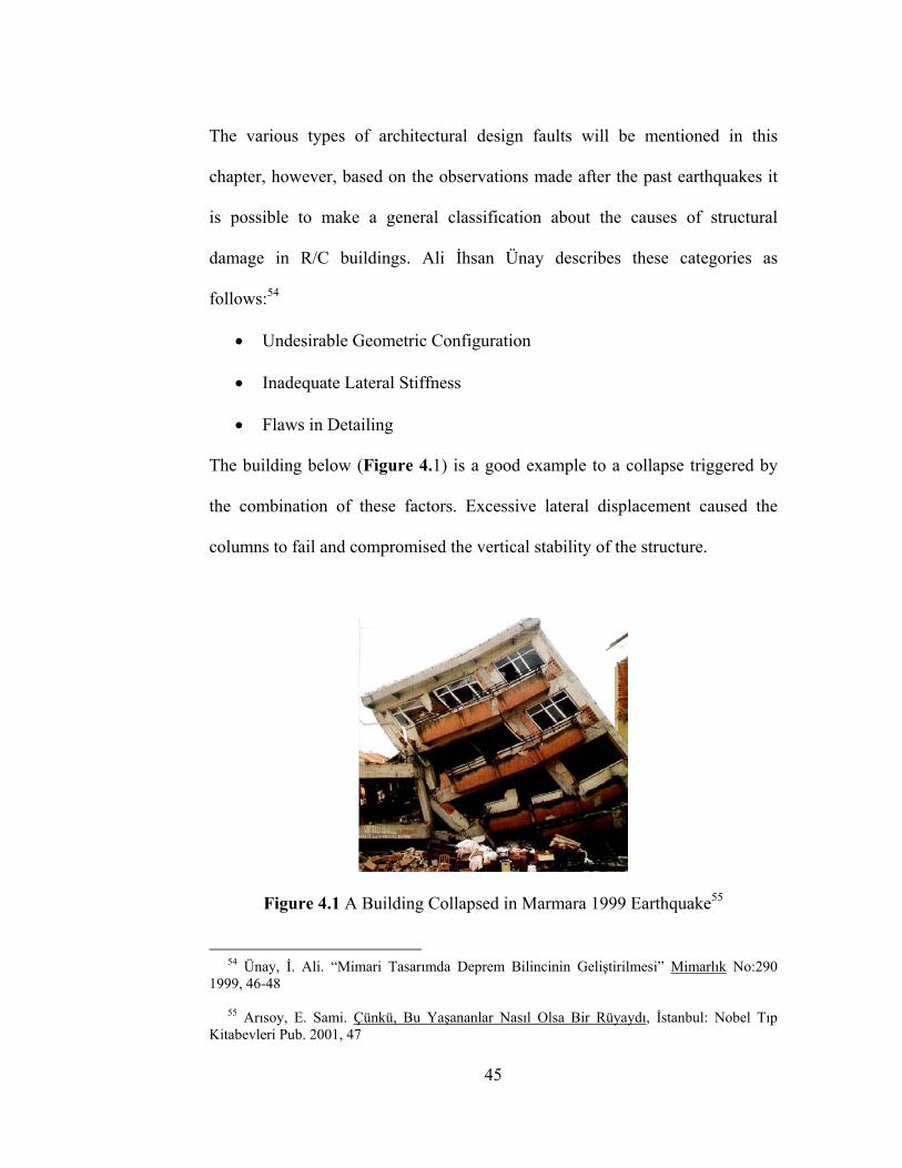
The various types of architectural design faults will be mentioned in this
chapter, however, based on the observations made after the past earthquakes it
is possible to make a general classification about the causes of structural
damage in R/C buildings. Ali İhsan Ünay describes these categories as
follows:54
• Undesirable Geometric Configuration
• Inadequate Lateral Stiffness
• Flaws in Detailing
The building below (Figure 4.1) is a good example to a collapse triggered by
the combination of these factors. Excessive lateral displacement caused the
columns to fail and compromised the vertical stability of the structure.
Figure 4.1 A Building Collapsed in Marmara 1999 Earthquake55
54 Ünay, İ. Ali. “Mimari Tasarımda Deprem Bilincinin Geliştirilmesi” Mimarlık No:290 1999, 46-48 55 Arısoy, E. Sami. Çünkü, Bu Yaşananlar Nasıl Olsa Bir Rüyaydı, İstanbul: Nobel Tıp Kitabevleri Pub. 2001, 47
45
There is a general misunderstanding between architects and students of
architecture that the seismic design rules and specifications set a limit to the
creative freedom of a designer. This idea is further enhanced by the indifference
of the system of architectural education to the issue and the current Turkish
Earthquake Code, which is apparently written for the understanding of civil
engineers.
The seismic design fault definitions in this chapter are made for the architects
and especially for the students of architecture. It is the author’s belief that an
adequate verbal definition supported by the apt graphic material will be more
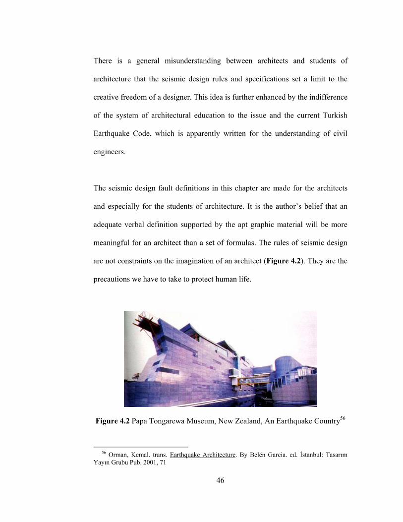
meaningful for an architect than a set of formulas. The rules of seismic design
are not constraints on the imagination of an architect (Figure 4.2). They are the
precautions we have to take to protect human life.
Figure 4.2 Papa Tongarewa Museum, New Zealand, An Earthquake Country56
56 Orman, Kemal. trans. Earthquake Architecture. By Belén Garcia. ed. İstanbul: Tasarım Yayın Grubu Pub. 2001, 71
46
4.2 Seismic Design Faults In Plan
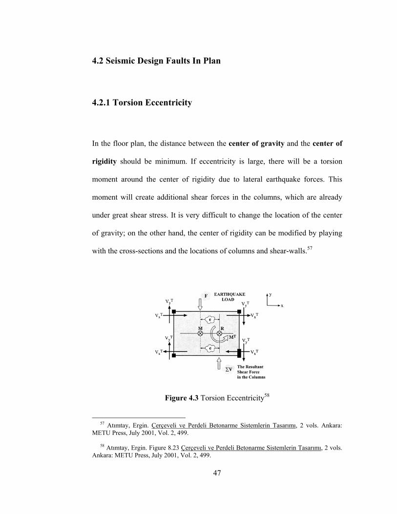
4.2.1 Torsion Eccentricity
In the floor plan, the distance between the center of gravity and the center of
rigidity should be minimum. If eccentricity is large, there will be a torsion
moment around the center of rigidity due to lateral earthquake forces. This
moment will create additional shear forces in the columns, which are already
under great shear stress. It is very difficult to change the location of the center
of gravity; on the other hand, the center of rigidity can be modified by playing
with the cross-sections and the locations of columns and shear-walls.57
Figure 4.3 Torsion Eccentricity58
57 Atımtay, Ergin. Çerçeveli ve Perdeli Betonarme Sistemlerin Tasarımı, 2 vols. Ankara: METU Press, July 2001, Vol. 2, 499. 58 Atımtay, Ergin. Figure 8.23 Çerçeveli ve Perdeli Betonarme Sistemlerin Tasarımı, 2 vols. Ankara: METU Press, July 2001, Vol. 2, 499.
47
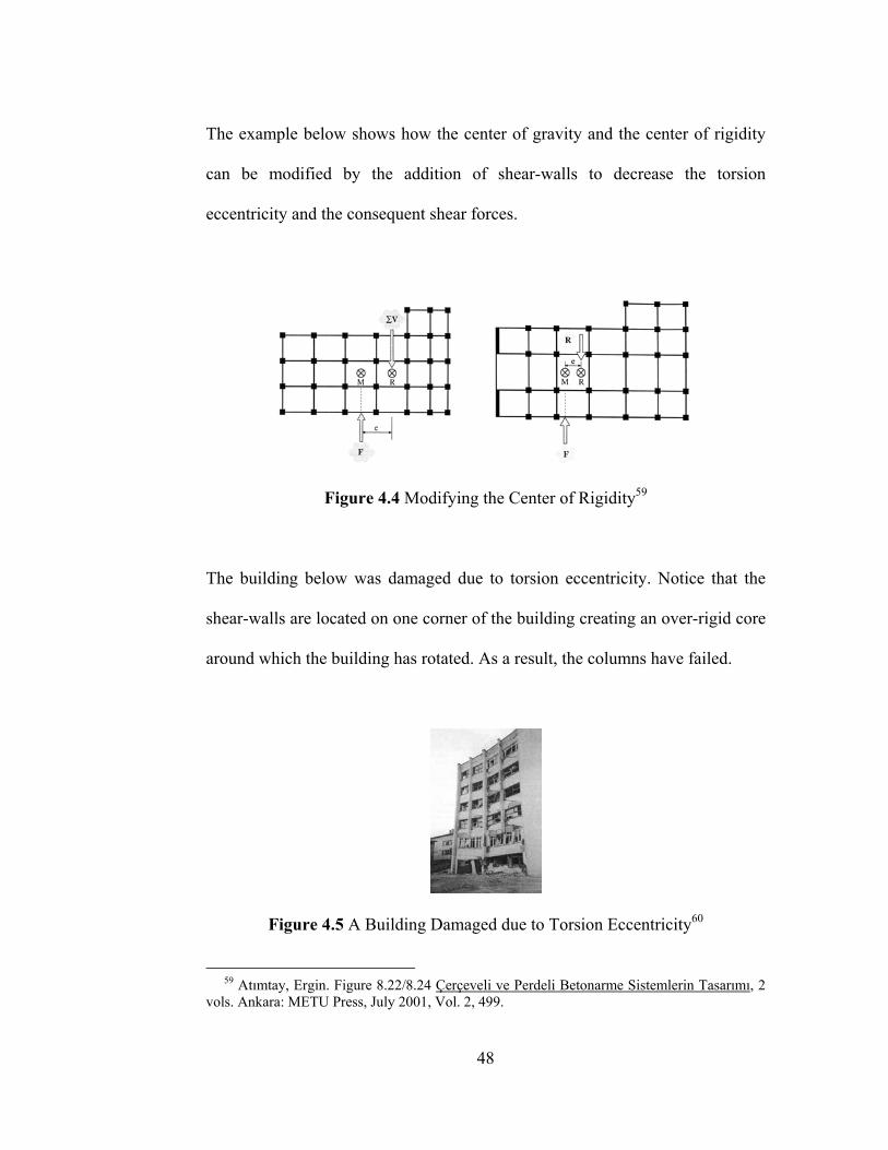
The example below shows how the center of gravity and the center of rigidity
can be modified by the addition of shear-walls to decrease the torsion
eccentricity and the consequent shear forces.
Figure 4.4 Modifying the Center of Rigidity59
The building below was damaged due to torsion eccentricity. Notice that the
shear-walls are located on one corner of the building creating an over-rigid core
around which the building has rotated. As a result, the columns have failed.
Figure 4.5 A Building Damaged due to Torsion Eccentricity60
59 Atımtay, Ergin. Figure 8.22/8.24 Çerçeveli ve Perdeli Betonarme Sistemlerin Tasarımı, 2 vols. Ankara: METU Press, July 2001, Vol. 2, 499.
48

The Turkish Earthquake Code mentions the torsion eccentricity as follows:
A1. Torsion Irregularity The case in which the Torsion Irregularity Factor, which is defined as the ratio of the maximum storey drift to the average storey drift at any storey exceeds 1.2 in any one of the two perpendicular earthquake directions. [ η ∆i = (∆i)max / (∆i)average > 1.2]
For any earthquake direction, if the rigidity of a building isn’t symmetrically
distributed, the less rigid portion of the structure will make a greater
displacement than the more rigid portion. If the ratio of the maximum
displacement to the average displacement at any floor is more than 1.2 than
there is a torsion irregularity in the building.
Assuming that the slab acts as a rigid diaphragm in the floor plane
(∆i)average = ½ [(∆i)max + (∆i)min]
Figure 4.6 Torsion Eccentricity in Turkish Earthquake Code61
60 Tuna, Mehmet Emin, Figure 8.8 Depreme Dayanıklı Yapı Tasarımı. Ankara: Tuna Eğitim ve Kültür Vakfı Pub. November 2000, 234. 61 Turkish Earthquake Code: Figure 6.1 Afet Bölgelerinde Yapılacak Yapılar Hakkında Yönetmelik. Ankara: 1998, 9.
49
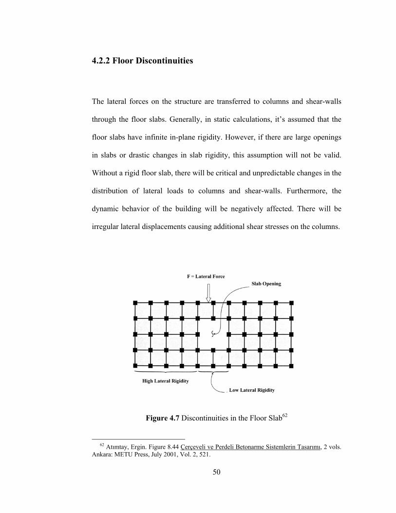
4.2.2 Floor Discontinuities
The lateral forces on the structure are transferred to columns and shear-walls
through the floor slabs. Generally, in static calculations, it’s assumed that the
floor slabs have infinite in-plane rigidity. However, if there are large openings
in slabs or drastic changes in slab rigidity, this assumption will not be valid.
Without a rigid floor slab, there will be critical and unpredictable changes in the
distribution of lateral loads to columns and shear-walls. Furthermore, the
dynamic behavior of the building will be negatively affected. There will be
irregular lateral displacements causing additional shear stresses on the columns.
Figure 4.7 Discontinuities in the Floor Slab62
62 Atımtay, Ergin. Figure 8.44 Çerçeveli ve Perdeli Betonarme Sistemlerin Tasarımı, 2 vols. Ankara: METU Press, July 2001, Vol. 2, 521.
50
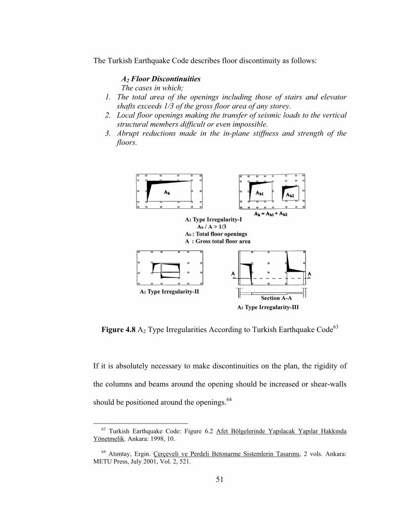
The Turkish Earthquake Code describes floor discontinuity as follows:
A2 Floor Discontinuities The cases in which;
1. The total area of the openings including those of stairs and elevator shafts exceeds 1/3 of the gross floor area of any storey.
2. Local floor openings making the transfer of seismic loads to the vertical structural members difficult or even impossible.
3. Abrupt reductions made in the in-plane stiffness and strength of the floors.
Figure 4.8 A2 Type Irregularities According to Turkish Earthquake Code63
If it is absolutely necessary to make discontinuities on the plan, the rigidity of
the columns and beams around the opening should be increased or shear-walls
should be positioned around the openings.64
63 Turkish Earthquake Code: Figure 6.2 Afet Bölgelerinde Yapılacak Yapılar Hakkında Yönetmelik. Ankara: 1998, 10. 64 Atımtay, Ergin. Çerçeveli ve Perdeli Betonarme Sistemlerin Tasarımı, 2 vols. Ankara: METU Press, July 2001, Vol. 2, 521.
51
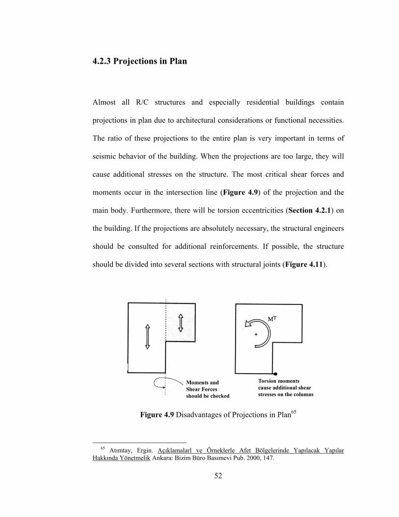
4.2.3 Projections in Plan
Almost all R/C structures and especially residential buildings contain
projections in plan due to architectural considerations or functional necessities.
The ratio of these projections to the entire plan is very important in terms of
seismic behavior of the building. When the projections are too large, they will
cause additional stresses on the structure. The most critical shear forces and
moments occur in the intersection line (Figure 4.9) of the projection and the
main body. Furthermore, there will be torsion eccentricities (Section 4.2.1) on
the building. If the projections are absolutely necessary, the structural engineers
should be consulted for additional reinforcements. If possible, the structure
should be divided into several sections with structural joints (Figure 4.11).
Figure 4.9 Disadvantages of Projections in Plan65
65 Atımtay, Ergin. Açıklamalarl ve Örneklerle Afet Bölgelerinde Yapılacak Yapılar Hakkında Yönetmelik Ankara: Bizim Büro Basımevi Pub. 2000, 147.
52
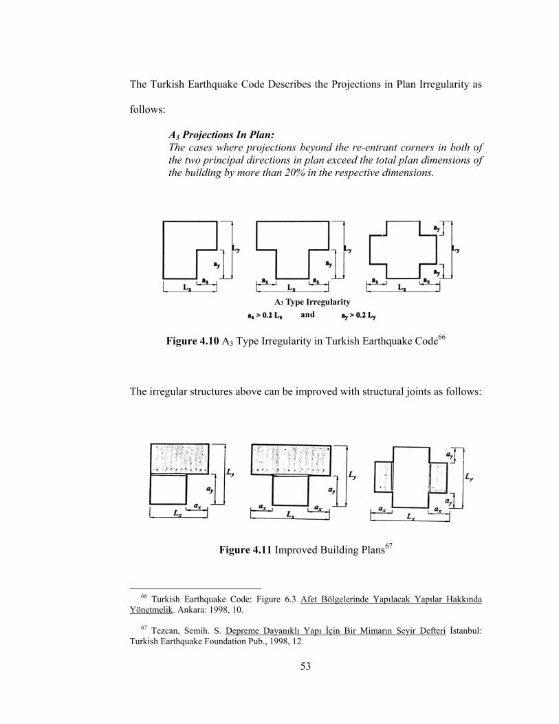
The Turkish Earthquake Code Describes the Projections in Plan Irregularity as
follows:
A3 Projections In Plan: The cases where projections beyond the re-entrant corners in both of the two principal directions in plan exceed the total plan dimensions of the building by more than 20% in the respective dimensions.
Figure 4.10 A3 Type Irregularity in Turkish Earthquake Code66
The irregular structures above can be improved with structural joints as follows:
Figure 4.11 Improved Building Plans67
66 Turkish Earthquake Code: Figure 6.3 Afet Bölgelerinde Yapılacak Yapılar Hakkında Yönetmelik. Ankara: 1998, 10. 67 Tezcan, Semih. S. Depreme Dayanıklı Yapı İçin Bir Mimarın Seyir Defteri İstanbul: Turkish Earthquake Foundation Pub., 1998, 12.
53
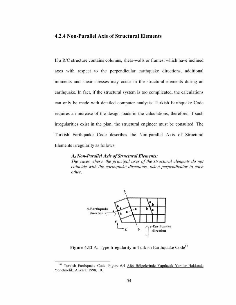
4.2.4 Non-Parallel Axis of Structural Elements
If a R/C structure contains columns, shear-walls or frames, which have inclined
axes with respect to the perpendicular earthquake directions, additional
moments and shear stresses may occur in the structural elements during an
earthquake. In fact, if the structural system is too complicated, the calculations
can only be made with detailed computer analysis. Turkish Earthquake Code
requires an increase of the design loads in the calculations, therefore; if such
irregularities exist in the plan, the structural engineer must be consulted. The
Turkish Earthquake Code describes the Non-parallel Axis of Structural
Elements Irregularity as follows:
A4 Non-Parallel Axis of Structural Elements: The cases where, the principal axes of the structural elements do not coincide with the earthquake directions, taken perpendicular to each other.
Figure 4.12 A4 Type Irregularity in Turkish Earthquake Code68
68 Turkish Earthquake Code: Figure 6.4 Afet Bölgelerinde Yapılacak Yapılar Hakkında Yönetmelik. Ankara: 1998, 10.
54
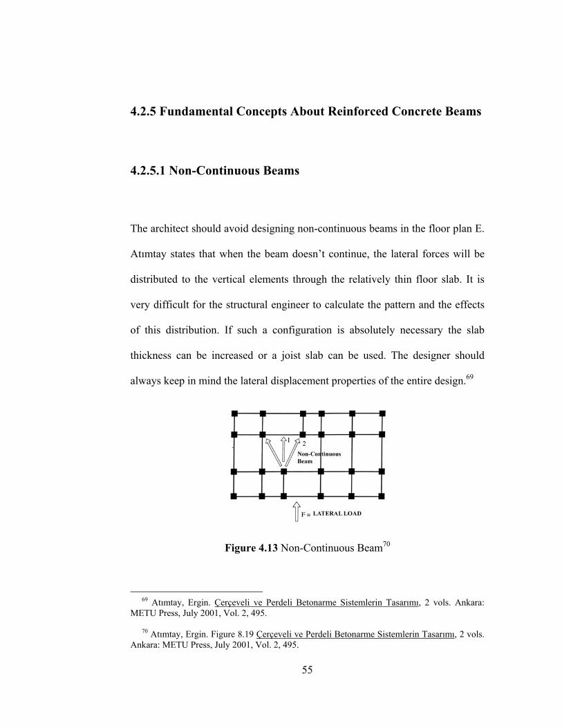
4.2.5 Fundamental Concepts About Reinforced Concrete Beams
4.2.5.1 Non-Continuous Beams
The architect should avoid designing non-continuous beams in the floor plan E.
Atımtay states that when the beam doesn’t continue, the lateral forces will be
distributed to the vertical elements through the relatively thin floor slab. It is
very difficult for the structural engineer to calculate the pattern and the effects
of this distribution. If such a configuration is absolutely necessary the slab
thickness can be increased or a joist slab can be used. The designer should
always keep in mind the lateral displacement properties of the entire design.69
Figure 4.13 Non-Continuous Beam70
69 Atımtay, Ergin. Çerçeveli ve Perdeli Betonarme Sistemlerin Tasarımı, 2 vols. Ankara: METU Press, July 2001, Vol. 2, 495. 70 Atımtay, Ergin. Figure 8.19 Çerçeveli ve Perdeli Betonarme Sistemlerin Tasarımı, 2 vols. Ankara: METU Press, July 2001, Vol. 2, 495.
55

4.2.5.2 Irregular Spans and Beam Cross-Sections
In a design jury, the most fervent debates between the architects and the
engineers are made because the engineers recommend structures having regular
spans, “called 6m by 6m frame rule” by M.E.T.U students. Architects however,
find such a limitation to their creative freedom revolting. Both sides have
reason in their own terms. Nevertheless, there is a simple explanation for this
advice of the engineers. Firstly, with irregular spans the lateral rigidity of the
entire system will be very unpredictable in an earthquake situation. Besides
this, if there are altering beam cross-sections it’s very difficult to estimate the
critical stresses in the structural elements under lateral loads. Furthermore, the
formwork cost will be very expensive. The reinforcement details will be very
complicated and difficult to produce especially in Turkey. That’s why standard
spans and uniform cross-sections are recommended for R/C structures.
Figure 4.14 Joint Between Beams with Different Cross-Sections71
71 Atımtay, Ergin. Figure 8.20/8.21 Çerçeveli ve Perdeli Betonarme Sistemlerin Tasarımı, 2 vols. Ankara: METU Press, July 2001, Vol. 2, 495.
56
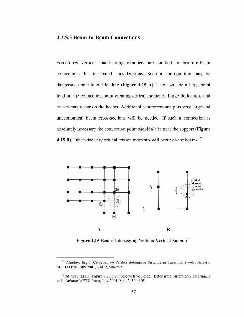
4.2.5.3 Beam-to-Beam Connections
Sometimes vertical load-bearing members are omitted in beam-to-beam
connections due to spatial considerations. Such a configuration may be
dangerous under lateral loading (Figure 4.15 A). There will be a large point
load on the connection point creating critical moments. Large deflections and
cracks may occur on the beams. Additional reinforcements plus very large and
uneconomical beam cross-sections will be needed. If such a connection is
absolutely necessary the connection point shouldn’t be near the support (Figure
4.15 B). Otherwise very critical torsion moments will occur on the beams. 72
A B
Figure 4.15 Beams Intersecting Without Vertical Support73
72 Atımtay, Ergin. Çerçeveli ve Perdeli Betonarme Sistemlerin Tasarımı, 2 vols. Ankara: METU Press, July 2001, Vol. 2, 504-505. 73 Atımtay, Ergin. Figure 8.28/8.29 Çerçeveli ve Perdeli Betonarme Sistemlerin Tasarımı, 2 vols. Ankara: METU Press, July 2001, Vol. 2, 504-505.
57
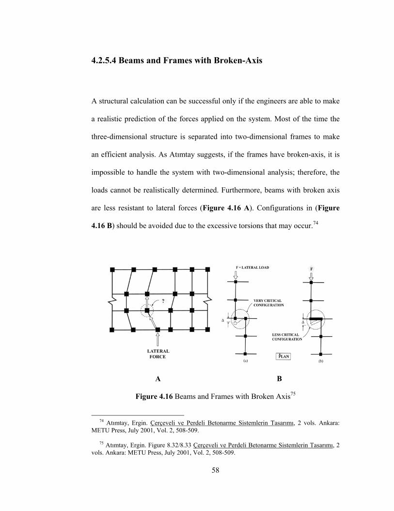
4.2.5.4 Beams and Frames with Broken-Axis
A structural calculation can be successful only if the engineers are able to make
a realistic prediction of the forces applied on the system. Most of the time the
three-dimensional structure is separated into two-dimensional frames to make
an efficient analysis. As Atımtay suggests, if the frames have broken-axis, it is
impossible to handle the system with two-dimensional analysis; therefore, the
loads cannot be realistically determined. Furthermore, beams with broken axis
are less resistant to lateral forces (Figure 4.16 A). Configurations in (Figure
4.16 B) should be avoided due to the excessive torsions that may occur.74
A B
Figure 4.16 Beams and Frames with Broken Axis75
74 Atımtay, Ergin. Çerçeveli ve Perdeli Betonarme Sistemlerin Tasarımı, 2 vols. Ankara: METU Press, July 2001, Vol. 2, 508-509. 75 Atımtay, Ergin. Figure 8.32/8.33 Çerçeveli ve Perdeli Betonarme Sistemlerin Tasarımı, 2 vols. Ankara: METU Press, July 2001, Vol. 2, 508-509.
58
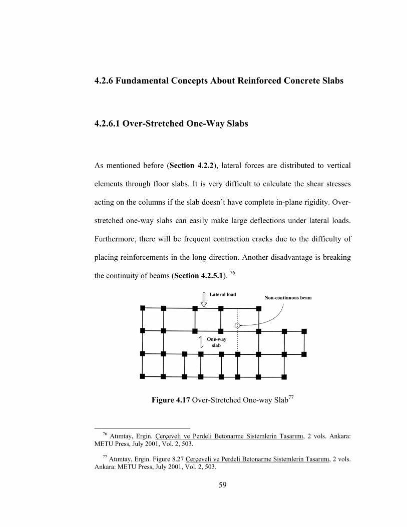
4.2.6 Fundamental Concepts About Reinforced Concrete Slabs
4.2.6.1 Over-Stretched One-Way Slabs
As mentioned before (Section 4.2.2), lateral forces are distributed to vertical
elements through floor slabs. It is very difficult to calculate the shear stresses
acting on the columns if the slab doesn’t have complete in-plane rigidity. Over-
stretched one-way slabs can easily make large deflections under lateral loads.
Furthermore, there will be frequent contraction cracks due to the difficulty of
placing reinforcements in the long direction. Another disadvantage is breaking
the continuity of beams (Section 4.2.5.1). 76
Figure 4.17 Over-Stretched One-way Slab77
76 Atımtay, Ergin. Çerçeveli ve Perdeli Betonarme Sistemlerin Tasarımı, 2 vols. Ankara: METU Press, July 2001, Vol. 2, 503. 77 Atımtay, Ergin. Figure 8.27 Çerçeveli ve Perdeli Betonarme Sistemlerin Tasarımı, 2 vols. Ankara: METU Press, July 2001, Vol. 2, 503.
59

4.2.6.2 Rules About Joist-Slabs
Joist-slabs and especially block-joist slabs are very commonly used in
residential buildings in Turkey due to aesthetic reasons and the ease of
formwork. In block-joist slabs the side-beams are made shallow to match with
the dimensions of the joists for easy formwork. According to Karaesmen, this
makes the beams vulnerable to deflections due to lateral forces. The large
lateral displacements in the slab may damage the beams. More critically, the
bond between the floor blocks and the joists may be destroyed. The floor blocks
will fall down causing great material damage and possibly human casualties. 78
Figure 4.18 Deflection Damage near Shallow Beams in a Block-Joist Slab79
78 Karaesmen, Erhan. & Buğdaycıoğlu, B. Elif. Yapısal Hasar Türleri ve Ek Hasarı Arttırıcı Unsurlar N.p 79 Demirtaş, Ramazan. ed., 17 Ağustos 1999 İzmit Körfezi Depremi Raporu, Ankara: January 2000, 245.
60
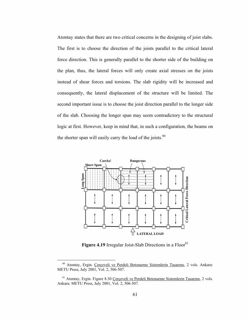
Atımtay states that there are two critical concerns in the designing of joist slabs.
The first is to choose the direction of the joists parallel to the critical lateral
force direction. This is generally parallel to the shorter side of the building on
the plan, thus, the lateral forces will only create axial stresses on the joists
instead of shear forces and torsions. The slab rigidity will be increased and
consequently, the lateral displacement of the structure will be limited. The
second important issue is to choose the joist direction parallel to the longer side
of the slab. Choosing the longer span may seem contradictory to the structural
logic at first. However, keep in mind that, in such a configuration, the beams on
the shorter span will easily carry the load of the joists.80
Figure 4.19 Irregular Joist-Slab Directions in a Floor81
80 Atımtay, Ergin. Çerçeveli ve Perdeli Betonarme Sistemlerin Tasarımı, 2 vols. Ankara: METU Press, July 2001, Vol. 2, 506-507. 81 Atımtay, Ergin. Figure 8.30 Çerçeveli ve Perdeli Betonarme Sistemlerin Tasarımı, 2 vols. Ankara: METU Press, July 2001, Vol. 2, 506-507.
61
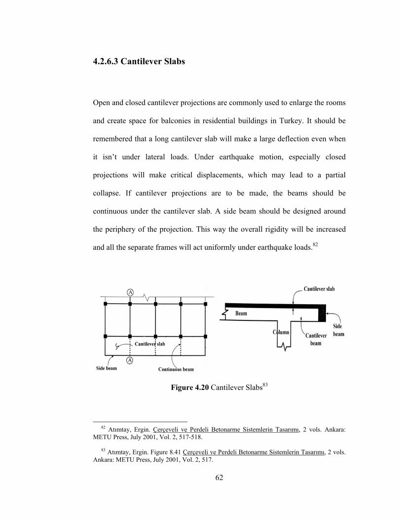
4.2.6.3 Cantilever Slabs
Open and closed cantilever projections are commonly used to enlarge the rooms
and create space for balconies in residential buildings in Turkey. It should be
remembered that a long cantilever slab will make a large deflection even when
it isn’t under lateral loads. Under earthquake motion, especially closed
projections will make critical displacements, which may lead to a partial
collapse. If cantilever projections are to be made, the beams should be
continuous under the cantilever slab. A side beam should be designed around
the periphery of the projection. This way the overall rigidity will be increased
and all the separate frames will act uniformly under earthquake loads.82
Figure 4.20 Cantilever Slabs83
82 Atımtay, Ergin. Çerçeveli ve Perdeli Betonarme Sistemlerin Tasarımı, 2 vols. Ankara: METU Press, July 2001, Vol. 2, 517-518. 83 Atımtay, Ergin. Figure 8.41 Çerçeveli ve Perdeli Betonarme Sistemlerin Tasarımı, 2 vols. Ankara: METU Press, July 2001, Vol. 2, 517.
62
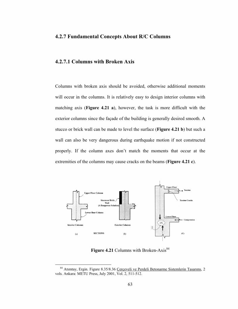
4.2.7 Fundamental Concepts About R/C Columns
4.2.7.1 Columns with Broken Axis
Columns with broken axis should be avoided, otherwise additional moments
will occur in the columns. It is relatively easy to design interior columns with
matching axis (Figure 4.21 a), however, the task is more difficult with the
exterior columns since the façade of the building is generally desired smooth. A
stucco or brick wall can be made to level the surface (Figure 4.21 b) but such a
wall can also be very dangerous during earthquake motion if not constructed
properly. If the column axes don’t match the moments that occur at the
extremities of the columns may cause cracks on the beams (Figure 4.21 c).
Figure 4.21 Columns with Broken-Axis84
84 Atımtay, Ergin. Figure 8.35/8.36 Çerçeveli ve Perdeli Betonarme Sistemlerin Tasarımı, 2 vols. Ankara: METU Press, July 2001, Vol. 2, 511-512.
63
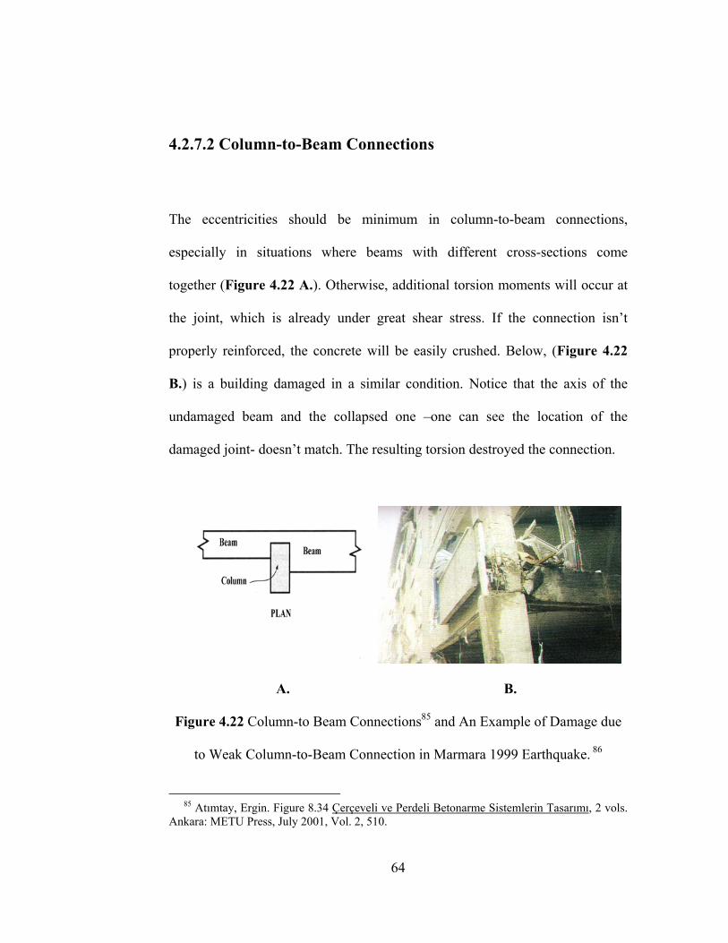
4.2.7.2 Column-to-Beam Connections
The eccentricities should be minimum in column-to-beam connections,
especially in situations where beams with different cross-sections come
together (Figure 4.22 A.). Otherwise, additional torsion moments will occur at
the joint, which is already under great shear stress. If the connection isn’t
properly reinforced, the concrete will be easily crushed. Below, (Figure 4.22
B.) is a building damaged in a similar condition. Notice that the axis of the
undamaged beam and the collapsed one –one can see the location of the
damaged joint- doesn’t match. The resulting torsion destroyed the connection.
A. B.
Figure 4.22 Column-to Beam Connections85 and An Example of Damage due
to Weak Column-to-Beam Connection in Marmara 1999 Earthquake. 86
85 Atımtay, Ergin. Figure 8.34 Çerçeveli ve Perdeli Betonarme Sistemlerin Tasarımı, 2 vols. Ankara: METU Press, July 2001, Vol. 2, 510.
64
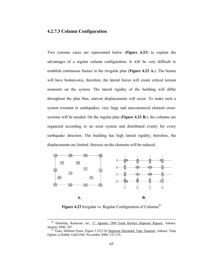
4.2.7.3 Column Configuration
Two extreme cases are represented below (Figure 4.23) to explain the
advantages of a regular column configuration. It will be very difficult to
establish continuous frames in the irregular plan (Figure 4.23 A.). The beams
will have broken-axis, therefore, the lateral forces will create critical torsion
moments on the system. The lateral rigidity of the building will differ
throughout the plan thus, uneven displacements will occur. To make such a
system resistant to earthquakes, very large and uneconomical element cross-
sections will be needed. On the regular plan (Figure 4.23 B.), the columns are
organized according to an axial system and distributed evenly for every
earthquake direction. The building has high lateral rigidity; therefore, the
displacements are limited. Stresses on the elements will be reduced.
A. B.
Figure 4.23 Irregular vs. Regular Configuration of Columns87
86 Demirtaş, Ramazan. ed., 17 Ağustos 1999 İzmit Körfezi Depremi Raporu, Ankara: January 2000, 247. 87 Tuna, Mehmet Emin, Figure 5.22/5.26 Depreme Dayanıklı Yapı Tasarımı. Ankara: Tuna Eğitim ve Kültür Vakfı Pub. November 2000, 133-135.
65

4.2.8 Fundamental Concepts About R/C Shear-Walls
4.2.8.1 Location of Shear-Walls
Shear-walls are the most effective method of making earthquake resistant
buildings. They increase the lateral rigidity of the structure and reduce
excessive displacements. The location of the shear-walls should be chosen
carefully keeping in mind that the centers of gravity and rigidity are supposed
to be as near as possible. If the shear-walls are concentrated on one side of the
building (Figure 4.24 A.), there will be excessive torsion eccentricities
(Section 4.2.1) and uneven displacements on the structure. Shear-walls should
be located symmetrically and near the center of the building (Figure 4.24 B.).
A. B.
Figure 4.24 Location of Shear-walls.88
88 Gönençen, Kaya. Figure 2/Figure 3A Mimari Proje Tasarımında Depreme Karşı Yapı Davranışının Düzenlenmesi, Ankara: Teknik Yayınevi Pub. 2000, 10-12.
66

4.2.8.2 Configuration of Shear-Walls
A shear-wall is a vertical load-bearing element whose longer side to shorter
side ratio is greater than seven. According to the Turkish Earthquake Code the
width of a shear-wall can be 20 cm minimum. Similar to the configuration of
columns (Section 4.2.7.3), it is better if the shear-walls are organized according
to an axial system. A symmetrical configuration is the most preferable one.
Shear-walls should be distributed evenly for every earthquake direction.
Remember that the critical lateral force direction is parallel to the shorter side
of the building. Shear-walls should be perpendicular to the building façades in
this direction. For architectural purposes, shear-walls can be hidden around
staircase and elevator shafts or placed on the façades of the building.
A. B.
Figure 4.25 Irregular vs. Regular Configuration of Shear-Walls89
89 Tuna, Mehmet Emin, Figure 5.33/5.34 Depreme Dayanıklı Yapı Tasarımı. Ankara: Tuna Eğitim ve Kültür Vakfı Pub. November 2000, 139-140.
67
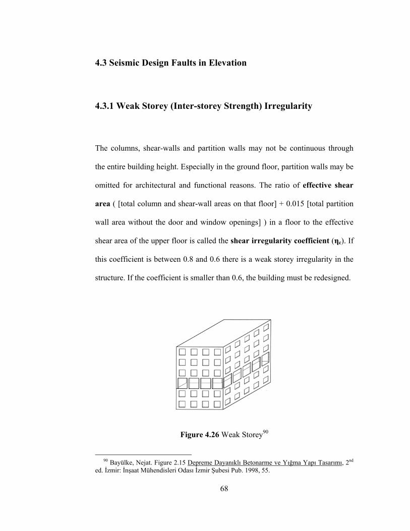
4.3 Seismic Design Faults in Elevation
4.3.1 Weak Storey (Inter-storey Strength) Irregularity
The columns, shear-walls and partition walls may not be continuous through
the entire building height. Especially in the ground floor, partition walls may be
omitted for architectural and functional reasons. The ratio of effective shear
area ( [total column and shear-wall areas on that floor] + 0.015 [total partition
wall area without the door and window openings] ) in a floor to the effective
shear area of the upper floor is called the shear irregularity coefficient (ηc). If
this coefficient is between 0.8 and 0.6 there is a weak storey irregularity in the
structure. If the coefficient is smaller than 0.6, the building must be redesigned.
Figure 4.26 Weak Storey90
90 Bayülke, Nejat. Figure 2.15 Depreme Dayanıklı Betonarme ve Yığma Yapı Tasarımı, 2nd ed. İzmir: İnşaat Mühendisleri Odası İzmir Şubesi Pub. 1998, 55.
68
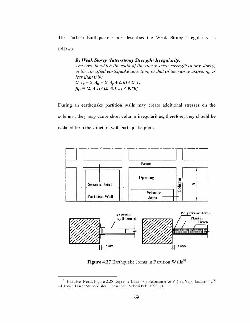
The Turkish Earthquake Code describes the Weak Storey Irregularity as
follows:
B1 Weak Storey (Inter-storey Strength) Irregularity: The case in which the ratio of the storey shear strength of any storey, in the specified earthquake direction, to that of the storey above, ηc, is less than 0.80. Σ Ae = Σ Aw + Σ Ag + 0.015 Σ Ak [ηc = (Σ Ae)I / (Σ Ae)I + 1 < 0.80]
During an earthquake partition walls may create additional stresses on the
columns, they may cause short-column irregularities, therefore, they should be
isolated from the structure with earthquake joints.
Figure 4.27 Earthquake Joints in Partition Walls91
91 Bayülke, Nejat. Figure 2.28 Depreme Dayanıklı Betonarme ve Yığma Yapı Tasarımı, 2nd ed. İzmir: İnşaat Mühendisleri Odası İzmir Şubesi Pub. 1998, 71.
69
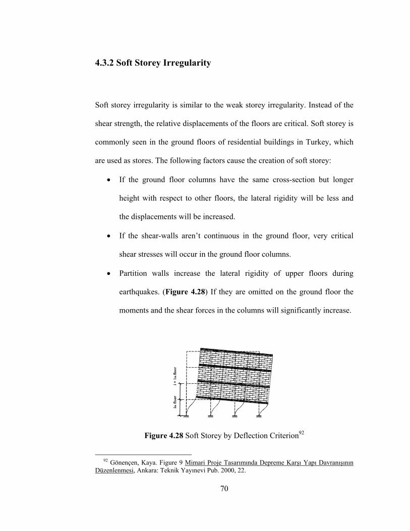
4.3.2 Soft Storey Irregularity
Soft storey irregularity is similar to the weak storey irregularity. Instead of the
shear strength, the relative displacements of the floors are critical. Soft storey is
commonly seen in the ground floors of residential buildings in Turkey, which
are used as stores. The following factors cause the creation of soft storey:
• If the ground floor columns have the same cross-section but longer
height with respect to other floors, the lateral rigidity will be less and
the displacements will be increased.
• If the shear-walls aren’t continuous in the ground floor, very critical
shear stresses will occur in the ground floor columns.
• Partition walls increase the lateral rigidity of upper floors during
earthquakes. (Figure 4.28) If they are omitted on the ground floor the
moments and the shear forces in the columns will significantly increase.
Figure 4.28 Soft Storey by Deflection Criterion92
92 Gönençen, Kaya. Figure 9 Mimari Proje Tasarımında Depreme Karşı Yapı Davranışının Düzenlenmesi, Ankara: Teknik Yayınevi Pub. 2000, 22.
70
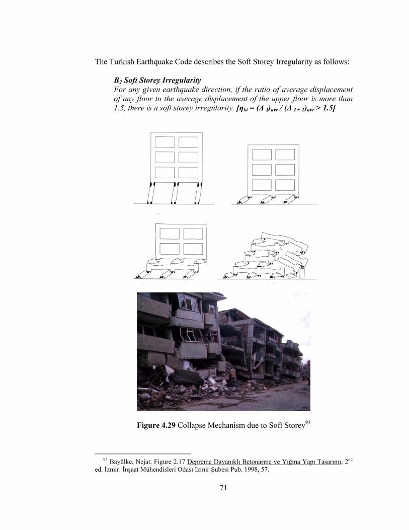
The Turkish Earthquake Code describes the Soft Storey Irregularity as follows:
B2 Soft Storey Irregularity For any given earthquake direction, if the ratio of average displacement of any floor to the average displacement of the upper floor is more than 1.5, there is a soft storey irregularity. [ηki = (∆ I)avr / (∆ I + 1)avr > 1.5]
Figure 4.29 Collapse Mechanism due to Soft Storey93
93 Bayülke, Nejat. Figure 2.17 Depreme Dayanıklı Betonarme ve Yığma Yapı Tasarımı, 2nd ed. İzmir: İnşaat Mühendisleri Odası İzmir Şubesi Pub. 1998, 57.
71

4.3.3 Discontinuity of Vertical Structural Elements
Architects may choose to omit the vertical structural elements in some cases
due to spatial, functional or aesthetical concerns. It is possible for a beam to
carry the load of a column, however this will require uneconomical cross-
sections. There will be excessive moments and shear stresses on the beams
during an earthquake. The Turkish Earthquake Code describes this irregularity
as follows:
B3 Discontinuity of Vertical Structural Elements: There is B3 type irregularity in the cases, where the vertical structural elements (columns or shear-walls) are removed in some stories and supported by beams underneath, or the shear-walls in the upper stories are supported by columns underneath.
Figure 4.30 Discontinuity of Vertical Members in Earthquake Code94
94 Turkish Earthquake Code: Figure 6.5 Afet Bölgelerinde Yapılacak Yapılar Hakkında Yönetmelik. Ankara: 1998, 11.
72
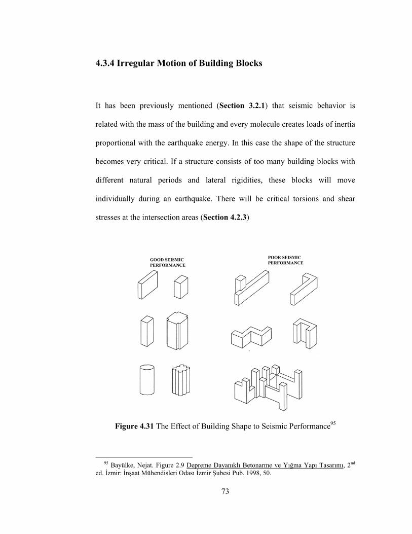
4.3.4 Irregular Motion of Building Blocks
It has been previously mentioned (Section 3.2.1) that seismic behavior is
related with the mass of the building and every molecule creates loads of inertia
proportional with the earthquake energy. In this case the shape of the structure
becomes very critical. If a structure consists of too many building blocks with
different natural periods and lateral rigidities, these blocks will move
individually during an earthquake. There will be critical torsions and shear
stresses at the intersection areas (Section 4.2.3)
Figure 4.31 The Effect of Building Shape to Seismic Performance95
95 Bayülke, Nejat. Figure 2.9 Depreme Dayanıklı Betonarme ve Yığma Yapı Tasarımı, 2nd ed. İzmir: İnşaat Mühendisleri Odası İzmir Şubesi Pub. 1998, 50.
73
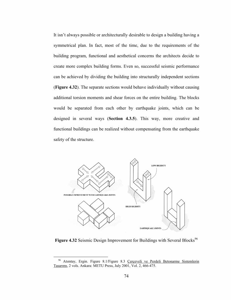
It isn’t always possible or architecturally desirable to design a building having a
symmetrical plan. In fact, most of the time, due to the requirements of the
building program, functional and aesthetical concerns the architects decide to
create more complex building forms. Even so, successful seismic performance
can be achieved by dividing the building into structurally independent sections
(Figure 4.32). The separate sections would behave individually without causing
additional torsion moments and shear forces on the entire building. The blocks
would be separated from each other by earthquake joints, which can be
designed in several ways (Section 4.3.5). This way, more creative and
functional buildings can be realized without compensating from the earthquake
safety of the structure.
Figure 4.32 Seismic Design Improvement for Buildings with Several Blocks96
96 Atımtay, Ergin. Figure 8.1/Figure 8.3 Çerçeveli ve Perdeli Betonarme Sistemlerin Tasarımı, 2 vols. Ankara: METU Press, July 2001, Vol. 2, 466-475.
74
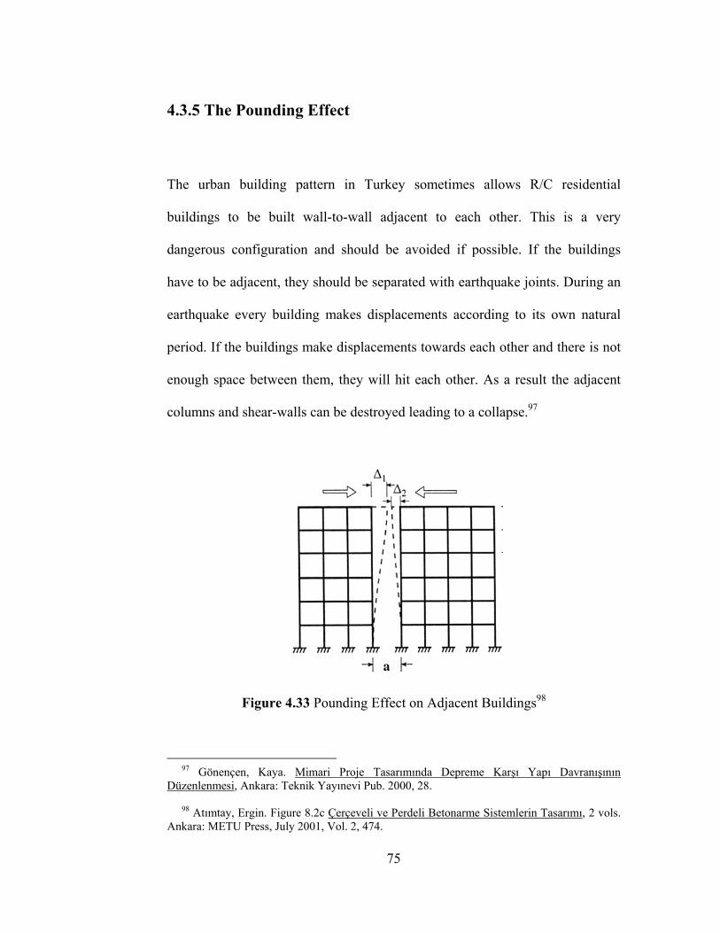
4.3.5 The Pounding Effect
The urban building pattern in Turkey sometimes allows R/C residential
buildings to be built wall-to-wall adjacent to each other. This is a very
dangerous configuration and should be avoided if possible. If the buildings
have to be adjacent, they should be separated with earthquake joints. During an
earthquake every building makes displacements according to its own natural
period. If the buildings make displacements towards each other and there is not
enough space between them, they will hit each other. As a result the adjacent
columns and shear-walls can be destroyed leading to a collapse.97
Figure 4.33 Pounding Effect on Adjacent Buildings98
97 Gönençen, Kaya. Mimari Proje Tasarımında Depreme Karşı Yapı Davranışının Düzenlenmesi, Ankara: Teknik Yayınevi Pub. 2000, 28. 98 Atımtay, Ergin. Figure 8.2c Çerçeveli ve Perdeli Betonarme Sistemlerin Tasarımı, 2 vols. Ankara: METU Press, July 2001, Vol. 2, 474.
75
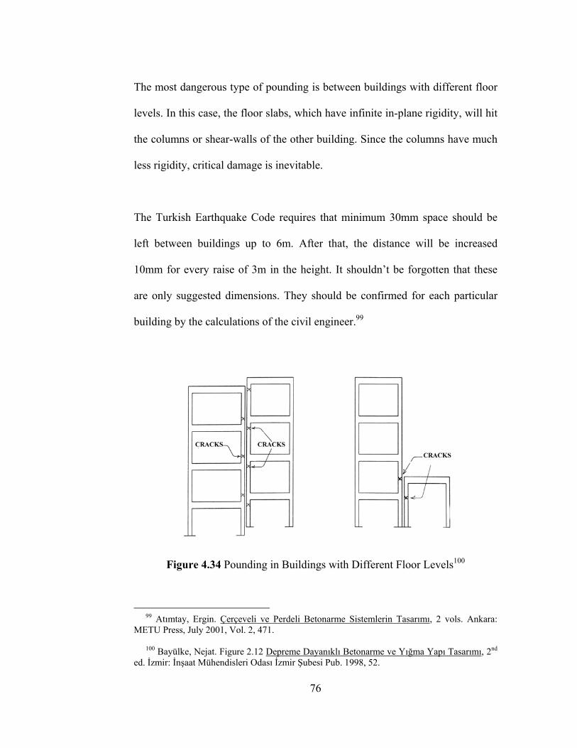
The most dangerous type of pounding is between buildings with different floor
levels. In this case, the floor slabs, which have infinite in-plane rigidity, will hit
the columns or shear-walls of the other building. Since the columns have much
less rigidity, critical damage is inevitable.
The Turkish Earthquake Code requires that minimum 30mm space should be
left between buildings up to 6m. After that, the distance will be increased
10mm for every raise of 3m in the height. It shouldn’t be forgotten that these
are only suggested dimensions. They should be confirmed for each particular
building by the calculations of the civil engineer.99
Figure 4.34 Pounding in Buildings with Different Floor Levels100
99 Atımtay, Ergin. Çerçeveli ve Perdeli Betonarme Sistemlerin Tasarımı, 2 vols. Ankara: METU Press, July 2001, Vol. 2, 471. 100 Bayülke, Nejat. Figure 2.12 Depreme Dayanıklı Betonarme ve Yığma Yapı Tasarımı, 2nd ed. İzmir: İnşaat Mühendisleri Odası İzmir Şubesi Pub. 1998, 52.
76
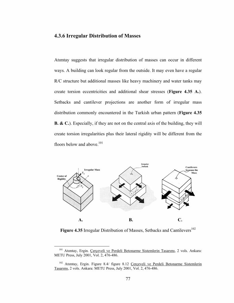
4.3.6 Irregular Distribution of Masses
Atımtay suggests that irregular distribution of masses can occur in different
ways. A building can look regular from the outside. It may even have a regular
R/C structure but additional masses like heavy machinery and water tanks may
create torsion eccentricities and additional shear stresses (Figure 4.35 A.).
Setbacks and cantilever projections are another form of irregular mass
distribution commonly encountered in the Turkish urban pattern (Figure 4.35
B. & C.). Especially, if they are not on the central axis of the building, they will
create torsion irregularities plus their lateral rigidity will be different from the
floors below and above.101
A. B. C.
Figure 4.35 Irregular Distribution of Masses, Setbacks and Cantilevers102
101 Atımtay, Ergin. Çerçeveli ve Perdeli Betonarme Sistemlerin Tasarımı, 2 vols. Ankara: METU Press, July 2001, Vol. 2, 476-486. 102 Atımtay, Ergin. Figure 8.4/ figure 8.12 Çerçeveli ve Perdeli Betonarme Sistemlerin Tasarımı, 2 vols. Ankara: METU Press, July 2001, Vol. 2, 476-486.
77
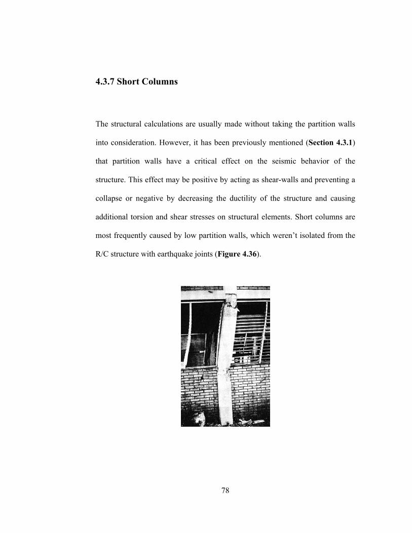
4.3.7 Short Columns
The structural calculations are usually made without taking the partition walls
into consideration. However, it has been previously mentioned (Section 4.3.1)
that partition walls have a critical effect on the seismic behavior of the
structure. This effect may be positive by acting as shear-walls and preventing a
collapse or negative by decreasing the ductility of the structure and causing
additional torsion and shear stresses on structural elements. Short columns are
most frequently caused by low partition walls, which weren’t isolated from the
R/C structure with earthquake joints (Figure 4.36).
78

Figure 4.36 Short Column Example, Nicaragua 1972 Earthquake103
The principal behind the short column formation is simple. According to
Gönençen, when the height of a column decreases, the lateral rigidity of the
element increases and the more rigid a column is, the more lateral force it
attracts on itself. For example, if the height of a column is reduced to half, there
will be two times more bending moment on that element. Short column can
occur at every location where the height of a column is decreased with respect
to other storeys. Low mechanical floors, irregular beam depths in a frame, strip
windows or foundations on inclined topography may cause short columns.104
Figure 4.37 Types of Short Column Formations105
103 Tezcan, Semih. S. Figure 8.3 Depreme Dayanıklı Yapı İçin Bir Mimarın Seyir Defteri İstanbul: Turkish Earthquake Foundation Pub., 1998, 38. 104 Gönençen, Kaya. Mimari Proje Tasarımında Depreme Karşı Yapı Davranışının Düzenlenmesi, Ankara: Teknik Yayınevi Pub. 2000, 35. 105 Gönençen, Kaya. Figure 15 Mimari Proje Tasarımında Depreme Karşı Yapı Davranışının Düzenlenmesi, Ankara: Teknik Yayınevi Pub. 2000, 36.
79

4.3.8 Strong Beam-Weak Column Formation
In case of a strong earthquake, the design priority for a R/C structure is to
prevent a total or partial collapse in order to save human life. To achieve this,
the structure must be able to absorb the maximum energy by ductile
deformations in column-beam connections, while the lateral stability of the
building is preserved.
If the beams of a building are more rigid than the columns (Figure 4.38 A.),
ductile deformations will occur at the top and bottom ends of the columns.
Excessive displacements will cause additional moments and the columns will
easily loose their lateral stability. Since the greatest earthquake forces occur at
the ground floor, these columns will collapse first, probably causing the
destruction of the entire building.
If the columns are more rigid than the beams (Figure 4.38 B.), ductile
deformations will occur at the ends of the beams. R/C beams can absorb a lot of
energy by ductile deformations without an important loss in the load carrying
capacity. In this system, all the beam-column connections in the building have
to fail before the collapse of the ground floor columns. Architects should know
that strong Column-Weak Beam design is not only advisable but also
obligatory according to new Turkish Earthquake Code.
80
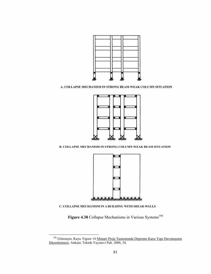
Figure 4.38 Collapse Mechanisms in Various Systems106
106 Gönençen, Kaya. Figure 14 Mimari Proje Tasarımında Depreme Karşı Yapı Davranışının Düzenlenmesi, Ankara: Teknik Yayınevi Pub. 2000, 34.
81
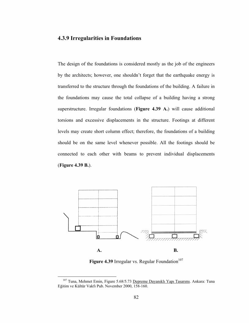
4.3.9 Irregularities in Foundations
The design of the foundations is considered mostly as the job of the engineers
by the architects; however, one shouldn’t forget that the earthquake energy is
transferred to the structure through the foundations of the building. A failure in
the foundations may cause the total collapse of a building having a strong
superstructure. Irregular foundations (Figure 4.39 A.) will cause additional
torsions and excessive displacements in the structure. Footings at different
levels may create short column effect; therefore, the foundations of a building
should be on the same level whenever possible. All the footings should be
connected to each other with beams to prevent individual displacements
(Figure 4.39 B.).
A. B.
Figure 4.39 Irregular vs. Regular Foundation107
107 Tuna, Mehmet Emin, Figure 5.68/5.73 Depreme Dayanıklı Yapı Tasarımı. Ankara: Tuna Eğitim ve Kültür Vakfı Pub. November 2000, 158-160.
82
CHAPTER V
THE EFFECT OF COMMONLY ENCOUNTERED SEISMIC
DESIGN FAULTS ON THE BUILDING STRUCTURE: A
SAMPLE STUDY CONDUCTED WITH COMPUTER
GENERATED STRUCTURAL MODELS
5.1 The Objective of the Study
It has been previously mentioned that one of the aims of this thesis is to create a
basic awareness of seismic behavior in architecture students. It is very
important for learners to see that the theoretical knowledge they receive is
applicable to real life conditions. Since it is very difficult, too costly and
impractical to simulate the seismic behavior of an entire building in a
laboratory, computer generated structural models are used in this chapter to
demonstrate the effect of the most commonly encountered seismic design faults
on the building structure.
83
5.2 The Scope and The Procedure
This study is conducted on six types of building models. The first two of these
models are based on actual buildings that were located in İzmit, Bekirpaşa
District. Both of these buildings have collapsed in Marmara 1999 Earthquake.
Due to the lack of detailed engineering reports on the reasons of collapse, it is
impossible to say that the buildings have collapsed due to the seismic design
faults mentioned in this chapter; however, it is a strong possibility that these
faults have played an important role in the failure of these structures. The
remaining four models are derived from architectural configurations that are
likely to occur in the real life. The buildings, the structural and architectural
elements are dimensioned similar to the R/C residential buildings that exist in
Turkish urban pattern.
The scope of this study is limited with the structural knowledge expected from
an architect. That means: this study doesn’t make a detailed structural analysis
of the buildings. There isn’t any discussion about the properties of the structural
materials, the amount of reinforcement or the load carrying capacity of
individual structural elements. This study simply shows that, if a building
contains one or more of the seismic design faults mentioned before, there will
be a significant increase in the stresses and moments that the building has to
resist during an earthquake.
84
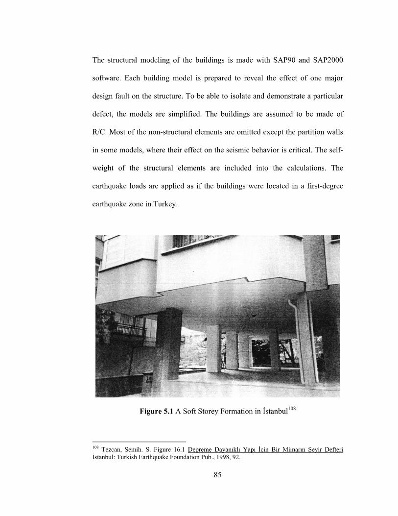
The structural modeling of the buildings is made with SAP90 and SAP2000
software. Each building model is prepared to reveal the effect of one major
design fault on the structure. To be able to isolate and demonstrate a particular
defect, the models are simplified. The buildings are assumed to be made of
R/C. Most of the non-structural elements are omitted except the partition walls
in some models, where their effect on the seismic behavior is critical. The self-
weight of the structural elements are included into the calculations. The
earthquake loads are applied as if the buildings were located in a first-degree
earthquake zone in Turkey.
Figure 5.1 A Soft Storey Formation in İstanbul108
108 Tezcan, Semih. S. Figure 16.1 Depreme Dayanıklı Yapı İçin Bir Mimarın Seyir Defteri İstanbul: Turkish Earthquake Foundation Pub., 1998, 92.
85
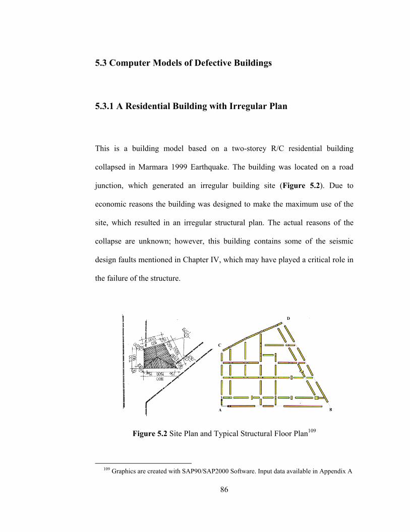
5.3 Computer Models of Defective Buildings
5.3.1 A Residential Building with Irregular Plan
This is a building model based on a two-storey R/C residential building
collapsed in Marmara 1999 Earthquake. The building was located on a road
junction, which generated an irregular building site (Figure 5.2). Due to
economic reasons the building was designed to make the maximum use of the
site, which resulted in an irregular structural plan. The actual reasons of the
collapse are unknown; however, this building contains some of the seismic
design faults mentioned in Chapter IV, which may have played a critical role in
the failure of the structure.
Figure 5.2 Site Plan and Typical Structural Floor Plan109
109 Graphics are created with SAP90/SAP2000 Software. Input data available in Appendix A
86

Figure 5.3 Perspective Views
Irregularities:
• Torsion Eccentricity
• Non-Parallel Axis of Structural Elements
• Non-Continuous Beams/Frames
• Irregular Spans
• Beams Intersecting without Vertical Support
87
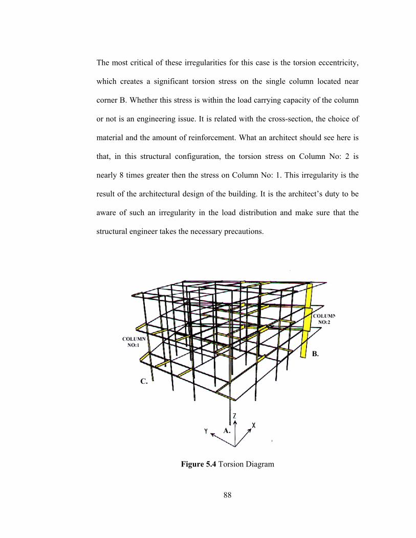
The most critical of these irregularities for this case is the torsion eccentricity,
which creates a significant torsion stress on the single column located near
corner B. Whether this stress is within the load carrying capacity of the column
or not is an engineering issue. It is related with the cross-section, the choice of
material and the amount of reinforcement. What an architect should see here is
that, in this structural configuration, the torsion stress on Column No: 2 is
nearly 8 times greater then the stress on Column No: 1. This irregularity is the
result of the architectural design of the building. It is the architect’s duty to be
aware of such an irregularity in the load distribution and make sure that the
structural engineer takes the necessary precautions.
Figure 5.4 Torsion Diagram
88
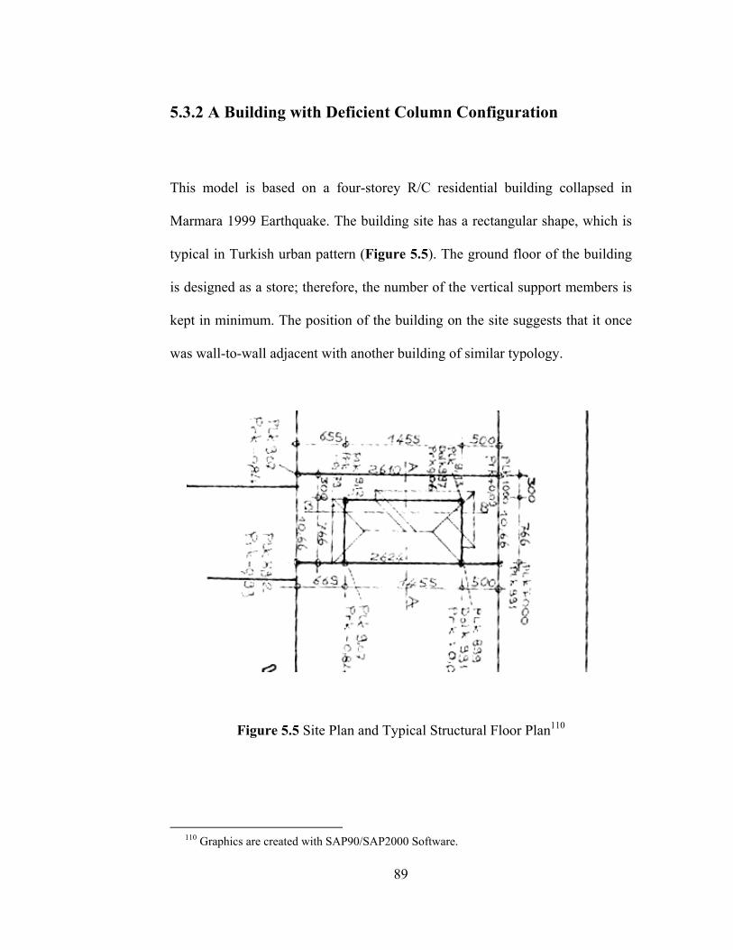
5.3.2 A Building with Deficient Column Configuration
This model is based on a four-storey R/C residential building collapsed in
Marmara 1999 Earthquake. The building site has a rectangular shape, which is
typical in Turkish urban pattern (Figure 5.5). The ground floor of the building
is designed as a store; therefore, the number of the vertical support members is
kept in minimum. The position of the building on the site suggests that it once
was wall-to-wall adjacent with another building of similar typology.
Figure 5.5 Site Plan and Typical Structural Floor Plan110
110 Graphics are created with SAP90/SAP2000 Software.
89
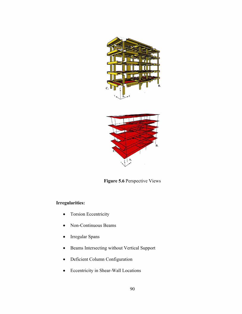
Figure 5.6 Perspective Views
Irregularities:
• Torsion Eccentricity
• Non-Continuous Beams
• Irregular Spans
• Beams Intersecting without Vertical Support
• Deficient Column Configuration
• Eccentricity in Shear-Wall Locations
90
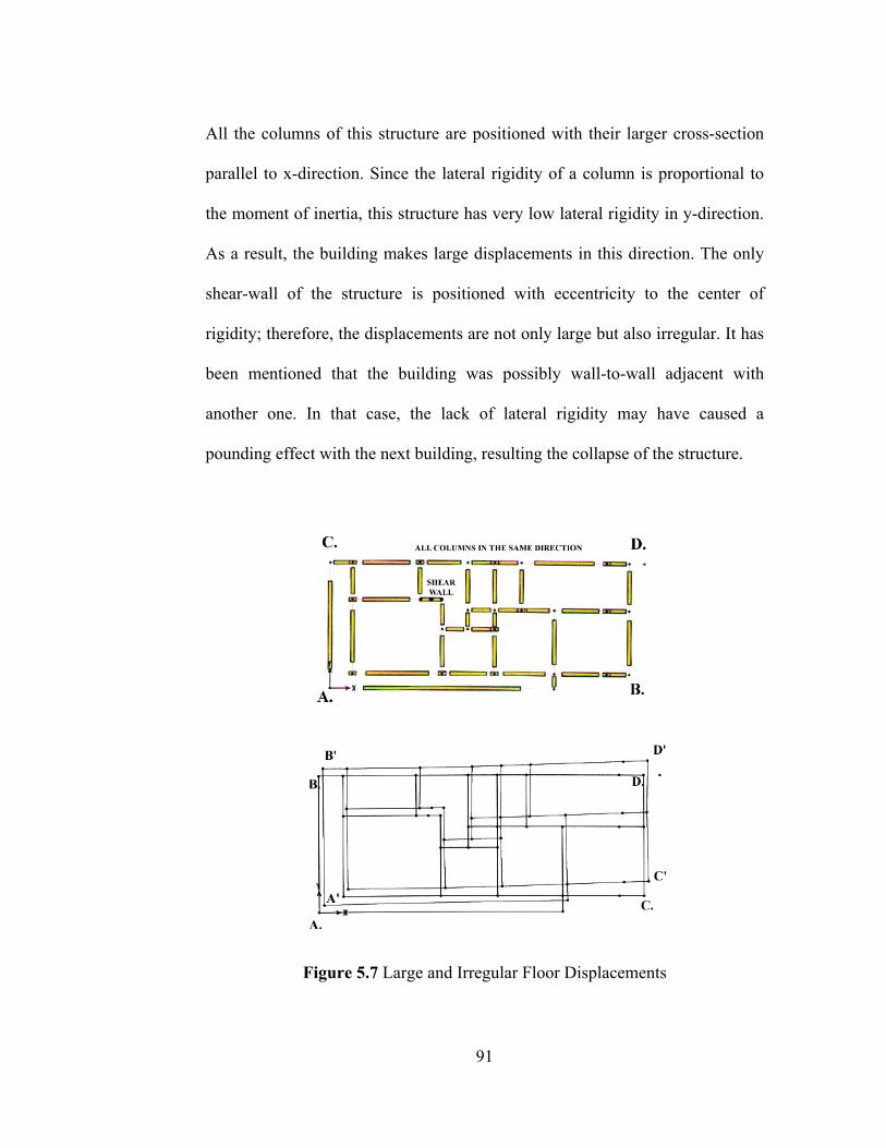
All the columns of this structure are positioned with their larger cross-section
parallel to x-direction. Since the lateral rigidity of a column is proportional to
the moment of inertia, this structure has very low lateral rigidity in y-direction.
As a result, the building makes large displacements in this direction. The only
shear-wall of the structure is positioned with eccentricity to the center of
rigidity; therefore, the displacements are not only large but also irregular. It has
been mentioned that the building was possibly wall-to-wall adjacent with
another one. In that case, the lack of lateral rigidity may have caused a
pounding effect with the next building, resulting the collapse of the structure.
Figure 5.7 Large and Irregular Floor Displacements
91
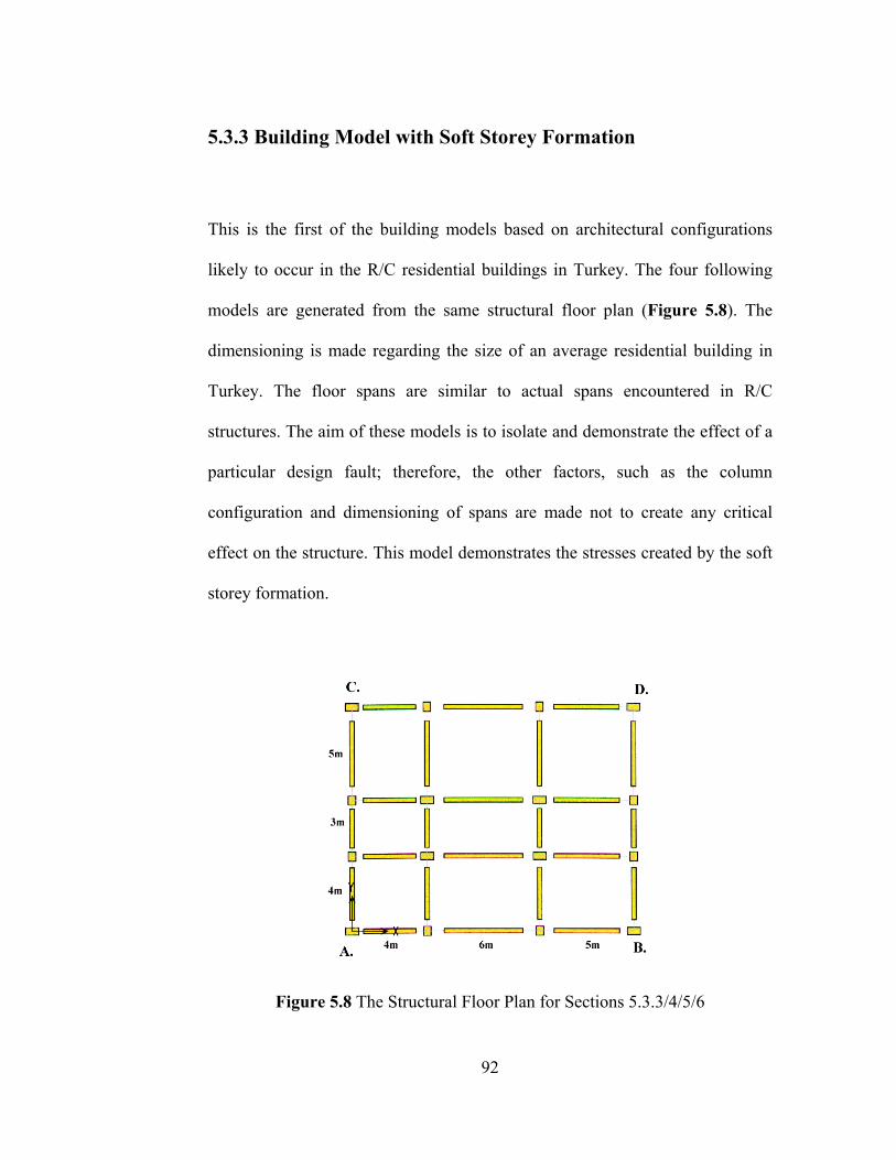
5.3.3 Building Model with Soft Storey Formation
This is the first of the building models based on architectural configurations
likely to occur in the R/C residential buildings in Turkey. The four following
models are generated from the same structural floor plan (Figure 5.8). The
dimensioning is made regarding the size of an average residential building in
Turkey. The floor spans are similar to actual spans encountered in R/C
structures. The aim of these models is to isolate and demonstrate the effect of a
particular design fault; therefore, the other factors, such as the column
configuration and dimensioning of spans are made not to create any critical
effect on the structure. This model demonstrates the stresses created by the soft
storey formation.
Figure 5.8 The Structural Floor Plan for Sections 5.3.3/4/5/6
92
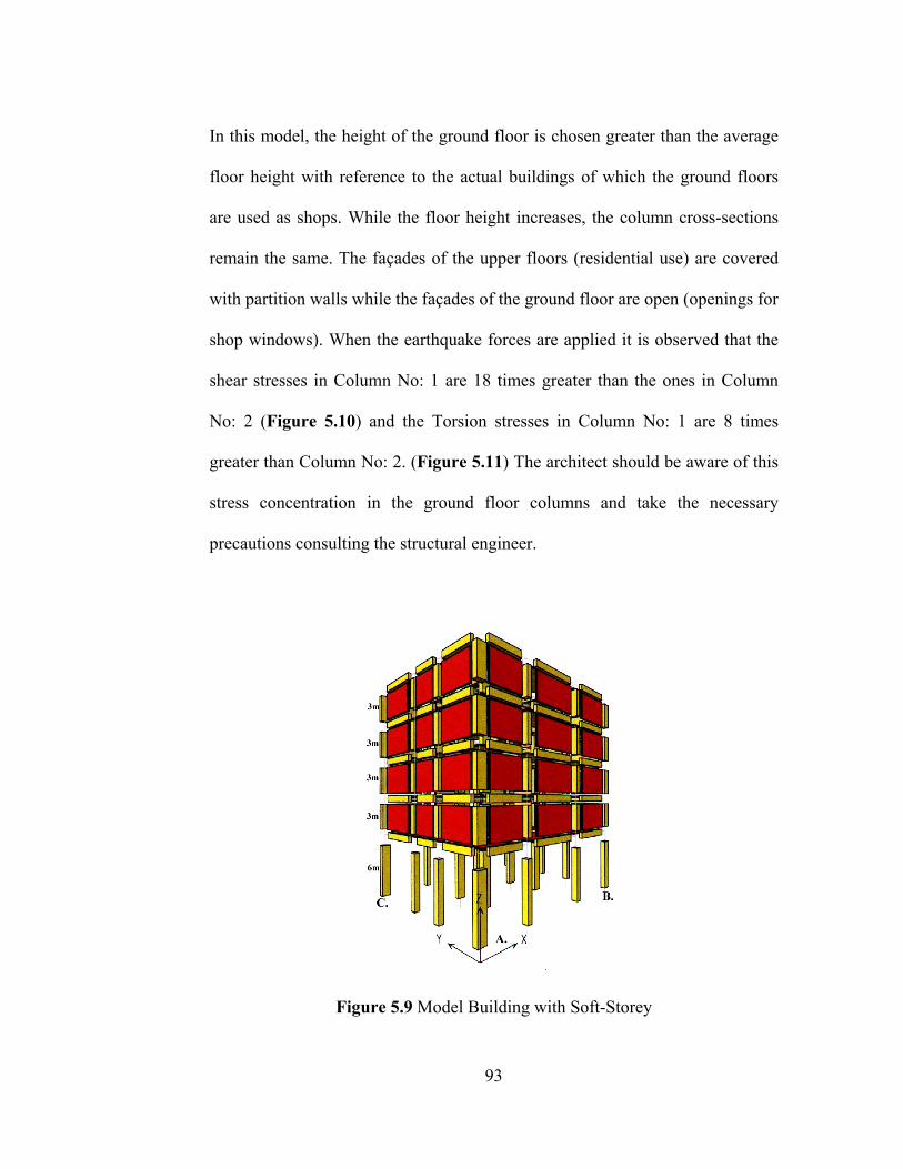
In this model, the height of the ground floor is chosen greater than the average
floor height with reference to the actual buildings of which the ground floors
are used as shops. While the floor height increases, the column cross-sections
remain the same. The façades of the upper floors (residential use) are covered
with partition walls while the façades of the ground floor are open (openings for
shop windows). When the earthquake forces are applied it is observed that the
shear stresses in Column No: 1 are 18 times greater than the ones in Column
No: 2 (Figure 5.10) and the Torsion stresses in Column No: 1 are 8 times
greater than Column No: 2. (Figure 5.11) The architect should be aware of this
stress concentration in the ground floor columns and take the necessary
precautions consulting the structural engineer.
Figure 5.9 Model Building with Soft-Storey
93

Figure 5.10 Shear Force Diagram
Figure 5.11 Torsion Diagram
94
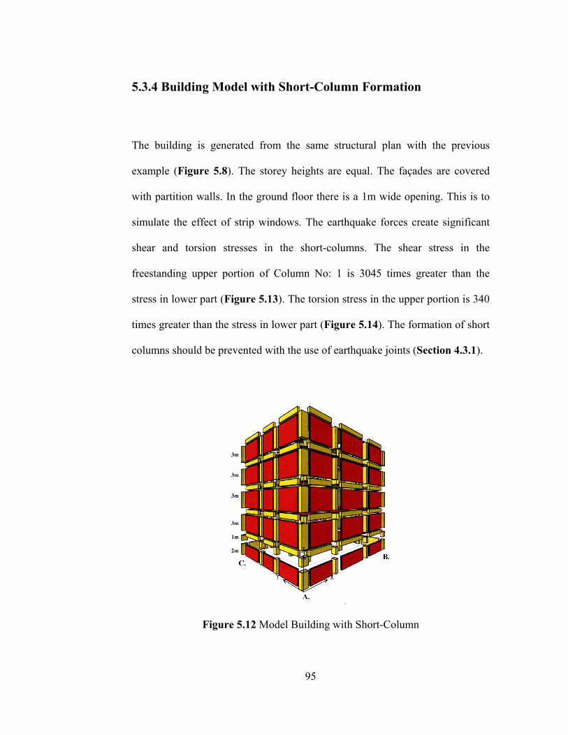
5.3.4 Building Model with Short-Column Formation
The building is generated from the same structural plan with the previous
example (Figure 5.8). The storey heights are equal. The façades are covered
with partition walls. In the ground floor there is a 1m wide opening. This is to
simulate the effect of strip windows. The earthquake forces create significant
shear and torsion stresses in the short-columns. The shear stress in the
freestanding upper portion of Column No: 1 is 3045 times greater than the
stress in lower part (Figure 5.13). The torsion stress in the upper portion is 340
times greater than the stress in lower part (Figure 5.14). The formation of short
columns should be prevented with the use of earthquake joints (Section 4.3.1).
Figure 5.12 Model Building with Short-Column
95

Figure 5.13 Shear-Force Diagram
Figure 5.14 Torsion Diagram
96
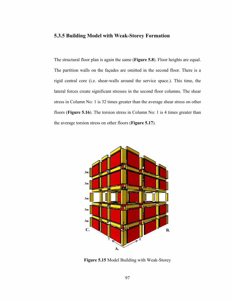
5.3.5 Building Model with Weak-Storey Formation
The structural floor plan is again the same (Figure 5.8). Floor heights are equal.
The partition walls on the façades are omitted in the second floor. There is a
rigid central core (i.e. shear-walls around the service space.). This time, the
lateral forces create significant stresses in the second floor columns. The shear
stress in Column No: 1 is 32 times greater than the average shear stress on other
floors (Figure 5.16). The torsion stress in Column No: 1 is 4 times greater than
the average torsion stress on other floors (Figure 5.17).
Figure 5.15 Model Building with Weak-Storey
97
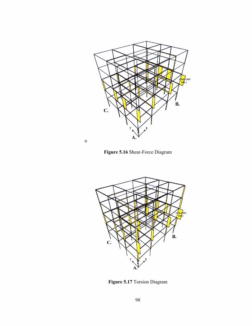
o
Figure 5.16 Shear-Force Diagram
Figure 5.17 Torsion Diagram
98

5.3.6 Building Model with Shear-Wall Eccentricity
In this model the partition walls are omitted in all floors. There is a rigid core
near the corner C. of the building (i.e. shear-walls around the service space.).
The structural behavior of this model is similar to the buildings with curtain-
walls. Under earthquake forces we observe that the shear and torsion stresses
significantly increase in the structural elements far from the rigid core (near
corner A.). The shear stress in Column No: 1 is 6 times greater than the shear
stress in Column No: 2 (Figure 5.19). The torsion stress in Column No: 2 is
two times greater than the torsion stress in Column No: 2 (Figure 5.20).
Figure 5.18 Model Building with Shear-Wall Eccentricity
99
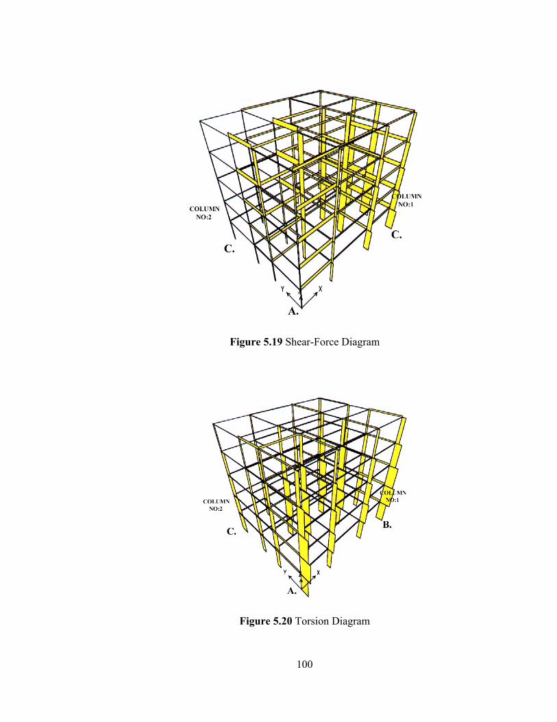
Figure 5.19 Shear-Force Diagram
Figure 5.20 Torsion Diagram
100
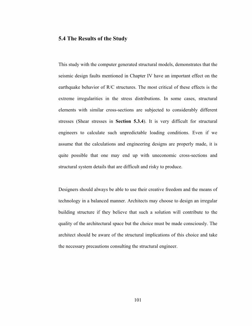
5.4 The Results of the Study
This study with the computer generated structural models, demonstrates that the
seismic design faults mentioned in Chapter IV have an important effect on the
earthquake behavior of R/C structures. The most critical of these effects is the
extreme irregularities in the stress distributions. In some cases, structural
elements with similar cross-sections are subjected to considerably different
stresses (Shear stresses in Section 5.3.4). It is very difficult for structural
engineers to calculate such unpredictable loading conditions. Even if we
assume that the calculations and engineering designs are properly made, it is
quite possible that one may end up with uneconomic cross-sections and
structural system details that are difficult and risky to produce.
Designers should always be able to use their creative freedom and the means of
technology in a balanced manner. Architects may choose to design an irregular
building structure if they believe that such a solution will contribute to the
quality of the architectural space but the choice must be made consciously. The
architect should be aware of the structural implications of this choice and take
the necessary precautions consulting the structural engineer.
101
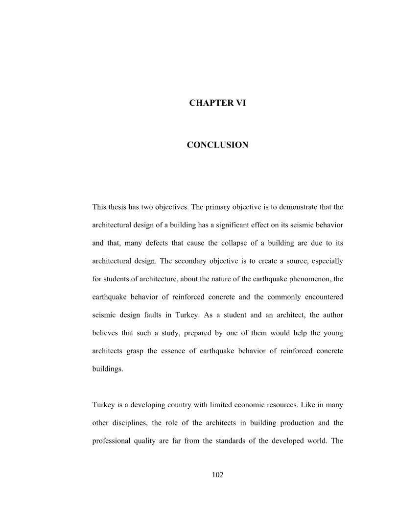
CHAPTER VI
CONCLUSION
This thesis has two objectives. The primary objective is to demonstrate that the
architectural design of a building has a significant effect on its seismic behavior
and that, many defects that cause the collapse of a building are due to its
architectural design. The secondary objective is to create a source, especially
for students of architecture, about the nature of the earthquake phenomenon, the
earthquake behavior of reinforced concrete and the commonly encountered
seismic design faults in Turkey. As a student and an architect, the author
believes that such a study, prepared by one of them would help the young
architects grasp the essence of earthquake behavior of reinforced concrete
buildings.
Turkey is a developing country with limited economic resources. Like in many
other disciplines, the role of the architects in building production and the
professional quality are far from the standards of the developed world. The
102
majority of the R/C buildings built in this country are mass-produced by
ignorant contractors without the real involvement of an architect. The market is
full of architects who sell their signatures without any sense of professional
ethics. Even when a building is truly designed by an architect there is always
the powerful influence of the project owner whose primary concern is to make
the maximum profit even at the expense of compromising the security of
human life. However, none of the factors stated above can be an excuse of
ignorance for a self-respecting member of the community of architects. As the
members of a society, which is a candidate for the European Union
membership, it is a personal duty to make one’s best to achieve the finest
standard in one’s discipline.
The message of this thesis shouldn’t be confused. This thesis doesn’t claim that
an architect should have the structural knowledge of an engineer, nor does it
say that earthquake resistant building design is solely an architectural issue.
This thesis states that the design of an earthquake resistant building starts in the
drawing table of the architects, who should have the necessary amount of
structural knowledge to evaluate the structural implications of their
architectural decisions. The grasp of the architect about the seismic behavior of
a building is and should be mostly intuitive but to acquire this intuition an
architect must have at least a basic knowledge of the earthquake phenomenon
and the how it effects the structures. The most efficient way of designing an
earthquake resistant building is the full co-operation between the structural
103
engineers and the architects. This co-operation can only be provided if the
engineers and the architects are able to speak each other’s language.
Earthquake should be considered as the judgment day for everyone involved in
the building construction sector from architects to engineers; from contractors
to construction workers. An earthquake doesn’t care about the awards that an
architect has won; it doesn’t care about the beauty or the elegance of the design.
The philosophy of the building becomes meaningless when the earthquake
strikes. Only one thing is important and that is the strength of the structure.
Architects can only design an earthquake resistant building if they are familiar
with the dynamics of seismic behavior. Earthquake resistant building design is
one of the rare moments in architecture where only knowledge matters. It is the
moral obligation and the duty of an architect to acquire this knowledge.
In conclusion, there is a lot to be done to establish the tradition of making
earthquake resistant buildings in Turkey. If one considers the various factors
and the amount of politics involved in the construction industry, it would be
unrealistic to think that the building quality will dramatically increase in a short
period of time. Reaching this target requires a lot of effort and it is easy to be
discouraged on the way; however, one shouldn’t forget that the price for
ignorance is the loss of human lives. This thesis hopes to take one more step in
creating a higher standard in Turkish architecture.
104
BIBLIOGRAPHY
• Afet İşleri Genel Müdürlüğü, Kanunlar ve Yönetmelikler. Ankara:
T.C. Bayındırlık ve İskan Bakanlığı Pub. 1998.
• Aktüre, Teoman. Deprem Güvenli Yapı Sempozyumu. Ankara:
MESA Pub. 1999
• Ambrose, James., Vergun, Dimitry. Seismic Design of Buildings.
U.S.A: John Wiley & Sons Inc. 1985
• Arısoy, E. Sami. Çünkü, Bu Yaşananlar Nasıl Olsa Bir Rüyaydı.
İstanbul: Nobel Tıp Kitabevleri Pub. 2001.
• Atımtay, Ergin. Reinforced Concrete Fundamentals. 2 vols. Ankara:
Bizim Büro Basımevi Pub., February 1998. Vol. 1 & 2
• Atımtay, Ergin. Açıklamalar ve Örneklerle Afet Bölgelerinde
Yapılacak Yapılar Hakkında Yönetmelik. 2 vols. Ankara: Bizim
Büro Basımevi Pub. 2000. Vol. 1 & 2
• Atımtay, Ergin. Çerçeveli ve Perdeli Betonarme Sistemlerin
Tasarımı. 2 vols. Ankara: METU Press, July 2001, Vol. 1 & 2.
105
• Bayülke, Nejat. ed. Depremler ve Depreme Dayanıklı Yapılar.
Ankara: T.C. İmar ve İskan Bakanlığı Deprem Araştırma Enstitüsü
Başkanlığı Pub. 1978.
• Bayülke, Nejat. Depremler ve Depreme Dayanıklı Yapılar. Ankara:
Teknik Yayınevi Pub. 1998.
• Celep, Zekai. Kumbasar, Nahit. Deprem Mühendisliğine Giriş ve
Depreme Dayanıklı Yapı Tasarımı. İstanbul: Beta Dağıtım Pub.
2000.
• Demirtaş, Ramazan. ed., 17 Ağustos 1999 İzmit Körfezi Depremi
Raporu. Ankara: January 2000.
• Erkoç, Turan. Baran, Belgin. Hamzaçebi, Gülşah. Deprem Nedir?.
Ankara: 2000.
• Gönençen, Kaya. Mimari Proje Tasarımında Depreme Karşı Yapı
Davranışının Düzenlenmesi. Ankara: Teknik Yayınevi Pub. 2000.
• Gültek Göktürk. 1995 Kobe Depremi. Ankara: TMMOB Mimarlar
Odası Ankara Şubesi Pub. 1999.
• Hasol, Doğan. Ansiklopedik Mimarlık Sözlüğü. 6th ed. İstanbul:
Yapı-Endüstri Merkezi Pub. 1995.
• Karaesmen, Erhan. ed. “Depremler ve Türkiye’nin Depremselliği”,
Deprem ve Sonrası. Ankara: Türkiye Müteahhitler Birliği Pub. 1996.
• Karaesmen, Erhan. & Buğdaycıoğlu, B. Elif. Yapısal Hasar Türleri
ve Ek Hasarı Arttırıcı Unsurlar. N.p.
106
• Kurtay, Cüneyt. 17 Ağustos 1999 Körfez Depremi Raporu. Ankara:
TMMOB Mimarlar Odası Ankara Şubesi Pub. 1999.
• Levy, Matthys. Deprem Kuşağı. İstanbul: Doğan Kitapçılık Pub.
2000
• Orman, Kemal. trans. Earthquake Architecture. By Belén Garcia. ed.
İstanbul: Tasarım Yayın Grubu Pub. 2001.
• Saları, Nasrın. Mimari Form ve Elemanlatın Depreme Dayanıklı
Yapı Tasarımına Etkileri. Graduate Thesis, Trabzon: Karadeniz
Teknik Üniversitesi Pub, 1999.
• Sucuoğlu, Haluk. “Yapılarda Deprem Kuvvetlerinin Oluşması”,
Deprem ve Sonrası. Erhan Karaesmen ed. Ankara: Türkiye
Müteahhitler Birliği Pub. 1996.
• Tezcan, Semih. S. Depreme Dayanıklı Yapı İçin Bir Mimarın Seyir
Defteri. İstanbul: Turkish Earthquake Foundation Pub., 1998.
• Tuna, Mehmet Emin, Depreme Dayanıklı Yapı Tasarımı. Ankara:
Tuna Eğitim ve Kültür Vakfı Pub. November 2000.
• Turkish Earthquake Code. Afet Bölgelerinde Yapılacak Yapılar
Hakkında Yönetmelik. Ankara: 1998.
• Ünal, Erol. 13 Mart 1992 Erzincan Depremi. Ankara: T.C.
Bayındırlık ve İskan Bakanlığı Pub. 1993
107
• Ünay, İ. Ali. “Mimari Tasarımda Deprem Bilincinin Geliştirilmesi”
Mimarlık No:290 1999.
• Ünay, İ, Ali. “Developing Earthquake Consciousness in the
Architect” Les Cahiers de l’Enseignement de L’Architecture. No:5
• Yıldırım, F. Kemal. Yapı Denetimi ve Deprem Mevzuatı. Ankara:
Teknik Yayınevi Pub. 2001
• Yılmaz, Rüçhan. and Demirtaş, Ramazan. “Depremler ve
Türkiye’nin Depremselliği”, Deprem ve Sonrası. Erhan Karaesmen
ed. Ankara: Türkiye Müteahhitler Birliği Pub. 1996.
108