Common Mistakes Made in Certification Specifications and ...
CERN-ACC-2013-019
HiLumi LHCFP7 High Luminosity Large Hadron Collider Design Study
Milestone Report
COMMON SPECIFICATIONS FOR THEALTERNATIVE PROPOSALS OF
COMPACT CRAB CAVITY GEOMETRIES
R. Calaga, O. Capatina, E. Jensen
10 June 2013
The HiLumi LHC Design Study is included in the High Luminosity LHC project and ispartly funded by the European Commission within the Framework Programme 7
Capacities Specific Programme, Grant Agreement 284404.
This work is part of HiLumi LHC Work Package 4: Crab cavities.
The electronic version of this HiLumi LHC Publication is available via the HiLumi LHC web site<http://hilumilhc.web.cern.ch> or on the CERN Document Server at the following URL:
<http://cds.cern.ch/search?p=CERN-ACC-2013-019>
CERN-ACC-2013-019

COMMON SPECIFICATIONS FOR THE
ALTERNATIVE PROPOSALS OF
COMPACT CRAB CAVITY GEOMETRIES
Grant Agreement 284404 PUBLIC 1 / 15
Grant Agreement No: 284404
HILUMI LHC FP7 High Luminosity Large Hadron Collider Design Study
Seventh Framework Programme, Capaci t ies Spec i f ic Programme, Research In f rast ructu res,
Col laborat i ve Pro ject , Des ign Study
MILESTONE REPORT
COMMON SPECIFICATIONS FOR THE
ALTERNATIVE PROPOSALS OF
COMPACT CRAB CAVITY GEOMETRIES
MILESTONE: MS45
Document identifier: HILUMILHC-MS45
Due date of deliverable: End of Month 12 (October 2012)
Report release date: 10/06/13
Work package: WP4: Crab Cavities
Lead beneficiary: CERN
Document status: Final
Abstract:
This document summarizes the common function specifications for the proposals of Compact
Crab Cavity geometries under consideration for the LHC crab crossing scheme.

COMMON SPECIFICATIONS FOR THE
ALTERNATIVE PROPOSALS OF
COMPACT CRAB CAVITY GEOMETRIES
Grant Agreement 284404 PUBLIC 2 / 15
Copyright notice:
Copyright © HiLumi LHC Consortium, 2013
For more information on HiLumi LHC, its partners and contributors please see www.cern.ch/HiLumiLHC
The HiLumi LHC Design Study is included in the High Luminosity LHC project and is partly funded by the
European Commission within the Framework Programme 7 Capacities Specific Programme, Grant Agreement
284404. HiLumi LHC began in November 2011 and will run for 4 years.
The information herein only reflects the views of its authors and not those of the European Commission and no
warranty expressed or implied is made with regard to such information or its use.
Delivery Slip
Name Partner Date
Authored by R. Calaga, O. Capatina, E. Jensen CERN 06/05/2013
Edited by R. Calaga CERN 07/05/2013
Reviewed by
L. Rossi [Project Coordinator]
E. Jensen [WP coordinator]
CERN 20/05/2013
Approved by L. Rossi [Project Coordinator] 23/05/2013

COMMON SPECIFICATIONS FOR THE
ALTERNATIVE PROPOSALS OF
COMPACT CRAB CAVITY GEOMETRIES
Grant Agreement 284404 PUBLIC 3 / 15
TABLE OF CONTENTS
1. INTRODUCTION ........................................................................................................................................ 4
2. CAVITY SPECIFICATIONS ..................................................................................................................... 5
2.1. CRAB CAVITY LAYOUR FOR HL-LHC ...................................................................................................... 5 2.2. GEOMETRY CONSTRAINTS ....................................................................................................................... 5 2.3. FREQUENCY, GRADIENT & QUALITY FACTOR ......................................................................................... 6 2.4. OPERATING TEMPERATURE ..................................................................................................................... 7 2.5. RF MULTIPOLES & COUPLER KICKS & LIMITS ........................................................................................ 8 2.6. IMPEDANCE BUDGET & HOM POWER ..................................................................................................... 8 2.7. CHEMICAL AND HEAT TREATMENT ......................................................................................................... 9 2.8. HIGH PRESSURE WATER RINSE & DEGREASING .................................................................................... 10 2.9. LEAK TIGHTNESS................................................................................................................................... 10
3. SPECIFICATIONS OF CAVITY ENCLOSURES ................................................................................. 10
3.1. CAVITY TUNER ...................................................................................................................................... 10 3.2. PRESSURE VESSEL CODE ....................................................................................................................... 11 3.3. HELIUM TANK ....................................................................................................................................... 13 3.4. STATIC MAGNETIC FIELD SHIELDING .................................................................................................... 13 3.5. CAVITY ALIGNMENT ............................................................................................................................. 14 3.6. INSTRUMENTATION ............................................................................................................................... 15
4. CONCLUSION ........................................................................................................................................... 15
5. REFERENCES ........................................................................................................................................... 15
ANNEX: GLOSSARY ........................................................................................................................................ 15

COMMON SPECIFICATIONS FOR THE
ALTERNATIVE PROPOSALS OF
COMPACT CRAB CAVITY GEOMETRIES
Grant Agreement 284404 PUBLIC 4 / 15
Executive summary
The commons functional specifications for the Compact Cavity geometries under
consideration for the LHC crab crossing scheme is described. These specifications are
derived with input from experts from CERN, EuCARD and LARP.
1. INTRODUCTION
The use of transverse deflecting cavities (crab cavities) was proposed to correct the
geometric effects of the wider crossing angles as a consequence of the reduced beam sizes
with the HL-LHC upgrade. Due to the tight geometrical and RF constraints in the LHC
interaction region (IR), an intense R&D program with collaborations from EuCARD and
LARP were put in place to design deflecting cavities compatible with the LHC footprint and
requirements.
The present document describes the functional specifications for the superconducting
compact deflecting cavities foreseen for the LHC crab-crossing scheme. General guidelines and
requirements on the fabrication of the cavity and other equipment to comply with the CERN
regulations are described with a focus on the prototype cavity tests in the SPS as a first
validation step prior to a full installation in the LHC.
COMMON SPECIFICATIONS FOR THE
ALTERNATIVE PROPOSALS OF
COMPACT CRAB CAVITY GEOMETRIES
Grant Agreement 284404 PUBLIC 5 / 15
2. CAVITY SPECIFICATIONS
2.1. CRAB CAVITY LAYOUR FOR HL-LHC
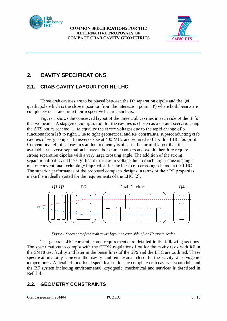
Three crab cavities are to be placed between the D2 separation dipole and the Q4
quadrupole which is the closest position from the interaction point (IP) where both beams are
completely separated into their respective beam chambers.
Figure 1 shows the concieved layout of the three crab cavities in each side of the IP for
the two beams. A staggered configuration for the cavities is chosen as a default scenario using
the ATS optics scheme [1] to equalize the cavity voltages due to the rapid change of β-
functions from left to right. Due to tight geometrical and RF constraints, superconducting crab
cavities of very compact transverse size at 400 MHz are required to fit within LHC footprint.
Conventional elliptical cavities at this frequency is atleast a factor of 4 larger than the
available transverse separation between the beam chambers and would therefore require
strong separation dipoles with a very large crossing angle. The addition of the strong
separation dipoles and the significant increase in voltage due to much larger crossing angle
makes conventional technology impractical for the local crab crossing scheme in the LHC.
The superior performance of the proposed compacts designs in terms of their RF properties
make them ideally suited for the requirements of the LHC [2].
Figure 1 Schematic of the crab cavity layout on each side of the IP (not to scale).
The general LHC constraints and requirements are detailed in the following sections.
The specifications to comply with the CERN regulations first for the cavity tests with RF in
the SM18 test facility and later in the beam lines of the SPS and the LHC are outlined. These
specifications only concern the cavity and enclosures close to the cavity at cryogenic
temperatures. A detailed functional specification for the complete crab cavity cryomodule and
the RF system including environmental, cryogenic, mechanical and services is described in
Ref. [3].
2.2. GEOMETRY CONSTRAINTS
Q1-Q3 Q4 Crab Cavities D2
COMMON SPECIFICATIONS FOR THE
ALTERNATIVE PROPOSALS OF
COMPACT CRAB CAVITY GEOMETRIES
Grant Agreement 284404 PUBLIC 6 / 15
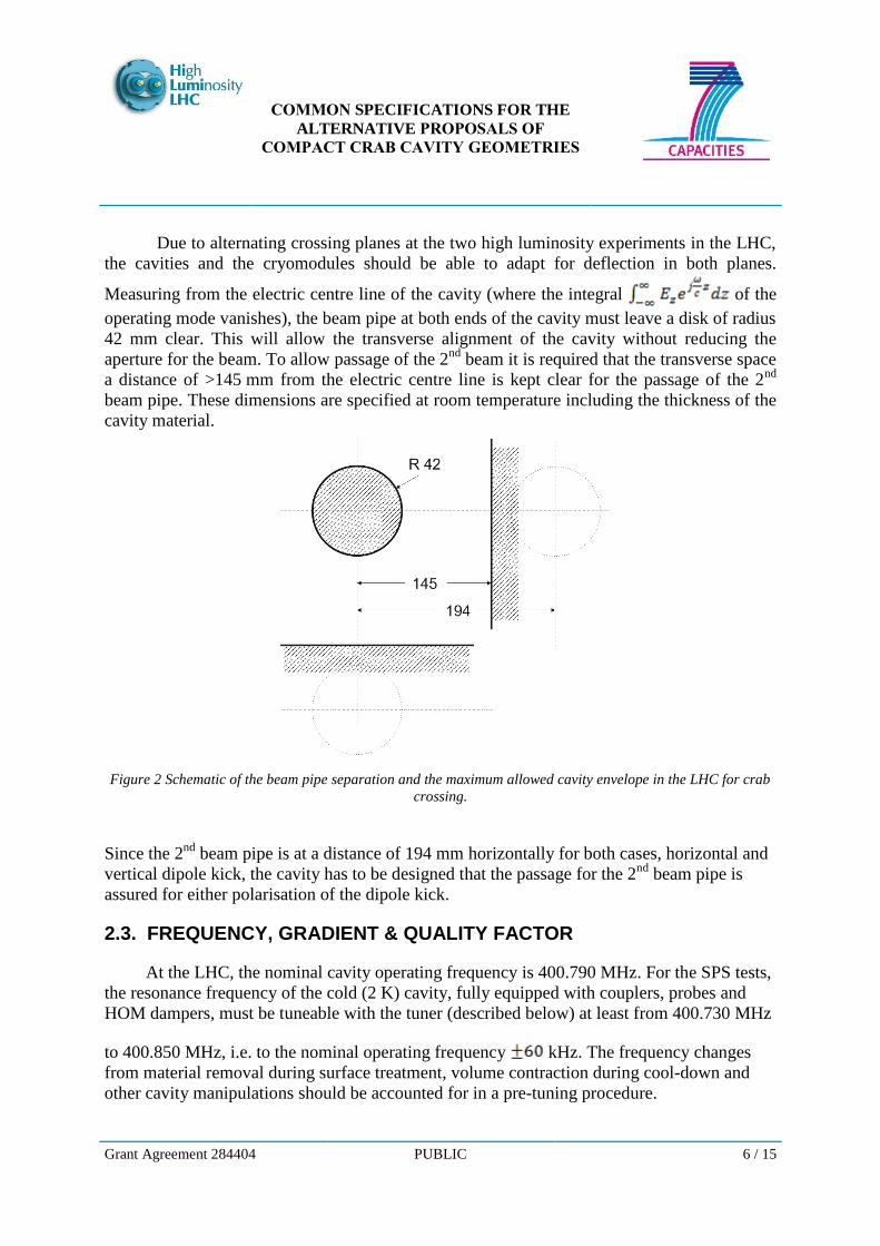
Due to alternating crossing planes at the two high luminosity experiments in the LHC,
the cavities and the cryomodules should be able to adapt for deflection in both planes.
Measuring from the electric centre line of the cavity (where the integral of the
operating mode vanishes), the beam pipe at both ends of the cavity must leave a disk of radius
42 mm clear. This will allow the transverse alignment of the cavity without reducing the
aperture for the beam. To allow passage of the 2nd
beam it is required that the transverse space
a distance of >145 mm from the electric centre line is kept clear for the passage of the 2nd
beam pipe. These dimensions are specified at room temperature including the thickness of the
cavity material.
Figure 2 Schematic of the beam pipe separation and the maximum allowed cavity envelope in the LHC for crab
crossing.
Since the 2nd
beam pipe is at a distance of 194 mm horizontally for both cases, horizontal and
vertical dipole kick, the cavity has to be designed that the passage for the 2nd
beam pipe is
assured for either polarisation of the dipole kick.
2.3. FREQUENCY, GRADIENT & QUALITY FACTOR
At the LHC, the nominal cavity operating frequency is 400.790 MHz. For the SPS tests,
the resonance frequency of the cold (2 K) cavity, fully equipped with couplers, probes and
HOM dampers, must be tuneable with the tuner (described below) at least from 400.730 MHz
to 400.850 MHz, i.e. to the nominal operating frequency kHz. The frequency changes
from material removal during surface treatment, volume contraction during cool-down and
other cavity manipulations should be accounted for in a pre-tuning procedure.

COMMON SPECIFICATIONS FOR THE
ALTERNATIVE PROPOSALS OF
COMPACT CRAB CAVITY GEOMETRIES
Grant Agreement 284404 PUBLIC 7 / 15
The nominal cavity gradient per cavity is 3.34 MV of integrated kick resulting in a total
of 10 MV in the LHC, with 3 cavities per beam per IP side [4]. Assuming a geometry factor of
and a cavity quality factor the surface resistance . The
unloaded quality factor for the cavities should aim at reaching a total surface resistance of
for their respective geometry factors. Nominal operation with the beam on axis of the
deflecting cavity should lead to minimal or zero beam loading. Therefore, only a small amount
of RF power is required to sustain the field in the cavity. To accommodate non-zero beam
loading from inevitable orbit errors and frequency changes from external forces, the is
significantly lower. Assuming , the will be adjusted so that is
constant for all three candidates, and is defined by the available RF power and beam loading
tolerances.
Parameters for 1 cavity Value
Resonance frequency 400.790 MHz
Nominal kick voltage 3.34 MV
Residual resistance
300 … 900
Table 1 Summary of Cavity Parameters
2.4. OPERATING TEMPERATURE
The operating temperature of is chosen as a baseline for both the SPS tests and the
final LHC installation [2]. This decision was based on the availability, global cryogenic and RF
efficiency and the thermal margin available for machine protection aspects.
At a nominal voltage of 3.34 MV, of 10 n and , the dynamic heat
load per cavity due to the surface losses is at 2 K. This leads to a manageable dynamic
heat load of the final LHC system with 12 cavities per IR, even assuming a safety 50% safety
factor on additional heat load.
COMMON SPECIFICATIONS FOR THE
ALTERNATIVE PROPOSALS OF
COMPACT CRAB CAVITY GEOMETRIES
Grant Agreement 284404 PUBLIC 8 / 15
As the BCS resistance at 400 MHz and 2 K is ~1 nΩ, cavity surface resistance is
primarily dominated by the residual resistance contribution, and any improvement in surface
treatment should lead to lower surface resistances and hence reduce the dynamic heat load
proportionally.
For the SPS tests, we assume a two cavity cryostat, so the combined dynamic loss from
the cavities will be ≤6 W at 2 K. For a more detailed accounting of the heat loads from
cavities, coupler interconnects and other elements of the cryostat refer to Ref. [3].
2.5. RF MULTIPOLES & COUPLER KICKS & LIMITS
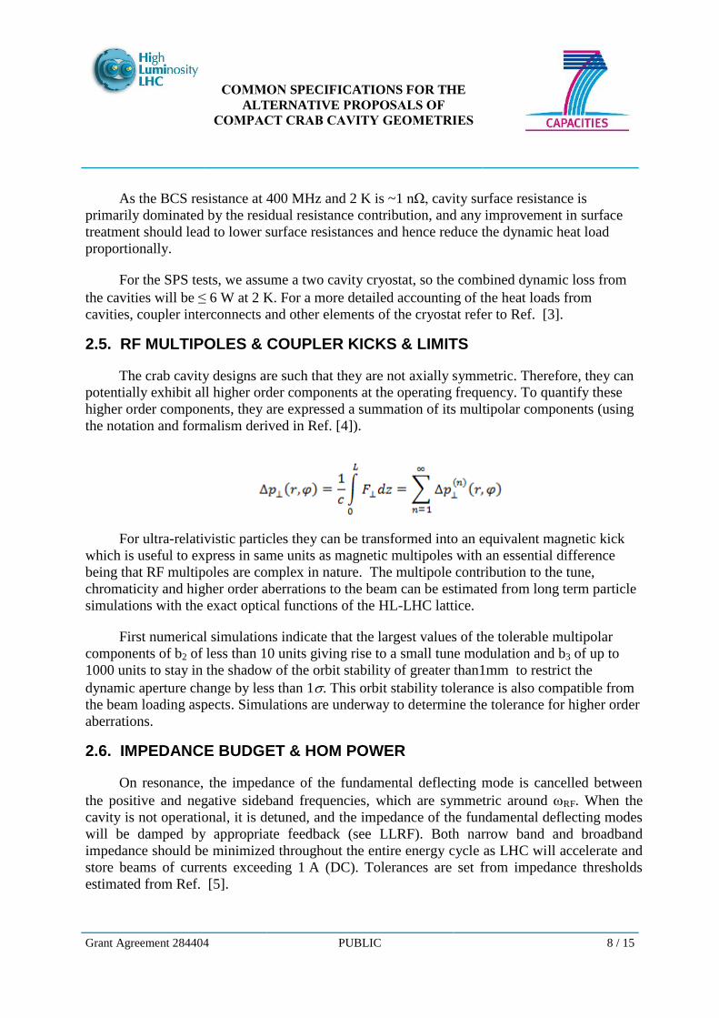
The crab cavity designs are such that they are not axially symmetric. Therefore, they can
potentially exhibit all higher order components at the operating frequency. To quantify these
higher order components, they are expressed a summation of its multipolar components (using
the notation and formalism derived in Ref. [4]).
For ultra-relativistic particles they can be transformed into an equivalent magnetic kick
which is useful to express in same units as magnetic multipoles with an essential difference
being that RF multipoles are complex in nature. The multipole contribution to the tune,
chromaticity and higher order aberrations to the beam can be estimated from long term particle
simulations with the exact optical functions of the HL-LHC lattice.
First numerical simulations indicate that the largest values of the tolerable multipolar
components of b2 of less than 10 units giving rise to a small tune modulation and b3 of up to
1000 units to stay in the shadow of the orbit stability of greater than1mm to restrict the
dynamic aperture change by less than 1. This orbit stability tolerance is also compatible from
the beam loading aspects. Simulations are underway to determine the tolerance for higher order
aberrations.
2.6. IMPEDANCE BUDGET & HOM POWER
On resonance, the impedance of the fundamental deflecting mode is cancelled between
the positive and negative sideband frequencies, which are symmetric around RF. When the
cavity is not operational, it is detuned, and the impedance of the fundamental deflecting modes
will be damped by appropriate feedback (see LLRF). Both narrow band and broadband
impedance should be minimized throughout the entire energy cycle as LHC will accelerate and
store beams of currents exceeding 1 A (DC). Tolerances are set from impedance thresholds
estimated from Ref. [5].
COMMON SPECIFICATIONS FOR THE
ALTERNATIVE PROPOSALS OF
COMPACT CRAB CAVITY GEOMETRIES
Grant Agreement 284404 PUBLIC 9 / 15
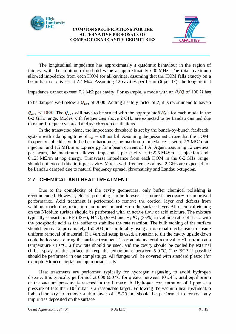
The longitudinal impedance has approximately a quadratic behaviour in the region of
interest with the minimum threshold value at approximately 600 MHz. The total maximum
allowed impedance from each HOM for all cavities, assuming that the HOM falls exactly on a
beam harmonic is set at 2.4 MΩ. Assuming 12 cavities per beam (6 per IP), the longitudinal
impedance cannot exceed 0.2 MΩ per cavity. For example, a mode with an of 100 Ω has
to be damped well below a of 2000. Adding a safety factor of 2, it is recommend to have a
. The will have to be scaled with the appropriate 's for each mode in the
0-2 GHz range. Modes with frequencies above 2 GHz are expected to be Landau damped due
to natural frequency spread and synchrotron oscillations.
In the transverse plane, the impedance threshold is set by the bunch-by-bunch feedback
system with a damping time of [5]. Assuming the pessimistic case that the HOM
frequency coincides with the beam harmonic, the maximum impedance is set at 2.7 MΩ/m at
injection and 1.5 MΩ/m at top energy for a beam current of 1 A. Again, assuming 12 cavities
per beam, the maximum allowed impedance per cavity is 0.225 MΩ/m at injection and
0.125 MΩ/m at top energy. Transverse impedance from each HOM in the 0-2 GHz range
should not exceed this limit per cavity. Modes with frequencies above 2 GHz are expected to
be Landau damped due to natural frequency spread, chromaticity and Landau octupoles.
2.7. CHEMICAL AND HEAT TREATMENT
Due to the complexity of the cavity geometries, only buffer chemical polishing is
recommended. However, electro-polishing can be foreseen in future if necessary for improved
performance. Acid treatment is performed to remove the cortical layer and defects from
welding, machining, oxidation and other impurities on the surface layer. All chemical etching
on the Niobium surface should be performed with an active flow of acid mixture. The mixture
typically consists of HF (48%), HNO3 (65%) and H3PO4 (85%) in volume ratio of 1:1:2 with
the phosphoric acid as the buffer to stabilize the rate reaction. The bulk etching of the surface
should remove approximately 150-200 µm, preferably using a rotational mechanism to ensure
uniform removal of material. If a vertical setup is used, a rotation to tilt the cavity upside down
could be foreseen during the surface treatment. To regulate material removal to ~1 m/min at a
temperature <10 °C, a flow rate should be used, and the cavity should be cooled by external
chiller spray on the surface to keep the temperature between 5-9 °C. The BCP if possible
should be performed in one complete go. All flanges will be covered with standard plastic (for
example Viton) material and appropriate seals.
Heat treatments are performed typically for hydrogen degassing to avoid hydrogen
disease. It is typically performed at 600-650 °C for greater between 10-24 h, until equilibrium
of the vacuum pressure is reached in the furnace. A Hydrogen concentration of 1 ppm at a
pressure of less than 10-7
mbar is a reasonable target. Following the vacuum heat treatment, a
light chemistry to remove a thin layer of 15-20 µm should be performed to remove any
impurities deposited on the surface.

COMMON SPECIFICATIONS FOR THE
ALTERNATIVE PROPOSALS OF
COMPACT CRAB CAVITY GEOMETRIES
Grant Agreement 284404 PUBLIC 10 / 15
2.8. HIGH PRESSURE WATER RINSE & DEGREASING
A high-pressure water rinsing procedure is mandatory to remove any dust particles and
impurities that could enhance the local surface fields and invoke field emission. It has been
established that a high-pressure water rinse has shown to improve the high field Q-slope in
several SRF cavities. All additional parts assembled into the cavity vacuum should be cleaned
appropriately to ensure cleanliness of the cavity
2.9. LEAK TIGHTNESS
A leak tightness check is to be done after all welds, surface treatments, and heat
treatments to ensure the vacuum pressure to be better than can be maintained.
For structural integrity during the cavity cool down cycle to 2 K in a vertical test cryostat, the
bare cavity under vacuum must withstand an external pressure greater than . The
CERN team will verify the mechanical stiffness of each design and recommend the
appropriate mitigation technique to ensure safety of the cavity and the environment.
3. SPECIFICATIONS OF CAVITY ENCLOSURES
3.1. CAVITY TUNER
Due to the tight transverse space constraints in the final LHC configuration, the tuning
system should be adapted to fit within the specified transverse distances. Therefore, in both
horizontal and vertical orientations, the tuner geometry should respect the LHC beam pipe
spacing of 194 mm and be compatible with any SPS envelope requirements. The tuning ranges
specified do not include the warm-to-cold frequency changes and other cavity manipulations
which should be accounted for in the design stage to arrive as close to the nominal frequency of
400.79 MHz. The cavity will be cooled by saturated superfluid helium at 2 K and about
30 mbar operating pressure. The expected pressure stability of the helium during operation is
about 1 mbar. The cavity should be designed in order to minimise the sensitivity to pressure
fluctuation, so that the induced detuning is significantly lower than the minimum cavity
bandwidth. The Lorentz detuning has also to be minimised by design, and compensation with
tuner has to ensure safe operation within the minimum cavity bandwidth.
For beam tests in the SPS a slow mechanical tuner is required to bring the cavity on
resonance in the energy range of the SPS (±60 kHz). In addition the tuner should allow for
detuning or retuning of the cavity at a safe frequency, defined in terms of including cavity
transparency and the suppression of the coupled bunch instabilities. Table below summarizes
the potential energies at which SPS can be operated for crab cavity tests and their
corresponding RF frequencies compared to that of the LHC operation.
COMMON SPECIFICATIONS FOR THE
ALTERNATIVE PROPOSALS OF
COMPACT CRAB CAVITY GEOMETRIES
Grant Agreement 284404 PUBLIC 11 / 15
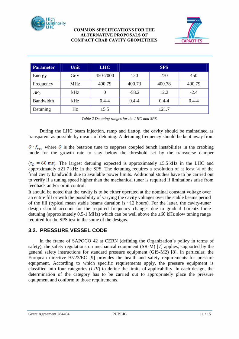
Parameter Unit LHC SPS
Energy GeV 450-7000 120 270 450
Frequency MHz 400.79 400.73 400.78 400.79
F0 kHz 0 -58.2 12.2 -2.4
Bandwidth kHz 0.4-4 0.4-4 0.4-4 0.4-4
Detuning Hz ±5.5 ±21.7
Table 2 Detuning ranges for the LHC and SPS.
During the LHC beam injection, ramp and flattop, the cavity should be maintained as
transparent as possible by means of detuning. A detuning frequency should be kept away from
where is the betatron tune to suppress coupled bunch instabilities in the crabbing
mode for the growth rate to stay below the threshold set by the transverse damper
( ). The largest detuning expected is approximately ±5.5 kHz in the LHC and
approximately ±21.7 kHz in the SPS. The detuning requires a resolution of at least ¼ of the
final cavity bandwidth due to available power limits. Additional studies have to be carried out
to verify if a tuning speed higher than the mechanical tuner is required if limitations arise from
feedback and/or orbit control.
It should be noted that the cavity is to be either operated at the nominal constant voltage over
an entire fill or with the possibility of varying the cavity voltages over the stable beams period
of the fill (typical mean stable beams duration is ~12 hours). For the latter, the cavity-tuner
design should account for the required frequency changes due to gradual Lorentz force
detuning (approximately 0.5-1 MHz) which can be well above the ±60 kHz slow tuning range
required for the SPS test in the some of the designs.
3.2. PRESSURE VESSEL CODE
In the frame of SAPOCO 42 at CERN (defining the Organization’s policy in terms of
safety), the safety regulations on mechanical equipment (SR-M) [7] applies, supported by the
general safety instructions for standard pressure equipment (GIS-M2) [8]. In particular, the
European directive 97/23/EC [9] provides the health and safety requirements for pressure
equipment. According to which specific requirements apply, the pressure equipment is
classified into four categories (I-IV) to define the limits of applicability. In each design, the
determination of the category has to be carried out to appropriately place the pressure
equipment and conform to those requirements.
COMMON SPECIFICATIONS FOR THE
ALTERNATIVE PROPOSALS OF
COMPACT CRAB CAVITY GEOMETRIES
Grant Agreement 284404 PUBLIC 12 / 15
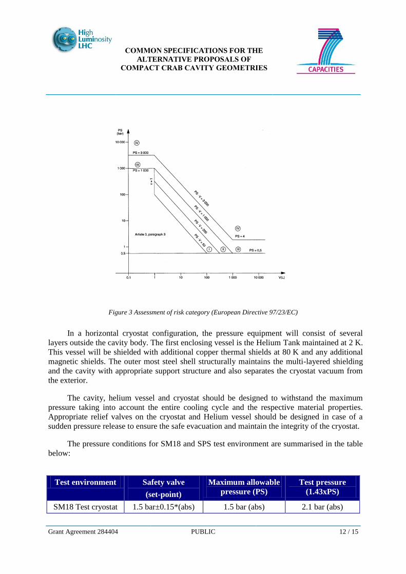
Figure 3 Assessment of risk category (European Directive 97/23/EC)
In a horizontal cryostat configuration, the pressure equipment will consist of several
layers outside the cavity body. The first enclosing vessel is the Helium Tank maintained at 2 K.
This vessel will be shielded with additional copper thermal shields at 80 K and any additional
magnetic shields. The outer most steel shell structurally maintains the multi-layered shielding
and the cavity with appropriate support structure and also separates the cryostat vacuum from
the exterior.
The cavity, helium vessel and cryostat should be designed to withstand the maximum
pressure taking into account the entire cooling cycle and the respective material properties.
Appropriate relief valves on the cryostat and Helium vessel should be designed in case of a
sudden pressure release to ensure the safe evacuation and maintain the integrity of the cryostat.
The pressure conditions for SM18 and SPS test environment are summarised in the table
below:
Test environment Safety valve
(set-point)
Maximum allowable
pressure (PS)
Test pressure
(1.43xPS)
SM18 Test cryostat 1.5 bar±0.15*(abs) 1.5 bar (abs) 2.1 bar (abs)
COMMON SPECIFICATIONS FOR THE
ALTERNATIVE PROPOSALS OF
COMPACT CRAB CAVITY GEOMETRIES
Grant Agreement 284404 PUBLIC 13 / 15
SPS 1.8 bar±0.15* (abs) 1.8 bar (abs) 2.6 bar (abs)
Table 3 Pressure conditions for the SM18 and SPS test environment.
In particular, the cavities that will undergo SPS tests have to be designed for a maximum
external pressure of . The corresponding helium tank has to be designed for a maximum
internal pressure of .
All the cryomodule assembly: cavity(ies), helium tank(s), vacuum vessel have to be
treated for the same risk category as the most critical one. From the figure above assessing the
risk category, a pressure vessel has to be treated as risk category I if the (maximum allowable
pressure fluid volume) is greater than 50 bar litre and smaller than . In
particular, for a maximum allowable pressure of , a helium tank enclosing a volume of
30 litre of helium has to be treated as risk category I.
3.3. HELIUM TANK
The baseline helium temperature used to cool the cavity is 2 K at a pressure of about
20 mbar (saturated superfluid helium). The helium tank has to be designed accordingly. In
particular, the helium tank has to be dimensioned correctly in order to extract the maximum
heat load dissipated in the cavity, since the heat flux in superfluid helium depends on the bath
temperature and on the helium channel dimension. As explained above, the helium tank for the
SPS tests has to be designed for a maximum internal pressure of .
The volume of helium to be contained by the helium tank should be minimised as much
as possible due to limitations in cryogenic infrastructure for the SPS tests. Ideally the maximum
volume should be 40 litre, however this value should not be a limitation for the design of the
helium tank.
3.4. STATIC MAGNETIC FIELD SHIELDING
Degradation of the surface resistance of the superconductor (and hence the cavity Q) can
occur due to trapped DC magnetic flux, and this can arise from stray fields in the vicinity of the
cavity or from sources such as the earth’s magnetic field. For any such external magnetic field,
the contribution to the cavity surface resistance (assuming a RRR > 250), is estimated to be
,
COMMON SPECIFICATIONS FOR THE
ALTERNATIVE PROPOSALS OF
COMPACT CRAB CAVITY GEOMETRIES
Grant Agreement 284404 PUBLIC 14 / 15
Assuming a geometric factor of approximately 100, has to be below 1-2 nΩ to
maintain the total surface resistance to below 10 nΩ. To achieve this, magnetic shielding in the
cryostat should reduce the external magnetic field on the outer surface of the cavity to below
field to achieve the desired quality factor of . For reference, in Central
Europe the Earth’s magnetic field has size of about , with a horizontal component of
and a vertical component of .
Numerical simulations with shielding material for each cavity design should be carried
out to determine the thickness and µr for the shielding material in order to achieve this
specification. The presence of ports and any openings leading to leakage should be studied in
detail. Simulations should include external stray field contributions from the LHC tunnel,
separation dipole on the IP side of the cryostat, and the Q4 quadrupole on the non-IP side. It is
recommended to evaluate the effect of internal magnetic shield close to the He-vessel and the
external warm shield in terms of both effectiveness and compactness in the transverse
dimensions. It is estimated that a shield internal to the helium tank made of CryoPerm®
( ) will have to be at least of 1 mm thick, but for effective shielding a thickness of
3 mm or larger maybe required.
3.5. CAVITY ALIGNMENT
Severe alignment constrains result from the transverse and longitudinal alignment
tolerances derived from LHC performance requirements. To summarize these constraints,
based on performance issues, are divided into the following the categories:
1. Transverse rotation of the individual cavities inside the cryostat.
a. Cavity rotation in the x-y plane introduces a parasitic crossing angle in the
non-crossing plane, thereby counter acting the crossing angle compensation as
well as giving non-closure of the crab bump in the crossing plane. To limit
this, it is required that the transverse rotation tolerance be 0.3° per cavity.
2. Tilt of the cavity with respect to the longitudinal cryostat axis.
a. Cavity tilt with respect to the cryostat axis should be less than 0.06°.
3. Transverse displacement of cavities w.r.t each other inside a cryostat.
a. Intra-cavity alignment in the transverse plane with respect to the cryostat axis
should not exceed the 0.7 mm tolerance set by the multipolar effects.
4. Longitudinal displacement of cavities w.r.t each other inside a cryostat

COMMON SPECIFICATIONS FOR THE
ALTERNATIVE PROPOSALS OF
COMPACT CRAB CAVITY GEOMETRIES
Grant Agreement 284404 PUBLIC 15 / 15
a. Longitudinal displacement of the cavities from their nominal position is
not crucial as deviation can be compensated by adjustments of the
individual cavity set point voltages to account for changes in the optical
functions. However, this displacement should be minimized to limit the
cavity voltage imbalance to less than 0.1% of the nominal voltage, which
is approximately 1-2 cm. Thus the longitudinal displacement tolerance is
set at of the cavities 10mm.
3.6. INSTRUMENTATION
The temperature of each cavity is to be monitored with thermal sensors if feasible. These
sensors are practical only for cavity tests in a vertical cryostat. In the SPS and LHC
cryomodules, temperature gauges on the Helium tank (CERNOX type transducers) will be
required. Additional gauges for pressure and Helium level are detailed in Ref. [3].
4. CONCLUSION
Functional specifications for the superconducting compact deflecting cavities for the
HL-LHC were described. Some general guidelines and requirements on the fabrication of the
cavity and other cavity enclosures to comply with the CERN regulations were also outlined.
5. REFERENCES
[1] R. de Maria et al., 5th
LHC crab cavity workshop, LHC-CC10, CERN, 2011.
[2] R. Calaga, LHC Crab Cavities, LHC performance workshop, Chamonix, 2012.
[3] P. Baudrenghien et al., Functional specifications of the LHC crab cavity system, CERN-
ACC-NOTE-2013-003, 2013.
[4] A. Grudiev et al., Study of Multipolar RF Kicks from the Main Deflecting Mode in
Compact Crab Cavities for LHC, IPAC12, New Orleans, 2012.
[5] A. Burov, E. Shaposhnikova, Impedance budgets for crab cavities, presented at LHC-
CC11, CERN, 2011.
ANNEX: GLOSSARY
Acronym Definition
HL-LHC High Luminosity Large Hadron Collider
IR Interaction region