Common Construction-Site BMPs Quick Reference Guide
9
Common Construction-Site BMPs Quick Reference Guide Installation and Inspection Requirements For more informaon visit the Town of Truckee Clean Water Program Website: hp://www.townoſtruckee.com/engineering/clean-water-program 10183 Truckee Airport Road, CA 96161 (530) 582—7700
Transcript of Common Construction-Site BMPs Quick Reference Guide

Common Construction-Site BMPs
Quick Reference Guide
Installation and Inspection Requirements
For more information visit the Town of Truckee Clean Water Program Website:
http://www.townoftruckee.com/engineering/clean-water-program
10183 Truckee Airport Road, CA 96161
(530) 582—7700

The purpose of silt fence is to retain the soil on disturbed land until the activities
disturbing the land are sufficiently completed to allow revegetation and permanent soil
SILT FENCE
A silt fence is a temporary sediment barrier made of porous fabric. It’s held up by wooden or
metal posts driven into the ground, so it’s inexpensive and relatively easy to remove. The fabric
ponds sediment-laden stormwater runoff, causing sediment to be retained by the settling pro-
cesses. A single 100 foot (ft) run of silt fence may hold 50 tons of sediment in place. Most con-
struction sites today do have silt fences. But many do not work effectively because they are not
well designed, installed, or maintained. The focus of this fact sheet is—how to make silt fences
work.
Placement is important because where a fence starts, runs, and ends is critical to its effective-
ness. Improper placement can make the fence a complete waste of money. Analyze the con-
struction site’s contours to determine the proper placement. Segment the site into manageable
sediment storage areas for using multiple silt fence runs.
Old Way—one continuous piece of fencing New Way (J-hook) —several pieces of fencing
Flow Direction
http://www.townoftruckee.com/departments/building-and-safety
http://www.townoftruckee.com/departments/engineering/clean-water-program
Silt fence Silt fence
Flow Direction

INSTALLATION
TRENCHING AND SLICING
Installing a silt fence properly requires that the bottom of the fence be trenched into the ground.
Proper installation inhibits water from undermining the fence and leaving the fence ineffectual.
Two popular methods of installation include using a slicer, which creates a thin trench and installs
the fence fabric in one pass, the other installation method uses a trencher or hand tools to cre-
ate a trench in which the fence fabric is placed. Both methods are effective but the automated
slicer, pictured below, offers a little more strength because of how the surrounding soil is not dis-
turbed during installation.
Regardless of the installation method, proper at-
tachment of the fabric to the posts is critical to
combining the strength of the fabric and support
posts into a unified structure. It must be able to
support 24” of sediment and water. For steel posts
use three plastic ties per post (50 lb test strength),
located in the top 8” of the fabric, with each tie
hung on a post nipple, placed diagonally to at-
tach as many vertical and horizontal threads as
possible. For wooden posts use several staples per
post, with a wood lath to overlay the fabric.
Metal-mesh backed fencing is necessary in areas
with anticipated heavy sediment loads, steeper
slopes and during winter [wet season (October 15-
April 15)] periods. Spacing of stakes should be 10 ft.
maximum with metal-mesh fencing and 6ft. maxi-
mum without mesh backing.
http://www.townoftruckee.com/departments/building-and-safety
http://www.townoftruckee.com/departments/engineering/clean-water-program

Fiber rolls complement permanent best management practices used for source control
and revegetation
FIBER ROLLS/STRAW WATTLES
Fiber rolls (also called fiber logs or straw wattles) are tube-shaped erosion-control devices filled
with straw, flax, rice, coconut fiber material, or composted material. Each roll is wrapped with UV
-degradable polypropylene netting for longevity or with 100 percent biodegradable materials
like burlap, jute, or coir. When installed in combination with straw mulch, erosion control blan-
kets, hydraulic mulches, or bounded fiber matrices for slope stabilization, these devices reduce
the effects of long or steep slopes. Fiber rolls also help to slow, filter, and spread overland flows.
This helps to prevent erosion and minimizes rill and gully development.
Suitable Applications:
Along the toe, top, face, and at grade breaks of
exposed and erodible slopes to shorten slope
length and spread runoff as sheet flow
At the end of a downward slope where it transi-
tions to a steeper slope
Along the perimeter of a project
As check dams in unlined ditches with minimal
grade
Down-slope of exposed soil areas
At operational storm drains as a form of inlet
protection
Around temporary stockpiles
It is critical that rolls/wattles are in-
stalled perpendicular to water move-
ment, and parallel to slope contours. Do
not install parallel to the flow path. The
rolls/wattles should be slightly over-
lapped when placed in a row.
http://www.townoftruckee.com/departments/building-and-safety
http://www.townoftruckee.com/departments/engineering/clean-water-program
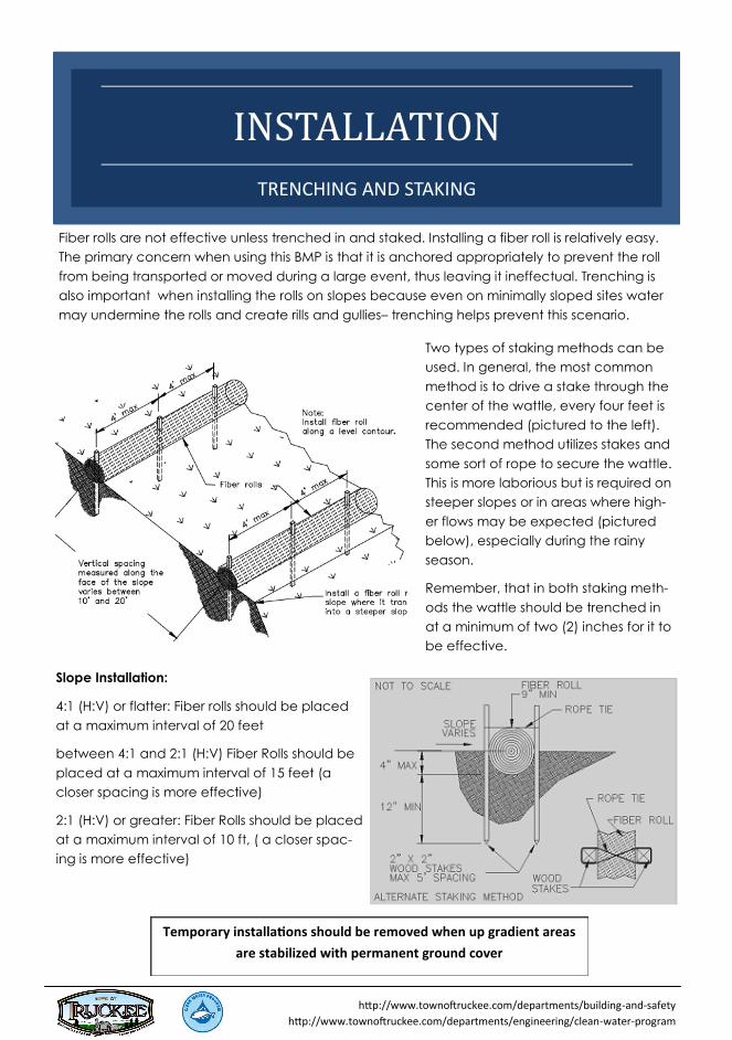
INSTALLATION
TRENCHING AND STAKING
Fiber rolls are not effective unless trenched in and staked. Installing a fiber roll is relatively easy.
The primary concern when using this BMP is that it is anchored appropriately to prevent the roll
from being transported or moved during a large event, thus leaving it ineffectual. Trenching is
also important when installing the rolls on slopes because even on minimally sloped sites water
may undermine the rolls and create rills and gullies– trenching helps prevent this scenario.
Two types of staking methods can be
used. In general, the most common
method is to drive a stake through the
center of the wattle, every four feet is
recommended (pictured to the left).
The second method utilizes stakes and
some sort of rope to secure the wattle.
This is more laborious but is required on
steeper slopes or in areas where high-
er flows may be expected (pictured
below), especially during the rainy
season.
Remember, that in both staking meth-
ods the wattle should be trenched in
at a minimum of two (2) inches for it to
be effective.
Slope Installation:
4:1 (H:V) or flatter: Fiber rolls should be placed
at a maximum interval of 20 feet
between 4:1 and 2:1 (H:V) Fiber Rolls should be
placed at a maximum interval of 15 feet (a
closer spacing is more effective)
2:1 (H:V) or greater: Fiber Rolls should be placed
at a maximum interval of 10 ft, ( a closer spac-
ing is more effective)
Temporary installations should be removed when up gradient areas
are stabilized with permanent ground cover
http://www.townoftruckee.com/departments/building-and-safety
http://www.townoftruckee.com/departments/engineering/clean-water-program

A stabilized construction access is defined by a point of entrance/exit to a construction
site that is stabilized to reduce the tracking of mud and dirt onto public roads
STABILIZED ENTRANCE/EXIT
Stabilized construction site entrances and exits should be implemented at all constructions sites.
This BMP is especially important on sites where dirt or mud can be tracked onto public roads,
adjacent to water bodies, where poor soils are encountered, where dust is a problem during dry
weather conditions, and during wet season conditions.
Stabilized Construction Site Entrances should limit
the points of entrance and exit to the construc-
tion site. All vehicles should use the designated
entrance and exit. Design of the entrance/exit
should support the heaviest of vehicles, and
should be properly graded to prevent runoff from
leaving the site.
The use of manufactured steel plates (rumble
plates) with ribs for entrance/exit access is al-
lowed and maybe a necessary secondary BMP to
the stabilized entrance/exit if off-tracking contin-
ues to occur.
Street sweeping/vacuuming may be needed if off
-tracking is persistent. Removal of sediment de-
posits on public roadways shall be removed within
24-hours
Other solutions like a longer stabilized entrance/exit area or the use of a larger aggregate (do
not exceed 6 in) may also aid if off-tracking is persistent.
Periodic top-dressing of the aggregate may be required to ensure the integrity of the entrance
during construction. Crushed Rock material shall be added when surface voids are no longer
visible.
http://www.townoftruckee.com/departments/building-and-safety
http://www.townoftruckee.com/departments/engineering/clean-water-program

Inspections:
These and all BMPs must be inspected regularly. It is rec-
ommended that they be inspected:
Monthly or more regularly,
Prior to any forecasted rain events,
Daily during extended rain events, and
After the conclusion of rain events.
INSTALLATION
DIMENSIONS AND MATERIALS
A stabilized construction site entrance /exit may vary slightly depending on the site. However,
the following elements/requirements should be used every time.
Required materials and dimensions (minimum standards):
The aggregate used shall be 2-inch crushed rock or 1 to 3 inch diameter washed well grad-
ed gravel.
The entrance shall be properly graded to prevent runoff from leaving the site
Shall be constructed on relatively level ground
Dimension must be at a minimum 50 feet in length and 24 feet wide with a radius of 10 feet
The depth shall be at a minimum 6 inches
Optional materials:
If subgrade reinforcement is necessary, a geotextile fabric shall be placed under the aggre-
gate. This must be removed upon final stabilization
http://www.townoftruckee.com/departments/building-and-safety
http://www.townoftruckee.com/departments/engineering/clean-water-program
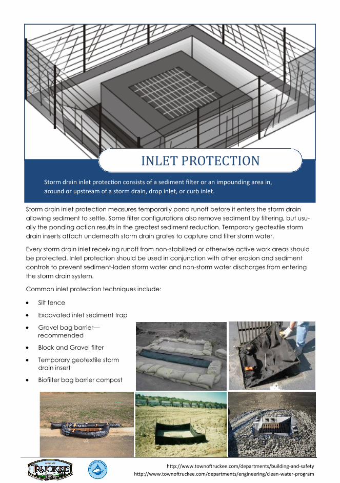
Storm drain inlet protection consists of a sediment filter or an impounding area in,
around or upstream of a storm drain, drop inlet, or curb inlet.
INLET PROTECTION
Storm drain inlet protection measures temporarily pond runoff before it enters the storm drain
allowing sediment to settle. Some filter configurations also remove sediment by filtering, but usu-
ally the ponding action results in the greatest sediment reduction. Temporary geotextile storm
drain inserts attach underneath storm drain grates to capture and filter storm water.
Every storm drain inlet receiving runoff from non-stabilized or otherwise active work areas should
be protected. Inlet protection should be used in conjunction with other erosion and sediment
controls to prevent sediment-laden storm water and non-storm water discharges from entering
the storm drain system.
Common inlet protection techniques include:
Silt fence
Excavated inlet sediment trap
Gravel bag barrier—
recommended
Block and Gravel filter
Temporary geotextile storm
drain insert
Biofilter bag barrier compost
http://www.townoftruckee.com/departments/building-and-safety
http://www.townoftruckee.com/departments/engineering/clean-water-program

INSTALLATION
TECHNIQUES AND MATERIALS
Inlet protection is the last line of defense for water quality prior to water entering the system and
being transported to a creek or stream.
Installation techniques and materials vary depending upon the type of protection being utilized.
However, certain criteria remains consistent regardless of the technique.
Required materials and techniques:
Grates and spaces around all inlets should be sealed to prevent seepage of sediment-laden
water
Provide area around the inlet for water to pond without flooding structures and property
Inspections:
Inspect Inlet protection BMP weekly (important during the rain y season)
Inspect drain inlet barriers before and after storms,
At 24-hour intervals during extended storms, and
Check to determine if sediment is by-passing the barrier during inspections.
Check for deterioration and tears of filter fabrics and bags and replace if necessary (see pic.
below)
Sediment that accumulates in the BMP should be periodically removed in order to maintain
BMP effectiveness. Sediment should be removed when the sediment accumulation reaches
one-third of the barrier height (see pic below).
Drain inlet protection needs to be removed once the construction site is stabilized and the per-
mit has been terminated. Clean and regrade area around the inlet. The area should be free of
sediment and debris at the time of final inspection.
http://www.townoftruckee.com/departments/building-and-safety
http://www.townoftruckee.com/departments/engineering/clean-water-program