Common Clock(SRAN9.0 02)
101
SingleRAN Common Clock Feature Parameter Description Issue 02 Date 2014-09-30 HUAWEI TECHNOLOGIES CO., LTD.
description
Common Clock(SRAN9.0 02)
Transcript of Common Clock(SRAN9.0 02)

SingleRAN
Common Clock Feature ParameterDescription
Issue 02
Date 2014-09-30
HUAWEI TECHNOLOGIES CO., LTD.

Copyright © Huawei Technologies Co., Ltd. 2014. All rights reserved.
No part of this document may be reproduced or transmitted in any form or by any means without prior writtenconsent of Huawei Technologies Co., Ltd. Trademarks and Permissions
and other Huawei trademarks are trademarks of Huawei Technologies Co., Ltd.All other trademarks and trade names mentioned in this document are the property of their respective holders. NoticeThe purchased products, services and features are stipulated by the contract made between Huawei and thecustomer. All or part of the products, services and features described in this document may not be within thepurchase scope or the usage scope. Unless otherwise specified in the contract, all statements, information,and recommendations in this document are provided "AS IS" without warranties, guarantees or representationsof any kind, either express or implied.
The information in this document is subject to change without notice. Every effort has been made in thepreparation of this document to ensure accuracy of the contents, but all statements, information, andrecommendations in this document do not constitute a warranty of any kind, express or implied.
Huawei Technologies Co., Ltd.Address: Huawei Industrial Base
Bantian, LonggangShenzhen 518129People's Republic of China
Website: http://www.huawei.com
Email: [email protected]
Issue 02 (2014-09-30) Huawei Proprietary and ConfidentialCopyright © Huawei Technologies Co., Ltd.
i

Contents
1 About This Document..................................................................................................................11.1 Scope..............................................................................................................................................................................11.2 Intended Audience..........................................................................................................................................................21.3 Change History...............................................................................................................................................................21.4 Differences Between Base Station Types.......................................................................................................................3
2 Overview.........................................................................................................................................5
3 Common GPS Reference Clock..................................................................................................73.1 Common GPS Reference Clock in Separate-MPT Multimode Base Stations...............................................................83.2 Common GPS Reference Clock in Co-MPT Multimode Base Stations......................................................................113.3 Common GPS Reference Clock in Hybrid-MPT Multimode Base Stations................................................................14
4 Common BITS Reference Clock...............................................................................................174.1 Common BITS Reference Clock in Separate-MPT Multimode Base Stations............................................................184.2 Common BITS Reference Clock in Co-MPT Multimode Base Stations.....................................................................204.3 Common BITS Reference Clock in Hybrid-MPT Multimode Base Stations..............................................................22
5 Common E1/T1 Reference Clock..............................................................................................245.1 Common E1/T1 Reference Clock in Separate-MPT Multimode Base Stations...........................................................255.2 Common E1/T1 Reference Clock in Co-MPT Multimode Base Stations....................................................................285.3 Common E1/T1 Reference Clock in Hybrid-MPT Multimode Base Stations.............................................................30
6 Common IEEE 1588v2 Reference Clock..................................................................................336.1 Common IEEE 1588v2 Reference Clock in Separate-MPT Multimode Base Stations...............................................356.2 Common IEEE 1588v2 Reference Clock in Co-MPT Multimode Base Stations........................................................386.3 Common IEEE 1588v2 Reference Clock in Hybrid-MPT Multimode Base Stations.................................................40
7 Common Synchronous Ethernet Reference Clock................................................................437.1 Common Synchronous Ethernet Reference Clock in Separate-MPT Multimode Base Stations.................................457.2 Common Synchronous Ethernet Reference Clock in Co-MPT Multimode Base Stations..........................................487.3 Common Synchronous Ethernet Reference Clock in Hybrid-MPT Multimode Base Stations....................................50
8 Other Common Reference Clocks............................................................................................538.1 Common 1PPS+TOD Reference Clock in Co-MPT GSM/UMTS/LTE Triple-mode Base Stations..........................548.2 Common IEEE 1588v2+SyncE Reference Clock in Co-MPT GSM/UMTS/LTE Triple-mode Base Stations...........54
SingleRANCommon Clock Feature Parameter Description Contents
Issue 02 (2014-09-30) Huawei Proprietary and ConfidentialCopyright © Huawei Technologies Co., Ltd.
ii

9 Engineering Guidelines.............................................................................................................569.1 When to Use Common Clock.......................................................................................................................................569.2 Required Information...................................................................................................................................................569.3 Requirements................................................................................................................................................................569.4 Initial Configuration.....................................................................................................................................................589.4.1 GBTS/eGBTS Providing Clock Source for NodeB/eNodeB/Co-MPT Base Station................................................589.4.2 NodeB Providing Clock Source for GBTS/eGBTS/eNodeB/Co-MPT Base Station................................................659.4.3 eNodeB Providing Clock Source for GBTS/eGBTS/NodeB/Co-MPT Base Station................................................699.4.4 Co-MPT Base Station Providing Clock Source for GBTS/eGBTS/NodeB/eNodeB................................................739.4.5 Co-MPT Base Station Supporting Common Reference Clock among GSM, UMTS, and LTE...............................789.5 Activation Observation.................................................................................................................................................809.6 Troubleshooting............................................................................................................................................................81
10 Parameters...................................................................................................................................82
11 Counters......................................................................................................................................95
12 Glossary.......................................................................................................................................96
13 Reference Documents...............................................................................................................97
SingleRANCommon Clock Feature Parameter Description Contents
Issue 02 (2014-09-30) Huawei Proprietary and ConfidentialCopyright © Huawei Technologies Co., Ltd.
iii

1 About This Document
1.1 ScopeThis document describes the Common Clock feature, which applies to the scenario in whichbaseband unit (BBU) sharing is implemented on a multimode base station. Common clocks inmultimode base stations can be classified into:
l GSM/UMTS common clock
l GSM/LTE common clock
l UMTS/LTE common clock
l GSM/UMTS/LTE common clock
With BBU sharing, boards of different modes are installed in one BBU. BBU sharing can beimplemented on one BBU or two interconnected BBUs.
For details about clock configuration of a single-mode base station, see Synchronization FeatureParameter Description for this mode. The Common Clock feature involves the followingfeatures:
l MRFD-211601 Multi-mode BS Common Reference Clock(GBTS/eGBTS)
l MRFD-221601 Multi-mode BS Common Reference Clock(NodeB)
l MRFD-231601 Multi-mode BS Common Reference Clock (eNodeB)
l MRFD-241601 Multi-mode BS Common Reference Clock(LTE TDD)
NOTE
l BTS, NodeB, and eNodeB correspond to the GSM, UMTS, and LTE modes of a multimode base station,respectively.
l Before reading this document, familiarize yourself with Synchronization Feature ParameterDescription for each mode, including eRAN, RAN, and GBSS.
l MRFD-231601 Multi-mode BS Common Reference Clock (eNodeB) is an LTE FDD feature andMRFD-241601 Multi-mode BS Common Reference Clock(LTE TDD) is an LTE TDD feature. Unlessotherwise specified, the LTE mode and eNodeB mentioned in this document do not differentiatebetween FDD and TDD.
Table 1-1 lists the definitions of all kinds of base stations.
SingleRANCommon Clock Feature Parameter Description 1 About This Document
Issue 02 (2014-09-30) Huawei Proprietary and ConfidentialCopyright © Huawei Technologies Co., Ltd.
1

Table 1-1 Definitions of base stations
Base Station Name Definition
GBTS GBTS refers to a base station deployed with GTMU.
eGBTS eGBTS refers to a base station deployed with UMPT_G.
NodeB NodeB refers to a base station deployed with WMPT orUMPT_U.
eNodeB eNodeB refers to a base station deployed with LMPT, UMPT_L,or UMPT_T.
Co-MPT MultimodeBase Station
Co-MPT multimode base station refers to a base station deployedwith UMPT_GU, UMPT_GL, UMPT_GT, UMPT_UL,UMPT_UT, UMPT_LT, UMPT_GUL, UMPT_GUT,UMPT_ULT, UMPT_GLT, or UMPT_GULT, and itfunctionally corresponds to any combination of eGBTS, NodeB,and eNodeB. For example, Co-MPT multimode base stationdeployed with UMPT_GU functionally corresponds to thecombination of eGBTS and NodeB.
Separate-MPTMultimode Base Station
Separate-MPT multimode base station refers to a base station onwhich different modes use different main control boards. Forexample, base stations deployed with GTMU and WMPT arecalled separate-MPT GSM/UMTS dual-mode base station.
1.2 Intended AudienceThis document is intended for personnel who:
l Need to understand the features described herein
l Work with Huawei products
1.3 Change HistoryThis section provides information about the changes in different document versions. There aretwo types of changes, which are defined as follows:
l Feature change
Changes in features of a specific product version
l Editorial change
Changes in wording or addition of information that was not described in the earlier version
SRAN9.0 02 (2014-09-30)
Compared with Issue 01 (2014-04-30) of SRAN9.0, 02 (2014-09-30) of SRAN9.0 includes thefollowing changes.
SingleRANCommon Clock Feature Parameter Description 1 About This Document
Issue 02 (2014-09-30) Huawei Proprietary and ConfidentialCopyright © Huawei Technologies Co., Ltd.
2

ChangeType
Change Description ParameterChange
Featurechange
Added the principles of common clock in scenarios ofBBU interconnection for separate-MPT and co-MPTbase stations. For details, see the following chapters:l 3 Common GPS Reference Clockl 4 Common BITS Reference Clockl 5 Common E1/T1 Reference Clockl 6 Common IEEE 1588v2 Reference Clockl 7 Common Synchronous Ethernet Reference
Clock
None
Editorialchange
None None
SRAN9.0 01 (2014-04-30)
This issue does not include any changes.
SRAN9.0 Draft A (2014-01-20)
Compared with Issue 01 (2013-04-28) of SRAN8.0, Draft A (2014-01-20) of SRAN9.0 includesthe following changes.
Change Type Change Description ParameterChange
Feature change Added common clocks for the LTE TDD mode.Added the description of BBU interconnection,For details, see 2 Overview.Huawei mobile network management systemM2000 is renamed U2000.
None
Editorial change Split "Common GPS/BITS Reference Clock" intotwo sections: " Common GPS Reference Clock "and " Common BITS Reference Clock".
None
1.4 Differences Between Base Station TypesLampSite base stations are distributed base stations that provide indoor coverage. In thisdocument, LampSite base stations work in UMTS, LTE, or UMTS+LTE mode, but not in GSMmode.
In this document, micro base stations are all integrated entities. They work in UMTS or LTEFDD mode, but not in GSM or LTE TDD mode. Descriptions of boards, cabinets, subracks,
SingleRANCommon Clock Feature Parameter Description 1 About This Document
Issue 02 (2014-09-30) Huawei Proprietary and ConfidentialCopyright © Huawei Technologies Co., Ltd.
3

slots, and RRUs are not relevant to micro integrated base stations. The following base stationsare single-mode ones, without co-MPT or separate-MPT multimode applications:
l BTS3202El BTS3203El BTS3803El BTS3902E
Feature Support by Macro, Micro, and LampSite Base Stations
Feature ID Feature Name Supported byMacroBaseStations
Supported byMicroBaseStations
Supported byLampSiteBaseStations
MRFD-211601 Multi-mode BS Common ReferenceClock(GBTS/eGBTS)
Yes No No
MRFD-221601 Multi-mode BS Common ReferenceClock(NodeB)
Yes No Yes
MRFD-231601 Multi-mode BS Common ReferenceClock (eNodeB)
Yes No Yes
MRFD-241601 Multi-mode BS Common ReferenceClock(LTE TDD)
Yes No No
Function Implementation in Macro, Micro, and LampSite Base StationsNone.
SingleRANCommon Clock Feature Parameter Description 1 About This Document
Issue 02 (2014-09-30) Huawei Proprietary and ConfidentialCopyright © Huawei Technologies Co., Ltd.
4

2 Overview
With the Common Clock feature, all modes of a multimode base station share a clock sourceand require only one set of clock equipment.
The Common Clock feature applies to GSM/UMTS, GSM/LTE, or UMTS/LTE dual-mode andGSM/UMTS/LTE triple-mode base stations where the BBU Interconnection feature is applied.The Common Clock feature helps reduce operating expense (OPEX) and capital expenditure(CAPEX).
A multimode base station can be configured with the following common reference clocks:
l GPS reference clock
l Building integrated timing supply (BITS) reference clock
l E1/T1 reference clock
l IEEE 1588v2 reference clock
l Synchronous Ethernet reference clock
l 1PPS+TOD reference clock
These reference clocks are described in the following chapters.
Application scenarios of the Common Clock feature include:
l Separate-MPT scenario: Separate-MPT main controls boards are used in GSM, UMTS,and LTE modes.
If all modes in a multimode base station are configured in the same BBU, all modesexchange data by using the BBU backplane and share a clock source. If the modes of amultimode base station are configured in two different BBUs, the BBU Interconnectionfeature must be enabled.
The following restrictions apply to this scenario:
– A multimode base station does not support the AUTO(Auto Handover) clock workingmode. Each mode in a multimode base station can be configured with only one clocksource.
– A multimode base station can be configured with only one USCU board and the USCUboard can be configured with only one clock source.
– If the LTE TDD or LTE FDD mode are used in a multimode base station, the sharedclock source must support and use time synchronization.
SingleRANCommon Clock Feature Parameter Description 2 Overview
Issue 02 (2014-09-30) Huawei Proprietary and ConfidentialCopyright © Huawei Technologies Co., Ltd.
5

– In the inter-subrack SDR scenario, it is not allowed to configure frequencysynchronization for the mode in the primary BBU and time synchronization for themode in the secondary BBU at the same time.
l Co-MPT scenario: The GBTS/eGBTS, NodeB, and eNodeB share a UMPT board.The co-MPT board provides the clock source for each mode and supports the CommonClock feature. The clock source provided by the UMPT board supports frequencysynchronization and time synchronization. If the LTE TDD mode is used, the clock sourceof the co-MPT board must support and use time synchronization.
NOTE
In an LTE FDD and LTE TDD dual-mode base station, LTE FDD and LTE TDD support only co-MPT.
l Hybrid-MPT scenario: Separate-MPT and co-MPT scenarios coexist.In this scenario, single-mode base stations are configured with separate-MPT main controlboards, and multimode base stations are configured with co-MPT main control boards.
– The main control board shared by different modes supports the Common Clock feature.The clock source provided by the main control board supports frequencysynchronization and time synchronization. If the LTE TDD mode is used, the clocksource of the co-MPT main control board must support and use time synchronization.
– The modes that use separate-MPT main control boards and the modes that use co-MPTmain control boards share a clock source. The restrictions in this scenario are the sameas those in the separate-MPT scenario.
NOTE
To achieve BBU interconnection, you can connect one UCIU board and one UMPT board or connect twoUMPT boards. The two methods use the same configurations. This document uses both methods as anexample to describe the BBU interconnection.
SingleRANCommon Clock Feature Parameter Description 2 Overview
Issue 02 (2014-09-30) Huawei Proprietary and ConfidentialCopyright © Huawei Technologies Co., Ltd.
6

3 Common GPS Reference Clock
This chapter describes the common GPS reference clock in separate-MPT, co-MPT, and hybrid-MPT multimode base stations.
NOTE
In this chapter, the UMPT board is in LTE TDD mode and configured with a GPS satellite card, such asUMPT_L, UMPT_UL, UMPT_GL, and UMPT_GUL.
SingleRANCommon Clock Feature Parameter Description 3 Common GPS Reference Clock
Issue 02 (2014-09-30) Huawei Proprietary and ConfidentialCopyright © Huawei Technologies Co., Ltd.
7

3.1 Common GPS Reference Clock in Separate-MPTMultimode Base Stations
Single BBU Scenario
The USCU board in a dual-mode base station receives GPS clock signals and forwards them tothe two main control boards in the base station through the backplane. Alternatively, the LMPT/UMPT_L board receives GPS clock signals and forwards them to another mode through thebackplane. Figure 3-1, Figure 3-2, and Figure 3-3 show a common GPS reference clock in aseparate-MPT dual-mode base station.
Figure 3-1 Common GPS reference clock in a separate-MPT GSM/UMTS dual-mode basestation
Figure 3-2 Common GPS reference clock in a separate-MPT GSM/LTE dual-mode base station
SingleRANCommon Clock Feature Parameter Description 3 Common GPS Reference Clock
Issue 02 (2014-09-30) Huawei Proprietary and ConfidentialCopyright © Huawei Technologies Co., Ltd.
8

Figure 3-3 Common GPS reference clock in a separate-MPT UMTS/LTE dual-mode basestation
BBU Interconnection ScenarioThe following uses the BBU interconnection achieved by connecting one UCIU board and oneUMPT board as an example to describe the procedure for sharing the GPS reference clock inseparate-MPT multimode base stations.
l As shown in Figure 3-4, the GPS clock is located in the primary BBU of a GSM/UMTS/LTE triple-mode base station. Both the LMPT/UMPT_L and the USCU boards in thesecondary BBU can receive GPS clock signals. In the first case, the LMPT/UMPT_L boardin the primary BBU receives GPS clock signals and forwards them to the GTMU and UCIUthrough the backplane. The UCIU board then sends the clock signals to the UMPT_U boardin the secondary BBU through the BBU interconnection port. In the second case, the USCUboard in the primary BBU receives GPS clock signals and forwards them to the GTMUand UMPT_L boards through the backplane. Upon receiving the clock signals, the GTMUboard forwards them to the UCIU board in the primary BBU. This UCIU board then sendsthe clock signals to the UMPT_U board in the secondary BBU through the BBUinterconnection port.
l As shown in Figure 3-5, the GPS clock is located in the secondary BBU of a GSM/UMTS/LTE triple-mode base station. Both the UMPT and the USCU boards can receive GPS clocksignals In the first case, the UMPT_L board in the secondary BBU receives GPS clocksignals and sends them through its BBU interconnection port to the UCIU board in theprimary BBU. This UCIU board then sends the clock signals to the GTMU and WMPT/UMPT_U boards in the primary BBU through the backplane. In the second case, the USCUboard in the secondary BBU receives GPS clock signals and forwards them to the UMPT_Lboard through the backplane, which in turn sends them through its BBU interconnectionport to the UCIU board in the primary BBU. This UCIU board then sends the clock signalsto the GTMU and WMPT/UMPT_U boards in the primary BBU through the backplane.
SingleRANCommon Clock Feature Parameter Description 3 Common GPS Reference Clock
Issue 02 (2014-09-30) Huawei Proprietary and ConfidentialCopyright © Huawei Technologies Co., Ltd.
9

Figure 3-4 Common GPS reference clock in the primary BBU of a GSM/UMTS/LTE triple-mode base station
SingleRANCommon Clock Feature Parameter Description 3 Common GPS Reference Clock
Issue 02 (2014-09-30) Huawei Proprietary and ConfidentialCopyright © Huawei Technologies Co., Ltd.
10

Figure 3-5 Common GPS reference clock in the secondary BBU of a GSM/UMTS/LTE triple-mode base station
3.2 Common GPS Reference Clock in Co-MPT MultimodeBase Stations
Single BBU ScenarioAs shown in Figure 3-6, GSM/UMTS, GSM/LTE, UMTS/LTE, or GSM/UMTS/LTEmultimode base stations are configured in co-MPT mode and share a GPS clock source.
SingleRANCommon Clock Feature Parameter Description 3 Common GPS Reference Clock
Issue 02 (2014-09-30) Huawei Proprietary and ConfidentialCopyright © Huawei Technologies Co., Ltd.
11

Figure 3-6 Common GPS reference clock in a co-MPT multimode base station
BBU Interconnection ScenarioThe following uses the BBU interconnection achieved by connecting two UMPT boards as anexample to describe the procedure for sharing the GPS reference clock in co-MPT multimodebase stations.
l As shown in Figure 3-7, the GPS clock is located in the primary BBU of a co-MPTmultimode base station. Both the UMPT and the USCU boards in the primary BBU canreceive GPS clock signals. In the first case, the UMPT board in the primary BBU receivesGPS clock signals and forwards them to the UMPT board in the secondary BBU throughthe BBU interconnection port. In the second case, the USCU board in the primary BBUreceives GPS clock signals and forwards them to the UMPT board in the primary BBUthrough the backplane. Upon receiving the clock signals, the UMPT board forwards themto the UMPT board in the secondary BBU through the BBU interconnection port.
l As shown in Figure 3-8, the GPS clock is located in the secondary BBU of a co-MPTmultimode base station. Both the UMPT and the USCU boards in the secondary BBU canreceive GPS clock signals. In the first case, the UMPT board in the secondary BBU receivesGPS clock signals and forwards them to the UMPT board in the primary BBU through theBBU interconnection port. In the second case, the USCU board in the secondary BBUreceives GPS clock signals and forwards them to the UMPT board in the secondary BBUthrough the backplane. Upon receiving the clock signals, the UMPT board forwards themto the UMPT board in the primary BBU through the BBU interconnection port.
SingleRANCommon Clock Feature Parameter Description 3 Common GPS Reference Clock
Issue 02 (2014-09-30) Huawei Proprietary and ConfidentialCopyright © Huawei Technologies Co., Ltd.
12
Figure 3-7 Common GPS reference clock in the primary BBU of a co-MPT multimode basestation
SingleRANCommon Clock Feature Parameter Description 3 Common GPS Reference Clock
Issue 02 (2014-09-30) Huawei Proprietary and ConfidentialCopyright © Huawei Technologies Co., Ltd.
13
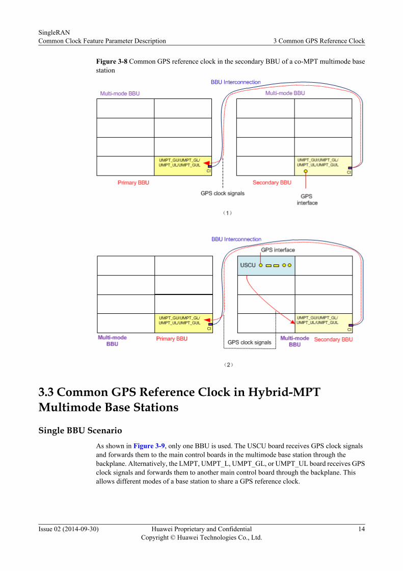
Figure 3-8 Common GPS reference clock in the secondary BBU of a co-MPT multimode basestation
3.3 Common GPS Reference Clock in Hybrid-MPTMultimode Base Stations
Single BBU ScenarioAs shown in Figure 3-9, only one BBU is used. The USCU board receives GPS clock signalsand forwards them to the main control boards in the multimode base station through thebackplane. Alternatively, the LMPT, UMPT_L, UMPT_GL, or UMPT_UL board receives GPSclock signals and forwards them to another main control board through the backplane. Thisallows different modes of a base station to share a GPS reference clock.
SingleRANCommon Clock Feature Parameter Description 3 Common GPS Reference Clock
Issue 02 (2014-09-30) Huawei Proprietary and ConfidentialCopyright © Huawei Technologies Co., Ltd.
14

Figure 3-9 Common GPS reference clock in a hybrid-MPT triple-mode base station
BBU Interconnection ScenarioThe common GPS reference clock sharing in BBU interconnection scenarios where the separate-MPT base station and co-MPT base station coexist is similar to that in BBU interconnection
SingleRANCommon Clock Feature Parameter Description 3 Common GPS Reference Clock
Issue 02 (2014-09-30) Huawei Proprietary and ConfidentialCopyright © Huawei Technologies Co., Ltd.
15

scenarios of separate-MPT base stations. For details, see BBU Interconnection Scenario insection 3.1 Common GPS Reference Clock in Separate-MPT Multimode Base Stations.
SingleRANCommon Clock Feature Parameter Description 3 Common GPS Reference Clock
Issue 02 (2014-09-30) Huawei Proprietary and ConfidentialCopyright © Huawei Technologies Co., Ltd.
16

4 Common BITS Reference Clock
This chapter describes the common BITS reference clock in separate-MPT, co-MPT, and hybrid-MPT multimode base stations. The BITS reference clock only supports frequencysynchronization, and does not support time synchronization. The LTE mode and eNodeBmentioned in this chapter refer to FDD.
SingleRANCommon Clock Feature Parameter Description 4 Common BITS Reference Clock
Issue 02 (2014-09-30) Huawei Proprietary and ConfidentialCopyright © Huawei Technologies Co., Ltd.
17

4.1 Common BITS Reference Clock in Separate-MPTMultimode Base Stations
Single BBU ScenarioAs shown in Figure 4-1, Figure 4-2, and Figure 4-3, the USCU board in a dual-mode basestation receives BITS clock signals and forwards them to the two main control boards in thebase station.
Figure 4-1 Common BITS reference clock in a separate-MPT GSM/UMTS dual-mode basestation
Figure 4-2 Common BITS reference clock in a separate-MPT GSM/LTE dual-mode base station
SingleRANCommon Clock Feature Parameter Description 4 Common BITS Reference Clock
Issue 02 (2014-09-30) Huawei Proprietary and ConfidentialCopyright © Huawei Technologies Co., Ltd.
18

Figure 4-3 Common BITS reference clock in a separate-MPT UMTS/LTE dual-mode basestation
BBU Interconnection ScenarioThe following uses the BBU interconnection achieved by connecting one UCIU board and oneUMPT board as an example to describe the procedure for sharing the BITS reference clock inseparate-MPT multimode base stationsl As shown in Figure 4-4, the USCU board is installed in the primary BBU of a GSM/UMTS/
LTE triple-mode base station. The USCU board receives BITS clock signals and forwardsthem to the GTMU and LMPT/UMPT_L boards. Upon receiving the clock signals, theGTMU board forwards them to the UCIU board. The UCIU board then sends the clocksignals to the UMPT_U board in the secondary BBU, which receives them through its BBUinterconnection port.
l As shown in Figure 4-5, the USCU board is installed in the secondary BBU of a GSM/UMTS/LTE triple-mode base station. The USCU board receives BITS clock signals andforwards them to the UMPT_U board, which in turn sends them through its BBUinterconnection port to the UCIU board in the primary BBU. The UCIU board then sendsthe clock signals to the GTMU and LMPT/UMPT_L boards through the backplane.
SingleRANCommon Clock Feature Parameter Description 4 Common BITS Reference Clock
Issue 02 (2014-09-30) Huawei Proprietary and ConfidentialCopyright © Huawei Technologies Co., Ltd.
19
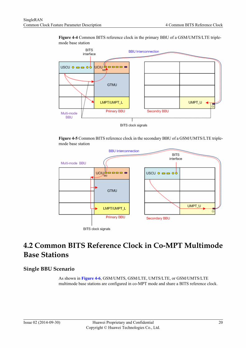
Figure 4-4 Common BITS reference clock in the primary BBU of a GSM/UMTS/LTE triple-mode base station
Figure 4-5 Common BITS reference clock in the secondary BBU of a GSM/UMTS/LTE triple-mode base station
4.2 Common BITS Reference Clock in Co-MPT MultimodeBase Stations
Single BBU ScenarioAs shown in Figure 4-6, GSM/UMTS, GSM/LTE, UMTS/LTE, or GSM/UMTS/LTEmultimode base stations are configured in co-MPT mode and share a BITS reference clock.
SingleRANCommon Clock Feature Parameter Description 4 Common BITS Reference Clock
Issue 02 (2014-09-30) Huawei Proprietary and ConfidentialCopyright © Huawei Technologies Co., Ltd.
20

Figure 4-6 Common BITS reference clock in a co-MPT multimode base station
BBU Interconnection Scenario
The following uses the BBU interconnection achieved by connecting two UMPT boards as anexample to describe the procedure for sharing the BITS reference clock in co-MPT multimodebase stations.
l As shown in Figure 4-7, the BITS reference clock is located in the primary BBU of a co-MPT multimode base station and the USCU board in the primary BBU receives the BITSclock signals. In this case, the USCU board in the primary BBU receives BITS clock signalsand forwards them to the UMPT board in the primary BBU through the backplane. Uponreceiving the clock signals, the UMPT board forwards them to the UMPT board in thesecondary BBU through the BBU interconnection port.
l As shown in Figure 4-8, the BITS clock is located in the secondary BBU of a co-MPTmultimode base station and the USCU boards in the secondary BBU can receive BITSclock signals. In this case, the USCU board in the secondary BBU receives BITS clocksignals and forwards them to the UMPT board in the secondary BBU through the backplane.Upon receiving the clock signals, the UMPT board forwards them to the UMPT board inthe primary BBU through the BBU interconnection port.
Figure 4-7 Common BITS reference clock in the primary BBU of a co-MPT multimode basestation
SingleRANCommon Clock Feature Parameter Description 4 Common BITS Reference Clock
Issue 02 (2014-09-30) Huawei Proprietary and ConfidentialCopyright © Huawei Technologies Co., Ltd.
21
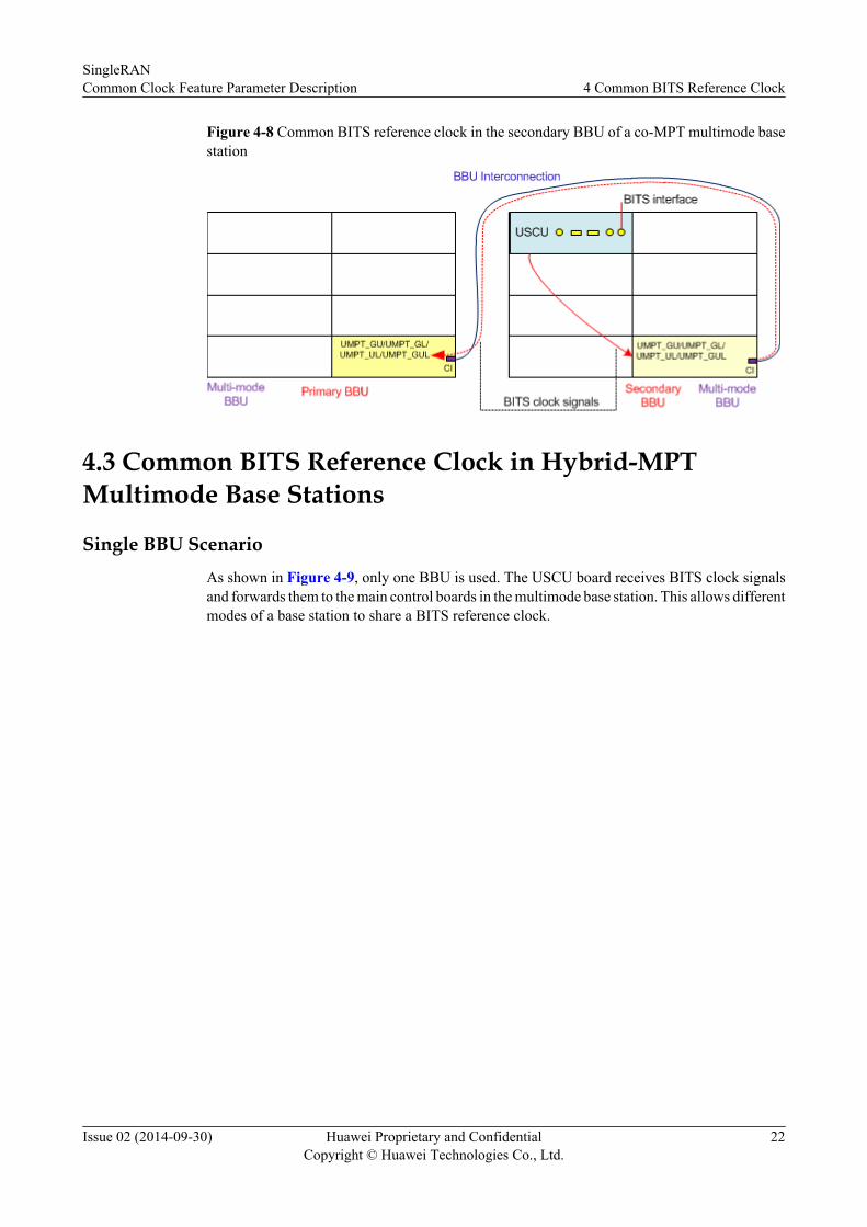
Figure 4-8 Common BITS reference clock in the secondary BBU of a co-MPT multimode basestation
4.3 Common BITS Reference Clock in Hybrid-MPTMultimode Base Stations
Single BBU ScenarioAs shown in Figure 4-9, only one BBU is used. The USCU board receives BITS clock signalsand forwards them to the main control boards in the multimode base station. This allows differentmodes of a base station to share a BITS reference clock.
SingleRANCommon Clock Feature Parameter Description 4 Common BITS Reference Clock
Issue 02 (2014-09-30) Huawei Proprietary and ConfidentialCopyright © Huawei Technologies Co., Ltd.
22

Figure 4-9 Common BITS reference clock in a hybrid-MPT triple-mode base station
BBU Interconnection ScenarioThe common BITS reference clock sharing in BBU interconnection scenarios where theseparate-MPT base station and co-MPT base station coexist is similar to that in BBUinterconnection scenarios of separate-MPT base stations. For details, see BBU InterconnectionScenario in section 4.1 Common BITS Reference Clock in Separate-MPT Multimode BaseStations.
SingleRANCommon Clock Feature Parameter Description 4 Common BITS Reference Clock
Issue 02 (2014-09-30) Huawei Proprietary and ConfidentialCopyright © Huawei Technologies Co., Ltd.
23
5 Common E1/T1 Reference Clock
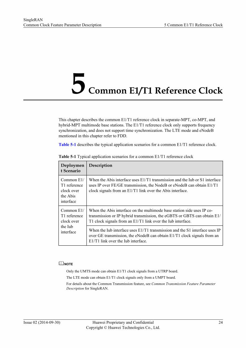
This chapter describes the common E1/T1 reference clock in separate-MPT, co-MPT, andhybrid-MPT multimode base stations. The E1/T1 reference clock only supports frequencysynchronization, and does not support time synchronization. The LTE mode and eNodeBmentioned in this chapter refer to FDD.
Table 5-1 describes the typical application scenarios for a common E1/T1 reference clock.
Table 5-1 Typical application scenarios for a common E1/T1 reference clock
Deployment Scenario
Description
Common E1/T1 referenceclock overthe Abisinterface
When the Abis interface uses E1/T1 transmission and the Iub or S1 interfaceuses IP over FE/GE transmission, the NodeB or eNodeB can obtain E1/T1clock signals from an E1/T1 link over the Abis interface.
Common E1/T1 referenceclock overthe Iubinterface
When the Abis interface on the multimode base station side uses IP co-transmission or IP hybrid transmission, the eGBTS or GBTS can obtain E1/T1 clock signals from an E1/T1 link over the Iub interface.
When the Iub interface uses E1/T1 transmission and the S1 interface uses IPover GE transmission, the eNodeB can obtain E1/T1 clock signals from anE1/T1 link over the Iub interface.
NOTE
Only the UMTS mode can obtain E1/T1 clock signals from a UTRP board.
The LTE mode can obtain E1/T1 clock signals only from a UMPT board.
For details about the Common Transmission feature, see Common Transmission Feature ParameterDescription for SingleRAN.
SingleRANCommon Clock Feature Parameter Description 5 Common E1/T1 Reference Clock
Issue 02 (2014-09-30) Huawei Proprietary and ConfidentialCopyright © Huawei Technologies Co., Ltd.
24

5.1 Common E1/T1 Reference Clock in Separate-MPTMultimode Base Stations
Single BBU ScenarioAs shown in Figure 5-1, Figure 5-2, and Figure 5-3, one mode of a multimode base station isconfigured with an E1/T1 clock source, and then the other modes share E1/T1 clock signals byusing the BBU backplane.
Figure 5-1 Common E1/T1 reference clock in a separate-MPT GSM/UMTS dual-mode basestation
SingleRANCommon Clock Feature Parameter Description 5 Common E1/T1 Reference Clock
Issue 02 (2014-09-30) Huawei Proprietary and ConfidentialCopyright © Huawei Technologies Co., Ltd.
25

Figure 5-2 Common E1/T1 reference clock in a separate-MPT GSM/LTE dual-mode basestation
Figure 5-3 Common E1/T1 reference clock in a separate-MPT UMTS/LTE dual-mode basestation
BBU Interconnection ScenarioThe following uses the BBU interconnection achieved by connecting one UCIU board and oneUMPT board as an example. When BBU Interconnection is enabled, one mode of a GSM/UMTS/LTE triple-mode base station is configured with an E1/T1 clock source and the other two modesshare the E1/T1 clock source. The procedure for sharing the E1/T1 clock source is as follows:l As shown in Figure 5-4, the common E1/T1 reference clock is in the primary BBU of a
GSM/UMTS/LTE triple-mode base station. The GTMU board receives E1/T1 clock signals
SingleRANCommon Clock Feature Parameter Description 5 Common E1/T1 Reference Clock
Issue 02 (2014-09-30) Huawei Proprietary and ConfidentialCopyright © Huawei Technologies Co., Ltd.
26

from the transport network over an E1/T1 link and forwards them to the LMPT and UCIUboards. Upon receiving the clock signals, the UCIU board sends them to the UMPT boardin the secondary BBU, which receives them over the BBU interconnection port.
l As shown in Figure 5-5, the common E1/T1 reference clock is in the secondary BBU of aGSM/UMTS/LTE triple-mode base station. The UMPT board receives E1/T1 clock signalsfrom the transport network over an E1/T1 link and forwards them to the UCIU board in theprimary BBU. Upon receiving the clock signals, the UCIU board sends them to the GTMUand LMPT boards by using the BBU backplane.
Figure 5-4 Common E1/T1 reference clock in the primary BBU of a GSM/UMTS/LTE triple-mode base station
Figure 5-5 Common E1/T1 reference clock in the secondary BBU of a GSM/UMTS/LTE triple-mode base station
SingleRANCommon Clock Feature Parameter Description 5 Common E1/T1 Reference Clock
Issue 02 (2014-09-30) Huawei Proprietary and ConfidentialCopyright © Huawei Technologies Co., Ltd.
27
5.2 Common E1/T1 Reference Clock in Co-MPT MultimodeBase Stations
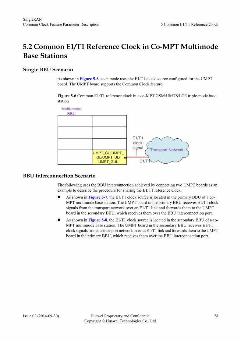
Single BBU ScenarioAs shown in Figure 5-6, each mode uses the E1/T1 clock source configured for the UMPTboard. The UMPT board supports the Common Clock feature.
Figure 5-6 Common E1/T1 reference clock in a co-MPT GSM/UMTS/LTE triple-mode basestation
BBU Interconnection ScenarioThe following uses the BBU interconnection achieved by connecting two UMPT boards as anexample to describe the procedure for sharing the E1/T1 reference clock.l As shown in Figure 5-7, the E1/T1 clock source is located in the primary BBU of a co-
MPT multimode base station. The UMPT board in the primary BBU receives E1/T1 clocksignals from the transport network over an E1/T1 link and forwards them to the UMPTboard in the secondary BBU, which receives them over the BBU interconnection port.
l As shown in Figure 5-8, the E1/T1 clock source is located in the secondary BBU of a co-MPT multimode base station. The UMPT board in the secondary BBU receives E1/T1clock signals from the transport network over an E1/T1 link and forwards them to the UMPTboard in the primary BBU, which receives them over the BBU interconnection port.
SingleRANCommon Clock Feature Parameter Description 5 Common E1/T1 Reference Clock
Issue 02 (2014-09-30) Huawei Proprietary and ConfidentialCopyright © Huawei Technologies Co., Ltd.
28

Figure 5-7 Common E1/T1 reference clock in the primary BBU of a co-MPT multimode basestation
Figure 5-8 Common E1/T1 reference clock in the secondary BBU of a co-MPT multimode basestation
SingleRANCommon Clock Feature Parameter Description 5 Common E1/T1 Reference Clock
Issue 02 (2014-09-30) Huawei Proprietary and ConfidentialCopyright © Huawei Technologies Co., Ltd.
29

5.3 Common E1/T1 Reference Clock in Hybrid-MPTMultimode Base Stations
Single BBU ScenarioAs shown in Figure 5-9, only one BBU is used. Different modes of base stations can share anE1/T1 clock source by using the BBU backplane.
SingleRANCommon Clock Feature Parameter Description 5 Common E1/T1 Reference Clock
Issue 02 (2014-09-30) Huawei Proprietary and ConfidentialCopyright © Huawei Technologies Co., Ltd.
30

Figure 5-9 Common E1/T1 reference clock in a hybrid-MPT GSM/UMTS/LTE triple-modebase station
BBU Interconnection ScenarioThe common E1/T1 reference clock sharing in BBU interconnection scenarios where theseparate-MPT base station and co-MPT base station coexist is similar to that in BBU
SingleRANCommon Clock Feature Parameter Description 5 Common E1/T1 Reference Clock
Issue 02 (2014-09-30) Huawei Proprietary and ConfidentialCopyright © Huawei Technologies Co., Ltd.
31

interconnection scenarios of separate-MPT base stations. For details, see BBU InterconnectionScenario in section 5.1 Common E1/T1 Reference Clock in Separate-MPT Multimode BaseStations.
SingleRANCommon Clock Feature Parameter Description 5 Common E1/T1 Reference Clock
Issue 02 (2014-09-30) Huawei Proprietary and ConfidentialCopyright © Huawei Technologies Co., Ltd.
32

6 Common IEEE 1588v2 Reference Clock
This chapter describes the common IEEE 1588v2 reference clock in separate-MPT, co-MPT,and hybrid-MPT multimode base stations.
Table 6-1 describes the typical application scenarios for a common IEEE 1588v2 referenceclock.
Table 6-1 Typical application scenarios for a common IEEE 1588v2 reference clock
Deployment Scenario Description
Common IEEE 1588v2 reference clock overthe Iub interface
When the Abis and Iub interfaces use IPtransmission and the NodeB of a multimodebase station is configured with an IEEE1588v2 clock source, the BTS can obtainclock signals from the WMPT or UMPTboard in the NodeB by using the BBUbackplane.
When the Iub and S1 interfaces use IPtransmission and the NodeB of a multimodebase station is configured with an IEEE1588v2 clock source, the eNodeB can obtainclock signals from the WMPT or UMPTboard in the NodeB by using the BBUbackplane.
Common IEEE 1588v2 reference clock overthe S1 interface
When the Abis or Iub interface and the S1interface use the IP transmission and theeNodeB of a multimode base station isconfigured with an IEEE 1588v2 clocksource, the GBTS, eGBTS, or NodeB canobtain clock signals from the LMPT orUMPT board in the eNodeB by using theBBU backplane.
SingleRANCommon Clock Feature Parameter Description 6 Common IEEE 1588v2 Reference Clock
Issue 02 (2014-09-30) Huawei Proprietary and ConfidentialCopyright © Huawei Technologies Co., Ltd.
33
Deployment Scenario Description
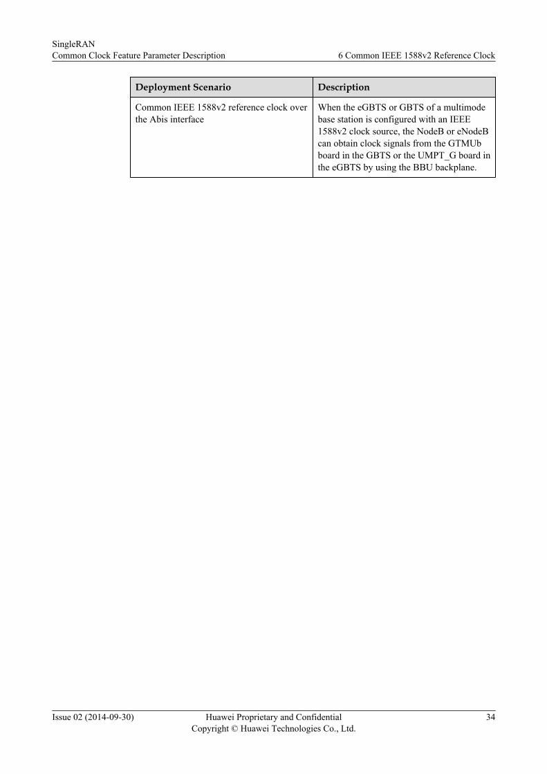
Common IEEE 1588v2 reference clock overthe Abis interface
When the eGBTS or GBTS of a multimodebase station is configured with an IEEE1588v2 clock source, the NodeB or eNodeBcan obtain clock signals from the GTMUbboard in the GBTS or the UMPT_G board inthe eGBTS by using the BBU backplane.
SingleRANCommon Clock Feature Parameter Description 6 Common IEEE 1588v2 Reference Clock
Issue 02 (2014-09-30) Huawei Proprietary and ConfidentialCopyright © Huawei Technologies Co., Ltd.
34

6.1 Common IEEE 1588v2 Reference Clock in Separate-MPTMultimode Base Stations
When the IEEE1588v2 reference clock is used as a frequency synchronization source, LTE TDDuses time synchronization and shares the IEEE 1588v2 reference clock to other modes, whereasother modes cannot share the IEEE 1588v2 reference clock to LTE TDD. This is because LTETDD supports only time synchronization. If other modes share the IEEE 1588v2 reference clockto LTE TDD, the reference clock can use only frequency synchronization.
Single BBU Scenario
As shown in Figure 6-1, Figure 6-2, Figure 6-3, one main control board serving a mode isconnected to the transport network using an FE/GE port. The board is configured with an IEEE1588v2 clock client to obtain clock signals from an IEEE 1588v2 clock server. The oscillatorin the board synchronizes clock signals with the IEEE 1588v2 clock server and transmits thesynchronized 1 pulse per second (PPS) clock signals to the other main control board servinganother mode. In this case, only one IEEE 1588v2 clock client is required. FE stands for fastEthernet and GE stands for gigabit Ethernet.
Figure 6-1 Common IEEE 1588v2 reference clock in a separate-MPT GSM/UMTS dual-modebase station
SingleRANCommon Clock Feature Parameter Description 6 Common IEEE 1588v2 Reference Clock
Issue 02 (2014-09-30) Huawei Proprietary and ConfidentialCopyright © Huawei Technologies Co., Ltd.
35

Figure 6-2 Common IEEE 1588v2 reference clock in a separate-MPT GSM/LTE dual-modebase station
Figure 6-3 Common IEEE 1588v2 reference clock in a separate-MPT UMTS/LTE dual-modebase station
BBU Interconnection ScenarioThe following uses the BBU interconnection achieved by connecting one UCIU board and oneUMPT board as an example. When BBU Interconnection is enabled, one mode of a GSM/UMTS/LTE triple-mode base station is configured with an IEEE 1588v2 clock source and the other two
SingleRANCommon Clock Feature Parameter Description 6 Common IEEE 1588v2 Reference Clock
Issue 02 (2014-09-30) Huawei Proprietary and ConfidentialCopyright © Huawei Technologies Co., Ltd.
36

modes share the IEEE 1588v2 clock source. The procedure for sharing the IEEE 1588v2 clocksource is as follows:
l As shown in Figure 6-4, the common IEEE 1588v2 reference clock is in the primary BBUof a GSM/UMTS/LTE triple-mode base station. The LMPT board is configured with anIEEE 1588v2 clock client and receives IEEE 1588v2 clock packets containing clock signalsfrom an IEEE 1588v2 clock server through the transport network. Then, the LMPT boardgenerates synchronized 1 PPS clock signals and forwards them to the GTMU and UCIUboards. Upon receiving the synchronized 1 PPS clock signals, the UCIU board sends themto the UMPT board in the secondary BBU. Base stations of other modes in the primaryBBU obtain 1 PPS clock signals by using the BBU backplane.
l As shown in Figure 6-5, the common IEEE 1588v2 reference clock is in the secondaryBBU of a GSM/UMTS/LTE triple-mode base station. The UMPT board is configured withan IEEE 1588v2 clock client and receives IEEE 1588v2 clock packets containing clocksignals from an IEEE 1588v2 clock server through the transport network. Then, the UMPTboard generates synchronized 1 PPS clock signals and forwards them to the UCIU boardin the primary BBU, which in turn forwards them to the GTMU and WMPT boards.
Transmission port cabling on a multimode base station and the cabling of a common IEEE1588v2 reference clock are independently deployed. Therefore, the operation of the multimodebase station is not affected.
Figure 6-4 Common IEEE 1588v2 reference clock in the primary BBU of a GSM/UMTS/LTEtriple-mode base station
SingleRANCommon Clock Feature Parameter Description 6 Common IEEE 1588v2 Reference Clock
Issue 02 (2014-09-30) Huawei Proprietary and ConfidentialCopyright © Huawei Technologies Co., Ltd.
37

Figure 6-5 Common IEEE 1588v2 reference clock in the secondary BBU of a GSM/UMTS/LTE triple-mode base station
6.2 Common IEEE 1588v2 Reference Clock in Co-MPTMultimode Base Stations
Single BBU ScenarioAs shown in Figure 6-6, each mode uses the IEEE 1588v2 clock source configured for theUMPT board. The UMPT board supports the Common Clock feature. The shared IEEE 1588v2reference clock supports frequency synchronization and time synchronization. If the LTE TDDmode is used, the clock source must use time synchronization.
Figure 6-6 Common IEEE 1588v2 reference clock in a co-MPT GSM/UMTS/LTE triple-modebase station
SingleRANCommon Clock Feature Parameter Description 6 Common IEEE 1588v2 Reference Clock
Issue 02 (2014-09-30) Huawei Proprietary and ConfidentialCopyright © Huawei Technologies Co., Ltd.
38

BBU Interconnection ScenarioThe following uses the BBU interconnection achieved by connecting two UMPT boards as anexample to describe the procedure for sharing the IEEE 1588v2 reference clock.
l As shown in Figure 6-7, the common IEEE 1588v2 reference clock is in the primary BBUof a co-MPT multimode base station. The UMPT board in the primary BBU is configuredwith an IEEE 1588v2 clock client and receives IEEE 1588v2 clock packets containing clocksignals from an IEEE 1588v2 clock server through the transport network. Then the UMPTboard generates synchronized 1 PPS clock signals and forwards them to the UMPT boardin the secondary BBU through the BBU interconnection port.
l As shown in Figure 6-8, the common IEEE 1588v2 reference clock is in the secondaryBBU of a co-MPT multimode base station. The UMPT board in the secondary BBU isconfigured with an IEEE 1588v2 clock client and receives IEEE 1588v2 clock packetscontaining clock signals from an IEEE 1588v2 clock server through the transport network.Then the UMPT board generates synchronized 1 PPS clock signals and forwards them tothe UMPT board in the primary BBU through the BBU interconnection port.
Figure 6-7 Common IEEE 1588v2 reference clock in the primary BBU of a co-MPT multimodebase station
SingleRANCommon Clock Feature Parameter Description 6 Common IEEE 1588v2 Reference Clock
Issue 02 (2014-09-30) Huawei Proprietary and ConfidentialCopyright © Huawei Technologies Co., Ltd.
39
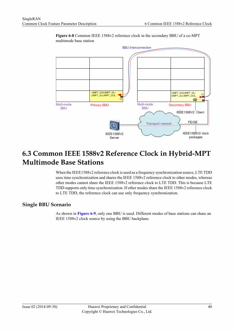
Figure 6-8 Common IEEE 1588v2 reference clock in the secondary BBU of a co-MPTmultimode base station
6.3 Common IEEE 1588v2 Reference Clock in Hybrid-MPTMultimode Base Stations
When the IEEE1588v2 reference clock is used as a frequency synchronization source, LTE TDDuses time synchronization and shares the IEEE 1588v2 reference clock to other modes, whereasother modes cannot share the IEEE 1588v2 reference clock to LTE TDD. This is because LTETDD supports only time synchronization. If other modes share the IEEE 1588v2 reference clockto LTE TDD, the reference clock can use only frequency synchronization.
Single BBU ScenarioAs shown in Figure 6-9, only one BBU is used. Different modes of base stations can share anIEEE 1588v2 clock source by using the BBU backplane.
SingleRANCommon Clock Feature Parameter Description 6 Common IEEE 1588v2 Reference Clock
Issue 02 (2014-09-30) Huawei Proprietary and ConfidentialCopyright © Huawei Technologies Co., Ltd.
40

Figure 6-9 Common IEEE 1588v2 reference clock in a hybrid-MPT GSM/UMTS/LTE triple-mode base station
SingleRANCommon Clock Feature Parameter Description 6 Common IEEE 1588v2 Reference Clock
Issue 02 (2014-09-30) Huawei Proprietary and ConfidentialCopyright © Huawei Technologies Co., Ltd.
41

BBU Interconnection ScenarioThe common IEEE 1588v2 reference clock sharing in BBU interconnection scenarios where theseparate-MPT base station and co-MPT base station coexist is similar to that in BBUinterconnection scenarios of separate-MPT base stations. For details, see BBU InterconnectionScenario in section 6.1 Common IEEE 1588v2 Reference Clock in Separate-MPTMultimode Base Stations.
SingleRANCommon Clock Feature Parameter Description 6 Common IEEE 1588v2 Reference Clock
Issue 02 (2014-09-30) Huawei Proprietary and ConfidentialCopyright © Huawei Technologies Co., Ltd.
42

7 Common Synchronous Ethernet ReferenceClock
This chapter describes the common synchronous Ethernet reference clock in separate-MPT, co-MPT, and hybrid-MPT multimode base stations. The synchronous Ethernet reference clock onlysupports frequency synchronization, and does not support time synchronization. The LTE modeand eNodeB mentioned in this chapter refer to FDD.
Table 7-1 describes the typical application scenarios for a common synchronous Ethernetreference clock.
Table 7-1 Typical application scenarios for a common synchronous Ethernet reference clock
Deployment Scenario
Description
CommonsynchronousEthernetreferenceclock overthe Iubinterface
When the Iub interface on the multimode base station side uses IP transmissionand the IP network supports Ethernet clock synchronization, the eGBTS,GBTS, or eNodeB can obtain clock signals from the WMPT, UMPT, UTRPboard in the NodeB by using the BBU backplane. The UTRP board is managedby the UMTS mode and supports FE/GE transmission.
CommonsynchronousEthernetreferenceclock overthe S1interface
When the S1 interface uses IP transmission and the IP network supportsEthernet clock synchronization, the eGBTS, GBTS, or NodeB can obtainclock signals from the LMPT, UMPT, UTRP board in the eNodeB by usingthe BBU backplane. The UTRP board is managed by the LTE mode andsupports FE/GE transmission.
SingleRANCommon Clock Feature Parameter Description 7 Common Synchronous Ethernet Reference Clock
Issue 02 (2014-09-30) Huawei Proprietary and ConfidentialCopyright © Huawei Technologies Co., Ltd.
43

Deployment Scenario
Description
CommonsynchronousEthernetreferenceclock overthe Abisinterface
When the eGBTS or GBTS of a multimode base station is configured with asynchronous Ethernet clock source, the NodeB or eNodeB can obtain clocksignals by using the BBU backplane from any of the following boards:l UMPT or UTRP board in the eGBTSl GTMUb or UTRP board in the GBTSThe UTRP board is managed by the GSM mode and supports FE/GEtransmission.
SingleRANCommon Clock Feature Parameter Description 7 Common Synchronous Ethernet Reference Clock
Issue 02 (2014-09-30) Huawei Proprietary and ConfidentialCopyright © Huawei Technologies Co., Ltd.
44

7.1 Common Synchronous Ethernet Reference Clock inSeparate-MPT Multimode Base Stations
Single BBU ScenarioAs shown in Figure 7-1, Figure 7-2, Figure 7-3, to implement a common synchronous Ethernetreference clock, one mode of a dual-mode base station must connect to the transport networkover its FE/GE port and the IP network must support Ethernet clock synchronization. Thisensures that the other mode of the base station can receive synchronous Ethernet clock signalsby using the BBU backplane.
Figure 7-1 Common synchronous Ethernet reference clock in a separate-MPT GSM/UMTSdual-mode base station
SingleRANCommon Clock Feature Parameter Description 7 Common Synchronous Ethernet Reference Clock
Issue 02 (2014-09-30) Huawei Proprietary and ConfidentialCopyright © Huawei Technologies Co., Ltd.
45

Figure 7-2 Common synchronous Ethernet reference clock in a separate-MPT GSM/LTE dual-mode base station
Figure 7-3 Common synchronous Ethernet reference clock in a separate-MPT UMTS/LTE dual-mode base station
BBU Interconnection ScenarioThe following uses the BBU interconnection achieved by connecting one UCIU board and oneUMPT board as an example. When BBU Interconnection is enabled, one mode of a separate-MPT multimode base station is configured with a synchronous Ethernet clock source and theother two modes share the synchronous Ethernet clock source. The procedure for sharing thesynchronous Ethernet clock source is as follows:
SingleRANCommon Clock Feature Parameter Description 7 Common Synchronous Ethernet Reference Clock
Issue 02 (2014-09-30) Huawei Proprietary and ConfidentialCopyright © Huawei Technologies Co., Ltd.
46

l As shown in Figure 7-4, the common synchronous Ethernet reference clock in the primaryBBU of a GSM/UMTS/LTE triple-mode base station. The WMPT board receivessynchronous Ethernet clock signals from the transport network over an FE link andforwards them to the GTMU and UCIU boards. Upon receiving the clock signals, the UCIUboard sends them to the UMPT board in the secondary BBU. The other mode of base stationin the primary BBU obtains synchronous Ethernet clock signals by using the BBUbackplane.
l As shown in Figure 7-5, the common synchronous Ethernet reference clock in thesecondary BBU of a GSM/UMTS/LTE triple-mode base station. The UMPT board receivessynchronous Ethernet clock signals from the transport network over a GE link and forwardsthem to the UCIU board in the primary BBU. Upon receiving the clock signals, the UCIUboard sends them to the GTMU and WMPT boards.
Figure 7-4 Common synchronous Ethernet reference clock in the primary BBU of a GSM/UMTS/LTE triple-mode base station
SingleRANCommon Clock Feature Parameter Description 7 Common Synchronous Ethernet Reference Clock
Issue 02 (2014-09-30) Huawei Proprietary and ConfidentialCopyright © Huawei Technologies Co., Ltd.
47

Figure 7-5 Common synchronous Ethernet reference clock in the secondary BBU of a GSM/UMTS/LTE triple-mode base station
7.2 Common Synchronous Ethernet Reference Clock in Co-MPT Multimode Base Stations
Single BBU Scenario
As shown in Figure 7-6, each mode uses the synchronous Ethernet clock source configured forthe UMPT board. The UMPT board supports the Common Clock feature.
Figure 7-6 Common synchronous Ethernet reference clock in a co-MPT GSM/UMTS/LTEtriple-mode base station
BBU Interconnection Scenario
The following uses the BBU interconnection achieved by connecting two UMPT boards as anexample to describe the procedure for sharing the synchronous Ethernet reference clock.
SingleRANCommon Clock Feature Parameter Description 7 Common Synchronous Ethernet Reference Clock
Issue 02 (2014-09-30) Huawei Proprietary and ConfidentialCopyright © Huawei Technologies Co., Ltd.
48

l As shown in Figure 7-7, the common synchronous Ethernet reference clock in the primaryBBU of a co-MPT multimode base station. The UMPT board in the primary BBU receivessynchronous Ethernet clock signals from the transport network over an FE link andforwards them to the UMPT board in the secondary BBU through the BBU interconnectionport.
l As shown in Figure 7-8, the common synchronous Ethernet reference clock in thesecondary BBU of a co-MPT multimode base station. The UMPT board in the secondaryBBU receives synchronous Ethernet clock signals from the transport network over an FElink and forwards them to the UMPT board in the primary BBU through the BBUinterconnection port.
Figure 7-7 Common synchronous Ethernet reference clock in the primary BBU of a co-MPTmultimode base station
SingleRANCommon Clock Feature Parameter Description 7 Common Synchronous Ethernet Reference Clock
Issue 02 (2014-09-30) Huawei Proprietary and ConfidentialCopyright © Huawei Technologies Co., Ltd.
49

Figure 7-8 Common synchronous Ethernet reference clock in the secondary BBU of a co-MPTmultimode base station
7.3 Common Synchronous Ethernet Reference Clock inHybrid-MPT Multimode Base Stations
Single BBU ScenarioAs shown in Figure 7-9, only one BBU is used. Different modes of base stations can share asynchronous Ethernet clock source by using the BBU backplane.
SingleRANCommon Clock Feature Parameter Description 7 Common Synchronous Ethernet Reference Clock
Issue 02 (2014-09-30) Huawei Proprietary and ConfidentialCopyright © Huawei Technologies Co., Ltd.
50

Figure 7-9 Common synchronous Ethernet reference clock in a hybrid-MPT GSM/UMTS/LTEtriple-mode base station
SingleRANCommon Clock Feature Parameter Description 7 Common Synchronous Ethernet Reference Clock
Issue 02 (2014-09-30) Huawei Proprietary and ConfidentialCopyright © Huawei Technologies Co., Ltd.
51

BBU Interconnection ScenarioThe common synchronous Ethernet reference clock sharing in BBU interconnection scenarioswhere the separate-MPT base station and co-MPT base station coexist is similar to that in BBUinterconnection scenarios of separate-MPT base stations. For details, see BBU InterconnectionScenario in section 7.1 Common Synchronous Ethernet Reference Clock in Separate-MPTMultimode Base Stations.
SingleRANCommon Clock Feature Parameter Description 7 Common Synchronous Ethernet Reference Clock
Issue 02 (2014-09-30) Huawei Proprietary and ConfidentialCopyright © Huawei Technologies Co., Ltd.
52

8 Other Common Reference Clocks
When the GSM, UMTS, and LTE modes share a UMTS board, besides common GPS, BITS,E1/T1, IEEE 1588v2, and synchronous Ethernet reference clocks, the following commonreference clocks can be used:
l Common 1PPS+TOD reference clockl Common IEEE 1588v2+SyncE reference clock
These two common reference clocks are used only when the GSM, UMTS, and LTE modesshare a UMPT board. This is because these two common reference clocks only support a singlemode in a separate-MPT multimode base station.
SingleRANCommon Clock Feature Parameter Description 8 Other Common Reference Clocks
Issue 02 (2014-09-30) Huawei Proprietary and ConfidentialCopyright © Huawei Technologies Co., Ltd.
53

8.1 Common 1PPS+TOD Reference Clock in Co-MPT GSM/UMTS/LTE Triple-mode Base Stations
The 1PPS+TOD clock source supports frequency synchronization and time synchronization. Asshown in Figure 8-1, the USCU and UMPT boards can receive 1PPS+TOD clock signals. TheUMPT board is configured with the 1PPS+TOD clock source, which is shared by the GSM,UMTS, and LTE modes.
Figure 8-1 A common 1PPS+TOD reference clock in a co-MPT GSM/UMTS/LTE triple-modebase station
8.2 Common IEEE 1588v2+SyncE Reference Clock in Co-MPT GSM/UMTS/LTE Triple-mode Base Stations
The IEEE 1588v2+SyncE clock source combines the IEEE 1588v2 clock and synchronousEthernet clock and supports only time synchronization. The clock source of the IEEE 1588v2clock server must be the same as that of the synchronous Ethernet. As shown in Figure 8-2, theUMPT board is configured with the IEEE 1588v2+SyncE clock source, which is shared by theGSM, UMTS, and LTE modes. The clock source of the IEEE 1588v2 clock server and thesynchronous Ethernet in Figure 8-2 are GPS.
SingleRANCommon Clock Feature Parameter Description 8 Other Common Reference Clocks
Issue 02 (2014-09-30) Huawei Proprietary and ConfidentialCopyright © Huawei Technologies Co., Ltd.
54

Figure 8-2 A common IEEE 1588v2+SyncE reference clock in a co-MPT GSM/UMTS/LTE triple-mode base station
SingleRANCommon Clock Feature Parameter Description 8 Other Common Reference Clocks
Issue 02 (2014-09-30) Huawei Proprietary and ConfidentialCopyright © Huawei Technologies Co., Ltd.
55

9 Engineering Guidelines
9.1 When to Use Common ClockIt is recommended that MRFD-211601 Multi-mode BS Common Reference Clock(GBTS/eGBTS), MRFD-221601 Multi-mode BS Common Reference Clock(NodeB), orMRFD-231601 Multi-mode BS Common Reference Clock (eNodeB) be enabled for amultimode base station to reduce the OPEX and CAPEX.
9.2 Required InformationThe information to be collected is as follows:
l Whether the multimode base station using the LTE TDD mode is configured with a GPSantennaIf the multimode base station is configured with a GPS antenna, it is recommended that allmodes of the base station share a GPS reference clock.
l Transmission scheme used by the multimode base station that does not use the LTE TDDmode– If at least one mode of the multimode base station uses E1/T1 transmission, use a
common E1/T1 reference clock.– If all modes of the multimode base station use FE/GE transmission, check whether
synchronous Ethernet is supported. If yes, use a common synchronous Ethernetreference clock. If no, use a common IEEE 1588v2 reference clock.
9.3 RequirementsMRFD-211601 Multi-mode BS Common Reference Clock(GBTS/eGBTS), MRFD-221601Multi-mode BS Common Reference Clock(NodeB), MRFD-231601 Multi-mode BS CommonReference Clock(eNodeB), and MRFD-241601 Multi-mode BS Common Reference Clock(LTETDD) are under license control.
MRFD-231601 Multi-mode BS Common Reference Clock(eNodeB) and MRFD-241601 Multi-mode BS Common Reference Clock(LTE TDD) have license control items. The other twofeatures only have license sales items and do not have license control items.
SingleRANCommon Clock Feature Parameter Description 9 Engineering Guidelines
Issue 02 (2014-09-30) Huawei Proprietary and ConfidentialCopyright © Huawei Technologies Co., Ltd.
56

FeatureID
FeatureName
License Control Item NE Sales Unit
MRFD-231601
Multi-mode BSCommonReferenceClock(eNodeB)
Function-LTE-LLT1MCRC01 CommonClock (eNodeB) (pereNodeB)
eNodeB per eNodeB
MRFD-241601
Multi-mode BSCommonReferenceClock(LTETDD)
eNodeB Per eNodeB
The following are the requirements for FDD(TDD):
l The TDD eNodeB can only use the GPS reference clock provided by the GBTS/eGBTSthat uses time synchronization.
l The TDD eNodeB can only use the GPS reference clock provided by the NodeB that usestime synchronization.
l The TDD eNodeB can only use the GPS reference clock provided by the co-MPT basestation that uses time synchronization.
l If the LTE TDD mode is used in a multimode base station, a clock source that supportstime synchronization must be used, for example, GPS reference clock, IEEE 1588v2reference clock, 1PPS+TOD reference clock, or IEEE 1588v2+SyncE reference clock. Inaddition, the clock source must use time synchronization.
Hardwarel This feature applies to GSM/UMTS/LTE multimode base stations that share the same BBU.
l If a BITS reference clock is used, a USCU board must be installed in the BBU.
Other Featuresl Common GPS reference clock
– GBFD-510401 BTS GPS Synchronization
– MRFD-210501 BTS/NodeB Clock
– LBFD-00300504 Synchronization with BITS
– TDLBFD-00300503 Synchronization with GPS
l Common BITS reference clock
– MRFD-210501 BTS/NodeB Clock
– LBFD-00300504 Synchronization with BITS
l Common synchronous Ethernet reference clock
SingleRANCommon Clock Feature Parameter Description 9 Engineering Guidelines
Issue 02 (2014-09-30) Huawei Proprietary and ConfidentialCopyright © Huawei Technologies Co., Ltd.
57

– GBFD-118202 Synchronous Ethernet
– WRFD-050502 Synchronous Ethernet
– LOFD-00301301 Synchronization with Ethernet(ITU-T G.8261)
l Common IEEE 1588v2 reference clock
– MRFD-210501 BTS/NodeB Clock
– WRFD-050501 Clock Sync on Ethernet in NodeB
– LOFD-00301302 IEEE 1588v2 Clock Synchronization
– TDLOFD-00301302 IEEE1588 V2 Clock Synchronization
l Common 1PPS+TOD reference clock
– MRFD-210501 BTS/NodeB Clock
– LBFD-00300505 Synchronization with 1PPS
– TDLBFD-00300505 Synchronization with 1PPS
l Common IEEE 1588v2+SyncE reference clock
– GBFD-118202 Synchronous Ethernet
– WRFD-050502 Synchronous Ethernet
– LOFD-00301302 IEEE 1588v2 Clock Synchronization
– TDLOFD-00301302 IEEE1588 V2 Clock Synchronization
– LOFD-00301301 Synchronization with Ethernet(ITU-T G.8261)
9.4 Initial ConfigurationThis document provides system clock configuration for each of the NEs that share a clock sourceand their common reference clock configuration. For details about how to configure the clocksource of the NE that provides the common reference clock, see Synchronization FeatureParameter Description for the corresponding mode. This section describes how to configure acommon clock in typical application scenarios.
9.4.1 GBTS/eGBTS Providing Clock Source for NodeB/eNodeB/Co-MPT Base Station
The configuration procedure involves configuring the reference clock on the GBTS or eGBTSside and Configuring a Common Reference Clock for NodeB/eNodeB/Co-MPT BaseStation. To configure a reference clock on the GBTS or eGBTS side, refer to one of the followingsections:
l Configuring a Common GPS Reference Clock on the GBTS or eGBTS Side
l Configuring a Common BITS Reference Clock on the GBTS or eGBTS Side
l Configuring a Common E1/T1 Reference Clock on the GBTS or eGBTS Side
l Configuring a Common IEEE 1588v2 Reference Clock on the GBTS or eGBTS Side
l Configuring a Common Synchronous Ethernet Reference Clock on the GBTS oreGBTS Side
SingleRANCommon Clock Feature Parameter Description 9 Engineering Guidelines
Issue 02 (2014-09-30) Huawei Proprietary and ConfidentialCopyright © Huawei Technologies Co., Ltd.
58

Configuring a Common GPS Reference Clock on the GBTS or eGBTS SideBefore configuring a common GPS reference clock, ensure that the GBTS or eGBTS has beenconfigured with a USCU board.
To configure a common GPS reference clock for the GBTS, perform the following steps:
Step 1 Run the SET BTSUSCUBP command to add a GPS clock link.
Step 2 Run the SET BTSCLK command with ClkType (the CME name is Clock Type) set toTRCGPS_CLK(Trace GPS Clock).
----End
To configure a common GPS reference clock for the eGBTS, perform the following steps:
Step 1 Run the ADD GPS command to add a GPS clock link.
Step 2 Run the SET CLKMODE command to activate the GPS reference clock. Set the key parametersaccording to the descriptions in the following table.
Parameter Name MML ParameterID
Parameter Nameon the CME
Setting Notes
System clockworking mode
MODE System ClockWorking Mode
Set this parameter toMANUAL(ManualHandover).
Selected ClockSource
CLKSRC Clock Source Type Set this parameter toGPS(GPS Clock).
----End
Configuring a Common BITS Reference Clock on the GBTS or eGBTS SideBefore configuring a common BITS reference clock, ensure that the GBTS or eGBTS has beenconfigured with a USCU board.
To configure a common BITS reference clock for the GBTS, perform the following step:
Run the SET BTSCLK command with ClkType (the CME name is Clock Type) set toEXTSYN_CLK(External Sync clock).
To configure a common BITS reference clock for the eGBTS, perform the following steps:
Step 1 Run the ADD BITS command to add a BITS clock link.
Step 2 Run the SET CLKMODE command to activate the BITS reference clock. Set the keyparameters according to the descriptions in the following table.
Parameter Name MML ParameterID
Parameter Nameon the CME
Setting Notes
System clockworking mode
MODE System ClockWorking Mode
Set this parameter toMANUAL(ManualHandover).
SingleRANCommon Clock Feature Parameter Description 9 Engineering Guidelines
Issue 02 (2014-09-30) Huawei Proprietary and ConfidentialCopyright © Huawei Technologies Co., Ltd.
59

Parameter Name MML ParameterID
Parameter Nameon the CME
Setting Notes
Selected ClockSource
CLKSRC Clock Source Type Set this parameter toBITS(BITS Clock).
----End
Configuring a Common E1/T1 Reference Clock on the GBTS or eGBTS Side
Before configuring a common E1/T1 reference clock, ensure that an E1/T1 clock link isavailable.
To configure a common E1/T1 reference clock for the GBTS, perform the following step:
Run the SET BTSCLK command with ClkType (the CME name is Clock Type) set toTRCBSC_CLK(Trace BSC Clock).
To configure a common E1/T1 reference clock for the eGBTS, perform the following steps:
Step 1 Run the ADD LINECLK command to add an E1/T1 clock link. In this step, set Port Type(Port Type on the CME) to E1T1(E1T1).
Step 2 Run the SET CLKMODE command to activate the E1/T1 reference clock. Set the keyparameters according to the descriptions in the following table.
Parameter Name MML ParameterID
Parameter Nameon the CME
Setting Notes
System clockworking mode
MODE System ClockWorking Mode
Set this parameter toMANUAL(ManualHandover).
Selected ClockSource
CLKSRC Clock Source Type Set this parameter toLINECLK(LineClock).
----End
Configuring a Common IEEE 1588v2 Reference Clock on the GBTS or eGBTS Side
To configure a common IEEE 1588v2 reference clock for the GBTS, perform the followingsteps:
Step 1 Run the SET BTSCLK command with ClkType (the CME name is Clock Type) set toIP_TIME(IP Clock).
Step 2 Run the SET BTSIPCLKPARA command to configure parameters for an IEEE 1588v2 clocklink. Set the key parameters according to the descriptions in the following table.
SingleRANCommon Clock Feature Parameter Description 9 Engineering Guidelines
Issue 02 (2014-09-30) Huawei Proprietary and ConfidentialCopyright © Huawei Technologies Co., Ltd.
60

ParameterName
MMLParameter ID
ParameterName on theCME
Setting Notes
ClockProtocol Type
CLKPRTTYPE Clock ProtocolType
Set this parameter to PTP(PTP).
IP Clock TimeSynchronization Mode
SYNMode ClockSynchronizationMode
Set this parameter to CONSYN(Consecutive Synchronizing) orINTERSYN(IntermittentSynchronizing).
ClockTopologyMode
CLKTOPOMODE
Clock TopologyMode
Set this parameter toPTPOVERUDP(PTP over UDPUnicast) or PTPOVERMAC(PTP over MAC Multicast).
ClockReferenceSourceRedundancy
ISCLKREDUCY Clock ReferenceSourceRedundancy
Set this parameter toUNSUPPORT(Not SupportReducy) or SUPPORT(SupportReducy).
Clock Server0 IP Address
MASTERIPADDR
Clock Server 0 IPAddress
Set this parameter to the IP addressof clock server 0 on the IP clocklink.
Clock Server1 IP Address
SLAVEIPADDR Clock Server 1 IPAddress
Set this parameter to the IP addressof clock server 1 on the IP clocklink.
----End
To configure a common IEEE 1588v2 reference clock for the eGBTS, perform the followingsteps:
Step 1 Run the ADD IPCLKLINK command to add an IEEE 1588v2 clock link. Set the key parametersaccording to the descriptions in the following table.
ParameterName
MMLParameter ID
ParameterName on theCME
Setting Notes
Protocol Type ICPT Protocol Type Set this parameter to PTP(PTP).
SingleRANCommon Clock Feature Parameter Description 9 Engineering Guidelines
Issue 02 (2014-09-30) Huawei Proprietary and ConfidentialCopyright © Huawei Technologies Co., Ltd.
61

ParameterName
MMLParameter ID
ParameterName on theCME
Setting Notes
Profile Type PROFILETYPE Profile Type Set this parameter to 1588V2, G.8265.1 or 1588V2_16.1.In most cases, set this parameter to1588V2(1588V2). If the IP clockserver is a third-party device, it isrecommended that this parameterbe set to G.8265.1(G.8265.1) toensure the correct interworkingbetween the base station and the IPclock server.
Slot No. SN Slot No. Set this parameter to the number ofthe slot that accommodates the IPclock link.
ClockTopologyMode
CNM Clock Net Mode Set this parameter to UNICAST(Unicast), L3_MULTICAST(L3Multicast), or L2_MULTICAST(L2 Multicast).
Client IP CIP Client IPv4 Set this parameter to the IPv4address of the client at the IP clocklink.
Server IP SIP Server IPv4 Set this parameter to the IPv4address of the server at the IP clocklink.
NOTE
If the IEEE 1588v2 clock server and the eGBTS are on different network segments, run the ADD IPRTcommand to configure the route between the IEEE 1588v2 clock server and the eGBTS.
Step 2 Run the SET CLKMODE command to activate the IEEE 1588v2 reference clock. Set the keyparameters according to the descriptions in the following table.
Parameter Name MML ParameterID
Parameter Nameon the CME
Setting Notes
System clockworking mode
MODE Clock WorkingMode
Set this parameter toMANUAL(ManualHandover).
Selected ClockSource
CLKSRC Selected ClockSource
Set this parameter toIPCLK(IP Clock).
SingleRANCommon Clock Feature Parameter Description 9 Engineering Guidelines
Issue 02 (2014-09-30) Huawei Proprietary and ConfidentialCopyright © Huawei Technologies Co., Ltd.
62

Parameter Name MML ParameterID
Parameter Nameon the CME
Setting Notes
IP Clock TimeSynchronizationMode
SYNMODE SynchronizationMode
Set this parameter toABSOLUTE(ABSOLUTE),RELATIVE(RELATIVE), orOFF(OFF).
----End
Configuring a Common Synchronous Ethernet Reference Clock on the GBTS oreGBTS Side
Before configuring a common synchronous Ethernet reference clock, ensure that all transmissionequipment supports the synchronous Ethernet.
To configure a common synchronous Ethernet reference clock for the GBTS, perform thefollowing step:
Run the SET BTSCLK command with ClkType (the CME name is Clock Type) set toSYNETH_CLK(SynEth Clock). Then, run the ADD SYNCETH command to add asynchronous Ethernet clock link. Set the key parameters according to the descriptions in thefollowing table.
Parameter Name MML ParameterID
Parameter Nameon the CME
Setting Notes
Slot No. SN Slot No. Set this parameter tothe number of the slotthat accommodatesthe synchronousEthernet clock link.
Port No. PN Port No. Set this parameter tothe number of theport thataccommodates thesynchronousEthernet clock link.
To configure a common synchronous Ethernet reference clock for the eGBTS, perform thefollowing steps:
Step 1 Run the ADD SYNCETH command to add a synchronous Ethernet clock link. Set the keyparameters according to the descriptions in the following table.
SingleRANCommon Clock Feature Parameter Description 9 Engineering Guidelines
Issue 02 (2014-09-30) Huawei Proprietary and ConfidentialCopyright © Huawei Technologies Co., Ltd.
63

Parameter Name MML ParameterID
Parameter Nameon the CME
Setting Notes
Slot No. SN Slot No. Set this parameter tothe number of the slotthat accommodatesthe synchronousEthernet clock link.
Port No. PN Port No. Set this parameter tothe number of theport thataccommodates thesynchronousEthernet clock link.
SSM Selection SSM SynchronizationStatus Message
Set this parameter toDISABLE(DISABLE) orENABLE(ENABLE).
Step 2 Run the SET CLKMODE command to activate the synchronous Ethernet reference clock. Setthe key parameters according to the descriptions in the following table.
Parameter Name MML ParameterID
Parameter Nameon the CME
Setting Notes
System clockworking mode
MODE Clock WorkingMode
Set this parameter toMANUAL(ManualHandover).
Selected ClockSource
CLKSRC Selected ClockSource
Set this parameter toSYNCETH(SyncEth Clock).
----End
Configuring a Common Reference Clock for NodeB/eNodeB/Co-MPT Base Station
Step 1 Run the ADD PEERCLK command to add a peer reference clock link.
Step 2 Run the SET CLKMODE command to configure the working mode of the reference clock.
Parameter Name MML ParameterID
Parameter Nameon the CME
Setting Notes
System clockworking mode
MODE Clock WorkingMode
Set this parameter toMANUAL(ManualHandover).
SingleRANCommon Clock Feature Parameter Description 9 Engineering Guidelines
Issue 02 (2014-09-30) Huawei Proprietary and ConfidentialCopyright © Huawei Technologies Co., Ltd.
64

Parameter Name MML ParameterID
Parameter Nameon the CME
Setting Notes
Selected ClockSource
CLKSRC Selected ClockSource
Set this parameter toPEERCLK(PeerClock).
----End
9.4.2 NodeB Providing Clock Source for GBTS/eGBTS/eNodeB/Co-MPT Base Station
The configuration procedure involves configuring the reference clock on the NodeB side andConfiguring a Common Reference Clock on the GBTS Side or Configuring a CommonReference Clock on the eGBTS/eNodeB/Co-MPT Base Station side. To configure a referenceclock on the NodeB side, refer to one of the following sections:
l Configuring a Common GPS Reference Clock on the NodeB Sidel Configuring a Common BITS Reference Clock on the NodeB Sidel Configuring a Common E1/T1 Reference Clock on the NodeB Sidel Configuring a Common IEEE 1588v2 Reference Clock on the NodeB Sidel Configuring a Common Synchronous Ethernet Reference Clock on the NodeB Side
Configuring a Common GPS Reference Clock on the NodeB SideBefore configuring a common GPS reference clock, ensure that the NodeB has been configuredwith a USCU board.
Step 1 Run the ADD GPS command to add a GPS clock link.
Step 2 Run the SET CLKMODE command to activate the GPS reference clock. Set the key parametersaccording to the descriptions in the following table.
Parameter Name MML ParameterID
Parameter Nameon the CME
Setting Notes
System clockworking mode
MODE System ClockWorking Mode
Set this parameter toMANUAL(ManualHandover).
Selected ClockSource
CLKSRC Clock Source Type Set this parameter toGPS(GPS Clock).
----End
Configuring a Common BITS Reference Clock on the NodeB SideBefore configuring a common BITS reference clock, ensure that the NodeB has been configuredwith a USCU board.
SingleRANCommon Clock Feature Parameter Description 9 Engineering Guidelines
Issue 02 (2014-09-30) Huawei Proprietary and ConfidentialCopyright © Huawei Technologies Co., Ltd.
65

Step 1 Run the ADD BITS command to add a BITS clock link.
Step 2 Run the SET CLKMODE command to activate the BITS reference clock. Set the keyparameters according to the descriptions in the following table.
Parameter Name MML ParameterID
Parameter Nameon the CME
Setting Notes
System clockworking mode
MODE System ClockWorking Mode
Set this parameter toMANUAL(ManualHandover).
Selected ClockSource
CLKSRC Clock Source Type Set this parameter toBITS(BITS Clock).
----End
Configuring a Common E1/T1 Reference Clock on the NodeB SideBefore configuring a common E1/T1 reference clock, ensure that an E1/T1 clock link isavailable.
Step 1 Run the ADD LINECLK command to add an E1/T1 clock link. In this step, set Port Type(Port Type on the CME) to E1T1(E1T1).
Step 2 Run the SET CLKMODE command to activate the E1/T1 reference clock. Set the keyparameters according to the descriptions in the following table.
Parameter Name MML ParameterID
Parameter Nameon the CME
Setting Notes
System clockworking mode
MODE System ClockWorking Mode
Set this parameter toMANUAL(ManualHandover).
Selected ClockSource
CLKSRC Clock Source Type Set this parameter toLINECLK(LineClock).
----End
Configuring a Common IEEE 1588v2 Reference Clock on the NodeB Side
Step 1 Run the ADD IPCLKLINK command to add an IEEE 1588v2 clock link. Set the key parametersaccording to the descriptions in the following table.
ParameterName
MMLParameterID
ParameterName onthe CME
Setting Notes
ProtocolType
ICPT ProtocolType
Set this parameter to PTP(PTP).
SingleRANCommon Clock Feature Parameter Description 9 Engineering Guidelines
Issue 02 (2014-09-30) Huawei Proprietary and ConfidentialCopyright © Huawei Technologies Co., Ltd.
66

ParameterName
MMLParameterID
ParameterName onthe CME
Setting Notes
ProfileType
PROFILETYPE
Profile Type Set this parameter to 1588V2, G.8265.1 or1588V2_16.1.In most cases, set this parameter to 1588V2(1588V2). If the IP clock server is a third-partydevice, it is recommended that this parameter beset to G.8265.1(G.8265.1) to ensure the correctinterworking between the base station and the IPclock server.
Slot No. SN Slot No. Set this parameter to the number of the slot thataccommodates the IP clock link.
ClockTopologyMode
CNM Clock NetMode
Set this parameter to UNICAST(Unicast),L3_MULTICAST(L3 Multicast), orL2_MULTICAST(L2 Multicast).
Client IP CIP Client IPv4 Set this parameter to the IPv4 address of theclient at the IP clock link.
Server IP SIP Server IPv4 Set this parameter to the IPv4 address of theserver at the IP clock link.
NOTE
If the IEEE 1588v2 clock server and the NodeB are on different network segments, run the ADD IPRTcommand to configure the route between the IEEE 1588v2 clock server and the NodeB.
The NodeB does not support IPV6.
Step 2 Run the SET CLKMODE command to activate the IEEE 1588v2 reference clock. Set the keyparameters according to the descriptions in the following table.
ParameterName
MMLParameter ID
Parameter Nameon the CME
Setting Notes
System clockworking mode
MODE Clock WorkingMode
Set this parameter to MANUAL(Manual Handover).
Selected ClockSource
CLKSRC Selected ClockSource
Set this parameter to IPCLK(IPClock).
IP Clock TimeSynchronization Mode
SYNMODE SynchronizationMode
Set this parameter toABSOLUTE(ABSOLUTE),RELATIVE(RELATIVE), orOFF(OFF).
----End
SingleRANCommon Clock Feature Parameter Description 9 Engineering Guidelines
Issue 02 (2014-09-30) Huawei Proprietary and ConfidentialCopyright © Huawei Technologies Co., Ltd.
67

Configuring a Common Synchronous Ethernet Reference Clock on the NodeB Side
Before configuring a common synchronous Ethernet reference clock, ensure that all transmissionequipment supports the synchronous Ethernet.
Step 1 Run the ADD SYNCETH command to add a synchronous Ethernet clock link. Set the keyparameters according to the descriptions in the following table.
ParameterName
MMLParameter ID
ParameterName on theCME
Setting Notes
Slot No. SN Slot No. Set this parameter to the numberof the slot that accommodates thesynchronous Ethernet clock link.
Port No. PN Port No. Set this parameter to the numberof the port that accommodates thesynchronous Ethernet clock link.
SSM Selection SSM SynchronizationStatus Message
Set this parameter to DISABLE(DISABLE) or ENABLE(ENABLE).
Step 2 Run the SET CLKMODE command to activate the synchronous Ethernet reference clock. Setthe key parameters according to the descriptions in the following table.
ParameterName
MMLParameter ID
Parameter Nameon the CME
Setting Notes
System clockworking mode
MODE Clock WorkingMode
Set this parameter to MANUAL(Manual Handover).
Selected ClockSource
CLKSRC Selected ClockSource
Set this parameter to SYNCETH(SyncEth Clock).
----End
Configuring a Common Reference Clock on the GBTS Side
Run the SET BTSCLK command with ClkType (on the CME name is Clock Type) set toPEERCLK(Peer Clock).
Configuring a Common Reference Clock on the eGBTS/eNodeB/Co-MPT BaseStation side
Step 1 Run the ADD PEERCLK command to add a peer reference clock link.
Step 2 Run the SET CLKMODE command to configure the working mode of the reference clock.
SingleRANCommon Clock Feature Parameter Description 9 Engineering Guidelines
Issue 02 (2014-09-30) Huawei Proprietary and ConfidentialCopyright © Huawei Technologies Co., Ltd.
68

Parameter Name MML ParameterID
Parameter Nameon the CME
Setting Notes
System clockworking mode
MODE Clock WorkingMode
Set this parameter toMANUAL(ManualHandover).
Selected ClockSource
CLKSRC Selected ClockSource
Set this parameter toPEERCLK(PeerClock).
----End
9.4.3 eNodeB Providing Clock Source for GBTS/eGBTS/NodeB/Co-MPT Base Station
The configuration procedure involves configuring the reference clock on the eNodeB side andConfiguring a Common Reference Clock on the GBTS Side or Configuring a CommonReference Clock on the eGBTS/NodeB/Co-MPT Base Station side. To configure a referenceclock on the eNodeB side, refer to one of the following sections:
l Configuring a Common GPS Reference Clock on the eNodeB Side
l Configuring a Common BITS Reference Clock on the FDD eNodeB Side
l Configuring a Common E1/T1 Reference Clock on the FDD eNodeB Side
l Configuring a Common IEEE 1588v2 Reference Clock on the eNodeB Side
l Configuring a Common Synchronous Ethernet Reference Clock on the FDD eNodeB Side
Configuring a Common GPS Reference Clock on the eNodeB Side
Step 1 Run the ADD GPS command to add a GPS clock link.
Step 2 Run the SET CLKMODE command to activate the GPS reference clock. Set the key parametersaccording to the descriptions in the following table.
Parameter Name MML ParameterID
Parameter Nameon the CME
Setting Notes
System clockworking mode
MODE System ClockWorking Mode
Set this parameter toMANUAL(ManualHandover).
Selected ClockSource
CLKSRC Clock Source Type Set this parameter toGPS(GPS Clock).
----End
NOTE
The eNodeB does not support switch between clock sources. Therefore, the System clock workingmode parameter must be set to MANUAL(Manual Handover).
SingleRANCommon Clock Feature Parameter Description 9 Engineering Guidelines
Issue 02 (2014-09-30) Huawei Proprietary and ConfidentialCopyright © Huawei Technologies Co., Ltd.
69

Configuring a Common BITS Reference Clock on the FDD eNodeB Side
Before configuring a common BITS reference clock, ensure that the eNodeB has been configuredwith a USCU board.
Step 1 Run the ADD BITS command to add a BITS clock link.
Step 2 Run the SET CLKMODE command to activate the BITS reference clock. Set the keyparameters according to the descriptions in the following table.
Parameter Name MML ParameterID
Parameter Nameon the CME
Setting Notes
System clockworking mode
MODE System ClockWorking Mode
Set this parameter toMANUAL(ManualHandover).
Selected ClockSource
CLKSRC Clock Source Type Set this parameter toBITS(BITS Clock).
----End
Configuring a Common E1/T1 Reference Clock on the FDD eNodeB Side
Before configuring a common E1/T1 reference clock, ensure that a UMPT board has beenconfigured and an E1/T1 clock link is available.
Step 1 Run the ADD LINECLK command to add an E1/T1 clock link. In this step, set Port Type(Port Type on the CME) to E1T1(E1T1).
Step 2 Run the SET CLKMODE command to activate the E1/T1 reference clock. Set the keyparameters according to the descriptions in the following table.
Parameter Name MML ParameterID
Parameter Nameon the CME
Setting Notes
System clockworking mode
MODE System ClockWorking Mode
Set this parameter toMANUAL(ManualHandover).
Selected ClockSource
CLKSRC Clock Source Type Set this parameter toLINECLK(LineClock).
----End
Configuring a Common IEEE 1588v2 Reference Clock on the eNodeB Side
Step 1 Run the ADD IPCLKLINK command to add an IEEE 1588v2 clock link. Set the key parametersaccording to the descriptions in the following table.
SingleRANCommon Clock Feature Parameter Description 9 Engineering Guidelines
Issue 02 (2014-09-30) Huawei Proprietary and ConfidentialCopyright © Huawei Technologies Co., Ltd.
70
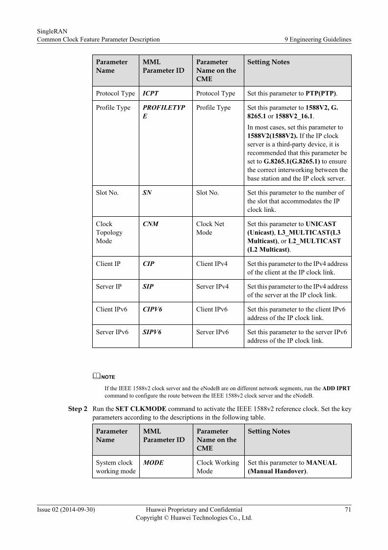
ParameterName
MMLParameter ID
ParameterName on theCME
Setting Notes
Protocol Type ICPT Protocol Type Set this parameter to PTP(PTP).
Profile Type PROFILETYPE
Profile Type Set this parameter to 1588V2, G.8265.1 or 1588V2_16.1.In most cases, set this parameter to1588V2(1588V2). If the IP clockserver is a third-party device, it isrecommended that this parameter beset to G.8265.1(G.8265.1) to ensurethe correct interworking between thebase station and the IP clock server.
Slot No. SN Slot No. Set this parameter to the number ofthe slot that accommodates the IPclock link.
ClockTopologyMode
CNM Clock NetMode
Set this parameter to UNICAST(Unicast), L3_MULTICAST(L3Multicast), or L2_MULTICAST(L2 Multicast).
Client IP CIP Client IPv4 Set this parameter to the IPv4 addressof the client at the IP clock link.
Server IP SIP Server IPv4 Set this parameter to the IPv4 addressof the server at the IP clock link.
Client IPv6 CIPV6 Client IPv6 Set this parameter to the client IPv6address of the IP clock link.
Server IPv6 SIPV6 Server IPv6 Set this parameter to the server IPv6address of the IP clock link.
NOTE
If the IEEE 1588v2 clock server and the eNodeB are on different network segments, run the ADD IPRTcommand to configure the route between the IEEE 1588v2 clock server and the eNodeB.
Step 2 Run the SET CLKMODE command to activate the IEEE 1588v2 reference clock. Set the keyparameters according to the descriptions in the following table.
ParameterName
MMLParameter ID
ParameterName on theCME
Setting Notes
System clockworking mode
MODE Clock WorkingMode
Set this parameter to MANUAL(Manual Handover).
SingleRANCommon Clock Feature Parameter Description 9 Engineering Guidelines
Issue 02 (2014-09-30) Huawei Proprietary and ConfidentialCopyright © Huawei Technologies Co., Ltd.
71

ParameterName
MMLParameter ID
ParameterName on theCME
Setting Notes
SelectedClock Source
CLKSRC Selected ClockSource
Set this parameter to IPCLK(IPClock).
IP Clock TimeSynchronization Mode
SYNMODE Synchronization Mode
Set this parameter to ABSOLUTE(ABSOLUTE), RELATIVE(RELATIVE), or OFF(OFF).
----End
Configuring a Common Synchronous Ethernet Reference Clock on the FDDeNodeB Side
Before configuring a common synchronous Ethernet reference clock, ensure that all transmissionequipment supports the synchronous Ethernet.
Step 1 Run the ADD SYNCETH command to add a synchronous Ethernet clock link. Set the keyparameters according to the descriptions in the following table.
ParameterName
MMLParameter ID
ParameterName on theCME
Setting Notes
Slot No. SN Slot No. Set this parameter to the number ofthe slot that accommodates thesynchronous Ethernet clock link.
Port No. PN Port No. Set this parameter to the number ofthe port that accommodates thesynchronous Ethernet clock link.
SSMSelection
SSM Synchronization StatusMessage
Set this parameter to DISABLE(DISABLE) or ENABLE(ENABLE).
Step 2 Run the SET CLKMODE command to activate the synchronous Ethernet reference clock. Setthe key parameters according to the descriptions in the following table.
Parameter Name MML ParameterID
Parameter Nameon the CME
Setting Notes
System clockworking mode
MODE Clock WorkingMode
Set this parameter toMANUAL(ManualHandover).
Selected ClockSource
CLKSRC Selected ClockSource
Set this parameter toSYNCETH(SyncEth Clock).
SingleRANCommon Clock Feature Parameter Description 9 Engineering Guidelines
Issue 02 (2014-09-30) Huawei Proprietary and ConfidentialCopyright © Huawei Technologies Co., Ltd.
72
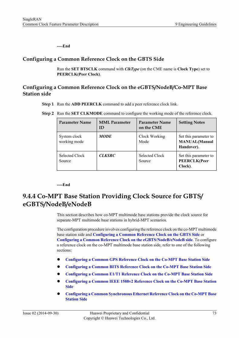
----End
Configuring a Common Reference Clock on the GBTS Side
Run the SET BTSCLK command with ClkType (on the CME name is Clock Type) set toPEERCLK(Peer Clock).
Configuring a Common Reference Clock on the eGBTS/NodeB/Co-MPT BaseStation side
Step 1 Run the ADD PEERCLK command to add a peer reference clock link.
Step 2 Run the SET CLKMODE command to configure the working mode of the reference clock.
Parameter Name MML ParameterID
Parameter Nameon the CME
Setting Notes
System clockworking mode
MODE Clock WorkingMode
Set this parameter toMANUAL(ManualHandover).
Selected ClockSource
CLKSRC Selected ClockSource
Set this parameter toPEERCLK(PeerClock).
----End
9.4.4 Co-MPT Base Station Providing Clock Source for GBTS/eGBTS/NodeB/eNodeB
This section describes how co-MPT multimode base stations provide the clock source forseparate-MPT multimode base stations in hybrid-MPT scenarios.
The configuration procedure involves configuring the reference clock on the co-MPT multimodebase station side and Configuring a Common Reference Clock on the GBTS Side orConfiguring a Common Reference Clock on the eGBTS/NodeB/eNodeB side. To configurea reference clock on the co-MPT multimode base station side, refer to one of the followingsections:
l Configuring a Common GPS Reference Clock on the Co-MPT Base Station Side
l Configuring a Common BITS Reference Clock on the Co-MPT Base Station Side
l Configuring a Common E1/T1 Reference Clock on the Co-MPT Base Station Side
l Configuring a Common IEEE 1588v2 Reference Clock on the Co-MPT Base StationSide
l Configuring a Common Synchronous Ethernet Reference Clock on the Co-MPT BaseStation Side
SingleRANCommon Clock Feature Parameter Description 9 Engineering Guidelines
Issue 02 (2014-09-30) Huawei Proprietary and ConfidentialCopyright © Huawei Technologies Co., Ltd.
73

Configuring a Common GPS Reference Clock on the Co-MPT Base Station SideBefore configuring a common GPS reference clock, ensure that the co-MPT multimode basestation has been configured with a USCU board.
Step 1 Run the ADD GPS command to add a GPS clock link.
Step 2 Run the SET CLKMODE command to activate the GPS reference clock. Set the key parametersaccording to the descriptions in the following table.
Parameter Name MML ParameterID
Parameter Nameon the CME
Setting Notes
System clockworking mode
MODE System ClockWorking Mode
Set this parameter toMANUAL(ManualHandover).
Selected ClockSource
CLKSRC Clock Source Type Set this parameter toGPS(GPS Clock).
----End
Configuring a Common BITS Reference Clock on the Co-MPT Base Station SideBefore configuring a common BITS reference clock, ensure that the co-MPT multimode basestation has been configured with a USCU board.
Step 1 Run the ADD BITS command to add a BITS clock link.
Step 2 Run the SET CLKMODE command to activate the BITS reference clock. Set the keyparameters according to the descriptions in the following table.
Parameter Name MML ParameterID
Parameter Nameon the CME
Setting Notes
System clockworking mode
MODE System ClockWorking Mode
Set this parameter toMANUAL(ManualHandover).
Selected ClockSource
CLKSRC Clock Source Type Set this parameter toBITS(BITS Clock).
----End
Configuring a Common E1/T1 Reference Clock on the Co-MPT Base Station SideBefore configuring a common E1/T1 reference clock, ensure that an E1/T1 clock link isavailable.
Step 1 Run the ADD LINECLK command to add an E1/T1 clock link. In this step, set Port Type(Port Type on the CME) to E1T1(E1T1).
Step 2 Run the SET CLKMODE command to activate the E1/T1 reference clock. Set the keyparameters according to the descriptions in the following table.
SingleRANCommon Clock Feature Parameter Description 9 Engineering Guidelines
Issue 02 (2014-09-30) Huawei Proprietary and ConfidentialCopyright © Huawei Technologies Co., Ltd.
74

Parameter Name MML ParameterID
Parameter Nameon the CME
Setting Notes
System clockworking mode
MODE System ClockWorking Mode
Set this parameter toMANUAL(ManualHandover).
Selected ClockSource
CLKSRC Clock Source Type Set this parameter toLINECLK(LineClock).
----End
Configuring a Common IEEE 1588v2 Reference Clock on the Co-MPT Base StationSide
Step 1 Run the ADD IPCLKLINK command to add an IEEE 1588v2 clock link. Set the key parametersaccording to the descriptions in the following table.
ParameterName
MMLParameterID
ParameterName on theCME
Setting Notes
ProtocolType
ICPT Protocol Type Set this parameter to PTP(PTP).
Profile Type PROFILETYPE
Profile Type Set this parameter to 1588V2, G.8265.1or 1588V2_16.1.In most cases, set this parameter to1588V2(1588V2). If the IP clock server isa third-party device, it is recommendedthat this parameter be set to G.8265.1(G.8265.1) to ensure the correct interworkingbetween the base station and the IP clockserver.
Slot No. SN Slot No. Set this parameter to the number of the slotthat accommodates the IP clock link.
ClockTopologyMode
CNM Clock NetMode
Set this parameter to UNICAST(Unicast), L3_MULTICAST(L3Multicast), or L2_MULTICAST(L2Multicast).
Client IP CIP Client IPv4 Set this parameter to the IPv4 address ofthe client at the IP clock link.
Server IP SIP Server IPv4 Set this parameter to the IPv4 address ofthe server at the IP clock link.
Client IPv6 CIPV6 Client IPv6 Set this parameter to the client IPv6address of the IP clock link.
SingleRANCommon Clock Feature Parameter Description 9 Engineering Guidelines
Issue 02 (2014-09-30) Huawei Proprietary and ConfidentialCopyright © Huawei Technologies Co., Ltd.
75

ParameterName
MMLParameterID
ParameterName on theCME
Setting Notes
Server IPv6 SIPV6 Server IPv6 Set this parameter to the server IPv6address of the IP clock link.
NOTE
If the IEEE 1588v2 clock server and the co-MPT multimode base station are on different network segments,run the ADD IPRT command to configure the route between the IEEE 1588v2 clock server and the co-MPT multimode base station.
Step 2 Run the SET CLKMODE command to activate the IEEE 1588v2 reference clock. Set the keyparameters according to the descriptions in the following table.
ParameterName
MMLParameter ID
Parameter Nameon the CME
Setting Notes
System clockworking mode
MODE Clock WorkingMode
Set this parameter to MANUAL(Manual Handover).
Selected ClockSource
CLKSRC Selected ClockSource
Set this parameter to IPCLK(IPClock).
IP Clock TimeSynchronization Mode
SYNMODE SynchronizationMode
Set this parameter toABSOLUTE(ABSOLUTE),RELATIVE(RELATIVE), orOFF(OFF).
----End
Configuring a Common Synchronous Ethernet Reference Clock on the Co-MPTBase Station Side
Before configuring a common synchronous Ethernet reference clock, ensure that all transmissionequipment supports the synchronous Ethernet.
Step 1 Run the ADD SYNCETH command to add a synchronous Ethernet clock link. Set the keyparameters according to the descriptions in the following table.
ParameterName
MMLParameter ID
Parameter Nameon the CME
Setting Notes
Slot No. SN Slot No. Set this parameter to the numberof the slot that accommodatesthe synchronous Ethernet clocklink.
SingleRANCommon Clock Feature Parameter Description 9 Engineering Guidelines
Issue 02 (2014-09-30) Huawei Proprietary and ConfidentialCopyright © Huawei Technologies Co., Ltd.
76

ParameterName
MMLParameter ID
Parameter Nameon the CME
Setting Notes
Port No. PN Port No. Set this parameter to the numberof the port that accommodatesthe synchronous Ethernet clocklink.
SSM Selection SSM SynchronizationStatus Message
Set this parameter to DISABLE(DISABLE) or ENABLE(ENABLE).
Step 2 Run the SET CLKMODE command to activate the synchronous Ethernet reference clock. Setthe key parameters according to the descriptions in the following table.
Parameter Name MML ParameterID
Parameter Nameon the CME
Setting Notes
System clockworking mode
MODE Clock WorkingMode
Set this parameter toMANUAL(ManualHandover).
Selected ClockSource
CLKSRC Selected ClockSource
Set this parameter toSYNCETH(SyncEth Clock).
----End
Configuring a Common Reference Clock on the GBTS SideRun the SET BTSCLK command with ClkType (the CME name is Clock Type) set toPEERCLK(Peer Clock).
Configuring a Common Reference Clock on the eGBTS/NodeB/eNodeB sideStep 1 Run the ADD PEERCLK command to add a peer reference clock link.
Step 2 Run the SET CLKMODE command to configure the working mode of the reference clock.
Parameter Name MML ParameterID
Parameter Nameon the CME
Setting Notes
System clockworking mode
MODE Clock WorkingMode
Set this parameter toMANUAL(ManualHandover).
Selected ClockSource
CLKSRC Selected ClockSource
Set this parameter toPEERCLK(PeerClock).
----End
SingleRANCommon Clock Feature Parameter Description 9 Engineering Guidelines
Issue 02 (2014-09-30) Huawei Proprietary and ConfidentialCopyright © Huawei Technologies Co., Ltd.
77

9.4.5 Co-MPT Base Station Supporting Common Reference Clockamong GSM, UMTS, and LTE
A co-MPT multimode base station supports the Common Clock feature. For details about howto configure a common GPS, BITS, E1/T1, IEEE1588V2, or synchronous Ethernet referenceclock, see section 9.4.4 Co-MPT Base Station Providing Clock Source for GBTS/eGBTS/NodeB/eNodeB.
Configuring a Common 1PPS+TOD Reference Clock
Step 1 Run the ADD TOD command to add a 1PPS+TOD clock link.
Step 2 Run the SET CLKMODE command to activate the GPS reference clock. Set the key parametersaccording to the descriptions in the following table.
Parameter Name MML ParameterID
Parameter Nameon the CME
Setting Notes
System clockworking mode
MODE System ClockWorking Mode
Set this parameter toMANUAL(ManualHandover).
Selected ClockSource
CLKSRC Clock Source Type Set this parameter toTOD(TOD Clock).
----End
Configuring a Common IEEE 1588v2+SyncE Reference Clock
Before configuring a common IEEE1588V2+SyncE reference clock, ensure that theIEEE1588V2 IP clock server and the synchronous Ethernet share a clock source.
Step 1 Run the ADD SYNCETH command to add a synchronous Ethernet clock link. Set the keyparameters according to the descriptions in the following table.
ParameterName
MMLParameter ID
ParameterName on theCME
Setting Notes
Slot No. SN Slot No. Set this parameter to the number of theslot that accommodates thesynchronous Ethernet clock link.
Port No. PN Port No. Set this parameter to the number of theport that accommodates thesynchronous Ethernet clock link.
SSMSelection
SSM Synchronization StatusMessage
Set this parameter to DISABLE(DISABLE) or ENABLE(ENABLE).
SingleRANCommon Clock Feature Parameter Description 9 Engineering Guidelines
Issue 02 (2014-09-30) Huawei Proprietary and ConfidentialCopyright © Huawei Technologies Co., Ltd.
78

ParameterName
MMLParameter ID
ParameterName on theCME
Setting Notes
SyncEthClock No.
LN SyncEth ClockNo.
Link No. 0 is synchronous-Ethernetinput and link No. 1 is synchronous-Ethernet output.
Step 2 Run the ADD IPCLKLINK command to add an IEEE 1588v2 clock link. Set the key parametersaccording to the descriptions in the following table.
ParameterName
MMLParameter ID
ParameterName on theCME
Setting Notes
ProtocolType
ICPT Protocol Type Set this parameter to PTP(PTP).
Profile Type PROFILETYPE
Profile Type Set this parameter to 1588V2, G.8265.1 or 1588V2_16.1.In most cases, set this parameter to1588V2(1588V2). If the IP clockserver is a third-party device, it isrecommended that this parameter beset to G.8265.1(G.8265.1) to ensurethe correct interworking between thebase station and the IP clock server.
Slot No. SN Slot No. Set this parameter to the number of theslot that accommodates the IP clocklink.
ClockTopologyMode
CNM Clock NetMode
Set this parameter to UNICAST(Unicast), L3_MULTICAST(L3Multicast), or L2_MULTICAST(L2Multicast).
Client IP CIP Client IPv4 Set this parameter to the IPv4 addressof the client at the IP clock link.
Server IP SIP Server IPv4 Set this parameter to the IPv4 addressof the server at the IP clock link.
Client IPv6 CIPV6 Client IPv6 Set this parameter to the client IPv6address of the IP clock link.
Server IPv6 SIPV6 Server IPv6 Set this parameter to the server IPv6address of the IP clock link.
SingleRANCommon Clock Feature Parameter Description 9 Engineering Guidelines
Issue 02 (2014-09-30) Huawei Proprietary and ConfidentialCopyright © Huawei Technologies Co., Ltd.
79

NOTE
If the IEEE 1588v2 clock server and the co-MPT multimode base station are on different network segments,run the ADD IPRT command to configure the route between the IEEE 1588v2 clock server and the co-MPT multimode base station.
Step 3 Run the SET CLKMODE command to activate the IEEE 1588v2+SyncE reference clock. Setthe key parameters according to the descriptions in the following table.
ParameterName
MMLParameter ID
Parameter Nameon the CME
Setting Notes
System clockworking mode
MODE Clock WorkingMode
Set this parameter toMANUAL(ManualHandover).
Selected ClockSource
CLKSRC Selected ClockSource
Set this parameter toSYNCETH+IPCLK(SyncEth Clock+IP Clock).
IP Clock TimeSynchronization Mode
SYNMODE SynchronizationMode
Set this parameter toABSOLUTE(ABSOLUTE), RELATIVE(RELATIVE), or OFF(OFF).
----End
9.5 Activation ObservationStep 1 Run the GSM MML command LST BTSCLK and the co-MPT multimode base station/NodeB/
eNodeB/eGBTS MML command DSP CLKSTAT to check whether the Common Clock featurehas been activated.
If... Then...
The reference clock type is the same as thepreset one
Configuring the reference clock succeeds andthe feature has been activated.
The reference clock type is different from thepreset one
Configuring the reference clock fails and thefeature is not activated.
Step 2 Check whether any related alarms are generated.
If... Then...
ALM-26276 Inter-System Site-LevelConfiguration Conflict is generated and thevalue of Configuration Item is ClockReference Type Configuration Conflict,indicating a clock reference typeconfiguration conflict
Configuring the reference clock fails and thefeature is not activated.
SingleRANCommon Clock Feature Parameter Description 9 Engineering Guidelines
Issue 02 (2014-09-30) Huawei Proprietary and ConfidentialCopyright © Huawei Technologies Co., Ltd.
80

----End
9.6 TroubleshootingIf ALM-26276 Inter-System Site-Level Configuration Conflict is generated, a clock referencetype configuration conflict occurs. That is, the base station of the current mode does not supportthis type of reference clock. If this occurs, you must check the configuration file and correct theclock reference type.
Alarm ID Alarm Name Configuration Item
26276 Inter-System Site-LevelConfiguration Conflict
Clock Reference TypeConfiguration Conflict
If the common reference clock is correctly configured but the base station cannot lock the clocksource within 30 minutes after it starts, you need to troubleshoot the common reference clockfault. For details, see section "Troubleshooting" in Synchronization Feature ParameterDescription for GSM, UMTS, or LTE.
SingleRANCommon Clock Feature Parameter Description 9 Engineering Guidelines
Issue 02 (2014-09-30) Huawei Proprietary and ConfidentialCopyright © Huawei Technologies Co., Ltd.
81

10 Parameters
Table 10-1 Parameter description
Parameter ID
NE MMLCommand
FeatureID
FeatureName
Description
MODE BTS3900,BTS3900WCDMA,BTS3900 LTE
SETCLKMODEDSPCLKSTATLSTCLKMODE
MRFD-210501
LBFD-003005
LBFD-00300501
LBFD-00300502
LBFD-00300503
LBFD-00300504
LBFD-00300505
LBFD-00300506
LOFD-003013
LOFD-00301301
LOFD-00301302
LOFD-00301303
LOFD-003023
BTSClock
SynchronizationClockSourceSwitchingManually orAutomaticallyFree-runningModeSynchronizationwithGPSSynchronizationwithBITSSynchronizationwith1PPS
Meaning: Indicates the working mode of the systemclock. Manual indicates that a clock source must bespecified by the user. Auto indicates that the systemautomatically selects a clock source based on thepriority and availability of the clock source. Freeindicates that the system clock works in free-runningmode, that is, the system clock does not trace anyreference clock source.GUI Value Range: AUTO(Auto), MANUAL(Manual),FREE(Free)Unit: NoneActual Value Range: AUTO, MANUAL, FREEDefault Value: FREE(Free)
SingleRANCommon Clock Feature Parameter Description 10 Parameters
Issue 02 (2014-09-30) Huawei Proprietary and ConfidentialCopyright © Huawei Technologies Co., Ltd.
82

Parameter ID
NE MMLCommand
FeatureID
FeatureName
Description
Synchronizationwith E1/T1EnhancedSynchronizationSynchronizationwithEthernet(ITU-TG.8261)IEEE1588 V2ClockSynchronizationClockover IP(Huaweiproprietary)IEEE1588v2overIPv6
SingleRANCommon Clock Feature Parameter Description 10 Parameters
Issue 02 (2014-09-30) Huawei Proprietary and ConfidentialCopyright © Huawei Technologies Co., Ltd.
83

Parameter ID
NE MMLCommand
FeatureID
FeatureName
Description
CLKSRC
BTS3900,BTS3900WCDMA,BTS3900 LTE
SETCLKMODELSTCLKMODE
MRFD-210501
LBFD-003005LBFD-00300501LBFD-00300503LBFD-00300504LBFD-00300505LBFD-00300506LOFD-003013LOFD-00301301LOFD-00301302LOFD-00301303LOFD-003023
BTSClock
Synchronization
ClockSourceSwitchingManually orAutomatically
SynchronizationwithGPS
SynchronizationwithBITS
Synchronizationwith1PPS
Synchronizationwith E1/T1
EnhancedSynchronization
SynchronizationwithEthernet(ITU-TG.8261)
IEEE1588 V2ClockSynchronization
Meaning: Indicates the type of the user-selected clocksource. The UMTS currently does not support "SyncEthClock+IP Clock" and "GPS Clock+SyncEth Clock"function.GUI Value Range: GPS(GPS Clock), BITS(BITSClock), IPCLK(IP Clock), SYNCETH(SyncEthClock), LINECLK(Line Clock), TOD(TOD Clock),PEERCLK(Peer Clock), SYNCETH+IPCLK(SyncEthClock+IP Clock), GPS+SYNCETH(GPS Clock+SyncEth Clock), INTERCLK(Inter Clock)Unit: NoneActual Value Range: GPS, BITS, IPCLK, SYNCETH,LINECLK, TOD, PEERCLK, SYNCETH+IPCLK,GPS+SYNCETH, INTERCLKDefault Value: GPS(GPS Clock)
SingleRANCommon Clock Feature Parameter Description 10 Parameters
Issue 02 (2014-09-30) Huawei Proprietary and ConfidentialCopyright © Huawei Technologies Co., Ltd.
84

Parameter ID
NE MMLCommand
FeatureID
FeatureName
Description
Clockover IP(Huaweiproprietary)IEEE1588v2overIPv6
ICPT BTS3900,BTS3900WCDMA,BTS3900 LTE
ADDIPCLKLINKLSTIPCLKLINK
WRFD-050501
GBFD-118606GBFD-118620
LOFD-00301301LOFD-00301302LOFD-00301303LOFD-003023
ClockSync onEthernetinNodeB
Clockover IPClockover IPsupport1588v2
SynchronizationwithEthernet(ITU-TG.8261)IEEE1588 V2ClockSynchronizationClockover IP(Huaweiproprietary)IEEE1588v2overIPv6
Meaning: Indicates the type of the IP clock protocol,which can be PTP or Huawei proprietary protocol. PTPincludes IEEE1588 V2, G.8265.1 and 1588V2_16.1.IEEE1588 V2, defined by the IEEE, supports both timesynchronization and frequency synchronization. G.8265.1 supports frequency synchronization only. 1588V2_16.1 supports both time synchronization andfrequency synchronization. Huawei proprietaryprotocol, which is the Huawei-defined IP clockprotocol, applies to the interconnection betweenHuawei equipment and supports frequencysynchronization only.GUI Value Range: HW_DEFINED(HuaWei DefinedProtocol), PTP(PTP Protocol)Unit: NoneActual Value Range: HW_DEFINED, PTPDefault Value: PTP(PTP Protocol)
SingleRANCommon Clock Feature Parameter Description 10 Parameters
Issue 02 (2014-09-30) Huawei Proprietary and ConfidentialCopyright © Huawei Technologies Co., Ltd.
85
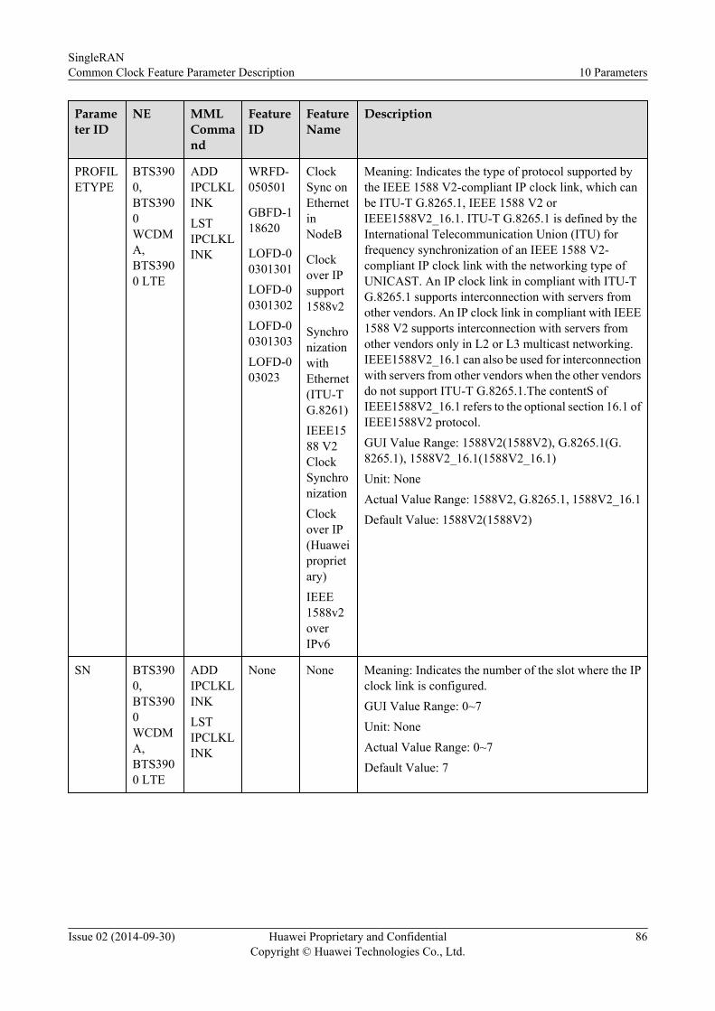
Parameter ID
NE MMLCommand
FeatureID
FeatureName
Description
PROFILETYPE
BTS3900,BTS3900WCDMA,BTS3900 LTE
ADDIPCLKLINKLSTIPCLKLINK
WRFD-050501
GBFD-118620
LOFD-00301301LOFD-00301302LOFD-00301303LOFD-003023
ClockSync onEthernetinNodeB
Clockover IPsupport1588v2
SynchronizationwithEthernet(ITU-TG.8261)IEEE1588 V2ClockSynchronizationClockover IP(Huaweiproprietary)IEEE1588v2overIPv6
Meaning: Indicates the type of protocol supported bythe IEEE 1588 V2-compliant IP clock link, which canbe ITU-T G.8265.1, IEEE 1588 V2 orIEEE1588V2_16.1. ITU-T G.8265.1 is defined by theInternational Telecommunication Union (ITU) forfrequency synchronization of an IEEE 1588 V2-compliant IP clock link with the networking type ofUNICAST. An IP clock link in compliant with ITU-TG.8265.1 supports interconnection with servers fromother vendors. An IP clock link in compliant with IEEE1588 V2 supports interconnection with servers fromother vendors only in L2 or L3 multicast networking.IEEE1588V2_16.1 can also be used for interconnectionwith servers from other vendors when the other vendorsdo not support ITU-T G.8265.1.The contentS ofIEEE1588V2_16.1 refers to the optional section 16.1 ofIEEE1588V2 protocol.GUI Value Range: 1588V2(1588V2), G.8265.1(G.8265.1), 1588V2_16.1(1588V2_16.1)Unit: NoneActual Value Range: 1588V2, G.8265.1, 1588V2_16.1Default Value: 1588V2(1588V2)
SN BTS3900,BTS3900WCDMA,BTS3900 LTE
ADDIPCLKLINKLSTIPCLKLINK
None None Meaning: Indicates the number of the slot where the IPclock link is configured.GUI Value Range: 0~7Unit: NoneActual Value Range: 0~7Default Value: 7
SingleRANCommon Clock Feature Parameter Description 10 Parameters
Issue 02 (2014-09-30) Huawei Proprietary and ConfidentialCopyright © Huawei Technologies Co., Ltd.
86

Parameter ID
NE MMLCommand
FeatureID
FeatureName
Description
CNM BTS3900,BTS3900WCDMA,BTS3900 LTE
ADDIPCLKLINKLSTIPCLKLINK
WRFD-050501
GBFD-118620
LOFD-00301301LOFD-00301302LOFD-00301303LOFD-003023
ClockSync onEthernetinNodeB
Clockover IPsupport1588v2
SynchronizationwithEthernet(ITU-TG.8261)IEEE1588 V2ClockSynchronizationClockover IP(Huaweiproprietary)IEEE1588v2overIPv6
Meaning: Indicates the networking type for the IP clock.The LTE currently does not support L3 Multicastfunction.GUI Value Range: UNICAST(Unicast),L3_MULTICAST(L3 Multicast), L2_MULTICAST(L2 Multicast)Unit: NoneActual Value Range: UNICAST, L3_MULTICAST,L2_MULTICASTDefault Value: UNICAST(Unicast)
SingleRANCommon Clock Feature Parameter Description 10 Parameters
Issue 02 (2014-09-30) Huawei Proprietary and ConfidentialCopyright © Huawei Technologies Co., Ltd.
87

Parameter ID
NE MMLCommand
FeatureID
FeatureName
Description
CIP BTS3900,BTS3900WCDMA,BTS3900 LTE
ADDIPCLKLINKDSPIPCLKLINKLSTIPCLKLINK
WRFD-050501
GBFD-118606GBFD-118620
LOFD-00301301LOFD-00301302LOFD-00301303LOFD-003023
ClockSync onEthernetinNodeB
Clockover IPClockover IPsupport1588v2
SynchronizationwithEthernet(ITU-TG.8261)IEEE1588 V2ClockSynchronizationClockover IP(Huaweiproprietary)IEEE1588v2overIPv6
Meaning: Indicates the client IPv4 address of the IPclock link.GUI Value Range: Valid IP addressUnit: NoneActual Value Range: Valid IP addressDefault Value: 0.0.0.0
SingleRANCommon Clock Feature Parameter Description 10 Parameters
Issue 02 (2014-09-30) Huawei Proprietary and ConfidentialCopyright © Huawei Technologies Co., Ltd.
88

Parameter ID
NE MMLCommand
FeatureID
FeatureName
Description
SIP BTS3900,BTS3900WCDMA,BTS3900 LTE
ADDIPCLKLINKLSTIPCLKLINK
WRFD-050501
GBFD-118606GBFD-118620
LOFD-00301301LOFD-00301302LOFD-00301303LOFD-003023
ClockSync onEthernetinNodeB
Clockover IPClockover IPsupport1588v2
SynchronizationwithEthernet(ITU-TG.8261)IEEE1588 V2ClockSynchronizationClockover IP(Huaweiproprietary)IEEE1588v2overIPv6
Meaning: Indicates the server IPv4 address of the IPclock link.GUI Value Range: Valid IP addressUnit: NoneActual Value Range: Valid IP addressDefault Value: 0.0.0.0
SingleRANCommon Clock Feature Parameter Description 10 Parameters
Issue 02 (2014-09-30) Huawei Proprietary and ConfidentialCopyright © Huawei Technologies Co., Ltd.
89

Parameter ID
NE MMLCommand
FeatureID
FeatureName
Description
SYNMODE
BTS3900,BTS3900WCDMA,BTS3900 LTE
SETCLKMODELSTCLKMODE
WRFD-050501
GBFD-118620
LOFD-003013LOFD-00301301LOFD-00301302LOFD-00301303LOFD-003023
ClockSync onEthernetinNodeB
Clockover IPsupport1588v2
EnhancedSynchronizationSynchronizationwithEthernet(ITU-TG.8261)IEEE1588 V2ClockSynchronizationClockover IP(Huaweiproprietary)IEEE1588v2overIPv6
Meaning: Indicates the mode of scheduledsynchronization for the IP clock link. In ABSOLUTEmode, the system clock obtains synchronization signalsfrom the clock server at a fixed time every few days untilthe system clock is stable. In RELATIVE mode, thesystem clock obtains synchronization signals from theclock server at regular intervals until the system clockis stable. In OFF mode, the system clock obtains onlymessages from the clock server in real time. The LTEcurrently does not support this function.GUI Value Range: ABSOLUTE(ABSOLUTE),RELATIVE(RELATIVE), OFF(OFF)Unit: NoneActual Value Range: ABSOLUTE, RELATIVE, OFFDefault Value: OFF(OFF)
SN BTS3900,BTS3900WCDMA,BTS3900 LTE
ADDSYNCETHLSTSYNCETH
None None Meaning: Indicates the number of the slot where thesynchronous-Ethernet clock link is configured.GUI Value Range: 0~7Unit: NoneActual Value Range: 0~7Default Value: 7
SingleRANCommon Clock Feature Parameter Description 10 Parameters
Issue 02 (2014-09-30) Huawei Proprietary and ConfidentialCopyright © Huawei Technologies Co., Ltd.
90

Parameter ID
NE MMLCommand
FeatureID
FeatureName
Description
PN BTS3900,BTS3900WCDMA,BTS3900 LTE
ADDSYNCETHLSTSYNCETH
WRFD-050502
GBFD-118202
LOFD-003013LOFD-00301301
ClockSync onEthernet
SynchronousEthernet
EnhancedSynchronizationSynchronizationwithEthernet(ITU-TG.8261)
Meaning: Indicates the number of the port where thesynchronous-Ethernet clock link is configured.GUI Value Range: 0~5Unit: NoneActual Value Range: 0~5Default Value: 0
SSM BTS3900,BTS3900WCDMA,BTS3900 LTE
ADDSYNCETHMODSYNCETHDSPSYNCETHLSTSYNCETH
WRFD-050502
GBFD-118202
LOFD-003013LOFD-00301301
ClockSync onEthernet
SynchronousEthernet
EnhancedSynchronizationSynchronizationwithEthernet(ITU-TG.8261)
Meaning: Indicates whether handling of SSM frames issupported.The setting of this parameter is consistentwith the setting on the Ethernet clock server. Thesynchronization status message (SSM) carries clockquality information, which is specified in ITU-T. Thisparameter is valid only when the synchronous-Ethernetclock link is of the input type.GUI Value Range: DISABLE(DISABLE), ENABLE(ENABLE)Unit: NoneActual Value Range: DISABLE, ENABLEDefault Value: DISABLE(DISABLE)
SingleRANCommon Clock Feature Parameter Description 10 Parameters
Issue 02 (2014-09-30) Huawei Proprietary and ConfidentialCopyright © Huawei Technologies Co., Ltd.
91

Parameter ID
NE MMLCommand
FeatureID
FeatureName
Description
CIPV6 BTS3900,BTS3900WCDMA,BTS3900 LTE
ADDIPCLKLINKDSPIPCLKLINKLSTIPCLKLINK
WRFD-050501
GBFD-118620
LOFD-00301301LOFD-00301302LOFD-00301303LOFD-003023
ClockSync onEthernetinNodeB
Clockover IPsupport1588v2
SynchronizationwithEthernet(ITU-TG.8261)IEEE1588 V2ClockSynchronizationClockover IP(Huaweiproprietary)IEEE1588v2overIPv6
Meaning: Indicates the client IPv6 address of the IPclock link. The UMTS currently does not support thisfunction.GUI Value Range: Valid IP addressUnit: NoneActual Value Range: Valid IP addressDefault Value: 0:0:0:0:0:0:0:0
SingleRANCommon Clock Feature Parameter Description 10 Parameters
Issue 02 (2014-09-30) Huawei Proprietary and ConfidentialCopyright © Huawei Technologies Co., Ltd.
92
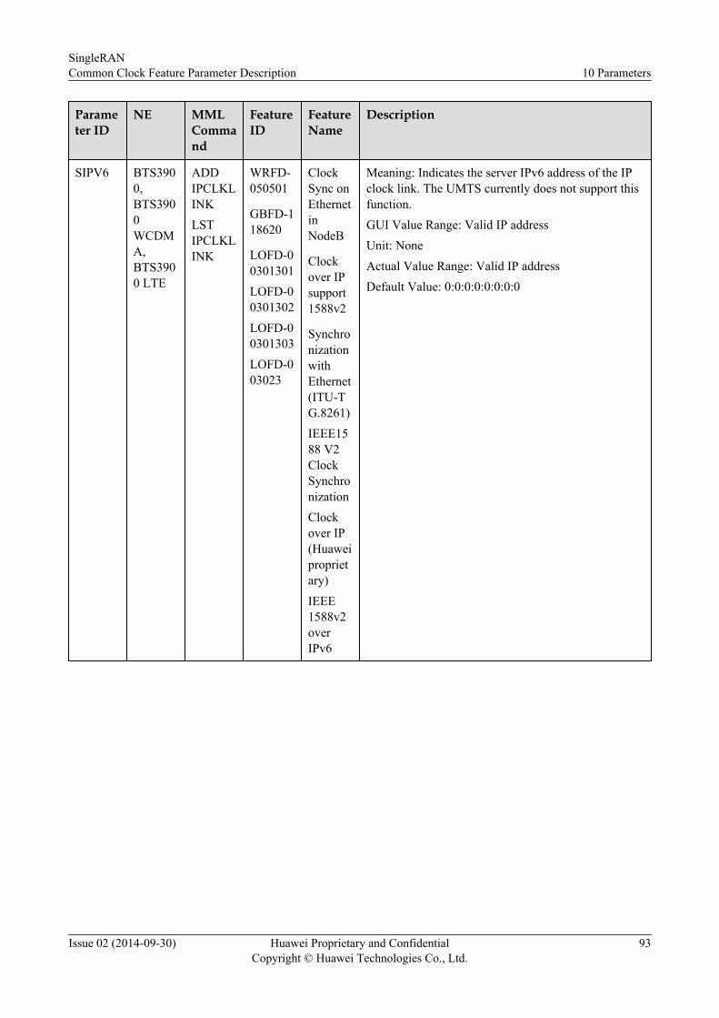
Parameter ID
NE MMLCommand
FeatureID
FeatureName
Description
SIPV6 BTS3900,BTS3900WCDMA,BTS3900 LTE
ADDIPCLKLINKLSTIPCLKLINK
WRFD-050501
GBFD-118620
LOFD-00301301LOFD-00301302LOFD-00301303LOFD-003023
ClockSync onEthernetinNodeB
Clockover IPsupport1588v2
SynchronizationwithEthernet(ITU-TG.8261)IEEE1588 V2ClockSynchronizationClockover IP(Huaweiproprietary)IEEE1588v2overIPv6
Meaning: Indicates the server IPv6 address of the IPclock link. The UMTS currently does not support thisfunction.GUI Value Range: Valid IP addressUnit: NoneActual Value Range: Valid IP addressDefault Value: 0:0:0:0:0:0:0:0
SingleRANCommon Clock Feature Parameter Description 10 Parameters
Issue 02 (2014-09-30) Huawei Proprietary and ConfidentialCopyright © Huawei Technologies Co., Ltd.
93

Parameter ID
NE MMLCommand
FeatureID
FeatureName
Description
LN BTS3900,BTS3900WCDMA,BTS3900 LTE
ADDSYNCETHDSPSYNCETHMODSYNCETHRMVSYNCETHLSTSYNCETH
WRFD-050502
GBFD-118202
LOFD-003013LOFD-00301301
ClockSync onEthernet
SynchronousEthernet
EnhancedSynchronizationSynchronizationwithEthernet(ITU-TG.8261)
Meaning: Indicates the number of the synchronous-Ethernet clock link. A maximum of two links can beconfigured currently.GUI Value Range: 0~1Unit: NoneActual Value Range: 0~1Default Value: 0
SingleRANCommon Clock Feature Parameter Description 10 Parameters
Issue 02 (2014-09-30) Huawei Proprietary and ConfidentialCopyright © Huawei Technologies Co., Ltd.
94

11 Counters
There are no specific counters associated with this feature.
SingleRANCommon Clock Feature Parameter Description 11 Counters
Issue 02 (2014-09-30) Huawei Proprietary and ConfidentialCopyright © Huawei Technologies Co., Ltd.
95

12 Glossary
For the acronyms, abbreviations, terms, and definitions, see the Glossary.
SingleRANCommon Clock Feature Parameter Description 12 Glossary
Issue 02 (2014-09-30) Huawei Proprietary and ConfidentialCopyright © Huawei Technologies Co., Ltd.
96

13 Reference Documents
1. Common Transmission Feature Parameter Description for SingleRAN2. Synchronization Feature Parameter Description for GSM BSS, WCDMA RAN, and
eRAN
SingleRANCommon Clock Feature Parameter Description 13 Reference Documents
Issue 02 (2014-09-30) Huawei Proprietary and ConfidentialCopyright © Huawei Technologies Co., Ltd.
97