Commissioning Ultrasite EDGE BTS
290
Commissioning UltraSite EDGE BTS dn03398316 Issue 1 en # Nokia Corporation Nokia Proprietary and Confidential 1 (290) 469851A.606 Nokia UltraSite EDGE BTS, Release 6, Product Documentation
-
Upload
dancmscribd -
Category
Documents
-
view
1.656 -
download
39
Transcript of Commissioning Ultrasite EDGE BTS

5/14/2018 Commissioning Ultrasite EDGE BTS - slidepdf.com
http://slidepdf.com/reader/full/commissioning-ultrasite-edge-bts 1/290
Commissioning UltraSite EDGE
BTS
dn03398316Issue 1 en
# Nokia CorporationNokia Proprietary and Confidential
1 (290)
469851A.606
Nokia UltraSite EDGE BTS, Release 6, ProductDocumentation

5/14/2018 Commissioning Ultrasite EDGE BTS - slidepdf.com
http://slidepdf.com/reader/full/commissioning-ultrasite-edge-bts 2/290
The information in this document is subject to change without notice and describes only theproduct defined in the introduction of this documentation. This document is intended for the useof Nokia's customers only for the purposes of the agreement under which the document issubmitted, and no part of it may be reproduced or transmitted in any form or means without the
prior written permission of Nokia. The document has been prepared to be used by professionaland properly trained personnel, and the customer assumes full responsibility when using it.Nokia welcomes customer comments as part of the process of continuous development andimprovement of the documentation.
The information or statements given in this document concerning the suitability, capacity, or performance of the mentioned hardware or software products cannot be considered binding butshall be defined in the agreement made between Nokia and the customer. However, Nokia hasmade all reasonable efforts to ensure that the instructions contained in the document areadequate and free of material errors and omissions. Nokia will, if necessary, explain issueswhich may not be covered by the document.
Nokia's liability for any errors in the document is limited to the documentary correction of errors.NOKIA WILL NOT BE RESPONSIBLE IN ANY EVENT FOR ERRORS IN THIS DOCUMENTOR FOR ANY DAMAGES, INCIDENTAL OR CONSEQUENTIAL (INCLUDING MONETARYLOSSES), that might arise from the use of this document or the information in it.
This document and the product it describes are considered protected by copyright according tothe applicable laws.
NOKIA logo is a registered trademark of Nokia Corporation.
Other product names mentioned in this document may be trademarks of their respectivecompanies, and they are mentioned for identification purposes only.
Copyright © Nokia Corporation 2004. All rights reserved.
2 (290) # Nokia CorporationNokia Proprietary and Confidential
dn03398316Issue 1 en
Commissioning UltraSite EDGE BTS
5/14/2018 Commissioning Ultrasite EDGE BTS - slidepdf.com
http://slidepdf.com/reader/full/commissioning-ultrasite-edge-bts 3/290
Contents
Contents 3
1 Statutory information 91.1 CE Marking 91.2 FCC Statement 10
2 Overview of commissioning UltraSite EDGE BTS 112.1 Overview of commissioning UltraSite EDGE BTS 11
3 Software descriptions for UltraSite EDGE BTS 133.1 Network Management System (NMS)/NetAct and BSC software 133.2 Nokia SiteWizard software 133.2.1 Contents 13
3.2.2 Installation 143.2.3 BTS Manager 153.3 BTS software 16
4 Preparing to commission UltraSite EDGE BTS 174.1 Connecting LMP cable for commissioning UltraSite EDGE BTS 174.2 Powering ON UltraSite EDGE BTS 194.3 Setting the Base Operation and Interfaces (BOIx) unit 13MHz clock before
commissioning the UltraSite EDGE BTS 20
5 Remote BTS Manager Setup 235.1 Remote BTS Manager Setup 23
5.2 Rules for EDAP transmission connections 305.3 Installing BTS Manager 325.4 Installing BTS Hub Manager 33
6 Using Site Wizard commissioning software 376.1 Overview of using Hub Manager of Site Wizard to commission and
manage UltraSite EDGE BTS 376.2 Overview of using BTS Manager of Site Wizard to commission and
manage UltraSite EDGE BTS 386.3 Software compatibility of UltraSite EDGE BTS 396.3.1 Compatibility between BTS hardware and BTS software 396.3.2 Compatibility between BTS, SiteWizard, BSC, NMS/2000/NetAct and LMU
software 48
6.3.3 Compatibility between new features of UltraSite EDGE BTS softwarerelease CX3.3 and other network elements 50
6.4 ITN hardware and software compatibility 516.4.1 ITN versions 516.4.2 ITN HW compatibility 536.4.3 ITN HW/SW compatibility 536.5 ITN compatibility in BSS transmission networks 54
7 Commissioning GSM/EDGE UltraSite EDGE BTS 577.1 Overview of commissioning GSM/EDGE UltraSite EDGE BTS 57
dn03398316Issue 1 en
# Nokia CorporationNokia Proprietary and Confidential
3 (290)
Contents

5/14/2018 Commissioning Ultrasite EDGE BTS - slidepdf.com
http://slidepdf.com/reader/full/commissioning-ultrasite-edge-bts 4/290
7.2 Hub configuration of GSM/EDGE UltraSite EDGE BTS 607.2.1 Manual Hub configuration of UltraSite EDGE BTS 607.2.2 Defining Line Interface (LIF) settings of UltraSite EDGE BTS FXC E1/T1
units 61
7.2.3 Defining Line Interface (LIF) settings of UltraSite EDGE BTS FXC RRIunits 63
7.2.4 Adjusting identification settings 657.2.5 Adjusting service interface settings 667.2.6 Configuring radio units for FXC RRI units of UltraSite EDGE BTS 687.2.7 Adjusting synchronisation settings of a managed node for UltraSite EDGE
BTS 787.2.8 Adjusting synchronisation loop bit settings of UltraSite EDGE BTS 797.2.9 Adjusting Q1 management settings for UltraSite EDGE BTS 807.2.10 Adjusting alarm property settings 827.2.11 Allocating F(X)C transmission capacity of UltraSite EDGE BTS 847.2.12 Creating bi-directional cross-connections for UltraSite EDGE BTS 87
7.2.13 Overview of upgrading the node manager and node software 907.2.14 Installing software from Nokia SiteWizard 917.2.15 Checking the transmission unit product codes and versions 927.2.16 Downloading FXC unit software 957.2.17 Copying software between transmission units 1017.2.18 Downloading software to radio outdoor units 1047.2.19 Installing transmission units logically with the manager 1077.2.20 Uninstalling transmission units logically with the manager 1087.2.21 Overview of managing cross-connections 1097.2.22 Adding cross-connections 1157.2.23 Adding cross-connections in the graphic view 1207.2.24 Modifying cross-connections 1227.2.25 Creating and exporting a cross-connection file 122
7.2.26 Importing a cross-connection file 1237.2.27 Managing cross-connection banks 1247.2.28 Removing cross-connections 1257.3 Administering UltraSite BTS Hub 1257.3.1 Starting the node manager 1257.3.2 Using UltraSite BTS Hub or MetroHub Manager online help 1267.3.3 Overview of connecting to the node online 1277.3.4 Connecting locally via LMP 1287.3.5 Connecting via Q1 address 1307.3.6 Connecting to the node offline 1327.3.7 Resetting transmission units 1337.3.8 Saving node information in a file 135
7.3.9 Restoring backup settings from a file 1387.3.10 Creating a configuration report 1417.3.11 Printing information 1437.4 C o nf ig ur i ng GS M/ ED G E Ul tr a S it e E DG E BT S fo r ma n u al
commissioning 1447.4.1 Creating a new HW configuration to commission GSM/EDGE UltraSite
EDGE BTS 1447.4.2 Using an existing HW configuration to commission GSM/EDGE UltraSite
EDGE BTS 1477.5 Commissioning GSM/EDGE UltraSite EDGE BTS with XML Configuration
4 (290) # Nokia CorporationNokia Proprietary and Confidential
dn03398316Issue 1 en
Commissioning UltraSite EDGE BTS

5/14/2018 Commissioning Ultrasite EDGE BTS - slidepdf.com
http://slidepdf.com/reader/full/commissioning-ultrasite-edge-bts 5/290
File 1517.5.1 Commissioning UltraSite EDGE BTS based on an off-line node file 1517.5.2 Editing an XML file for UltraSite EDGE BTS 1537.5.3 Creating a node off-line file for UltraSite EDGE BTS 154
7.5.4 Setting obligatory settings for FlexiHopper 1557.5.5 Setting obligatory settings for MetroHopper 1647.5.6 Using off-line node file for commissioning of UltraSite EDGE BTS 1667.6 Manual commissioning of GSM/EDGE UltraSite EDGE BTS 1687.6.1 Manual commissioning of UltraSite EDGE BTS 1687.6.2 Entering initial settings for manual commissioning of UltraSite EDGE
BTS 1697.6.3 Defining Line Interface (LIF) settings of transmission (FC E1/T1) units of
UltraSite EDGE BTS 1747.6.4 Defining synchronisation settings of transmission (FC E1/T1) units of
UltraSite EDGE BTS 1757.7 Using the Macro Recorder 175
7.7.1 Recording a macro 1757.7.2 Running a macro 178
8 Integration of UltraSite EDGE BTS co-site to Talk-family BTS 1818.1 Integrating UltraSite EDGE BTS co-site to Talk-family BTS 1818.2 Verifying co-site functionality 1828.2.1 Verifying functionality of UltraSite EDGE BTS co-site with Talk-family BTS
with down-time consideration 1828.2.2 Verifying functionality of UltraSite EDGE BTS co-site with Talk-family BTS
without down-time consideration 183
9 Completing commissioning 1859.1 Verifying commissioning 1859.2 Closing connection to AXC 1879.3 Powering down UltraSite EDGE BTS 188
10 Test and activate 18910.1 Overview of testing UltraSite EDGE BTS 18910.2 Powering on UltraSite EDGE BTS at a new site 19010.3 Testing UltraSite EDGE BTS with the commissioning wizard 19110.4 Running a TRX test for UltraSite EDGE BTS 19410.5 Running an Abis loop test for UltraSite EDGE BTS 19610.6 Commissioning reports for UltraSite EDGE BTS 19810.6.1 HW configuration report 19810.6.2 Transmission Configuration Report 199
10.6.3 BTS commissioning report 201
11 Commissioning windows of UltraSite EDGE BTS 20311.1 BTS HW Configurator/Create New Configuration windows 20411.1.1 Configuration Wizard window of BTS HW Configurator 20411.1.2 Select Sector Configuration window of BTS HW Configurator 20511.1.3 Modify Sector and Network window of BTS HW Configurator 20611.1.4 Define TSx Configuration window of BTS HW Configurator 20711.1.5 Define RX Diversity Cabling window of BTS HW Configurator 20811.1.6 Define Antenna Settings window of BTS HW Configurator 209
dn03398316Issue 1 en
# Nokia CorporationNokia Proprietary and Confidential
5 (290)
Contents

5/14/2018 Commissioning Ultrasite EDGE BTS - slidepdf.com
http://slidepdf.com/reader/full/commissioning-ultrasite-edge-bts 6/290
11.1.7 Report of New Configuration window of BTS HW Configurator 21011.2 BTS HW Configurator/Check BTS Configuration and Update BTS
windows 21111.2.1 Configuration Wizard window of BTS HW Configurator 211
11.2.2 Select Configuration window of BTS HW Configurator 21211.2.3 BTS Connection window of BTS HW Configurator 21311.2.4 Cabinet Information window of BTS HW Configurator 21411.2.5 BB2-TSx Cross-connections window of BTS HW Configurator 21511.2.6 Current Cabling window of BTS HW Configurator 21611.2.7 Antenna Settings window of BTS HW Configurator 21711.2.8 Passive Units window of BTS HW Configurator 21811.2.9 BTS Configuration Report window of BTS HW Configurator 21911.3 UltraSite BTS Hub Manager windows 22011.3.1 Equipment - Address: window of UltraSite BTS Hub Manager 22011.3.2 LIF Settings window of UltraSite BTS Hub Manager 22111.3.3 LIF Settings window for T1 100 ohm mode of UltraSite BTS Hub
Manager 22211.3.4 Unit settings with FXC RRI unit setting window of UltraSite BTS HubManager 224
11.3.5 Platform interface tab of settings window of UltraSite BTS Hub Manager 225
11.3.6 Flexbus Settings window of RRI Manager 22611.3.7 Flexbus 1 - FlexiHopper Settings window of RRI Manager 22711.3.8 Flexbus 2 - MetroHopper General Settings window of RRI Manager 22811.3.9 Flexbus 2 - MetroHopper Manual Channel Selection window of RRI
Manager 22911.3.10 Summary of Commissioning Settings window of RRI Manager 23011.3.11 Monitoring Hop window of UltraSite BTS Hub Manager 23111.3.12 Synchronisation window 232
11.3.13 Add EOC window of UltraSite BTS Hub Manager 23211.3.14 Traffic Manager window of UltraSite BTS Hub Manager 23311.3.15 Add Cross-connection Wizard - TX1/RX1 window of UltraSite BTS Hub
Manager 23411.3.16 Overview window of UltraSite BTS Hub Manager 23511.3.17 OutdoorUnit1 - FlexiHopper window of UltraSite BTS Hub Manager 23611.3.18 RF tab of OutdoorUnit1 - MetroHopper window of UltraSite BTS Hub
Manager 23711.3.19 Commissioning settings tab of OutdoorUnit1 - MetroHopper window of
UltraSite BTS Hub Manager 23811.3.20 Welcome window of UltraSite BTS Hub Commissioning Wizard 23911.3.21 Testing window of UltraSite BTS Hub Commissioning Wizard 240
11.3.22 Accept Site Selection (File/Site ID/Site) window of UltraSite BTS HubCommissioning Wizard 241
11.3.23 Accept Site Selection (Expected Equipment) window of UltraSite BTS HubCommissioning Wizard 242
11.3.24 Check Hops window of UltraSite BTS Hub Commissioning Wizard 24311.3.25 End window of UltraSite BTS Hub Commissioning Wizard 24411.3.26 BTS Commissioning Wizard window of Nokia BTS Manager 24511.3.27 Set Transmission Parameters window of BTS Commissioning Wizard 24611.3.28 Transmission configuration window of BTS Commissioning Wizard 24711.3.29 BTS Test Reporting window of BTS Commissioning Wizard 248
6 (290) # Nokia CorporationNokia Proprietary and Confidential
dn03398316Issue 1 en
Commissioning UltraSite EDGE BTS

5/14/2018 Commissioning Ultrasite EDGE BTS - slidepdf.com
http://slidepdf.com/reader/full/commissioning-ultrasite-edge-bts 7/290
11.3.30 EAC Input Settings window of BTS Commissioning Wizard 24911.3.31 EAC Output Settings window of BTS Commissioning Wizard 25011.3.32 BTS Commissioning Report window of BTS Commissioning Wizard 25111.3.33 Sychronization window of UltraSite BTS Hub manager 252
12 Glossary 25312.1 Glossary for UltraSite EDGE BTS 25312.1.1 Abbreviations and acronyms 25312.1.2 Terms 269
Related Topics 279
dn03398316Issue 1 en
# Nokia CorporationNokia Proprietary and Confidential
7 (290)
Contents

5/14/2018 Commissioning Ultrasite EDGE BTS - slidepdf.com
http://slidepdf.com/reader/full/commissioning-ultrasite-edge-bts 8/290
8 (290) # Nokia CorporationNokia Proprietary and Confidential
dn03398316Issue 1 en
Commissioning UltraSite EDGE BTS

5/14/2018 Commissioning Ultrasite EDGE BTS - slidepdf.com
http://slidepdf.com/reader/full/commissioning-ultrasite-edge-bts 9/290
1 Statutory information
1.1 CE Marking
Standard Description
. Hereby, Nokia Corporation, declares
that this Nokia UltraSite EDGE Base
Station is in compliance with the
essential requirements and other
relevant provisions of Directive: 1999/5/
EC.
0168
dn03398316Issue 1 en
# Nokia CorporationNokia Proprietary and Confidential
9 (290)
Statutory information

5/14/2018 Commissioning Ultrasite EDGE BTS - slidepdf.com
http://slidepdf.com/reader/full/commissioning-ultrasite-edge-bts 10/290
1.2 FCC Statement
Standard Description
FCC Statement Hereby, Nokia Corporation declares that
this Nokia UltraSite EDGE Base Station
is in compliance with the essential
requirements and other relevant
provisions of Directive: 1999/5/EC.
The product is marked with the CE
marking and Notified Body number
according to the Directive 1999/5/EC.
This equipment has been tested and
found to comply with the limits for a
Class B digital device, pursuant to part15 of the FCC Rules. These limits are
designed to provide reasonable
protection against harmful interference
in a residential installation. This
equipment generates, uses and can
radiate radio frequency energy and, if
not installed and used in accordance
with the instructions, may cause harmful
interference to radio communications.
However, there is no guarantee that
interference will not occur in a particular
installation. Changes or modifications
not expressly approved by the party
responsible for compliance could voidthe user s authority to operate the
equipment. The term IC: before the
radio certification number only signifies
that Industry Canada technical
specifications were met.
10 (290) # Nokia CorporationNokia Proprietary and Confidential
dn03398316Issue 1 en
Commissioning UltraSite EDGE BTS

5/14/2018 Commissioning Ultrasite EDGE BTS - slidepdf.com
http://slidepdf.com/reader/full/commissioning-ultrasite-edge-bts 11/290
2 Overview of commissioning UltraSite
EDGE BTS
2.1 Overview of commissioning UltraSite EDGE BTS
Before you start
Before commissioning, the physical installation of the BTS (units, cabling,
antennas and radios) must be complete.
Summary
Caution
Nokia recommends that only properly trained and authorised personnel perform
commissioning operations on any Nokia BTS.
Steps
1. Connect the LMP cable.
2. Power on the UltraSite EDGE BTS.
3. Set the BOIx unit 13 MHz clock.
4. Install BTS Manager.
5. Install BTS Hub Manager.
6. Install PSM Manager.
7. Commission the BTS.
dn03398316Issue 1 en
# Nokia CorporationNokia Proprietary and Confidential
11 (290)
Overview of commissioning UltraSite EDGE BTS

5/14/2018 Commissioning Ultrasite EDGE BTS - slidepdf.com
http://slidepdf.com/reader/full/commissioning-ultrasite-edge-bts 12/290
a. Commission the UltraSite EDGE BTS.
b. Commission the UltraSite EDGE BTS with IBBU.
c. Commission the UltraSite EDGE BTS with WCDMA upgrade.
12 (290) # Nokia CorporationNokia Proprietary and Confidential
dn03398316Issue 1 en
Commissioning UltraSite EDGE BTS

5/14/2018 Commissioning Ultrasite EDGE BTS - slidepdf.com
http://slidepdf.com/reader/full/commissioning-ultrasite-edge-bts 13/290
3 Software descriptions for UltraSite EDGE
BTS
3.1 Network Management System (NMS)/NetAct and
BSC software
NMS 2000/NetAct software manages the entire GSM/EDGE network, including
UltraSite EDGE BTS, using the BSC. This remote software minimises the need
for on-site BTS management. NMS 2000/NetAct software incorporates a full
range of functions from fault, performance and configuration management to
transmission, trouble and security management.
For more information, see Nokia NMS/NetAct documentation.
3.2 Nokia SiteWizard software
3.2.1 Contents
Nokia SiteWizard is a collection of software used to manage UltraSite EDGE
BTS on-site. The applications run under Windows NT 4.0, Windows 95,
Windows 98 or Windows 2000. For detailed system requirements, see Release
Notes document.
Nokia SiteWizard is an application package for the commissioning and
maintenance of Nokia UltraSite and MetroSite GSM base stations. The CD-ROM
contains manager applications for the BTS and related transmission equipment on
a BTS site.
Nokia SiteWizard includes the following applications related to UltraSite EDGE
BTS:
dn03398316Issue 1 en
# Nokia CorporationNokia Proprietary and Confidential
13 (290)
Software descriptions for UltraSite EDGE BTS
5/14/2018 Commissioning Ultrasite EDGE BTS - slidepdf.com
http://slidepdf.com/reader/full/commissioning-ultrasite-edge-bts 14/290
. Nokia BTS Manager for managing UltraSite EDGE BTS
. Nokia BTS Hardware Configurator for configuring the UltraSite EDGE
BTS cabinet
. Nokia RRI Manager for FXC RRI transmission unit
. Nokia E1/T1 Manager for FC E1/T1, FXC E1, and FXC E1/T1
transmission units
. Nokia Hopper Manager for Nokia MetroHopper and FlexiHopper Radio
. Nokia UltraSite BTS Hub Manager for commissioning the FXC
transmission unit in the BTS hub
. Nokia SCF Editor
Note
The Nokia SiteWizard software package also contains manager applications for
other Nokia BTS products. These applications are not included in the previous
list.
Only BTS HWConfigurator, UltraSite BTS Hub Manager and BTS Manager are
directly used in the commissioning.
Note
Only one application can be communicating with the BTS at a time. Close BTS
HW Configurator before starting UltraSite BTS Hub Manager, and close Hub
Manager before starting BTS Manager.
3.2.2 Installation
The installation program of Nokia SiteWizard installs the applications on the PC
hard disk and creates the Nokia Applications submenu in the Start | Programs
menu in Windows. You can launch the applications from this menu. For more
information on the installation, see instructions on the Nokia SiteWizard CD-
ROM case.
14 (290) # Nokia CorporationNokia Proprietary and Confidential
dn03398316Issue 1 en
Commissioning UltraSite EDGE BTS

5/14/2018 Commissioning Ultrasite EDGE BTS - slidepdf.com
http://slidepdf.com/reader/full/commissioning-ultrasite-edge-bts 15/290
3.2.3 BTS Manager
Figure 1. Nokia BTS Manager window
dn03398316Issue 1 en
# Nokia CorporationNokia Proprietary and Confidential
15 (290)
Software descriptions for UltraSite EDGE BTS

5/14/2018 Commissioning Ultrasite EDGE BTS - slidepdf.com
http://slidepdf.com/reader/full/commissioning-ultrasite-edge-bts 16/290
Nokia BTS Manager has the following main features:
. auto-detected base station hardware in a graphical Equipment view
. support for transmission configuration
. advanced BTS diagnostics and alarm management
. BTS testing
. Commissioning Wizard
3.3 BTS software
PU1.1 is the initial UltraSite BTS software for GSM 800, 900, 1800, and 1900.PU1E is the UltraSite BTS software that can support partial EDGE functionality.
CX3.3 is the UltraSite BTS software for EDGE. Some software features are:
. Auto-detection that automatically identifies the active BTS hardware. This
feature reduces the number of required system data entries.
. Advanced BTS diagnostics system that considerably reduces the number
of alarms. This system makes alarm information easily accessible and
understandable.
.
Storage for two applications in memory. The software loads either locallywith Nokia BTS Manager or remotely from the BSC or NMS (through the
BSC). The operator downloads the software as a background operation
(without interrupting the BTS operation) and activates the new software at
any time.
Software updates are delivered on CD-ROM and diskette.
16 (290) # Nokia CorporationNokia Proprietary and Confidential
dn03398316Issue 1 en
Commissioning UltraSite EDGE BTS

5/14/2018 Commissioning Ultrasite EDGE BTS - slidepdf.com
http://slidepdf.com/reader/full/commissioning-ultrasite-edge-bts 17/290
4 Preparing to commission UltraSite EDGE
BTS
4.1 Connecting LMP cable for commissioning UltraSite
EDGE BTS
Before you start
Review the Overview of commissioning UltraSite EDGE BTS . Pay careful
attention to all Warnings and Cautions.
Summary
The LMP cable connects the PC running BTS Manager SW to the BOI unit in the
BTS.
dn03398316Issue 1 en
# Nokia CorporationNokia Proprietary and Confidential
17 (290)
Preparing to commission UltraSite EDGE BTS

5/14/2018 Commissioning Ultrasite EDGE BTS - slidepdf.com
http://slidepdf.com/reader/full/commissioning-ultrasite-edge-bts 18/290
Figure 2. LMP cable
Table 1. LMP cable connector pin order
BTS end, D9 male, pin
number
PC end, D9 female, pin
number
PC end, D25 female,
pin number
2, LMP in 3, transmitted data 2, transmitted data
3, LMP out 2, received data 3, received data
5, ground 5, ground 7, ground
PC end,
D9 female
BTS end,
D9 male
5 4 3 2 1
9 8 7 6
1 2 3 4 5
6 7 8 9
DN03439708
18 (290) # Nokia CorporationNokia Proprietary and Confidential
dn03398316Issue 1 en
Commissioning UltraSite EDGE BTS

5/14/2018 Commissioning Ultrasite EDGE BTS - slidepdf.com
http://slidepdf.com/reader/full/commissioning-ultrasite-edge-bts 19/290
Steps
1. Remove the protective cover from the LMP port on the BOIx for
GSM/EDGE connection.
Alternatively, remove the protective cover from the BTS master WAM unit
for WCDMA connection.
2. Connect the D9 female connector to the PC.
3. Connect the D9 male connector to the LMP port on the BOIx for
GSM/EDGE connection.
Alternatively, connect the D25 female connector to the BTS master WAM
unit for WCDMA connection.
4.2 Powering ON UltraSite EDGE BTS
Before you start
Review the Overview of commissioning UltraSite EDGE BTS . Pay careful
attention to all Warnings and Cautions.
Ensure all internal BTS components are properly installed.
Summary
Warning
Be aware of the risk of lethal voltages and electric shock.
Steps
1. If Mains power has been switched OFF,
Then
Check the ADUx circuit breakers.
Verify all ADUx unit circuit breakers are switched OFF.
2. If BTS power supplies are switched ON,
dn03398316Issue 1 en
# Nokia CorporationNokia Proprietary and Confidential
19 (290)
Preparing to commission UltraSite EDGE BTS

5/14/2018 Commissioning Ultrasite EDGE BTS - slidepdf.com
http://slidepdf.com/reader/full/commissioning-ultrasite-edge-bts 20/290
Then
Switch the power supplies OFF.
3. Switch Mains breaker ON.
4. Switch ADUx unit breakers ON.
5. Switch BTS Power supplies ON.
6. Check BTS units for power.
Observe the LED lights of the units in the BTS and ensure power is
supplied. If LED lights are not illuminated, troubleshoot the affected units
as directed in Overview of checking UltraSite EDGE BTS GSM/EDGE LEDs or Overview of checking UltraSite EDGE BTS WCDMA LEDs.
4.3 Setting the Base Operation and Interfaces (BOIx)unit 13MHz clock before commissioning theUltraSite EDGE BTS
Before you start
Review the Overview of commissioning UltraSite EDGE BTS . Pay carefulattention to all Warnings and Cautions.
Steps
1. Connect the frequency counter to the 13 MHz test connector on the
BOIx front panel with an appropriate test cable.
2. Check the current and permanent DAC value with the BTS Manager.
3. Adjust the trigger level on the counter to produce a frequency reading.
For details, see the manufacturer's handbook.
4. Set the measuring period to one second for the first adjustment.
5. Adjust the current DAC value to 13 000 000.0 Hz with the BTS
Manager.
Click the Set as current button.
20 (290) # Nokia CorporationNokia Proprietary and Confidential
dn03398316Issue 1 en
Commissioning UltraSite EDGE BTS

5/14/2018 Commissioning Ultrasite EDGE BTS - slidepdf.com
http://slidepdf.com/reader/full/commissioning-ultrasite-edge-bts 21/290
Note
When searching for the 13 000 000.0 Hz frequency, it is useful to know that 40.8
DAC steps equals one Hz.
6. Save the current DAC value as the permanent DAC value with the
BTS Manager.
When adjustments are complete, click the Save Current Permanently
button.
7. Adjust the maximum measuring period to achieve the required
sampling accuracy.
8. Re-check the displayed frequency.
9. If you must make more adjustments,
Then
Readjust the frequency.
a. Adjust the frequency to 13 000 000.0 Hz with the BTS Manager (see
steps 4 and 5).
b. After adjusting the frequency, save the DAC value permanently.
Note
You should only need to adjust the 13 MHz clock after a new installation or when
you replace the BTS master clock unit (BOIx). During normal operation, the BTS
master clock uses the synchronisation signal coming from the transmission part as
a reference.
dn03398316Issue 1 en
# Nokia CorporationNokia Proprietary and Confidential
21 (290)
Preparing to commission UltraSite EDGE BTS
5/14/2018 Commissioning Ultrasite EDGE BTS - slidepdf.com
http://slidepdf.com/reader/full/commissioning-ultrasite-edge-bts 22/290
22 (290) # Nokia CorporationNokia Proprietary and Confidential
dn03398316Issue 1 en
Commissioning UltraSite EDGE BTS
5/14/2018 Commissioning Ultrasite EDGE BTS - slidepdf.com
http://slidepdf.com/reader/full/commissioning-ultrasite-edge-bts 23/290
5 Remote BTS Manager Setup
5.1 Remote BTS Manager Setup
Before you start
Review Overview of commissioning UltraSite EDGE BTS . Pay careful attention
to all Warnings and Cautions.
Summary
This document explains how to configure and use the Remote BTS Manager
feature for UltraSite EDGE BTS.
It provides a high-level view of the Remote BTS Manager connection. It also
explains how to configure the NMS/OSS, BSC, and BTS, which are required for
a connection to a remote BTS.
Note
The following BTS Manager functions are not available when using the Remote
BTS Manager:
. Control Abis Interface (Enable/Disable Abis)
. BTS SW downloading
. Local object Block/Unblock
. LMB speed change
. Clock control
. Send BCCH carrier
. RTC Configure
dn03398316Issue 1 en
# Nokia CorporationNokia Proprietary and Confidential
23 (290)
Remote BTS Manager Setup

5/14/2018 Commissioning Ultrasite EDGE BTS - slidepdf.com
http://slidepdf.com/reader/full/commissioning-ultrasite-edge-bts 24/290
In addition, the HW configuration function is not supported remotely.
The following diagram provides a high-level view of how the BTS Manager
connects to a remote BTS. It also shows Local Connection mode.
Figure 3. BTS Manager - Local and remote access
Steps
1. Set up NMS/OSS
Use NMS2000 software version T12 or later or OSS 3.1.
a. Log on to NMS/OSS.
b. Verify that the configuration file $OMCPOLICE/osi/ouorapmx.cf describes the NOD and RET applications.
Note
To locate these two files, check the Remote BTS Manager and Node sections of
the BSC with which you are working.
Q1 over X25/LAN
(using GCS)
Q1
over
Abis
Q1 over TCP/IP LAN
(using GCS)
NMS/OSS NMNMSOSS
BSCRemoteBTS
Manager R
BTS
O
M
U
T
R X
Note: either a Localor a single R emote
Connection to a BTS possible at a time
LocalBTS
Manager R Q1 over
LMB
(using
GCS)
24 (290) # Nokia CorporationNokia Proprietary and Confidential
dn03398316Issue 1 en
Commissioning UltraSite EDGE BTS

5/14/2018 Commissioning Ultrasite EDGE BTS - slidepdf.com
http://slidepdf.com/reader/full/commissioning-ultrasite-edge-bts 25/290
c. Verify that NMS/OSS has ornuser set up in the user profiles:
i. From the Top Level User Interface (TLUI) menu, select Utils,
System mgmt , User profiles, and Users.
Note
If the user profile does not exist, you must create it according to NMS/OSS
instructions.
2. Set up BSC
Use BSC with software version S10.5/S10.5 ED or later.
a. Log on to the BSC.
b. Verify that the BSC with which you are working has the NOD and
RET applications. These applications must be in UNL-ENA state.
Note
These applications must be in UNL state to log on to remote access.
i. At the prompt, enter the MML command ZQDI . See also the
following example.
dn03398316Issue 1 en
# Nokia CorporationNokia Proprietary and Confidential
25 (290)
Remote BTS Manager Setup

5/14/2018 Commissioning Ultrasite EDGE BTS - slidepdf.com
http://slidepdf.com/reader/full/commissioning-ultrasite-edge-bts 26/290
Figure 4. Example
In this example, BSC with C-Number 55423 is used. Notice
the highlighted RET and NOD applications.
3. Set up BTS
UltraSite EDGE BTS must be running software version CX3.3 or later. No
specific setup for the BTS is required. The BTS, which is identified by its
BCF ID, must be switched on and commissioned (Abis O&M Link up and
running).
To connect remotely with BTS Manager, the BTS Manager must not be
connected locally to the same BTS.
4. Set up BTS Manager
Use the BTS Manager with SiteWizard 3.1 or later for the remote
connection.
DX 200 BSC5 2002 - 11 - 26 15:08:26
LOCAL OSI APPLICATION DATA
AE- NAME APPL NET ADDR STATE UNIT FAM ID PROC ID
---------------- ------ -------- ------- ---------- ------- -------
BSC055423A CMISE LOCNMS LOC - ENA OMU 021FH 0000HBSC055423F VFS LOCNMS UNL - ENA OMU
BSC055423VT VTP LOCNMS UNL - ENA OMU
BSC055423EHA CMISE LOCNMS LOC - ENA OMU 02B1H 0000H
BSC055423NOD TPU LOCNMS UNL - ENA OMU 02AFH 0000H
BSC055423RET TPU LOCNMS UNL - ENA OMU 0229H 0000H
26 (290) # Nokia CorporationNokia Proprietary and Confidential
dn03398316Issue 1 en
Commissioning UltraSite EDGE BTS

5/14/2018 Commissioning Ultrasite EDGE BTS - slidepdf.com
http://slidepdf.com/reader/full/commissioning-ultrasite-edge-bts 27/290
a. Verify that the GCS Installation Release 4.2 software is properly
installed on the computer.
The GCS software is used to establish the BTS Manager connection
to a BTS, both local and remote.
Note
If the GCS software is not installed, you can install it during SiteWizard 3.1 or
later installation.
b. From the Connection menu, select Connection - Connect to launch
the Nokia GCS Connection Tool.
For more information, see Nokia GCS Connection Tool online help.
Note
You can also set up a connection separately using CLI with sobriquet.
Once established, the details are recorded in the GCS database and
ready for use at a later date.
c. Set up the BTS connection.
i. Make sure you have the Database Property sheet open.
ii. Click Connections, and then select Add ....
iii. Enter a name for the connection.
iv. Select BTS Connection as the type of connection. The
following connection definitions appear:
. Network parameters
. BSC parameters
. BTS parameters
.
Optional parametersv. Select Network Parameters. Click Properties, add the
following parameters, and click OK :
Parameter Enter ...
HOST NAME Host IP address
PORT 7878
dn03398316Issue 1 en
# Nokia CorporationNokia Proprietary and Confidential
27 (290)
Remote BTS Manager Setup

5/14/2018 Commissioning Ultrasite EDGE BTS - slidepdf.com
http://slidepdf.com/reader/full/commissioning-ultrasite-edge-bts 28/290
vi. Select BSC Parameters in the Connection Definition area.
Click Properties, add the following parameters, and click OK :
Parameter Enter ...
USER NAME ornuser
PASSWORD Password for the ornuser user profile in
the NMS/OSS
PROTOCOL 1
BSC ID C-Number of the BSC
BUS NUMBER 0
vii. Select BTS Parameters in the Connection Definition area.
Click Properties, add the following parameters, and click OK :
Parameter Enter ...
BCF ID BCF ID of the BTS
PORT 1
Note
It is not necessary to modify the Optional Parameters.
viii. From the Database Property tab, click Save .
d. Create a node using the Nokia Connection Tool.
i. Select Nodes on the Database Property Sheet; then click Add .
ii. Enter the following information:
Parameter Enter ...
CONNECTION NAME Name given to the connection
NODE NAME Name of the node
NODE CLASS Q1 Node
NODE DEFINITION Q1 Node
28 (290) # Nokia CorporationNokia Proprietary and Confidential
dn03398316Issue 1 en
Commissioning UltraSite EDGE BTS

5/14/2018 Commissioning Ultrasite EDGE BTS - slidepdf.com
http://slidepdf.com/reader/full/commissioning-ultrasite-edge-bts 29/290
Q1 ADDRESS 4001
Note
All other parameters are optional .
e. Enter the following sobriquet command line argument to launch the
BTS Manager using CLI:
BTSManager -sobriquet
"aNodeNameYouHaveDefinedInNokiaConnectionTool"
Note
This command attempts remote connection straightaway.
f. Or, initiate the BTS Manager Remote Connection without the
command line argument.
i. From the Connection menu, select Disconnect .
ii. Select Connect to open the Nokia GCS Connection Tool.
Note
The Direct property page must be open with existing connections displayed.
iii. Select the connection you want to use, enter the Q1 address,
and click Connect .
Note
It is also possible to define new connections and nodes using the Database
property sheet.
Tip
Check the following if the Remote Connection fails:
dn03398316Issue 1 en
# Nokia CorporationNokia Proprietary and Confidential
29 (290)
Remote BTS Manager Setup

5/14/2018 Commissioning Ultrasite EDGE BTS - slidepdf.com
http://slidepdf.com/reader/full/commissioning-ultrasite-edge-bts 30/290
. Is the LAN running?
. Is the GCS Installation OK?
. Are the NMS/OSS and BSC up and running? Have they been
set up properly?. Have the connection and node in GCS Connection Tool been
properly configured (in accordance with the System setup)?
. Is the BTS connected to the BSC?
. Is the Abis link up and running (is the BTS switched on)?
. Does the targeted BTS have the O&M software that supports
Remote BTS Manager?
. Is there already a Local or Remote connection to the targeted
BTS (in which case, the BTS Manager displays a message
box indicating that the BTS already has an active BTS
connection)?
5.2 Rules for EDAP transmission connections
Before you start
Review the Overview of commissioning UltraSite EDGE BTS . Pay careful
attention to all Warnings and Cautions.
Summary
It is recommended that the same timeslot allocation be used for the BSC and
BTS. If required, the first EDAP timeslot at the BSC can be different than the first
EDAP timeslot at the BTS. Cross connections are allowed, but it is recommended
that the whole PCM frame or the n*64 cross connection complies with the ITU-T
G.796 (Characteristics of a 64 kbit/s Cross-Connect Equipment with 2048 kbit/s
Access Ports, Chapter 2.1) standard in respect to maintaining octet sequence
integrity of signals being cross connected. The following precautions help to
maximise the EDGE performance:
30 (290) # Nokia CorporationNokia Proprietary and Confidential
dn03398316Issue 1 en
Commissioning UltraSite EDGE BTS

5/14/2018 Commissioning Ultrasite EDGE BTS - slidepdf.com
http://slidepdf.com/reader/full/commissioning-ultrasite-edge-bts 31/290
. EDAP and the TRXs that are tied to the EDAP (including traffic/master
and signaling channels) must share the same physical Abis connection
route. It is also recommended that PCM frames have octet sequence
integrity, which can be achieved using one of the following methods:
- Using 1-3 PCM lines that perform according to G.796. If BTS
capacity requires several PCM lines, a normal network delay
variance between the PCM lines does not impact EDGE
performance. EDAP pool and the TRXs tied to it, have to locate on a
single PCM. Example 4+4+4 configuration: TRX 1-4 and their
EDAP(s) on PCM1, TRX 5-8 and their EDAP(s) on PCM2, TRX 9-
12 and their EDAP(s) on PCM3.
- Using fractional E1, n*64k connection that complies with G.796.
. The EDAP pool and TRXs tied to it must have a connection made within a
single PCM or a single or multiple n*64k connection inside one PCM that comply with the G.796 in the respect of octet sequence integrity. This
structure must be maintained throughout the network.
. If the PCM line does not fulfill the octet sequence integrity requirement as
specified in ITU-T G.796, a maximum of +/- three PCM frame delay
between timeslots is tolerated when BSC software S10.5 ED CD1.2 or
newer is used.
Steps
1. Use a telecom analyzer, such as Agilent E7580A or HP 37722A at the
BSC end.
2. Measure from the line that comes to the E/T interface.
3. Define all time slots that are connected through the network to the
BTS as transmit time slots in the Measurement Equipment view.
Note
This also applies to fractional time slot blocks as well.
4. Verify that the Measurement view does not contain/use any time slots
used for any other BTS (or other purpose).
5. Loop the signal back with the FXC unit at the BTS using the Loop-to-
Interface command.
dn03398316Issue 1 en
# Nokia CorporationNokia Proprietary and Confidential
31 (290)
Remote BTS Manager Setup

5/14/2018 Commissioning Ultrasite EDGE BTS - slidepdf.com
http://slidepdf.com/reader/full/commissioning-ultrasite-edge-bts 32/290
6. Define the same time slots as receiving time slots in the Measurement
Equipment view.
7. Start the pseudorandom (PRBS) test pattern.
If the measurement result for the 2Mbit/s line proves that the line is clean
of errors during the short measurement cycle (e.g., 15 minutes), the line
must be free of time slot phase shifts, and the G.796 is fulfilled.
5.3 Installing BTS Manager
Before you start
Review the Overview of commissioning UltraSite EDGE BTS . Pay carefulattention to all Warnings and Cautions.
Before installing BTS Manager, check that system requirements are met.
Table 2. System requirements for BTS Manager
System component Requirement
Computer Intel® Pentium®-compatible PC
Operating system Microsoft® WindowsTM NT 4.0 (English version, Service Pack 4)
Microsoft® WindowsTM 95/98/2000 (English version)
System memory NT 4.0 - 32 MB
95/98/2000 - 16 MB
Monitor
SVGA, min. 800 x 600 resolution
Disk space 50 MB
Local Connection 9-pin serial port and LMP cable (PC <-> BTS/node)
Remote Connection Windows-compatible network card and network cable (PC <-> NMS
network)
Accessories
CD-ROM drive
Windows-compatible mouse or pointing device with required software
Windows-compatible printer
32 (290) # Nokia CorporationNokia Proprietary and Confidential
dn03398316Issue 1 en
Commissioning UltraSite EDGE BTS

5/14/2018 Commissioning Ultrasite EDGE BTS - slidepdf.com
http://slidepdf.com/reader/full/commissioning-ultrasite-edge-bts 33/290
Summary
BTS Manager and the other related management applications are delivered on
the SiteWizard CD.
Steps
1. Start Windows.
2. Insert the installation CD-ROM into the CD-ROM drive.
3. Wait a few seconds.
If the Setup program is not launched automatically, double-click the CD-
ROM drive icon in the My Computer window to open the CD-ROM disk.Double-click the Setup.exe program icon in the window.
4. Follow the instructions displayed in the Setup program.
The Setup program copies BTS Manager files. At the end of the procedure,
it notifies you that the setup is complete.
5.4 Installing BTS Hub Manager
Before you start
Review the Overview of commissioning UltraSite EDGE BTS . Pay careful
attention to all Warnings and Cautions.
Before installing BTS Hub Manager, ensure that system requirements are met.
Table 3. System requirements for BTS Hub Manager
System component Requirement
Computer Pentium-based (or better) IBM PC-compatible computer
Operating system Microsoft® WindowsTM NT 4.0 (English version, Service Pack 4)
Microsoft® WindowsTM 95/98 (English version)
Microsoft® WindowsTM 2000 (English version, Service Pack 3)
dn03398316Issue 1 en
# Nokia CorporationNokia Proprietary and Confidential
33 (290)
Remote BTS Manager Setup

5/14/2018 Commissioning Ultrasite EDGE BTS - slidepdf.com
http://slidepdf.com/reader/full/commissioning-ultrasite-edge-bts 34/290
Table 3. System requirements for BTS Hub Manager (cont.)
System component Requirement
System memory NT 4.0 - 32 MB
95/98 - 16 MB (24 MB recommended)
2000 - 64 MB (128 recommended)
Disk space 50 MB hard disk space for Hub Manager
Monitor SVGA-compatible (or better) graphical display, resolution 800x600
(or better)
Connection Communication cable/network connection between the PC and the
node
Accessories CD-ROM drive
Windows-compatible mouse or pointing device with required
software
Summary
BTS Hub Manager and the other related management applications are delivered
on the SiteWizard CD.
Steps
1. Install General Communication Service (GCS).
See the GCS Readme.txt file.
If you are installing the General Communication Service R4.2 in Windows
NT 4, please apply Windows NT4 Service Pack 6a before the GCS
installation. The Windows NT4 Service Pack 6a can be obtained from the
SiteWizard installation CD (\Accessories\NT4 SP6a\sp6i386.exe). This is
the Standard Encryption version for Intel (x86) platform. If you have
previously installed 128-bit components on your system, download the
High Encryption version from Microsoft Web site (www.microsoft.com/ ntserver/nts/downloads/recommended/SP6/allsp6.asp).
2. Start setup.
Run D:\setup.exe from the SiteWizard installation CD to select and install
required manager applications.
3. Follow the instructions in the installation program.
34 (290) # Nokia CorporationNokia Proprietary and Confidential
dn03398316Issue 1 en
Commissioning UltraSite EDGE BTS

5/14/2018 Commissioning Ultrasite EDGE BTS - slidepdf.com
http://slidepdf.com/reader/full/commissioning-ultrasite-edge-bts 35/290
4. If installing in the Windows 2000 environment,
Then
Manually install XML parser.
XML parser is included on the SiteWizard installation CD, at \Accessories
\XML\InstallXML Win2000.exe.
Note
If you experience any problem while saving XML files from Hub Manager,
manually install XML parser from the accessories folder in the SiteWizard
installation CD.
dn03398316Issue 1 en
# Nokia CorporationNokia Proprietary and Confidential
35 (290)
Remote BTS Manager Setup

5/14/2018 Commissioning Ultrasite EDGE BTS - slidepdf.com
http://slidepdf.com/reader/full/commissioning-ultrasite-edge-bts 36/290
36 (290) # Nokia CorporationNokia Proprietary and Confidential
dn03398316Issue 1 en
Commissioning UltraSite EDGE BTS

5/14/2018 Commissioning Ultrasite EDGE BTS - slidepdf.com
http://slidepdf.com/reader/full/commissioning-ultrasite-edge-bts 37/290
6 Using Site Wizard commissioning
software
6.1 Overview of using Hub Manager of Site Wizard to
commission and manage UltraSite EDGE BTS
Summary
Use UltraSite BTS Hub Manager to configure and test the transmission units of
the BTS and its hub node during commissioning. You can commission the FXC
transmission units manually or based on a node file. When commissioning the
BTS or its hub node based on a node file, the UltraSite BTS Hub Commissioning
Wizard sends the node file to the node during commissioning. Commissioning
based on a node file allows some network set-up tasks to be completed off-site.
Note
If the BTS configuration includes an FC E1/T1 transmission unit, that unit is
configured with the Commissioning Wizard in BTS Manager.
Steps
1. If manually commissioning FXC transmission units with UltraSite BTS
Hub Manager,
Then
Manually commission FXC transmission units.
2. If commissioning FXC transmission units with UltraSite BTS Hub
Manager based on a node file,
Then
dn03398316Issue 1 en
# Nokia CorporationNokia Proprietary and Confidential
37 (290)
Using Site Wizard commissioning software

5/14/2018 Commissioning Ultrasite EDGE BTS - slidepdf.com
http://slidepdf.com/reader/full/commissioning-ultrasite-edge-bts 38/290
Commission FXC transmission units based on a node file.
6.2 Overview of using BTS Manager of Site Wizard tocommission and manage UltraSite EDGE BTS
Summary
BTS Manager is a tool for configuring, commissioning and managing UltraSite
EDGE BTS and related transmission equipment.
After UltraSite EDGE BTS is installed and commissioned, BTS Manager allows
you to monitor and control the BTS operation, either locally at the site or
remotely from the Network Management System (NMS/2000) or NetAct. BTS
Manager lets you perform the following BTS management tasks:
. View and manage the BTS configuration in graphical format or as logical
objects
. Monitor real-time status and alarm information, with continuous and
automatic updates during the BTS Manager session
. Check, load or activate the BTS software locally
. Reset, block or unblock BTS units, to replace or them for local tests
.
Read new TRX Abis allocations and send them to the BTS, when addingTRXs or altering Abis settings for existing TRXs
The BTS Commissioning Wizard within BTS Manager guides you through
commissioning tasks. Commissioning Wizard includes an·Undo Commissioning
option that sets the BTS to non-commissioned mode. This is necessary if the BTS
must be re-commissioned (for example, when it has been commissioned with
incorrect parameters). Running the Commissioning Wizard is the third step in the
overall commissioning sequence:
Steps
1. Define the BTS configuration with Nokia BTS HW Configurator.
Nokia BTS HW Configurator allows you to use an existing configuration
or to create a new configuration, if there is no pre-defined hardware
configuration file available for the BTS. A BTS HW configuration file
with basic UltraSite BTS configurations is delivered with Nokia BTS HW
Configurator. You may use the default parameters or modify them as
necessary.
38 (290) # Nokia CorporationNokia Proprietary and Confidential
dn03398316Issue 1 en
Commissioning UltraSite EDGE BTS

5/14/2018 Commissioning Ultrasite EDGE BTS - slidepdf.com
http://slidepdf.com/reader/full/commissioning-ultrasite-edge-bts 39/290
2. Commission the FXC transmission units with Nokia UltraSite BTS
Hub Manager.
Use the Nokia UltraSite BTS Hub Manager to configure and test thetransmission of the BTS and its Hub node during commissioning. You can
commission FXC transmission units manually or based on a node file.
When commissioning based on a node file, send the node file to the node
during the commissioning procedure with the Nokia UltraSite BTS Hub
Commissioning Wizard. This allows more network setup to be done off-
site.
Note
If the BTS configuration includes an FC E1/T1 transmission unit, that unit is
configured with the Commissioning Wizard in BTS Manager.
3. Commission the BTS with BTS Commissioning Wizard (includes FC
transmission unit configuration).
6.3 Software compatibility of UltraSite EDGE BTS
6.3.1 Compatibility between BTS hardware and BTS software
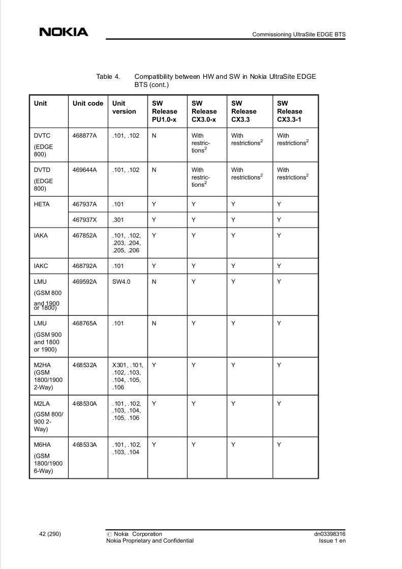
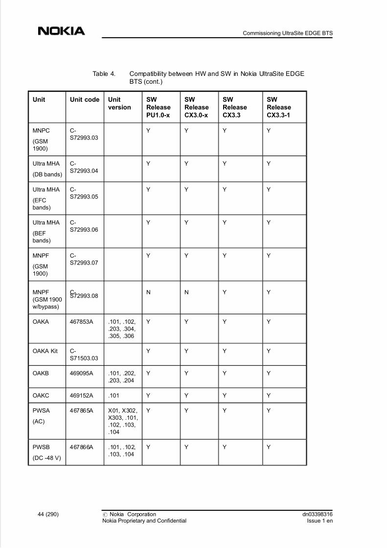
Table 4. Compatibility between HW and SW in Nokia UltraSite EDGE
BTS
Unit Unit code Unit
version
SW
Release
PU1.0-x
SW
Release
CX3.0-x
SW
Release
CX3.3
SW
Release
CX3.3-1
ACFU 468755A .101, .203,.204, .205 Y Y Y Y
ADUA C-
S71506.02
Y Y Y Y
ATCA 468686A .101, .102 Y Y Y Y
BATA C-
S71505.02
Y Y Y Y
dn03398316Issue 1 en
# Nokia CorporationNokia Proprietary and Confidential
39 (290)
Using Site Wizard commissioning software

5/14/2018 Commissioning Ultrasite EDGE BTS - slidepdf.com
http://slidepdf.com/reader/full/commissioning-ultrasite-edge-bts 40/290
Table 4. Compatibility between HW and SW in Nokia UltraSite EDGE
BTS (cont.)
Unit Unit code Unit
version
SW
Release
PU1.0-x
SW
Release
CX3.0-x
SW
Release
CX3.3
SW
Release
CX3.3-1
BBAG C-
S70403.00
Y Y Y Y
BB2A 467869A .103, .104,
.105, .106,
.1073
Y Y Y Y
BB2E 468131A .101, .202 N Y Y Y
BB2F 469643A X02, X03,
X04, .101
N N Y Y
BOIA 467868A .102, .103,
.104, .105,
.106
Y Y Y Y
BPDN
(GSM
800-1900)
C-
S72994.01
Y Y Y Y
BPDV
(GSM
1800/1900
W/VSWR)
C-
S72994.03
Y Y Y Y
BPGV
(GSM 800/
900 W/
VSWR)
C-
S72994.02
Y Y Y Y
CCUA C-
S71508.02
Y Y Y Y
CRMA 467851A X53, X54 Withrestric-
tions1
Withrestric-
tions1
Withrestrictions1
Withrestrictions1
.101, .102,
.103, .204, .
205, .206,
.207, .208
Y Y Y Y
40 (290) # Nokia CorporationNokia Proprietary and Confidential
dn03398316Issue 1 en
Commissioning UltraSite EDGE BTS

5/14/2018 Commissioning Ultrasite EDGE BTS - slidepdf.com
http://slidepdf.com/reader/full/commissioning-ultrasite-edge-bts 41/290
Table 4. Compatibility between HW and SW in Nokia UltraSite EDGE
BTS (cont.)
Unit Unit code Unit
version
SW
Release
PU1.0-x
SW
Release
CX3.0-x
SW
Release
CX3.3
SW
Release
CX3.3-1
CRMB 468080A X52, X53,
X54, X55,
.101, .102,
.103
Y Y Y Y
CRMC 468126A X301, .101,
.102
Y Y Y Y
DU2A 467812A .101 With
restric-
tions1
With
restric-
tions1
With
restrictions1With
restrictions1
DVDA
(GSM
1800)
468219A .101, .102,
.103, .104
Y Y Y Y
DVDB
(GSM
1800)
468220A .101, .102,
.103, .104
Y Y Y Y
DVDC
(GSM
1800)
468619A X11, .101,
.102
Y Y Y Y
DVGA
(GSM 900)
468216A .101, .102 Y Y Y Y
DVHA
(GSM 900)
468217A X21, .101,
.102
Y Y Y Y
DVJA
(GSM 900)
468218A X12, .101,
.102
Y Y Y Y
DVPA
(GSM
1900)
468221A .101, .102 Y Y Y Y
DVTB
(EDGE
800)
468133A .101, .102 N With
restric-
tions2
With
restrictions2With
restrictions21
dn03398316Issue 1 en
# Nokia CorporationNokia Proprietary and Confidential
41 (290)
Using Site Wizard commissioning software
5/14/2018 Commissioning Ultrasite EDGE BTS - slidepdf.com
http://slidepdf.com/reader/full/commissioning-ultrasite-edge-bts 42/290
Table 4. Compatibility between HW and SW in Nokia UltraSite EDGE
BTS (cont.)
Unit Unit code Unit
version
SW
Release
PU1.0-x
SW
Release
CX3.0-x
SW
Release
CX3.3
SW
Release
CX3.3-1
DVTC
(EDGE
800)
468877A .101, .102 N With
restric-
tions2
With
restrictions2With
restrictions2
DVTD
(EDGE
800)
469644A .101, .102 N With
restric-
tions2
With
restrictions2With
restrictions2
HETA 467937A .101 Y Y Y Y
467937X .301 Y Y Y Y
IAKA 467852A .101, .102,
.203, .204,
.205, .206
Y Y Y Y
IAKC 468792A .101 Y Y Y Y
LMU
(GSM 800
and 1900or 1800)
469592A SW4.0 N Y Y Y
LMU
(GSM 900
and 1800
or 1900)
468765A .101 N Y Y Y
M2HA
(GSM
1800/1900
2-Way)
468532A X301, .101,
.102, .103,
.104, .105,
.106
Y Y Y Y
M2LA
(GSM 800/
900 2-
Way)
468530A .101, .102,.103, .104,
.105, .106
Y Y Y Y
M6HA
(GSM
1800/1900
6-Way)
468533A .101, .102,
.103, .104
Y Y Y Y
42 (290) # Nokia CorporationNokia Proprietary and Confidential
dn03398316Issue 1 en
Commissioning UltraSite EDGE BTS

5/14/2018 Commissioning Ultrasite EDGE BTS - slidepdf.com
http://slidepdf.com/reader/full/commissioning-ultrasite-edge-bts 43/290
Table 4. Compatibility between HW and SW in Nokia UltraSite EDGE
BTS (cont.)
Unit Unit code Unit
version
SW
Release
PU1.0-x
SW
Release
CX3.0-x
SW
Release
CX3.3
SW
Release
CX3.3-1
M6LA
(GSM 800/
900 6-
Way)
468531A .101, .102,
.103, .104
Y Y Y Y
MNGA
(GSM 900)
C-
S72991.01
Y Y Y Y
MNTB
(EDGE
800 R)
C-
S72991.02
N With
restric-
tions2
With
restrictions2With
restrictions2
MNTC
(EDGE
800)
C-
S72991.03
N With
restric-
tions2
With
restrictions2With
restrictions2
MNTB
(EDGE
800 M)
C-
S72991.04
N With
restric-
tions2
With
restrictions2With
restrictions2
MNDA
(GSM
1800)
C-
S72992.01
Y Y Y Y
Ultra MHA
(GSM 1800
high band)
C-
S72992.02
Y Y Y Y
Ultra MHA
(GSM 1800
low band)
C-
S72992.03
Y Y Y Y
MNPA
(GSM
1900)
C-
S72993.01
Y Y Y Y
MNPB
(GSM
1900)
C-
S72993.02
Y Y Y Y
dn03398316Issue 1 en
# Nokia CorporationNokia Proprietary and Confidential
43 (290)
Using Site Wizard commissioning software
5/14/2018 Commissioning Ultrasite EDGE BTS - slidepdf.com
http://slidepdf.com/reader/full/commissioning-ultrasite-edge-bts 44/290
Table 4. Compatibility between HW and SW in Nokia UltraSite EDGE
BTS (cont.)
Unit Unit code Unit
version
SW
Release
PU1.0-x
SW
Release
CX3.0-x
SW
Release
CX3.3
SW
Release
CX3.3-1
MNPC
(GSM
1900)
C-
S72993.03
Y Y Y Y
Ultra MHA
(DB bands)
C-
S72993.04
Y Y Y Y
Ultra MHA
(EFC
bands)
C-
S72993.05
Y Y Y Y
Ultra MHA
(BEF
bands)
C-
S72993.06
Y Y Y Y
MNPF
(GSM
1900)
C-
S72993.07
Y Y Y Y
MNPF
(GSM 1900
w/bypass)
C-S72993.08
N N Y Y
OAKA 467853A .101, .102,
.203, .304,
.305, .306
Y Y Y Y
OAKA Kit C-
S71503.03
Y Y Y Y
OAKB 469095A .101, .202,
.203, .204
Y Y Y Y
OAKC 469152A .101 Y Y Y Y
PWSA
(AC)
467865A X01, X302,
X303, .101,
.102, .103,
.104
Y Y Y Y
PWSB
(DC -48 V)
467866A .101, .102,
.103, .104
Y Y Y Y
44 (290) # Nokia CorporationNokia Proprietary and Confidential
dn03398316Issue 1 en
Commissioning UltraSite EDGE BTS

5/14/2018 Commissioning Ultrasite EDGE BTS - slidepdf.com
http://slidepdf.com/reader/full/commissioning-ultrasite-edge-bts 45/290
Table 4. Compatibility between HW and SW in Nokia UltraSite EDGE
BTS (cont.)
Unit Unit code Unit
version
SW
Release
PU1.0-x
SW
Release
CX3.0-x
SW
Release
CX3.3
SW
Release
CX3.3-1
PWSC
(DC +24 V)
468664A .101, .102,
.104
N Y Y Y
RTDA
(GSM
1800)
467858A .102 Y Y Y Y
RTDB
(GSM
1800)
467859A .102 Y Y Y Y
RTDC
(GSM
1800)
468721A .101 With
restric-
tions1
With
restric-
tions1
With
restrictions1With
restrictions1
RTGA
(GSM 900)
467857A .102 Y Y Y Y
RTHA
(GSM 900)
467861A .101, .102 With
restric-
tions1
With
restric-
tions1
With
restrictions1With
restrictions1
RTJA
(GSM 900)
467862A .101, .102 With
restric-
tions1
With
restric-
tions1
With
restrictions1With
restrictions1
RTPA
(GSM
1900)
467860A .102 Y Y Y Y
TSDA
(GSM
1800)
467828A .101, .102,
.104, .105,
.105A,
.106, .107,
.108, .109,
.110
Y Y Y Y
dn03398316Issue 1 en
# Nokia CorporationNokia Proprietary and Confidential
45 (290)
Using Site Wizard commissioning software

5/14/2018 Commissioning Ultrasite EDGE BTS - slidepdf.com
http://slidepdf.com/reader/full/commissioning-ultrasite-edge-bts 46/290
Table 4. Compatibility between HW and SW in Nokia UltraSite EDGE
BTS (cont.)
Unit Unit code Unit
version
SW
Release
PU1.0-x
SW
Release
CX3.0-x
SW
Release
CX3.3
SW
Release
CX3.3-1
TSDB
(EDGE
1800)
468705A X55 N Y Y Y
469089A X44, X46,
X48, X64,
X65, X67,
X69, .101,
.102, .103,
.104, .105
N Y Y Y
TSDC
(GSM
1800)
469065A X41 N N N Y
TSGA
(GSM 900)
467800A .102, .104,
.105, .106,
.107, .108,
.109
Y Y Y Y
TSGB
(EDGE
900)
468704A .102, .103,
.104, .105
N Y Y Y
TSPA
(GSM
1900)
467829A .101, .103,
.104, .105,
.106
Y Y Y Y
TSPB
(EDGE
1900)
468706A X51, X57,
X64, X65,
X71, X73,
X2C, X4B,
.101, .102,
.103, .104,
.105, .106
N Y Y Y
TSPC
(GSM
1900)
469066A X32 N N N Y
TSTB
(EDGE
800)
469087A X56, X59,
X63, X64,
X81, X3G,
.101, .102,
.103, .104,
.105, .106
N With
restric-
tions2
With
restrictions2With
restrictions2
46 (290) # Nokia CorporationNokia Proprietary and Confidential
dn03398316Issue 1 en
Commissioning UltraSite EDGE BTS

5/14/2018 Commissioning Ultrasite EDGE BTS - slidepdf.com
http://slidepdf.com/reader/full/commissioning-ultrasite-edge-bts 47/290
Table 4. Compatibility between HW and SW in Nokia UltraSite EDGE
BTS (cont.)
Unit Unit code Unit
version
SW
Release
PU1.0-x
SW
Release
CX3.0-x
SW
Release
CX3.3
SW
Release
CX3.3-1
TSTC
(GSM 800)
469063A X34 N N N Y
UABA 469107A .101 Y Y Y Y
VXEA
(FC E1/T1)
467201A .101, .102 With
restric-
tions1
With
restric-
tions1
With
restrictions1With
restrictions1
.103 Y Y Y Y
VXRB
(FXC RRI)
467610A X044 With
restric-
tions1
With
restric-
tions1
With
restrictions1With
restrictions1
.101, .102,
.103, .1044Y Y Y Y
VXTA
(FXC E1)
467612A X064 With
restric-
tions1
With
restric-
tions1
With
restrictions1With
restrictions1
X07, .101,
.102, .103,
.1044
Y Y Y Y
VXTB
(FXC E1/
T1)
467611A X064 With
restric-
tions1
With
restric-
tions1
With
restrictions1With
restrictions1
X07, .101,
.102, .103,
.1044
Y Y Y Y
WCDA(GSM
1800)
467834A X31, .101,.102, .103
Y Y Y Y
WCGA
(GSM 800/
900)
467833A X31, .101,
.102
Y Y Y Y
WCPA
(GSM
1900)
467835A .101, .102 Y Y Y
dn03398316Issue 1 en
# Nokia CorporationNokia Proprietary and Confidential
47 (290)
Using Site Wizard commissioning software

5/14/2018 Commissioning Ultrasite EDGE BTS - slidepdf.com
http://slidepdf.com/reader/full/commissioning-ultrasite-edge-bts 48/290
Y = Compatible
N = Not compatible
1There are no compatibility problems detected. However, the compatibility is not
properly tested.
2EDGE 800 requires BSC SW version S10.
3PU1.0-2 SW or newer required for .107.
4For more detailed information about transmission unit hardware and software
compatibility, refer to ITN hardware and software compatibility and ITN
compatibility in BSS transmission networks.
6.3.2 Compatibility between BTS, SiteWizard, BSC, NMS/2000/NetAct andLMU software
Table 5. Compatibility between BTS, SiteWizard and BSC SW versions
BTS
SW
Site
Wizard
BSC SW
S9 S10 S10.5 S10.5ED
PU1.0 2.01 Y Y Y N
PU1.0-1 2.01 update Y Y Y N
PU1.0-2 2.1 Y Y Y N
PU1.0-3 2.1 Y Y Y N
PU1.0-4 2.1 Y Y Y N
PU1E
(-1, -2)
3.0 Y Y2 Y N
CX3L
(-1, -2)
3.0 Y Y Y N
CX3.0
(-1, -2, -
2A)
3.0 Y2 Y3 Y N
CX3.0-3 3.0 Y2 Y3 Y Y
48 (290) # Nokia CorporationNokia Proprietary and Confidential
dn03398316Issue 1 en
Commissioning UltraSite EDGE BTS

5/14/2018 Commissioning Ultrasite EDGE BTS - slidepdf.com
http://slidepdf.com/reader/full/commissioning-ultrasite-edge-bts 49/290
Table 5. Compatibility between BTS, SiteWizard and BSC SW versions (cont.)
BTS
SW
Site
Wizard
BSC SW
S9 S10 S10.5 S10.5ED
CX3.3 3.04 N N Y Y
CX3.3-1 3.0 Y Y Y Y
Y = Compatible
N = Not compatible
1SiteWizard 2.0 is also compatible with PU1.0-2.
2BSS10 level features cannot be used.
3BSC SW S10 does not support Support of PCCCH/PBCCH and GSM-
WCDMA Interworking.
4SiteWizard 3.0 with BTS Manager 3.3 and BTS HW Configurator 3.3.
Table 6. Compatibility between BTS, SiteWizard, NMS/2000/NetAct andLMU SW versions
BTS
SW
Site
Wizard
NMS 2000/NetAct SW LMU
SW
T12 OSS
3.1
OSS
3.1
ED1
OSS
3.1
ED2
LMU1
PU1.0 2.01 Y Y N N N
PU1.0-1 2.01 update Y Y N N N
PU1.0-2 2.1 Y Y N N N
PU1.0-3 2.1 Y Y N N N
PU1.0-4 2.1 Y Y N N N
PU1E
(-1, -2)
3.0 Y Y N N N
dn03398316Issue 1 en
# Nokia CorporationNokia Proprietary and Confidential
49 (290)
Using Site Wizard commissioning software

5/14/2018 Commissioning Ultrasite EDGE BTS - slidepdf.com
http://slidepdf.com/reader/full/commissioning-ultrasite-edge-bts 50/290
Table 6. Compatibility between BTS, SiteWizard, NMS/2000/NetAct and
LMU SW versions (cont.)
BTS
SW
Site
Wizard
NMS 2000/NetAct SW LMU
SW
T12 OSS
3.1
OSS
3.1
ED1
OSS
3.1
ED2
LMU1
CX3L
(-1, -2)
3.0 Y Y N N Y
CX3.0
(-1, -2, -
2A)
3.0 Y Y Y N Y
CX3.0-3 3.0 Y Y Y Y Y
CX3.3 3.02 Y N Y Y Y
CX3.3-1 3.0 Y Y Y Y Y
Y = Compatible
N = Not compatible
1SiteWizard 2.0 is also compatible with PU1.0-2.
2SiteWizard 3.0 with BTS Manager 3.3 and BTS HW Configurator 3.3.
6.3.3 Compatibility between new features of UltraSite EDGE BTS softwarerelease CX3.3 and other network elements
Table 7. Compatibility between new features of CX3.3 and other network
elements
New BSS10.5 features that are standard in BTS BSC SW NMS SW
Enhanced General Packet Radio Service (MCS 1-9) S10.5 ED OSS3.1
Dynamic Abis allocation S10.5 ED OSS3.1
Incremental Redundancy (IR) S10.5 ED OSS3.1
50 (290) # Nokia CorporationNokia Proprietary and Confidential
dn03398316Issue 1 en
Commissioning UltraSite EDGE BTS

5/14/2018 Commissioning Ultrasite EDGE BTS - slidepdf.com
http://slidepdf.com/reader/full/commissioning-ultrasite-edge-bts 51/290
Table 7. Compatibility between new features of CX3.3 and other network
elements (cont.)
New BSS10.5 features that are standard in BTS BSC SW NMS SW
Link Adaptation (LA) S10.5 ED OSS3.1
Remote BTS Manager S10.5
S10.5 ED
T12
OSS3.1 (ED1, ED2)
6.4 ITN hardware and software compatibility
6.4.1 ITN versions
This section lists the FXC unit HW and SW versions when supplied from Nokia.
For information on older versions, contact Nokia technical support.
The FXC unit identification information can be viewed in the unit identifications
dialogue. The ITN C1.2 and earlier release FXC hardware product codes and
versions are not shown in the unit identification dialogue. However, linking to
HW may be done via the product code and version, visible in the unit
identifications dialogue and in the unit label. In release ITN C2.0 and later,
product HW, SW and boot code versions are shown in the identificationsdialogue. However, the compatibility between HW and SW is determined by the
ID information.
After upgrading an old FXC unit with ITN C2.1 software, Product version is
deleted. Compatibilities may be traced by using Product code and version for SW ,
Product code and version for HW , and Boot code and version.
Table 8. Versions for FXC E1, VXTA
Product codeand version
Product codeand version for
HW
Boot code andversion
Product codeand version for
SW
467612A.101 E36123.01-A0 S36124.01-03 S36122.01-A0
467612A.101 E36123.01-A0 S36124.01-03 S36122.01-A1
467612A.102 E36123.01-A0 S36124.01-03 S36122.01-A3
dn03398316Issue 1 en
# Nokia CorporationNokia Proprietary and Confidential
51 (290)
Using Site Wizard commissioning software

5/14/2018 Commissioning Ultrasite EDGE BTS - slidepdf.com
http://slidepdf.com/reader/full/commissioning-ultrasite-edge-bts 52/290
Table 8. Versions for FXC E1, VXTA (cont.)
Product code
and version
Product code
and version for
HW
Boot code and
version
Product code
and version for
SW
467612A.103 E36123.01-A0 S36124.01-03 S36122.01-B0
467612A.104 E36123.01-B0 S36124.01-A S36122.01-C0
467612A.105 E36123.01-E0 S36124.01-B S36122.01-D1
Table 9. Versions for FXC E1/T1, VXTB
Product code
and version
Product code
and version for
HW
Boot code and
version
Product code
and version for
SW
467611A.101 E36133.01-A0 S36124.01-03 S36122.01-A0
467611A.102 E36133.01-A0 S36124.01-03 S36122.01-A1
467611A.102 E36133.01-A0 S36124.01-03 S36122.01-A3
467611A.103 E36133.01-A0 S36124.01-03 S36122.01-B0
467611A.104 E36133.01-B0 S36124.01-A S36122.01-C0
467611A.105 E36133.01-E0 S36124.01-B S36122.01-D1
Table 10. Versions for FXC RRI, VXRB
Product code
and version
Product code
and version for
HW
Boot code and
version
Product code
and version for
SW
467610A.101 E55833.01-A0 S55834.01-A S55832.01-B1
467610A.103 E55833.01-A1 S55834.01-A S55832.01-C0
467610A.104 E55833.01-B0 S55834.01-B S55832.01-D0
467610A.105 E55833.01-C0 S55834.01-C S55837.01-A
52 (290) # Nokia CorporationNokia Proprietary and Confidential
dn03398316Issue 1 en
Commissioning UltraSite EDGE BTS

5/14/2018 Commissioning Ultrasite EDGE BTS - slidepdf.com
http://slidepdf.com/reader/full/commissioning-ultrasite-edge-bts 53/290
6.4.2 ITN HW compatibility
All the FXC HW versions mentioned in ITN versions are compatible with
UltraSite EDGE BTS, MetroSite EDGE BTS and MetroHub cabinets.
6.4.3 ITN HW/SW compatibility
Table 11. HW/SW compatibility for FXC E1, VXTA and FXC E1/T1, VXTB
Product code and
version for SW
Boot code and version
S36124.01-03 S36124.01-A S36124.01-B
S36122.01-A0 Yes No No
S36122.01-A1 Yes No No
S36122.01-A3 Yes No No
S36122.01-B0 Yes No No
S36122.01-C0 Yes Yes No
S36122.01-D1 Yes Yes Yes
Table 12. HW/SW compatibility for FXC RRI, VXRB
Product code and
version for SW
Boot code and version
S55834.01-A S55834.01-B S55834.01-C
S55832.01-B1 Yes Yes No
S55832.01-C0 Yes Yes No
S55832.01-D0 Yes Yes No
S55832.01-E0 Yes Yes No
S55837.01-A0 No No Yes
dn03398316Issue 1 en
# Nokia CorporationNokia Proprietary and Confidential
53 (290)
Using Site Wizard commissioning software

5/14/2018 Commissioning Ultrasite EDGE BTS - slidepdf.com
http://slidepdf.com/reader/full/commissioning-ultrasite-edge-bts 54/290
6.5 ITN compatibility in BSS transmission networks
SiteWizard
The node managers are delivered as a part of the Nokia SiteWizard Release C3.1.
ITN C2.1 is compatible only with SiteWizard 3.1.
BTS SW
The ITN C2.1 release supports the following BTS software releases:
. MetroSite EDGE BTS
- CXM3.0 and later releases
- C3.3 and later releases
. UltraSite EDGE BTS
- CX3.0 and later releases
- CX3.3 and later releases
Microwave radios
Table 13. Radio software releases compatible with ITN C2.1
Nokia MetroHopper P55820.01-B0, -C0, -D1, -E0
Nokia FlexiHopper P55040.01-F0,-G1, -H0, -
H1
P55046.01-B0, -C0, -C1, -
D0, -E0, -E1
Nokia FlexiHopper Plus P58040.01 (limited verification)
Note
Nokia FlexiHopper Plus is released after ITN C2.1 and thus only limited
verification.
54 (290) # Nokia CorporationNokia Proprietary and Confidential
dn03398316Issue 1 en
Commissioning UltraSite EDGE BTS

5/14/2018 Commissioning Ultrasite EDGE BTS - slidepdf.com
http://slidepdf.com/reader/full/commissioning-ultrasite-edge-bts 55/290
Network
Table 14. Network management systems compatible with ITN C2.1
BSC S10.5 and later releases
NMS OSS 3.1ED1 and later releases
NMS/10 SR5.1
C5.2
C6.0
ITN releases
ITN C2.1 is compatible with both ITN release C1.2 and ITN release C2.0 within
the same network, however, not within one node.
FC units
Table 15. FC units supported in the ITN C2.1 release
Unit Hardware version Software version
FC E1/T1, VXEA 467201A.102
467201A.103/104
B1, C0 or C1
C0 or C1
Note
ITN C2.1 is compatible with FC units within the same network, however, not
within one node.
Other transmission units
Table 16. Other transmission units supported in the ITN C2.1 release
Unit Version Software version
dn03398316Issue 1 en
# Nokia CorporationNokia Proprietary and Confidential
55 (290)
Using Site Wizard commissioning software

5/14/2018 Commissioning Ultrasite EDGE BTS - slidepdf.com
http://slidepdf.com/reader/full/commissioning-ultrasite-edge-bts 56/290
Table 16. Other transmission units supported in the ITN C2.1 release (cont.)
FIU 19 T55240.xx-B
T55240.xx-C
P55234.01-B3, -C1, -D0, -
F0, -F1
P55234.01-B3, -C1, -D0, -
F0, -F1
FIU 19E T55340.01-C0 P55303.01-C0
RRIC T55290.01-B1
T55290.01-C0... -C3
P55298.01-C2
P55285.01-B2
Note
Where the version includes xx as in T55240.xx B, the xx refers to many different
product versions.
56 (290) # Nokia CorporationNokia Proprietary and Confidential
dn03398316Issue 1 en
Commissioning UltraSite EDGE BTS

5/14/2018 Commissioning Ultrasite EDGE BTS - slidepdf.com
http://slidepdf.com/reader/full/commissioning-ultrasite-edge-bts 57/290
7 Commissioning GSM/EDGE UltraSite
EDGE BTS
7.1 Overview of commissioning GSM/EDGE UltraSite
EDGE BTS
Before you start
Review the Overview of commissioning UltraSite EDGE BTS . Pay careful
attention to all Warnings and Cautions.
Note
It is necessary to connect a Frequency counter to the BOI 13 MHz test port and
power on the frequency counter before beginning the commissioning procedure.This enables the counter timer to warm up and thus get accurate measurements.
Summary
Nokia UltraSite EDGE BTS is manually commissioned, using these Nokia
software applications:
. BTS HW Configurator - a tool for creating, checking, and updating the
configuration of an UltraSite EDGE BTS cabinet.
. BTS Hub Manager - a tool for configuring and testing the transmission of
the BTS and its Hub node (if there are FxC units in the configuration).
. BTS Manager - a tool for configuring, commissioning and managing
UltraSite EDGE BTS and related transmission equipment. BTS
Commissioning Wizard is included in BTS Manager (includes FC E1/T1
transmission unit configuration).
dn03398316Issue 1 en
# Nokia CorporationNokia Proprietary and Confidential
57 (290)
Commissioning GSM/EDGE UltraSite EDGE BTS

5/14/2018 Commissioning Ultrasite EDGE BTS - slidepdf.com
http://slidepdf.com/reader/full/commissioning-ultrasite-edge-bts 58/290
Note
Only one application can be communicating with the BTS at a time. Close BTS
HW Configurator before starting UltraSite BTS Hub Manager, and close HubManager before starting BTS Manager.
Nokia BTS Manager and related UltraSite BTS Hub manager software have a
convenient, context-sensitive online Help facility.
To get help, do one of the following:
. press F1
. click the Help button on the toolbar
. choose one of the Help menu commands
. click the Help button in any dialog box
To exit Help, press ESC or ALT+F4.
The Help Topics window displays a set of tabbed pages:
. Contents - displays a list of topics organized in books by category.
. Index - lists keywords in alphabetical order through which different topicscan be reached.
. Find - provides a full-text search functionality that allows you to search for
any word or phrase in the Help file.
Readers should note that all images in this document are typical in nature and are
for general reference only. For hardware, the versions depicted may differ from
the latest version of equipment. For software, any version numbers shown in any
of the windows/screens/dialog boxes may not be the same as the actual software
that is to be installed. It is important to remember that the procedure steps must be
followed, as these will give advice on the correct software to be installed and the
correct text that will be displayed in each window/screen/dialog box.
Steps
1. Define the BTS configuration with Nokia BTS HW Configurator.
58 (290) # Nokia CorporationNokia Proprietary and Confidential
dn03398316Issue 1 en
Commissioning UltraSite EDGE BTS

5/14/2018 Commissioning Ultrasite EDGE BTS - slidepdf.com
http://slidepdf.com/reader/full/commissioning-ultrasite-edge-bts 59/290
Nokia BTS HW Configurator allows you to use an existing configuration
or to create a new configuration, if there is no pre-defined hardware
configuration file available for the BTS. A BTS HW configuration file
with basic UltraSite BTS configurations is delivered with Nokia BTS HW
Configurator. You may use the default parameters or modify them as
necessary.
2. Commission the FXC transmission units with Nokia UltraSite BTS
Hub Manager.
The transmission of the BTS and its Hub node are configured and tested
during commissioning with Nokia UltraSite BTS Hub Manager . FXC
transmission units can be manually commissioned or commissioned based
on a node file. When commissioning based on a node file, send the node
file to the node during the commissioning procedure with the Nokia
UltraSite BTS Hub Commissioning Wizard. This allows more network setup to be done off-site.
Note
If the BTS configuration includes an FC E1/T1 transmission unit, that unit is
configured with the Commissioning Wizard in BTS Manager.
3. Commission the BTS with BTS Commissioning Wizard.
The BTS Commissioning Wizard guides you through the commissioning
tasks, including manual entry of commissioning parameters.
Commissioning Wizard runs automatic BSC-controlled tests and generates
the BTS Commissioning Report, which contains information collected
during the commissioning procedure. FC E1/T1 transmission units are
configured during this step.
Note
If the BTS is already commissioned, Undo Commissioning is the only option
available in the BTS Commissioning Wizard. Because the BTS can only be
commissioned in its non-commissioned state, this procedure is typically
necessary when the BTS has to be re-commissioned (for example, when it has
been commissioned with incorrect parameters). The Undo Commissioning
procedure clears previous commissioning data from the BTS.
dn03398316Issue 1 en
# Nokia CorporationNokia Proprietary and Confidential
59 (290)
Commissioning GSM/EDGE UltraSite EDGE BTS

5/14/2018 Commissioning Ultrasite EDGE BTS - slidepdf.com
http://slidepdf.com/reader/full/commissioning-ultrasite-edge-bts 60/290
7.2 Hub configuration of GSM/EDGE UltraSite EDGEBTS
7.2.1 Manual Hub configuration of UltraSite EDGE BTS
Summary
Caution
The Power On setting should not be used when two RRI units are connected with
a Flexbus cable. If power is on in such a case, the units could be damaged.
Steps
1. Open the Nokia UltraSite BTS Manager.
From the Nokia Applications submenu on the Start | Programs menu in
Windows, select Nokia UltraSite BTS Manager .
Wait until the BTS Manager has properly started and only then move to the
next step.
2. Start the Nokia UltraSite BTS Hub Manager.
Start Nokia UltraSite BTS Hub Manager from the BTS Manager's Tools
menu.
When the connection has been established, the Equipment view opens
automatically.
3. If the connection fails,
Then
Troubleshoot the connection.
Verify the connection speed and LMP cable connection from the Tools |
Options | Manager options. You can also try the Connection | Connect...
command and enter the connection parameters in the Connect to Node
window. Using the Nokia Connection Tool, refer to the applications online
Help.
4. Define LIF settings.
60 (290) # Nokia CorporationNokia Proprietary and Confidential
dn03398316Issue 1 en
Commissioning UltraSite EDGE BTS

5/14/2018 Commissioning Ultrasite EDGE BTS - slidepdf.com
http://slidepdf.com/reader/full/commissioning-ultrasite-edge-bts 61/290
a. Define FXC E1/T1 LIF settings.
b. Define FXC RR1 LIF settings.
5. Adjust identification settings.
6. Adjust service interface settings.
7. Configure radio units for FXC RRI units.
8. Adjust synchronisation settings.
9. Adjust synchronisation loop bit settings.
10. Adjust Q1 management settings.
11. Adjust alarm property settings .
12. Allocate transmission capacity.
13. Create bi-directional cross-connections.For more information about
cross-connections, see Overview of managing cross-connections.
14. Exit UltraSite BTS Hub Manager.
BTS Manager opens automatically if you started the UltraSite Hub
Manager from the BTS Manager.
7.2.2 Defining Line Interface (LIF) settings of UltraSite EDGE BTS FXC E1/ T1 units
Before you start
Review Manual Hub configuration of UltraSite EDGE BTS . Pay careful attention
to all Warnings and Cautions.
Note
The line interface (LIF) settings available for each transmission unit depend on
the type of the unit: FXC E1(/T1) or FXC RRI.
Steps
dn03398316Issue 1 en
# Nokia CorporationNokia Proprietary and Confidential
61 (290)
Commissioning GSM/EDGE UltraSite EDGE BTS

5/14/2018 Commissioning Ultrasite EDGE BTS - slidepdf.com
http://slidepdf.com/reader/full/commissioning-ultrasite-edge-bts 62/290
1. View unit-specific menu.
Click the appropriate FXC E1(/T1) unit in the Equipment view in Nokia
UltraSite BTS Hub Manager. A unit-specific menu displays on the menu bar.
2. Display unit-specific settings.
Select LIF Settings on the FXC E1/T1 menu. The LIF Settings window
displays.
3. Select the tab for the line interface you want (LIF 1 - LIF 4).
4. If the interface will be used,
Then
Select the Interface in Use option.
Else
If the interface is not in use,
a. Deselect this option and proceed to the settings of another interface
(step 3).
Note
Only when an interface is taken into use then alarms are reported for this interface
and performance data is collected.
5. Name the interface.
Type a name for the interface in the Interface Name field.
6. Select the mode.
Select the mode from the Interface Mode list.
7. If you selected the E1 75 ohm interface mode or the E1 120 ohm interface
mode,
Then
62 (290) # Nokia CorporationNokia Proprietary and Confidential
dn03398316Issue 1 en
Commissioning UltraSite EDGE BTS

5/14/2018 Commissioning Ultrasite EDGE BTS - slidepdf.com
http://slidepdf.com/reader/full/commissioning-ultrasite-edge-bts 63/290
Define TS0 fixed bits in the LIF Settings window for E1 120 ohm mode
. Only bits 4 - 8 can be modified, as bits 1 - 3 are reserved for CRC,
frame alighnment and far end alarm indication.
Select the CRC in Use option if an E1 signal in multiframe mode is used.
When using an E1 basic (double) frame, then the CRC in Use option
should be de-selected (no checkmark in box).
8. If you selected the T1 100 ohm interface mode,
Then
Define the Framing Format, Line Code and T1 Interface Type settings
in LIF Settings window for T1 100 ohm mode .
9. Accept the changes.
Click Apply button to accept the changes for the selected LIF tab. The
Apply button is disabled if you made no changes.
10. If necessary, verify or modify the settings for the other line interfaces
as described in steps 1 through 9.
11. Click OK to accept the changes.
12. Repeat steps 1 through 11 for all other FXC E1(/T1) transmission
units in the configuration.
7.2.3 Defining Line Interface (LIF) settings of UltraSite EDGE BTS FXC RRIunits
Before you start
Review Manual Hub configuration of UltraSite EDGE BTS . Pay careful attention
to all Warnings and Cautions.
Note
The line interface settings available for each transmission unit depend on the type
of the unit: FXC E1(/T1) or FXC RRI.
Steps
dn03398316Issue 1 en
# Nokia CorporationNokia Proprietary and Confidential
63 (290)
Commissioning GSM/EDGE UltraSite EDGE BTS

5/14/2018 Commissioning Ultrasite EDGE BTS - slidepdf.com
http://slidepdf.com/reader/full/commissioning-ultrasite-edge-bts 64/290
1. View unit-specific menu.
Click the appropriate FXC RRI unit in the Equipment view in Nokia
UltraSite BTS Hub Manager. A unit-specific menu displays on the menu bar.
2. Display unit-specific settings.
Select the Settings | Unit command on the FXC RRI menu. The Settings
window displays.
3. Select either the FlexBus interface to be configured or the platform
interfaces.
The Platform interfaces are E1 interfaces connecting the radio/FlexBus part
of the FXC RRI unit to the transmission node. There are 16 platform
interfaces available per unit.
4. If the interface will be used,
Then
Select the In Use option.
Else
If the interface is not in use, deselect this option and proceed to the
settings of another interface (step 3).
5. Select the capacity for the interface.
In the Capacity field, select from 2 x 2Mb to 16 x 2Mb.
Select the capicity according to the capacity of the Microwave radio link
connected to a particular FlexBus interface.
6. If the RRI unit is directly connected to an outdoor unit (radio),
Then
Select the Power On option.
Caution
The Power On setting should not be used when two RRI units are connected with
a Flexbus cable. If power is on in such a case, the units could be damaged.
64 (290) # Nokia CorporationNokia Proprietary and Confidential
dn03398316Issue 1 en
Commissioning UltraSite EDGE BTS
5/14/2018 Commissioning Ultrasite EDGE BTS - slidepdf.com
http://slidepdf.com/reader/full/commissioning-ultrasite-edge-bts 65/290
7. Accept the changes.
Click Apply to accept the changes for the selected interface tab. The Apply
button is disabled if you made no changes.
8. If necessary, verify or modify the settings for the other Flexbus
interface as described in steps 1 through 7.
9. Define settings for platform interfaces.
a. Click the Platform Interface tab to display a list of platform
interfaces.
b. Right-click a platform interface.
c. Select the appropriate commands from the pop-up menu (Interface
in Use, CRC in Use).
10. Click OK to accept the changes.
11. Repeat steps 1 through 10 for all other FXC RRI units in the
configuration.
7.2.4 Adjusting identification settings
Purpose
You can adjust the identification settings for the managed node using the
Hardware Identifications dialogue. The user can fill in the name, site name,
group name and site location, and these are valid for the whole node.
Summary
Identification-related settings are not mandatory but it is strongly recommended
to use them. The settings are:
. Node ID (equipment name and site name)
.
Transmission unit names and installation dates (in the correspondingtransmission unit menu)
Note
If you change the master FXC unit of the node, all User Notes are lost. Other
identification settings do not disappear.
dn03398316Issue 1 en
# Nokia CorporationNokia Proprietary and Confidential
65 (290)
Commissioning GSM/EDGE UltraSite EDGE BTS

5/14/2018 Commissioning Ultrasite EDGE BTS - slidepdf.com
http://slidepdf.com/reader/full/commissioning-ultrasite-edge-bts 66/290
Steps
1. Connect to the node or open a file
2. Select Configuration Identifications...
The Hardware Identifications dialogue opens.
Figure 5. Hardware Identifications dialogue
3. Select which identifications data you want to adjust, fill in the required
information and click OK
7.2.5 Adjusting service interface settings
Summary
You can adjust the settings of the LMP and the Q1 port. The settings are baud
rate, Q1 address and Q1 group address. It is also possible to adjust timeouts under
this menu.
66 (290) # Nokia CorporationNokia Proprietary and Confidential
dn03398316Issue 1 en
Commissioning UltraSite EDGE BTS

5/14/2018 Commissioning Ultrasite EDGE BTS - slidepdf.com
http://slidepdf.com/reader/full/commissioning-ultrasite-edge-bts 67/290
The timeout settings concern the temporary settings of the whole node. These
include, for example, interface loops and forced controls.
Steps
1. Connect to the node or open a file
2. Select Configuration Service Interface...
Expected outcome
The Service Interface dialogue opens.
Figure 6. Service Interface dialogue
3. Select either Port Settings or Timeouts
4. Adjust the settings
The supported baud rates for LMP are 9600 115 200 bit/s.
Supported remote Q1 connection rates are 24009600 bit/s.
The default baud rate is 2400 bit/s for Q1 and 9600 for LMP. The default
address is 1 for the ports.
The Default buttons in the Timeouts tab set the default values stored in the
node.
dn03398316Issue 1 en
# Nokia CorporationNokia Proprietary and Confidential
67 (290)
Commissioning GSM/EDGE UltraSite EDGE BTS
5/14/2018 Commissioning Ultrasite EDGE BTS - slidepdf.com
http://slidepdf.com/reader/full/commissioning-ultrasite-edge-bts 68/290
7.2.6 Configuring radio units for FXC RRI units of UltraSite EDGE BTS
Before you start
This section describes how to configure the radio settings using the Radio
Wizard. This is an alternative approach to the manual configuration described in
Chapter Obligatory radio settings. For more information on the commissioning
and maintenance of the radio units, refer to Nokia MetroHopper and FlexiHopper
user manuals.
If there are no FXC RRI units in the configuration, proceed directly to Section
Synchronisation.
Summary
To configure outdoor units:
Steps
1. Click a FXC RRI transmission unit in the Equipment view in UltraSite
BTS Hub Manager.
2. Select Radio Wizard on the FXC RRI menu to launch the Wizard.
The Radio Wizard is launched from the Nokia RRI Manager application.
3. The Flexbus Settings page displays the type of the indoor unit and theoutdoor units connected to each Flexbus.
The parameters displayed are dependent on the operation mode (HSB/
Single Hop) selected for RRI unit. See Figure Flexbus settings page with
HSB activated and Figure Flexbus settings page with Flexihopper (single
mode) and MetroHopper outdoor units. For more information on operation
mode, see sectionTraffic Protection in Nokia MetroHub Product
Description.
Note
The HSB mode can be configured only when both Flexbuses of the FXC RRI
unit have Flexihopper radios connected to them.
68 (290) # Nokia CorporationNokia Proprietary and Confidential
dn03398316Issue 1 en
Commissioning UltraSite EDGE BTS

5/14/2018 Commissioning Ultrasite EDGE BTS - slidepdf.com
http://slidepdf.com/reader/full/commissioning-ultrasite-edge-bts 69/290
Figure 7. Flexbus settings page with HSB activated
4. Select the capacity for each outdoor unit from the Capacity drop-down
list and select the Commission the unit and In Use option for each
Flexbus you want to use. At least one outdoor unit must exist and be
selected for commissioning (Commission the unit), before you can
continue to the next Wizard page.
You can deselect the Commission the Unit option for a Flexbus, if you
want to skip the commissioning of a radio for some reason (for example,
far end not ready).
Note
With Nokia MetroHopper outdoor unit, the capacity is fixed to 4 x 2 Mbit/s.
5. Click Next to continue.
dn03398316Issue 1 en
# Nokia CorporationNokia Proprietary and Confidential
69 (290)
Commissioning GSM/EDGE UltraSite EDGE BTS

5/14/2018 Commissioning Ultrasite EDGE BTS - slidepdf.com
http://slidepdf.com/reader/full/commissioning-ultrasite-edge-bts 70/290
Figure 8. Flexbus settings page with Flexihopper (single mode) and
MetroHopper outdoor units
Note
Bandwidth selection is available only with the FlexiHopper and outdoor unit.
The Flexbus 1 - FlexiHopper Settings page opens on the screen. The
options on the page depend on the type of the outdoor unit connected to the
interface. The settings for the FlexiHopper outdoor unit are presented in
the following figure:
70 (290) # Nokia CorporationNokia Proprietary and Confidential
dn03398316Issue 1 en
Commissioning UltraSite EDGE BTS
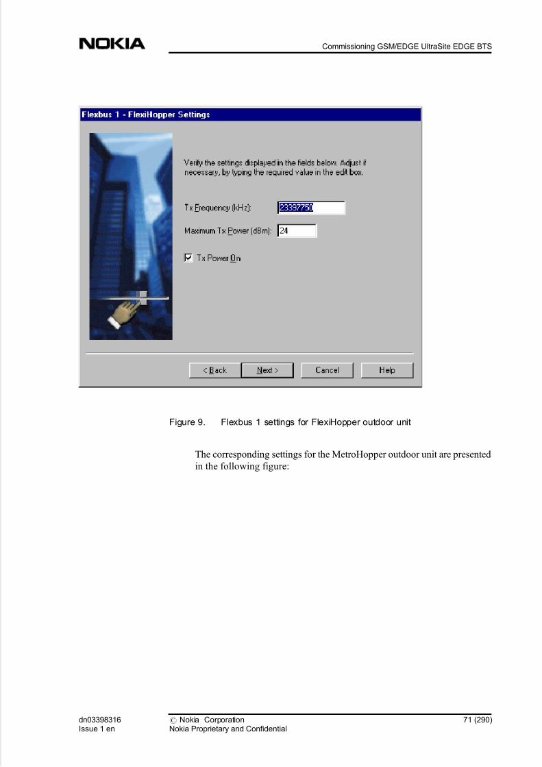
5/14/2018 Commissioning Ultrasite EDGE BTS - slidepdf.com
http://slidepdf.com/reader/full/commissioning-ultrasite-edge-bts 71/290
Figure 9. Flexbus 1 settings for FlexiHopper outdoor unit
The corresponding settings for the MetroHopper outdoor unit are presented
in the following figure:
dn03398316Issue 1 en
# Nokia CorporationNokia Proprietary and Confidential
71 (290)
Commissioning GSM/EDGE UltraSite EDGE BTS

5/14/2018 Commissioning Ultrasite EDGE BTS - slidepdf.com
http://slidepdf.com/reader/full/commissioning-ultrasite-edge-bts 72/290
Figure 10. Flexbus 2 settings for MetroHopper outdoor unit
Note
The Temporary Hop ID on the MetroHopper General Settings page must be the
same for both the master and slave terminal.
6. Select either the Manual or Automatic option under Channel Selection
on the Flexbus 2 - MetroHopper General Settings page.
When you click Next, based upon the channel selection, either the Flexbus
2 - MetroHopper Manual Channel Selection page (see Figure
MetroHopper manual channel selection) or Flexbus 2 - MetroHopper
Automatic Channel Selection page (see Figure MetroHopper automatic
channel selection) opens.
a. If you selected Manual channel selection, select one channel to be
used. You can also click Measure to measure the signal strength of
the selected channels and then select the best channel.
Note
At least one channel must be selected, before you can continue to the next page.
72 (290) # Nokia CorporationNokia Proprietary and Confidential
dn03398316Issue 1 en
Commissioning UltraSite EDGE BTS

5/14/2018 Commissioning Ultrasite EDGE BTS - slidepdf.com
http://slidepdf.com/reader/full/commissioning-ultrasite-edge-bts 73/290
Figure 11. MetroHopper Manual Channel Selection
Note
At least one channel must be selected, before you can continue to the next page.
b. If you selected Automatic channel selection, the Wizard will
automatically scan the channels to find the far end radio. Click Next to continue.
dn03398316Issue 1 en
# Nokia CorporationNokia Proprietary and Confidential
73 (290)
Commissioning GSM/EDGE UltraSite EDGE BTS

5/14/2018 Commissioning Ultrasite EDGE BTS - slidepdf.com
http://slidepdf.com/reader/full/commissioning-ultrasite-edge-bts 74/290
Figure 12. MetroHopper Automatic Channel Selection
7. If the transmission unit type is FXC RRI, define the Flexbus 2 settings
for the outdoor unit as described in step 5. This is needed only if
Commission the unit option for Flexbus 2 was selected in the Flexbus
Settings page.
8. The Summary of Commissioning Settings page displays the settings
you have defined for commissioning the radio(s).
74 (290) # Nokia CorporationNokia Proprietary and Confidential
dn03398316Issue 1 en
Commissioning UltraSite EDGE BTS

5/14/2018 Commissioning Ultrasite EDGE BTS - slidepdf.com
http://slidepdf.com/reader/full/commissioning-ultrasite-edge-bts 75/290
Figure 13. Summary of Commissioning Settings
Check that the settings are correct and click Next to start the actual
commissioning procedure.
9. The Monitoring Hop page displays the status of the hops during and
after the commissioning.
The commissioning may take some time, and the Status field displays the
message 'reading status'.The status changes to 'Ready', if thecommissioning was successful. If the commissioning fails for some reason,
the Status field gives a short description of the failure (for example,
'Trying... no far end found'). If the commissioning still fails, refer to Nokia
MetroHopper and FlexiHopper user manuals for more information.
dn03398316Issue 1 en
# Nokia CorporationNokia Proprietary and Confidential
75 (290)
Commissioning GSM/EDGE UltraSite EDGE BTS

5/14/2018 Commissioning Ultrasite EDGE BTS - slidepdf.com
http://slidepdf.com/reader/full/commissioning-ultrasite-edge-bts 76/290
Figure 14. Monitoring Hop status
Note
The Fading Margin button for outdoor unit 1 is disabled when the outdoor unit 1
is not a FlexiHopper radio. The Fading Margin button for outdoor unit 2 is
disabled when the operating mode for FXC RRI unit is set to HSB or when the
outdoor unit 2 is not a FlexiHopper radio.
10. Click the Fading Margin... button to carry out fading margin
measurement on the selected hop (selected outdoor unit). See Figure
Fading margin measurement for single hop on outdoor unit 1.
76 (290) # Nokia CorporationNokia Proprietary and Confidential
dn03398316Issue 1 en
Commissioning UltraSite EDGE BTS

5/14/2018 Commissioning Ultrasite EDGE BTS - slidepdf.com
http://slidepdf.com/reader/full/commissioning-ultrasite-edge-bts 77/290
Figure 15. Fading marging measurement
11. Click Report... in the Monitoring Hop dialogue to see a more detailed
commissioning report for each outdoor unit.
dn03398316Issue 1 en
# Nokia CorporationNokia Proprietary and Confidential
77 (290)
Commissioning GSM/EDGE UltraSite EDGE BTS

5/14/2018 Commissioning Ultrasite EDGE BTS - slidepdf.com
http://slidepdf.com/reader/full/commissioning-ultrasite-edge-bts 78/290
Figure 16. Commissioning report for outdoor units
12. Click Finish on the Monitoring Hop page to exit Radio Wizard.
7.2.7 Adjusting synchronisation settings of a managed node for UltraSiteEDGE BTS
Before you start
Review Manual Hub configuration of UltraSite EDGE BTS . Pay careful attention
to all Warnings and Cautions.
Summary
NBTS master clock uses the synchronization signal coming from the transmission
part as a reference. To meet the BTS Air interface accuracy requirement ±0.05
ppm (set by ETSI), the transmission synchronization input must meet the long-
term accuracy of ±0.015 ppm.
Steps
78 (290) # Nokia CorporationNokia Proprietary and Confidential
dn03398316Issue 1 en
Commissioning UltraSite EDGE BTS

5/14/2018 Commissioning Ultrasite EDGE BTS - slidepdf.com
http://slidepdf.com/reader/full/commissioning-ultrasite-edge-bts 79/290
1. Connect to the node or file.
2. Open Synchronisation window.
Select Configuration | Synchronisation menu command to open the
Synchronisation window.
3. Select the network topology according to the network type being built
(chain or loop).
When Loop is selected, any interface with the Far end alarm active is not
accepted as a synchronisation source. However, if Chain is selected, these
interfaces are also accepted.
4. Set synchronisation priorities.
You can set up to four synchronisation priorities. For each priority you
must select a timing source.
. Rx Clock type for an FXC E1 or FXC E1/T1 unit requires that an
interface is also chosen.
. Rx Clock type for an FXC RRI unit requires that Flexbus and
channel are also chosen.
. When Sync Input is selected, only FXC E1 or FXC E1/T1 units can
be selected for the source, and the interface is fixed to 4.
. When Internal timing is selected, all subsequent priorities will be
disabled.
5. If necessary, adjust the display of the used synchronisation source.
Click the Refresh button to adjust the display.
7.2.8 Adjusting synchronisation loop bit settings of UltraSite EDGE BTS
Before you start
Review Manual Hub configuration of UltraSite EDGE BTS . Pay careful attentionto all Warnings and Cautions.
Steps
1. Open Loop Bits window.
Click the Loop Bits tab in the Synchronisation window to open the Loop
Bits window.
dn03398316Issue 1 en
# Nokia CorporationNokia Proprietary and Confidential
79 (290)
Commissioning GSM/EDGE UltraSite EDGE BTS

5/14/2018 Commissioning Ultrasite EDGE BTS - slidepdf.com
http://slidepdf.com/reader/full/commissioning-ultrasite-edge-bts 80/290
2. Select Add or Modify .
3. Select a transmission unit.
4. Select a timing option.
5. If you selected FXC E1 or FXC E1/T1 unit
Then
Select interface for the loop bits
6. If you selected FXC RRI unit
Then
Select Flexbus and channel for the loop bits
7. Select the MCB and LCB settings.
Select the desired settings for Master Clock Bit (MCB) in the master group
and LCB (Loop Control Bit) in the loop group.
8. Click OK.
7.2.9 Adjusting Q1 management settings for UltraSite EDGE BTS
Before you start
Review Manual Hub configuration of UltraSite EDGE BTS . Pay careful attention
to all Warnings and Cautions.
Summary
You must adjust Q1 management settings to enable remote management through
the Embedded Operations Channel (EOC).
Note
Setting up the EOC is not required for the commissioning procedure. You can
commission and integrate BTS to the network without these settings.
Note
80 (290) # Nokia CorporationNokia Proprietary and Confidential
dn03398316Issue 1 en
Commissioning UltraSite EDGE BTS

5/14/2018 Commissioning Ultrasite EDGE BTS - slidepdf.com
http://slidepdf.com/reader/full/commissioning-ultrasite-edge-bts 81/290
The Commissioning menu is disabled if BTS Manager is connected to the remote
BTS.
Steps
1. Connect to the node or open the node file.
2. Open the Q1 Management window.
Select Q1 Management on the Configuration menu in UltraSite BTS Hub
Manager.
The Q1 Management window displays.
3. Select the Bus tab.
4. Add EOC.
Click the Add button. The Add EOC window displays.
5. Select the In Use option.
6. Select the unit to be configured.
7. Select the interface (for E1/T1) or Flexbus and channel (for RRI).
8. Select a timeslot for Q1 management.
9. Select a sampling rate and bit(s) for the Q1 channel.
10. If the unit is an FXC RRI unit
Then
Select a Flexbus and overhead on the selected FXC RRI unit.
Select either Overhead 1 or 2, depending on the selected Flexbus.
Overhead 1 corresponds to Flexbus 1 and Overhead 2 corresponds to
Flexbus 2. After this selection has been made, no further configurations for
sampling rate are required because the sampling rate is fixed so that it is
always at least 64 kbit/s.
The advantage of using the overhead channel for Q1 is that it does not
waste payload.
dn03398316Issue 1 en
# Nokia CorporationNokia Proprietary and Confidential
81 (290)
Commissioning GSM/EDGE UltraSite EDGE BTS

5/14/2018 Commissioning Ultrasite EDGE BTS - slidepdf.com
http://slidepdf.com/reader/full/commissioning-ultrasite-edge-bts 82/290
11. Click OK.
12. In the Q1 Management window click OK.
7.2.10 Adjusting alarm property settings
Purpose
The Alarm Properties dialogue allows you to view and modify alarm properties
of a node, FXC transmission unit, and outdoor unit.
Steps
1. Select Configuration
Alarm Properties...
Select FXC RRIAlarm Properties... to view FXC transmission unit or
outdoor unit in MetroHub or UltraSite
Expected outcome
The Alarm Properties dialogue opens.
Figure 17. Alarm Properties dialogue
Further information
The Severity column shows a coloured alarm bell and text explaining the
severity of the alarm. The severity can be critical, major, or minor.
82 (290) # Nokia CorporationNokia Proprietary and Confidential
dn03398316Issue 1 en
Commissioning UltraSite EDGE BTS

5/14/2018 Commissioning Ultrasite EDGE BTS - slidepdf.com
http://slidepdf.com/reader/full/commissioning-ultrasite-edge-bts 83/290
The Interface Type column shows the interface the alarm relates to.
The Code column shows the fault code.
The Description column shows the name of the alarm.
The Temporary column shows the temporary state of the alarm. The
possible temporary states are normal, inhibited and forced ON. If the
temporary state is inhibited or forced ON, the state is cancelled by the
node's control timeout.
The Permanent column shows the permanent state of the alarm, that is, the
state that will remain even after a HW reset. The possible permanent states
are normal, inhibited and forced ON.
2. Click the Modify button
Click the right mouse button over an alarm row and select Modify...
Expected outcome
The Modify Alarm Properties dialogue opens.
Figure 18. Modify Alarm Properties dialogue
You can adjust temporary state, permanent state, and severity of the alarm.
dn03398316Issue 1 en
# Nokia CorporationNokia Proprietary and Confidential
83 (290)
Commissioning GSM/EDGE UltraSite EDGE BTS
5/14/2018 Commissioning Ultrasite EDGE BTS - slidepdf.com
http://slidepdf.com/reader/full/commissioning-ultrasite-edge-bts 84/290
Note
Alarm severity can be modified in the Modify Alarm Properties dialogue. The
modified alarm severity is visible in the local manager alarm window. The alarmis reported to the NMS and BSC with an alarm code. Local alarm severity
modification does not override global severity settings in the NMS or BSC.
3. Adjust the settings as desired and click OK
Further information
Alarm property default settings can only be restored by resetting the node.
7.2.11 Allocating F(X)C transmission capacity of UltraSite EDGE BTS
Before you start
Review Manual Hub configuration of UltraSite EDGE BTS . Pay careful attention
to all Warnings and Cautions.
Summary
You must now allocate BTS transmission capacity on the D-bus. Use the Traffic
Manager, which is a graphical tool that allows you to allocate BTS transmissioncapacity, regardless of which Nokia UltraSite transmission unit is used. You must
define the unit (for example, 1 E1/T1), the interface (with FXC units), and the
incoming timeslot allocation on the Abis according to the transmission plan.
The D-bus allocation menu also allows for manual optimisation of cross-
connections along a D-bus. This is a manual process of allocation whereas the
Traffic Manager performs this operation automatically.
By performing manual D-bus allocations, information for all traffic signals inside
the D-bus (EDAP, OMUSIG, TCH, TRXSIG) can be received by the BTS.
If you use the D-bus allocations alone, you must create the cross-connections
individually with the Cross-connection Wizard . This method of allocation is used
to optimise the traffic in the D-bus.
Define the capacity to be used by selecting its signal type ( EDAP, TCHs, TRXSIG,
OMUSIG, or TRXSIG on TCHs) and by reserving required time slots and bits.
Note
84 (290) # Nokia CorporationNokia Proprietary and Confidential
dn03398316Issue 1 en
Commissioning UltraSite EDGE BTS

5/14/2018 Commissioning Ultrasite EDGE BTS - slidepdf.com
http://slidepdf.com/reader/full/commissioning-ultrasite-edge-bts 85/290
In the case of 1.5 MB links (T1), the Traffic Manager automatically reduces the
number of time slot rows in the table to 24.
Steps
1. Open Traffic Manager.
Select the Traffic Manager command on the Configuration menu in Nokia
UltraSite BTS Hub Manager. The Traffic Manager window is displayed.
2. Select the line interface being used.
Select from Interface 1 to Interface 4 with FXC E1(/T1) and up to 16
Channels/FlexBus with RRI transmission units. The number of available
channels is decreased when FlexBus capacity is set to other than 16 x 2M.
An FC E1/T1 unit has only Interface 1 available, because it has only one
line interface.
3. Allocate transmission capacity.
a. Click the TCHs button.
b. Click in a cell in the Abis allocation for the BTS time slot table.
c. Repeat step b to allocate transmission capacity to all TRXs in the
BTS configuration.
4. Select the link speed (alternative 1).
a. Click the TRXSIG button.
b. Click the first bit in a timeslot in the Abis allocation table.
c. Select the TRX to be defined from the pop-up menu.
d. Select the link speed from the pop-up menu.
e. Repeat steps b to d for all TRXs in the BTS configuration.
f. Click the OMUSIG button.
g. Click a cell in the Abis allocation table.h. Select the link speed from the pop-up menu.
5. Select the link speed (alternative 2).
a. Click the TRXSIG on TCHs button.
b. Click the first bit in a timeslot you reserved for TCHs in step 3.
c. Select the link speed from the pop-up menu.
d. Repeat step c for all TRXs in the BTS configuration.
dn03398316Issue 1 en
# Nokia CorporationNokia Proprietary and Confidential
85 (290)
Commissioning GSM/EDGE UltraSite EDGE BTS

5/14/2018 Commissioning Ultrasite EDGE BTS - slidepdf.com
http://slidepdf.com/reader/full/commissioning-ultrasite-edge-bts 86/290
e. Click the OMUSIG button.
f. Click a cell in the Abis allocation table.
g. Select the link speed from the pop-up menu.
6. If you want to modify the allocation table at this point,
Then
You must first delete prior allocations.
a. Right-click on the cell to be modified.
b. Delete either one signal allocation, all signal allocations or delete all
allocations for the selected port.
Note
Choosing Delete all while modifying the allocation table, deletes all transmission
capacity allocation from the D-bus without a warning. If you execute the
command by mistake, click Cancel and start the allocating procedure again.
7. Verify the signal timing.
Verify that the signal timing (either Normal or Satellite ) is correctly set.
8. Click OK to send the information to the BTS.
Note
When the link capacity restricts normal signal allocation, you can use the
TRXSIG on TCHS signal type.
9. If you wish to automatically allocate D-buses and create required cross-
connections,
Then
Select an EDAP signal.
86 (290) # Nokia CorporationNokia Proprietary and Confidential
dn03398316Issue 1 en
Commissioning UltraSite EDGE BTS

5/14/2018 Commissioning Ultrasite EDGE BTS - slidepdf.com
http://slidepdf.com/reader/full/commissioning-ultrasite-edge-bts 87/290
a. Make the first EDAP signal selection from the signal selection
group.
b. After the EDAP signal selection, mark a new EDAP.
c. The EDAPs connect to buses D12 and D13. Use the first free placefor the new EDAP.
Note
Do not change the locations of the existing EDAPs on Abis. If there are no free
places in other D-buses, connect an EDAP to bus D11.
Note
If you use Traffic Manager, then D-bus allocation is NOT required to be done
separately since Traffic Manager automates D-bus allocation during this process.
7.2.12 Creating bi-directional cross-connections for UltraSite EDGE BTS
Before you start
Review Manual Hub configuration of UltraSite EDGE BTS . Pay careful attention
to all Warnings and Cautions.
Summary
Because there is no Cross-connections file available, cross-connections for each
transmission unit are created with Nokia UltraSite BTS Hub Manager s cross-
connections tool. This FXC transmission unit configuration work includes also
cross-connections on the D-bus.
Cross-connections define how signals are routed from an FXC transmission unit to another transmission unit. Cross-connections are created into banks that are
either active or inactive. The cross-connections in the active banks are in use,
whereas you can use those in the inactive banks for creating or editing cross-
connections. This procedure describes how to manually create bi-directional
cross-connections.
For more detailed information about cross-connections, refer to the Nokia
MetroHub Transmission Node documentation set.
dn03398316Issue 1 en
# Nokia CorporationNokia Proprietary and Confidential
87 (290)
Commissioning GSM/EDGE UltraSite EDGE BTS

5/14/2018 Commissioning Ultrasite EDGE BTS - slidepdf.com
http://slidepdf.com/reader/full/commissioning-ultrasite-edge-bts 88/290
Steps
1. Start creating cross-connections.
Select the Cross-connections menu in the Configuration menu.
2. Open the active bank page.
3. Copy cross-connection bank.
Click Copy to copy the active bank into the inactive bank.
4. Open the
Add cross-connections Wizard.
Go to the Inactive Bank and click the Add button to open the Add Cross-
connection Wizard .
5. Alternatively, initiate a cross-connection from the graphical view.
The Add Cross-connection Wizard displays.
6. Define cross-connection settings.
Define the following settings according to the cross-connection plan:. label (name) of the new cross-connection (maximum 80 characters)
. cross-connection type; in this case the type is bi-directional
. granularity (with nx64k set also its coefficient n)
7. Select termination point settings.
Click Next button to display the Overview window, where you can edit the
termination point(s).
8. If the FXC card is of E1T1 type,
Then
Select the interface as the first termination point.
9. If the FXC card is of RRI type,
Then
Select the Flexbus as the first termination point.
88 (290) # Nokia CorporationNokia Proprietary and Confidential
dn03398316Issue 1 en
Commissioning UltraSite EDGE BTS

5/14/2018 Commissioning Ultrasite EDGE BTS - slidepdf.com
http://slidepdf.com/reader/full/commissioning-ultrasite-edge-bts 89/290
10. If If the RXC card is of RRI type,
Then
Select the Channel and the Interface .
Note
In the timeslot table, the reserved timeslots and bits are grey, while the selected
ones are blue. (If you modify your Windows colour settings, these timeslot
colours will change accordingly.)
11. Define the start bit of the frame.
Click a cell in the table to define the start bit of the frame. Click the Next
button.
12. Repeat steps 7 through 11 to select the second termination.
13. If the cross-connection is of Protected type,
Then
Set the condition.
Click the Condition button to set the condition.
14. If the cross-connection is of Masked type,
Then
Set the Mask bits.
15. If the cross-connection is of Unidirectional Fixed Data type,
Then
Set the Fixed Data bits.
16. Exit the Add Cross-connections Wizard.
Click Finish button in the Overview window. The Wizard closes and you
can view the cross-connection in the cross-connection list and the graphical
view.
dn03398316Issue 1 en
# Nokia CorporationNokia Proprietary and Confidential
89 (290)
Commissioning GSM/EDGE UltraSite EDGE BTS
5/14/2018 Commissioning Ultrasite EDGE BTS - slidepdf.com
http://slidepdf.com/reader/full/commissioning-ultrasite-edge-bts 90/290
17. To create other types of cross-connections, if necessary, repeat steps 5
through 16.
18. Activate the bank.
Either click the Activate button or right-click the Inactive bank window
and select Activate to activate the bank.
19. If you wish to change cross-connection settings, you will need to
modify a bank.
a. To modify settings in an inactive bank, double-click the connection
in the Cross-connection list view in the Add Cross-connection
Wizard window.
b. Alternatively, you can select the connection and select Modify on
the pop-up menu (which displays when you right-click the mouse).
c. Or, select the connection and click the Modify button.
d. If you have activated the bank, you will need to copy the cross-
connection information to the inactive bank for modification since
you cannot modify active banks.
Note
The copy command is also available in the pop-up menu.
20. Close the Cross-connection view.
7.2.13 Overview of upgrading the node manager and node software
Before you start
ITN C2.0 and later releases support remote software download, but ITN C1.2
does not. Upgrading from C1.2 has to be done on the site via the LMP
connection.
If a hardware or BTS upgrade is also needed, it should be done before the
software upgrade. See Overview of replacing transmission units. Also refer to
related installation, removal and maintenance instructions in Nokia UltraSite
EDGE BTS and Nokia MetroSite EDGE BTS documentation.
Steps
90 (290) # Nokia CorporationNokia Proprietary and Confidential
dn03398316Issue 1 en
Commissioning UltraSite EDGE BTS
5/14/2018 Commissioning Ultrasite EDGE BTS - slidepdf.com
http://slidepdf.com/reader/full/commissioning-ultrasite-edge-bts 91/290
1. Upgrade the node manager from Nokia SiteWizard to your PC or
laptop as described in Installing software from Nokia SiteWizard
2. Upload the node settings for a back-up as described in Saving nodeinformation in a file
3. If upgrading new transmission unit software in MetroSite BTS
Then
Open the transmission unit manager
4. Download the FXC unit software
If there are several FXC units using the same kind of software package in
the same cabinet, download the FXC unit software to the first unit. See Downloading FXC unit software for instructions. Thereafter, copy the
software from the first unit to the other(s) as described in Copying software
between transmission units.
Note
When upgrading to ITN C2.1 release, activate the downloaded SW on the master
FXC unit before copying and activating the new SW on the other FXC units.
5. Upgrade the radio outdoor unit software last, if it is required
7.2.14 Installing software from Nokia SiteWizard
Purpose
Using Nokia SiteWizard, it is possible to install Nokia node managers,
communication components, and tools required to manage related Nokia
equipment. Each SiteWizard CD-ROM contains a compatible set of managers.
Before you start
To avoid compatibility problems, note the following:
. Check the compatible versions of managers.
. If your PC already contains previous node manager installations, it is
recommended that you uninstall them before installing the new versions
from the SiteWizard CD-ROM.
dn03398316Issue 1 en
# Nokia CorporationNokia Proprietary and Confidential
91 (290)
Commissioning GSM/EDGE UltraSite EDGE BTS
5/14/2018 Commissioning Ultrasite EDGE BTS - slidepdf.com
http://slidepdf.com/reader/full/commissioning-ultrasite-edge-bts 92/290
. The user ID used in the installation process must have local administrator
rights when the software is being installed.
. Upgrade the Nokia GCS component in the following order:
1. Install GCS version 4.1.
2. Update the GCS to version 4.2.
3. Install the managers as described below for Windows NT 4.0.
Steps
1. Start Windows
2. Insert the Nokia SiteWizard installation CD-ROM in the CD-ROM
drive
3. Wait a few seconds
4. If the setup program does not start automatically
Then
Double-click the CD-ROM drive icon in the My Computer window to
open the CD-ROM disk and then double-click the setup.exe program
icon in the window
5. Follow the instructions displayed in the setup program
Expected outcome
The setup program copies the selected files. The user is notified when the
installation is complete.
7.2.15 Checking the transmission unit product codes and versions
Purpose
The FXC unit product code and version number is printed on the label on top of
the unit. This label identifies the hardware and the software version of the unit at
the time of shipping from Nokia.
The FXC unit product code and the separate product code for software can be
checked locally or by the Network Management System (NMS) or NetAct.
Steps
1. Open the FXC unit's manager by clicking the unit
92 (290) # Nokia CorporationNokia Proprietary and Confidential
dn03398316Issue 1 en
Commissioning UltraSite EDGE BTS

5/14/2018 Commissioning Ultrasite EDGE BTS - slidepdf.com
http://slidepdf.com/reader/full/commissioning-ultrasite-edge-bts 93/290
2. If the unit is a FXC E1 unit
Then
Read the identifications in the E1 Manager under FXC E1/T1
Identifications
3. If the unit is a FXC RRI unit
Then
Read the identifications in the RRI Manager under FXC RRI
Identifications Unit/Outdoor Unit
Expected outcome
The manager displays the Identifications dialogue.
dn03398316Issue 1 en
# Nokia CorporationNokia Proprietary and Confidential
93 (290)
Commissioning GSM/EDGE UltraSite EDGE BTS

5/14/2018 Commissioning Ultrasite EDGE BTS - slidepdf.com
http://slidepdf.com/reader/full/commissioning-ultrasite-edge-bts 94/290
Figure 19. Identifications dialogue
Further information
Refer to ITN hardware and software compatibility for the supported hardware
versions.
94 (290) # Nokia CorporationNokia Proprietary and Confidential
dn03398316Issue 1 en
Commissioning UltraSite EDGE BTS
5/14/2018 Commissioning Ultrasite EDGE BTS - slidepdf.com
http://slidepdf.com/reader/full/commissioning-ultrasite-edge-bts 95/290
7.2.16 Downloading FXC unit software
Purpose
You can download unit software into an FXC unit with the node manager both
locally and remotely. Remote download is supported in ITN C2.0 and later
releases.
The ITN C2.1 release introduces a new application for remote software download
called Transmission Loader. The Transmission Loader enables automatic remote
software upgrade to network elements, using existing Q1 management channels.
For more information, refer to the Transmission Loader documentation available
in NOLS under Maintenance.
Note
Readers should note that all images in this document are typical in nature and are
for general reference only. For hardware, the versions depicted may differ from
the latest version of equipment. For software, any version numbers shown in any
of the windows/screens/dialog boxes may not be the same as the actual software
that is to be installed. It is important to remember that the procedure steps must be
followed, as these will give advice on the correct software to be installed and the
correct text that will be displayed in each window/screen/dialog box.
Before you start
Software can be downloaded to one unit at a time. If you have more units of the
same type in the cabinet, download software into one unit first and then use
software copy to update the rest of the units. Software copy is supported in ITN
C2.0 and later releases.
Note
When upgrading to ITN C2.1 release, the downloaded SW on the master FXC
unit has to be activated before the SW on other FXC units. Start by downloading
the new SW to the master FXC unit and activate it, after that you can copy and
activate the new SW on the other FXC units.
dn03398316Issue 1 en
# Nokia CorporationNokia Proprietary and Confidential
95 (290)
Commissioning GSM/EDGE UltraSite EDGE BTS

5/14/2018 Commissioning Ultrasite EDGE BTS - slidepdf.com
http://slidepdf.com/reader/full/commissioning-ultrasite-edge-bts 96/290
Summary
The FXC units have two software banks, and the active software bank always
contains the running software. Downloaded software is always stored into the
inactive software bank.
Downloading does not disturb the traffic in the transmission unit. However, after
the download is completed, you need to activate the software with the manager.
To activate the software, you need to warm-start the unit, which causes a short
traffic cut in the transmission unit.
Note
Remote software download through the Q1 management channel may decrease
the performance of remote alarm and performance monitoring via NetAct duringsoftware download.
The FXC application file extension is .pkt or .pkz (e.g. S36122D0.pkz). The file
name includes the software code of the application. The extension .pkt is used for
an uncompressed file and .pkz for compressed file. Therefore the .pkz file size is
smaller and download is faster with it. Compressed file is uncompressed in the
unit before stored into the flash. File compression is supported by ITN C2.0 and
later releases.
Software/hardware compatibility
The application file compatibility (SW/HW) is checked at the beginning of the
download by the unit software. If the file to be downloaded is not compatible, the
download is not executed further. In that case the manager displays an error
dialogue when the download starts.
96 (290) # Nokia CorporationNokia Proprietary and Confidential
dn03398316Issue 1 en
Commissioning UltraSite EDGE BTS

5/14/2018 Commissioning Ultrasite EDGE BTS - slidepdf.com
http://slidepdf.com/reader/full/commissioning-ultrasite-edge-bts 97/290
Figure 20. Dowload error message when SW/HW compatibility check fails
The inactive software bank is always cleared after a failed SW download.
Software/software compatibility
All the FXC unit software in a cabinet must be from the same release, for
example ITN C2.1. The node master unit checks the release compatibility, and all
the slave units must have the same release software. If a units has active software
from a different release, the node gives the 221 Version mismatch alarm and
incompatible units are shown in the equipment view with a blue border. For
removing the blue border and cancelling the alarm, see 221 Version mismatch.
Note
The 221 Version mismatch alarm has to be cancelled in order to manage the node
successfully.
dn03398316Issue 1 en
# Nokia CorporationNokia Proprietary and Confidential
97 (290)
Commissioning GSM/EDGE UltraSite EDGE BTS

5/14/2018 Commissioning Ultrasite EDGE BTS - slidepdf.com
http://slidepdf.com/reader/full/commissioning-ultrasite-edge-bts 98/290
Note
The equipment view looks slightly different for UltraSite.
Figure 21. Version mismatch in the equipment view
Steps
1. Start the node manager
2. Establish a connection to the node
3. In the Equipment view, click the FXC unit to be upgraded
Expected outcome
The FXC menu appears in the menu bar (on the left side of the Tools
menu).
4. If the FXC unit to be upgraded is an FXC RRI
Then
Select FXC RRI Unit software Unit
98 (290) # Nokia CorporationNokia Proprietary and Confidential
dn03398316Issue 1 en
Commissioning UltraSite EDGE BTS

5/14/2018 Commissioning Ultrasite EDGE BTS - slidepdf.com
http://slidepdf.com/reader/full/commissioning-ultrasite-edge-bts 99/290
Expected outcome
The Unit Software Management dialogue opens.
5. If the FXC unit to be upgraded is an FXC E1/T1
Then
Select FXC E1 Unit software
Expected outcome
The Unit Software Management dialogue opens.
Figure 22. Unit Software Management dialogue
6. Click Download
Expected outcome
A standard Windows file selection dialogue opens.
7. Select the file to be downloaded and click Open
Expected outcome
The download starts, and the Downloading Data dialogue is displayed.
dn03398316Issue 1 en
# Nokia CorporationNokia Proprietary and Confidential
99 (290)
Commissioning GSM/EDGE UltraSite EDGE BTS

5/14/2018 Commissioning Ultrasite EDGE BTS - slidepdf.com
http://slidepdf.com/reader/full/commissioning-ultrasite-edge-bts 100/290
Figure 23. Downloading Data dialogue
The dialogue displays information about the reliability of the management
channel used. The following counters are available:
. Packet counter
. SWDL interrupt counter
. CRC error counter
The estimated duration, and the actual elapsed time, are displayed.
The discontinuation of the download can easily be seen from a stopped
packet counter. If, for example, the connection is lost, the SWDL interrupt
counter is increased by one. The CRC error counter displays the number of erroneous packets.The values indicate the performance of the DCN
channel.
The Downloading Data dialogue is displayed during the whole
downloading process. It is closed after the download has been completed
and the Unit Software Management dialogue is activated.
8. In case the transmission unit is operating in a Nokia BTS, block the
BCF with Nokia BTS Manager or request BCF lock from the BSC.
9. Activate the downloaded software by clicking Activate
Expected outcome
The manager starts the software activation, and the unit executes the warm-
start.
100 (290) # Nokia CorporationNokia Proprietary and Confidential
dn03398316Issue 1 en
Commissioning UltraSite EDGE BTS

5/14/2018 Commissioning Ultrasite EDGE BTS - slidepdf.com
http://slidepdf.com/reader/full/commissioning-ultrasite-edge-bts 101/290
Note
When upgrading to ITN C2.1 release, activate the downloaded SW on the master
FXC unit before the other FXC units.
Activating new software disturbs traffic in the transmission network. In MetroSite
EDGE BTS and UltraSite EDGE BTS, all active calls may be cut.
When the activation is complete, the manager displays the downloaded software
in the active bank. The previously active software is now inactive.
Figure 24. Unit Software Management dialogue after software download
10. In case the transmission unit is operating in a Nokia BTS, unblock the
BCF with Nokia BTS Manager or request BCF unlock from the BSC.
11. Click Close
7.2.17 Copying software between transmission units
Summary
Inside a node, software can be copied between similar types of FXC units:
dn03398316Issue 1 en
# Nokia CorporationNokia Proprietary and Confidential
101 (290)
Commissioning GSM/EDGE UltraSite EDGE BTS

5/14/2018 Commissioning Ultrasite EDGE BTS - slidepdf.com
http://slidepdf.com/reader/full/commissioning-ultrasite-edge-bts 102/290
. from any bank of an FXC E1(/T1) to the inactive bank of an FXC E1(/T1)
. from any bank of an FXC RRI to the inactive bank of an FXC RRI
The compatibility of the software is checked before it is downloaded (or copied).The file to be copied is compared to the one in the target. Only software with the
same software code are allowed to replace each other.
Note
Different hardware versions may in some cases require different software. See
ITN hardware and software compatibility
The master unit of the node has a copy queue where the copy commands are
situated. The master unit executes the commands in the background one by one.
The copy queue has a maximum of four copy commands. If the queue is full, the
queue must be cleared before any new commands can be accepted. A copy
command can also include a software activation command, if the target is not the
master unit.
Steps
1. Start the node manager
2. Establish a connection to the node
3. Select Maintenance Software Copy...
Expected outcome
The Software Copy dialogue opens.
102 (290) # Nokia CorporationNokia Proprietary and Confidential
dn03398316Issue 1 en
Commissioning UltraSite EDGE BTS

5/14/2018 Commissioning Ultrasite EDGE BTS - slidepdf.com
http://slidepdf.com/reader/full/commissioning-ultrasite-edge-bts 103/290
Figure 25. Software Copy dialogue
The Software Copy dialogue includes an individual software activation
check box for each target FXC unit, which allows software activation after
copying on only the selected units, instead of all units. The source and
progress indication are also displayed for each target FXC unit.
The right-most column in the Software Copy dialogue shows the progress,
in percent, when copying is ongoing.
4. Select the source unit and the bank
5. Select the target unit from the target group by clicking the checkbox
6. If you want the manager to activate the software after copying
Then
Check the Activate after copying check box
When upgrading to ITN C2.1 release, activate the downloaded SW on themaster FXC unit before copying and activating the new SW on the other
FXC units.
7. If you want to copy software from another source unit into another target
unit
Then
Repeat the steps above as many times as needed
dn03398316Issue 1 en
# Nokia CorporationNokia Proprietary and Confidential
103 (290)
Commissioning GSM/EDGE UltraSite EDGE BTS

5/14/2018 Commissioning Ultrasite EDGE BTS - slidepdf.com
http://slidepdf.com/reader/full/commissioning-ultrasite-edge-bts 104/290
8. Click the Copy button
Expected outcome
Software copying starts, and the progress is displayed in the Software
Copy dialogue.
Figure 26. Software Copy dialogue when copying ongoing
After all the copy commands are executed and the Progress is set to Done.
Unexpected outcome
If there are mistakes in the copy definitions, click Clear. Note that this
clears all the selections you have made.
9. Click Close to close the dialogue
When the dialogue is reopened, the copy progress is updated.
7.2.18 Downloading software to radio outdoor units
Purpose
New software can be downloaded to outdoor units from Nokia UltraSite EDGE
BTS, Nokia MetroSite EDGE BTS or Nokia MetroHub via an FXC RRI unit.
104 (290) # Nokia CorporationNokia Proprietary and Confidential
dn03398316Issue 1 en
Commissioning UltraSite EDGE BTS

5/14/2018 Commissioning Ultrasite EDGE BTS - slidepdf.com
http://slidepdf.com/reader/full/commissioning-ultrasite-edge-bts 105/290
Before you start
Note
Activating the new software disturbs the traffic in the transmission network. In
Nokia MetroSite EDGE BTS and Nokia UltraSite EDGE BTS, all active calls
may be cut.
Before downloading, ensure that you have the correct file for each radio type
available.
Product codes for different radio types are presented in the table.
Table 17. Product codes for different radio types
MetroHopper SW P55820.01
FlexiHopper SW P55040.01 (for old HW versions)
FlexiHopper SW P55046.01
FlexiHopper Plus SW P58040.01
Steps
1. To upgrade new outdoor unit software in Nokia UltraSite EDGE BTS or
Nokia MetroHub
Steps
a. Click either the outdoor unit or the corresponding FXC RRI
unit.
Expected outcome
The FXC RRI menu opens in the menu bar.
b. Select FXC RRI Unit Software Outdoor Unit for the radio
you need to upgrade
Expected outcome
The Software Management dialogue opens for the radio you need to upgrade.
dn03398316Issue 1 en
# Nokia CorporationNokia Proprietary and Confidential
105 (290)
Commissioning GSM/EDGE UltraSite EDGE BTS

5/14/2018 Commissioning Ultrasite EDGE BTS - slidepdf.com
http://slidepdf.com/reader/full/commissioning-ultrasite-edge-bts 106/290
Figure 27. Software Management dialogue
2. To upgrade new outdoor unit software in Nokia UltraSite EDGE BTS or
Nokia MetroHub
Steps
a. Select Transmission Open.
Expected outcome
Nokia RRI Manager opens.
b. Select Maintenance Unit Software Outdoor Unit for the
radio you need to upgrade.
Expected outcome
The Software Management dialogue opens for the radio you need
to upgrade.
3. Click Download to browse for a file
4. Click Open to start the download
106 (290) # Nokia CorporationNokia Proprietary and Confidential
dn03398316Issue 1 en
Commissioning UltraSite EDGE BTS

5/14/2018 Commissioning Ultrasite EDGE BTS - slidepdf.com
http://slidepdf.com/reader/full/commissioning-ultrasite-edge-bts 107/290
Expected outcome
The RRI Manager checks that SW code of the downloaded SW is the same
as the running SW in the outdoor unit.
If the code is not the same, an error dialogue is displayed, which informs
you that the selected binary is not compatible with the OU.
5. Click Activate to activate the new software in each of the radio units
Note
Activating the new software will cause an outdoor unit reset and thus interrupting
running traffic through that outdoor unit. Management communication to the
outdoor unit and traffic will be interrupted until the outdoor unit has been startedup again Start-up of the outdoor unit may take 30 seconds to 1 minute. The actual
start-up time after a reset depends on the outdoor unit type.
6. Repeat the procedure for the other outdoor units
7.2.19 Installing transmission units logically with the manager
Steps
1. To install a unit logically in the offline mode:
Steps
a. Open a node file (.dat or .nod) or an SCF file (.xml)
b. Right-click the desired unit to access the pop-up menu in the
Equipment window
c. Select Install Unit from the pop-up menu
d. Select the type of unit to be installed
Expected outcome
The installed unit can now be used.
2. To install a unit logically in the connected mode:
dn03398316Issue 1 en
# Nokia CorporationNokia Proprietary and Confidential
107 (290)
Commissioning GSM/EDGE UltraSite EDGE BTS
5/14/2018 Commissioning Ultrasite EDGE BTS - slidepdf.com
http://slidepdf.com/reader/full/commissioning-ultrasite-edge-bts 108/290
Before you start
You can only install a unit that is physically present in the connected mode.
Steps
a. Insert a new unit into UltraSite EDGE BTS or MetroHub
Manager
b. Connect to a node
c. Right-click the desired unit to access the pop-up menu in the
Equipment window
d. Select Install Unit from the pop-up menu
Or
Select Install All from the pop-up menu if you want to install all
units at the same time.
Further information
You can also insert a new unit when you have already established a connection to
the node. In that case, to make the unit appear in the Equipment window, you
need to select Refresh from the Equipment window pop-up menu.
7.2.20 Uninstalling transmission units logically with the manager
Purpose
You can logically uninstall one or more selected transmission units.
Note
Some unit-related settings (for example: EOC, synchronisation, cross-
connections) are erased when a unit is uninstalled.
Steps
1. Connect to a node or open a node file
108 (290) # Nokia CorporationNokia Proprietary and Confidential
dn03398316Issue 1 en
Commissioning UltraSite EDGE BTS

5/14/2018 Commissioning Ultrasite EDGE BTS - slidepdf.com
http://slidepdf.com/reader/full/commissioning-ultrasite-edge-bts 109/290
2. Point to the unit(s) to be uninstalled and click the right mouse button
to access the Equipment window pop-up menu
3. Select the Uninstall Unit pop-up menu command
Expected outcome
The uninstalled unit(s) can no longer be used, and you can physically remove the
unit(s).
7.2.21 Overview of managing cross-connections
Purpose
A cross-connection defines how the signals are routed between FXC units in a node.
If there is no cross-connection file available for commissioning the node, the
cross-connections must be created manually with the MetroHub or UltraSite BTS
Hub Manager.
Summary
Cross-connections are created into banks. The node contains two cross-
connection banks. The state of a cross-connection bank can be active or inactive.
Only the cross-connections that are in the active bank are in use in the node.
If you want to start using the cross-connections in the inactive bank, you must
manually activate that bank.
Note
Adding new cross-connections or editing existing cross-connections is possible
only in an inactive bank.
Note
Export the cross-connections from the inactive bank to a file before power reset,
as the inactive bank is cleared from the node memory. Later, the same file can be
imported to the inactive bank to restore the cross-connections.
dn03398316Issue 1 en
# Nokia CorporationNokia Proprietary and Confidential
109 (290)
Commissioning GSM/EDGE UltraSite EDGE BTS

5/14/2018 Commissioning Ultrasite EDGE BTS - slidepdf.com
http://slidepdf.com/reader/full/commissioning-ultrasite-edge-bts 110/290
You can edit cross-connections and banks only through the Cross-connections
window.
Steps
1. To open the Cross-connections window
Steps
a. Create an online access to the node or an offline access to the file
b. Select Configuration Cross-connections...
Expected outcome
The Cross-connections window is divided into two parts. The upper windowincludes a cross-connection list view and on the right-hand side of the window
you can find, for example, the buttons for adding, removing and modifying
connections. The lower window includes a cross-connections graphic view.
Figure 28. Cross-connections window
110 (290) # Nokia CorporationNokia Proprietary and Confidential
dn03398316Issue 1 en
Commissioning UltraSite EDGE BTS

5/14/2018 Commissioning Ultrasite EDGE BTS - slidepdf.com
http://slidepdf.com/reader/full/commissioning-ultrasite-edge-bts 111/290
There is a list view for both the active bank and the inactive bank. The list view
shows cross-connection related information in text format. A connection is
always presented in one row. You can select several connections in the list. The
view also provides a pop-up menu to carry out certain functionality for the
selected cross-connection(s). It also provides buttons to carry out cross-
connection-related or bank-related operations.
You can use the graphic view to create cross-connections and also to show how
the selected connection in the cross-connections list view progresses from one
FXC unit to another. The graphic view shows only one connection at a time.
2. To open the Cross-connection Properties dialogue
Steps
a. Select an active or inactive bank
b. Right-click the desired cross-connection
Expected outcome
A pop-up menu opens.
c. Select Properties
Expected outcome
Complete details about the selected cross-connection are shown in the Cross-
connection Properties dialogue.
dn03398316Issue 1 en
# Nokia CorporationNokia Proprietary and Confidential
111 (290)
Commissioning GSM/EDGE UltraSite EDGE BTS

5/14/2018 Commissioning Ultrasite EDGE BTS - slidepdf.com
http://slidepdf.com/reader/full/commissioning-ultrasite-edge-bts 112/290
Figure 29. Cross-connection Properties dialogue
While managing a node (NE) with a protected cross-connection in the active
bank, the dialogue also displays the condition bit status for Condition 1 and/or
Condition 2. In such a case, the Refresh button is also available for refreshing the
condition bit status. Once the condition bit status is read, the status is also
displayed in the list view of the Cross-connections window for one or more
cross-connections having the same condition(s).
112 (290) # Nokia CorporationNokia Proprietary and Confidential
dn03398316Issue 1 en
Commissioning UltraSite EDGE BTS

5/14/2018 Commissioning Ultrasite EDGE BTS - slidepdf.com
http://slidepdf.com/reader/full/commissioning-ultrasite-edge-bts 113/290
Figure 30. List view of the cross-connections window
Press the Legend button to see an explanation of the symbols.
Figure 31. Symbols used in the cross-connections window
The condition bit status can also be read for selected cross-connections in the
Refresh pop-up menu. The Refresh pop-up menu, which is available for the
cross-connections active bank, refreshes the condition bit status for all the
protected cross-connections in the bank.
3. If you want to add a cross-connection
Then
dn03398316Issue 1 en
# Nokia CorporationNokia Proprietary and Confidential
113 (290)
Commissioning GSM/EDGE UltraSite EDGE BTS

5/14/2018 Commissioning Ultrasite EDGE BTS - slidepdf.com
http://slidepdf.com/reader/full/commissioning-ultrasite-edge-bts 114/290
See Adding cross-connections and Adding cross-connections in the
graphic view
Further information
Bypass connections are always bi-directional and the granularity is 2M.
These connections are only available for FXC RRI units.
A fast and easy way to add bypass cross-connections is via the graphical
view in the Cross-connections window. Refer to Adding cross-
connections in the graphic view for more information.
4. If you want to modify a cross-connection
Then
See Modifying cross-connections
5. If you want to remove a cross-connection
Then
See Removing cross-connections
6. If you want to create a cross-connection file
Then
See Creating and exporting a cross-connection file
7. If you want to import a cross-connection file
Then
See Importing a cross-connection file
Further information
Usability tips for cross-connections:
.
The easiest way to edit an active cross-connection bank is to take a copy of it to an empty inactive bank, edit the connections there and activate the
edited bank.
. Controls, for example, the Q1 EOC channel and MCB/LCB bits, are
shown in the Cross-connections window as reserved capacity. These are
also marked and seen as uni-directional connections, even though they are
bi-directional by nature. It is only a way of marking.
114 (290) # Nokia CorporationNokia Proprietary and Confidential
dn03398316Issue 1 en
Commissioning UltraSite EDGE BTS

5/14/2018 Commissioning Ultrasite EDGE BTS - slidepdf.com
http://slidepdf.com/reader/full/commissioning-ultrasite-edge-bts 115/290
It should be noted that control connections are just indicating the
reservation of the cross-connection capacity, so they cannot be removed or
edited in the Cross-connections window. They are reserving the capacity
from both banks.
When the user chooses to create the EOCs/Sync loop bits, the contents of
both active and inactive bank are validated for possible conflict.
If any conflict is detected, the manager displays a dialogue with EOC/Sync
loop bits in conflict.
Figure 32. Conflicting cross-connections
The dialogue provides an option for the user to clear or preserve the
inactive bank contents and to cancel or continue with current selections.
The manager creates the required 2M cross-connections in the active or
inactive bank depending on the user's decision.
7.2.22 Adding cross-connections
Summary
All different types of cross-connections supported by the node can be created
using the Add Cross-connection Wizard. The wizard guides you through the
different steps of adding a new cross-connection into an active bank. Should you
forget to set some setting when adding a new connection, the wizard informs you
about it.
dn03398316Issue 1 en
# Nokia CorporationNokia Proprietary and Confidential
115 (290)
Commissioning GSM/EDGE UltraSite EDGE BTS

5/14/2018 Commissioning Ultrasite EDGE BTS - slidepdf.com
http://slidepdf.com/reader/full/commissioning-ultrasite-edge-bts 116/290
You can also create cross-connections in the graphic view of the Cross-
connections window.
The cross-connection types are explained in Transmission unit cross-connections.According to the Cross-connection type, only the required controls are enabled
in the dialogue.
The following is an example of how to create a protected cross-connection with
the Add Cross-connection Wizard.
Steps
1. Click Configuration Cross-connections
2. Select Inactive bank
3. Select Add
Expected outcome
Add Cross-connection Wizard opens.
116 (290) # Nokia CorporationNokia Proprietary and Confidential
dn03398316Issue 1 en
Commissioning UltraSite EDGE BTS
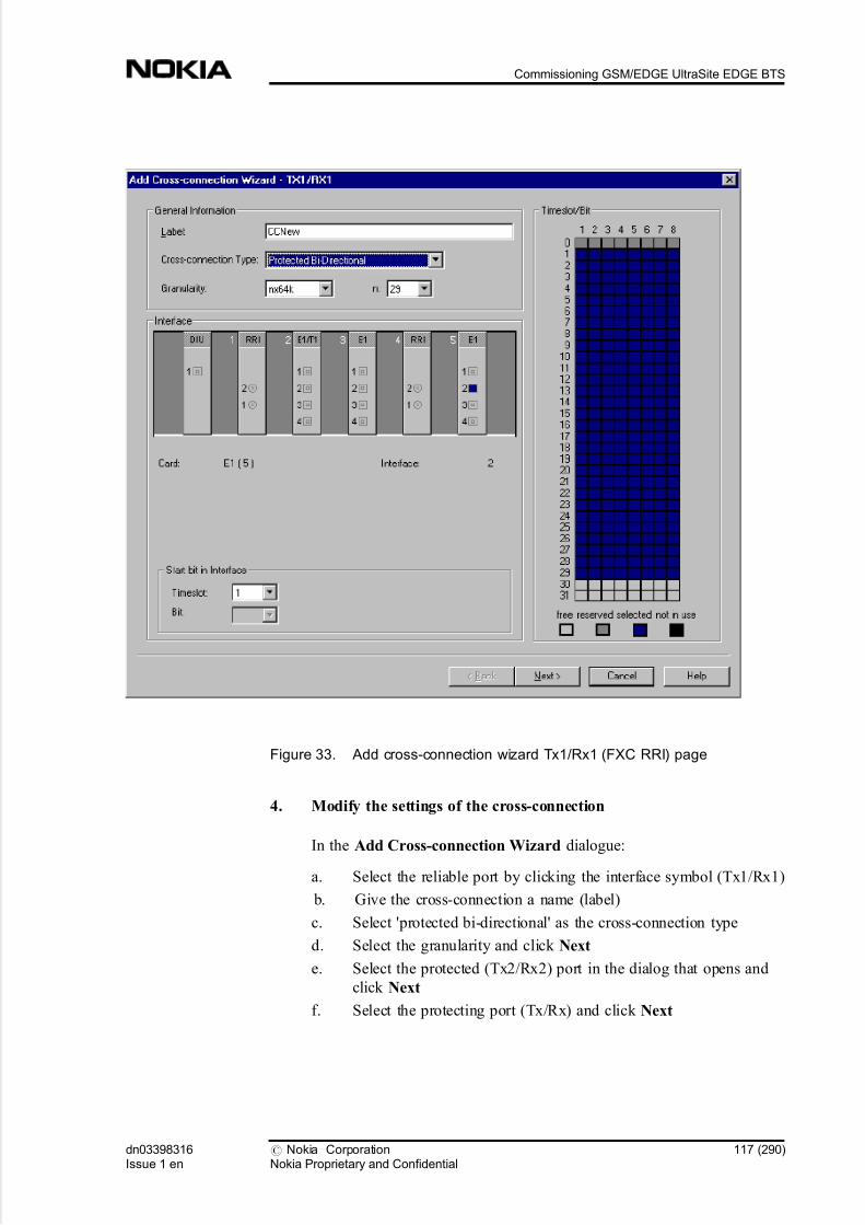
5/14/2018 Commissioning Ultrasite EDGE BTS - slidepdf.com
http://slidepdf.com/reader/full/commissioning-ultrasite-edge-bts 117/290
Figure 33. Add cross-connection wizard Tx1/Rx1 (FXC RRI) page
4. Modify the settings of the cross-connection
In the Add Cross-connection Wizard dialogue:
a. Select the reliable port by clicking the interface symbol (Tx1/Rx1)
b. Give the cross-connection a name (label)
c. Select 'protected bi-directional' as the cross-connection type
d. Select the granularity and click Next
e. Select the protected (Tx2/Rx2) port in the dialog that opens and
click Next
f. Select the protecting port (Tx/Rx) and click Next
dn03398316Issue 1 en
# Nokia CorporationNokia Proprietary and Confidential
117 (290)
Commissioning GSM/EDGE UltraSite EDGE BTS

5/14/2018 Commissioning Ultrasite EDGE BTS - slidepdf.com
http://slidepdf.com/reader/full/commissioning-ultrasite-edge-bts 118/290
Expected outcome
The Condition dialogue opens.
Figure 34. Condition dialogue (enabled only for protected cross-connections)
5. Modify the conditions of the cross-connection
Before you start
Note
Local (valid inside the 2 Mbit/s signal) or Global (valid inside the whole node)
common conditions are not supported in MetroHub or UltraSite BTS Hub
protected cross-connections.
118 (290) # Nokia CorporationNokia Proprietary and Confidential
dn03398316Issue 1 en
Commissioning UltraSite EDGE BTS

5/14/2018 Commissioning Ultrasite EDGE BTS - slidepdf.com
http://slidepdf.com/reader/full/commissioning-ultrasite-edge-bts 119/290
If you need to create several protected connections with common condition
data, you can store the condition data by clicking Set As Default. The data
is saved for the duration of the session and it is always taken into use by
default for new protected connections.
In the Condition dialogue:
a. Select an FXC unit
b. If the unit is an FXC RRI, then select a Flexbus and channel in the
FXC unit
Else select an interface in the FXC unit
c. Select a time slot in the FXC unit
d. Select a bit in the FXC unit
e. Set the polarity and click OK
Expected outcome
The Condition dialogue closes.
The information displayed in the last page of the wizard provides an overview of
the new cross-connection to be created and also seeks certain parameters (if
required) depending on the selected cross-connection type in the first termination
point page of the wizard. The arrows drawn in the space between termination
point buttons indicate the direction of the cross-connection and its type.
The figure illustrates how the information is displayed when the desired Flexbus,channel and platform interface of an FXC RRI unit are selected on the first page
of the Add Cross-connection Wizard.
dn03398316Issue 1 en
# Nokia CorporationNokia Proprietary and Confidential
119 (290)
Commissioning GSM/EDGE UltraSite EDGE BTS

5/14/2018 Commissioning Ultrasite EDGE BTS - slidepdf.com
http://slidepdf.com/reader/full/commissioning-ultrasite-edge-bts 120/290
Figure 35. Add cross-connection wizard's last page: overview
7.2.23 Adding cross-connections in the graphic view
Summary
A fast and easy way to add cross-connections is via the graphic view in the
Cross-connections window. You can select the unit, physical interface and
granularity as shown in the figure below.
120 (290) # Nokia CorporationNokia Proprietary and Confidential
dn03398316Issue 1 en
Commissioning UltraSite EDGE BTS

5/14/2018 Commissioning Ultrasite EDGE BTS - slidepdf.com
http://slidepdf.com/reader/full/commissioning-ultrasite-edge-bts 121/290
Figure 36. Selecting interface and granularity in the graphic view
Steps
1. Press down the left mouse button to select an interface
2. Drag the line to the second termination point and release the mouse
button
Expected outcome
A pop-up menu is displayed.
3. Select the granularity
Expected outcome
The Cross-connection wizard opens.
4. Select the cross-connection type on the first page of the wizard
5. Select the correct channel on the second page of the wizard
6. Click Next
7. If the selected unit is a FXC RRI unit
Then
Select the desired channel
dn03398316Issue 1 en
# Nokia CorporationNokia Proprietary and Confidential
121 (290)
Commissioning GSM/EDGE UltraSite EDGE BTS
5/14/2018 Commissioning Ultrasite EDGE BTS - slidepdf.com
http://slidepdf.com/reader/full/commissioning-ultrasite-edge-bts 122/290
8. Click Finish
7.2.24 Modifying cross-connections
Purpose
You can modify existing cross-connections.
Steps
1. Click Modify in the Cross-connections window
Expected outcome
The Modify Cross-connection Wizard opens. The layout of this wizard isexactly the same as in the Add Cross-connection Wizard.
Further information
Note
In the connection mode, only connections in the inactive bank can be edited.
In order for the modified cross-connections to take effect, you must
activate the bank manually. For instructions, see Managing cross-
connection banks.
2. Modify the settings as desired
Further information
You can also modify cross-connections via a pop-up menu. Right-click the
selected cross-connection in the inactive bank.
7.2.25 Creating and exporting a cross-connection file
Steps
1. Open the manager and start the file mode by selecting File New
2. Install the desired FXC units and radio outdoor units (OU) in the
Equipment window
122 (290) # Nokia CorporationNokia Proprietary and Confidential
dn03398316Issue 1 en
Commissioning UltraSite EDGE BTS

5/14/2018 Commissioning Ultrasite EDGE BTS - slidepdf.com
http://slidepdf.com/reader/full/commissioning-ultrasite-edge-bts 123/290
Further information
Note
In order to restore the settings stored in a previously exported node (or cross-
connection xcs) file, the hardware configuration of the node/xcs file must match
the hardware configuration of the node where it will be restored.
3. Open the Cross-connections window by selecting Configuration
Cross-connections...
4. Create all needed connections into an inactive bank
5. Click the Export button on the Cross-connections window
6. Save the exported file in the desired location
7.2.26 Importing a cross-connection file
Steps
1. Connect to the node or open a file
2. Select Configuration Cross-connections...
Expected outcome
The Cross-connections window opens.
3. Select the inactive bank
4. Click the Import button on the Cross-connections window
5. Select the desired file in the dialogue that opens
6. Click the Open button
Expected outcome
The file is imported to the inactive cross-connection bank.
Note
dn03398316Issue 1 en
# Nokia CorporationNokia Proprietary and Confidential
123 (290)
Commissioning GSM/EDGE UltraSite EDGE BTS
5/14/2018 Commissioning Ultrasite EDGE BTS - slidepdf.com
http://slidepdf.com/reader/full/commissioning-ultrasite-edge-bts 124/290
Cross-connections can only be imported to the inactive bank. For the imported
settings to take effect, the bank has to be activated.
7.2.27 Managing cross-connection banks
Summary
Cross-connection banks can be activated, copied, and cleared.
Steps
1. If you want to activate an inactive bank
Then
Click Activate in the Cross-connection view
2. If you want to copy a bank
Then
Click Copy in the Cross-connection view
Expected outcome
This creates a copy of the cross-connections from an active bank to
inactive bank.
Further information
This is useful if you want to create another cross-connection bank with
only minor differences from the original.
3. If you want to clear a bank
Then
Select all cross-connections in the bank and click Remove in the Cross-
connection view
Expected outcome
This removes all cross-connections from the inactive bank.
124 (290) # Nokia CorporationNokia Proprietary and Confidential
dn03398316Issue 1 en
Commissioning UltraSite EDGE BTS

5/14/2018 Commissioning Ultrasite EDGE BTS - slidepdf.com
http://slidepdf.com/reader/full/commissioning-ultrasite-edge-bts 125/290
7.2.28 Removing cross-connections
Purpose
You can permanently remove a cross-connection from a bank.
Steps
1. Select the connection or connections you wish to delete
2. Click Remove in the Cross-connections window
Expected outcome
Before removing the cross-connections, the manager asks you to confirm if
you want to go ahead with the removal. After you have confirmed theremoval, the manager removes the cross-connection(s) from the bank.
Further information
You can also remove cross-connections via a pop-up menu. Right-click the
selected cross-connection in the inactive bank.
7.3 Administering UltraSite BTS Hub
7.3.1 Starting the node manager
Before you start
Nokia node managers have been installed in your computer. For instructions, see
Installing software from Nokia SiteWizard .
Steps
1. Start Windows
2. Click Start, and then point to Programs Nokia Applications
3. Click the node manager
Expected outcome
When the node manager is started, an application window appears. The
application window gives you access to all the other windows in the manager. No
other windows are initially open.
dn03398316Issue 1 en
# Nokia CorporationNokia Proprietary and Confidential
125 (290)
Commissioning GSM/EDGE UltraSite EDGE BTS
5/14/2018 Commissioning Ultrasite EDGE BTS - slidepdf.com
http://slidepdf.com/reader/full/commissioning-ultrasite-edge-bts 126/290
The node manager application window has a toolbar that provides short-cuts to
frequently needed menu commands. The window also has a status bar, which
displays:
. connection parameters
. help information on the currently selected menu command
. COM-port that is currently connected
. if the application is running in file mode or connected mode
7.3.2 Using UltraSite BTS Hub or MetroHub Manager online help
Purpose
Nokia node managers feature comprehensive context-sensitive online help that
provides help on all aspects of using the manager. Help is available at any time
when you are using the manager.
Steps
1. Give the menu command Help Help Topics
Or
Press the F1 button
Or
Press the Help button of a dialogue
Expected outcome
The manager opens the Help Topics window.
Or
The manager displays the context-sensitive help of the current dialogue.
Further information
The context-sensitive help describes only the purpose and the layout of the
dialogue or window in question. If you want to find more information
about the node manager functions, it can be viewed by selecting the Help
Topics button and then pressing the Contents tab and double-clicking the
topic.
126 (290) # Nokia CorporationNokia Proprietary and Confidential
dn03398316Issue 1 en
Commissioning UltraSite EDGE BTS

5/14/2018 Commissioning Ultrasite EDGE BTS - slidepdf.com
http://slidepdf.com/reader/full/commissioning-ultrasite-edge-bts 127/290
2. Select a topic from the Contents or the Index
Expected outcome
The selected topic is displayed.
Further information
The FXC unit-related online help is available from Help Transmission Unit
Managers. The help covers all the FXC units.
For further information on using online help in Microsoft Windows, refer to the
Microsoft Windows user manuals.
7.3.3 Overview of connecting to the node online
Purpose
Nokia MetroHub or UltraSite BTS Hub Manager offers two ways to work: online
and offline. In the online mode you can manage an actual node and all changes
are made directly to the node. The offline mode allows you to manage a virtual
node.
Note
You cannot fully manage the node in the offline mode. For example, not all
settings can be modified.
Before you start
Start Hub or MetroHub Manager. Select the node that you want to manage by
establishing a connection to the FXC unit acting as the node control unit . This
may be done in three alternative ways:
Steps
1. Connect locally via LMP
Connect via Q1 address
Or
Connect using sobriquet connection
dn03398316Issue 1 en
# Nokia CorporationNokia Proprietary and Confidential
127 (290)
Commissioning GSM/EDGE UltraSite EDGE BTS
5/14/2018 Commissioning Ultrasite EDGE BTS - slidepdf.com
http://slidepdf.com/reader/full/commissioning-ultrasite-edge-bts 128/290
For information on how to access the node when you give the sobriquet on
the command line, see General Communication Service User s Manual that
is available in NOLS.
Further information
Accessing the node remotely via NMS
Security in Hub or MetroHub Manager is governed by the operating environment
of the manager.
. Windows NT4.0 / Windows 2000
When using an NMS system for remote management, the user must have
the proper rights. To access a node manager, a user has to have the
appropriate privileges in NetAct and Node Manager Server.
. Windows 95 and 98
Hub and MetroHub Manager do not support NMS use in Windows 95 and
98.
7.3.4 Connecting locally via LMP
Before you start
Ensure that the LMP cable is connected.
Steps
1. Select Connection Connect Locally
Note
This menu command can only be used if the local management port is used.
Expected outcome
The manager connects to the node control unit (any FXC unit in slot 1)
using the fixed LMP address 4080 (default port settings: COM1, speed:
9600; these settings can be changed in the Local Connection folder which
is opened by selecting Tools Options...).
128 (290) # Nokia CorporationNokia Proprietary and Confidential
dn03398316Issue 1 en
Commissioning UltraSite EDGE BTS

5/14/2018 Commissioning Ultrasite EDGE BTS - slidepdf.com
http://slidepdf.com/reader/full/commissioning-ultrasite-edge-bts 129/290
When the connection to the node has been established, the Equipment
window opens automatically.
Figure 37. MetroHub or UltraSite BTS Hub Manager Equipment window
(Connected to node)
The window presents a schematic overview of the node. You can select a
unit by clicking it. When an FXC unit or an outdoor unit is selected, a unit-
specific menu appears on the menu bar, on the left side of the MetroHub or
UltraSite BTS Hub Manager Tools menu. Outdoor units are managed
through FXC RRI units.
Note
Closing the Equipment window causes the connection to the node or file to be
lost.
dn03398316Issue 1 en
# Nokia CorporationNokia Proprietary and Confidential
129 (290)
Commissioning GSM/EDGE UltraSite EDGE BTS

5/14/2018 Commissioning Ultrasite EDGE BTS - slidepdf.com
http://slidepdf.com/reader/full/commissioning-ultrasite-edge-bts 130/290
The status of the units is indicated by means of colour coding.
Table 18. Colour codes indicating the status of units
Colour code Status of unit
Dark grey Empty slot
Diagonal stripes Physically inserted, logically uninstalled
Light grey Physically inserted, logically installed
(=operational unit)
Dark grey with a light grey border; type of
unit indicated
Physically removed, logically installed
(=missing unit)
Light grey with a red border; type of unit
indicated
Physically inserted, wrong unit logically
installed (=mismatched unit)
Light grey with a blue border; type of unit
indicated
Software version mismatch. The unit's
software is not compatible with the master
unit's software.
Non-FXC units have to be installed in order to be operational. By default,
the following units are in use: power supply unit (on the left), power
interface panel, fan unit, and interface unit.
Further information
If several nodes are chained via LMPs, the connection must be established as
described in Connecting via Q1 address.
For information on installing and uninstalling the units logically with the
manager, see Installing units logically with the manager and Uninstalling units
logically with the manager .
7.3.5 Connecting via Q1 address
Purpose
The MetroHub or UltraSite BTS Hub node can also be accessed via the Nokia
Connection Tool.
Steps
1. Select Connection Connection Tool...
130 (290) # Nokia CorporationNokia Proprietary and Confidential
dn03398316Issue 1 en
Commissioning UltraSite EDGE BTS

5/14/2018 Commissioning Ultrasite EDGE BTS - slidepdf.com
http://slidepdf.com/reader/full/commissioning-ultrasite-edge-bts 131/290
Expected outcome
The Connect to Node dialogue opens.
Figure 38. Nokia Connection Tool (Connect to Node dialogue)
2. Define the needed parameters
Select a previously configured connection
Further information
Detailed information on using the Nokia Connection Tool is available in
General Communication Service User s Manual .
3. Fill in the LMP or Q1 address of the equipment to the Q1 Address
field, depending on the connection used
Further information
If the LMP is chained, a unique Q1 address must be selected for the LMP,
and the connection to the node is established with the Connection Tool...
option in the manager.
dn03398316Issue 1 en
# Nokia CorporationNokia Proprietary and Confidential
131 (290)
Commissioning GSM/EDGE UltraSite EDGE BTS

5/14/2018 Commissioning Ultrasite EDGE BTS - slidepdf.com
http://slidepdf.com/reader/full/commissioning-ultrasite-edge-bts 132/290
7.3.6 Connecting to the node offline
Purpose
The offline mode allows you to manage a virtual node. All the information is
saved in a file in your computer and this file represents an image of a real node.
By using this feature, it is possible to create a template which may be used to
commission numerous installations with similar configurations. You can also use
this to make changes to an installation while at the office before going on-site.
Summary
You can connect to the node offline either by creating a new virtual node offline
file or by opening an existing file. For instructions on how to create a new node
file, see the MetroHub or UltraSite EDGE BTS documentation set.
Steps
1. To open an existing file
Steps
a. Select File Open...
b. Select the file to be opened
Further information
When in the offline mode, MetroHub or UltraSite BTS Hub Manager does not
verify the entered configuration. The configuration is verified with the actual
equipment when it is sent to the node. If the created configuration does not
correspond to the actual installed equipment, a warning is displayed.
132 (290) # Nokia CorporationNokia Proprietary and Confidential
dn03398316Issue 1 en
Commissioning UltraSite EDGE BTS

5/14/2018 Commissioning Ultrasite EDGE BTS - slidepdf.com
http://slidepdf.com/reader/full/commissioning-ultrasite-edge-bts 133/290
Figure 39. MetroHub or UltraSite BTS Hub Manager Equipment window (offline
mode)
7.3.7 Resetting transmission units
Purpose
Resetting a node is an exceptional situation in normal operation, but when the
network is initially built, a situation may occur when resetting the node is
necessary. Generally, there are two kinds of resets: one for the whole node and the
other for a single transmission unit. Resets to the transmission units can be given
using the node manager.
dn03398316Issue 1 en
# Nokia CorporationNokia Proprietary and Confidential
133 (290)
Commissioning GSM/EDGE UltraSite EDGE BTS

5/14/2018 Commissioning Ultrasite EDGE BTS - slidepdf.com
http://slidepdf.com/reader/full/commissioning-ultrasite-edge-bts 134/290
In the Resets dialogue you can select the type of reset and the targeted units. The
reset dialogue is only accessible in the connected mode and factory settings are
only allowed in LMP connections. Hardware resets are possible for all units.
The node settings are not unit-specific settings maintained by the master unit like
the cross-connection settings. Factory reset restores the default factory settings.
The factory reset is automated when you start the Commissioning Wizard or
restore backup settings.
Steps
1. Select Maintenance Resets...
Expected outcome
The Resets dialogue opens.
Figure 40. Resets dialogue
134 (290) # Nokia CorporationNokia Proprietary and Confidential
dn03398316Issue 1 en
Commissioning UltraSite EDGE BTS

5/14/2018 Commissioning Ultrasite EDGE BTS - slidepdf.com
http://slidepdf.com/reader/full/commissioning-ultrasite-edge-bts 135/290
Further information
In this dialogue you can select which part of the UltraSite BTS Hub or
MetroHub to reset. Selecting a unit resets the corresponding unit, and
selecting the node resets the master unit of the node. When the command is
sent to the node, UltraSite BTS Hub or MetroHub carries out the desired
resets.
There are two different kinds of node resets:
. Hardware reset
This reset equals hardware reset to a power off/on of transmission
units. The traffic is cut and all settings remain unaffected. In case of
a hardware reset to the node, the selection is disabled because the
reset is the same as the one to the Unit1 (Node control unit).
. Restore factory settings
This reset restores the node to its original settings. For a node
selection, all node settings (cross-connections, synchronisation,
EOC etc.) are deleted. If a unit is selected, the unit settings are
deleted. After the settings have been deleted, the corresponding unit
is reset, and the default settings are taken into use.
2. Select the units to be reset
3. Click Send
Expected outcome
If you select all units, the resets are executed in the following order:
1. Reset of the outdoor units.
2. Reset of the FXC units.
3. Waiting for the master unit to recover.
4. Reset of the node.
5. Waiting for the node to recover.
6. The initial value for LMP speed is restored.
7.3.8 Saving node information in a file
Purpose
Node information can be saved in a file for later use both online and offline.
dn03398316Issue 1 en
# Nokia CorporationNokia Proprietary and Confidential
135 (290)
Commissioning GSM/EDGE UltraSite EDGE BTS

5/14/2018 Commissioning Ultrasite EDGE BTS - slidepdf.com
http://slidepdf.com/reader/full/commissioning-ultrasite-edge-bts 136/290
If you save the node information online after commissioning the node, you can
use the saved file as the backup file. This type of file cannot be used for
commissioning purposes.
The file saved offline can be used in commissioning the node.
Before you start
The Equipment view is open.
Steps
1. Select File Save... or Save As...
Expected outcome
The manager opens the Save Node Settings dialogue.
Figure 41. Save Node Settings dialogue
2. Select either Select all or select the individual units that you want the
settings to be saved for
Further information
136 (290) # Nokia CorporationNokia Proprietary and Confidential
dn03398316Issue 1 en
Commissioning UltraSite EDGE BTS

5/14/2018 Commissioning Ultrasite EDGE BTS - slidepdf.com
http://slidepdf.com/reader/full/commissioning-ultrasite-edge-bts 137/290
Note
Node settings are always saved.
When a particular RRI is selected, all OUs connected to it are automatically
selected (and cannot be unselected). Thus, the settings of the OUs are
automatically saved along with those of the corresponding RRI.
3. Click OK
Expected outcome
The manager opens the Save As dialogue.
4. Give the file a name and select a file type
5. If you want to edit the file header
Then
Click the Edit button
6. If you edited the file header
Then
Click OK
Expected outcome
The manager returns to the Save As dialogue.
7. Click Save
Expected outcome
The file is saved.
Further information
UltraSite BTS Hub or MetroHub supports two site configuration file formats, .
nod (for node offline file) and .xml. It is also possible to read older node files with
the extension .dat.
dn03398316Issue 1 en
# Nokia CorporationNokia Proprietary and Confidential
137 (290)
Commissioning GSM/EDGE UltraSite EDGE BTS

5/14/2018 Commissioning Ultrasite EDGE BTS - slidepdf.com
http://slidepdf.com/reader/full/commissioning-ultrasite-edge-bts 138/290
7.3.9 Restoring backup settings from a file
Purpose
It is possible to save node and unit settings into a backup file (both extensions .
xml and .nod), see Saving node information in a file. The backup file can be used
in restoring backup settings of the node or the units.
Before you start
To be able to restore backup settings, the user must have a backup file. It is
recommended to make a backup file (in .nod format) after a node has been
commissioned and it has been verified that it functions as planned.
Note
Previously the backup file has been saved in .dat format. A file in .dat format can
still be used, but all new backup files as well as old .dat files that have been
modified are saved in the .nod format.
The backup dialogue is only accessible in the connected mode.
Note
Before restoring the settings at the node level, the node must be in the factory
defaults state. If it is not, the factory settings are restored automatically.
Steps
1. Select Maintenance Restore Backup Settings
Expected outcome
The Restore Backup Settings dialogue opens.
138 (290) # Nokia CorporationNokia Proprietary and Confidential
dn03398316Issue 1 en
Commissioning UltraSite EDGE BTS

5/14/2018 Commissioning Ultrasite EDGE BTS - slidepdf.com
http://slidepdf.com/reader/full/commissioning-ultrasite-edge-bts 139/290
Figure 42. Restore Backup Settings dialogue
2. Click Browse...
Expected outcome
The manager opens the standard Windows open file dialogue.
3. Browse to the file, select it and click Open
Expected outcome
The file is opened in the backup dialogue, and the manager type and unit
configuration is checked.
dn03398316Issue 1 en
# Nokia CorporationNokia Proprietary and Confidential
139 (290)
Commissioning GSM/EDGE UltraSite EDGE BTS

5/14/2018 Commissioning Ultrasite EDGE BTS - slidepdf.com
http://slidepdf.com/reader/full/commissioning-ultrasite-edge-bts 140/290
Figure 43. Restore Backup Settings dialogue
If the file contains correct data for the unit, the settings can be sent to the
selected units.
If the file contains data that does not match to the configuration of the
node, the manager gives a note and the user has to select a file containing
the right configuration.
4. Select the units where you want to send the file to
5. Click Send
Expected outcome
The manager sends the settings to the selected units. During sending, the manager
displays a progress dialogue. When the settings have been sent, the dialogue is
closed.
140 (290) # Nokia CorporationNokia Proprietary and Confidential
dn03398316Issue 1 en
Commissioning UltraSite EDGE BTS

5/14/2018 Commissioning Ultrasite EDGE BTS - slidepdf.com
http://slidepdf.com/reader/full/commissioning-ultrasite-edge-bts 141/290
7.3.10 Creating a configuration report
Summary
The configuration report contains all the configuration information of the
connected Nokia MetroHub or UltraSite BTS Hub.
Steps
1. Select Tools Reports Configuration Report
Expected outcome
The Configuration Report window opens.
Figure 44. Configuration report
The configuration report contains all the configuration information of the
connected Nokia MetroHub or UltraSite BTS Hub. You can also modify
the contents of the configuration report.
2. Modify the contents of the configuration report
Steps
dn03398316Issue 1 en
# Nokia CorporationNokia Proprietary and Confidential
141 (290)
Commissioning GSM/EDGE UltraSite EDGE BTS

5/14/2018 Commissioning Ultrasite EDGE BTS - slidepdf.com
http://slidepdf.com/reader/full/commissioning-ultrasite-edge-bts 142/290
a. Click the Options button
Expected outcome
The Configuration Report Options dialogue opens.
Figure 45. Configuration Report Options dialogue
b. Select what to include in the report
Further information
The following options exist:
. Power, Fan. When selected, the information on the power and
fan units are included in the report.
. Detailed Unit Identification. When selected, the hardware/ software configuration part of the report contains information
on the hardware and software versions.
. Synchronisation. When selected, information about node
synchronisation is included.
. Q1 Management and Service IF. When selected, the report
includes information on Q1 management and service interface
of the node.
142 (290) # Nokia CorporationNokia Proprietary and Confidential
dn03398316Issue 1 en
Commissioning UltraSite EDGE BTS

5/14/2018 Commissioning Ultrasite EDGE BTS - slidepdf.com
http://slidepdf.com/reader/full/commissioning-ultrasite-edge-bts 143/290
. Cross-connections. When selected, the report includes
information on cross-connections.
. D-bus allocation. When selected, the report includes
information on D-bus allocation. (Valid only in Nokia UltraSite BTS Hub Manager.)
. EAC and Alarm Config. When selected, the report includes
information on EACs and alarm configuration.
. Include Alarms in Report. When selected, the report includes
information on active alarms.
. Line IF (LIF) and Platform IF (PIF). When selected, the report
includes information on LIF and PIF.
. Radio Settings. When selected, the report includes
information on outdoor units (radios) of the FXC RRI units.
Note
These selections are not saved when you close the Configuration Report
dialogue.
c. Click OK
Expected outcome
The configuration report is saved as a text file with the extension .cnr and has to
be opened with a text editor.
7.3.11 Printing information
Summary
You can print information from Equipment, Cross-connections and Alarm
windows.
Steps
1. Open the window which you want to print information from
2. Select File Print
dn03398316Issue 1 en
# Nokia CorporationNokia Proprietary and Confidential
143 (290)
Commissioning GSM/EDGE UltraSite EDGE BTS

5/14/2018 Commissioning Ultrasite EDGE BTS - slidepdf.com
http://slidepdf.com/reader/full/commissioning-ultrasite-edge-bts 144/290
7.4 Configuring GSM/EDGE UltraSite EDGE BTS for manual commissioning
7.4.1 Creating a new HW configuration to commission GSM/EDGEUltraSite EDGE BTS
Before you start
Review the Overview of commissioning GSM/EDGE UltraSite EDGE BTS . Pay
careful attention to all warnings and cautions.
Summary
HW configuration is defined with BTS HW Configurator.
The quickest way to create a new BTS HW configuration is to run the Wizard
(Configuration | Wizard ). The Wizard takes you through the task sequence in the
correct order and provides instructions for each task. Additional information is
available through the Help button.
If there is no predefined HW configuration file available for the BTS, you can
create the configuration with the Create New Configuration option in the Wizard.
Creating a new configuration with the Wizard requires no BTS connection, so
you can create the configuration in advance and save it as an .hwc file.
The Passive Units view in BTS HWConfigurator allows you to enter information
concerning all units that are not autodetected. This information includes part and
serial numbers. This information is not required during commissioning and is not
needed to get the BTS operational. It is possible to enter and update this
information any time before, during, and after commissioning.
You can enter passive unit information with BTS HW Configurator off-line and
on-line. You can also use a barcode reader to scan the part and serial numbers off
stickers on the units. The SW recognizes the part number and identifies the unit
type. One problem is that using a barcode reader with the PC requires the use of
one serial port and many laptop computers have only one serial port. In this case,
you must use BTS HW Configurator off-line to scan in the part and serialnumbers. Once this is completed and the information is saved to a file, the
hardware information file (.hwi) can be downloaded to the BTS.
144 (290) # Nokia CorporationNokia Proprietary and Confidential
dn03398316Issue 1 en
Commissioning UltraSite EDGE BTS

5/14/2018 Commissioning Ultrasite EDGE BTS - slidepdf.com
http://slidepdf.com/reader/full/commissioning-ultrasite-edge-bts 145/290
Note
If you change the HW configuration in any way after the BTS commissioning has
been finished, you will have to perform a BCF reset in order to make the changesactive.
Steps
1. Open BTS HW Configurator.
Select Nokia BTS HW Configurator from the Nokia Applications submenu
in the Start | Programs menu in Windows.
2. Start the HW Configurator Wizard.
Select the Wizard command on the Configuration menu.
3. Set up new configuration.
a. Select the Create New Configuration option from the Configuration
Wizard window and click the Next button.
b. Select <New> from Sector Configuration window list and common
network type from the drop down list.
c. If you want to change the network type of individual TSx units,
click the Modify button.
Alternatively, you can select one of the predefined configurations from the
Modify Sector and Network list, to be modified further.
4. Define TSx configuration on the Define TSx configuration window.
a. Select the TSx unit from the Define TSx configuration window list.
b. Select the basic configuration for the selected TSx unit from the
Configuration Type drop-down list.
Note
There are four configuration types to select from:
. Bypass with DDU stands for one TSx unit connecting to a
DDU half.
. 2-way DDU stands for two TSx units connecting to a DDU
half.
dn03398316Issue 1 en
# Nokia CorporationNokia Proprietary and Confidential
145 (290)
Commissioning GSM/EDGE UltraSite EDGE BTS

5/14/2018 Commissioning Ultrasite EDGE BTS - slidepdf.com
http://slidepdf.com/reader/full/commissioning-ultrasite-edge-bts 146/290
. 4-way DDU stands for four TSx units connecting to a DDU
half.
. RTC stands for six TSx units RTC.
c. Click the Set button for each TSx unit selected.
d. Click the Next button.
5. Define RX diversity for each TSx unit on the Define RX Diversity
Cabling window.
a. Select the TSx unit from the Define RX Diversity Cabling window
list.
b. Select the combiner unit for the selected TSx unit from the drop-
down list.c. Click the Set button to update the defined cabling configuration.
d. Click the Next button.
6. Define antenna settings on the Define Antenna Settings window.
a. If all antennas use High gain MHAs and/or VSWR monitoring,
select the corresponding options in the Properties for All Connected
Antennas group box of the Define Antenna Settings window.
Note
All UltraSite-specific MHA (MNxx) units are High Gain type. All other MHA
units are Low Gain type.
b. Select an antenna in the Antennas list.
c. Select a unit for the selected antenna from the DVx/RTx list.
d. Update the defined antenna information to the configuration by
clicking Set button.
e. Click the Next button.
7. Verify report on Report of New Configurationwindow and exit
Wizard.
Verify the new configuration report and click the Finish button to exit the
Wizard.
You can modify the configuration manually via properties pages, after the
Wizard is closed.
146 (290) # Nokia CorporationNokia Proprietary and Confidential
dn03398316Issue 1 en
Commissioning UltraSite EDGE BTS

5/14/2018 Commissioning Ultrasite EDGE BTS - slidepdf.com
http://slidepdf.com/reader/full/commissioning-ultrasite-edge-bts 147/290
8. Save new configuration.
Save the new configuration to hard drive by selecting the Save option from
the File menu.
Note
Before saving the new configuration to a file, you can manually make changes to
the unit properties, if necessary.
Alternatively, send the configuration information to the BTS from the BTS
menu using the Send BTS Configuration command.
9. Proceed with Manual Hub configuration of UltraSite EDGE BTS.
7.4.2 Using an existing HW configuration to commission GSM/EDGEUltraSite EDGE BTS
Before you start
Review the Overview of commissioning GSM/EDGE UltraSite EDGE BTS . Pay
careful attention to all Warnings and Cautions.
This procedure requires a predefined HW configuration file (with file name
extension .hwc) created from Creating a new HW configuration to commission
UltraSite EDGE BTS .
Note
Creating a new configuration with the Wizard requires no BTS connection, so
you can create the configuration in advance and save it as an .hwc file. A BTS
HW configuration file (Basic Configs.hwc) with basic UltraSite BTS
configurations is delivered with Nokia BTS HW Configurator. You can use the
configurations as such, if possible, or you can modify them to suit your purposes.
Summary
HW configuration information is defined with BTS HW Configurator.
Steps
dn03398316Issue 1 en
# Nokia CorporationNokia Proprietary and Confidential
147 (290)
Commissioning GSM/EDGE UltraSite EDGE BTS

5/14/2018 Commissioning Ultrasite EDGE BTS - slidepdf.com
http://slidepdf.com/reader/full/commissioning-ultrasite-edge-bts 148/290
1. Open the BTS HW Configurator.
Select Nokia BTS HW Configurator from the Nokia Applications submenu
in the Start | Programs menu in Windows.
2. Start the HW Configurator Wizard.
Select the Wizard command on the Configuration menu.
3. Retrieve the desired HW configuration.
a. Select the Check BTS Configuration and Update BTS option from
the Wizard Welcome window.
The Wizard automatically displays the BTS HW configuration file
that was used last. b. Select the BTS to be configured on the Select Configuration
window.
c. Click the Next button.
4. If the configuration you want is not in the list,
Then
Locate the appropriate configuration file.
a. Click the Browse button to load the appropriate .hwc file.
b. Click theNext button.c. If BTS connection is not enabled, BTS HW Configurator asks if you
want to activate it.
Note
BTS connection requires that the LMP cable is connected from the PC to the
BTS. For information about the LMP cable, see Connecting LMP cable for
commissioning UltraSite EDGE BTS .
5. Ensure that the configuration information is correct on the BTS
connection window.
The BTS Connection Status list displays information about the BTS
connection and the state of the BCF.
Click the Next button when the BCF is in the correct state.
148 (290) # Nokia CorporationNokia Proprietary and Confidential
dn03398316Issue 1 en
Commissioning UltraSite EDGE BTS

5/14/2018 Commissioning Ultrasite EDGE BTS - slidepdf.com
http://slidepdf.com/reader/full/commissioning-ultrasite-edge-bts 149/290
6. Verify other associated information on the Cabinet Information
window.
You can view information concerning the BTS cabinet type, clock synchronisation and the Line Terminal Equipment (LTEs) in the Site
Support cabinet.
When done, click the Next button.
7. Verify cross-connections on the BB2-TSx Cross-connections window.
Verify the BB2 cross-connection to the TSxx units.
When done, click the Next button.
Note
If there are units that have not been detected automatically, click the Autodetect
button. The BCF must be in the BCF Commissioning state. You can select the
View Autodetected Units option to see the autodetected units in the Graphical
view in BTS HW Configurator.
Note
. BSS 9 - All BSS 9 features can be used with the CX3.0/3.3 SW
releases and the current SW release PU1.0-3 with the cross-
connection functionality in case existing equipment has not been
configured to use default connections. However, Nokia recommends
that sites are reconfigured so that the cross-connection functionality
is not used, especially if technical problems occur.
. BSS 10/10.5 - The cross-connection functionality is not supported in
CX3.0/3.3 SW releases when the new BSS10/10.5 features are used.
In order to use these features, you must reconfigure the sites to use
default connections.
. BSS 11 - The cross-connection functionality will be permanently
removed in the CX4.0 SW release.
dn03398316Issue 1 en
# Nokia CorporationNokia Proprietary and Confidential
149 (290)
Commissioning GSM/EDGE UltraSite EDGE BTS

5/14/2018 Commissioning Ultrasite EDGE BTS - slidepdf.com
http://slidepdf.com/reader/full/commissioning-ultrasite-edge-bts 150/290
Note
If a TSx unit does not exist in the configuration, the unit will be in brackets and
greyed out.
8. Verify the TX, RX main and RX diversity cable connections for TRX1
to TRX12 on the Current Cabling window.
Clicking a cabling option in the list displays the selected cabling in the
Graphical view on the left. The View Settings group box specifies the
appearance of the Graphical view enabling you to show/hide wideband and
multicoupler units and non-active cabling.
When done, click the Next button.
9. Verify antenna unit connections shown on the Antenna Settings
window.
To enable VSWR monitoring for an antenna,
a. Select the antenna from the list.
b. Select theVSWR Monitoring Enabled option.
c. Click on an antenna in the list to display the corresponding antenna
cable in the Graphical view.d. If the MHA type is High gain, change attenuation values, if desired.
Note
All UltraSite-specific MHA (MNxx) units are High Gain type. All other MHA
units are Low Gain type.
e. Click the Next button.
10. Open a HW information file from the Passive Units window.
a. Click on the desired folder to expand it and then click on the desired
hardware unit.
b. Click theImport button to open the corresponding HW information
file (.hwi).
c. When done, click the Next button.
150 (290) # Nokia CorporationNokia Proprietary and Confidential
dn03398316Issue 1 en
Commissioning UltraSite EDGE BTS

5/14/2018 Commissioning Ultrasite EDGE BTS - slidepdf.com
http://slidepdf.com/reader/full/commissioning-ultrasite-edge-bts 151/290
Note
Passive unit information is not needed to make the BTS operational.
11. If you want to save the configuration report to a file,
Then
Select location and filename in the BTS Configuration Report window.
Enter the path and filename in the Save As field or click the Browse button
to specify the location and filename.
12. Save configuration information and exit the Wizard.
Click the Finish button to save the configuration information in the BTS
and exit the Wizard.
13. Exit BTS HW Configurator.
14. Proceed with Manual Hub configuration of UltraSite EDGE BTS.
7.5 Commissioning GSM/EDGE UltraSite EDGE BTSwith XML Configuration File
7.5.1 Commissioning UltraSite EDGE BTS based on an off-line node file
Summary
To commission the BTS transmission with a node file, send the file to the node
during the commissioning procedure with the Nokia UltraSite BTS Hub
Commissioning Wizard. This allows more network setup to be done off-site. The
site configuration file (.xml extension) is usually provided by network transmission planning.
Nokia NetAct Transmission Planning Tools do not support all the required
parameters of the UltraSite BTS needed to fully commission the BTS. Missing
settings are added to the file using UltraSite BTS Hub Manager.
The Unsupported XML parameters table lists the XML parameters that are not
supported by the Nokia NetAct Planning Tools. Obligatory parameters that must
be added are marked with an asterisk.
dn03398316Issue 1 en
# Nokia CorporationNokia Proprietary and Confidential
151 (290)
Commissioning GSM/EDGE UltraSite EDGE BTS

5/14/2018 Commissioning Ultrasite EDGE BTS - slidepdf.com
http://slidepdf.com/reader/full/commissioning-ultrasite-edge-bts 152/290
Table 19. Unsupported XML parameters
Category Parameters
TruNet TruNet Status
IP Address
Site Data
D-bus Allocation Signalling Type
EDAP Allocation
Identifications Equipment Name
Group Name
Site Allocation
Node and Unit installation information
Cross-connections Cross-connection label
Q1 Management Q1 group address
Q1 baud rate
Hybrid switches* ( processor , internal,
internal to external and external
EOC settings*
Synchronisation Synchronisation sources*
Unit Unit name and installation information
Interface mode* (FXC E1/T1)
Interface name (FXC E1 and FXC E1/T1)
Interface CRC usage*
Operation mode* (FXC RRI)
Radio Hop Information Hop name
Hop frequency*Hop maximum TX power*
Hop temporary ID*
Hop mode*
Hop accept channels*
Note
152 (290) # Nokia CorporationNokia Proprietary and Confidential
dn03398316Issue 1 en
Commissioning UltraSite EDGE BTS
5/14/2018 Commissioning Ultrasite EDGE BTS - slidepdf.com
http://slidepdf.com/reader/full/commissioning-ultrasite-edge-bts 153/290
One XML file can contain commissioning configurations for many BTS sites.
You can only configure one site at a time with UltraSite BTS Hub Manager.
You can add other elements, such as cross-connections, with UltraSite BTS Hub
Manager, but this procedure assumes that all other necessary elements for the site
are already properly planned with Nokia NetAct Planner.
Steps
1. Add unsupported parameters into existing XML file, if available.
2. If a valid XML configuration file cannot be obtained from transmission
network planning,
Then
Create a node off-line file for UltraSite EDGE BTS.
3. Set obligatory radio settings for FlexiHopper.
4. Set obligatory radio settings for MetroHopper.
5. Commission the UltraSite BTS Hub node with the commissioning
wizard.
7.5.2 Editing an XML file for UltraSite EDGE BTS
Before you start
Review Commissioning UltraSite EDGE BTS based on an off-line node file.
Summary
Note
The detailed instructions of manual commissioning apply for all settings in this
section, except for radio settings. For detailed instructions for creation of radio
settings for a node file, see Setting obligatory settings for FlexiHopper and
Setting obligatory settings for MetroHopper .
Steps
dn03398316Issue 1 en
# Nokia CorporationNokia Proprietary and Confidential
153 (290)
Commissioning GSM/EDGE UltraSite EDGE BTS

5/14/2018 Commissioning Ultrasite EDGE BTS - slidepdf.com
http://slidepdf.com/reader/full/commissioning-ultrasite-edge-bts 154/290
1. Start UltraSite BTS Hub Manager and open XML file.
To open the XML file, select menu File | Open....
2. If the XML file contains many sites,
Then
from the Site Selection window, select the site to be modified.
The Equipment view in Nokia UltraSite BTS Hub Manager displays.
3. Add or modify the desired parameters to node file.
See Unsupported XML parameters table for a list of parameters.
4. Save the modified XML Site configuration file.
Select menu File | Save or File | Save As....
5. If you want to modify more than one site,
Then
You must save the file after each site modification.
6. Repeat this procedure from Step 1 until you modify all of the required
sites.
7.5.3 Creating a node off-line file for UltraSite EDGE BTS
Before you start
Review Commissioning UltraSite EDGE BTS based on an off-line node file .
Summary
If you cannot obtain a valid site configuration file from transmission network
planning, you can create the node off-line file (with .dat extension) and include all
of the necessary settings in the file, as provided by transmission network
planning.
154 (290) # Nokia CorporationNokia Proprietary and Confidential
dn03398316Issue 1 en
Commissioning UltraSite EDGE BTS

5/14/2018 Commissioning Ultrasite EDGE BTS - slidepdf.com
http://slidepdf.com/reader/full/commissioning-ultrasite-edge-bts 155/290
Note
The detailed instructions of manual commissioning apply for all settings in this
section, other than radio settings. For detailed instructions on how to create radiosettings for a node file, see Setting obligatory settings for FlexiHopper and
Setting obligatory settings for MetroHopper .
Steps
1. Open BTS Hub Manager.
Select Nokia UltraSite BTS Hub Manager on the Start | Programs | Nokia
Applications menu in Microsoft Windows.
2. Create a new file.
Select File | New in UltraSite BTS Hub Manager.
3. Install the desired FXC units and radios in Equipment view.
4. Perform the necessary settings to the units and the node.
See Manual Hub configuration of GSM/EDGE UltraSite EDGE BTS
(except for the radio settings).
5. Save the node off-line file.
Select File | Save as....
7.5.4 Setting obligatory settings for FlexiHopper
Before you start
Note
Familiarise yourself with the Nokia FlexiHopper by reading FXC RRI User
Manual's Commissioning and Maintenance document before setting Nokia
FlexiHopper radio settings. Refer to the commissioning instructions in Nokia
FlexiHopper Plus Product Documentation before setting FlexiHopper Plus radio
settings.
dn03398316Issue 1 en
# Nokia CorporationNokia Proprietary and Confidential
155 (290)
Commissioning GSM/EDGE UltraSite EDGE BTS

5/14/2018 Commissioning Ultrasite EDGE BTS - slidepdf.com
http://slidepdf.com/reader/full/commissioning-ultrasite-edge-bts 156/290
Summary
To set the obligatory settings for Nokia FlexiHopper and Nokia FlexiHopper
Plus:
Steps
1. Click the FXC RRI unit corresponding to the Nokia FlexiHopper or
FlexiHopper Plus radio.
2. Select Settings -->Operation Mode on the FXC RRI menu. The
Operation Mode dialogue opens.
Figure 46. Operation Mode dialogue
The operation mode of an FXC RRI unit can be Single (no HSB
protection) or 1 IU + 2 OU HSB Protected. The Operation Mode dialogue
also allows the user to select which of the units should be the primary OU,
which is the active protected OU when both OUs are operational.
3. Select the operation mode, and in case of 1 IU + 2 OU HSB, also the
Primary OU TX, and click OK.
156 (290) # Nokia CorporationNokia Proprietary and Confidential
dn03398316Issue 1 en
Commissioning UltraSite EDGE BTS

5/14/2018 Commissioning Ultrasite EDGE BTS - slidepdf.com
http://slidepdf.com/reader/full/commissioning-ultrasite-edge-bts 157/290
When the operation mode of an FXC RRI unit is set to 1 IU + 2 OU HSB
Protected, the protected radio hop is displayed in the Equipment view of
the hub managers.
Figure 47. Protected radio hop in the Equipment view (Note: The Equipment
view of UltraSite BTS Hub is similar to that of MetroHub)
The far end outdoor units and indoor unit are shown for each protected hop
together with information on the hop status. The status information
includes:
. an arrow representing the receive status of each OU,
a. Green arrow = receiving OK
b. Red cross over the arrow = not receiving
. numbers displaying the receive level of each OU in dBm, and
. text TX and/or RX beside each OU representing the currently active
transmitter and receiver.
4. Select Settings --> Outdoor Unit on the FXC RRI menu corresponding
to the FlexiHopper or FlexiHopper Plus radio. The Settings dialogue
opens. The same dialogue is used for Nokia FlexiHopper and
FlexiHopper Plus, but the options vary.
dn03398316Issue 1 en
# Nokia CorporationNokia Proprietary and Confidential
157 (290)
Commissioning GSM/EDGE UltraSite EDGE BTS

5/14/2018 Commissioning Ultrasite EDGE BTS - slidepdf.com
http://slidepdf.com/reader/full/commissioning-ultrasite-edge-bts 158/290
Figure 48. Nokia FlexiHopper or FlexiHopper Plus settings, single
In HSB mode, the Flexbus capacity and OU settings are common for bothradios, except for the Maximum Tx Power and ALCQ (adaptive level
control with quality measure) set point settings.
158 (290) # Nokia CorporationNokia Proprietary and Confidential
dn03398316Issue 1 en
Commissioning UltraSite EDGE BTS

5/14/2018 Commissioning Ultrasite EDGE BTS - slidepdf.com
http://slidepdf.com/reader/full/commissioning-ultrasite-edge-bts 159/290
Figure 49. Nokia FlexiHopper or FlexiHopper Plus settings, HSB protected
5. Set the TX frequency.
Use the TX frequency provided by network planning.
6. Set the maximum TX Power.
This value is also provided by network planning. The value is dependent
on the frequency band. For example, for a 38 GHz frequency band radio,
the maximum allowed value is 16 dBm. For more information refer to
Nokia FlexiHopper Microwave Radio with FXC RRI User Manual,
Product Description.
7. Set the TX power ON.
8. Set the ALCQ (adaptive level control with quality measure) OFF.
If needed, the ALCQ can be switched on after the hop is commissioned
and the fine-alignment of the antenna is performed. The RX input level,
determined by the radio frequency planning, must also be correct.
dn03398316Issue 1 en
# Nokia CorporationNokia Proprietary and Confidential
159 (290)
Commissioning GSM/EDGE UltraSite EDGE BTS

5/14/2018 Commissioning Ultrasite EDGE BTS - slidepdf.com
http://slidepdf.com/reader/full/commissioning-ultrasite-edge-bts 160/290
9. For the ALCQ to function, you must set the ALCQ set point value
(dB). This value can be calculated by radio frequency planning.
For more information refer to Nokia FlexiHopper Microwave Radio withFXC RRI User Manual, Product Description document.
10. Set Interleave Status, if needed. Possible values for the interleave
status are Off, Depth 2 and Depth 4. Depth 4 is recommended. The
status must be the same at both ends of the hop. For more information
refer to Nokia FlexiHopper Microwave Radio User Manuals Product
Description document.
11. Measure the fading margin by clicking the Measure button.
The Fading Margin Measurement dialogue opens.
Figure 50. Fading margin measurement dialogue
160 (290) # Nokia CorporationNokia Proprietary and Confidential
dn03398316Issue 1 en
Commissioning UltraSite EDGE BTS

5/14/2018 Commissioning Ultrasite EDGE BTS - slidepdf.com
http://slidepdf.com/reader/full/commissioning-ultrasite-edge-bts 161/290
The fading margin measurement (FMM) is an optional part of the radio
hop (single or HSB protected) commissioning process. FMM can also be
executed manually for an already commissioned hop. If far-end indoor unit
type is not supported, the measurement field is grey.
Note
The measurement interrupts the traffic.
For single hop, the fading margin is measured for one radio (outdoor unit)
at a time: the measurement result fields for the selected outdoor unit are
enabled (white) and the result fields for the other outdoor unit are disabled
(greyed).
The Fading Margin Measurement dialogue result field can contain up to
three measurement results at the same time from which the most sensible
should be seen as a valid result. The uppermost value is the last measured.
When the measurement is started, the outdoor units at both ends of the hop
stop transmitting, that is, they both switch to MUTE. Both outdoor units
start their timers, which determine how long they stay in MUTE mode. The
measurement stops automatically after the timers are elapsed.
12. If the installation includes a Nokia FlexiHopper Plus, set thebandwidth.
The half bandwidth (higher modulation) mode is available for Nokia
FlexiHopper Plus outdoor units with 8x2M and 16x2M capacities.
Compared to using Nokia FlexiHopper, it is possible to achieve the same
capacity using only half the bandwidth.
Note
For a link to be established, the same bandwidth has to be used at both ends of theradio hop. Changing the bandwidth resets the radio and interrupts management
traffic for one minute.
dn03398316Issue 1 en
# Nokia CorporationNokia Proprietary and Confidential
161 (290)
Commissioning GSM/EDGE UltraSite EDGE BTS
5/14/2018 Commissioning Ultrasite EDGE BTS - slidepdf.com
http://slidepdf.com/reader/full/commissioning-ultrasite-edge-bts 162/290
The Nokia FlexiHopper Plus supports higher modulation, which translates
into higher density in terms of bandwidth for the existing channels.
FlexiHopper Plus is fully compatible with FlexiHopper. However, to
benefit from the increased capacity requires a FlexiHopper Plus at both
ends of the radio link, that is, both radios have to support the half
bandwidth setting.
In HSB mode, the bandwidth selection is common for both radios. If one
of the radios is a FlexiHopper, then both radios will have to use the full
bandwidth setting, which is the only setting supported by FlexiHopper.
For more detailed information, refer to Nokia FlexiHopper Plus
documentation.
13. Click the OK button.
Note
Familiarise yourself with the Nokia MetroHopper Radio by reading FXC RRI
User Manual's Commissioning and Maintenance documents, before setting Nokia
MetroHopper radio settings.
14. To set the obligatory settings for MetroHopper
a. Click the appropriate FXC RRI unit in the Equipment view. A unit-
specific menu opens.
b. Select Settings -- Outdoor Unit on the FXC RRI menu
corresponding to the MetroHopper radio.
The Settings dialogue opens.
162 (290) # Nokia CorporationNokia Proprietary and Confidential
dn03398316Issue 1 en
Commissioning UltraSite EDGE BTS

5/14/2018 Commissioning Ultrasite EDGE BTS - slidepdf.com
http://slidepdf.com/reader/full/commissioning-ultrasite-edge-bts 163/290
Figure 51. Nokia MetroHopper's RF settings for the outdoor unit in FXC RRI
c. Click the Commissioning settings tab. This tab is only visible in the
node file mode.
The Commissioning settings dialogue opens.
Figure 52. Nokia MetroHopper's commissioning settings for the outdoor unit in
FXC RRI
d. Set the Hop Mode.
dn03398316Issue 1 en
# Nokia CorporationNokia Proprietary and Confidential
163 (290)
Commissioning GSM/EDGE UltraSite EDGE BTS

5/14/2018 Commissioning Ultrasite EDGE BTS - slidepdf.com
http://slidepdf.com/reader/full/commissioning-ultrasite-edge-bts 164/290
One end of the hop must be set as the master and the other end as the
slave.
e. Set the Temporary Hop ID.
This value must be the same for both the master and the slave.f. Select Channel Spacing.
When the channel spacing is changed, the automatic channel
selection list is updated accordingly. Changing the spacing mode
online resets the MetroHopper OU.
For more information on channel spacing, see MetroHopper with
FIU User Manual .
g. Use the Select All button to select all channels in the Automatic
Channel Selection.
h. Click the Apply button.
i. Click the RF Settings tab to view the RF tab again. j. Set the Interleave Status, if needed. The status must be the same at
both ends of the hop.
k. Set the Forced Synchronising Master, if needed. This check box is
only enabled, if you set the Hop Mode as the master in step 4, Set
the Hop Mode.
l. Click OK.
7.5.5 Setting obligatory settings for MetroHopper
Before you start
Read the Commissioning and Maintenance document of Nokia MetroHopper
with FXC RRI User Manual before you set MetroHopper settings for the node
off-line file.
Review Commissioning UltraSite EDGE BTS based on an off-line node file .
Steps
1. Click the appropriate FXC RRI unit in the Equipment view in Nokia
UltraSite BTS Hub Manager.
A unit-specific menu displays.
2. Open the MetroHopper settings window of UltraSite BTS Hub
Manager.
a. On the FXC RRI menu, select the Settings | Outdoor Unit
corresponding to the MetroHopper radio.
b. TheOutdoorUnit1 - MetroHopper window displays.
164 (290) # Nokia CorporationNokia Proprietary and Confidential
dn03398316Issue 1 en
Commissioning UltraSite EDGE BTS
5/14/2018 Commissioning Ultrasite EDGE BTS - slidepdf.com
http://slidepdf.com/reader/full/commissioning-ultrasite-edge-bts 165/290
3. View the commissioning settings.
a. Click the Commissioning Settings tab. This tab view is only visible
in the node file mode.
b. TheCommissioning settings tab of OutdoorUnit1 - MetroHopper
window displays.
4. Set the Hop Mode.
You must set one end of the hop as the Master and the other end as the
Slave .
5. Set the Temporary Hop ID.
This value must be the same for both the master and the slave.
6. Select all channels.
Click the Select All button to select all channels in the Automatic Channel
Selection list.
7. Save the settings for the FXC RRI unit.
Click the Apply button.
8. View the RF settings.
Click the RF tab to display the RF settings again.
9. If the Interleave Status is needed,
Then
Select the appropriate settings.
The status must be the same for both ends of the hop.
10. If you selected the Hop Mode as the Master ,
Then
Enable synchronising.
Select Forced Synchronising Master box. This check box is only enabled if
you set the Hop Mode as the Master in step 4.
11. Save RF settings.
dn03398316Issue 1 en
# Nokia CorporationNokia Proprietary and Confidential
165 (290)
Commissioning GSM/EDGE UltraSite EDGE BTS

5/14/2018 Commissioning Ultrasite EDGE BTS - slidepdf.com
http://slidepdf.com/reader/full/commissioning-ultrasite-edge-bts 166/290
Click OK .
7.5.6 Using off-line node file for commissioning of UltraSite EDGE BTS
Before you start
Review Commissioning UltraSite EDGE BTS based on an off-line node file .
Nokia delivers all units with factory settings. If you have already configured the
units, you must restore the factory settings by using Factory Defaults on each
FXC unit. Then you can run the commissioning wizard.
Steps
1. Open BTS Hub Manager.
Select Nokia UltraSite BTS Manager from the Microsoft Windows Start |
Programs | Nokia Applications menu.
Wait until the BTS Manager has properly started and then move on to the
next step.
2. Connect BTS Hub Manager.
a. Start UltraSite BTS Hub Manager from the BTS Manager s Tools
menu.
b. TheEquipment view in Nokia UltraSIte BTS Hub Manager opens
automatically when the connection has been established.
3. If the connection fails,
Then
Verify the connection parameters.
a. Select Tools | Options | Manager and verify the connection speed
and LMP cable connection.
b. Or, select Connection | Connect... and verify the connection speed
and LMP cable connection in the Connect to Node window.
c. Or, using the Nokia Connection Tool, refer to the applications
online Help.
Note
The units must not contain modified settings (such as cross-connections) when
you run the Commissioning Wizard.
166 (290) # Nokia CorporationNokia Proprietary and Confidential
dn03398316Issue 1 en
Commissioning UltraSite EDGE BTS

5/14/2018 Commissioning Ultrasite EDGE BTS - slidepdf.com
http://slidepdf.com/reader/full/commissioning-ultrasite-edge-bts 167/290
4. Open the Commissioning Wizard.
From the menu bar, select Configuration | Commissioning Wizard.
5. Run all UltraSite BTS Hub tests described in Testing with the
Commissioning Wizard.
6. From the Testing window of UltraSite BTS Hub Commissioning
Wizard, verify the results of the tests and fill in the required fields.
7. Click the Next button to open the Site Selection window.
8. Browse the node off-line file.
9. If the file is an XML file (received from NetAct planner),
Then
Select a site from the Site Selection window.
10. Ensure that the selected site is correct.
Click the Next button to open the Accept Site Selection window.
11. Accept the node off-line file and the site.
Click the Next button to accept the selected node off-line file and the site
and to send the node settings to the node.
12. If no FXC RRI units are used,
Then
The End window displays.
The program then performs the node configuration.
13. If radios are included in the configuration,
Then
The Check Hops window displays.
This step is optional.
dn03398316Issue 1 en
# Nokia CorporationNokia Proprietary and Confidential
167 (290)
Commissioning GSM/EDGE UltraSite EDGE BTS

5/14/2018 Commissioning Ultrasite EDGE BTS - slidepdf.com
http://slidepdf.com/reader/full/commissioning-ultrasite-edge-bts 168/290
a. Verify and fine-tune radio hops.
b. Click theNext button when the required hop statuses are OK
c. The End window displays.
14. Save Commissioning Report on End window.
a. Verify the Commissioning Report.
b. Give the file a name.
c. Click the Finish button to store the report on the disk.
7.6 Manual commissioning of GSM/EDGE UltraSiteEDGE BTS
7.6.1 Manual commissioning of UltraSite EDGE BTS
Before you start
Manual commissioning can be done only with a non-commissioned BTS. If the
BTS to be commissioned is already commissioned, you need to first run the Undo
Commissioning procedure in BTS Commissioning Wizard.
Summary
The BTS commissioning is done with BTS Commissioning Wizard. It is assumed
here that the LAPD links and the PCM port are activated at the BSC. The BCF is
still in Locked state.
Note
BTS SW is loaded to the BTS by the manufacturer. There is usually no need to
locally load SW to the BTS during commissioning.
Steps
1. Open Nokia BTS Manager.
Select Nokia BTS Manager from the Nokia Applications submenu on the
Start | Programs menu in Windows.
2. Start BTS Commissioning Wizard.
168 (290) # Nokia CorporationNokia Proprietary and Confidential
dn03398316Issue 1 en
Commissioning UltraSite EDGE BTS

5/14/2018 Commissioning Ultrasite EDGE BTS - slidepdf.com
http://slidepdf.com/reader/full/commissioning-ultrasite-edge-bts 169/290
From the Commissioning menu, select Wizard . The BTS Commissioning
Wizard window of Nokia BTS Manager displays.
3. Select manual commissioning.
Select the Manual Commissioning option and click the Next button.
4. Enter initial settings for manual commissioning of UltraSite EDGE
BTS.
5. Verify the BTS Commissioning Report.
6. Save the report and exit the Wizard.
Click the Finish button to save the report and exit the BTS CommissioningWizard..
7. Exit the BTS Manager.
To quit BTS Manager, select Exit from the File menu.
8. Disconnect your laptop PC from the BTSs LMP port.
The commissioning parameters are stored in the BOIA memory.
Note
To start the BTS, it must be unlocked at the BSC.
7.6.2 Entering initial settings for manual commissioning of UltraSiteEDGE BTS
Before you start
Review Manual commissioning of UltraSite EDGE BTS for procedure to start
manual commissioning. Pay careful attention to all Warnings and Cautions.
Steps
1. Enter optional information in the Set Transmission Parameters
window of BTS Commissioning Wizard.
dn03398316Issue 1 en
# Nokia CorporationNokia Proprietary and Confidential
169 (290)
Commissioning GSM/EDGE UltraSite EDGE BTS

5/14/2018 Commissioning Ultrasite EDGE BTS - slidepdf.com
http://slidepdf.com/reader/full/commissioning-ultrasite-edge-bts 170/290
When done, click the Next button.
. Site name
. Site ID
. BCF ID
. BSC ID
. IP Address
. Network ID
2. If there is a FC E1/T1 transmission unit in the BTS configuration,
Then
Define LIF and synchronisation settings.
a. Click the LIF Settings button to define line interface (LIF) settings for manual commissioning of FC E1/T1 units.
b. Click theSynchronisation button to define synchronisation settings
for manual commissioning of FC E1/T1 transmission unit .
c. When done, click Next to continue. The Transmission configuration
window for FXC E1(/T1) unit displays.
Note
If any transmission card other than an FC E1/T1 is used, then the LIF Settings
and Synchronisation buttons do not display in the Set Transmission Parameterswindow.
3. Send commissioning parameters to the BTS.
In the Transmission Configuration window, click the Start Commissioning
button to send the commissioning parameters to the BTS.
4. If there is an FC E1/T1 transmission unit in the configuration,
Then
Allocate F(X)C transmission capacity.
The appearance of the Transmission Configuration Wizard window is
different. Click the Traffic Manager button to allocate FC transmission
capacity. This will establish a transmission connection between the BTS
and the BSC.
170 (290) # Nokia CorporationNokia Proprietary and Confidential
dn03398316Issue 1 en
Commissioning UltraSite EDGE BTS

5/14/2018 Commissioning Ultrasite EDGE BTS - slidepdf.com
http://slidepdf.com/reader/full/commissioning-ultrasite-edge-bts 171/290
Note
If the connection fails, see Trouble management of UltraSite EDGE BTS
commissioning .
Note
When you click OK in Traffic Manager, the Transmission Configuration window
reappears. The Back button is disabled, because the transmission parameters have
already been sent to the BTS. If you need to change any parameters you have
specified prior to this point, you must run the Undo Commissioning procedure
and then re-commission the BTS.
5. If BTS SW is not correct,
Then
The BSC loads SW to the BTS.
During the BTS/BSC start-up scenario the BSC checks the BTS SW, and if
it is not correct, the BSC loads SW to the BTS. This process takes between
5 and 20 minutes, depending on the link speed. The BCF is reset automatically, which means that the Supervision and Alarms windows
disappear for a few seconds, but the commissioning procedure continues
after the BTS has started normally
Else
If no SW download takes place, the process takes about 10 seconds.
After that, the BSC sends the configuration data to the BTS.
6. Wait for the oven oscillator to warm up.
It takes a few minutes for the oven oscillator to warm up after the BTS is
powered on. If the oven oscillator has not yet warmed up, the BCF remains
in the Configuring state. The BTS Events list displays a message when the
oven oscillator is ready.
7. Run TRX tests.
dn03398316Issue 1 en
# Nokia CorporationNokia Proprietary and Confidential
171 (290)
Commissioning GSM/EDGE UltraSite EDGE BTS

5/14/2018 Commissioning Ultrasite EDGE BTS - slidepdf.com
http://slidepdf.com/reader/full/commissioning-ultrasite-edge-bts 172/290
The TRX tests run automatically during BTS commissioning or you can
run them manually. When the BTS is ready for testing, the Wizard
automatically proceeds to the next window, and the BSC runs automatic
tests on the Abis link and on each TRX installed in the BTS. For detailed
information on TRX tests, see Running a TRX test for UltraSite EDGE
BTS .
Caution
In order not to interfere the operation of other sites, ensure an RF attenuator is
connected to every TRX in the BTS before you start local TRX tests.
8. If there is no BSC connection,
Then
Wizard asks if you want to use the SW stored currently in the BOI
unit memory.
If there is no BSC connection (the BCF remains in the Waiting for LAPD
state) and you click the Next button, the Wizard asks if you want to give
the Use Current command.
9. If you indicate you want to use the SW stored in the BOI unit memory,
Then
Click the Yes button.
The BTS starts to use the BTS SW in the BOI unit memory and the Wizard
proceeds to the BTS Test Reporting window.
Else
Click the No button.
The BCF remains in the Waiting for LAPD state until the BSC connection(OMUSIG link) is created.
10. Verify EAC inputs 1 to 12 in EAC Input Settings window of BTS
Commissioning Wizard.
172 (290) # Nokia CorporationNokia Proprietary and Confidential
dn03398316Issue 1 en
Commissioning UltraSite EDGE BTS

5/14/2018 Commissioning Ultrasite EDGE BTS - slidepdf.com
http://slidepdf.com/reader/full/commissioning-ultrasite-edge-bts 173/290
a. Mark the required EACs as In Use .
The state of each EAC will change in real time as you test them. For
example, when you blow some smoke on the smoke detector, the
appropriate state changes from Open to Closed , or vice versa.
b. After testing the EACs, mark them Checked .
c. When you have completed the testing (or verifying), click the Next
button.
Note
The Next button remains disabled until you select the checkbox for all inputs that
are marked In Use .
11. Verify EAC outputs in the EAC Output Settings window of BTS
Commissioning Wizard
a. Verify the EAC outputs by changing the EAC states.
b. Mark the required EACs as In Use .
12. Verify EAC inputs 13 to 24.
a. Verify EAC inputs 13 to 24 in the same way you verified inputs 1 to
12 (see step 9).
b. When you have completed the testing (or verifying), or if you do not
use these EAC inputs, click the Next button.
13. Verify EAC outputs.
a. Verify the EAC outputs by changing the EAC states. Mark the
required EACs as In Use .
b. When you have finished the EAC output settings, click the Set
Outputs button to send the information to the BTS.
c. After you have completed verifying, click the Next button.
Note
The Next button remains disabled until you select the checkbox for all outputs
that are In Use .
dn03398316Issue 1 en
# Nokia CorporationNokia Proprietary and Confidential
173 (290)
Commissioning GSM/EDGE UltraSite EDGE BTS

5/14/2018 Commissioning Ultrasite EDGE BTS - slidepdf.com
http://slidepdf.com/reader/full/commissioning-ultrasite-edge-bts 174/290
Note
EAC inputs and outputs windows are only for testing the lines. Recommissioning
is not necessary if new EAC lines are added later. EAC lines are defined at theBSC, which activates the lines into use.
Note
The EAC names and polarities are defined at the BSC.
7.6.3 Defining Line Interface (LIF) settings of transmission (FC E1/T1)units of UltraSite EDGE BTS
Before you start
Review Manual commissioning of Ultrasite EDGE BTS for procedure to start
manual commissioning.
Steps
1. Display the LIF settings.
a. Click the LIF Settings button in the Set Transmission Parameters
window.
b. TheLIF settings window displays.
2. Select the Interface in Use option.
3. Select the interface mode from the list.
4. If you selected the E1 750 ohm interface mode or the E1 120 ohm interface
mode,
Then
Define the TS0 fixed bits in the LIF settings window for E1 120 ohm
mode.
TS0 fixed bits 1 to 3 are reserved for CRC and frame locking. Bits 4 to 8
are used for alarms and data transfer in national connections.
174 (290) # Nokia CorporationNokia Proprietary and Confidential
dn03398316Issue 1 en
Commissioning UltraSite EDGE BTS

5/14/2018 Commissioning Ultrasite EDGE BTS - slidepdf.com
http://slidepdf.com/reader/full/commissioning-ultrasite-edge-bts 175/290
Select the CRC in Use option the way it is defined at the BSC.
5. If you selected the T1 100 ohm interface mode,
Then
Define the Framing Format, Line Code and T1 Interface Type settings
in the LIF Settings window for T1 100 ohm mode of UltraSite BTS
Hub Manager.
6. Click OK to accept the changes.
7.6.4 Defining synchronisation settings of transmission (FC E1/T1) unitsof UltraSite EDGE BTS
Before you start
Review Manual commissioning of Ultrasite EDGE BTS for procedure to start
manual commissioning.
Steps
1. Display the synchronisation settings.
a. Click the Synchronisation button in the Set Transmission
Parameters window.
b. TheSynchronisation window of UltraSite BTS Hub Manager displays.
2. Set timing.
Select the RX Clock timing option for Priority 1.
3. Click OK to accept the changes.
7.7 Using the Macro Recorder
7.7.1 Recording a macro
Purpose
The Macro Recorder function of the Nokia AXC Manager can be used to record,
store and run a sequence of operations.
dn03398316Issue 1 en
# Nokia CorporationNokia Proprietary and Confidential
175 (290)
Commissioning GSM/EDGE UltraSite EDGE BTS

5/14/2018 Commissioning Ultrasite EDGE BTS - slidepdf.com
http://slidepdf.com/reader/full/commissioning-ultrasite-edge-bts 176/290
Before you start
Note
No software management operations like software download or activation of new
software should be carried out during macro recording because of differences
between software versions.
Steps
1. Click Tools Macro Record
The Record Macro dialogue will open.
Figure 53. Record new macro
2. Enter the name and a description of the macro
Although the description field is not mandatory it is recommended that
also this field is filled.
3. Start recording the macro
When you are ready to start recording the macro, click Start. The
recording control dialogue will appear with the name of the macro visible
in the title bar.
You can now record operations on the Nokia AXC. When the Macro
Recorder is recording, all operations performed with the Nokia AXC
Manager will be recorded in the open macro.
176 (290) # Nokia CorporationNokia Proprietary and Confidential
dn03398316Issue 1 en
Commissioning UltraSite EDGE BTS

5/14/2018 Commissioning Ultrasite EDGE BTS - slidepdf.com
http://slidepdf.com/reader/full/commissioning-ultrasite-edge-bts 177/290
Note
An operation must be completed and successfully sent to the AXC by the Nokia
AXC Manager before it is recorded in the macro.
Note
Refresh, Inspect, Logout and Disconnect will not be recorded in the macro.
4. If you want to carry out operations on the Nokia AXC Manager that you
do not want to be stored in the macro
Then
Pause recording the macro
Click Pause to pause recording.
Figure 54. Recording control: recording
You can now carry out operations and they will not be recorded in the
macro. Click Resume to resume recording the macro.
Figure 55. Recording control: paused
Operations carried out are now recorded in the macro.
dn03398316Issue 1 en
# Nokia CorporationNokia Proprietary and Confidential
177 (290)
Commissioning GSM/EDGE UltraSite EDGE BTS

5/14/2018 Commissioning Ultrasite EDGE BTS - slidepdf.com
http://slidepdf.com/reader/full/commissioning-ultrasite-edge-bts 178/290
5. Stop recording and store the macro
Click Stop to stop recording the macro. A request to confirm the action
will appear. Click No to continue recording the macro. Click Yes to savethe macro. By default the macro will be saved in File Storage.
Figure 56. Save a macro
6. If you want to delete a macro
Then
Click Tools Macro Delete
The Delete a Macro dialogue will appear. Select the macro you want to
delete. The dialogue will display information about the selected macro.
Click Delete. Confirm the deletion by clicking Yes.
7.7.2 Running a macro
Purpose
The Macro Recorder function of the Nokia AXC Manager can be used to run a
sequence of operations used for example for restoring the Nokia AXC
configuration after the hardware has been reset or a pre-recorded macro can beused to commission the AXC.
Before you start
Note
When executing a macro the configuration of the AXC should be the same as
when the macro was recorded.
178 (290) # Nokia CorporationNokia Proprietary and Confidential
dn03398316Issue 1 en
Commissioning UltraSite EDGE BTS

5/14/2018 Commissioning Ultrasite EDGE BTS - slidepdf.com
http://slidepdf.com/reader/full/commissioning-ultrasite-edge-bts 179/290
Steps
1. Click Tools Macro Run
The Run a Macro dialogue will open. Select the macro you want to run
from the list.
Figure 57. Run a macro
2. Run a macro
Click Run to run the macro. A warning will be generated requesting
confirmation that the state of the Nokia AXC is the same as when the
macro was recorded. Click Yes to run the macro. If you click No you will
return to the Run a Macro dialogue.
Expected outcome
The macro will be executed. A progress bar on the Run a Macro dialogue will
display the progress of execution of the macro. If the macro executes successfully
the progress bar will indicate this. A message will also appear on the status bar of the Nokia AXC Manager indicating that macro execution was completed. To see
the new settings in the AXC Manager click Refresh all.
Unexpected outcome
If the macro execution is unsuccessful an error message will be generated.
dn03398316Issue 1 en
# Nokia CorporationNokia Proprietary and Confidential
179 (290)
Commissioning GSM/EDGE UltraSite EDGE BTS

5/14/2018 Commissioning Ultrasite EDGE BTS - slidepdf.com
http://slidepdf.com/reader/full/commissioning-ultrasite-edge-bts 180/290
180 (290) # Nokia CorporationNokia Proprietary and Confidential
dn03398316Issue 1 en
Commissioning UltraSite EDGE BTS

5/14/2018 Commissioning Ultrasite EDGE BTS - slidepdf.com
http://slidepdf.com/reader/full/commissioning-ultrasite-edge-bts 181/290
8 Integration of UltraSite EDGE BTS co-
site to Talk-family BTS
8.1 Integrating UltraSite EDGE BTS co-site to Talk-
family BTS
Purpose
To prepare the UltraSite EDGE BTS to serve traffic during co-siting installations
where there is a requirement to minimise downtime.
Steps
1. Install applicable RF diversity cable kit(s).
For more information, refer to Installing applicable RF diversity cable kit (s) to the UltraSite BTS for UltraSite EDGE BTS Co-siting with Talk-
family.
Note
It is not necessary to power down the existing BTS during diversity cable
installation.
2. Disconnect RX diversity antenna cables from the Talk-family BTS and
connect them as main antenna lines for the UltraSite BTS.
For more information, refer to Nokia Talk-family/Nokia UltraSite EDGE
Planning Reference and Nokia UltraSite EDGE Antenna System user
documentation.
Note
dn03398316Issue 1 en
# Nokia CorporationNokia Proprietary and Confidential
181 (290)
Integration of UltraSite EDGE BTS co-site to Talk-family BTS
5/14/2018 Commissioning Ultrasite EDGE BTS - slidepdf.com
http://slidepdf.com/reader/full/commissioning-ultrasite-edge-bts 182/290
To connect antenna jumpers to existing antenna lines, refer to Preparing for
jumper cable installation of UltraSite EDGE BTS co-siting with Talk-family BTS .
3. Install transmission equipment for the UltraSite BTS.
For more information, refer to Installing a Transmission (VXxx) unit in
UltraSite EDGE BTS .
4. Power up the UltraSite BTS.
5. Commission and integrate the UltraSite BTS as an independent site.
For more information, refer to Overview of commissioning UltraSite
EDGE BTS .
6. Configure BSC to redirect traffic from the Talk-family BTS to the
UltraSite BTS.
8.2 Verifying co-site functionality
8.2.1 Verifying functionality of UltraSite EDGE BTS co-site with Talk-familyBTS with down-time consideration
Steps
1. Ensure that the master sends the synchronisation signals.
Verify configuration of synchronisation cables, if required.
2. Ensure that the master is in the supervisory state.
Ensure that no clock alarms are received from the master.
3. Power up the slave BTSs.
4. Verify that only the green OPR (operation) LED is lit.
182 (290) # Nokia CorporationNokia Proprietary and Confidential
dn03398316Issue 1 en
Commissioning UltraSite EDGE BTS
5/14/2018 Commissioning Ultrasite EDGE BTS - slidepdf.com
http://slidepdf.com/reader/full/commissioning-ultrasite-edge-bts 183/290
8.2.2 Verifying functionality of UltraSite EDGE BTS co-site with Talk-familyBTS without down-time consideration
Steps
1. Ensure that the master sends the synchronisation signals.
Verify configuration of synchronisation cables, if required.
2. Ensure that the master is in the supervisory state
Ensure that no clock alarms are received from the master.
3. Download the HW database locally from a PC.
For more information, refer to Nokia Talk-family and Nokia PrimeSite
BTS Hardware Database Editor User s Guide .
4. Download the BTS software.
For more information, refer to Nokia Talk-family and Nokia PrimeSite
BTS Man Machine Interface User s Guide .
Note
You can download the BTS software either locally or from the BSC. After you
reconnect the Abis cables, the BSC automatically downloads the BTS software.
5. Download the HW Info Editor locally.
For more information, refer to Nokia Talk-family BTS HW Info Editor
User s Guide .
6. Verify that only the green OPR (operation) LED is lit.
7. Re-commission the BTS as a standard operation.
dn03398316Issue 1 en
# Nokia CorporationNokia Proprietary and Confidential
183 (290)
Integration of UltraSite EDGE BTS co-site to Talk-family BTS

5/14/2018 Commissioning Ultrasite EDGE BTS - slidepdf.com
http://slidepdf.com/reader/full/commissioning-ultrasite-edge-bts 184/290
184 (290) # Nokia CorporationNokia Proprietary and Confidential
dn03398316Issue 1 en
Commissioning UltraSite EDGE BTS

5/14/2018 Commissioning Ultrasite EDGE BTS - slidepdf.com
http://slidepdf.com/reader/full/commissioning-ultrasite-edge-bts 185/290
9 Completing commissioning
9.1 Verifying commissioning
Purpose
It is recommended that the following checks are performed after commissioning.
Steps
1. Check the interface settings for PDH and SDH interfaces
Check that the PDH and SDH interfaces are functional:
. standard PDH links
. Inverse Multiplexing for ATM (IMA) groups
.
ATM over fractional interfaces. Q1 Embedded Operation Channels (EOC)
. Circuit Emulation Service (CES) links
. SDH interfaces
You can test the operation of the interfaces by settings loops. For more
information see Configuring loopbacks.
2. Check the AAL2 settings
Check that the AAL2 connections are functional.
3. Check the synchronisation settings
Check that the synchronisation sources are defined and available.
4. Check the Virtual Path and Virtual Channel connections
Check the ATM Virtual Path and Virtual Channel cross-connections.
dn03398316Issue 1 en
# Nokia CorporationNokia Proprietary and Confidential
185 (290)
Completing commissioning

5/14/2018 Commissioning Ultrasite EDGE BTS - slidepdf.com
http://slidepdf.com/reader/full/commissioning-ultrasite-edge-bts 186/290
5. Check the DCN settings
Check the Data Communication Network settings.
6. Check the IP management settings
Check the IP routing entries.
7. Check the management protocol settings
Check that the management protocol settings are configured.
8. Check the NTP servers
Check that all configured Network Time Protocol servers, the server portsand its IP addresses are visible in the list.
9. Check the Q1 Support Function settings
Check that the Q1 Support Function has been configured.
10. Check alarms
Check the alarm list in the Nokia AXC Manager (open the bottom view in
the Hardware view by clicking View Bottom View). For more
information see Reading alarms.
11. Save the configuration
It is recommended that you save the configuration of the AXC for back-up
purposes. The configuration can be saved in the AXC Manager by clicking
Node Export Configuration... and selecting a location and a name for
the file.
186 (290) # Nokia CorporationNokia Proprietary and Confidential
dn03398316Issue 1 en
Commissioning UltraSite EDGE BTS

5/14/2018 Commissioning Ultrasite EDGE BTS - slidepdf.com
http://slidepdf.com/reader/full/commissioning-ultrasite-edge-bts 187/290
Figure 58. Export configuration
12. Store the item code and serial number report
It is recommended to store the network configuration on individual unit
serial number level to enable fast and efficient search in the network, in
case such information is needed. For more information see Storing item code and serial number for traceability purposes.
9.2 Closing connection to AXC
Steps
1. Click File Disconnect
2. Save edited data
If there is some edited data that has not been sent to the network element, a
confirmation message is displayed. To send this data to the network
element click OK .
dn03398316Issue 1 en
# Nokia CorporationNokia Proprietary and Confidential
187 (290)
Completing commissioning

5/14/2018 Commissioning Ultrasite EDGE BTS - slidepdf.com
http://slidepdf.com/reader/full/commissioning-ultrasite-edge-bts 188/290
9.3 Powering down UltraSite EDGE BTS
Before you start
Familiarise yourself with the installation procedures for the additional site
equipment before powering down the site.
Summary
Warning
Risk of lethal voltages and electric shock exist when routing power cables.
Verify that mains power breaker is OFF and that the unit is properly
grounded before attempting any connections to the unit.
Warning
Follow national regulations when working with power supply and power
cables.
Maximum site downtime recommendations are provided by your Network Planning Engineer.
Steps
1. Read the site downtime recommendations before powering down the
site.
2. Collect site equipment information.
3. Follow the powering down procedures for the relevant BTS's or site
support equipment's user manual.
188 (290) # Nokia CorporationNokia Proprietary and Confidential
dn03398316Issue 1 en
Commissioning UltraSite EDGE BTS
5/14/2018 Commissioning Ultrasite EDGE BTS - slidepdf.com
http://slidepdf.com/reader/full/commissioning-ultrasite-edge-bts 189/290
10 Test and activate
10.1 Overview of testing UltraSite EDGE BTS
Summary
There are two main types of UltraSite EDGE BTS tests:
. BTS commissioning tests - to ensure that the hardware is functioning
properly at the time the BTS is commissioned and to generate a report of
test results and configuration information, used for site acceptance
. BTS system tests - to verify the quality and maximum number of calls in a
cell, and to verify the condition of the hardware and identify appropriate
maintenance tasks
Steps
1. If ensuring that the hardware is functioning properly at commissioning or
generating a commissioning report,
Then
Test with the commissioning wizard.
2. If measuring the quality and maximum number of calls in a cell, verifying
hardware functioning or identifying maintenance tasks,
Then
Run UltraSite EDGE BTS system tests.
dn03398316Issue 1 en
# Nokia CorporationNokia Proprietary and Confidential
189 (290)
Test and activate

5/14/2018 Commissioning Ultrasite EDGE BTS - slidepdf.com
http://slidepdf.com/reader/full/commissioning-ultrasite-edge-bts 190/290
10.2 Powering on UltraSite EDGE BTS at a new site
Before you start
Ensure all internal BTS components are properly installed.
Summary
Warning
Be aware of the risk of lethal voltages and electric shock.
Steps
1. If Mains power has been switched OFF,
Then
Verify all ADUx unit circuit breakers are switched OFF.
2. If BTS power supply are switched ON,
Then
Switch BTS power supplies OFF.
3. Switch Mains breaker ON.
4. Switch ADUx unit breakers ON.
5. Switch BTS Power supplies ON.
6. Check BTS units for power.
Observe the LED lights of the units in the BTS and ensure power is
supplied. If LED lights are not illuminated, troubleshoot the affected units
as directed in Identifying faulty units of UltraSite EDGE BTS .
190 (290) # Nokia CorporationNokia Proprietary and Confidential
dn03398316Issue 1 en
Commissioning UltraSite EDGE BTS

5/14/2018 Commissioning Ultrasite EDGE BTS - slidepdf.com
http://slidepdf.com/reader/full/commissioning-ultrasite-edge-bts 191/290
10.3 Testing UltraSite EDGE BTS with thecommissioning wizard
Before you start
The units must not contain modified settings (such as cross-connections) when
you run the commissioning wizard.
Nokia delivers all units with factory settings. If you have already configured the
units, you must individually restore the factory settings for each FXC unit before
you run the commissioning wizard.
Summary
The testing phase includes activities that ensure the hardware is functioning properly. In this phase, all feasible tests are run in the UltraSite BTS Hub node
and the transmission units in the node.
You do not need to perform any actions other than starting the testing process. All
tests are run as default. Although you can select which test to run, site acceptance
requires that all tests are completed successfully.
Steps
1. If the FXC units are already configured,
Then
select Factory Defaults for each configured unit.
2. Start UltraSite Hub Manager.
3. Start the Commissioning Wizard.
Select Configuration | Commissioning Wizard. The Welcome dialog box
shows the tests to be run.
dn03398316Issue 1 en
# Nokia CorporationNokia Proprietary and Confidential
191 (290)
Test and activate

5/14/2018 Commissioning Ultrasite EDGE BTS - slidepdf.com
http://slidepdf.com/reader/full/commissioning-ultrasite-edge-bts 192/290
Figure 59. Welcome dialog box
4. Check the appropriate boxes to select the tests you want to run.
Note
The only test run at this phase is the cross-connection test.
5. Run the tests.
Click on the Next button to start running the tests. The tests start running
and the Testing dialog box displays. The results are updated as the tests are
completed.
192 (290) # Nokia CorporationNokia Proprietary and Confidential
dn03398316Issue 1 en
Commissioning UltraSite EDGE BTS

5/14/2018 Commissioning Ultrasite EDGE BTS - slidepdf.com
http://slidepdf.com/reader/full/commissioning-ultrasite-edge-bts 193/290
Figure 60. Testing dialog box
Note
Running the tests takes less than three minutes.
Expected outcome
When the tests are executed, the Testing dialog box shows the results.
The test results are gathered in the BTS commissioning report .
dn03398316Issue 1 en
# Nokia CorporationNokia Proprietary and Confidential
193 (290)
Test and activate

5/14/2018 Commissioning Ultrasite EDGE BTS - slidepdf.com
http://slidepdf.com/reader/full/commissioning-ultrasite-edge-bts 194/290
10.4 Running a TRX test for UltraSite EDGE BTS
Before you start
Review Manually commissioning UltraSite EDGE BTS . Pay careful attention to
all Warnings and Cautions.
Summary
Caution
In order not to interfere the operation of other sites, ensure an RF attenuator is
connected to every TRX in the BTS before you start local TRX tests.
The TRX tests run automatically during BTS commissioning. When the BTS is
ready for testing, the Wizard automatically proceeds to the next window, and the
BSC runs automatic tests on the Abis link and on each TRX installed in the BTS.
The following is an explanation of TRX test results displayed in BTS Test
Reporting window of BTS Commissioning Wizard :
. TX power level is equal to BCCH TRX level. For example, if TRX power
level 0 is used, TX power is +47 dBm +/- 4 dBm. Reported TX power is
based on the measured RX level value, TRX loop conversion loss, and
Power Level values stored the in TSxx units internal memory.
. The measured sensitivity value is the estimation from the background noise
level detected by TSxx units throughout the whole RX chain at a tested RX
frequency. Sensitivity value is typically from -109 dBm to -111 dBm in
laboratory conditions and in field conditions with interference, an
acceptable value can be around -100 dBm. In case of a failure as a result of
the sensitivity test, initial troubleshooting would be to check the RX
cabling and confirm that the DVxx and RTxx units are powered on.
. If BER in RF part exceeds 2%, the test fails. If BER in BB part exceeds
0%, the test fails.
Note
The purpose of the TRX test is to check for failure during the delivery. If you
need accurate TRX performance values, see the unit test reports (factory test
results) sent along with the TRX unit or use external measurement equipment,
such as s power meter, to accurately check TX power.
194 (290) # Nokia CorporationNokia Proprietary and Confidential
dn03398316Issue 1 en
Commissioning UltraSite EDGE BTS

5/14/2018 Commissioning Ultrasite EDGE BTS - slidepdf.com
http://slidepdf.com/reader/full/commissioning-ultrasite-edge-bts 195/290
Steps
1. BTS Test Reporting window displays.
When the BTS Test Reporting window displays, there is a slight delay
before the automatic BSC-controlled tests start. If you click the Manual
button to open the TRX Test window and the BSC-controlled tests start,
the window closes automatically.
Figure 61. Test events
2. BSC runs tests on Abis link and on each TRX.
When the BCF is in the Configuring state and the TRXs are ready for
testing, the BTS tests are run under the BSCs control. The BSC runs
automatic tests on the Abis link and on each TRX installed in the BTS.
dn03398316Issue 1 en
# Nokia CorporationNokia Proprietary and Confidential
195 (290)
Test and activate

5/14/2018 Commissioning Ultrasite EDGE BTS - slidepdf.com
http://slidepdf.com/reader/full/commissioning-ultrasite-edge-bts 196/290
The TRX test takes about 6 to 7 seconds for one TRX (one radio time slot
per TRX is tested), while the Abis loop test takes about 30 seconds per
TRX.
Note
When the BSC-controlled tests are over, you can click Manual to run manual
Abis tests.
3. If the establishment of the BTS/BSC connection did not succeed and you
indicated you wanted to use currently stored SW,
Then
Click the Manual button to run local TRX tests.
4. If you wish to manually run TRX tests after commissioning testing is
complete,
Then
Select manual testing.
Click Manual in the BTS Test Reporting window of the Commissioning
Wizard after commissioning testing is complete.
10.5 Running an Abis loop test for UltraSite EDGE BTS
Before you start
Review Manually commissioning UltraSite EDGE BTS . Pay careful attention to
all Warnings and Cautions.
Steps
1. If you wish to automatically run Abis loop tests during BTS
commissioning,
Then
BSC runs tests on Abis link and on each TRX.
196 (290) # Nokia CorporationNokia Proprietary and Confidential
dn03398316Issue 1 en
Commissioning UltraSite EDGE BTS

5/14/2018 Commissioning Ultrasite EDGE BTS - slidepdf.com
http://slidepdf.com/reader/full/commissioning-ultrasite-edge-bts 197/290
When the BCF is in the Configuring state and the TRXs are ready for
testing, the BTS tests are run under the BSCs control. The BSC runs
automatic tests on the Abis link and on each TRX installed in the BTS.
The Abis loop test takes about 30 seconds per TRX.
Note
When the BSC-controlled tests are over, you can click Manual to run manual
Abis tests.
2. If you wish to manually run Abis loop tests after commissioning testing is
complete,
Then
Select manual testing.
Click Manual in the BTS Test Reporting window of the Commissioning
Wizard after commissioning testing is complete.
dn03398316Issue 1 en
# Nokia CorporationNokia Proprietary and Confidential
197 (290)
Test and activate

5/14/2018 Commissioning Ultrasite EDGE BTS - slidepdf.com
http://slidepdf.com/reader/full/commissioning-ultrasite-edge-bts 198/290
Figure 62. Test events
10.6 Commissioning reports for UltraSite EDGE BTS
10.6.1 HW configuration report
Purpose of the report
The HW Configuration Report is an ASCII text file (.hwr extension) that you can
open and check with any word processor. This report, along with theTransmission
configuration report and the BTS commissioning report , serves as the Site
Acceptance document. It is recommended that you use the same filename for the
different reports of the same site.
198 (290) # Nokia CorporationNokia Proprietary and Confidential
dn03398316Issue 1 en
Commissioning UltraSite EDGE BTS

5/14/2018 Commissioning Ultrasite EDGE BTS - slidepdf.com
http://slidepdf.com/reader/full/commissioning-ultrasite-edge-bts 199/290
Understanding the report
Table 20. Report fields
Field Name Description and possible values
Report title
Date and time
HW configuration filename Displayed if applicable
BTS configuration name Displayed if applicable
Cabinet information
BB2-TSx connection information
Cabling information
Antenna settings
HW information filename
10.6.2 Transmission Configuration Report
Purpose of the report
The Transmission Configuration Report is an ASCII text file (.cmr extension) that
you can open and check with any word processor. This report, along with the HW
configuration report and the BTS commissioning report , serves as the Site
Acceptance document. It is recommended that you use the same filename for the
different reports of the same site.
Note
For UltraSite EDGE BTS installations using FXC Transmission units, you canobtain the Transmission Configuration Report by choosing Tools |
Configuration Report | Save... from within the Nokia UltraSite BTS Hub
Manager.
Note
dn03398316Issue 1 en
# Nokia CorporationNokia Proprietary and Confidential
199 (290)
Test and activate

5/14/2018 Commissioning Ultrasite EDGE BTS - slidepdf.com
http://slidepdf.com/reader/full/commissioning-ultrasite-edge-bts 200/290
If there are no separate FXC transmission units in the BTS configuration, there is
no separate transmission configuration report. In this case, the FC E1/T1
transmission unit is configured during the BTS commissioning.
Understanding the report
Table 21. Report fields
Name Description and possible values
Report title.
Equipment. Date and Time
. User
. File used in commissioning
Node Identification . Equipment Type
. Equipment Name
. Family Type
. Site Name
. Group Name
. Site Location
Node test report . Test Time
. Node Name
. Node Address
. Test Person
. Cross-connections
HW/SW configuration . Installed FXC units by slot:
- Unit type
- Serial Number
- Code
- Version
- SW version
200 (290) # Nokia CorporationNokia Proprietary and Confidential
dn03398316Issue 1 en
Commissioning UltraSite EDGE BTS
5/14/2018 Commissioning Ultrasite EDGE BTS - slidepdf.com
http://slidepdf.com/reader/full/commissioning-ultrasite-edge-bts 201/290
Table 21. Report fields (cont.)
Name Description and possible values
Node settings . Service interface
- Q1 port address, speed and group address
- LMP address, speed and group address
- Q1 int speed and group address
- Control and confirmation timeouts
. Q1 management
- State of the Q1 hybrid switches
. Synchronisation settings
Alarm Configuration . All active alarms listed
LIFs and Flexbuses . Interfaces are listed and Flexbus capacities are shown
D-Bus allocation - D11-D13
(Traffic Management)
. Signal Timing mode
. OMUSIG
. TCHs
. TRXSIGs
. EDAPs
Cross-connections in active
bank
Outdoor units.
Radio measurements. Active alarms in radios
10.6.3 BTS commissioning report
Purpose of the report
The BTS Commissioning Report is an ASCII text file (.rpt extension) that you
can open and check with any word processor. The report includes test results and
configuration information. This report, along with the HW configuration report
and the Transmission configuration report , serves as the Site Acceptancedocument. It is recommended that you use the same filename for the different
reports of the same site.
dn03398316Issue 1 en
# Nokia CorporationNokia Proprietary and Confidential
201 (290)
Test and activate

5/14/2018 Commissioning Ultrasite EDGE BTS - slidepdf.com
http://slidepdf.com/reader/full/commissioning-ultrasite-edge-bts 202/290
Understanding the report
Table 22. Report fields
Field Name Description and possible values
Report title
Date and time
User name
Commissioning mode and network time
BTS logical configuration
Telecom status in TRXs
BTS HW versions
BTS SW versions
EAC input and output test
BTS test results In the test reports, each test gives one of the following test results:
. OK
. Partially failed
. Failed
Abis test results
TRX test results
BTS alarm test report
External TREs in Q1 port
Abis allocation report Available if an FC E1/T1 unit exists in the configuration
202 (290) # Nokia CorporationNokia Proprietary and Confidential
dn03398316Issue 1 en
Commissioning UltraSite EDGE BTS

5/14/2018 Commissioning Ultrasite EDGE BTS - slidepdf.com
http://slidepdf.com/reader/full/commissioning-ultrasite-edge-bts 203/290
11 Commissioning windows of UltraSite
EDGE BTS
dn03398316Issue 1 en
# Nokia CorporationNokia Proprietary and Confidential
203 (290)
Commissioning windows of UltraSite EDGE BTS

5/14/2018 Commissioning Ultrasite EDGE BTS - slidepdf.com
http://slidepdf.com/reader/full/commissioning-ultrasite-edge-bts 204/290
11.1 BTS HW Configurator/Create New Configurationwindows
11.1.1 Configuration Wizard window of BTS HW Configurator
Figure 63. New configuration wizard welcome page
204 (290) # Nokia CorporationNokia Proprietary and Confidential
dn03398316Issue 1 en
Commissioning UltraSite EDGE BTS

5/14/2018 Commissioning Ultrasite EDGE BTS - slidepdf.com
http://slidepdf.com/reader/full/commissioning-ultrasite-edge-bts 205/290
11.1.2 Select Sector Configuration window of BTS HW Configurator
Figure 64. Sector configuration
dn03398316Issue 1 en
# Nokia CorporationNokia Proprietary and Confidential
205 (290)
Commissioning windows of UltraSite EDGE BTS

5/14/2018 Commissioning Ultrasite EDGE BTS - slidepdf.com
http://slidepdf.com/reader/full/commissioning-ultrasite-edge-bts 206/290
11.1.3 Modify Sector and Network window of BTS HW Configurator
Figure 65. Modify sector configuration dialog box
206 (290) # Nokia CorporationNokia Proprietary and Confidential
dn03398316Issue 1 en
Commissioning UltraSite EDGE BTS

5/14/2018 Commissioning Ultrasite EDGE BTS - slidepdf.com
http://slidepdf.com/reader/full/commissioning-ultrasite-edge-bts 207/290
11.1.4 Define TSx Configuration window of BTS HW Configurator
Figure 66. TSx configuration
dn03398316Issue 1 en
# Nokia CorporationNokia Proprietary and Confidential
207 (290)
Commissioning windows of UltraSite EDGE BTS

5/14/2018 Commissioning Ultrasite EDGE BTS - slidepdf.com
http://slidepdf.com/reader/full/commissioning-ultrasite-edge-bts 208/290
11.1.5 Define RX Diversity Cabling window of BTS HW Configurator
Figure 67. RX Diversity cabling
208 (290) # Nokia CorporationNokia Proprietary and Confidential
dn03398316Issue 1 en
Commissioning UltraSite EDGE BTS

5/14/2018 Commissioning Ultrasite EDGE BTS - slidepdf.com
http://slidepdf.com/reader/full/commissioning-ultrasite-edge-bts 209/290
11.1.6 Define Antenna Settings window of BTS HW Configurator
Figure 68. Antenna Setting
dn03398316Issue 1 en
# Nokia CorporationNokia Proprietary and Confidential
209 (290)
Commissioning windows of UltraSite EDGE BTS

5/14/2018 Commissioning Ultrasite EDGE BTS - slidepdf.com
http://slidepdf.com/reader/full/commissioning-ultrasite-edge-bts 210/290
11.1.7 Report of New Configuration window of BTS HW Configurator
Figure 69. New configuration report
210 (290) # Nokia CorporationNokia Proprietary and Confidential
dn03398316Issue 1 en
Commissioning UltraSite EDGE BTS

5/14/2018 Commissioning Ultrasite EDGE BTS - slidepdf.com
http://slidepdf.com/reader/full/commissioning-ultrasite-edge-bts 211/290
11.2 BTS HW Configurator/Check BTS Configurationand Update BTS windows
11.2.1 Configuration Wizard window of BTS HW Configurator
Figure 70. Wizard welcome page
dn03398316Issue 1 en
# Nokia CorporationNokia Proprietary and Confidential
211 (290)
Commissioning windows of UltraSite EDGE BTS

5/14/2018 Commissioning Ultrasite EDGE BTS - slidepdf.com
http://slidepdf.com/reader/full/commissioning-ultrasite-edge-bts 212/290
11.2.2 Select Configuration window of BTS HW Configurator
Figure 71. Select Configuration
212 (290) # Nokia CorporationNokia Proprietary and Confidential
dn03398316Issue 1 en
Commissioning UltraSite EDGE BTS

5/14/2018 Commissioning Ultrasite EDGE BTS - slidepdf.com
http://slidepdf.com/reader/full/commissioning-ultrasite-edge-bts 213/290
11.2.3 BTS Connection window of BTS HW Configurator
Figure 72. BTS connection
dn03398316Issue 1 en
# Nokia CorporationNokia Proprietary and Confidential
213 (290)
Commissioning windows of UltraSite EDGE BTS

5/14/2018 Commissioning Ultrasite EDGE BTS - slidepdf.com
http://slidepdf.com/reader/full/commissioning-ultrasite-edge-bts 214/290
11.2.4 Cabinet Information window of BTS HW Configurator
Figure 73. Cabinet Information
214 (290) # Nokia CorporationNokia Proprietary and Confidential
dn03398316Issue 1 en
Commissioning UltraSite EDGE BTS

5/14/2018 Commissioning Ultrasite EDGE BTS - slidepdf.com
http://slidepdf.com/reader/full/commissioning-ultrasite-edge-bts 215/290
11.2.5 BB2-TSx Cross-connections window of BTS HW Configurator
Figure 74. BB2-TSx Cross-connections
dn03398316Issue 1 en
# Nokia CorporationNokia Proprietary and Confidential
215 (290)
Commissioning windows of UltraSite EDGE BTS

5/14/2018 Commissioning Ultrasite EDGE BTS - slidepdf.com
http://slidepdf.com/reader/full/commissioning-ultrasite-edge-bts 216/290
11.2.6 Current Cabling window of BTS HW Configurator
Figure 75. TSx cable connections
216 (290) # Nokia CorporationNokia Proprietary and Confidential
dn03398316Issue 1 en
Commissioning UltraSite EDGE BTS

5/14/2018 Commissioning Ultrasite EDGE BTS - slidepdf.com
http://slidepdf.com/reader/full/commissioning-ultrasite-edge-bts 217/290
11.2.7 Antenna Settings window of BTS HW Configurator
Figure 76. Antenna Settings
dn03398316Issue 1 en
# Nokia CorporationNokia Proprietary and Confidential
217 (290)
Commissioning windows of UltraSite EDGE BTS

5/14/2018 Commissioning Ultrasite EDGE BTS - slidepdf.com
http://slidepdf.com/reader/full/commissioning-ultrasite-edge-bts 218/290
11.2.8 Passive Units window of BTS HW Configurator
Figure 77. Passive Units
218 (290) # Nokia CorporationNokia Proprietary and Confidential
dn03398316Issue 1 en
Commissioning UltraSite EDGE BTS

5/14/2018 Commissioning Ultrasite EDGE BTS - slidepdf.com
http://slidepdf.com/reader/full/commissioning-ultrasite-edge-bts 219/290
11.2.9 BTS Configuration Report window of BTS HW Configurator
Figure 78. BTS Configuration Report
dn03398316Issue 1 en
# Nokia CorporationNokia Proprietary and Confidential
219 (290)
Commissioning windows of UltraSite EDGE BTS

5/14/2018 Commissioning Ultrasite EDGE BTS - slidepdf.com
http://slidepdf.com/reader/full/commissioning-ultrasite-edge-bts 220/290
11.3 UltraSite BTS Hub Manager windows
11.3.1 Equipment - Address: window of UltraSite BTS Hub Manager
Figure 79. Equipment - Address: window of UltraSite BTS Hub Manager
220 (290) # Nokia CorporationNokia Proprietary and Confidential
dn03398316Issue 1 en
Commissioning UltraSite EDGE BTS
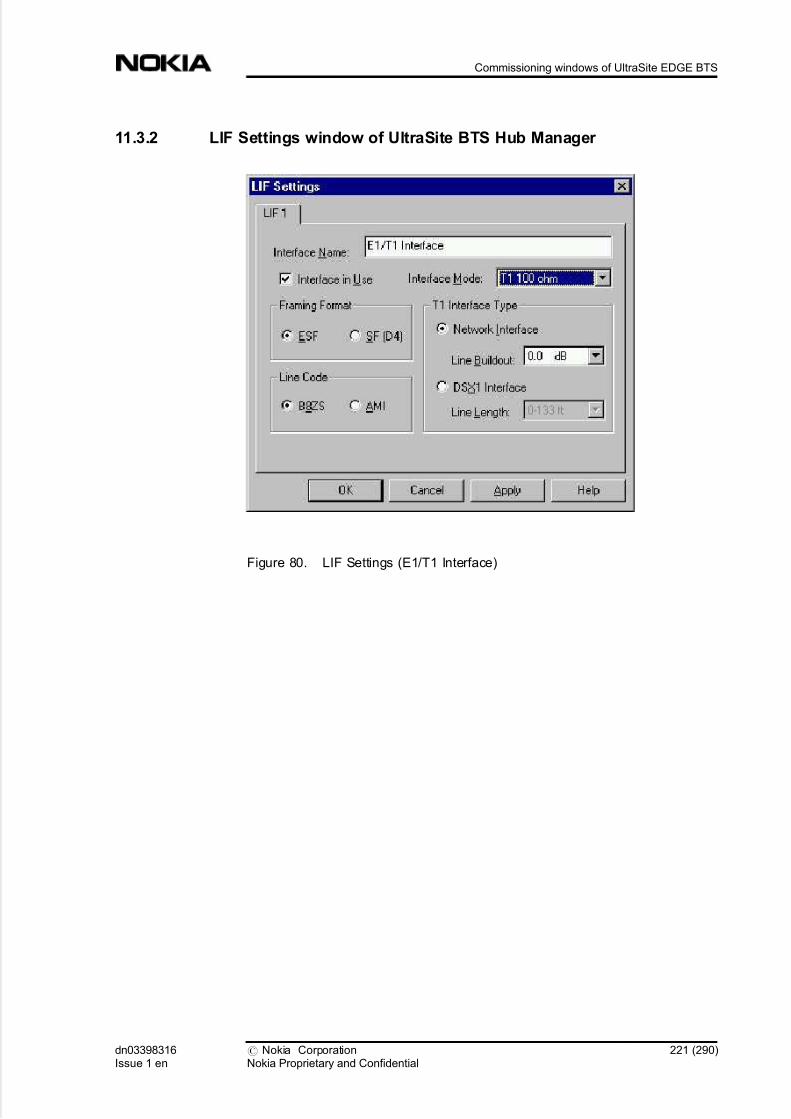
5/14/2018 Commissioning Ultrasite EDGE BTS - slidepdf.com
http://slidepdf.com/reader/full/commissioning-ultrasite-edge-bts 221/290
11.3.2 LIF Settings window of UltraSite BTS Hub Manager
Figure 80. LIF Settings (E1/T1 Interface)
dn03398316Issue 1 en
# Nokia CorporationNokia Proprietary and Confidential
221 (290)
Commissioning windows of UltraSite EDGE BTS

5/14/2018 Commissioning Ultrasite EDGE BTS - slidepdf.com
http://slidepdf.com/reader/full/commissioning-ultrasite-edge-bts 222/290
11.3.3 LIF Settings window for T1 100 ohm mode of UltraSite BTS HubManager
Figure 81. LIF Settings window for T1 100 ohm mode of UltraSite BTS Hub
Manager - FXC
222 (290) # Nokia CorporationNokia Proprietary and Confidential
dn03398316Issue 1 en
Commissioning UltraSite EDGE BTS

5/14/2018 Commissioning Ultrasite EDGE BTS - slidepdf.com
http://slidepdf.com/reader/full/commissioning-ultrasite-edge-bts 223/290
Figure 82. LIF Settings for FC E1/T1 unit in T1 mode
dn03398316Issue 1 en
# Nokia CorporationNokia Proprietary and Confidential
223 (290)
Commissioning windows of UltraSite EDGE BTS

5/14/2018 Commissioning Ultrasite EDGE BTS - slidepdf.com
http://slidepdf.com/reader/full/commissioning-ultrasite-edge-bts 224/290
11.3.4 Unit settings with FXC RRI unit setting window of UltraSite BTS HubManager
Figure 83. Unit settings with FXC RRI unit setting window of UltraSite BTS Hub
Manager
224 (290) # Nokia CorporationNokia Proprietary and Confidential
dn03398316Issue 1 en
Commissioning UltraSite EDGE BTS

5/14/2018 Commissioning Ultrasite EDGE BTS - slidepdf.com
http://slidepdf.com/reader/full/commissioning-ultrasite-edge-bts 225/290
11.3.5 Platform interface tab of settings window of UltraSite BTS HubManager
Figure 84. Platform interface tab
dn03398316Issue 1 en
# Nokia CorporationNokia Proprietary and Confidential
225 (290)
Commissioning windows of UltraSite EDGE BTS

5/14/2018 Commissioning Ultrasite EDGE BTS - slidepdf.com
http://slidepdf.com/reader/full/commissioning-ultrasite-edge-bts 226/290
11.3.6 Flexbus Settings window of RRI Manager
Figure 85. Flexbus settings with FXC RRI card
226 (290) # Nokia CorporationNokia Proprietary and Confidential
dn03398316Issue 1 en
Commissioning UltraSite EDGE BTS

5/14/2018 Commissioning Ultrasite EDGE BTS - slidepdf.com
http://slidepdf.com/reader/full/commissioning-ultrasite-edge-bts 227/290
11.3.7 Flexbus 1 - FlexiHopper Settings window of RRI Manager
Figure 86. Flexbus 1 settings for FlexiHopper outdoor unit
dn03398316Issue 1 en
# Nokia CorporationNokia Proprietary and Confidential
227 (290)
Commissioning windows of UltraSite EDGE BTS

5/14/2018 Commissioning Ultrasite EDGE BTS - slidepdf.com
http://slidepdf.com/reader/full/commissioning-ultrasite-edge-bts 228/290
11.3.8 Flexbus 2 - MetroHopper General Settings window of RRI Manager
Figure 87. Flexbus 2 settings for MetroHopper outdoor unit
228 (290) # Nokia CorporationNokia Proprietary and Confidential
dn03398316Issue 1 en
Commissioning UltraSite EDGE BTS

5/14/2018 Commissioning Ultrasite EDGE BTS - slidepdf.com
http://slidepdf.com/reader/full/commissioning-ultrasite-edge-bts 229/290
11.3.9 Flexbus 2 - MetroHopper Manual Channel Selection window of RRIManager
Figure 88. MetroHopper manual channel selection
dn03398316Issue 1 en
# Nokia CorporationNokia Proprietary and Confidential
229 (290)
Commissioning windows of UltraSite EDGE BTS

5/14/2018 Commissioning Ultrasite EDGE BTS - slidepdf.com
http://slidepdf.com/reader/full/commissioning-ultrasite-edge-bts 230/290
11.3.10 Summary of Commissioning Settings window of RRI Manager
Figure 89. Summary of Commissioning Settings
230 (290) # Nokia CorporationNokia Proprietary and Confidential
dn03398316Issue 1 en
Commissioning UltraSite EDGE BTS

5/14/2018 Commissioning Ultrasite EDGE BTS - slidepdf.com
http://slidepdf.com/reader/full/commissioning-ultrasite-edge-bts 231/290
11.3.11 Monitoring Hop window of UltraSite BTS Hub Manager
Figure 90. Monitoring Hop status
dn03398316Issue 1 en
# Nokia CorporationNokia Proprietary and Confidential
231 (290)
Commissioning windows of UltraSite EDGE BTS

5/14/2018 Commissioning Ultrasite EDGE BTS - slidepdf.com
http://slidepdf.com/reader/full/commissioning-ultrasite-edge-bts 232/290
11.3.12 Synchronisation window
Figure 91. Synchronisation
11.3.13 Add EOC window of UltraSite BTS Hub Manager
Figure 92. Add EOC
232 (290) # Nokia CorporationNokia Proprietary and Confidential
dn03398316Issue 1 en
Commissioning UltraSite EDGE BTS

5/14/2018 Commissioning Ultrasite EDGE BTS - slidepdf.com
http://slidepdf.com/reader/full/commissioning-ultrasite-edge-bts 233/290
11.3.14 Traffic Manager window of UltraSite BTS Hub Manager
Figure 93. Traffic Manager for an E1 link
dn03398316Issue 1 en
# Nokia CorporationNokia Proprietary and Confidential
233 (290)
Commissioning windows of UltraSite EDGE BTS

5/14/2018 Commissioning Ultrasite EDGE BTS - slidepdf.com
http://slidepdf.com/reader/full/commissioning-ultrasite-edge-bts 234/290
11.3.15 Add Cross-connection Wizard - TX1/RX1 window of UltraSite BTSHub Manager
Figure 94. Add Cross-connection Wizard - TX1/RX1
234 (290) # Nokia CorporationNokia Proprietary and Confidential
dn03398316Issue 1 en
Commissioning UltraSite EDGE BTS
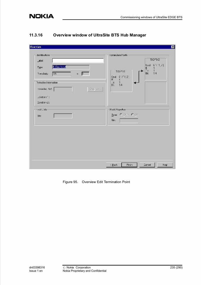
5/14/2018 Commissioning Ultrasite EDGE BTS - slidepdf.com
http://slidepdf.com/reader/full/commissioning-ultrasite-edge-bts 235/290
11.3.16 Overview window of UltraSite BTS Hub Manager
Figure 95. Overview Edit Termination Point
dn03398316Issue 1 en
# Nokia CorporationNokia Proprietary and Confidential
235 (290)
Commissioning windows of UltraSite EDGE BTS

5/14/2018 Commissioning Ultrasite EDGE BTS - slidepdf.com
http://slidepdf.com/reader/full/commissioning-ultrasite-edge-bts 236/290
11.3.17 OutdoorUnit1 - FlexiHopper window of UltraSite BTS Hub Manager
Figure 96. FlexiHopper settings for Outdoor Unit in FXC RRI
236 (290) # Nokia CorporationNokia Proprietary and Confidential
dn03398316Issue 1 en
Commissioning UltraSite EDGE BTS

5/14/2018 Commissioning Ultrasite EDGE BTS - slidepdf.com
http://slidepdf.com/reader/full/commissioning-ultrasite-edge-bts 237/290
11.3.18 RF tab of OutdoorUnit1 - MetroHopper window of UltraSite BTS HubManager
Figure 97. OutdoorUnit1 - MetroHopper RF settings
dn03398316Issue 1 en
# Nokia CorporationNokia Proprietary and Confidential
237 (290)
Commissioning windows of UltraSite EDGE BTS
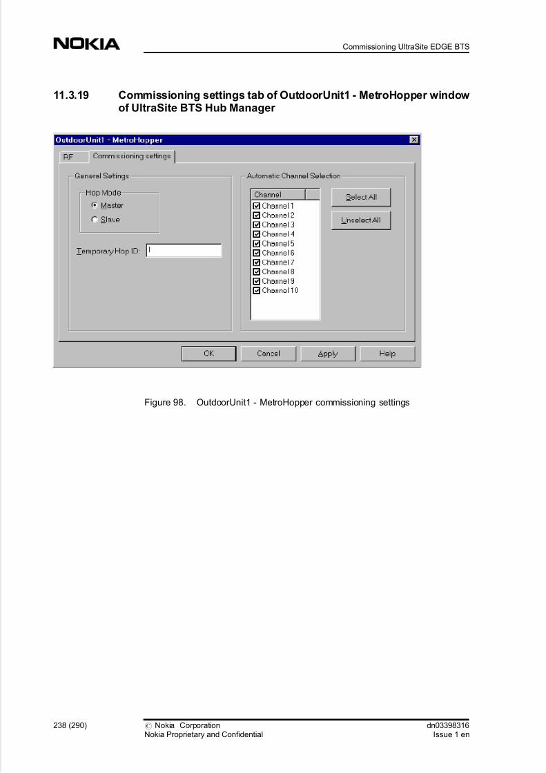
5/14/2018 Commissioning Ultrasite EDGE BTS - slidepdf.com
http://slidepdf.com/reader/full/commissioning-ultrasite-edge-bts 238/290
11.3.19 Commissioning settings tab of OutdoorUnit1 - MetroHopper window of UltraSite BTS Hub Manager
Figure 98. OutdoorUnit1 - MetroHopper commissioning settings
238 (290) # Nokia CorporationNokia Proprietary and Confidential
dn03398316Issue 1 en
Commissioning UltraSite EDGE BTS

5/14/2018 Commissioning Ultrasite EDGE BTS - slidepdf.com
http://slidepdf.com/reader/full/commissioning-ultrasite-edge-bts 239/290
11.3.20 Welcome window of UltraSite BTS Hub Commissioning Wizard
Figure 99. Welcome
dn03398316Issue 1 en
# Nokia CorporationNokia Proprietary and Confidential
239 (290)
Commissioning windows of UltraSite EDGE BTS

5/14/2018 Commissioning Ultrasite EDGE BTS - slidepdf.com
http://slidepdf.com/reader/full/commissioning-ultrasite-edge-bts 240/290
11.3.21 Testing window of UltraSite BTS Hub Commissioning Wizard
Figure 100. Testing
240 (290) # Nokia CorporationNokia Proprietary and Confidential
dn03398316Issue 1 en
Commissioning UltraSite EDGE BTS

5/14/2018 Commissioning Ultrasite EDGE BTS - slidepdf.com
http://slidepdf.com/reader/full/commissioning-ultrasite-edge-bts 241/290
11.3.22 Accept Site Selection (File/Site ID/Site) window of UltraSite BTS HubCommissioning Wizard
Figure 101. Accept Site Selection (File/Site ID/Site)
dn03398316Issue 1 en
# Nokia CorporationNokia Proprietary and Confidential
241 (290)
Commissioning windows of UltraSite EDGE BTS

5/14/2018 Commissioning Ultrasite EDGE BTS - slidepdf.com
http://slidepdf.com/reader/full/commissioning-ultrasite-edge-bts 242/290
11.3.23 Accept Site Selection (Expected Equipment) window of UltraSiteBTS Hub Commissioning Wizard
Figure 102. Accept Site Selection (Expected Equipment)
242 (290) # Nokia CorporationNokia Proprietary and Confidential
dn03398316Issue 1 en
Commissioning UltraSite EDGE BTS

5/14/2018 Commissioning Ultrasite EDGE BTS - slidepdf.com
http://slidepdf.com/reader/full/commissioning-ultrasite-edge-bts 243/290
11.3.24 Check Hops window of UltraSite BTS Hub Commissioning Wizard
Figure 103. Check Hops
dn03398316Issue 1 en
# Nokia CorporationNokia Proprietary and Confidential
243 (290)
Commissioning windows of UltraSite EDGE BTS

5/14/2018 Commissioning Ultrasite EDGE BTS - slidepdf.com
http://slidepdf.com/reader/full/commissioning-ultrasite-edge-bts 244/290
11.3.25 End window of UltraSite BTS Hub Commissioning Wizard
Figure 104. End
244 (290) # Nokia CorporationNokia Proprietary and Confidential
dn03398316Issue 1 en
Commissioning UltraSite EDGE BTS
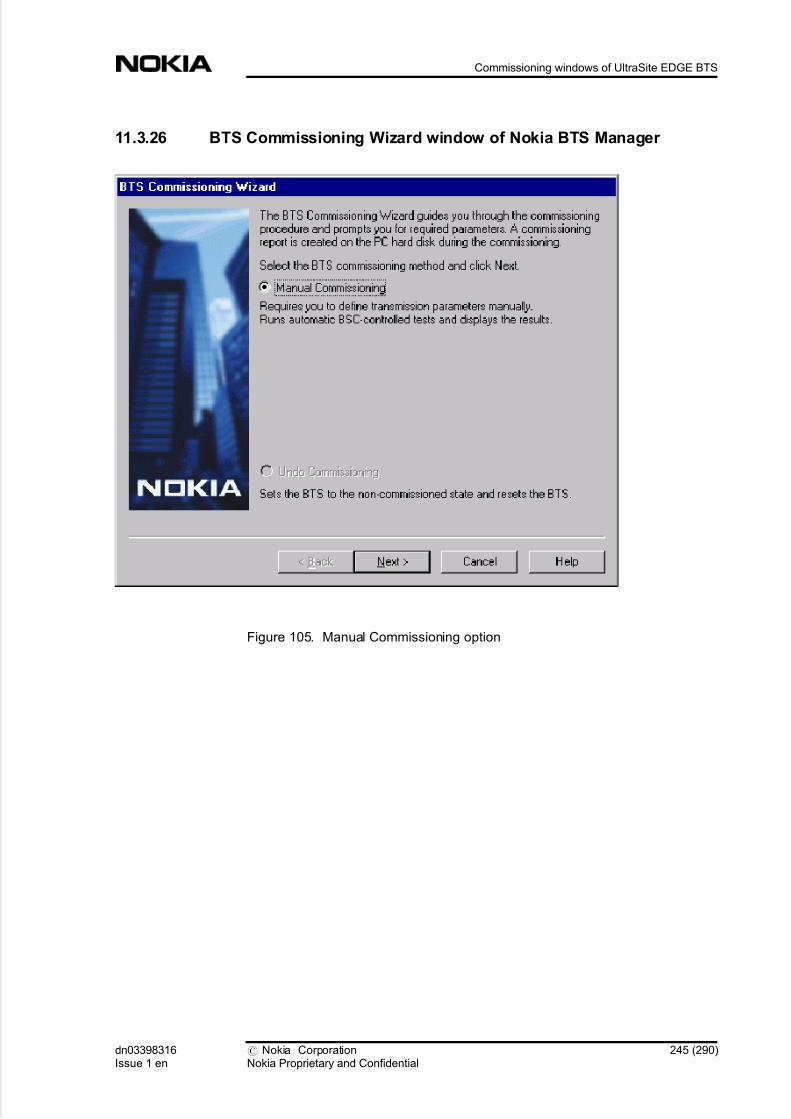
5/14/2018 Commissioning Ultrasite EDGE BTS - slidepdf.com
http://slidepdf.com/reader/full/commissioning-ultrasite-edge-bts 245/290
11.3.26 BTS Commissioning Wizard window of Nokia BTS Manager
Figure 105. Manual Commissioning option
dn03398316Issue 1 en
# Nokia CorporationNokia Proprietary and Confidential
245 (290)
Commissioning windows of UltraSite EDGE BTS

5/14/2018 Commissioning Ultrasite EDGE BTS - slidepdf.com
http://slidepdf.com/reader/full/commissioning-ultrasite-edge-bts 246/290
11.3.27 Set Transmission Parameters window of BTS CommissioningWizard
Figure 106. Set Transmission Parameters - FC unit
246 (290) # Nokia CorporationNokia Proprietary and Confidential
dn03398316Issue 1 en
Commissioning UltraSite EDGE BTS

5/14/2018 Commissioning Ultrasite EDGE BTS - slidepdf.com
http://slidepdf.com/reader/full/commissioning-ultrasite-edge-bts 247/290
11.3.28 Transmission configuration window of BTS Commissioning Wizard
Figure 107. Transmission Configuration page for FXC E1(/T1) unit
dn03398316Issue 1 en
# Nokia CorporationNokia Proprietary and Confidential
247 (290)
Commissioning windows of UltraSite EDGE BTS

5/14/2018 Commissioning Ultrasite EDGE BTS - slidepdf.com
http://slidepdf.com/reader/full/commissioning-ultrasite-edge-bts 248/290
11.3.29 BTS Test Reporting window of BTS Commissioning Wizard
Figure 108. Test events
248 (290) # Nokia CorporationNokia Proprietary and Confidential
dn03398316Issue 1 en
Commissioning UltraSite EDGE BTS

5/14/2018 Commissioning Ultrasite EDGE BTS - slidepdf.com
http://slidepdf.com/reader/full/commissioning-ultrasite-edge-bts 249/290
11.3.30 EAC Input Settings window of BTS Commissioning Wizard
Figure 109. EAC inputs
dn03398316Issue 1 en
# Nokia CorporationNokia Proprietary and Confidential
249 (290)
Commissioning windows of UltraSite EDGE BTS

5/14/2018 Commissioning Ultrasite EDGE BTS - slidepdf.com
http://slidepdf.com/reader/full/commissioning-ultrasite-edge-bts 250/290
11.3.31 EAC Output Settings window of BTS Commissioning Wizard
Figure 110. EAC outputs
250 (290) # Nokia CorporationNokia Proprietary and Confidential
dn03398316Issue 1 en
Commissioning UltraSite EDGE BTS

5/14/2018 Commissioning Ultrasite EDGE BTS - slidepdf.com
http://slidepdf.com/reader/full/commissioning-ultrasite-edge-bts 251/290
11.3.32 BTS Commissioning Report window of BTS Commissioning Wizard
Figure 111. BTS Commissioning Report
dn03398316Issue 1 en
# Nokia CorporationNokia Proprietary and Confidential
251 (290)
Commissioning windows of UltraSite EDGE BTS

5/14/2018 Commissioning Ultrasite EDGE BTS - slidepdf.com
http://slidepdf.com/reader/full/commissioning-ultrasite-edge-bts 252/290
11.3.33 Sychronization window of UltraSite BTS Hub manager
Figure 112. Synchronization settings for FC E1/T1 unit
252 (290) # Nokia CorporationNokia Proprietary and Confidential
dn03398316Issue 1 en
Commissioning UltraSite EDGE BTS

5/14/2018 Commissioning Ultrasite EDGE BTS - slidepdf.com
http://slidepdf.com/reader/full/commissioning-ultrasite-edge-bts 253/290
12 Glossary
12.1 Glossary for UltraSite EDGE BTS
12.1.1 Abbreviations and acronyms
This section lists abbreviations and acronyms used throughout Nokia UltraSite
EDGE Solution documentation.
AC Alternating Current
ACFU AC Filter Unit
A/D Analog/Digital
ADC Analog to Digital Converter
ADUA AC/DC control and distribution unit for Integrated Battery
Backup (IBBU)
AGC Automatic Gain Control
ALS Automatic Laser Shutdown
AMR Adaptive Multi-Rate coding
ANSI American National Standards Institute
ANT Antenna connector
ARFN Absolute Radio Frequency Channel Number
ASIC Application Specific Integrated Circuit
ATM Asynchronous Transfer Mode
dn03398316Issue 1 en
# Nokia CorporationNokia Proprietary and Confidential
253 (290)
Glossary

5/14/2018 Commissioning Ultrasite EDGE BTS - slidepdf.com
http://slidepdf.com/reader/full/commissioning-ultrasite-edge-bts 254/290
AWG American Wire Gauge
AXC ATM cross-connect
AXU ATM cross-connect unit
BAPT Bundesamt für Post und Telekommunikation
Telecommunications advisory agency of Federal Republic of
Germany
BATx Rectifier for battery backup
BBAG 12 V battery for Integrated Battery Backup (IBBU)
BB2x Transceiver Baseband unit . BB2A for GSM
. BB2E for GSM/EDGE
BCCH Broadcast Control Channel
BCF Base Control Function
BER Bit Error Ratio
The ratio of the number of bit errors to the total number of
bits transmitted in a given time interval.
BIST Built-In Self Test
A technique that provides a circuit the capability to carry out
an implicit test of itself.
BOIx Base Operations and Interfaces unit
BPxN Bias Tee without VSWR monitoring
.
BPDN for GSM 900/1800/1900. BPxV Bias Tee with VSWR monitoring
. BPGV for GSM 900
. BPDV for GSM 1800/1900
BS British Standards
BSC Base Station Controller
254 (290) # Nokia CorporationNokia Proprietary and Confidential
dn03398316Issue 1 en
Commissioning UltraSite EDGE BTS

5/14/2018 Commissioning Ultrasite EDGE BTS - slidepdf.com
http://slidepdf.com/reader/full/commissioning-ultrasite-edge-bts 255/290
BSS Base Station Subsystem
BTS Base Transceiver Station (Base Station)
CC Cross-Connection
CCCH Common Control Channel
CCITT Comité Consultatif International Télégraphique et
Téléphonique
International Telegraph and Telephone Consultative
Committee (Telecommunications advisory agency of France)
CCUA Cabinet Control Unit
CDMA Code Division Multiple Access
A technique in which the radio transmissions using the same
frequency band are coded in a way that a signal from a certain
transmitter can be received only by certain receivers
CE Cable Entry; Consumer Electronics; Conformit Européen
(European Conformity) CH Channel
CHDSP Channel Digital Signal Processor
CN Change Note
A short trouble management document in a specified form
sent to a customer about a modification in a product
CRC Cyclic Redundancy Check
A method for detecting errors in data transmission.
CRMx Core Mechanics for Nokia UltraSite EDGE Base StationIndoor and Outdoor cabinet
. CRMA for Indoor and Outdoor cabinets
. CRMB for Site Support cabinets
. CRMC for Midi Indoor and Outdoor cabinets
CSC Customer Services Centre
D/A Digital/Analog
dn03398316Issue 1 en
# Nokia CorporationNokia Proprietary and Confidential
255 (290)
Glossary
5/14/2018 Commissioning Ultrasite EDGE BTS - slidepdf.com
http://slidepdf.com/reader/full/commissioning-ultrasite-edge-bts 256/290
DC Direct Current
DCS Digital Cellular System
DDS Direct Digital Synthesis
The frequency synthesis in which logic and memory are used
to digitally construct the desired output signal, and a digital-
to-analogue converter is used.
DL (Downlink)
The direction of transmission in which the BTS is the
transmitting facility and the mobile station is the receiving
facility.
DIP Dual In-line Package
DRAM Dynamic Random Access Memory
DRX Discontinuous Reception
DSP Digital Signal Processor
DTX Discontinuous Transmission
DU2A Dual Band Diplex Filter unit for GSM 900/1800
DVxx Dual Variable Gain Duplex Filter unit
. DVTB for GSM/EDGE 800
. DVTC for GSM/EDGE 800 co-siting
. DVGA for GSM/EDGE 900
. DVHA for GSM/EDGE 900 customer-specific H band
. DVJA for GSM/EDGE 900 customer-specific J band
. DVDC for GSM/EDGE 1800
. DVDA for GSM/EDGE 1800 A band
. DVDB for GSM/EDGE 1800 B band
. DVPA for GSM/EDGE 1900
E1 European Digital Transmission Format Standard (2.048 Mbit/
s)
EAC External Alarms and Controsl
256 (290) # Nokia CorporationNokia Proprietary and Confidential
dn03398316Issue 1 en
Commissioning UltraSite EDGE BTS

5/14/2018 Commissioning Ultrasite EDGE BTS - slidepdf.com
http://slidepdf.com/reader/full/commissioning-ultrasite-edge-bts 257/290
EC European Community
EDGE Enhanced Data rates for Global Evolution
EEC European Economic Community
EEPROM Electronically Erasable Programmable Read Only Memory
EMC Electromagnetic Compatibility
EMI Electromagnetic Interference
EMP Electromagnetic Pulse
EN European Norm
EQDSP Equaliser Digital Signal Processor
ESD Electrostatic Discharge
ET Exchange Terminal
ETSI European Telecommunications Standards Institute
Ext. External
FACCH Fast Associated Control Channel
FACH Forward Access Channel
FCC Federal Communications Commission
The United States federal agency responsible for the
regulation of interstate and international communications by
radio, television, wire, satellite, and cable.
FC E1/T1 Wireline transmission unit (75 [ohm] E1, 120 [ohm] E1, or 100 [ohm] T1) of Nokia UltraSite EDGE Base Station
without cross-connection capability.
FCLK Frame Clock
FET Field Effect Transistor
FHS Frequency Hopping Synthesiser
dn03398316Issue 1 en
# Nokia CorporationNokia Proprietary and Confidential
257 (290)
Glossary

5/14/2018 Commissioning Ultrasite EDGE BTS - slidepdf.com
http://slidepdf.com/reader/full/commissioning-ultrasite-edge-bts 258/290
FIFP Forwarded Intermediate Frequency Power
FIKA +24 VDC Installation Kit
FPGA Field Programmable Gate Array
FXC E1 Wireline transmission unit (75 [ohm] E1) with four line
interfaces to the 2 Mbit/s (E1) transmission line; cross-
connection capability at 8 kbit/s level.
FXC E1/T1 Wireline transmission unit (120 [ohm] E1 or 100 [ohm] T1)
with four line interfaces to the 2 Mbit/s (E1) or 1.5 Mbit/s
(T1) transmission line; cross-connection capability at 8 kbit/s
level.
FXC RRI Radio link transmission unit (radio indoor unit) with cross-
connection capability at 8 kbit/s level.
Used with MetroHopper Radio and FlexiHopper Microwave
Radio.
Gb Interface between RNC and SGSN
GMSK Gaussian Minimum Shift Keying
GND Ground; Grounding (protective earthing).
See Grounding and PE.
GPRS General Packet Radio Service
GSM Global System for Mobile communications
. GSM 800 GSM 800 MHz frequency band
. GSM 900 GSM 900 MHz frequency band
. GSM 1800 GSM 1800 MHz frequency band
.
GSM 1900 GSM 1900 MHz frequency band
GUI Graphical User Interface
HDLC High-level Data Link Control
HETA Base station cabinet heater
HO Handover
258 (290) # Nokia CorporationNokia Proprietary and Confidential
dn03398316Issue 1 en
Commissioning UltraSite EDGE BTS

5/14/2018 Commissioning Ultrasite EDGE BTS - slidepdf.com
http://slidepdf.com/reader/full/commissioning-ultrasite-edge-bts 259/290
The action of switching a call in progress from one radio
channel to another, to secure the continuity of the established
call
HSCSD High-Speed Circuit Switched Data
HV High Voltage
HW Hardware
Specfically, electronic equipment supporting data
transmission and processing tasks, and the electrical and
mechanical devices related to their operation
IAKx Indoor Application Kit for Nokia UltraSite EDGE Base
Station
. IAKA for UltraSite Indoor cabinet
. IAKC for UltraSite Midi Indoor cabinet
IBBU Integrated Battery Backup
IC Integrated Cell
ICE Intelligent Coverage Enhancement
ID Identification; Identifier IE Information Element
The basic unit of a transaction capabilities application part
(TCAP) message.
IEC International Electrotechnical Commission
IEEE Institute of Electrical and Electronics Engineers, Inc.
IF Intermediate Frequency
IFM Interface Module
IFU Interface unit
ILKA Indoor Lock Kit
ILMT Integrated Local Management Tool
dn03398316Issue 1 en
# Nokia CorporationNokia Proprietary and Confidential
259 (290)
Glossary

5/14/2018 Commissioning Ultrasite EDGE BTS - slidepdf.com
http://slidepdf.com/reader/full/commissioning-ultrasite-edge-bts 260/290
IMA Inverse Multiplexed ATM
IP Ingress Protection
IRPA International Radiation Protection Association
ISDN Integrated Services Digital Network
ISHO Inter-system handover
The handover from one system to another.
ISO International Organization for Standardization
ITU International Telecommunication Union
L2 AC Phase 2
L3 AC Phase 3
Iu The interconnection point between the RNC and the Core
Network
Iub Interface between the RNC and node B
Iubis Interface between the RNC and the BTS
Iur The logical interface for the interconnection of two radio
network controller (RNC) components of the UMTS
terrestrial radio access network (UTRAN) system
JIS Japanese Industrial Standard
LAN Local Area Network
A data transmission network covering a small area.
LAPD Link Access Protocol on D-channel between the BSC and
BTS
LED Light Emitting Diode
LMB Local Management Bus
LMP Local Management Port
260 (290) # Nokia CorporationNokia Proprietary and Confidential
dn03398316Issue 1 en
Commissioning UltraSite EDGE BTS

5/14/2018 Commissioning Ultrasite EDGE BTS - slidepdf.com
http://slidepdf.com/reader/full/commissioning-ultrasite-edge-bts 261/290
LNA Low-Noise Amplifier
LO Local Oscillator
LTE Line Terminal Equipment
LV Low Voltage
LVD Low Voltage Disconnect
LVDS Low Voltage Differential Signalling
LVTTL Low Voltage Transistor Transistor Logic
M2xA 2-way Receiver Multicoupler unit . M2LA for GSM/EDGE 800/900
. M2HA for GSM/EDGE 1800/1900
. M6xA 6-way Receiver Multicoupler unit
. M6LA for GSM/EDGE 800/900
. M6HA for GSM/EDGE 1800/1900
MAC Medium Access Control function, handles the channel
allocation and multiplexing, that is, the use of physical layer
functions.
MCLG Master Clock Generator
MDF Main Distribution Frame
MHA Masthead Amplifier
MMI Man-Machine Interface
MML Man-Machine Language
A text-based command language with a standardisedstructure, designed to facilitate direct user control of a system.
MNxx Masthead Amplifier specific to Nokia UltraSite EDGE Base
Station
. MNGA for GSM/EDGE 800/900
. MNDA for GSM/EDGE 1800 A band
. MNDB for GSM/EDGE 1800 B band
dn03398316Issue 1 en
# Nokia CorporationNokia Proprietary and Confidential
261 (290)
Glossary

5/14/2018 Commissioning Ultrasite EDGE BTS - slidepdf.com
http://slidepdf.com/reader/full/commissioning-ultrasite-edge-bts 262/290
. MNPA for GSM/EDGE 1900 A band
. MNPB for GSM/EDGE 1900 B band
. MNPC for GSM/EDGE 1900 C band
MPT Ministry of Posts and Telecommunications
Telecommunications regulatory agency of Great Britain.
MS Mobile Station
User equipment which uses a radio connection, and which can
be used in motion or at unspecified points. This is usually a
mobile phone.
MSC Mobile Switching Centre
The mobile network element which performs the switching
functions in its area of operation, and controls cooperation
with other networks.
MTBF Mean Time Between Failure
NCRP National Council on Radiation Protection and Measurements
NCU Node Control Unit
NEBS Network Equipment Building Systems
NED Nokia Electronic Documentation
NMS Network Management System
O&M Operation and Maintenance
OAKB Cable entry kit for BTS co-siting
OAKx Outdoor Application Kit for Nokia UltraSite EDGE BaseStation
. OAKA for UltraSite Outdoor cabinet
. OAKC for UltraSite Midi Outdoor cabinet
. OAKD for UltraSite Midi Outdoor to Talk-family Co-
siting
OBKA Outdoor Bridge Kit
262 (290) # Nokia CorporationNokia Proprietary and Confidential
dn03398316Issue 1 en
Commissioning UltraSite EDGE BTS

5/14/2018 Commissioning Ultrasite EDGE BTS - slidepdf.com
http://slidepdf.com/reader/full/commissioning-ultrasite-edge-bts 263/290
OCXO Oven Controlled Crystal Oscillator
An oscillator in which the crystal and critical circuits are
temperature-controlled by an oven.
OEKA Outdoor (cable) Entry Kit
OFKA Outdoor Air Filter Kit
OFKC MIDI Outdoor Air Filter Kit
OMU Operation and Maintenance Unit
OMUSIG OMU Signalling
OVP Over-Voltage Protection
PC Personal Computer
PCB Printed Circuit Board
PCM Pulse Code Modulation
PE Protective earthing (grounding)
See GND and Grounding.
PFC Power Factor Correction
PLL Phase-Locked Loop
Point-to-point Transmission between two fixed points
PSM Power System Management
PWM Pulse Width Modulation
PWSx AC/DC Power Supply unit
. PWSA for 230 VAC input
. PWSB for -48 VDC input
. PWSC for +24 VDC input
Q1 Nokia proprietary transmission management protocol
dn03398316Issue 1 en
# Nokia CorporationNokia Proprietary and Confidential
263 (290)
Glossary

5/14/2018 Commissioning Ultrasite EDGE BTS - slidepdf.com
http://slidepdf.com/reader/full/commissioning-ultrasite-edge-bts 264/290
RACH Random Access Channel
RAKE A receiver capable of receiving and combining multipath
signals
RAM Random Access Memory
RAN Radio Access Network
A third generation network that provides mobile access to a
number of core networks of both mobile and fixed origin.
RCD Residual Current Device
RF Radio Frequency
RFF Radio Frequency Fingerprinting
RIFP Reflected Intermediate Frequency Power
RLE Radio Link Equipment
RNC Radio Network Controller
The network element in a radio access network which is in
charge of the use and the integrity of radio resources.
ROM Read Only Memory
RRI Radio Relay Interface
RSSI Received Signal Strength Indicator
RTC Remote Tune Combining
RTxx Remote Tune Combiner
. RTGA for GSM/EDGE 900
. RTHA for GSM/EDGE 900 H band
. RTJA for GSM/EDGE 900 J band
. RTDC for GSM/EDGE 1800
. RTDA for GSM/EDGE 1800 A band
. RTDB for GSM/EDGE 1800 B band
. RTPA for GSM/EDGE 1900
264 (290) # Nokia CorporationNokia Proprietary and Confidential
dn03398316Issue 1 en
Commissioning UltraSite EDGE BTS
5/14/2018 Commissioning Ultrasite EDGE BTS - slidepdf.com
http://slidepdf.com/reader/full/commissioning-ultrasite-edge-bts 265/290
RTN Return
RX Receiver; Receive
SCF Site Configuration File
SCT Site Configuration Tool
SDCCH Stand-alone Dedicated Control Channel
SDH Synchronous Digital Hierarchy
SMB Sub-Miniature B Connector
SMS Short Message Service
SSS Site Support System
STM Synchronous Transport Module
STM-1 Synchronous Transport Module (155 Mbit/s)
SW Software
Sync Synchronization
The process of adjusting corresponding significant instances
of signals, in order to obtain the desired phase relationship
between these instances.
T1 North American Digital Transmission Format Standard (1.544
Mbit/s)
TC Transcoder
TCH Traffic Channel
The logical radio channel that is assigned to a base transceiver
station and is primarily intended for conversation.
TCP/IP Transport Control Protocol/Internet Protocol
TCS Temperature Control System
TDMA Time Division Multiple Access
dn03398316Issue 1 en
# Nokia CorporationNokia Proprietary and Confidential
265 (290)
Glossary

5/14/2018 Commissioning Ultrasite EDGE BTS - slidepdf.com
http://slidepdf.com/reader/full/commissioning-ultrasite-edge-bts 266/290
TE Terminal Equipment
Equipment that provides the functions necessary for user
operation of the access protocols.
TMS Transmission Management System
The network system for managing equipment settings, and for
centralised retrieval of statistics and alarm information from
transmission equipment connected to the system.
TS Time Slot
A cyclic time interval that can be recognised and given a
unique definition.
TRE Transmission Equipment
TRX Transceiver
TRXSIG TRX Signalling
TS Time Slot
TSxx Transceiver (RF unit), specific to Nokia UltraSite EDGE Base
Station
. TSTB for GSM/EDGE 800
. TSGA for GSM 900
. TSGB for GSM/EDGE 900
. TSDA for GSM 1800
. TSDB for GSM/EDGE 1800
. TSPA for GSM 1900
. TSPB for GSM/EDGE 1900
TTL Transistor Transistor Logic
TX Transmitter; Transmit
UC Unit Controller
UI User Interface
UL Underwriters Laboratories
266 (290) # Nokia CorporationNokia Proprietary and Confidential
dn03398316Issue 1 en
Commissioning UltraSite EDGE BTS

5/14/2018 Commissioning Ultrasite EDGE BTS - slidepdf.com
http://slidepdf.com/reader/full/commissioning-ultrasite-edge-bts 267/290
UL (Uplink) The direction of transmission in which the mobile station is
the transmitting facility and the BTS is the receiving facility.
. 2-way uplink diversity - The function by which a BTS
uses two antennas and two receivers simultaneously ona single channel to obtain improved overall BTS
receiver sensitivity in an environment that is subject to
random multipath fading.
. 4-way uplink diversity - The function by which a BTS
uses four antennas and four receivers simultaneously
on a single channel to obtain improved overall BTS
receiver sensitivity in an environment that is subject to
random multipath fading.
UMTS Universal Mobile Telecommunications System
UTRAN / UMTS
Terrestrial Radio Access Network
A radio access network (RAN) consisting of radio network
controllers (RNCs) and base transceiver stations (BTSs). It is
located between the Iu interface and the wideband code
division multiple access (WCDMA) radio interface.
UPS Uninterruptible Power Supply
VC Virtual Channel
VCO Voltage Controlled Oscillator
An oscillator for which a change in tuning voltage results in a
predetermined change in output frequency.
VLL Line-to-Line Voltage
VP Virtual Path
The unidirectional transport of ATM cells belonging to virtualchannels that are associated by a common identifier value.
VPCI Virtual Path Connection Identifier
An identifier which identifies the virtual path connection
between two B-ISDN ATM exchanges, or between a B-ISDN
ATM exchange and a B-ISDN user.
dn03398316Issue 1 en
# Nokia CorporationNokia Proprietary and Confidential
267 (290)
Glossary

5/14/2018 Commissioning Ultrasite EDGE BTS - slidepdf.com
http://slidepdf.com/reader/full/commissioning-ultrasite-edge-bts 268/290
VPI Virtual Path Identifier
An identifier which identifies a group of virtual channel links
at a given reference point that share the same virtual pathconnection.
VSWR Voltage Standing Wave Ratio
The ratio of maximum to minimum voltage in the standing
wave pattern that appears along a transmission line. It is used
as a measure of impedance mismatch between the
transmission line and its load.
VXxx Transmission unit, specific to Nokia UltraSite EDGE Base
Station
. VXEA for FC E1/T1
. VXRA for FC RRI
. VXRB for FXC RRI
. VXTA for FXC E1
. VXTB for FXC E1/T1
WAF Wideband Antenna Filter unit
WAM
Wideband Application Manager unit
WBC Wideband Combining unit
WCC Wideband Cabinet Core
WCDMA Wide band Code Division Multiple Access
A spread spectrum CDMA technique used to increase the
capacity and coverage of wireless communication networks.
WCH Wideband Cabinet Heater
WCxA Wideband Combiner, specific to Nokia UltraSite EDGE Base
Station
. WCGA for GSM/EDGE 800/900
. WCDA for GSM/EDGE 1800
. WCPA for GSM/EDGE 1900
268 (290) # Nokia CorporationNokia Proprietary and Confidential
dn03398316Issue 1 en
Commissioning UltraSite EDGE BTS

5/14/2018 Commissioning Ultrasite EDGE BTS - slidepdf.com
http://slidepdf.com/reader/full/commissioning-ultrasite-edge-bts 269/290
WEK Wideband Extension Kit
WFA Wideband Fan
WHX Wideband Heat Exchanger
WIC Wideband Input Combiner
WIK Wideband Indoor Kit
WOC Wideband Output Combiner
WOK Wideband Outdoor Kit
WPA Wideband Power Amplifier unit
WPS Wideband Power Supply unit
WSC Wideband System Clock
WSM Wideband Summing and Multiplexing unit
WSP Wideband Signal Processor unit
WTR Wideband Transmitter and Receiver
12.1.2 Terms
This section provides definitions for terms used throughout Nokia UltraSite
Solution documentation.
Abis Interface Interface between a Base Transceiver Station (BTS) and the
Base Station Controller (BSC) and between two BTSs.
Absolute radio frequency channel number
See absolute radio frequency number.
Absolute radio frequency number; absolute radio frequency channel number;
ARFN; ARFCN
Radio frequency used in connection with, for example,
mobile originating and terminating test calls.
Adaptive multi-rate speech codec; AMR speech codec; AMR codec; AMR
Speech codec which adapts its operation optimally according
to the prevailing channel conditions.
dn03398316Issue 1 en
# Nokia CorporationNokia Proprietary and Confidential
269 (290)
Glossary

5/14/2018 Commissioning Ultrasite EDGE BTS - slidepdf.com
http://slidepdf.com/reader/full/commissioning-ultrasite-edge-bts 270/290
Air Interface Interface between MS and BTS.
Alarm Announcement given to the operating personnel about
abnormal functioning of the system or about a failure, or anindication of the degradation of the service level or reliability.
Alarm Status Classification of the severity of an alarm, such as Critical,
Major, Minor, and Information.
Alternating current; AC
A periodic current having a mean value zero.
Analogue-to-digital converter; Analog-to-digital converter /US/; A/D converter;
ADC
A device which converts an analogue input signal to a digital
output signal carrying equivalent information.
Application-specific integrated circuit; custom circuit; custom IC; ASIC
Integrated circuit which is designed for a specific application
and a specific customer and which is not available to other
customers.
ATM connection control; connection control; CC
Function that keeps track of connection resources and based
on those handles the operations related to different kind of
cross-connections.
ATM inverse multiplexing
See inverse multiplexing for ATM.
Backplane Connector board at the back of Nokia UltraSite cabinets to
which plug-in units are directly connected. See also BATA
backplane and RFU backplane.
Base station See base transceiver station.
Base station controller; BSC
Network element in the public land mobile network (PLMN)for controlling one or more base transceiver stations (BTS) in
the call set-up functions, in signalling, in the use of radio
channels and in various maintenance tasks.
Base station system; BSS
System of base stations (BSs) and base station controllers
which is viewed by the mobile services switching centre
(MSC) through a single interface.
270 (290) # Nokia CorporationNokia Proprietary and Confidential
dn03398316Issue 1 en
Commissioning UltraSite EDGE BTS

5/14/2018 Commissioning Ultrasite EDGE BTS - slidepdf.com
http://slidepdf.com/reader/full/commissioning-ultrasite-edge-bts 271/290
Base transceiver station; base station; BTS; BS
Network element in a mobile network responsible for radio
transmission and reception to or from the mobile station.
BATA backplane
Additional backplane required in a Site Support cabinet when
using 12 rectifiers.
Bias Tee Unit that provides DC power for an associated MHA unit.
Cabinet Control Unit
Module of the ADUA or ADUB that manages battery control,
climatic control, alarm reporting, and serial and version
number reporting for the IBBU or Nokia UltraSite Support
cabinet. The CCU connects to the BOIx with Q1-bus.
Cell Coverage area of a given BTS where transmission is
acceptably received.
Cell breathing Variation of the cell coverage area; depends on the
interference and power requirements.
Cellular Network
Two or more base stations connected together to provide an
area of coverage for Mobile Stations (MS).
CENELEC Comité European de Normalisation ELECtrotechnique.European Committee for Electrotechnical Standardization.
Chain Connection
Transmission solution in which the BTSs are interconnected
through a chain, and the first BTS in the chain is connected to
the BSC. See Loop Connection, Multidrop Connection, and
Star Connection.
Chip Signal element.
Chip rate Number of chips transmitted in one second.
Commissioning Tasks performed to enable the BTS to be connected to the
network. Includes operational tests and configuring of the
transmission equipment.
Coverage Area See Cell.
dn03398316Issue 1 en
# Nokia CorporationNokia Proprietary and Confidential
271 (290)
Glossary

5/14/2018 Commissioning Ultrasite EDGE BTS - slidepdf.com
http://slidepdf.com/reader/full/commissioning-ultrasite-edge-bts 272/290
Cross-connection
Connection between input and output ports of a network
element.
Cross-connection bank
Information base that defines the cross-connections of a
network element. The network element contains two or more
banks, one of which is always active.
Custom circuit See application-specific integrated circuit.
Custom IC See application-specific integrated circuit.
D-bus Bus used for traffic communication between the transmission
units and BB2x units (D1-bus) and for internal O&M
communication with the BOIx, BB2x, and RTxx units (D2-
bus).
Despreading The received wideband signal is modulated with the
spreading code to get a narrowband signal after the multipath
propagation in spread spectrum systems.
Digital signal processor; DSP
A processor designed for signal handling, resembling an
ordinary microprocessor.
Discontinuous reception; DRXMeans of saving battery power (for example in hand-portable
units) by periodically and automatically switching the mobile
station receiver on and off.
Discontinuous transmission; DTX
Feature which enables saving battery power (for example in
hand-portable units) and reducing interference by
automatically switching the transmitter off when no speech
or data are to be sent.
Downlink DiversitySee Frequency Hopping.
Earthing See Grounding.
F-bus Frequency Hopping bus. See Frequency Hopping.
Finger; rake finger; RAKE finger
Receiver unit that despreads one multipath signal.
272 (290) # Nokia CorporationNokia Proprietary and Confidential
dn03398316Issue 1 en
Commissioning UltraSite EDGE BTS

5/14/2018 Commissioning Ultrasite EDGE BTS - slidepdf.com
http://slidepdf.com/reader/full/commissioning-ultrasite-edge-bts 273/290
Four-way uplink diversity; 4-way uplink diversity
Function by which a base transceiver station (BTS) uses four
antennas and four receivers simultaneously on a single
channel to obtain improved overall BTS receiver sensitivity
in an environment that is subject to random multipath fading.
Forward link See downlink.
Flash memory Nonvolatile, electronically writable memory, similar to
EEPROM in function, but which must be erased in blocks.
Flexbus Bidirectional coaxial cable that carries up to 16 x 2 Mbit/s
signals and power between transmission equipment, such as a
radio outdoor and indoor unit.
Frequency-change oscillator
See local oscillator.
Frequency Hopping
Function in which a BTS swaps two transmitters on a single
channel to obtain improved overall MS receiver sensitivity in
a system that is subject to random fading.
Gain Signal amplification, expressed in dBi decibels over a
theoretic, isotropic, and uniformly radiating antenna.
Grounding Protecting the equipment and the users against lightning andsurges through the external connections.
I2C-bus Integrated Inter Cell communication bus used for polling,
autodetection, version and serial number management,
temperature polling, and alarm collection in units without a
microprocessor.
Handover The handover occurs between two cells; the signal goes
through one base station or base station sector at a time.
Human-machine interface; man-machine interface; HMI; MMIA subsystem or function which provides user interface
functions in a man-machine language.
Installation Tasks performed to enable the BTS to be mounted at the site.
Integration Tasks performed to make the BTS functional in the cellular
network. Includes making test calls.
dn03398316Issue 1 en
# Nokia CorporationNokia Proprietary and Confidential
273 (290)
Glossary

5/14/2018 Commissioning Ultrasite EDGE BTS - slidepdf.com
http://slidepdf.com/reader/full/commissioning-ultrasite-edge-bts 274/290
Inter-frequency handover
Handover where the new carrier frequency is different from
the current one.
Inter-system handover
Handover from one system to another, e.g. between a 3rd
generation system and GSM.
Inverse multiplexing for ATM; ATM inverse multiplexing; inverse multiplexing;
IMA
The transmission method in which ATM cells in a cell stream
are divided across several physical E1 links on a cell-by-cell
basis, and then reassembled at the receiving end without
affecting the original cell order.
Loop connection
Transmission solution in which BTSs are interconnected in a
loop. For example, the first and last BTSs are connected to the
BSC. See Chain Connection, Multidrop Connection, and Star
Connection.
Macrocellular Application that covers large areas with a cell radius of 1 to
10 km (0.6 to 6 miles). The coverage area is achieved when
the antenna is installed high and off the ground.
Maximum ratio combining
A signal combining technique in which each signal ismultiplied by a weight factor that is proportional to the signal
amplitude: the strong signals are further amplified, while the
weak signals are attenuated.
Microcellular Application that typically covers areas with a cell radius of
100 m to 1 km (327 feet to 0.6 miles). The antennas are
installed below rooftop level.
Microwave radio
Radio equipment for establishing an aligned and fixed radio
connection between two points.
Midi Indoor or Outdoor cabinet with up to six TRXs.
Multidrop Connection
Transmission solution in which one or more BTS chains are
connected to one BTS that is connected to the BSC. See
Chain Connection, Loop Connection, and Star Connection.
274 (290) # Nokia CorporationNokia Proprietary and Confidential
dn03398316Issue 1 en
Commissioning UltraSite EDGE BTS

5/14/2018 Commissioning Ultrasite EDGE BTS - slidepdf.com
http://slidepdf.com/reader/full/commissioning-ultrasite-edge-bts 275/290
Network Element
Any equipment that can be managed, monitored, or controlled
in a telecommunications network.
Network Topology
Method of transmission between the cells of a network.
Examples of transmission solutions are chain, loop,
multidrop, and star connections.
Node Manager A feature of Power System Management (PSM), the Node
Manager software called PSMMan is used to control network
elements, or nodes, of the Site Support System.
Nokia FlexiHopper
Nokia family of Flexbus-compatible microwave radios for the
13, 15, 18, 23, 26, and 38 GHz frequency bands, in which the
radio transmission capacity can be selected using software.
The radio transmission capacity of Nokia FlexiHopper can be
2 x 2, 4 x 2, 8 x 2, or 16 x 2 Mbit/s.
Nokia FlexiHopper outdoor unit can be used with different
indoor units: FIU 19, RRIC, FC RRI, and FXC RRI.
Nokia Hopper Manager
PC software application used for controlling and monitoring
Nokia FlexiHopper and Nokia MetroHopper radios connected
to FIU19 or RRIC indoor units.
Nokia MetroHopper
Nokia Flexbus-compatible radio for the 58 GHz frequency
band that does not require coordinated frequency planning.
The main use of Nokia MetroHopper is to provide 4 x 2 Mbit/
s, point-to-point wireless access for Nokia MetroSite BTS and
Nokia MetroHub.
Nokia MetroHopper outdoor unit can be used with different
indoor units: FIU 19, RRIC, FC RRI, and FXC RRI.
Nokia MetroHub
Nokia s compact transmission node with cross-connection
and grooming functions, such as FXC RRI. Nokia MetroHub
contains up to five transmission units.
Nokia MetroSite GSM BTS
Nokia s compact four-TRX GSM base station for Nokia
MetroSite capacity solution. Nokia MetroSite GSM BTS can
contain one transmission unit.
dn03398316Issue 1 en
# Nokia CorporationNokia Proprietary and Confidential
275 (290)
Glossary

5/14/2018 Commissioning Ultrasite EDGE BTS - slidepdf.com
http://slidepdf.com/reader/full/commissioning-ultrasite-edge-bts 276/290
Nokia Q1 Connection Tool
Program that makes connection and node definitions for
identifying objects on a Nokia Q1 managed network. See Q1.
Nokia UltraSite Multimedia coverage and capacity macrocellular base station.
Omnidirectional Cell
Cell with a 360× sector; also known as standard cell.
Operator Telecommunications company running telecommunications
services in a specific geographical area.
PCM time slot 1.5 Mbit/s PCM circuit is divided into twenty-four 64 kbit/s
time slots.
2 Mbit/s PCM circuit is divided into thirty-two 64 kbit/s time
slots.
Peltier elements Elements that absorb or emit heat when an electric current
passes across a junction between two materials. Used for
heating and cooling IP20 protection class equipment.
Point-to-point Transmission between two fixed points.
Q1-bus Bus in Nokia UltraSite EDGE BTS, used for local
transmission management (Q1int) and for extending the
management to external equipment.
Radio interface; air interface; AI
The interface between the mobile station (MS) and the radio
equipment in the network. This is defined by functional
characteristics, common radio (physical) interconnection
characteristics, and other characteristics as appropriate.
Radio Relay Microwave radio unit that replaces a fixed cable with a
microwave radio link in the Abis Interface.
Rectifier Device for converting alternating current to direct current. SeeBATx.
RFU backplane Backplane in Nokia UltraSite EDGE BTS cabinet to which
RF units are attached.
Sectored BTS Site
A site with multiple cells positioned to supply the desired
radiation.
276 (290) # Nokia CorporationNokia Proprietary and Confidential
dn03398316Issue 1 en
Commissioning UltraSite EDGE BTS
5/14/2018 Commissioning Ultrasite EDGE BTS - slidepdf.com
http://slidepdf.com/reader/full/commissioning-ultrasite-edge-bts 277/290
Sectored Cell A cell with a conical coverage area achieved by means of a
directional aerial.
Single Sector A part of the BTS
s physical equipment that serves a singlecell in the network radio topology.
Site Location where telecommunication equipment has been
installed. For example, a site can contain a base station and
transmission equipment with an equipment shelter and
antenna tower.
Several network elements can be located at a site.
Soft handover Handover where the signal goes through two base stations or
base station sectors at a time.
Softer handover Handover where the signal goes through two sectors in one
base station area at a time.
Software Package
Software collection consisting of the components of the BTS
operating system.
Spreading A process in which the signal is modulated with the pseudo
noise code to get a wideband signal for multipath propagation
in spread spectrum systems.
Spreading code A code that is used to despread a signal in spread spectrum
communications.
Star Connection Transmission solution in which three branches with one BTS
in each are connected to a common node. See Chain
Connection, Loop Connection, and Multidrop Connection.
Synchronisation (Sync)
Process of adjusting the corresponding significant instances
of signals (between adjacent and serving cells) to obtain the
desired phase relationship between these instances.
dn03398316Issue 1 en
# Nokia CorporationNokia Proprietary and Confidential
277 (290)
Glossary
5/14/2018 Commissioning Ultrasite EDGE BTS - slidepdf.com
http://slidepdf.com/reader/full/commissioning-ultrasite-edge-bts 278/290
Uplink Direction of transmission in which the mobile station is the
transmitting facility and the BTS is the receiving facility.
Uplink Diversity 2-way uplink diversity Function in which a BTS uses two
antennas and two receivers simultaneously on a single
channel to obtain improved overall BTS receiver sensitivity in
an environment that is subject to random multipath fading.
4-way uplink diversity Function in which a BTS uses four
antennas and four receivers simultaneously on a single
channel to obtain improved overall BTS receiver sensitivity in
an environment that is subject to random multipath fading.
See Frequency Hopping.
278 (290) # Nokia CorporationNokia Proprietary and Confidential
dn03398316Issue 1 en
Commissioning UltraSite EDGE BTS

5/14/2018 Commissioning Ultrasite EDGE BTS - slidepdf.com
http://slidepdf.com/reader/full/commissioning-ultrasite-edge-bts 279/290
Related Topics
Overview of commissioning UltraSite EDGE BTS
Descriptions
Nokia SiteWizard
Network Management System (NMS)/NetAct and
BSC software
References
Software compatibility of UltraSite EDGE BTS
Setting the Base Operation and Interfaces (BOIx)
unit 13MHz clock before commissioning theUltraSite EDGE BTS
Instructions
Synchronisation of a managed node for GSM/EDGE UltraSite EDGE BTS
Rules for EDAP transmission connectionsRecommended Abis time slot allocation
Abis time slot allocation with fragmented cross-connection
dn03398316Issue 1 en
# Nokia CorporationNokia Proprietary and Confidential
279 (290)
Related Topics

5/14/2018 Commissioning Ultrasite EDGE BTS - slidepdf.com
http://slidepdf.com/reader/full/commissioning-ultrasite-edge-bts 280/290
Installing BTS Manager
Reference
BTS Commissioning Wizard window of Nokia BTS Manager
Remote BTS Manager Setup
Installing BTS Hub Manager
Reference
Equipment - Address: window of UltraSite BTS Hub Manager
LIF Settings window for E1 120 ohm mode of UltraSite BTS Hub Manager
LIF Settings window for T1 100 ohm mode of UltraSite BTS Hub Manager
Unit settings with FXC RRI unit setting window of UltraSite BTS Hub Manager
Platform interface tab of settings window of UltraSite BTS Hub Manager
Overview of using Hub Manager of Site Wizard tocommission and manage UltraSite EDGE BTS
Reference
Equipment - Address: window of UltraSite BTS Hub Manager
LIF Settings window for E1 120 ohm mode of UltraSite BTS Hub Manager
LIF Settings window for T1 100 ohm mode of UltraSite BTS Hub Manager
Unit settings with FXC RRI unit setting window of UltraSite BTS Hub Manager
Platform interface tab of settings window of UltraSite BTS Hub Manager
280 (290) # Nokia CorporationNokia Proprietary and Confidential
dn03398316Issue 1 en
Commissioning UltraSite EDGE BTS

5/14/2018 Commissioning Ultrasite EDGE BTS - slidepdf.com
http://slidepdf.com/reader/full/commissioning-ultrasite-edge-bts 281/290
Transmission configuration report
Overview of using BTS Manager of Site Wizard tocommission and manage UltraSite EDGE BTS
Reference
BTS Commissioning Wizard window of Nokia BTS Manager
BTS commissioning report
Overview of commissioning GSM/EDGE UltraSiteEDGE BTS
Reference
Commissioning procedure overview - flow diagram
BTS Commissioning Wizard window of Nokia BTS Manager
Adjusting identification settings
Instructions
Manual Hub configuration of UltraSite EDGE BTS
Adjusting service interface settings
Instructions
Manual Hub configuration of UltraSite EDGE BTS
dn03398316Issue 1 en
# Nokia CorporationNokia Proprietary and Confidential
281 (290)
Related Topics

5/14/2018 Commissioning Ultrasite EDGE BTS - slidepdf.com
http://slidepdf.com/reader/full/commissioning-ultrasite-edge-bts 282/290
Configuring radio units for FXC RRI units of UltraSite EDGE BTS
Reference
Unit settings with FXC RRI unit setting window of UltraSite BTS Hub Manager
Adjusting synchronisation settings of a managednode for UltraSite EDGE BTS
Instructions
Adjusting synchronisation loop bit settings of UltraSite EDGE BTS
Adjusting synchronisation loop bit settings of UltraSite EDGE BTS
Instructions
Adjusting synchronisation settings of a managed node for UltraSite EDGE BTS
Adjusting Q1 management settings for UltraSiteEDGE BTS
Instructions
Overview of adjusting node settings
282 (290) # Nokia CorporationNokia Proprietary and Confidential
dn03398316Issue 1 en
Commissioning UltraSite EDGE BTS
5/14/2018 Commissioning Ultrasite EDGE BTS - slidepdf.com
http://slidepdf.com/reader/full/commissioning-ultrasite-edge-bts 283/290
Adjusting alarm property settings
Instructions
Resetting transmission units
Allocating F(X)C transmission capacity of UltraSiteEDGE BTS
Reference
Set Transmission Parameters window of BTS Commissioning Wizard
Verifying transmission connections
Overview of upgrading the node manager and nodesoftware
Instructions
Overview of replacing power and transmission units
Downloading FXC unit software
Copying software between transmission units
Saving node information in a file
Installing software from Nokia SiteWizard
Instructions
Overview of upgrading the node manager and node software
dn03398316Issue 1 en
# Nokia CorporationNokia Proprietary and Confidential
283 (290)
Related Topics

5/14/2018 Commissioning Ultrasite EDGE BTS - slidepdf.com
http://slidepdf.com/reader/full/commissioning-ultrasite-edge-bts 284/290
Starting the node manager
Using online help
Downloading FXC unit software
Copying software between transmission units
Checking the transmission unit product codes andversions
Reference
ITN hardware and software compatibility
Downloading FXC unit software
Instructions
Starting the node manager
Copying software between transmission units
Reference
221 Version mismatch
Copying software between transmission units
Reference
ITN hardware and software compatibility
284 (290) # Nokia CorporationNokia Proprietary and Confidential
dn03398316Issue 1 en
Commissioning UltraSite EDGE BTS

5/14/2018 Commissioning Ultrasite EDGE BTS - slidepdf.com
http://slidepdf.com/reader/full/commissioning-ultrasite-edge-bts 285/290
Installing transmission units logically with themanager
Instructions
Uninstalling transmission units logically with the manager
Overview of managing cross-connections
Instructions
Adding cross-connections
Adding cross-connections in the graphic view
Modifying cross-connections
Removing cross-connections
Creating and exporting a cross-connection file
Importing a cross-connection file
Managing cross-connection banks
Adding cross-connections
Instructions
Overview of managing cross-connections
Adding cross-connections in the graphic view
dn03398316Issue 1 en
# Nokia CorporationNokia Proprietary and Confidential
285 (290)
Related Topics

5/14/2018 Commissioning Ultrasite EDGE BTS - slidepdf.com
http://slidepdf.com/reader/full/commissioning-ultrasite-edge-bts 286/290
Descriptions
Cross-connections
Adding cross-connections in the graphic view
Instructions
Overview of managing cross-connections
Adding cross-connections
Modifying cross-connections
Instructions
Overview of managing cross-connections
Managing cross-connection banks
Creating and exporting a cross-connection file
Instructions
Overview of managing cross-connections
Adding cross-connections
286 (290) # Nokia CorporationNokia Proprietary and Confidential
dn03398316Issue 1 en
Commissioning UltraSite EDGE BTS

5/14/2018 Commissioning Ultrasite EDGE BTS - slidepdf.com
http://slidepdf.com/reader/full/commissioning-ultrasite-edge-bts 287/290
Importing a cross-connection file
Instructions
Overview of managing cross-connections
Managing cross-connection banks
Instructions
Overview of managing cross-connections
Removing cross-connections
Instructions
Overview of managing cross-connections
Starting the node manager
Instructions
Installing software from Nokia SiteWizard
Using UltraSite BTS Hub or MetroHub Manager online help
dn03398316Issue 1 en
# Nokia CorporationNokia Proprietary and Confidential
287 (290)
Related Topics

5/14/2018 Commissioning Ultrasite EDGE BTS - slidepdf.com
http://slidepdf.com/reader/full/commissioning-ultrasite-edge-bts 288/290
Using UltraSite BTS Hub or MetroHub Manager online help
Instructions
Starting the node manager
Overview of connecting to the node online
Instructions
Connecting locally via LMP
Connecting via Q1 address
Descriptions
Node control unit
Connecting locally via LMP
Instructions
Overview of connecting to the node online
Installing units logically with the manager
Uninstalling units logically with the manager
Reference
221 Version mismatch
288 (290) # Nokia CorporationNokia Proprietary and Confidential
dn03398316Issue 1 en
Commissioning UltraSite EDGE BTS

5/14/2018 Commissioning Ultrasite EDGE BTS - slidepdf.com
http://slidepdf.com/reader/full/commissioning-ultrasite-edge-bts 289/290
Descriptions
Node control unit
Connecting via Q1 address
Instructions
Overview of connecting to the node online
Connecting to the node offline
Instructions
Installing units logically with the manager
Restoring backup settings from a file
Instructions
Saving node information in a file
Creating a new HW configuration to commissionGSM/EDGE UltraSite EDGE BTS
References
HW configuration report
dn03398316Issue 1 en
# Nokia CorporationNokia Proprietary and Confidential
289 (290)
Related Topics

5/14/2018 Commissioning Ultrasite EDGE BTS - slidepdf.com
http://slidepdf.com/reader/full/commissioning-ultrasite-edge-bts 290/290
Using an existing HW configuration to commissionGSM/EDGE UltraSite EDGE BTS
References
HW configuration report
Using off-line node file for commissioning of UltraSite EDGE BTS
Reference
BTS commissioning report
Running a TRX test for UltraSite EDGE BTS
Instructions
Running an Abis loop test for UltraSite EDGE BTS
Verifying transmission connections
Running an Abis loop test for UltraSite EDGE BTS
Instructions
Running a TRX test for UltraSite EDGE BTS
Commissioning UltraSite EDGE BTS