

Commissioning of Pump Systems at - Baywork · Commissioning of Pump Systems at East Bay Municipal...
111
Commissioning of Pump Systems at East Bay Municipal Utility District March 20, 2019 Alex Borys, P.E., Cindy Wu, P.E., Besnik Miftari Nathan Gronlund, P.E., Sonya Spala, P.E.
Transcript of Commissioning of Pump Systems at - Baywork · Commissioning of Pump Systems at East Bay Municipal...
Commissioning of
Pump Systems at
East Bay Municipal Utility District
March 20, 2019
Alex Borys, P.E., Cindy Wu, P.E., Besnik Miftari
Nathan Gronlund, P.E., Sonya Spala, P.E.
Agenda
2
Introduction to EBMUD
What is covered in the presentation, who are the presenters
Water Supply and Distribution
Who we are
Structure of Engineering Department
Background & Goals for Commissioning Program
Historic approach
New Commissioning Services Group (CSG)
Agenda, cont.
3
Commissioning Case Studies:
Chemical Feed Pump System
Vertical Turbine Pumps
Closeout Documentation
O&M manuals, SOPs, PM forms, training files, As-Builts, PLC
HMI and program files
Lessons Learned and Commissioning Goals
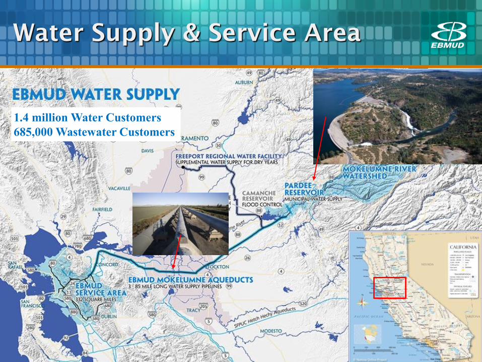
1.4 million Water Customers
685,000 Wastewater Customers
4
Water Supply & Service Area
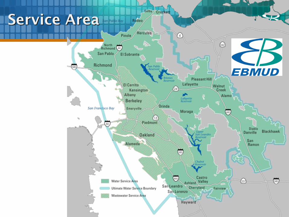
Service Area
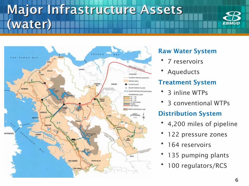
Major Infrastructure Assets
(water)
Raw Water System
• 7 reservoirs
• Aqueducts
Treatment System
• 3 inline WTPs
• 3 conventional WTPs
Distribution System
• 4,200 miles of pipeline
• 122 pressure zones
• 164 reservoirs
• 135 pumping plants
• 100 regulators/RCS
6
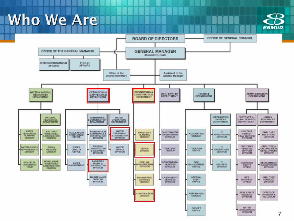
Who We Are
7
Who We Are
8
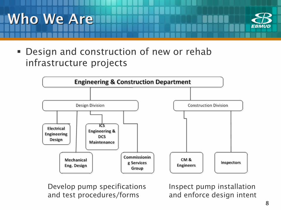
Design and construction of new or rehab
infrastructure projects
Develop pump specifications
and test procedures/forms
Inspect pump installation
and enforce design intent
9
Developed holistic field testing in early 2000s
Functional Test: all equipment and devices
Performance Test: selected equipment
Control Systems Functional Test: EBMUD staff only
Startup Test: All systems operated by EBMUD, contractor on
standby
Witness approach (functional & performance tests):
Contractor run, District witnessed to avoid any
disputed results
Design Engineers conducted the testing
Design Division

Provide technical expertise and leadership for all
commissioning related work to improve overall
safety, quality and reliability upon handover to the
client (O&M)
Enhance overall coordination and communication
between Design, O&M and Construction
Promote continuous design improvements by sharing
lessons learned
10
Dedicated Commissioning Services Group (CSG)
Created in 2017
Commissioning Services Group
11
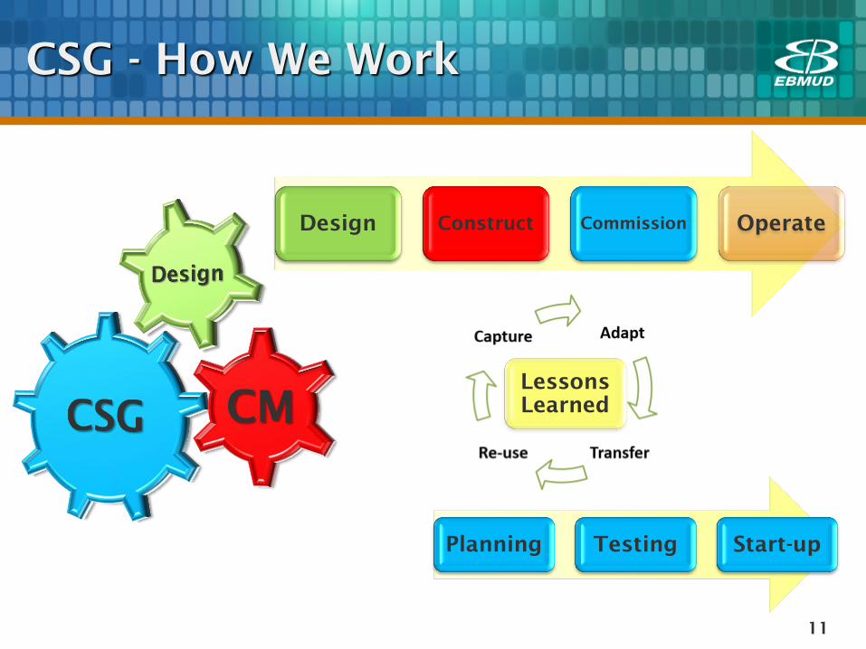
CSG - How We Work
Design Construct Commission Operate
Planning Testing Start-up
Lessons
Learned
12
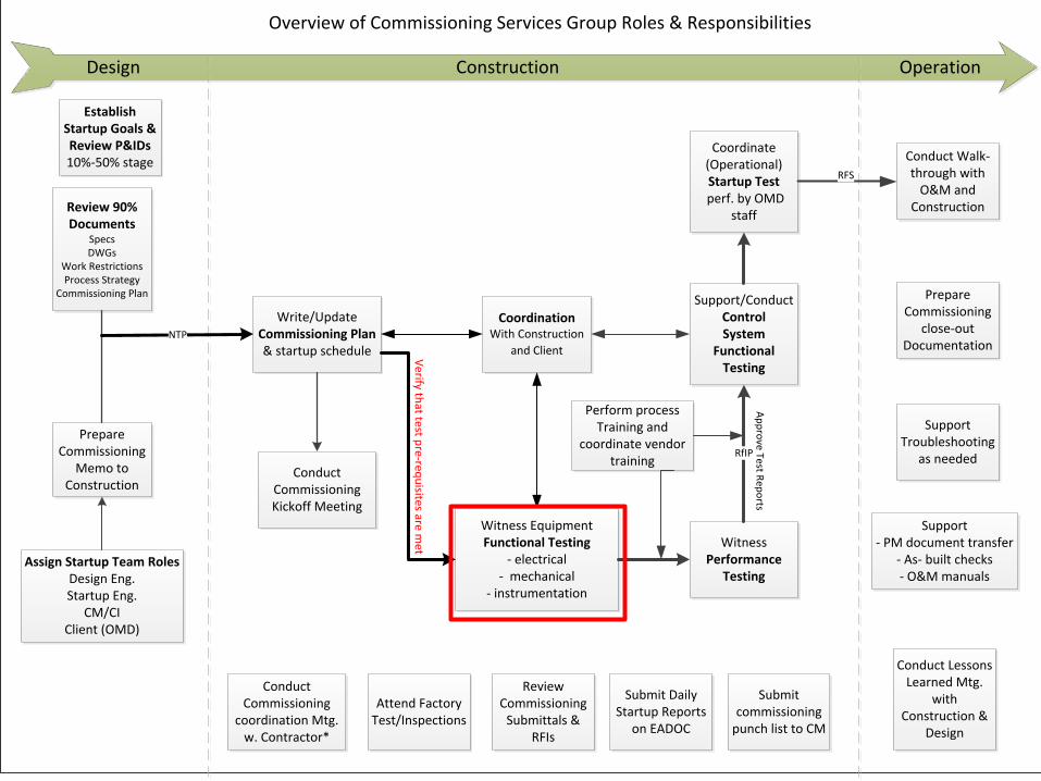
Commissioning Flow and
Terms
Design Construction Operation
Assign Startup Team RolesDesign Eng.Startup Eng.
CM/CIClient (OMD)
Overview of Commissioning Services Group Roles & Responsibilities
Review 90% Documents
SpecsDWGs
Work RestrictionsProcess Strategy
Commissioning Plan
Conduct Commissioning Kickoff Meeting
Witness Equipment Functional Testing
- electrical- mechanical
- instrumentation
Review Commissioning
Submittals & RFIs
Attend Factory Test/Inspections
Write/Update Commissioning Plan& startup schedule
Perform process Training and
coordinate vendor training
Establish Startup Goals & Review P&IDs10%-50% stage
Support- PM document transfer
- As- built checks- O&M manuals
Conduct Walk-through with
O&M and Construction
Support Troubleshooting
as needed
Witness Performance
Testing
Support/Conduct ControlSystem
Functional Testing
RfIP
Coordinate (Operational) Startup Test
perf. by OMD staff
CoordinationWith Construction
and Client
RFS
Conduct Commissioning
coordination Mtg. w. Contractor*
Submit Daily Startup Reports
on EADOC
Prepare Commissioning
close-out Documentation
Prepare Commissioning
Memo to Construction
Submit commissioning
punch list to CM
Conduct Lessons Learned Mtg.
with Construction &
Design
NTP
Verify th
at test pre-req
uisites are m
et
Ap
pro
ve Test Rep
orts
13
Chemical Feed Pump System
Vertical Turbine System
Electrical
Mechanical
Commissioning Case Studies
14
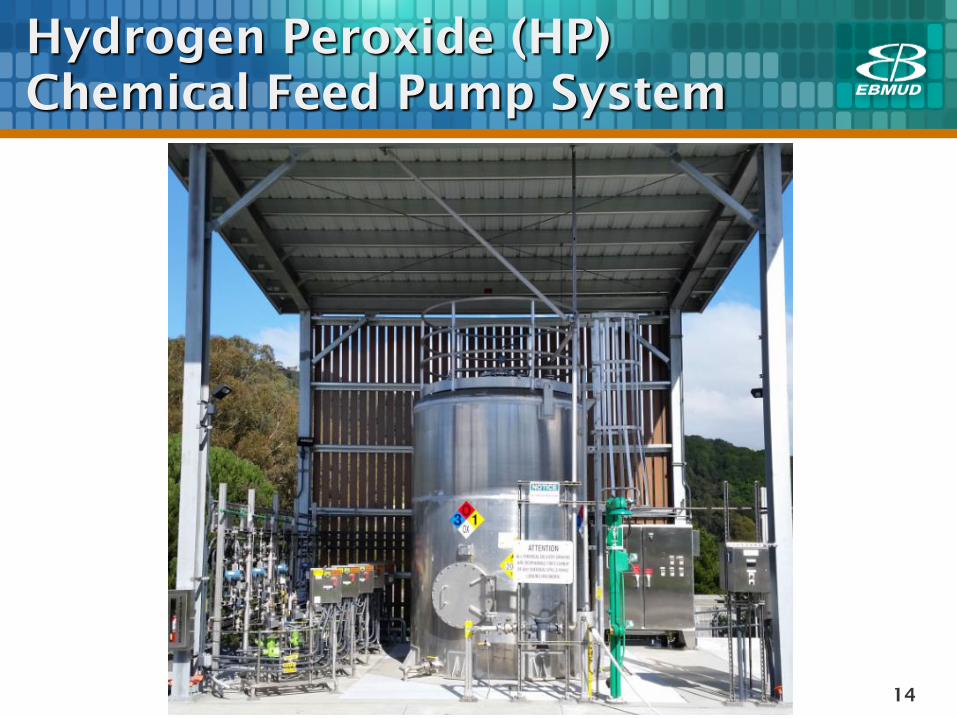
Hydrogen Peroxide (HP)
Chemical Feed Pump System
15
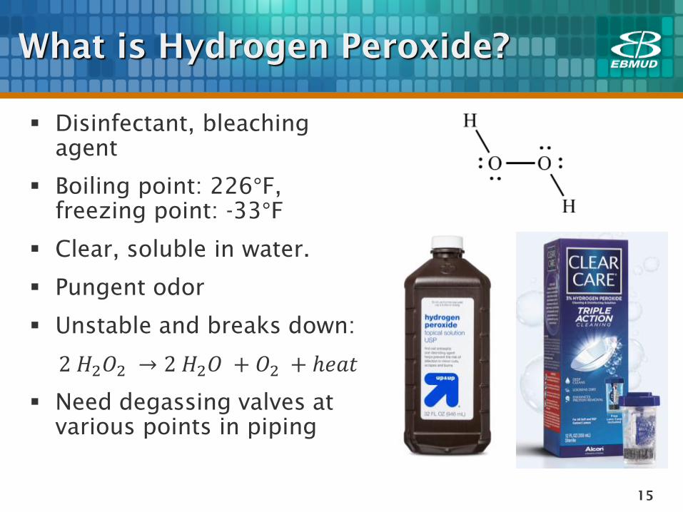
What is Hydrogen Peroxide?
Disinfectant, bleaching
agent
Boiling point: 226°F,
freezing point: -33°F
Clear, soluble in water.
Pungent odor
Unstable and breaks down:
2 𝐻2𝑂2 → 2 𝐻2𝑂 + 𝑂2 + ℎ𝑒𝑎𝑡
Need degassing valves at
various points in piping
16
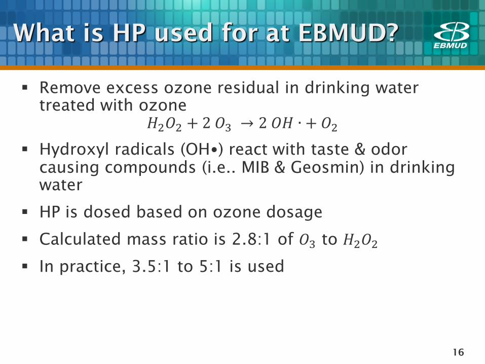
What is HP used for at EBMUD?
Remove excess ozone residual in drinking water
treated with ozone
𝐻2𝑂2 + 2 𝑂3 → 2 𝑂𝐻 ∙ + 𝑂2
Hydroxyl radicals (OH•) react with taste & odor
causing compounds (i.e.. MIB & Geosmin) in drinking
water
HP is dosed based on ozone dosage
Calculated mass ratio is 2.8:1 of 𝑂3 to 𝐻2𝑂2
In practice, 3.5:1 to 5:1 is used
17
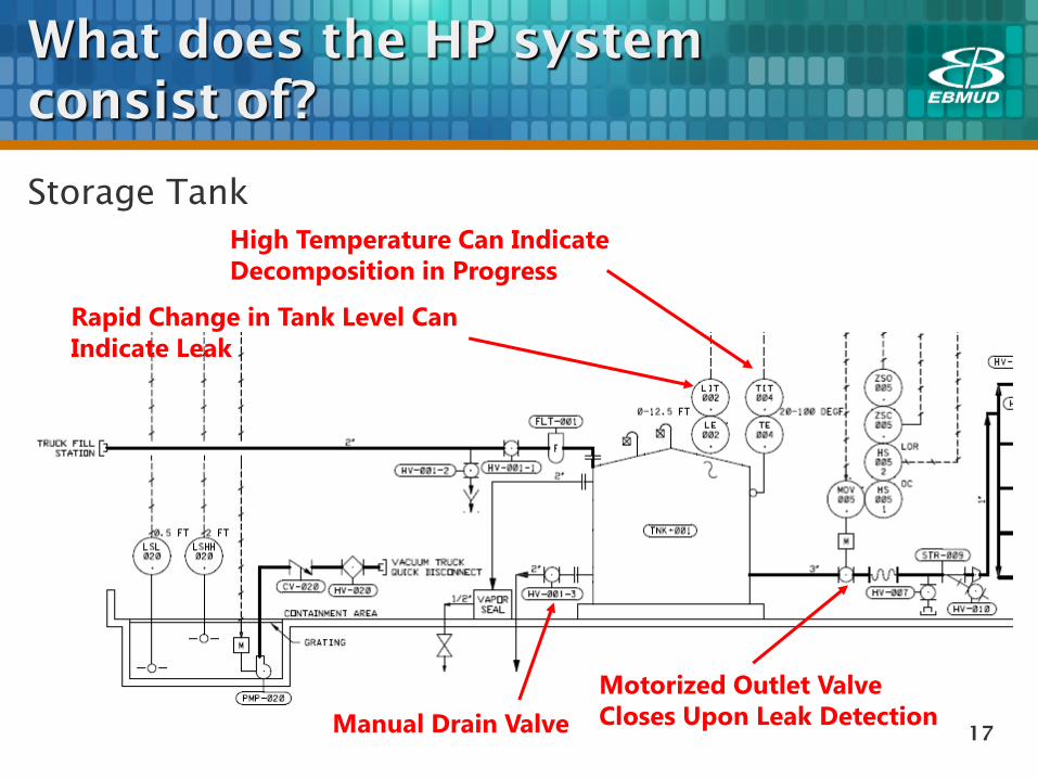
What does the HP system
consist of?
High Temperature Can Indicate
Decomposition in Progress
Rapid Change in Tank Level Can
Indicate Leak
Storage Tank
Motorized Outlet Valve
Closes Upon Leak Detection Manual Drain Valve
18
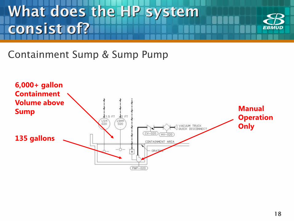
What does the HP system
consist of?
Manual
Operation
Only
135 gallons
6,000+ gallon
Containment
Volume above
Sump
Containment Sump & Sump Pump
19
What does the HP system
consist of?
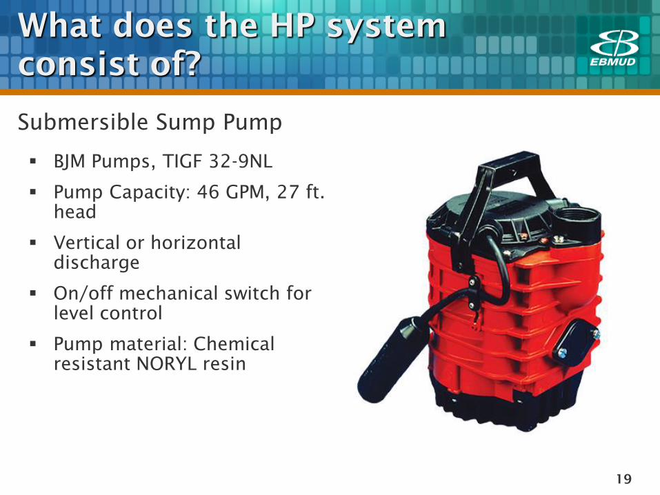
Submersible Sump Pump
BJM Pumps, TIGF 32-9NL
Pump Capacity: 46 GPM, 27 ft.
head
Vertical or horizontal
discharge
On/off mechanical switch for
level control
Pump material: Chemical
resistant NORYL resin
20
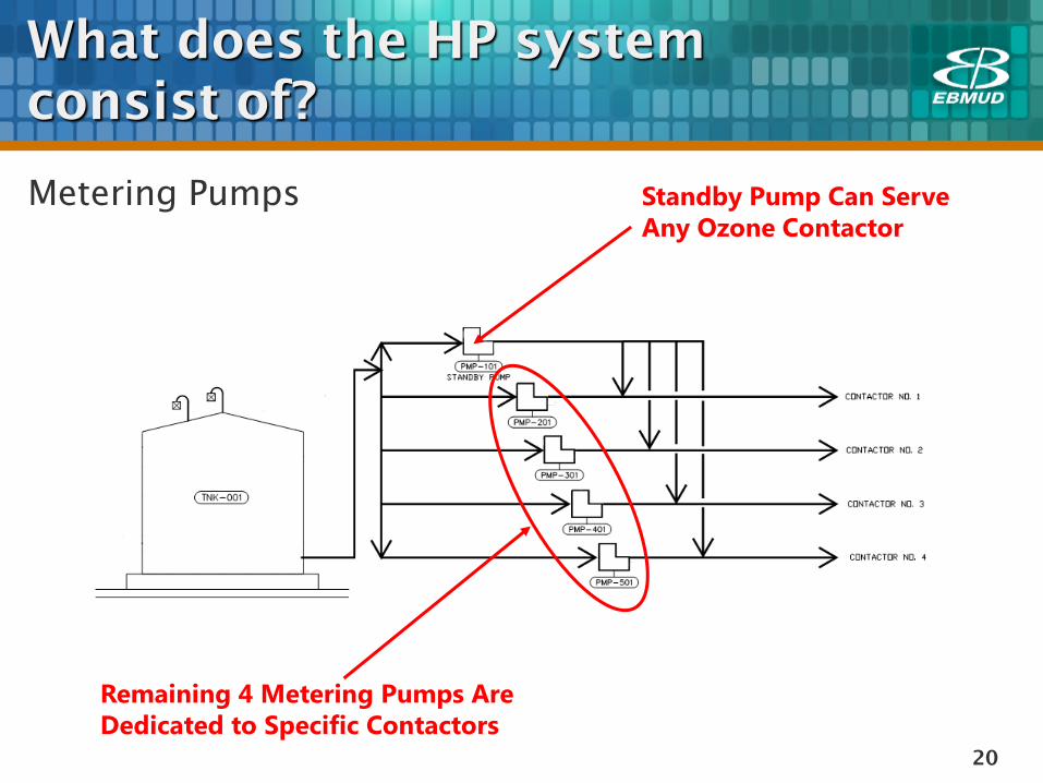
Standby Pump Can Serve
Any Ozone Contactor
Remaining 4 Metering Pumps Are
Dedicated to Specific Contactors
Metering Pumps
What does the HP system
consist of?
21
What does the HP system
consist of?
22
What does the HP system
consist of?
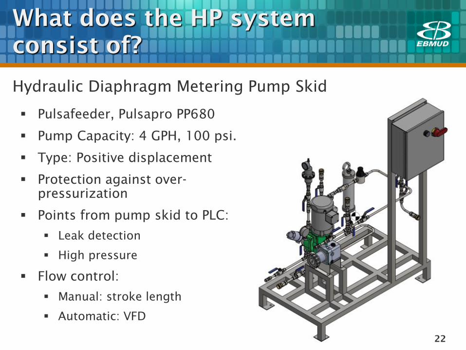
Hydraulic Diaphragm Metering Pump Skid
Pulsafeeder, Pulsapro PP680
Pump Capacity: 4 GPH, 100 psi.
Type: Positive displacement
Protection against over-
pressurization
Points from pump skid to PLC:
Leak detection
High pressure
Flow control:
Manual: stroke length
Automatic: VFD
23
What does the HP system
consist of?
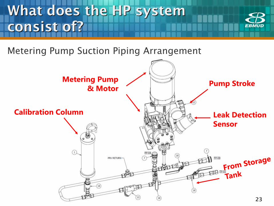
Metering Pump Suction Piping Arrangement
Calibration Column
Metering Pump
& Motor
Leak Detection
Sensor
Pump Stroke
24
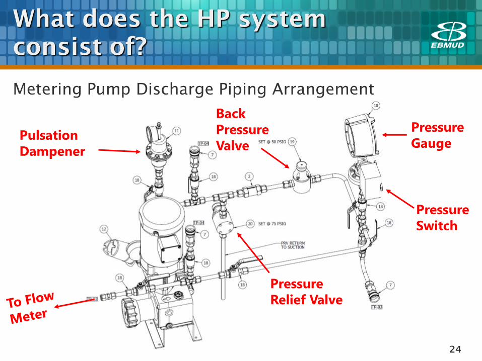
What does the HP system
consist of?
Metering Pump Discharge Piping Arrangement
Pressure
Switch
Pressure
Relief Valve
Pressure
Gauge
Back
Pressure
Valve Pulsation
Dampener
25
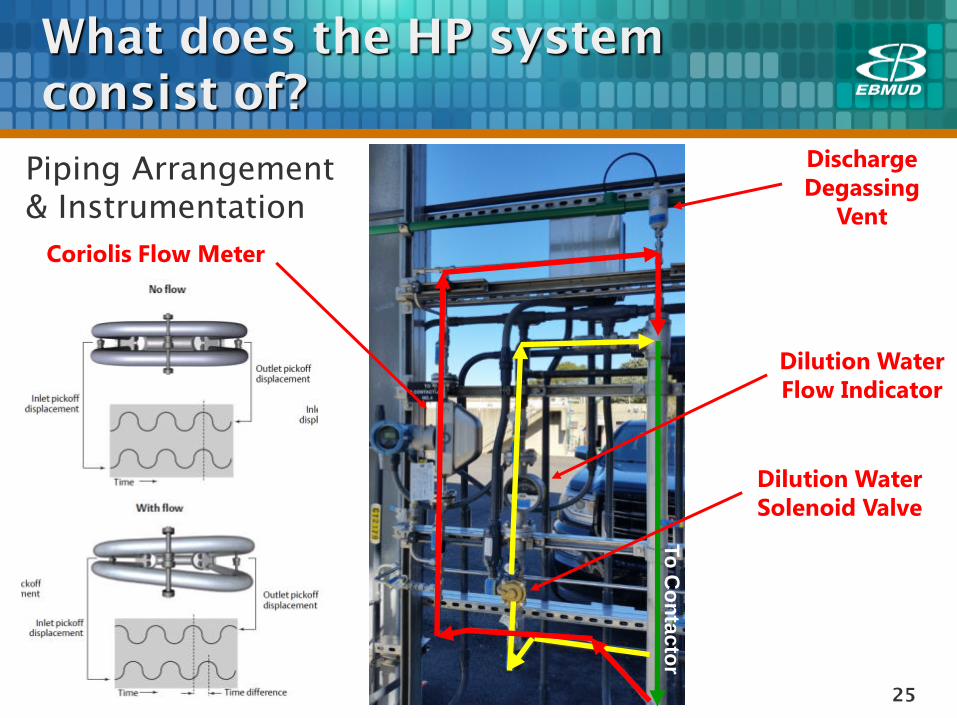
What does the HP system
consist of?
Piping Arrangement
& Instrumentation
Coriolis Flow Meter
Dilution Water
Flow Indicator
Dilution Water
Solenoid Valve
To
Co
nta
cto
r
Discharge
Degassing
Vent
26
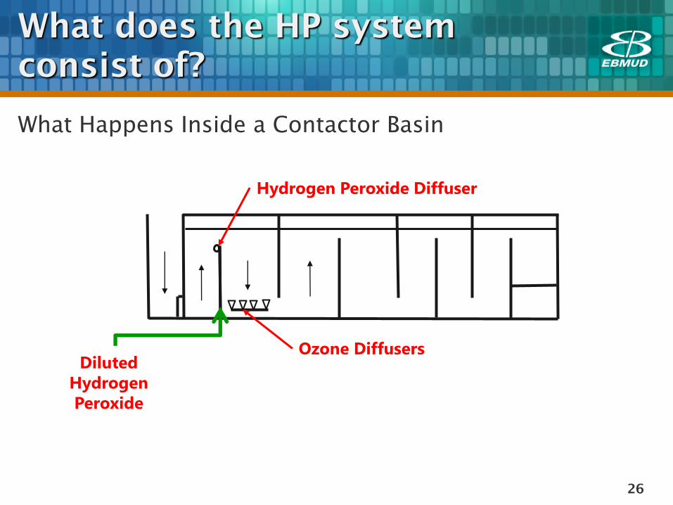
What does the HP system
consist of?
What Happens Inside a Contactor Basin
Ozone Diffusers
Hydrogen Peroxide Diffuser
Diluted
Hydrogen
Peroxide
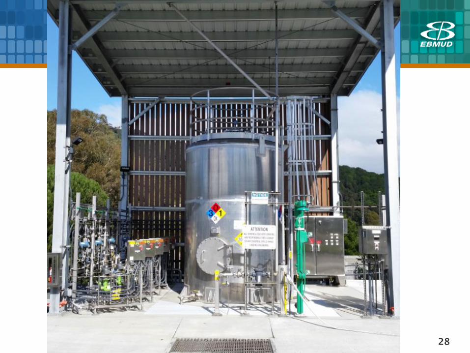
27
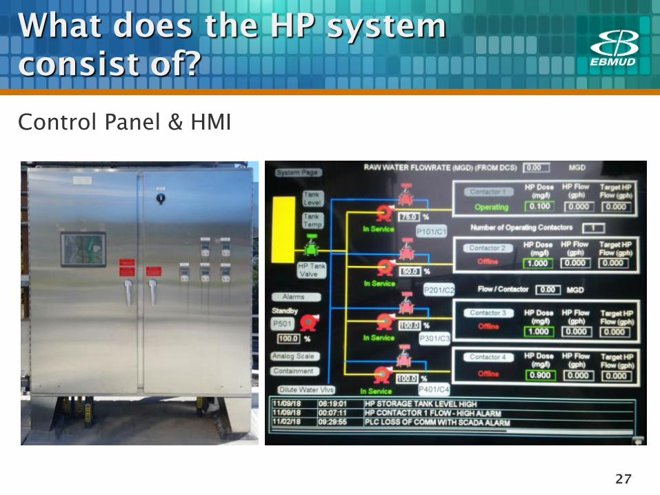
What does the HP system
consist of?
Control Panel & HMI
28
29
How does the HP system work?
Control modes
Dosage mode
Ratio mode
In both modes, flow meter provides feedback signal to
control metering pump speed
Key interlocks
Pump: various alarms
Tank: leak detection alarm
Pump operation interlocked with contactor status
Dilution water valve operation interlocked with metering
pump and contactor status.
30
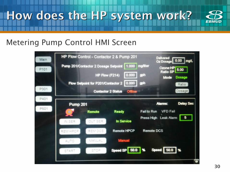
How does the HP system work?
Metering Pump Control HMI Screen
31
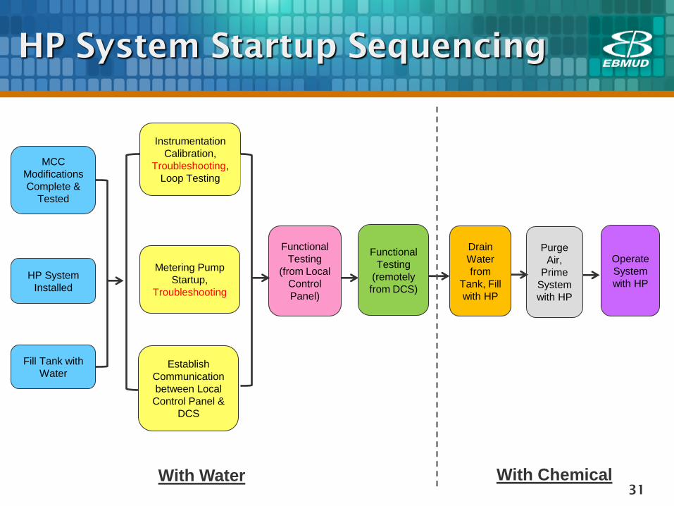
HP System Startup Sequencing
HP System
Installed
MCC
Modifications
Complete &
Tested
Metering Pump
Startup,
Troubleshooting
Instrumentation
Calibration,
Troubleshooting,
Loop Testing
Establish
Communication
between Local
Control Panel &
DCS
Functional
Testing
(from Local
Control
Panel)
Functional
Testing
(remotely
from DCS)
Fill Tank with
Water
Drain
Water
from
Tank, Fill
with HP
Purge
Air,
Prime
System
with HP
Operate
System
with HP
With Water With Chemical
32
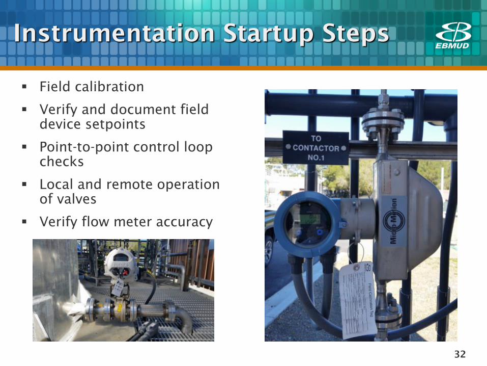
Instrumentation Startup Steps
Field calibration
Verify and document field
device setpoints
Point-to-point control loop
checks
Local and remote operation
of valves
Verify flow meter accuracy
33
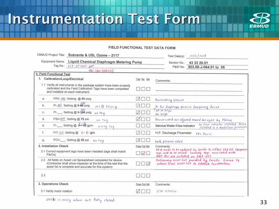
Instrumentation Test Form
34
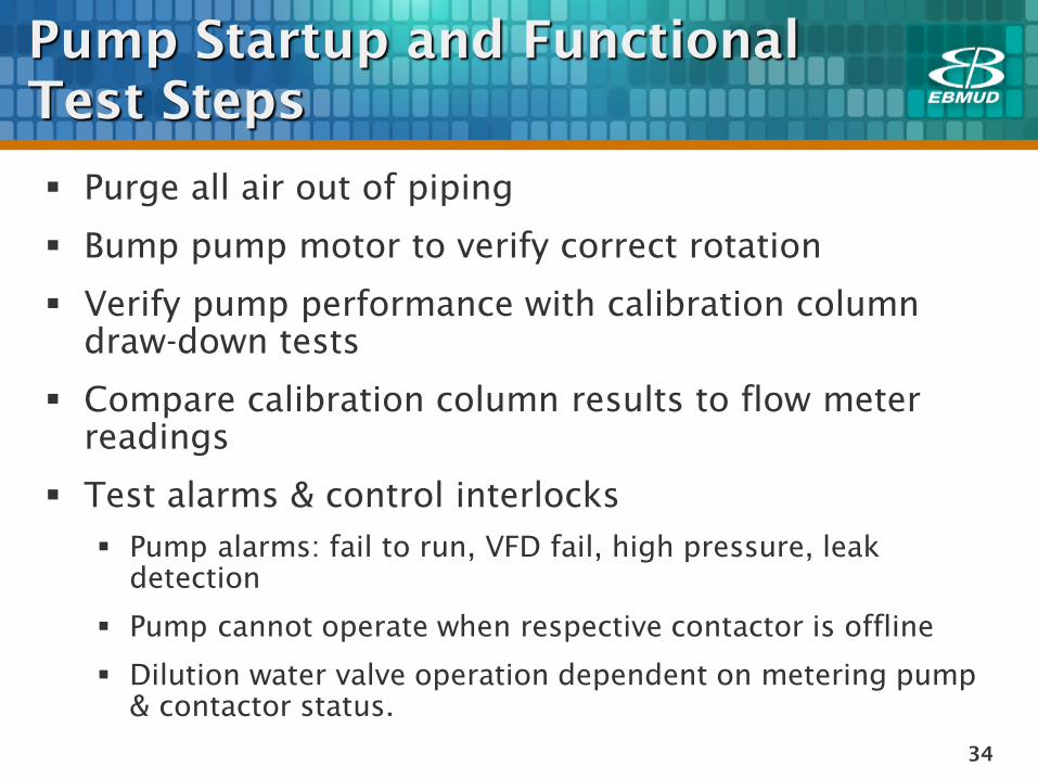
Pump Startup and Functional
Test Steps
Purge all air out of piping
Bump pump motor to verify correct rotation
Verify pump performance with calibration column
draw-down tests
Compare calibration column results to flow meter
readings
Test alarms & control interlocks
Pump alarms: fail to run, VFD fail, high pressure, leak
detection
Pump cannot operate when respective contactor is offline
Dilution water valve operation dependent on metering pump
& contactor status.
35
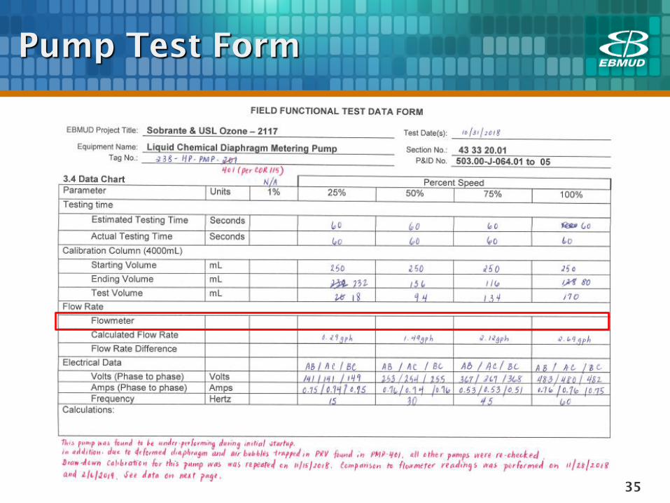
Pump Test Form
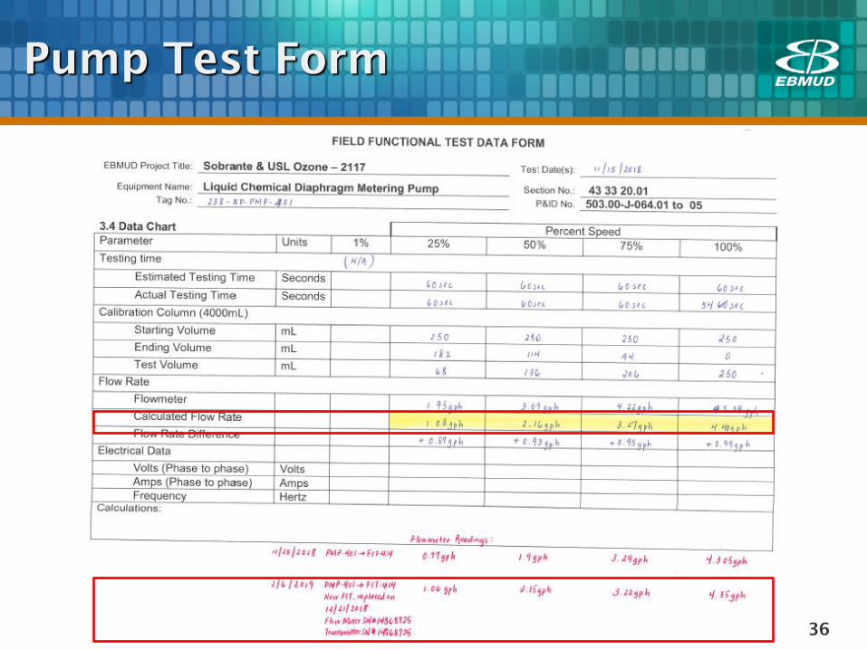
36
Pump Test Form
37
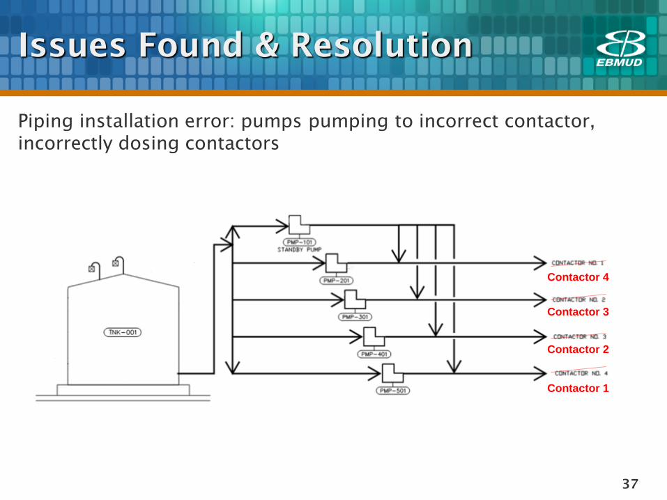
Issues Found & Resolution
Piping installation error: pumps pumping to incorrect contactor,
incorrectly dosing contactors
Contactor 4
Contactor 3
Contactor 2
Contactor 1
38
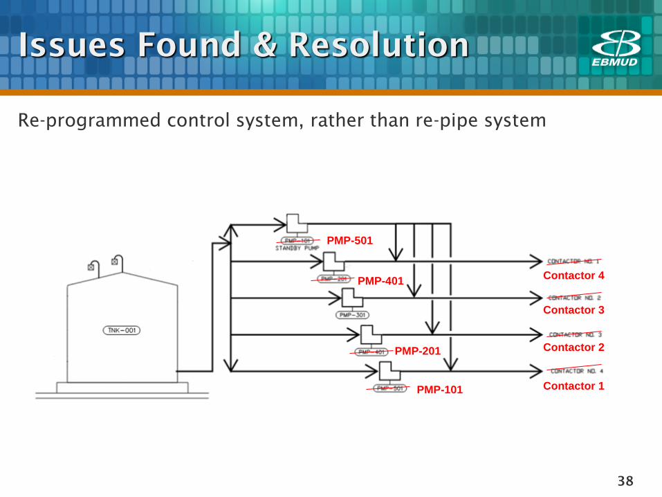
Issues Found & Resolution
Re-programmed control system, rather than re-pipe system
Contactor 4
Contactor 3
Contactor 2
Contactor 1
PMP-501
PMP-401
PMP-201
PMP-101
39
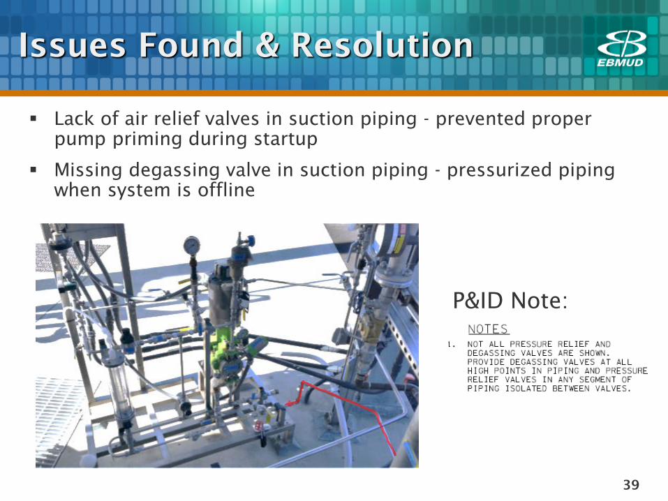
Issues Found & Resolution
P&ID Note:
Lack of air relief valves in suction piping - prevented proper
pump priming during startup
Missing degassing valve in suction piping - pressurized piping
when system is offline
40
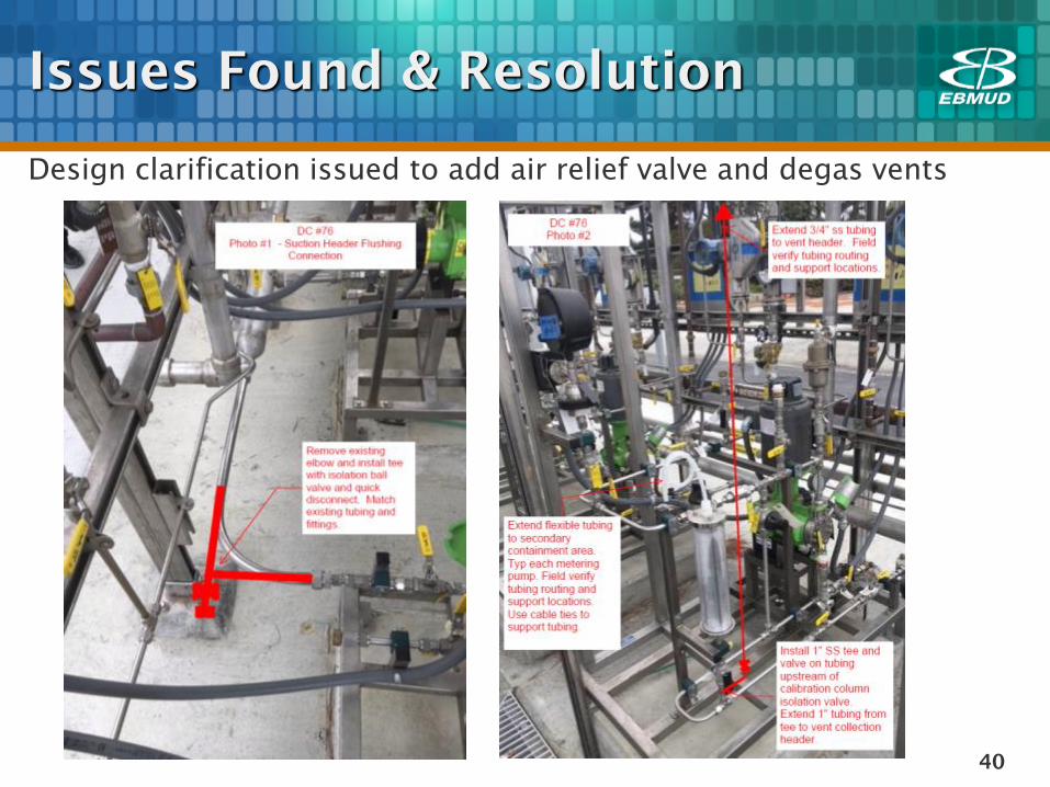
Issues Found & Resolution
Design clarification issued to add air relief valve and degas vents
41
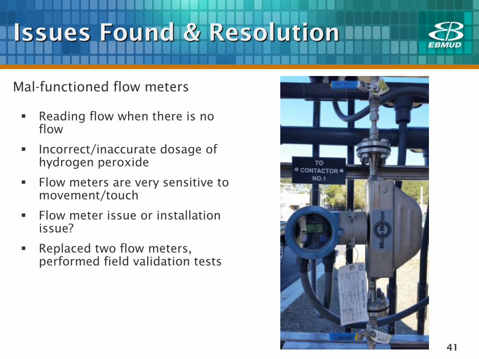
Issues Found & Resolution
Mal-functioned flow meters
Reading flow when there is no
flow
Incorrect/inaccurate dosage of
hydrogen peroxide
Flow meters are very sensitive to
movement/touch
Flow meter issue or installation
issue?
Replaced two flow meters,
performed field validation tests
42
Issues Found & Resolution
Control system programming corrections
Erroneously latching alarms
Leak detection alarm
Incorrect mapping of points between contactors
Metering pump PID control loop tuning

43
Lessons Learned from HP
System Commissioning
Seek input from O&M staff during Design Phase
Drawings to clearly show all pressure relief and degassing valves
in piping
Closely inspect of piping installation against conformance
drawings
Ensure Contractor is flushing pipes prior to all testing (chemical
and water service), with substantial tracking and recording.
Request factory rep troubleshoot at first occurrence of flow
meter malfunction
Perform control system functional testing with PLC programmer
Coordination, coordination, coordination!
44
QUESTIONS
Chemical Feed System
Commissioning
45
Chemical Feed Pump System
Vertical Turbine Pumps
Electrical
Mechanical
Commissioning Case Studies

46
Design Review
Submittal Review
Factory Tests
Installation
Equipment
Integration
Field Startup and
Commissioning
Final Reports and
As-Built Drawings
Electrical System
Commissioning
47
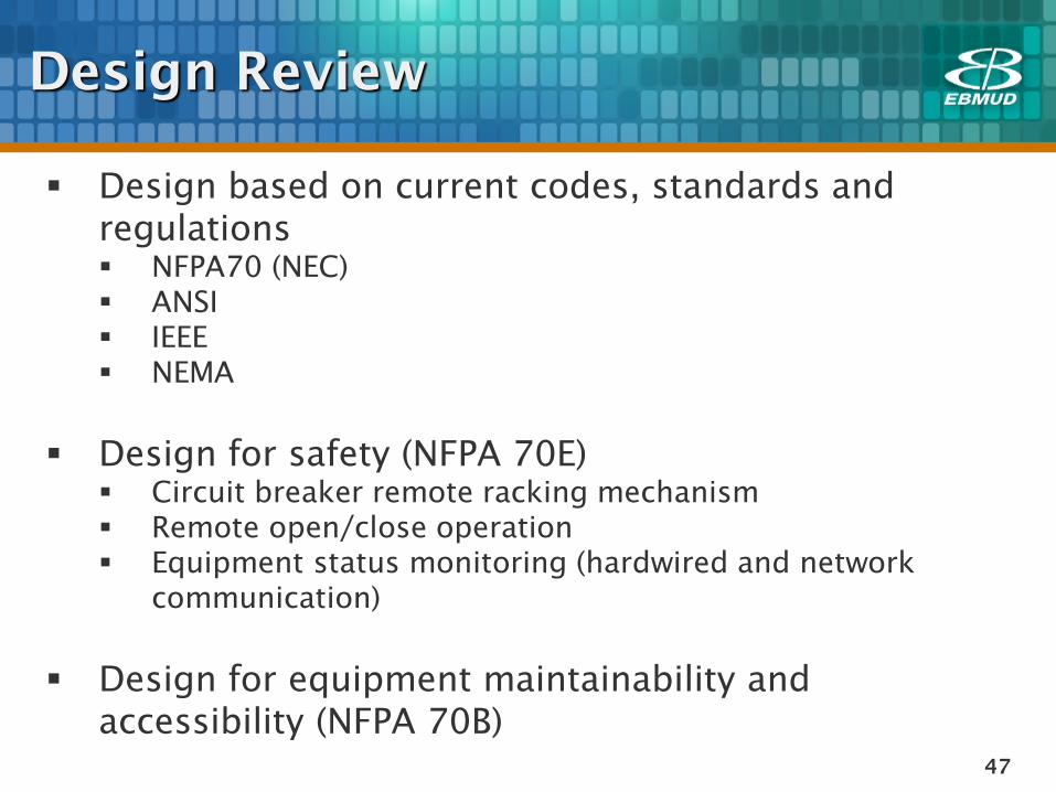
Design Review
Design based on current codes, standards and
regulations
NFPA70 (NEC)
ANSI
IEEE
NEMA
Design for safety (NFPA 70E)
Circuit breaker remote racking mechanism
Remote open/close operation
Equipment status monitoring (hardwired and network
communication)
Design for equipment maintainability and
accessibility (NFPA 70B)
48
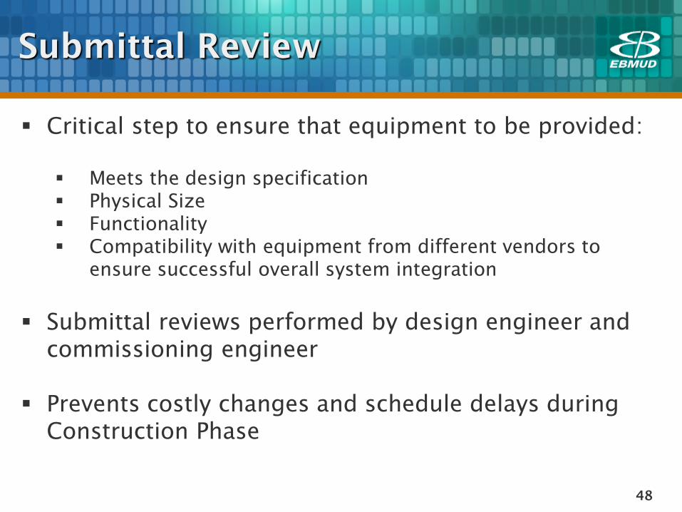
Submittal Review
Critical step to ensure that equipment to be provided:
Meets the design specification
Physical Size
Functionality
Compatibility with equipment from different vendors to
ensure successful overall system integration
Submittal reviews performed by design engineer and
commissioning engineer
Prevents costly changes and schedule delays during
Construction Phase
49
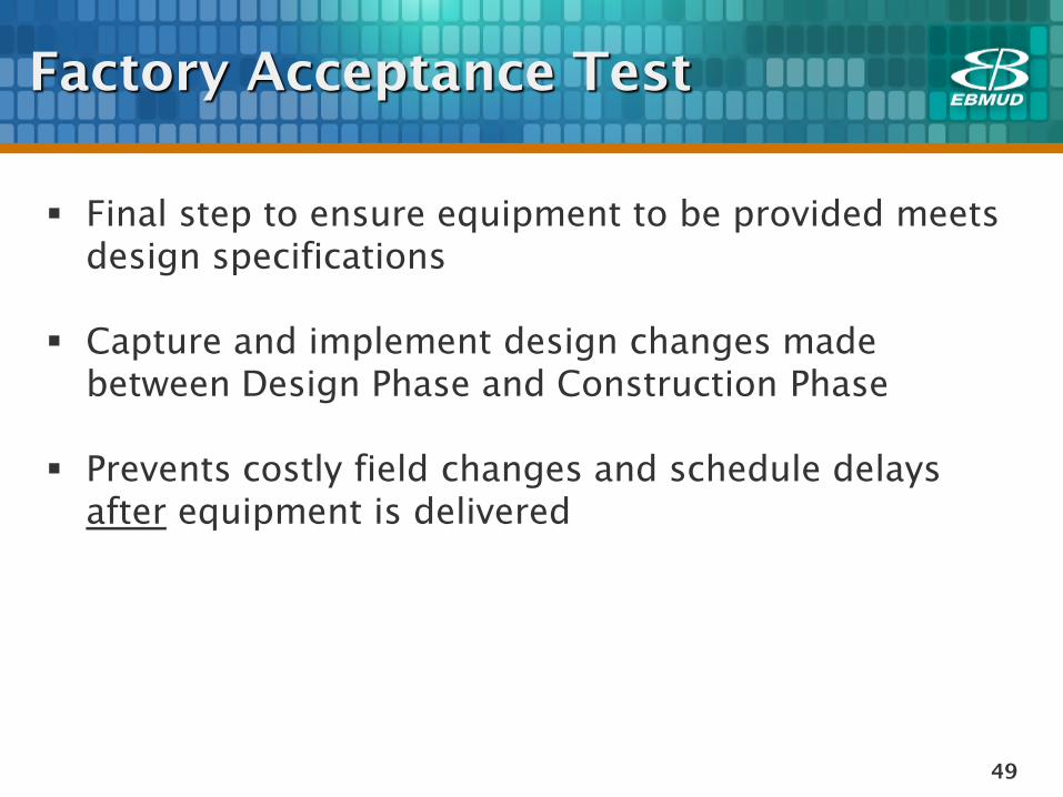
Factory Acceptance Test
Final step to ensure equipment to be provided meets
design specifications
Capture and implement design changes made
between Design Phase and Construction Phase
Prevents costly field changes and schedule delays
after equipment is delivered
50
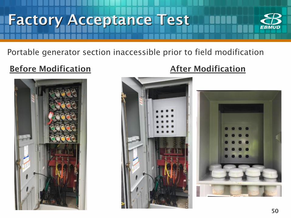
Factory Acceptance Test
Portable generator section inaccessible prior to field modification
Before Modification After Modification
51
Equipment Installation
Visual inspection of equipment installation
Verify installation meets manufacturers
recommendation and current codes and regulations
Verify equipment clearance/accessibility for
maintenance
52
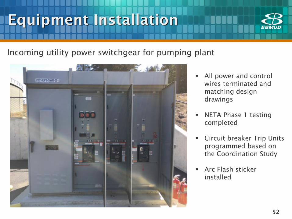
Equipment Installation
Incoming utility power switchgear for pumping plant
All power and control
wires terminated and
matching design
drawings
NETA Phase 1 testing
completed
Circuit breaker Trip Units
programmed based on
the Coordination Study
Arc Flash sticker
installed
53
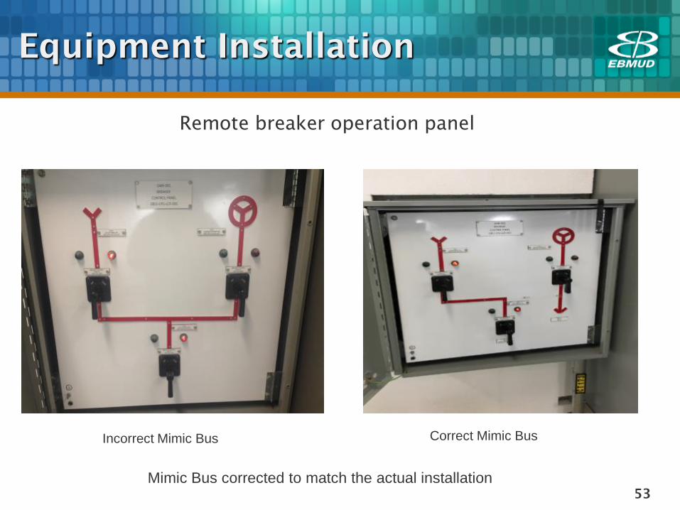
Equipment Installation
Remote breaker operation panel
Mimic Bus corrected to match the actual installation
Incorrect Mimic Bus Correct Mimic Bus
54
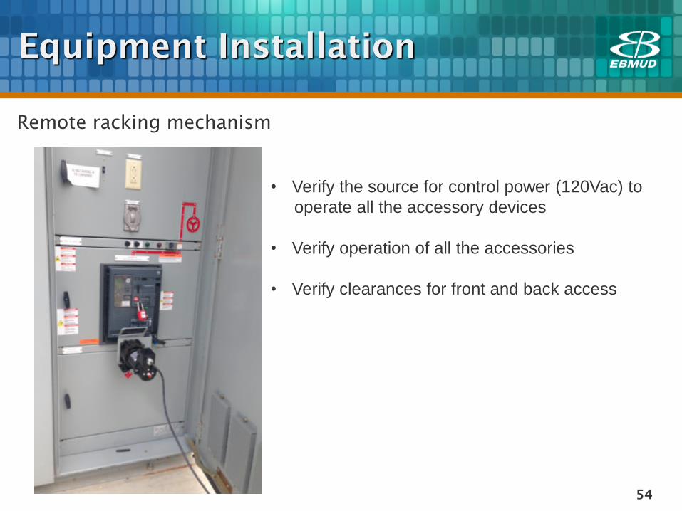
Equipment Installation
Remote racking mechanism
• Verify the source for control power (120Vac) to
operate all the accessory devices
• Verify operation of all the accessories
• Verify clearances for front and back access
55
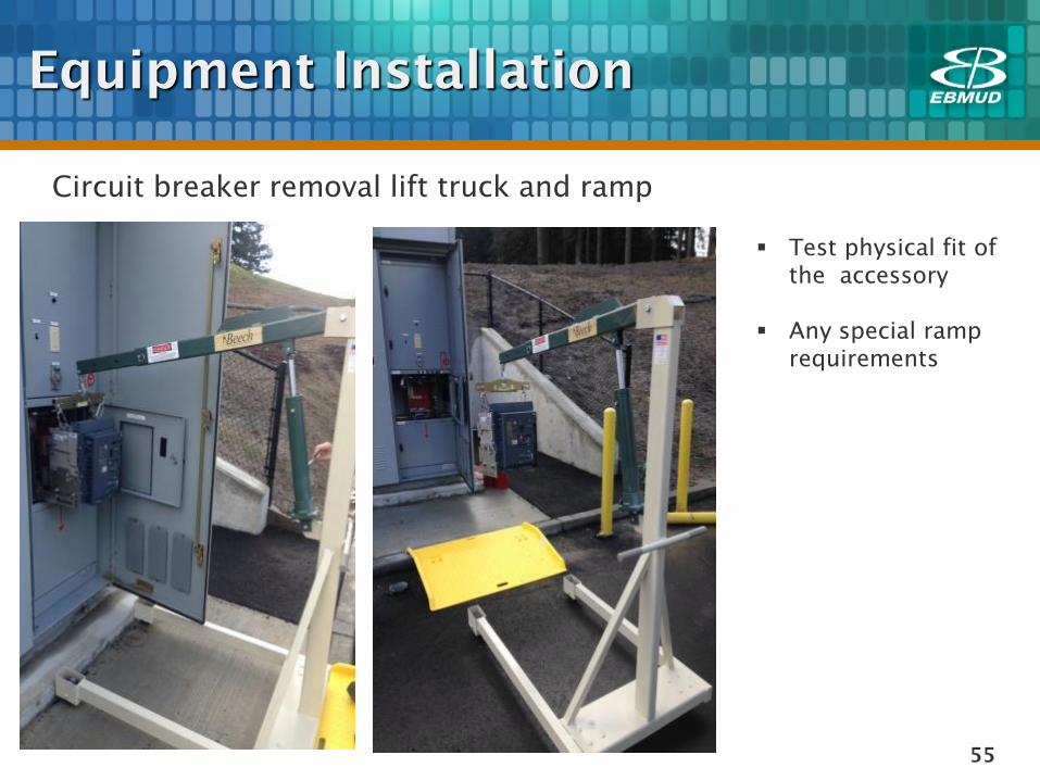
Equipment Installation
Circuit breaker removal lift truck and ramp
Test physical fit of
the accessory
Any special ramp
requirements
56
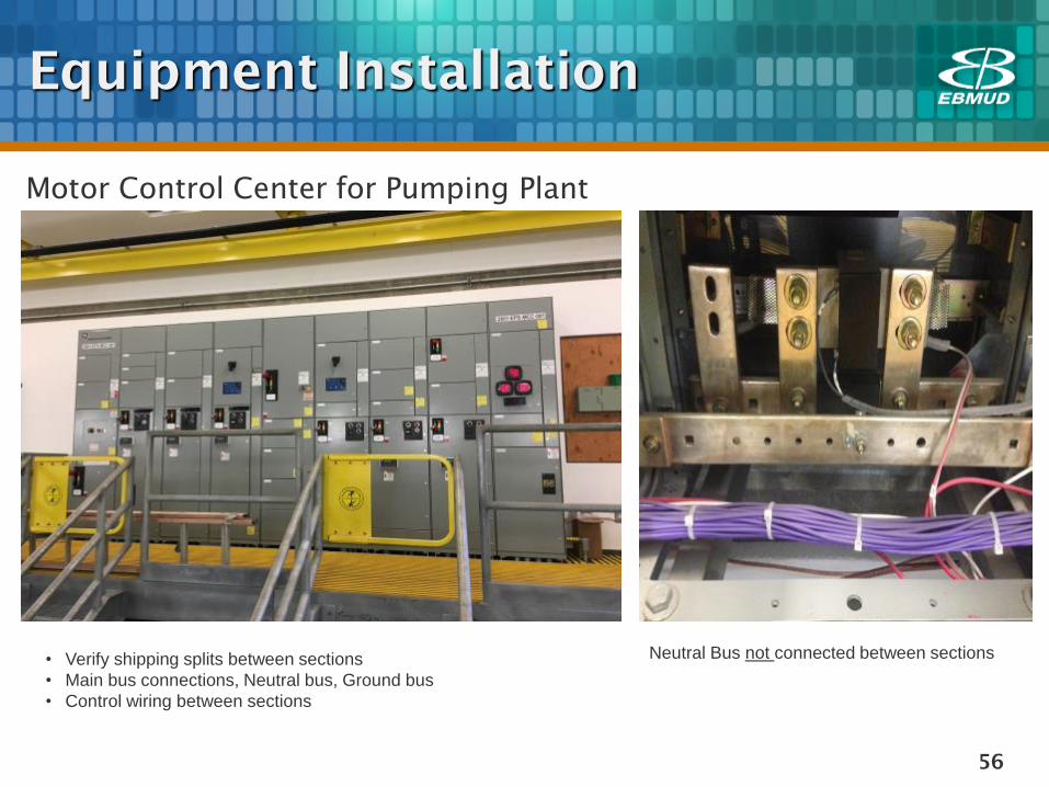
Equipment Installation
Motor Control Center for Pumping Plant
• Verify shipping splits between sections
• Main bus connections, Neutral bus, Ground bus
• Control wiring between sections
Neutral Bus not connected between sections
57
Field Startup and
Commissioning
Final visual inspection & walk-through with O&M and
construction team before energizing the equipment
Energization
Phase rotation checks with Utility and Generator power
Bump motors to check rotation
58
Field Startup and
Commissioning
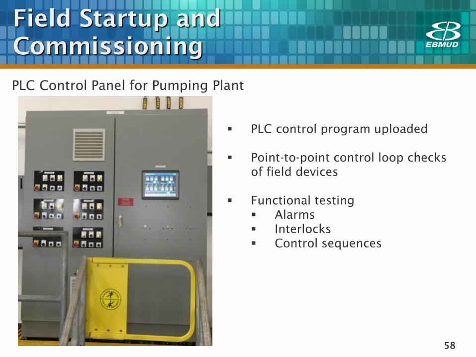
PLC Control Panel for Pumping Plant
PLC control program uploaded
Point-to-point control loop checks
of field devices
Functional testing
Alarms
Interlocks
Control sequences

59
Field Startup and
Commissioning
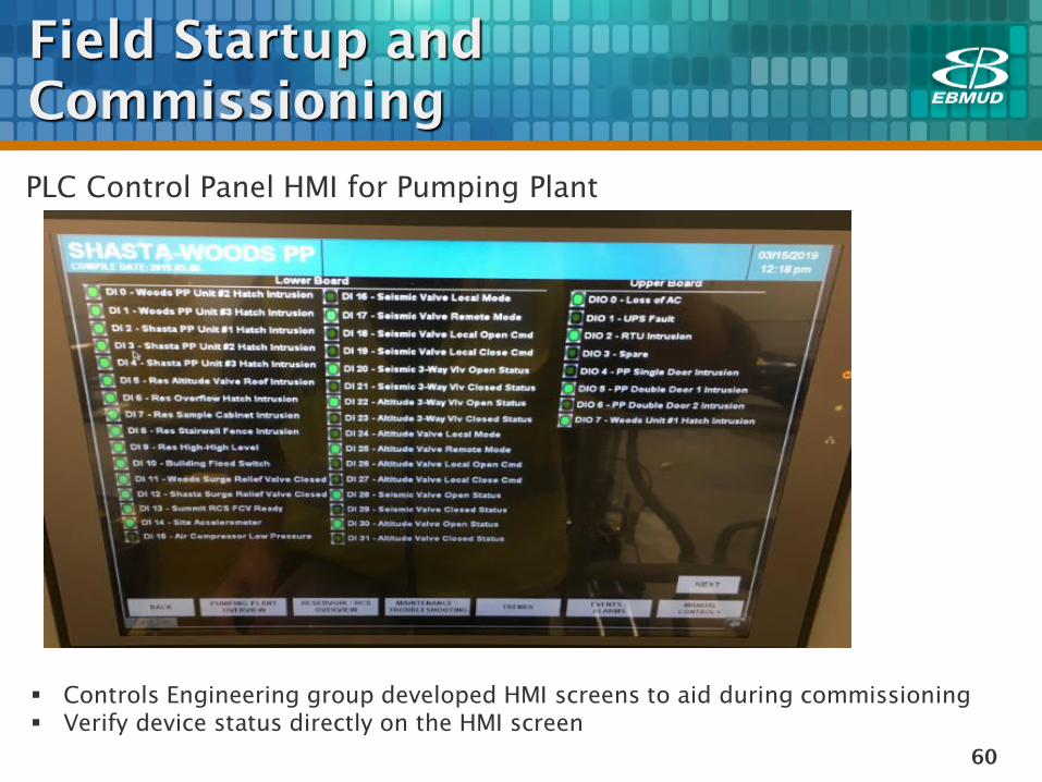
PLC Control Panel HMI for Pumping Plant
Perform testing of all field devices from the end device to the HMI
Ideally initiate the actual condition for status, alarm, fault or analog signal at the
end device
Some failure modes need special setup to verify the operation of the system
60
Field Startup and
Commissioning
PLC Control Panel HMI for Pumping Plant
Controls Engineering group developed HMI screens to aid during commissioning
Verify device status directly on the HMI screen
61
Field Startup and
Commissioning
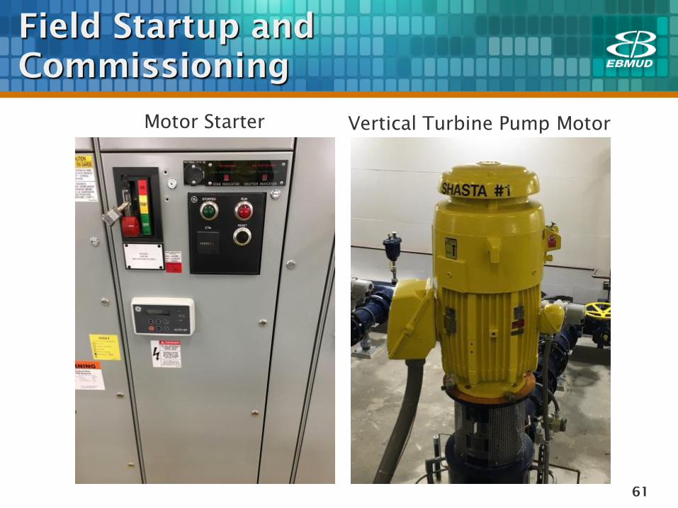
Motor Starter Vertical Turbine Pump Motor
62
Field Startup and
Commissioning
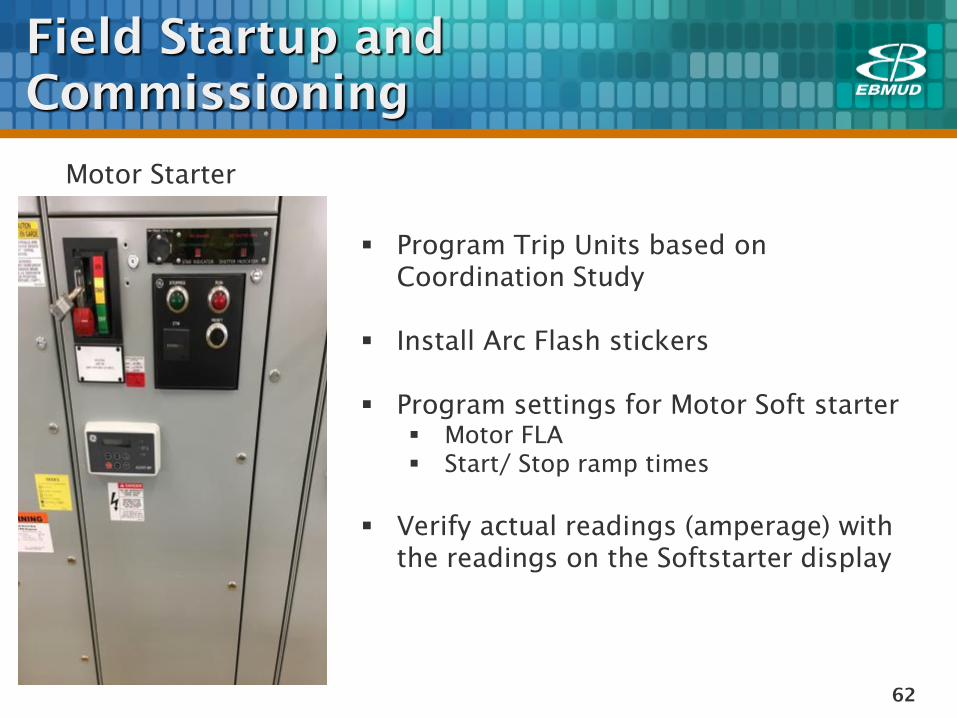
Motor Starter
Program Trip Units based on
Coordination Study
Install Arc Flash stickers
Program settings for Motor Soft starter
Motor FLA
Start/ Stop ramp times
Verify actual readings (amperage) with
the readings on the Softstarter display
63
Field Startup and
Commissioning
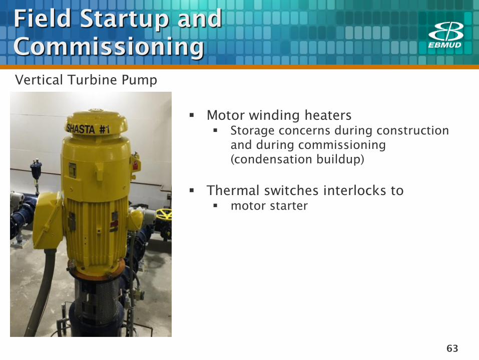
Vertical Turbine Pump
Motor winding heaters
Storage concerns during construction
and during commissioning
(condensation buildup)
Thermal switches interlocks to
motor starter
64
Field Startup and
Commissioning
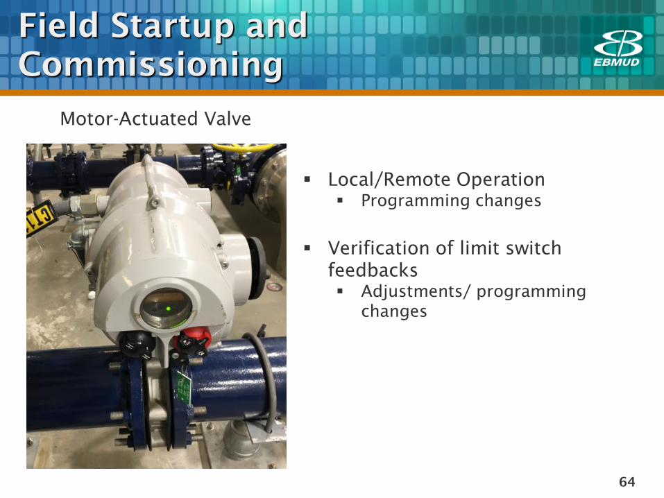
Motor-Actuated Valve
Local/Remote Operation
Programming changes
Verification of limit switch
feedbacks
Adjustments/ programming
changes
65
Field Startup and
Commissioning
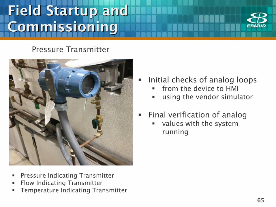
Pressure Transmitter
Initial checks of analog loops
from the device to HMI
using the vendor simulator
Final verification of analog
values with the system
running
Pressure Indicating Transmitter
Flow Indicating Transmitter
Temperature Indicating Transmitter
66
Documentation & Field Changes
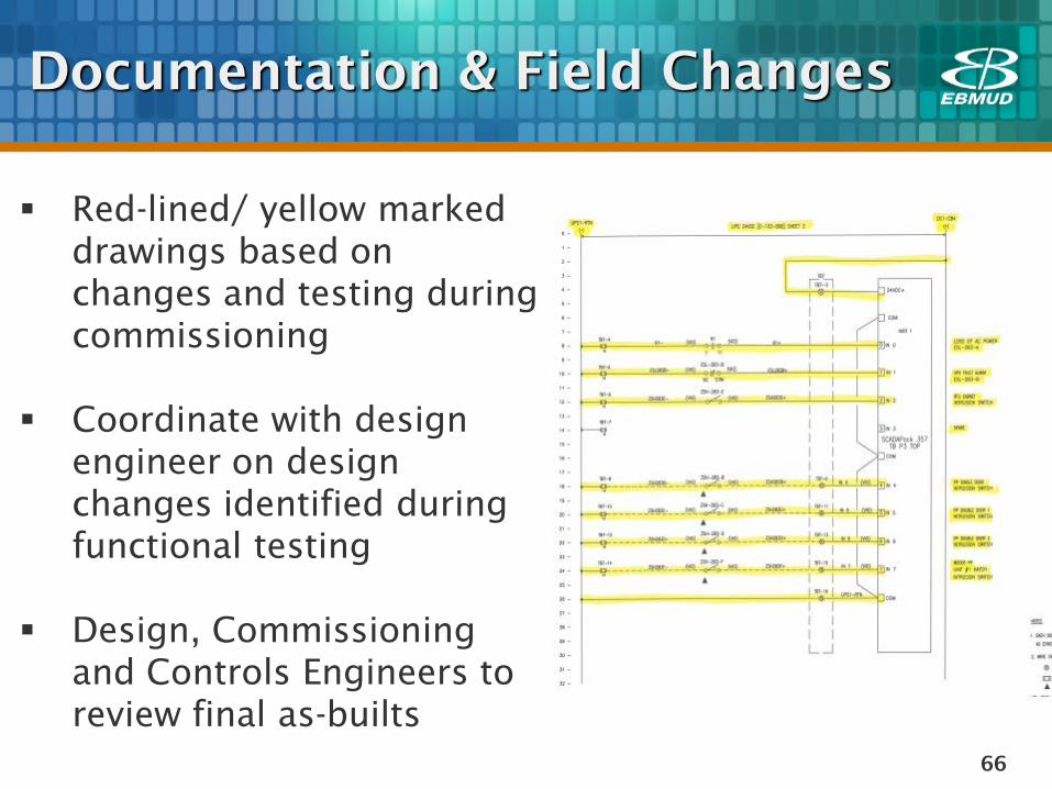
Red-lined/ yellow marked
drawings based on
changes and testing during
commissioning
Coordinate with design
engineer on design
changes identified during
functional testing
Design, Commissioning
and Controls Engineers to
review final as-builts
67
Documentation & Field Changes
Completed test forms for individual devices
Completed test forms for complete system
integration
Final documentation to O&M groups
68
QUESTIONS
Vertical Turbine Pumps –
Electrical Commissioning
69
Chemical Feed Pump System
Vertical Turbine Pumps
Electrical
Mechanical
Commissioning Case Studies
70
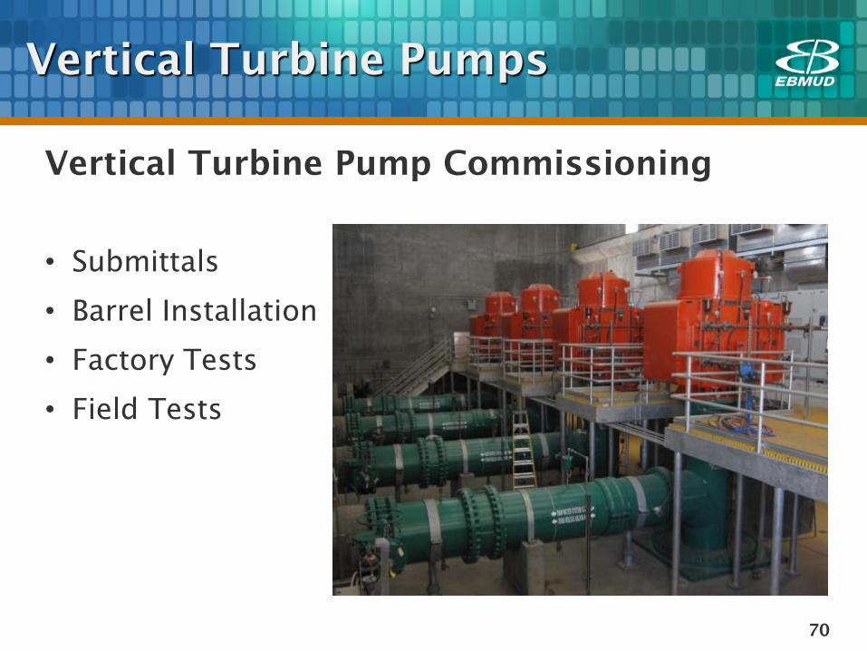
Vertical Turbine Pump Commissioning
• Submittals
• Barrel Installation
• Factory Tests
• Field Tests
Vertical Turbine Pumps
71
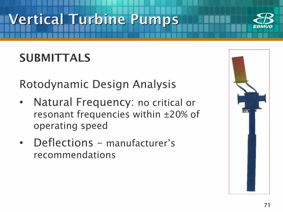
SUBMITTALS
Rotodynamic Design Analysis
• Natural Frequency: no critical or
resonant frequencies within ±20% of
operating speed
• Deflections – manufacturer’s
recommendations
Vertical Turbine Pumps
72
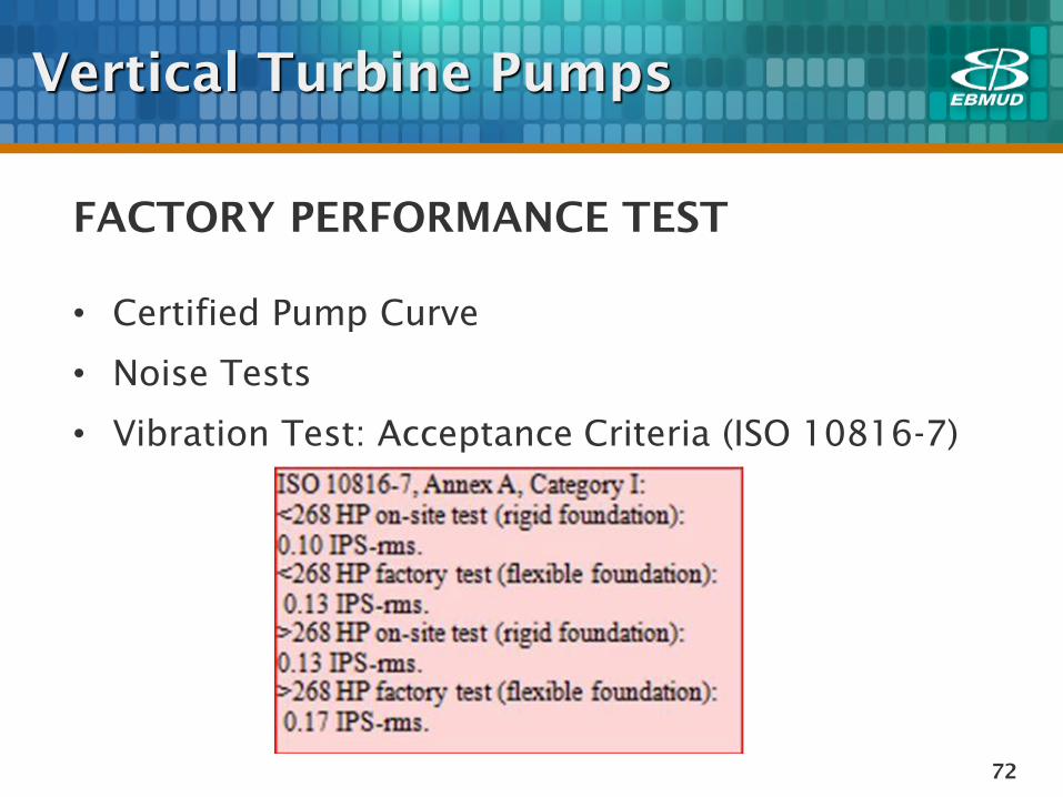
FACTORY PERFORMANCE TEST
• Certified Pump Curve
• Noise Tests
• Vibration Test: Acceptance Criteria (ISO 10816-7)
Vertical Turbine Pumps
73
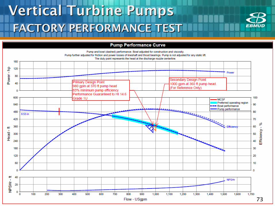
Vertical Turbine Pumps
FACTORY PERFORMANCE TEST
74
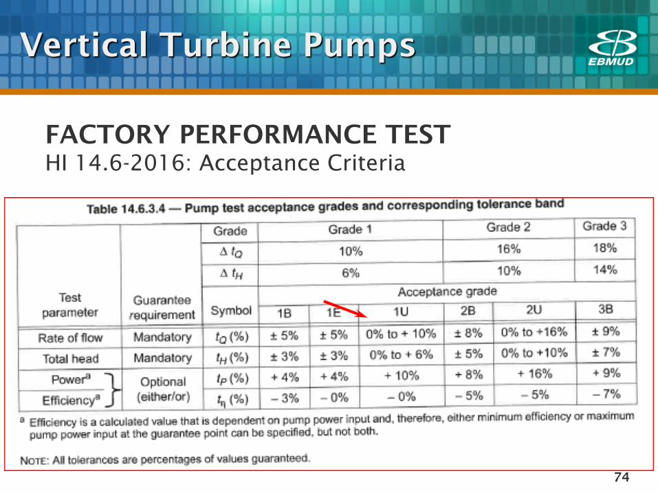
FACTORY PERFORMANCE TEST
HI 14.6-2016: Acceptance Criteria
Vertical Turbine Pumps
75
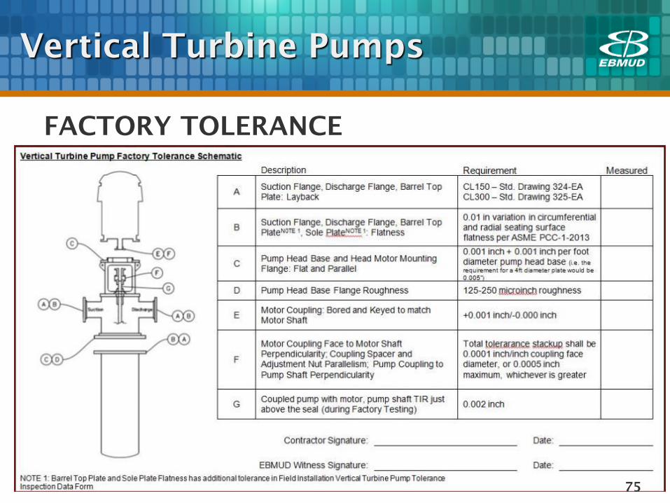
FACTORY TOLERANCE
Vertical Turbine Pumps
76
BARREL PLACEMENT
• True vertical: ±3/64” per foot of barrel
length
• Fill barrel with water prior to placing
concrete to reduce buoyancy
• Block and anchor in place
Vertical Turbine Pumps
77
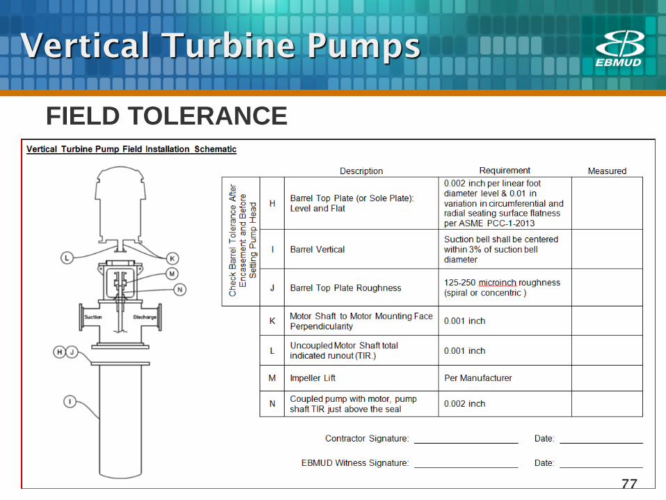
FIELD TOLERANCE
Vertical Turbine Pumps

78
BARREL PLACEMENT
Vertical Turbine Pumps
79
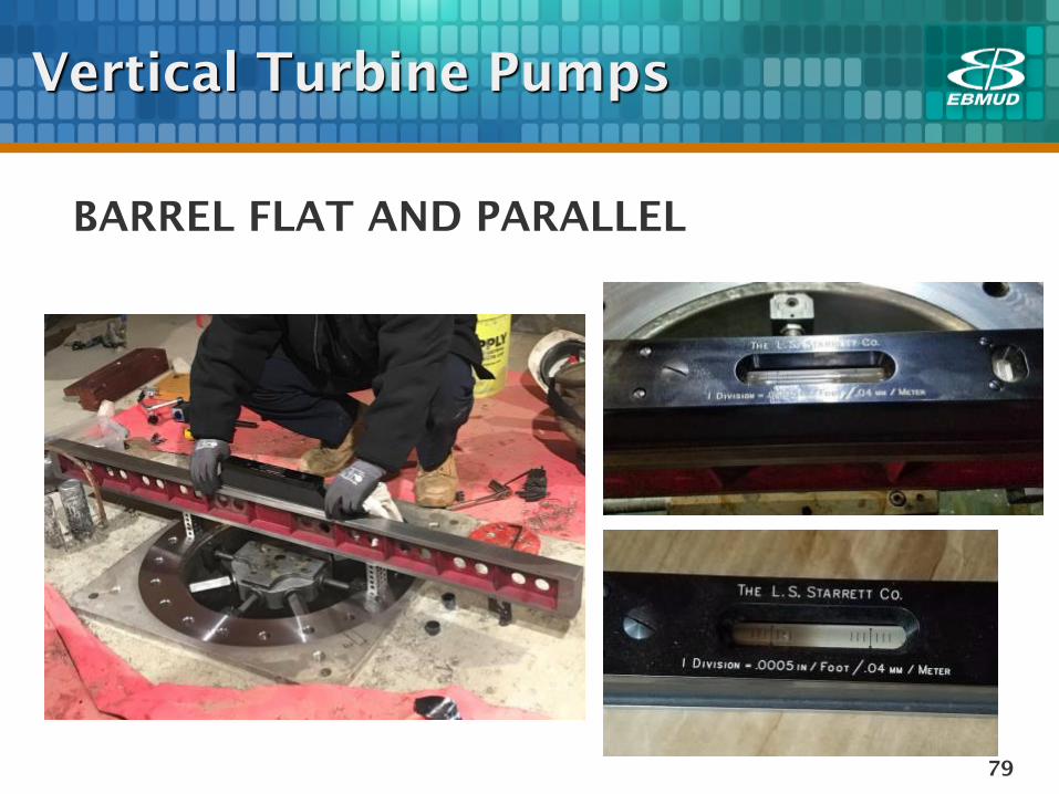
BARREL FLAT AND PARALLEL
Vertical Turbine Pumps
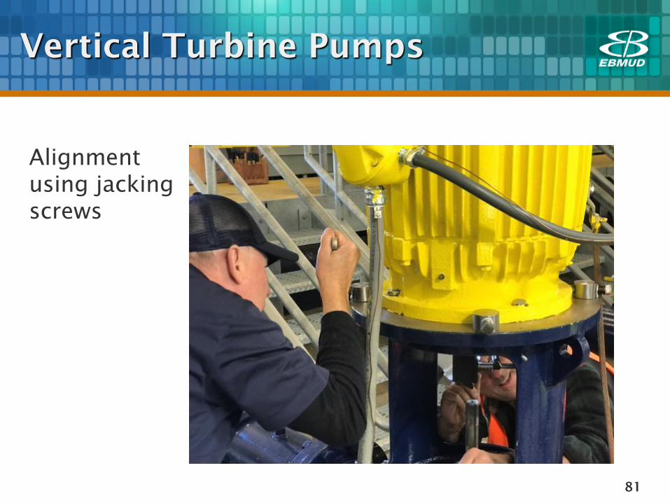
81
Alignment
using jacking
screws
Vertical Turbine Pumps
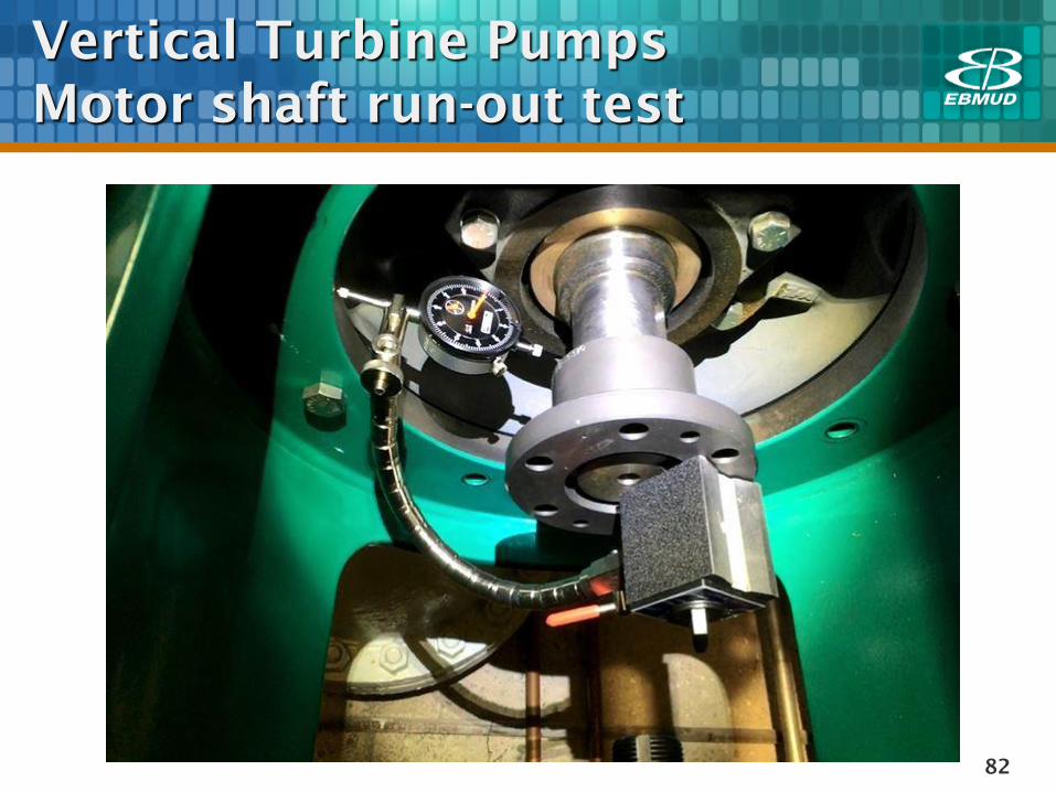
82
Vertical Turbine Pumps
Motor shaft run-out test
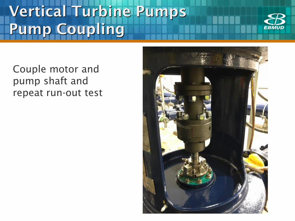
Vertical Turbine Pumps
Pump Coupling
Couple motor and
pump shaft and
repeat run-out test
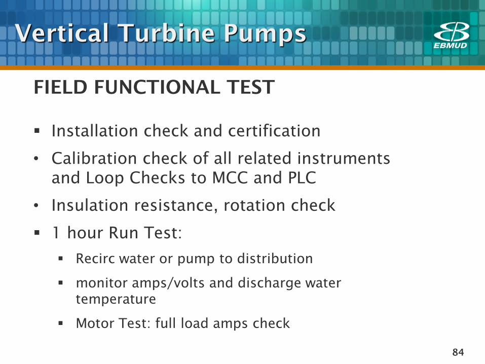
84
FIELD FUNCTIONAL TEST
Installation check and certification
• Calibration check of all related instruments
and Loop Checks to MCC and PLC
• Insulation resistance, rotation check
1 hour Run Test:
Recirc water or pump to distribution
monitor amps/volts and discharge water
temperature
Motor Test: full load amps check
Vertical Turbine Pumps

85
Vertical Turbine Pumps
Instrumentation Calibration
86
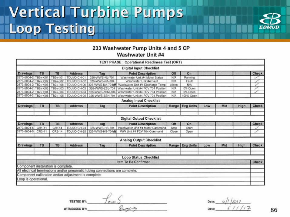
Vertical Turbine Pumps
Loop Testing
87
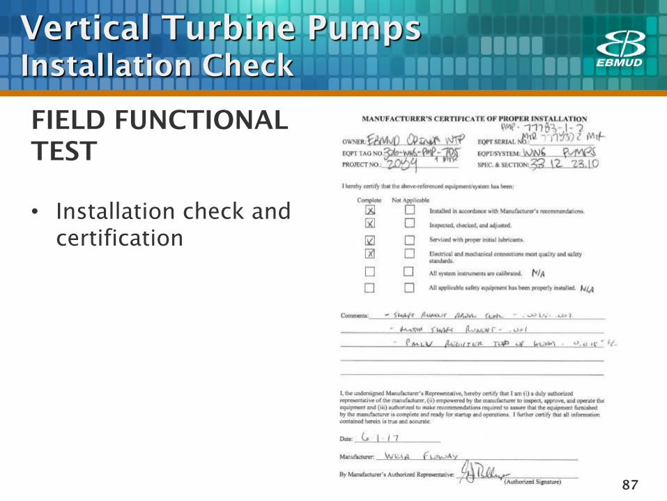
FIELD FUNCTIONAL
TEST
• Installation check and
certification
Vertical Turbine Pumps
Installation Check
88
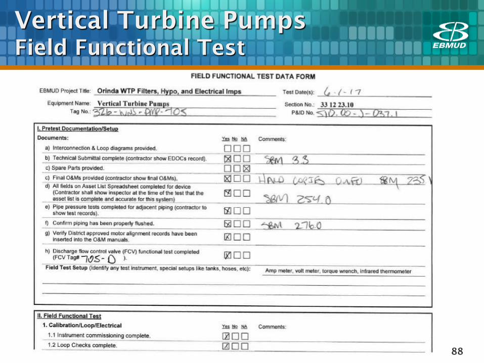
Vertical Turbine Pumps
Field Functional Test
89
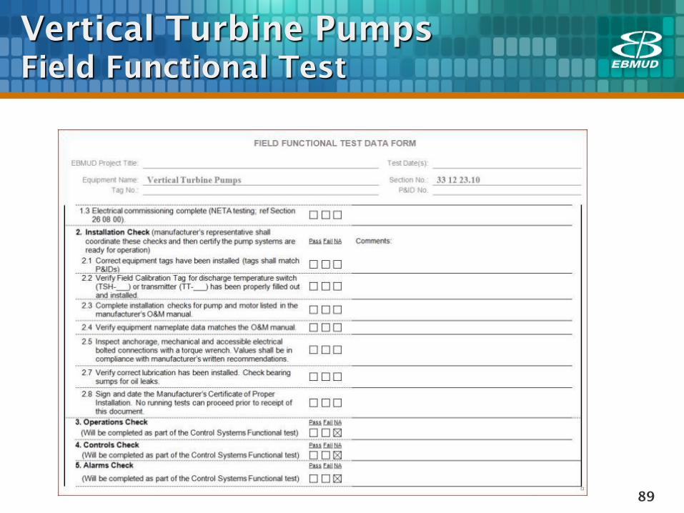
Vertical Turbine Pumps
Field Functional Test
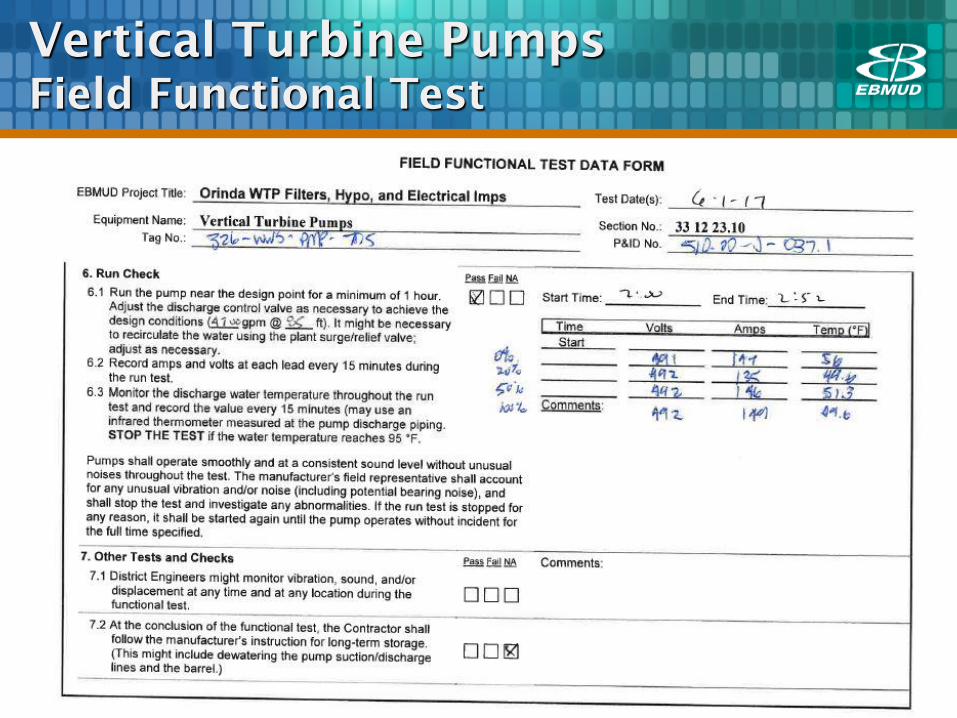
90
Vertical Turbine Pumps
Field Functional Test
91
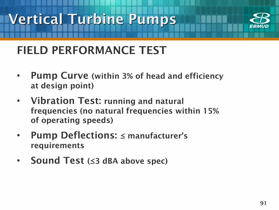
FIELD PERFORMANCE TEST
• Pump Curve (within 3% of head and efficiency
at design point)
• Vibration Test: running and natural
frequencies (no natural frequencies within 15%
of operating speeds)
• Pump Deflections: ≤ manufacturer’s
requirements
• Sound Test (≤3 dBA above spec)
Vertical Turbine Pumps
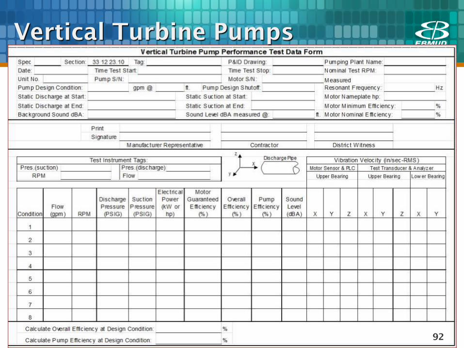
92
Vertical Turbine Pumps
93
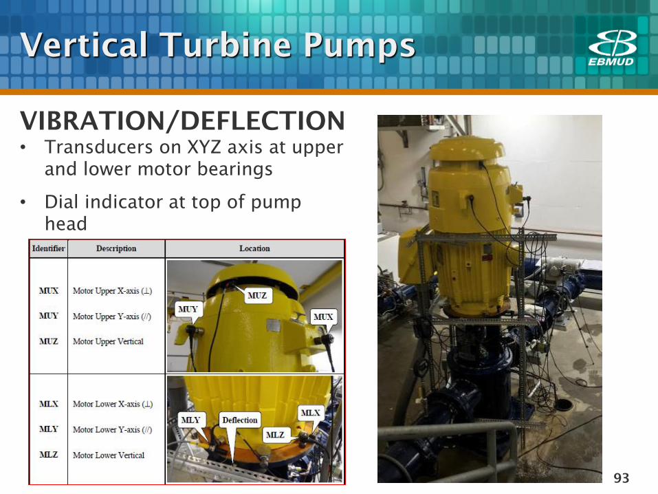
VIBRATION/DEFLECTION
• Transducers on XYZ axis at upper
and lower motor bearings
• Dial indicator at top of pump
head
Vertical Turbine Pumps

94
Vertical Turbine Pumps
NATURAL FREQUENCY TESTING

95
QUESTIONS
Vertical Turbine Pumps –
Mechanical Commissioning
96
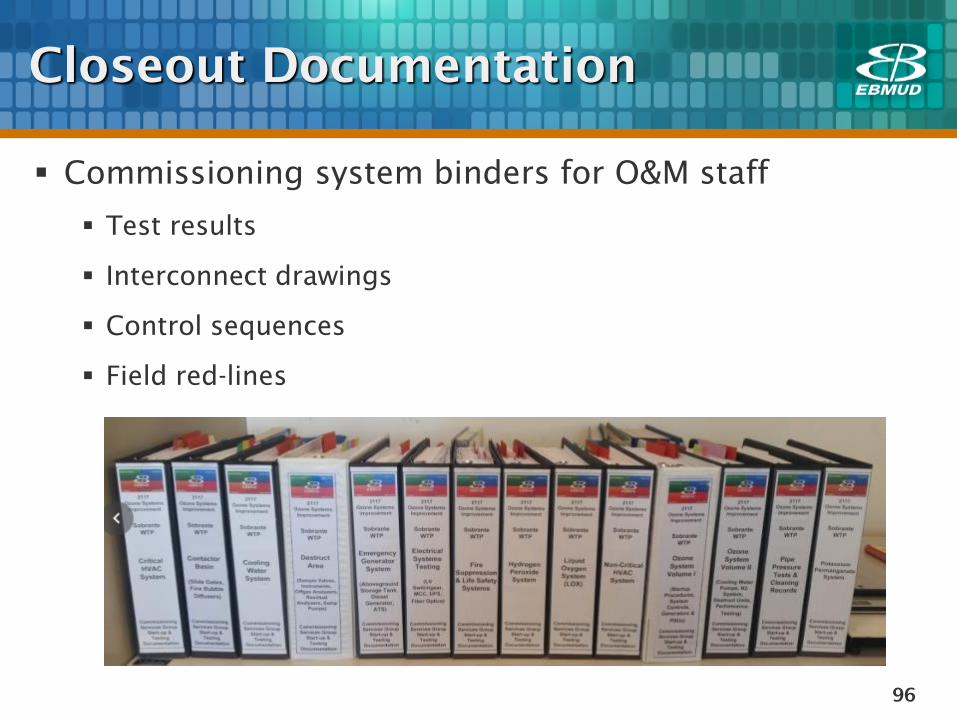
Closeout Documentation
Commissioning system binders for O&M staff
Test results
Interconnect drawings
Control sequences
Field red-lines
97
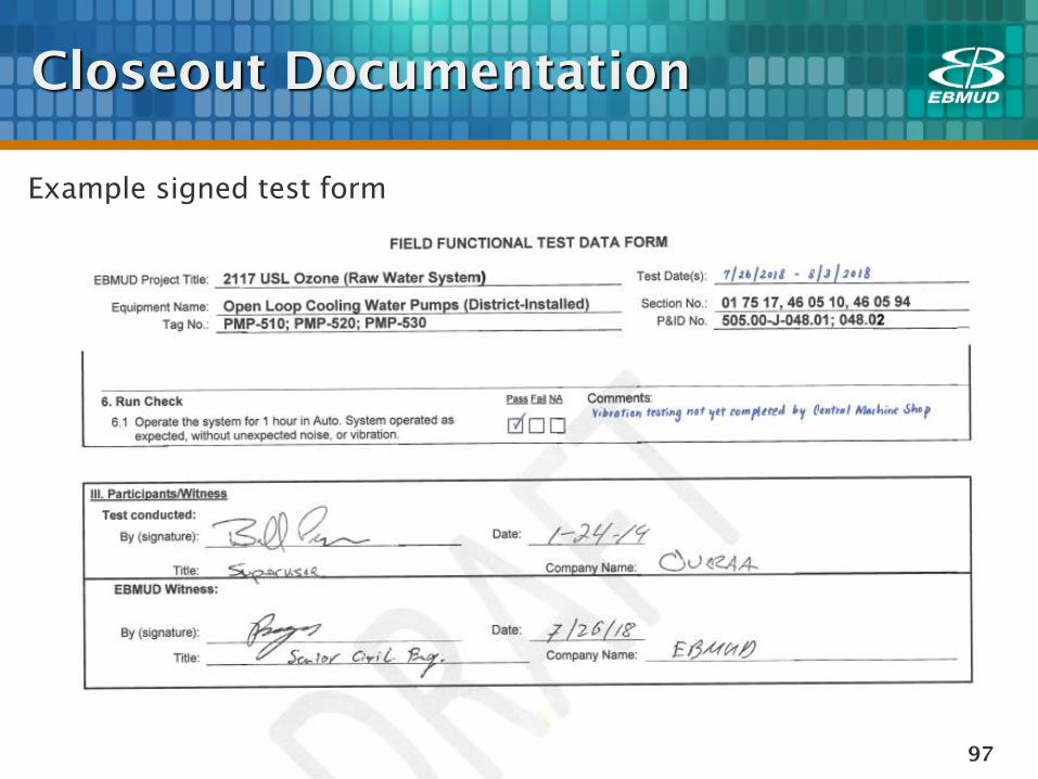
Closeout Documentation
Example signed test form
98
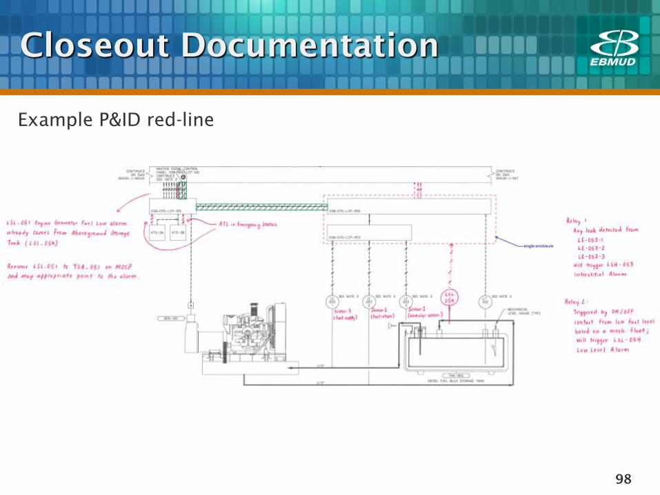
Closeout Documentation
Example P&ID red-line
99
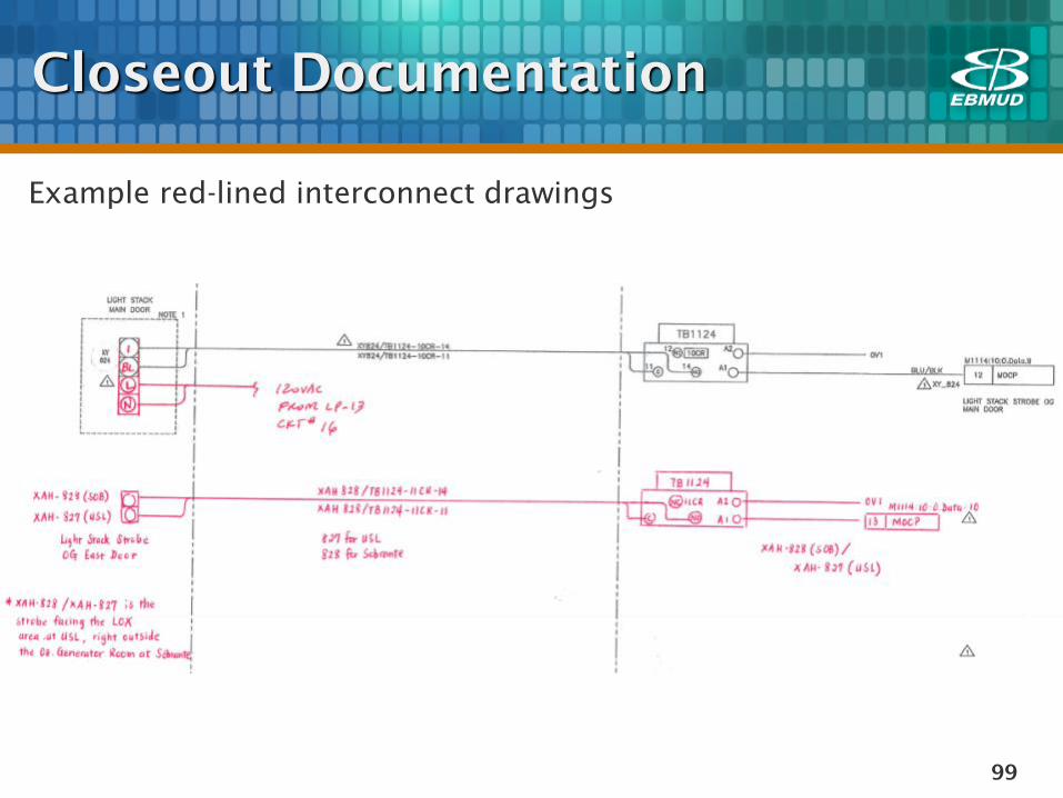
Closeout Documentation
Example red-lined interconnect drawings
Lessons Learned
Roles and Responsibilities
100
Who is the lead: CSG? CM?
Contractor? O&M? Designer or
Consultant?
Decide who leads what efforts
Single-point authority for directing
each commissioning test program
Commissioning coordination memo
to Construction and client clearly
defines roles, responsibilities, and
limitations
Lessons Learned
Design Phase
101
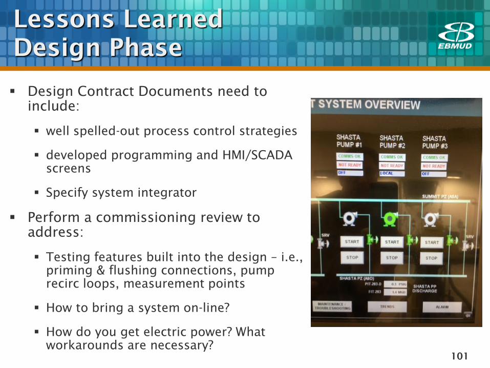
Design Contract Documents need to
include:
well spelled-out process control strategies
developed programming and HMI/SCADA
screens
Specify system integrator
Perform a commissioning review to
address:
Testing features built into the design – i.e.,
priming & flushing connections, pump
recirc loops, measurement points
How to bring a system on-line?
How do you get electric power? What
workarounds are necessary?
Lessons Learned
Construction Phase
102
District CSG to promote understanding of
commissioning process and workflow
Hold commissioning meetings with Construction team and
Contractor (kick off, later – weekly)
Explain Commissioning sequencing and importance of
Functional/Performance tests, Control System Functional Test,
Startup Test
Enforce inclusion of commissioning related tasks in Construction
Schedule and development of a separate, detailed commissioning
schedule
Share commissioning daily reports with O&M staff
Lessons Learned
Construction Phase
103
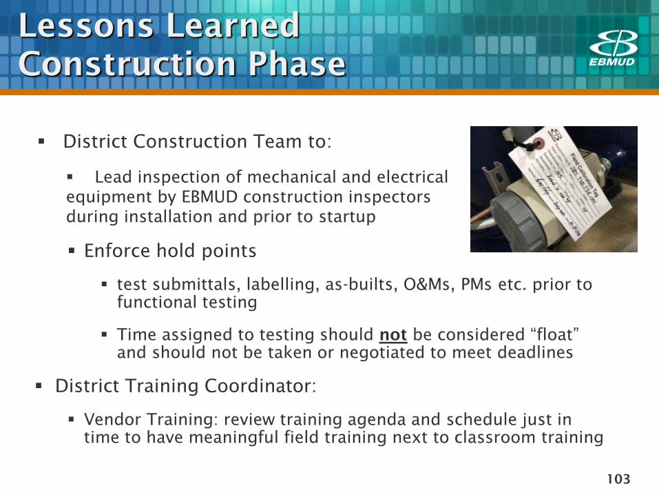
Enforce hold points
test submittals, labelling, as-builts, O&Ms, PMs etc. prior to
functional testing
Time assigned to testing should not be considered “float”
and should not be taken or negotiated to meet deadlines
District Training Coordinator:
Vendor Training: review training agenda and schedule just in
time to have meaningful field training next to classroom training
District Construction Team to:
Lead inspection of mechanical and electrical
equipment by EBMUD construction inspectors
during installation and prior to startup
104
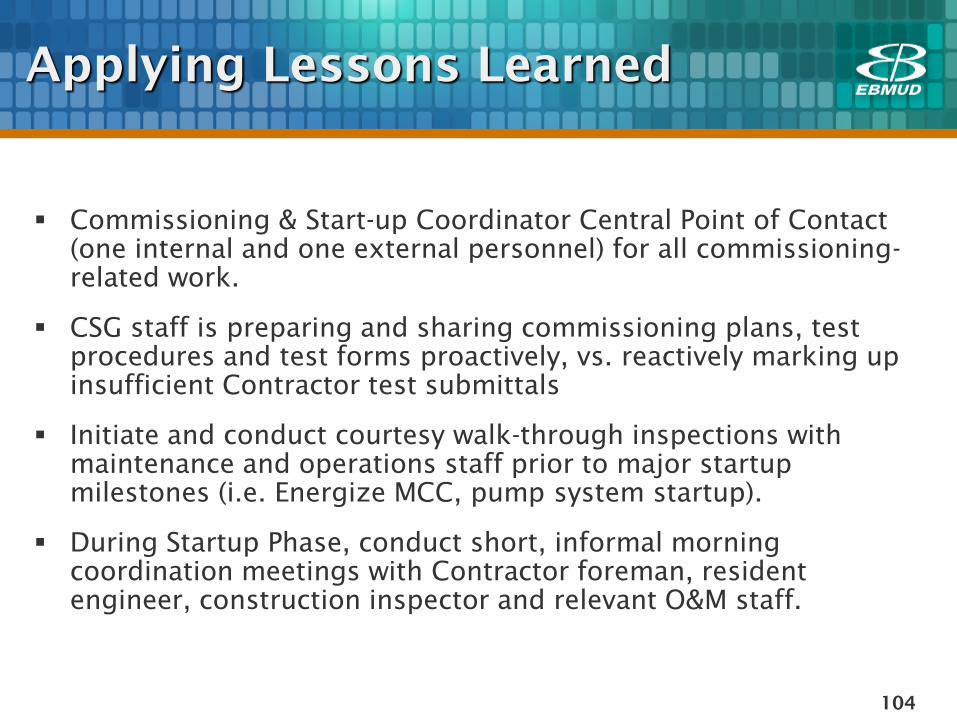
Applying Lessons Learned
Commissioning & Start-up Coordinator Central Point of Contact
(one internal and one external personnel) for all commissioning-
related work.
CSG staff is preparing and sharing commissioning plans, test
procedures and test forms proactively, vs. reactively marking up
insufficient Contractor test submittals
Initiate and conduct courtesy walk-through inspections with
maintenance and operations staff prior to major startup
milestones (i.e. Energize MCC, pump system startup).
During Startup Phase, conduct short, informal morning
coordination meetings with Contractor foreman, resident
engineer, construction inspector and relevant O&M staff.
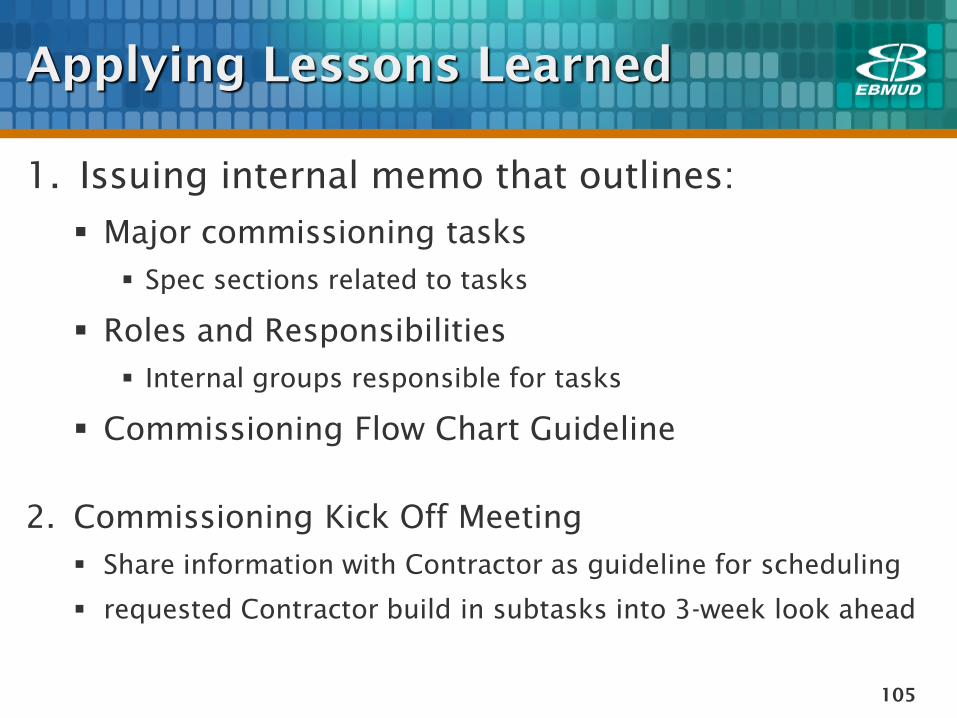
Applying Lessons Learned
1. Issuing internal memo that outlines:
Major commissioning tasks
Spec sections related to tasks
Roles and Responsibilities
Internal groups responsible for tasks
Commissioning Flow Chart Guideline
2. Commissioning Kick Off Meeting
Share information with Contractor as guideline for scheduling
requested Contractor build in subtasks into 3-week look ahead
105
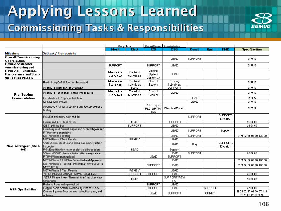
Applying Lessons Learned
Commissioning Tasks & Responsibilities
106
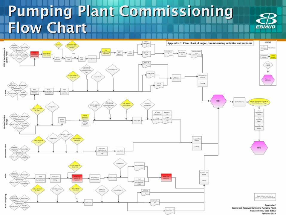
Pumping Plant Commissioning
Flow Chart
107
108
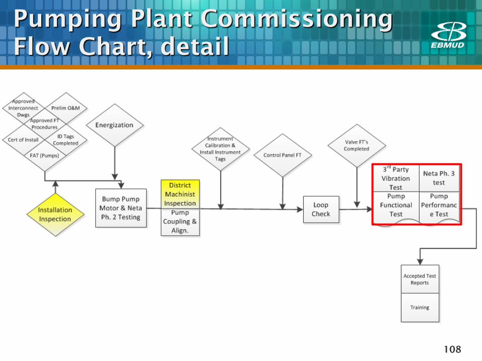
Pumping Plant Commissioning
Flow Chart, detail
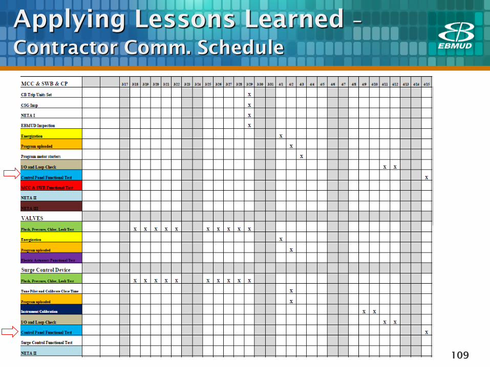
Applying Lessons Learned –
Contractor Comm. Schedule
109
Commissioning
Short/Long Term Goals
110
Train EBMUD construction inspectors in inspection of
electrical and controls equipment
Implement lessons learned from previous CSG
projects in master specs for new in-house and
Consultant-led Design projects
Incorporate commissioning plans and commissioning
sequencing flow charts into Design contract
documents