Commissioning Grid Tied Solar Photovoltaic Systems - …€¦ · · 2015-07-27Commissioning Grid...
72
AABC Commissioning Group AIA Provider Number 50111116 Commissioning Grid Tied Solar Photovoltaic Systems AIA Course Number CXENERGY1525 Ruth Page-Nelson, President, Smart North America, Inc. April 30, 2015
Transcript of Commissioning Grid Tied Solar Photovoltaic Systems - …€¦ · · 2015-07-27Commissioning Grid...
AABC Commissioning Group
AIA Provider Number 50111116
Commissioning Grid Tied
Solar Photovoltaic Systems
AIA Course Number CXENERGY1525
Ruth Page-Nelson, President, Smart North America, Inc.
April 30, 2015
Credit(s) earned on completion of this course will be reported to
AIA CES for AIA members. Certificates of Completion for both AIA
members and non-AIA members are available upon request.
This course is registered with AIA CES for continuing professional
education. As such, it does not include content that may be deemed
or construed to be an approval or endorsement by the AIA of any
material of construction or any method or manner of
handling, using, distributing, or dealing in any material or product.
_______________________________________
Questions related to specific materials, methods, and services will be
addressed at the conclusion of
this presentation.

Copyright Materials
This presentation is protected by US and International Copyright laws.
Reproduction, distribution, display and use of the presentation without written
permission of the speaker is prohibited.
© Smart North America, Inc. 2015

Course Description
This presentation will outline the steps to designing and commissioning grid tied solar photovoltaic systems. The energy production and safety of solar systems is inherently dependent upon multiple factors including observation of regulations covering installations, proper site evaluations, equipment selection, quality of installation (credentials of installers, inspectors, etc.) and the ability for owners/managers to properly maintain equipment.
Course Description Cont.
Many programs including power purchase agreements and funding require certain credentials for installers, qualified commissioning agents as well as ongoing measurement and verification of energy production by qualified persons. This presentation will give an overview of regulations, equipment, training and certification needed to meet the expectations of stakeholders in solar project development and deployment.
Learning ObjectivesAt the end of the this course, participants will be able to:
• 1. Learn the sequence of steps to effectively design and commission grid tied photovoltaic systems.
• 2. Understand the regulations, site requirements, and equipment selection criteria necessary for grid tied photovoltaic systems.
Learning ObjectivesAt the end of the this course, participants will be able to:
• 3. Learn how the quality of installation, and proper maintenance of grid tied photovoltaic systems effect long-term system performance.
• 4. Understand qualifications for commissioning agents and others involved in grid tied photovoltaic systems that are developed under power purchase agreements and other unique funding mechanisms.
STANDARDIZED TRAINING FOR THE SOLAR INDUSTRY
STANDARDIZING SOLAR TRAINING TO THE
INDUSTRY, MAKING SOLAR SAFE AND
EFFICIENT. MADE POSSIBLE BY
A US DEPT. OF ENERGY INITIATIVE

IREC.ORG
Standardized Training is Essential for:
• Designers
• Installers
• Commissioning professionals
• First Responders/Emergency
• Inspectors
• Financing organizations/program mgrs.
• Expected System Performance

Standardized Solar Training for the US and
abroad
Barbados
Wyoming
Alabama
Florida

The Solar Instructor Training Network:
As A part of the SUNSHOT Initiative, The Department of Energy supports the Solar Instructor Training Network (SITN) to ensure that the industry receives the best, standardized SOLAR training available. Training is developed by the Industry’s leading Instructors and Research facilities then provided to the Solar Instructor Training Network Trainers for delivery to the industry.
SUNSHOT is the DOE’s Initiative to
drive down the installed cost of solar
below the cost of traditional electricity
by the 2020 and it is working!
WAS CREATED TO PROVIDE STANDARDIZED TRAINING FOR
SAFE AND EFFICIENT SOLAR INSTALLATIONS
Overview
• This presentation will give an overview of tools, codes and other matters to be considered when designing and commissioning Grid Tied, Solar Photovoltaic Systems
OUTLINE
• Why Standardized Training
• Software and Project Development Tools
• Site Surveys and Pre-Planning
• Commissioning
• Documentation Requirements
• Testing, Inspection, Verification
• Start-up
Right from the Start: Plan for Incentives and Performance
• Plan for Funding requirements
• Power Purchase Agreement requirements vary
• Incentives/Tax Credits
• Aesthetics
• Code Compliance
• Performance
• Structural Limits
• Emergency Response/Standard Equipment Markings and Placement

Online Tools, Developed for public use/government funded
In My Backyard
http://pvwatts.nrel.gov/
http://www.treehugg
er.com/renewable-
energy/imby-online-
tool-estimates-how-
much-renewable-
energy-is-in-your-
backyard.html
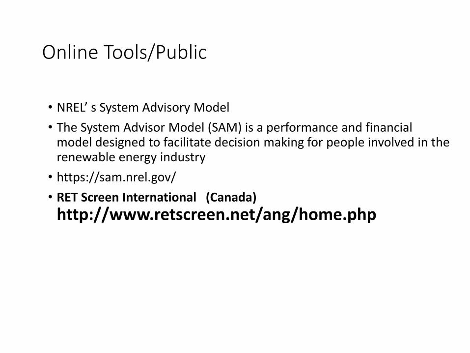
Online Tools/Public
• NREL’ s System Advisory Model
• The System Advisor Model (SAM) is a performance and financial model designed to facilitate decision making for people involved in the renewable energy industry
• https://sam.nrel.gov/
• RET Screen International (Canada)
http://www.retscreen.net/ang/home.php

Online Tools/Public
• Public Domain (NREL/DOE)• PVWATTS: www.nrel.gov/rredc/pvwatts/
• In My Back Yard (IMBY): www.nrel.gov/eis/imby/
• HOMER: www.analysis.nrel.gov/homer/
• Solar Advisor Model (SAM): www.nrel.gov/analysis/sam/
• Commercial• Multiple Commercial Programs are available
• Manufacturers• Inverter string sizing and various system sizing and design tools: manufacturers
normally provide system design support services and may provide stamped engineering plans for your state.
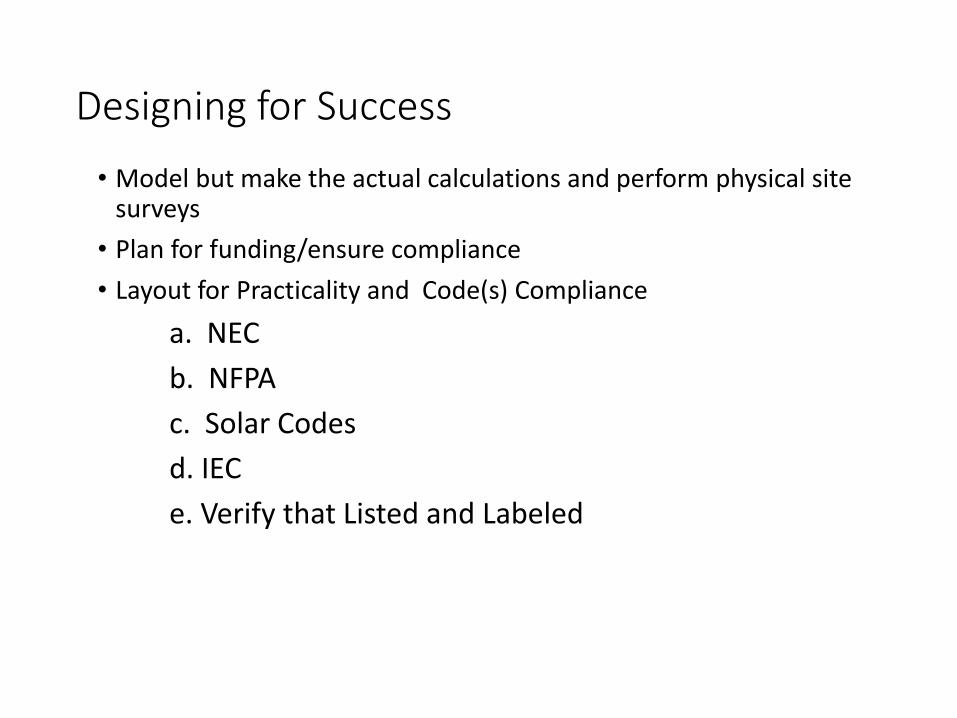
Designing for Success
• Model but make the actual calculations and perform physical site surveys
• Plan for funding/ensure compliance
• Layout for Practicality and Code(s) Compliance
a. NEC
b. NFPA
c. Solar Codes
d. IEC
e. Verify that Listed and Labeled

Other Analytical Tools
• Shading Analysis tools
• Irradiance Data - NASA
• Weather Data-NOAA
• Sun Patterns
• Commissioning (M&V) Tools
• Energy/System Modeling Software
• Energy Efficiency of Structure/BIM
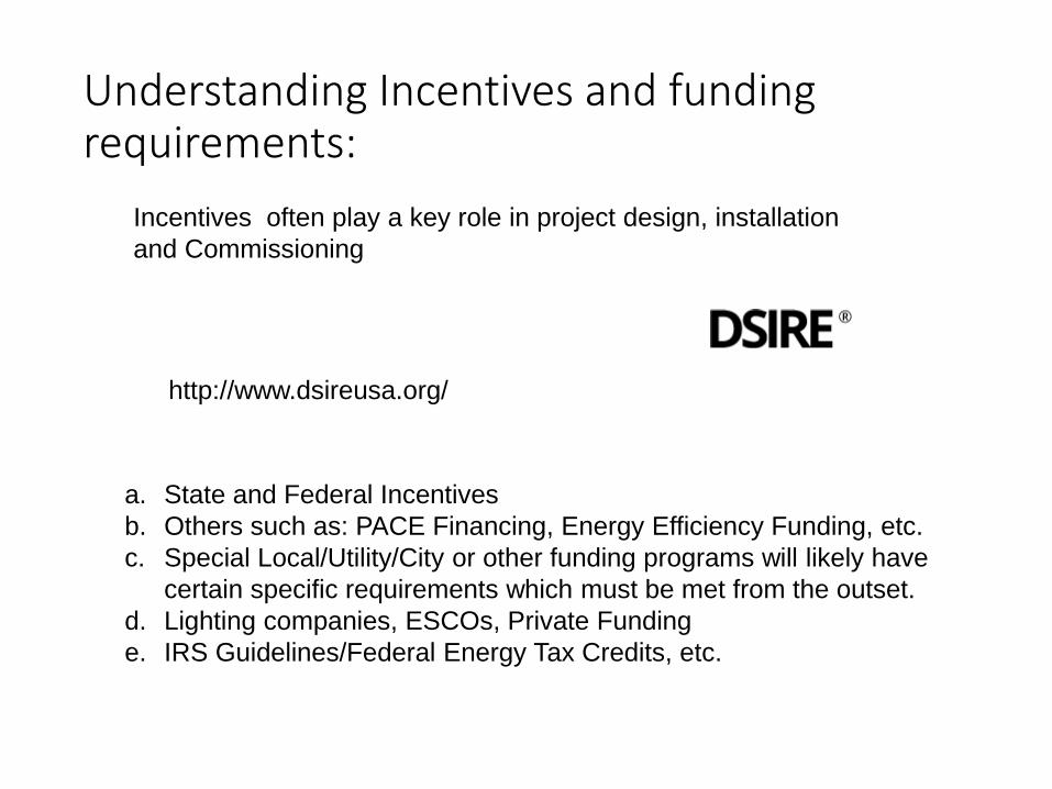
Understanding Incentives and funding requirements:
http://www.dsireusa.org/
a. State and Federal Incentives
b. Others such as: PACE Financing, Energy Efficiency Funding, etc.
c. Special Local/Utility/City or other funding programs will likely have
certain specific requirements which must be met from the outset.
d. Lighting companies, ESCOs, Private Funding
e. IRS Guidelines/Federal Energy Tax Credits, etc.
Incentives often play a key role in project design, installation
and Commissioning
System Types: Interactive and Stand Alone • The sizing principles for interactive and stand-alone PV systems are
based on different design and functional requirements. This Presentation covers Interactive Systems ( Grid Connected).
• Utility-Interactive Systems (without energy storage):• Provide supplemental power to facility loads.
• Failure of PV system does not result in loss of loads.
Stand-Alone Systems
• Stand-Alone Systems (with energy storage):• Designed to meet a specific electrical load requirement.
• Failure of PV system results in loss of load.
• Not tied to the electrical grid
Site Surveys and Preplanning
• Customer Development
• Site Assessment
• Locating PV Arrays
• Shading Analysis
• Project Planning and Preparation
Fundamentals of Solar Radiation
• Sun Patterns
• Solar Radiation Charts/Studies
• Understanding Shading Tools and performing shading analysis
• Positioning panels for optimal performance
Sizing Systems
• Sizing is the basis for PV system electrical designs, and establishes the sizes and ratings of major components needed to meet a certain performance objective.
• The sizing of PV systems may be based on any number of factors, depending on the type of system and its functional requirements.
What limits Sizing:
• The sizing for interactive systems without energy storage generally involves the following
• Size of PV Array
• Inverter Size
• Electrical Service Size
Summary of Sizing basics
• Sizing PV systems is an iterative process used to determine the relative sizes and configurations for major components needed to meet the functional requirements and performance objectives.
• Interactive PV systems are sized independently of loads.

System Sizing
• Several Tools Exist to Assist in System Sizing:
• A. PV Watts
• B. In My Back Yard
• C. SAM System Advisory Model
• D. Ret Screen
System Sizing
• PV array size is limited by available space, budget and inverter voltage requirement/equipment tolerances
• Inverter size is determined by the PV Array Maximum Power
• Size of utility service limits maximum system output
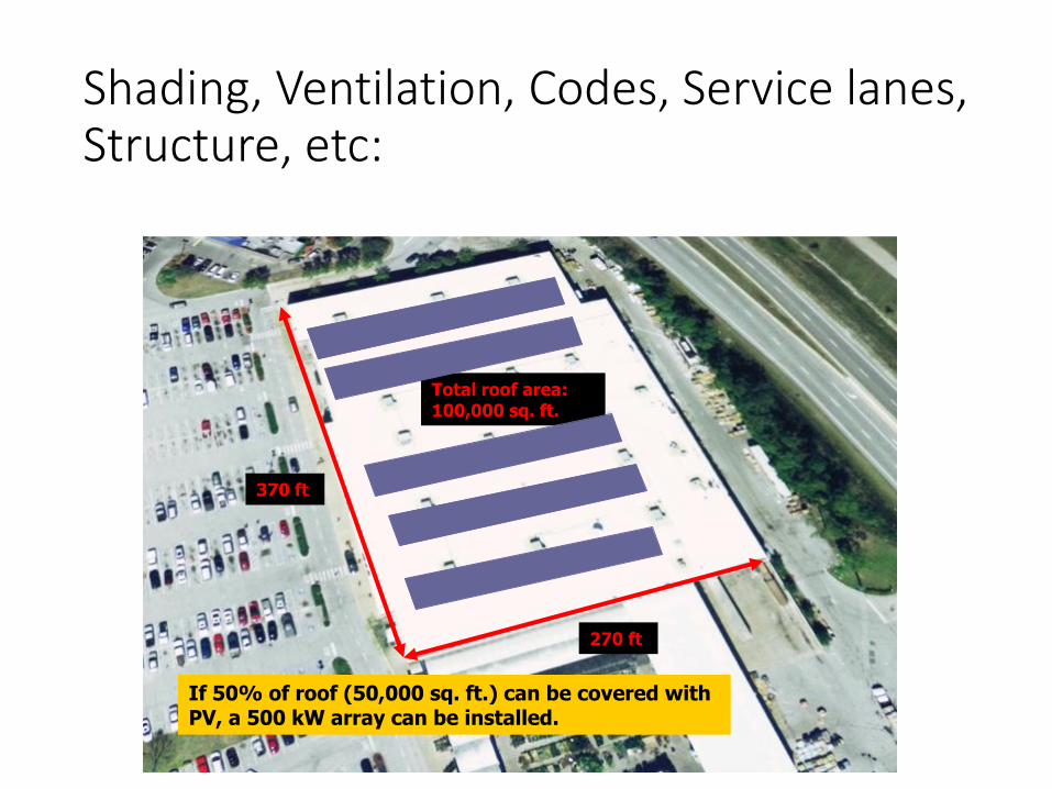
Shading, Ventilation, Codes, Service lanes, Structure, etc:
370 ft
270 ft
Total roof area: 100,000 sq. ft.
If 50% of roof (50,000 sq. ft.) can be covered with PV, a 500 kW array can be installed.
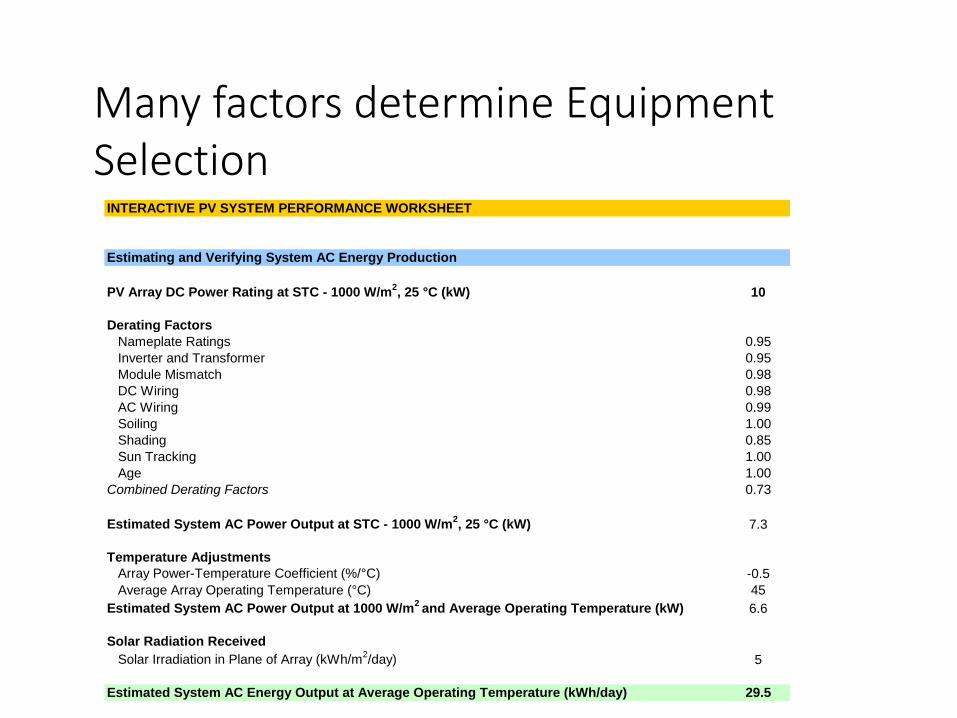
INTERACTIVE PV SYSTEM PERFORMANCE WORKSHEET
Estimating and Verifying System AC Energy Production
PV Array DC Power Rating at STC - 1000 W/m2, 25 °C (kW) 10
Derating Factors
Nameplate Ratings 0.95
Inverter and Transformer 0.95
Module Mismatch 0.98
DC Wiring 0.98
AC Wiring 0.99
Soiling 1.00
Shading 0.85
Sun Tracking 1.00
Age 1.00
Combined Derating Factors 0.73
Estimated System AC Power Output at STC - 1000 W/m2, 25 °C (kW) 7.3
Temperature Adjustments
Array Power-Temperature Coefficient (%/°C) -0.5
Average Array Operating Temperature (°C) 45
Estimated System AC Power Output at 1000 W/m2 and Average Operating Temperature (kW) 6.6
Solar Radiation Received
Solar Irradiation in Plane of Array (kWh/m2/day) 5
Estimated System AC Energy Output at Average Operating Temperature (kWh/day) 29.5
Many factors determine Equipment Selection

Manufacturer Specifications , Location and Balance of Systems must be considered
• Voltage limits of components
• Inverter Performance tolerances
• Location High/Low Temperatures• different geographical locations can see significant voltage changes with the
same components, requiring design changes
• Check inverters, panels and BOS for warranty/system compatibility, voltage and Performance limits
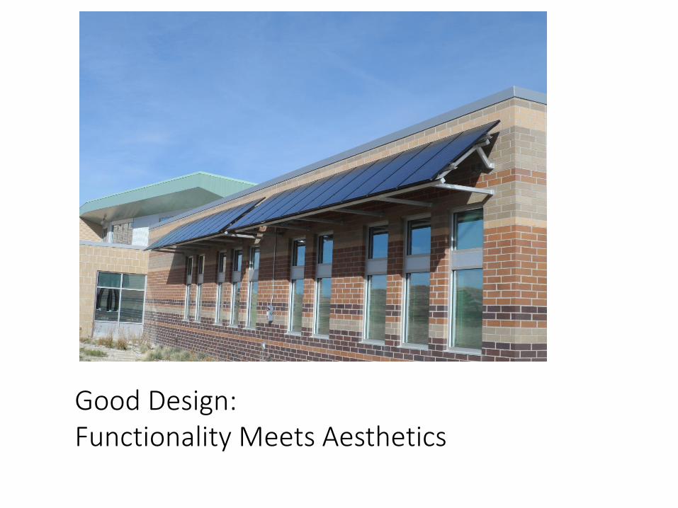
Good Design: Functionality Meets Aesthetics
Steps to Successful PV Installations
• Evaluate site conditions and other factors affecting the planning for PV installations.
• Determine appropriate locations and estimate the size of PV arrays and
• other major components.
• Estimate energy production and conduct value assessments.
Steps to Successful PV Installations
• Identify the requirements for PV system designs and documentation for submittal to building code officials for plan review and permitting.
• Develop monitoring plans and maintenance schedules based on
• component and system requirements.
• Conduct inspections and commissioning tests on PV system installations,
Steps to Successful PV Installations
• interpret the results, troubleshoot problems and determine corrective actions.
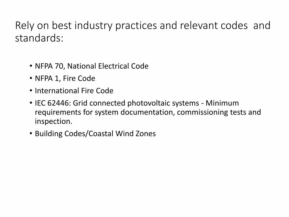
Rely on best industry practices and relevant codes and standards:
• NFPA 70, National Electrical Code
• NFPA 1, Fire Code
• International Fire Code
• IEC 62446: Grid connected photovoltaic systems - Minimum requirements for system documentation, commissioning tests and inspection.
• Building Codes/Coastal Wind Zones

Commissioning Grid Tied PV Systems
• For• A. Engineers
• B. Project Designers
• C. Inspectors
• D. Owners
• F. Financiers
• G. Other Stakeholders
The Importance of Commissioning Solar PV Systems
• PV systems are expected to provide decades of safe and reliable performance.
• However, many PV systems are not satisfactorily evaluated prior to being placed into service,
The Importance of Commissioning PV Systems
• or have regularly scheduled maintenance or testing over their lifetime.
• This often leads to unsafe and underperforming systems
• resulting in increased liability and reduced value to the owners.
The Importance of Commissioning PV Systems
Any electrical system can be tested to verify performance and to evaluate the condition of the wiring systems and equipment. This is particularly important for PV installations, which are subjected to extreme environmental conditions and deteriorating effects of the elements over many years.
Certain DOCUMENTATION IS Always REQUIRED
If it is not written, it is not done!
THE International Electrical Code: Iec 62446 SETS FORTH MIMIMUM DOCUMENTATION REQUIREMENTS FOR GRID CONNECTED SOLAR PHOTOVOLTAIC SYSTEMS.
IEC 62446
• IEC 62446: Grid-Connected Photovoltaic Systems – Minimum Requirements for System Documentation, Commissioning Tests and Inspection.
• Defines minimum documentation, commissioning tests and inspection criteria for grid-connected PV systems
IEC 62446
• This standard is intended to verify the safe and proper operation of PV systems,
• and to serve as a guide for designers, installers and service personnel.
IEC 62446
• Compliance with IEC 62446 provides buyer assurances and correlates with many NEC requirements for the verification of safety for all electrical systems.
IEC 62446 Has Two Main Parts: 1. System documentation
• Describes the minimum documentation that shall be provided to the
• customer following installation of a grid-connected PV system
2. Verification
• Describes the inspections and testing to be conducted for the initial or
• periodic verification of system functions and safety.
•
PV SYSTEM DOCUMENTATION
All PV installations should have adequate documentation
• providing details of the system design and all components and materials used in its construction.
• Proper system documentation helps ensure safe and reliable system operations, and is generally required for the following purposes:
PV SYSTEM DOCUMENTATION
• Plan review and permitting process with local building officials
• Interconnection approval from the local utility
• System installation and maintenance contractors
• System owners and caretakers
• Financing and Incentives

SYSTEM DOCUMENTATION
• Organizing system documentation is a critical part of site surveys and preplanning,
• and is required for building permits,
• utility interconnection and some incentive programs.
SYSTEM DOCUMENTATION
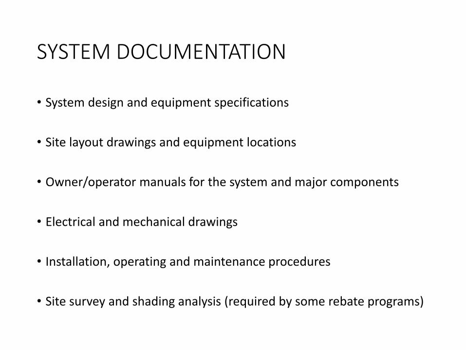
• System design and equipment specifications
• Site layout drawings and equipment locations
• Owner/operator manuals for the system and major components
• Electrical and mechanical drawings
• Installation, operating and maintenance procedures
• Site survey and shading analysis (required by some rebate programs)
SYSTEM DOCUMENTATION
• Electrical and mechanical drawings
• Installation, operating and maintenance procedures
• Site survey and shading analysis (required by some rebate programs)
System Documentation
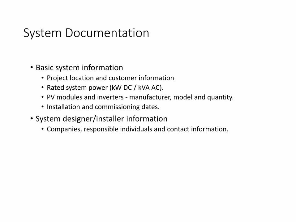
• Basic system information• Project location and customer information
• Rated system power (kW DC / kVA AC).
• PV modules and inverters - manufacturer, model and quantity.
• Installation and commissioning dates.
• System designer/installer information• Companies, responsible individuals and contact information.

System Documentation
• Wiring diagrams (cont.)• AC system
• AC disconnect location, type and rating.
• AC overcurrent protective device location, type and rating.
• Datasheets• Modules and inverters
• Mechanical design information• Data sheet for the array mounting system.
Documentation
• Operation and maintenance information
• Test results and commissioning data• Copies of all test and commissioning data shall be provided (see Clause 5 of
IEC 62446 standard
Verification
• Verification of a grid-connected PV system should be done with reference to the applicable standards (IEC 60364-6 or NFPA 70B), which provides the requirements for initial and periodic verification of any electrical installation.
• Initial verification takes place upon completion of a new installation or completion of additions or of alterations to existing installations.
Verification
• Periodic verification is to determine whether the installation and equipment remain in a satisfactory condition for use.
• Initial and periodic verifications shall be made by a skilled person, competent in verification.
Verification Reports IEC 62446
• Verification reports• Summary information describing the system (name, address, etc.).
• A list of the circuits that have been inspected and tested.
• A record of the inspection.
• A record of the test results for each circuit tested.
Verification Reports cont.
• Recommended interval until next verification.
• Signature of the person(s) undertaking the verification.
• Model verification reports are provided in Annexes to IEC 62446.
Inspection
• General• Visual inspections are conducted prior to energizing the installation and
electrical testing.
• DC system inspection• Verify that the DC circuits and components have been designed, specified
and installed to the applicable code requirements

Inspection
• have appropriate DC ratings and required labeling, including:• PV modules
• Wiring methods
• Overcurrent devices
• Disconnecting means
• Grounding and bonding equipment
Inspection
• AC system inspection• Verify that the AC circuits and components have been designed, specified and
installed to the applicable code requirements, and have appropriate ratings and required labeling, including:
• Inverters
• Wiring methods
• Overcurrent devices
• Disconnecting means
• Grounding and bonding equipment
Labeling
• Inspections shall also verify proper labeling of the system and components, including:
• All code-required listings and labels for major components, wiring methods, overcurrent devices, disconnecting means and terminations.

Labeling
• IEC 62446 additionally requires the following to be displayed on site:• A single line wiring diagram
• Inverter settings (as applicable)
• installer details
• Emergency shutdown procedures
• All signs and labels shall be suitably affixed and durable.
Testing
• General• Tests AC circuits according to standards (IEC 60364-6 or NFPA 70B)
• PV array and DC circuits:• Continuity of grounding and bonding conductors
• Polarity test
Testing
• String open-circuit voltage test
• String short-circuit current test
• Functional tests
• Insulation resistance
Testing
• Continuity and resistance testing verifies the integrity of grounding and bonding systems, conductors, connections and other terminations.
• Polarity testing verifies the correct polarity for PV dc circuits, and proper terminations for dc utilization equipment.

Testing
• Voltage and current testing verifies that PV array and system operating parameters are within specifications.
• Insulation resistance testing verifies the integrity of wiring and equipment, and used to detect degradation and faults to wiring insulation.
Testing
• Performance testing verifies the system power and energy output are consistent with expectations.
• Remember All Tests should be performed by qualified persons using proper PPE and safety procedures!!!
System Start-UP • The initial start up for a PV system is conducted after all inspections
and checks have been completed with all outstanding items resolved.
• Start up procedures include:• Installing overcurrent devices
• Closing all DC and AC disconnects and turning on inverter
• Verifying output

This concludes The American Institute of Architects
Continuing Education Systems Course
Smart North America, Inc.
Ruth Page-Nelson-President
www.smartnorthamerica.com
Office: 800-764-3085
Cell 334-685-0420


![Design of Grid-Connected Photovoltaic System · weight of photovoltaic system [7]. The grid[6] -connected photovoltaic systems also need the inverters for power conversion, grid interconnection](https://static.fdocuments.in/doc/165x107/5fba0adb999fbb3bbe303c6e/design-of-grid-connected-photovoltaic-system-weight-of-photovoltaic-system-7.jpg)