Commissioning
65
Commissioning & Maintenance of Protective Relays
-
Upload
mahmoud-ibrahim-shaker -
Category
Education
-
view
20 -
download
6
Transcript of Commissioning

Commissioning & Maintenanceof Protective Relays

Test Options (1)
1. Primary injection sensitivity tests only
Minimum of time consumed
If results incorrect, secondary injection and CT tests requiredUnable to check :-
a. Adequate timing curves
b. Directional properties
c. Power and impedance relays
Not suitable for maintenance tests

Test Options (2)
2. Secondary injection tests(But with C.T.’s still connected)
True primary sensitivity easily equated
If results incorrect isolated relay and CT mag. curve checks necessary
Ref. for maint., but system outage required
Primary tests on C.T. ratio and polarity still required on commissioning

Test Options (3)
3. Secondary injection tests(But with relays isolated by test facility)
Proof of isolated relay characteristic obtained
Ref. for maintenance obtained(relay if necessary tested with system on load)
Full primary injection/on load tests done oninitial commissioning only

Test Options (4)
4. On load tests
Checks that expected C.T. / V.T. quantitiespresent at test facility
Scheme stability for external faults
Proof of correct directional characteristics

Summary
Areva’s preference:-
1. Secondary injection (isolated relay)
2. Primary injection (incl. C.T. ratio, phasing and mag. curve)
3. On load tests

Site Testing and Commissioningof Protection Equipment
To assure ourselves, and the interested authorities, that the overall protective system functions correctly
Resist pressures to take risks
Study wiring diagrams and protection requirements
Key diagram
Delegate responsibilities
Observe safety of self and others
Commissioning Flow ChartSummary (1)
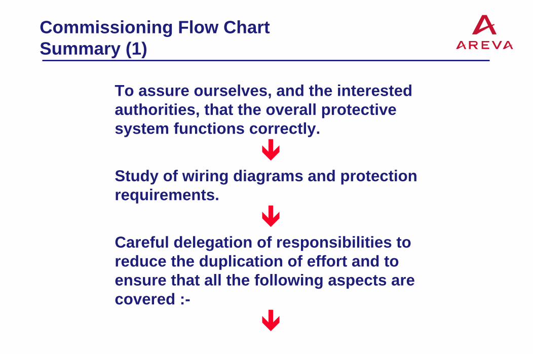
To assure ourselves, and the interested authorities, that the overall protective system functions correctly.
Study of wiring diagrams and protection requirements.
Careful delegation of responsibilities to reduce the duplication of effort and to ensure that all the following aspects are covered :-

Commissioning Flow ChartSummary (2)
Insulation Tests
Secondary Injection Tests (Relay Tests)
Ensure clean dust free areaMechanical inspectionOut-going contact wiringExternal resistorsC.T. shorting and isolating switchesContact follow-through and pressuresElectrical checks on each basic electrical function to
prove satisfactory operationProve trip and alarm circuitsTest results (record and maintenance purposes)

Commissioning Flow ChartSummary (3)
Primary injection tests
D.C. flick tests on C.T.’s
C.T. mag curve tests
C.T. ratio and polarity tests
Primary sensitivity tests
Stability tests
Test results

Commissioning Flow ChartSummary (4)
Line / Transformer / Generator energisation
V.T. ratio and phasing tests
On load testsStability testsDirectional properties
At the end of each stage ask yourself :-
Is there anything wrong, wiring or otherwise, that I have not checked that may prevent correct operation?
If so, CHECK IT OUT !

Peak 1.6 x AV.
Average D.C.
0V.
Peak to Peak V
<12% of mean D.C. comp.0V.
Mean D.C.
Measuring instrumentsD.C. auxiliary supplies
Faulty relays
Maintenance ofProtective Relays (1)
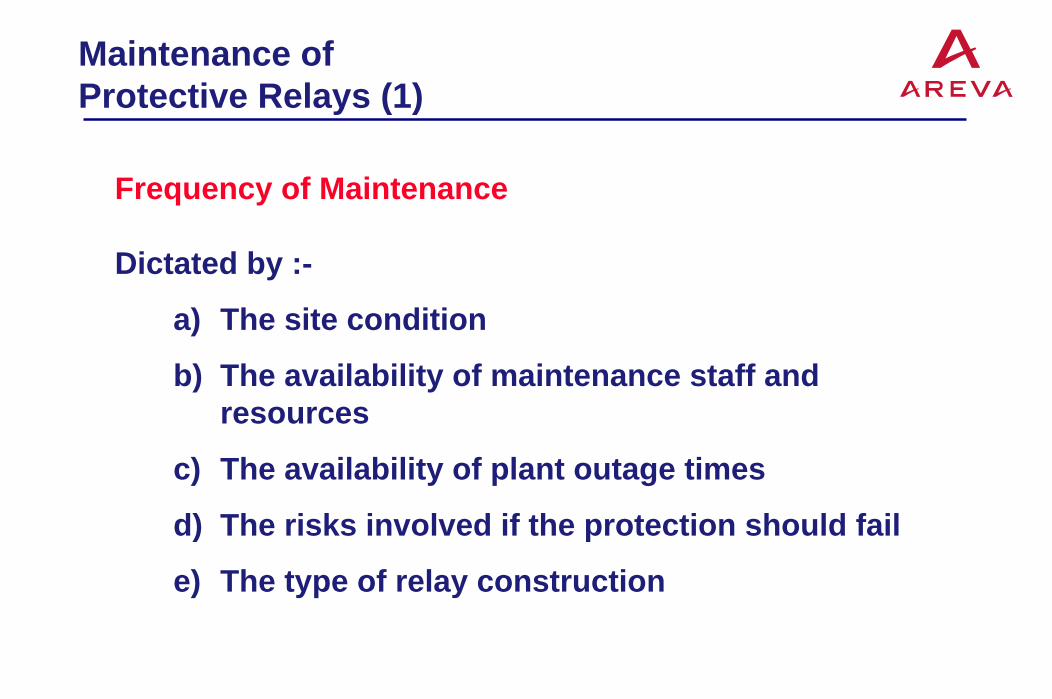
Frequency of Maintenance
Dictated by :-
a) The site condition
b) The availability of maintenance staff and resources
c) The availability of plant outage times
d) The risks involved if the protection should fail
e) The type of relay construction
Maintenance ofProtective Relays (2)
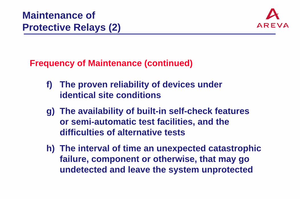
Frequency of Maintenance (continued)
f) The proven reliability of devices under identical site conditions
g) The availability of built-in self-check features or semi-automatic test facilities, and the difficulties of alternative tests
h) The interval of time an unexpected catastrophic failure, component or otherwise, that may go undetected and leave the system unprotected

Maintenance ofProtective Relays (3)
Onerous site conditions :-
1. Dusty or dirty environments2. Corrosive chemical atmospheres3. Frequent or continuous vibration4. High humidity5. High or cycling temperatures6. Consistently high levels of energising or auxiliary
quantities
Typically maintain every 12-18 months under ideal conditions and decrease frequency

Maintenance ofProtective Relays (4)
Visual inspections
The commissioning test stage
At each maintenance test
After heavy fault clearance
More regularly if onerous site conditions
Calibration tests
Trip testing

Maintenance ofProtective Relays (5)
Recommended maintenance tests
Instruction manuals
Record relay settings
Visual inspection
Secondary injection tests
Contact integrity
Return to ‘in-service’ settings
Check energising quantities

Maintenance ofProtective Relays (6)
Relays involving static (electronic) components
Electro-static discharge (ESD)
Wrist straps
Modern static relays (K-SERIES, MiCOM etc.)
Fault find to board level only
Protect boards

Corrective Maintenance ofProtective Relays (1)
Cleaning solvents
Trichlortrifluorethane (Ozone damaging)(Arklone, Freon, Flourisol and Supersolve)
PROZONE
Contact lubricants and other lubricants
Contact cleaning burnishers
Contact pressures and settings
Dust removal
Relay recalibration (Why?)

Contents of Section 23 of ‘PRAG’ (1)(Protective Relay Application Guide)
Insulation tests
Current transformer tests
Voltage transformer tests
Test facilities
Secondary injection tests O.C. and E.F.DifferentialPilot wiresNegative phase sequenceDirectional
DistanceD.C. operated

Contents of Section 23 of ‘PRAG’ (2)(Protective Relay Application Guide)
Primary Injection Test (+ on load tests)
O.C. and E.F. relays
Directional
Generator Differential
Transformer Differential
Restricted E.F.
Pilot Wire
Busbar
Negative phase sequence

Contents of Section 23 of ‘PRAG’ (3)(Protective Relay Application Guide)
Tripping and Alarm Annunciation
Periodic Maintenance
In addition to PRAG :-
Consult instruction manuals


Test Terminal Block
To relay coils
To main VTTo maincurrent
transformers
To CT testwindings(if any)
A B C A B C N A B C N
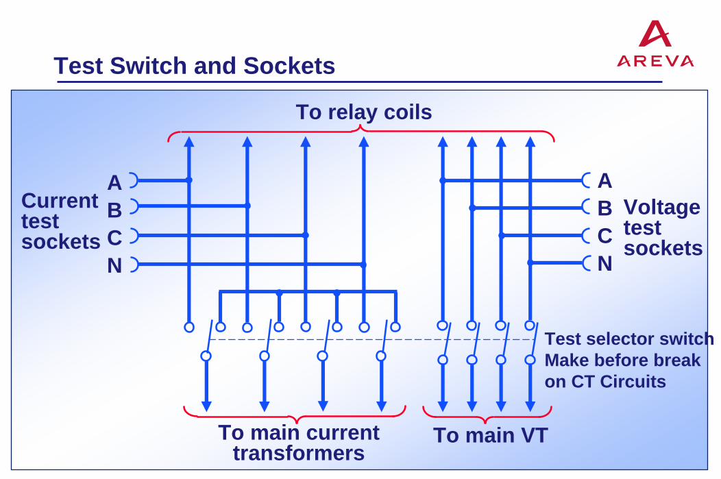
Test Switch and Sockets
To relay coils
To main currenttransformers
To main VT
ABCN
ABCN
Currenttestsockets
Voltagetestsockets
Test selector switchMake before break on CT Circuits

Current TransformerPolarity Check
P2 P1
S1S2 +-
Pushbuttonswitch
Battery
+- A

Current TransformerRatio Check
A B CA2
A1
P1 S1
S2P2
Primary injectiontest set
250V AC supply
Relay or test blockcontact fingers
51
Test pluginsulation
64
51
51
Temporaryshortcircuit

Testing Current TransformerMagnetizing Curve
A B C
P1S1
S2
P2
V
Test plug isolatingcurrent transformersfrom relay coils
Variabletransformer250V 8A
250VA Csupply
Step-up transformerif required
Main circuitbreaker open
To relaycoils
A
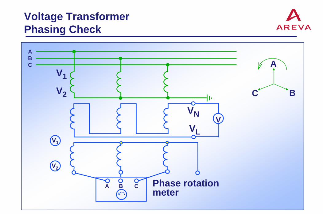
Voltage TransformerPhasing Check
ABC
V1
V2
VN
VLV
A B C Phase rotationmeter
A
BC
V1
V2

Overcurrent Test Set
K2
K1
ARangeadjusting CT
Coarsecontrolreactor
Fine controlvariabletransformer
250VA Csupply
Supplyswitch
Backingtransformer10% control
Mediumcontrolreactor
Injectiontransformer
Starttimer
Stoptimer
51
I
Relaycoil
Relay short-circuiting switch
Relay current I = Ammeter reading (A) x K1 K2

Basic Current Control Circuitof CFBA Test-Set
220/250VACSupply50/60Hz
Thermal Overload / OvervoltageProtection
SupplyContractor
Supply ShortingSwitch Timer
Start(Break to Start)
L1 L2
10X
Variac V1
Injection‘Matching’C.T.
O/V
Det
ecto
rC
ircui
t OutputtoRelay
5X 2X 1X
60Hz
50Hz
60Hz
50Hz
T1
0.1A
0.2A
0.5A
1A
2A
5A
10A
A
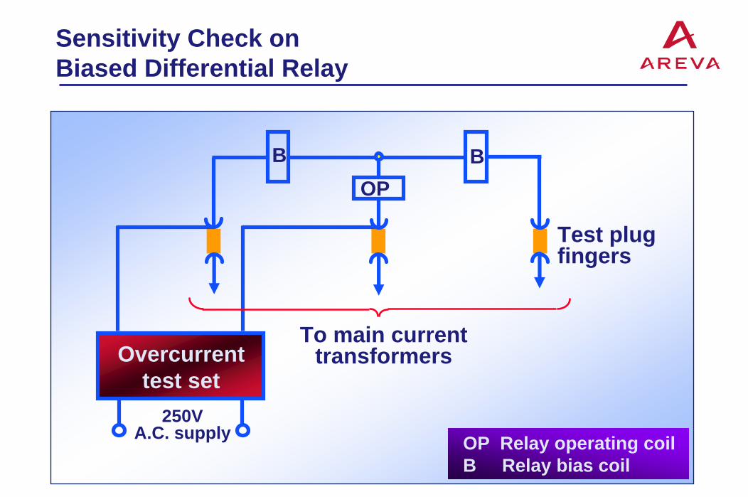
Sensitivity Check onBiased Differential Relay
Test plugfingers
B BOP
To main currenttransformersOvercurrent
test set250V
A.C. supply OP Relay operating coilB Relay bias coil

Testing Bias Characteristics(Using Overcurrent Test Set)
To main currenttransformers
B BOP
I1+I2
A1
I2
A2
R
Test plugfingers
I1
250V A.C.supply
Overcurrenttest set

Testing Relay Bias Characteristic(Using Resistances)
To main currenttransformers
B BOP
I1+I2
A1
I2
A2
R1 R2
Test plugfingers
I1
250V A.C.supply
A1 and A2 AmmetersOP Relay operating coilB Relay bias coil

Sensitivity Test
Testplug
Feeder isolated
BOP
Pilots
Overcurrenttest set
250VA.C. supply
ABC
Relaycontactfingers
BOP

Testing Sensitivity of NegativePhase Sequence Relay
A
B
C
NOvercurrenttest set
46
Filternetwork
Relaycoil
Test plugin test block
250V A.C.supply
To maincurrenttransformers
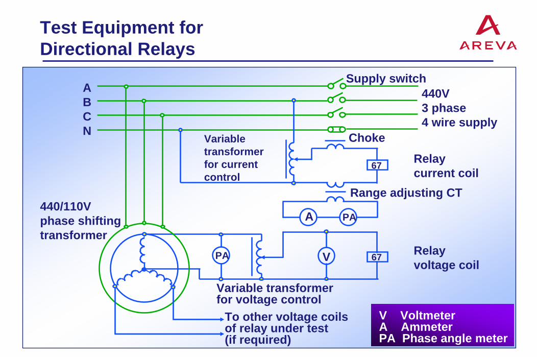
Test Equipment forDirectional Relays
V VoltmeterA AmmeterPA Phase angle meter
To other voltage coilsof relay under test(if required)
ABCN
Variabletransformerfor currentcontrol
Choke
440V3 phase4 wire supply
67
67
Relaycurrent coil
Range adjusting CT
PAA
VPA Relayvoltage coil
Variable transformerfor voltage control
440/110Vphase shiftingtransformer
Supply switch

Primary Injection Test Set
250V A.C.supply
A
Variable transformer 40AInjection transformer250/10 + 10 + 10V10kVA
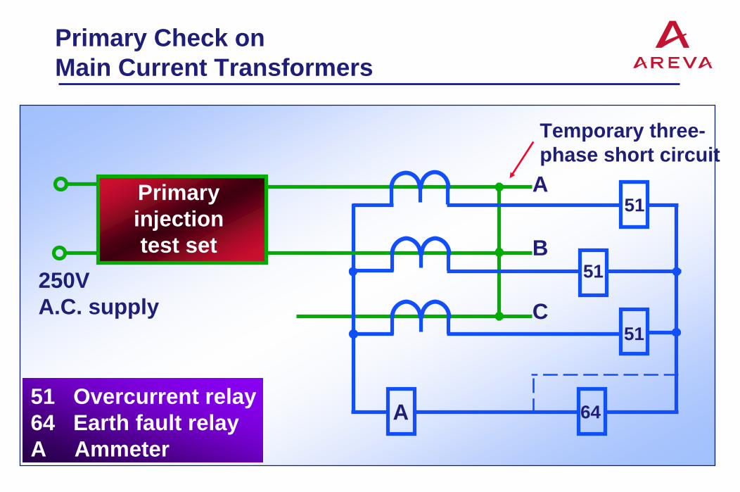
Primary Check onMain Current Transformers
Temporary three-phase short circuit
Primaryinjectiontest set
250VA.C. supply
A
B
C
51
51
51
64A51 Overcurrent relay64 Earth fault relayA Ammeter

Sensitivity Test onEarth Fault Relay
51
51
250VA.C.supply
A
B
C
51
64
Primary injectiontest set

Load Test on DirectionalOvercurrent Relays
Load current
A
B
C
Direction of power flowfor relay operation
PAPA
AV
Directional overcurrent relays
A AmmeterV VoltmeterPA Phase angle
meter
A AmmeterV VoltmeterPA Phase angle
meter
A B C
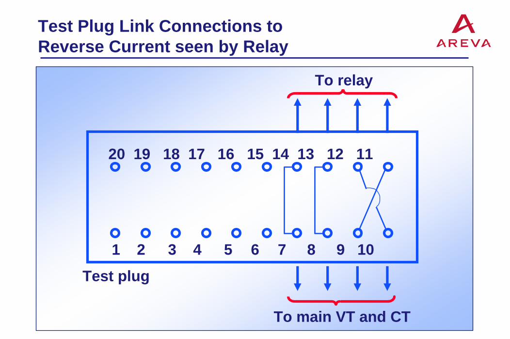
Test Plug Link Connections toReverse Current seen by Relay
To relay
To main VT and CT
20 19 18 17 16 15 14 13 12 11
1 2 3 4 5 6 7 8 9 10
Test plug

Load Test on DirectionalEarth Fault Relay
A AmmeterV VoltmeterPA Phase angle meter
A
PA V
PA
A B C P1 P2
S1 S2
IA
5151
51
V1V2
VL VN
Temporaryshort circuitconnections
Insulating strips inrelay or test blockcontact fingers
Directional earthfault relay
Load current

Testing Sensitivity of Generator Differential Protection Using Primary Injection Test
ABC
87 Generator differential relayV VoltmeterA Ammeter
Primary injectiontest set
250V A.C. supply
Generator Isolating links
87V 87
A
87

Testing Sensitivity of Generator Differential Protection Using Generator to Supply Primary Current
87 Generator differential relayV Voltmeter
GeneratorIsolatinglinks
ABC
Temporaryshort circuit
87V 8787

Checking Stability of Generator Differential Protection
ABC
87 Generator differential relayA Ammeter
GeneratorIsolating
linksTemporaryshort circuit
87
A
8787
AA
Shorts across relay/stabilising resistors

Earth Fault Sensitivity Check on Transformer Differential Protection
Temporaryshort circuit
A
250VA.C.supply
Primaryinjectiontest set
Operatingcoils
87 87 87
Bias coils
ABC

Phase Fault Sensitivity Check on Transformer Differential Protection
Temporaryshort circuitA
250VA.C.supply
Primaryinjectiontest set
Operatingcoils
87 87 87
Bias coils
ABC

Stability Check on TransformerDifferential Protection
Temporary short circuitGenerator
87 8787
Bias coilsA
~
Operating coilsInstantaneous current distribution for three-phase short circuit with phase A current at maximum
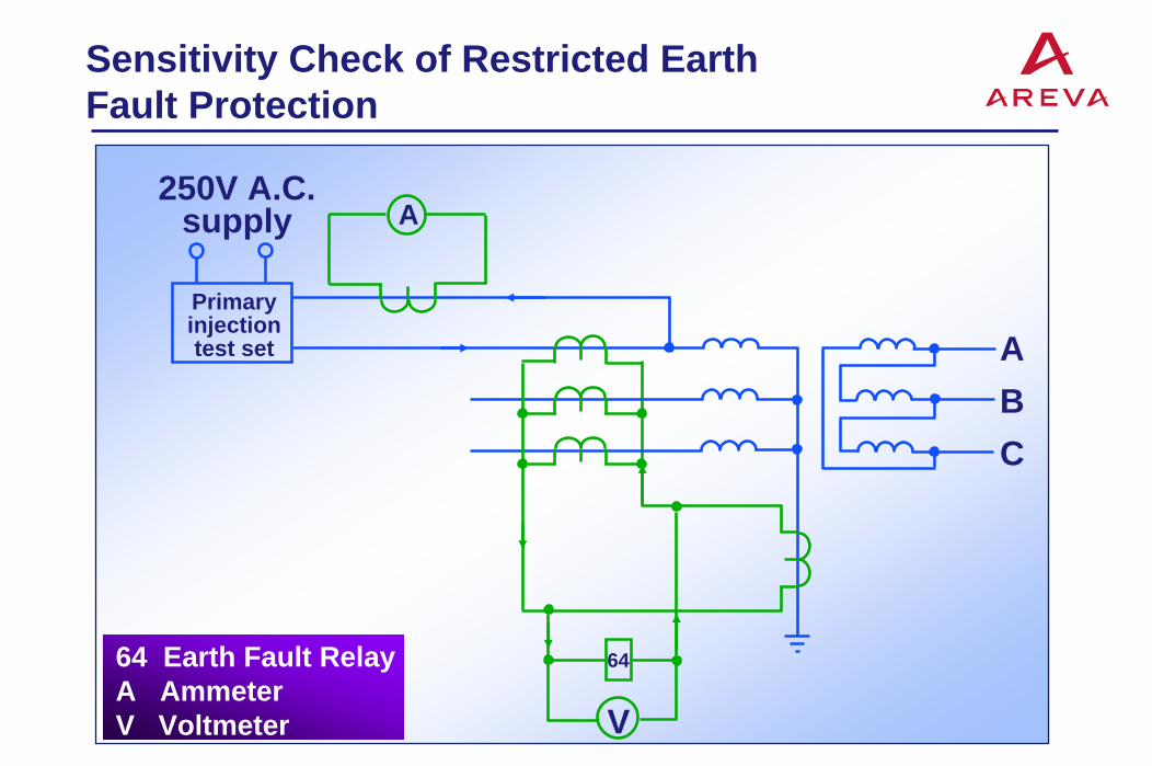
Sensitivity Check of Restricted Earth Fault Protection
A250V A.C.
supply
Primaryinjectiontest set A
BC
64
V
64 Earth Fault RelayA AmmeterV Voltmeter

Stability Check of Restricted Earth Fault Protection
64 Earth Fault RelayA Ammeter
250V A.C. supply
Primaryinjectiontest set A
BC
64
A Temporary short circuit
A

Sensitivity Check of Negative Phase Sequence Relay
46 Negative phase sequence relayA Ammeter
250VA.C. supply
Primary injectiontest set
A B C
A
Filternetwork 46
Temporary short circuit

Test Plug Link Connections forLoad Current Test
To relayfilter network
20 19 18 17 16 15 14 13 12 11
1 2 3 4 5 6 7 8 9 10
A B C N

Earth Fault Sensitivity Check of Pilot Wire Relay
B Relay bias coil OP Relay operating coil A Ammeter
A
B
C
250V A.C. supply
Primary injectiontest set
A
B
OPPilots to remoteend relay

Phase Fault Sensitivity Checkof Pilot Wire Relay
B Relay bias coilOP Relay operating coilA Ammeter
A B C
Primary injectiontest set
A
OP
Pilots to remoteend relay
B
250V A.C. supply

Load Current Distribution
Instantaneous currentdistribution of three-phasebalanced load withphase A current atmaximum
A B C A B CFeeder
B
OP
BOP
Pilots
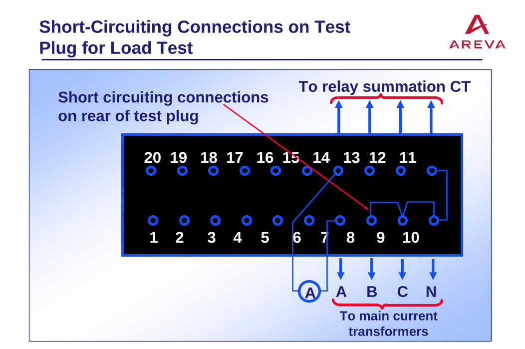
Short-Circuiting Connections on Test Plug for Load Test
To relay summation CT
A B C N
20 19 18 17 16 15 14 13 12 11
1 2 3 4 5 6 7 8 9 10
Short circuiting connectionson rear of test plug
To main currenttransformers
A
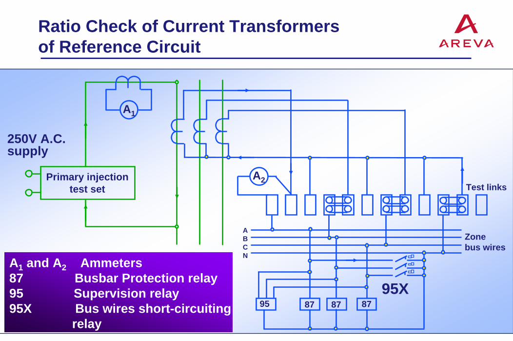
Ratio Check of Current Transformersof Reference Circuit
A1 and A2 Ammeters87 Busbar Protection relay95 Supervision relay95X Bus wires short-circuiting
relay87 878795
95X
ABCN
A2
Zonebus wires
Test linksPrimary injection
test set
A1
250V A.C.supply

Polarity Check of Reference CircuitCurrent Transformers
A Ammeter87 Busbar Protection
relay95 Supervision relay95X Bus wires short-
circuiting relay
87 878795
95X
ABCN
A
Zonebus wires
Test links
Primary injectiontest set
A250V A.C.supply
Temporary short circuitA B C

CT Inter-Group Ratio and Polarity Check in Busbar Protection Scheme
A1 Ammeter for ratio checkA2 Ammeter for polarity
check87 Busbar protection relay95 Supervision relay95X Bus wires short-
circuiting relay
250V
A.C
. sup
ply
Temporary short circuit
Prim
ary
inje
ctio
nte
st s
et
ABCN
A
A1 A1A1 A1
A2A2
A2
Reference circuit Test circuit
Testlinks
Zonebuswires
95X87878795

Sensitivity Check of BusbarProtection Scheme
87 878795
95X
ABCN
Zonebus wires
Test linksPrimary injection
test set
A
250V A.C.supply
V
A B C

Stability Test
Testplug
BOP
Overcurrenttest set
250VA.C. supply
ABC
BOP
Testplug
Pilots