Commercial Systems - storage.googleapis.com Vaillant commercial? A family owned global company As a...
45
Commercial Systems
Transcript of Commercial Systems - storage.googleapis.com Vaillant commercial? A family owned global company As a...

Commercial Systems

Why Vaillant commercial? 04'The Vaillant Experience' 06 Our systems 08 ecoTEC 10 Cascade rigs 43 ecoCRAFT 44 atmoCRAFT 58 Renewables 64 Controls 66 System accessories 74 Cylinders 80 Customer service support 82
32
Why Vaillant commercial?
A family owned global company
As a renowned global family owned company, we have
pioneered products that have revolutionised the
heating industry. Today, our innovative solutions are
still setting the standards in the heating market place.
Whether it’s our large output wall hung and floor
standing condensing commercial boilers - with the
ability to install into a cascade formation - or our
commercial renewable solutions including solar
thermal and heat pumps, capable of providing heating
and hot water to large scale commercial applications.
All are designed to push Vaillant to the forefront
of technology.
Pioneering commercial heating and
renewable products
Vaillant is not only looking forward in terms of its
products. For just about as long as we’ve been creating
appliances that transform the heating industry, we’ve
also been focusing on developing better and more
productive relationships with you - our customers.
That’s because we know that the partnerships we
establish with specifiers, consultants, engineers and
installers are key to our continued future success -
and the success of our partners' businesses.
Unwavering service
The commercial industry’s most advanced heating
solutions go hand in hand with the industry’s most
developed and forward thinking service solutions.
At Vaillant there’s an unwavering commitment to
providing service excellence before, during and after
the installation of the Vaillant appliance. In fact we
look after the project from conception to solution
and, through our service back up, afterwards as well.
Europe’s leading heating technology manufacturer
These combined objectives - to deliver the best
products and to provide the best service to you -
are the twin driving forces that keep Vaillant out in
front as Europe’s market leading heating technology
manufacturer.
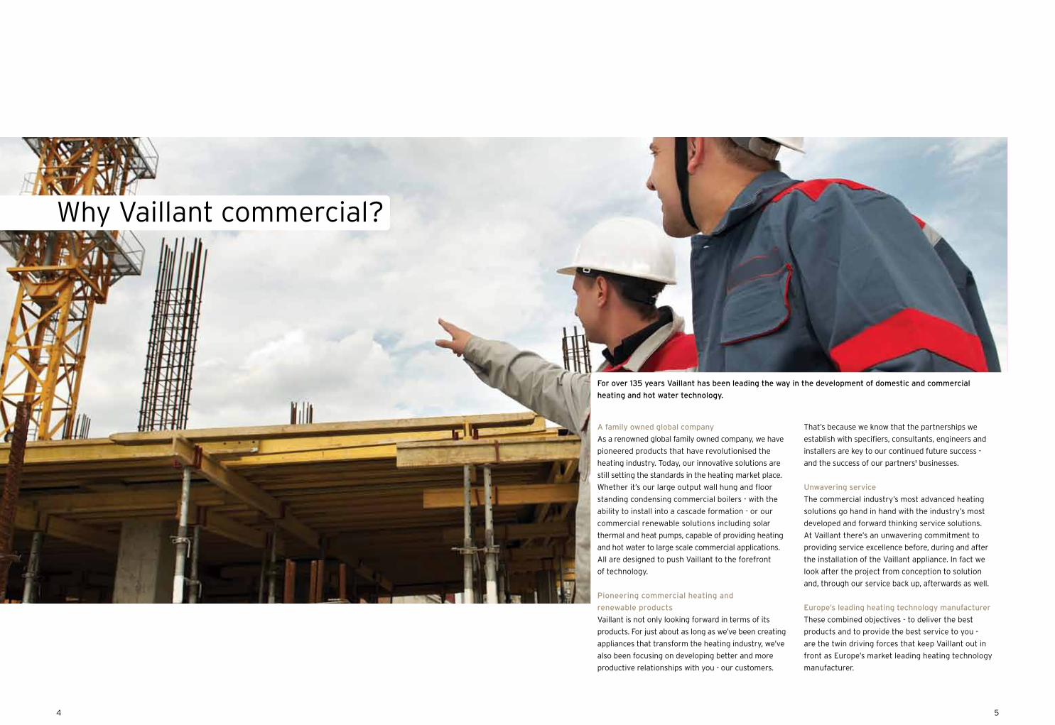
For over 135 years Vaillant has been leading the way in the development of domestic and commercial
heating and hot water technology.
54
Our training courses are designed for Gas Safe
Registered Installers, low carbon and renewable
technology installers, local authorities, housing
associations, architects, specifiers, merchants and
stockists. As the industry’s leading training provider,
we offer an all-encompassing range of courses on
domestic boilers, cylinders, solar domestic hot water
systems, air to air heat pumps, commercial boilers,
certification in energy efficiency, combustion analyser
assessment, ground source and air to water heat
pumps, domestic controls, mechanical ventilation
heat recovery and MCS Quality Management.
Training is provided in the main at six Vaillant
Centres of Excellence. These spacious state of the art
facilities offer a comfortable and superbly equipped
training environment, with plenty of opportunities
for hands-on experience and product familiarisation.
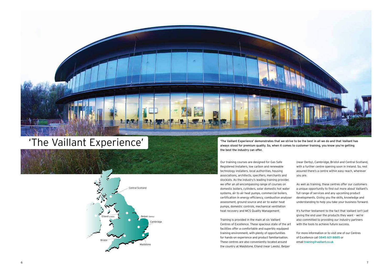
These centres are also conveniently located around
the country at Maidstone, Elland (near Leeds), Belper
(near Derby), Cambridge, Bristol and Central Scotland,
with a further centre opening soon in Ireland. So, rest
assured there’s a centre within easy reach, wherever
you are.
As well as training, these centres offer our customers
a unique opportunity to find out more about Vaillant’s
full range of services and any upcoming product
developments. Giving you the skills, knowledge and
understanding to help you take your business forward.
It’s further testament to the fact that Vaillant isn’t just
giving the end user the products they want – we’re
also committed to providing our industry partners
with the tools to achieve future success.
For more information or to visit one of our Centres
of Excellence call 0845 601 8885 or
email [email protected]
‘The Vaillant Experience’
Central Scotland
Elland (Leeds) Belper (Derby)
Cambridge
Bristol
Maidstone
76
‘The Vaillant Experience’ demonstrates that we strive to be the best in all we do and that Vaillant has
always stood for premium quality. So, when it comes to customer training, you know you’re getting
the best the industry can offer.
Service
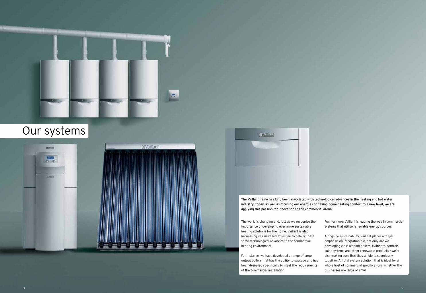
Our systems
98
The world is changing and, just as we recognise the
importance of developing ever more sustainable
heating solutions for the home, Vaillant is also
harnessing its unrivalled expertise to deliver these
same technological advances to the commercial
heating environment.
For instance, we have developed a range of large
output boilers that has the ability to cascade and has
been designed specifically to meet the requirements
of the commercial installation.
Furthermore, Vaillant is leading the way in commercial
systems that utilise renewable energy sources.
Alongside sustainability, Vaillant places a major
emphasis on integration. So, not only are we
developing class leading boilers, cylinders, controls,
solar systems and other renewable products – we’re
also making sure that they all blend seamlessly
together. A ‘total system solution’ that is ideal for a
whole host of commercial specifications, whether the
businesses are large or small.
The Vaillant name has long been associated with technological advances in the heating and hot water
industry. Today, as well as focusing our energies on taking home heating comfort to a new level, we are
applying this passion for innovation to the commercial arena.
1110
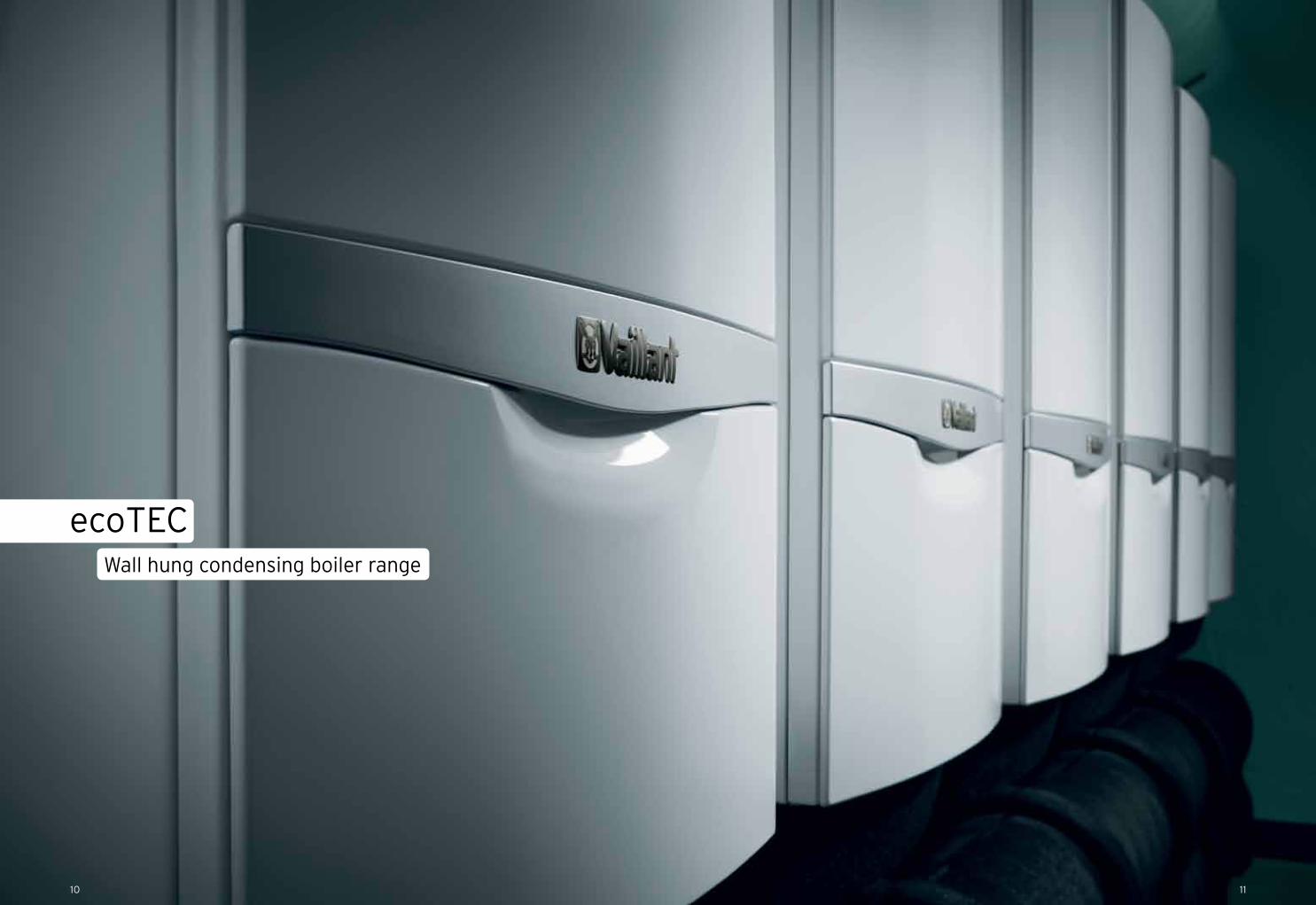
ecoTECWall hung condensing boiler range
ecoTEC 46 & 65
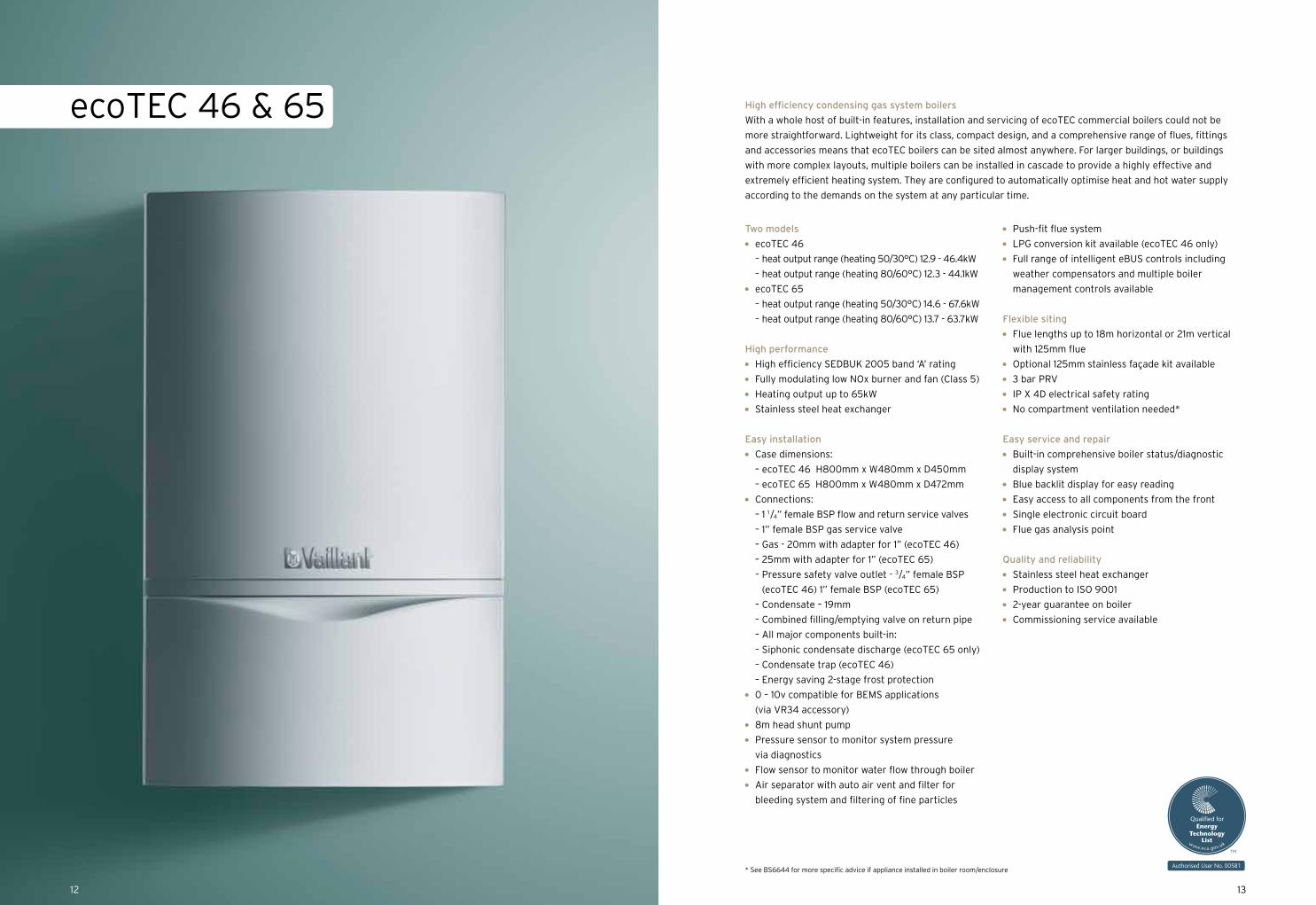
Two models
ecoTEC 46
– heat output range (heating 50/30°C) 12.9 - 46.4kW
– heat output range (heating 80/60°C) 12.3 - 44.1kW
ecoTEC 65
– heat output range (heating 50/30°C) 14.6 - 67.6kW
– heat output range (heating 80/60°C) 13.7 - 63.7kW
High performance
High efficiency SEDBUK 2005 band ‘A’ rating
Fully modulating low NOx burner and fan (Class 5)
Heating output up to 65kW
Stainless steel heat exchanger
Easy installation
Case dimensions:
– ecoTEC 46 H800mm x W480mm x D450mm
– ecoTEC 65 H800mm x W480mm x D472mm
Connections:
– 1 1 / 4” female BSP flow and return service valves
– 1” female BSP gas service valve
– Gas - 20mm with adapter for 1” (ecoTEC 46)
– 25mm with adapter for 1” (ecoTEC 65)
– Pressure safety valve outlet - 3 / 4” female BSP
(ecoTEC 46) 1” female BSP (ecoTEC 65)
– Condensate – 19mm
– Combined filling/emptying valve on return pipe
– All major components built-in:
– Siphonic condensate discharge (ecoTEC 65 only)
– Condensate trap (ecoTEC 46)
– Energy saving 2-stage frost protection
0 – 10v compatible for BEMS applications
(via VR34 accessory)
8m head shunt pump
Pressure sensor to monitor system pressure
via diagnostics
Flow sensor to monitor water flow through boiler
Air separator with auto air vent and filter for
bleeding system and filtering of fine particles
Push-fit flue system
LPG conversion kit available (ecoTEC 46 only)
Full range of intelligent eBUS controls including
weather compensators and multiple boiler
management controls available
Flexible siting
Flue lengths up to 18m horizontal or 21m vertical
with 125mm flue
Optional 125mm stainless façade kit available
3 bar PRV
IP X 4D electrical safety rating
No compartment ventilation needed*
Easy service and repair
Built-in comprehensive boiler status/diagnostic
display system
Blue backlit display for easy reading
Easy access to all components from the front
Single electronic circuit board
Flue gas analysis point
Quality and reliability
Stainless steel heat exchanger
Production to ISO 9001
2-year guarantee on boiler
Commissioning service available
High efficiency condensing gas system boilers
With a whole host of built-in features, installation and servicing of ecoTEC commercial boilers could not be
more straightforward. Lightweight for its class, compact design, and a comprehensive range of flues, fittings
and accessories means that ecoTEC boilers can be sited almost anywhere. For larger buildings, or buildings
with more complex layouts, multiple boilers can be installed in cascade to provide a highly effective and
extremely efficient heating system. They are configured to automatically optimise heat and hot water supply
according to the demands on the system at any particular time.
* See BS6644 for more specific advice if appliance installed in boiler room/enclosure
1312
1514
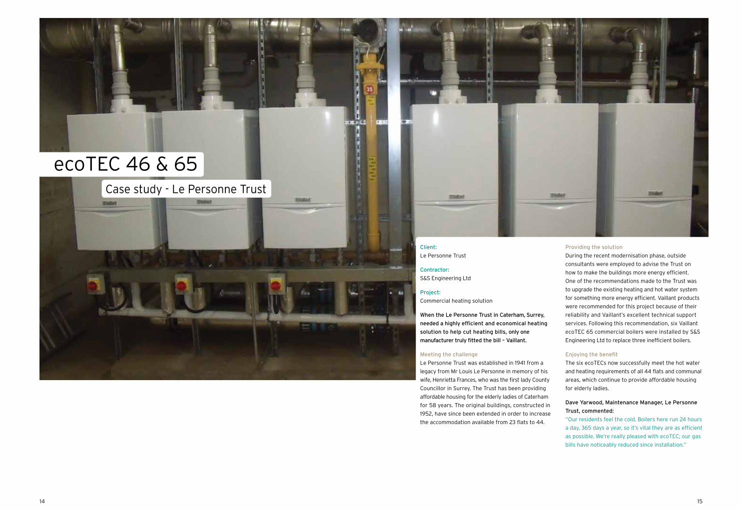
Client:
Le Personne Trust
Contractor:
S&S Engineering Ltd
Project:
Commercial heating solution
When the Le Personne Trust in Caterham, Surrey,
needed a highly efficient and economical heating
solution to help cut heating bills, only one
manufacturer truly fitted the bill – Vaillant.
Meeting the challenge
Le Personne Trust was established in 1941 from a
legacy from Mr Louis Le Personne in memory of his
wife, Henrietta Frances, who was the first lady County
Councillor in Surrey. The Trust has been providing
affordable housing for the elderly ladies of Caterham
for 58 years. The original buildings, constructed in
1952, have since been extended in order to increase
the accommodation available from 23 flats to 44.
Providing the solution
During the recent modernisation phase, outside
consultants were employed to advise the Trust on
how to make the buildings more energy efficient.
One of the recommendations made to the Trust was
to upgrade the existing heating and hot water system
for something more energy efficient. Vaillant products
were recommended for this project because of their
reliability and Vaillant’s excellent technical support
services. Following this recommendation, six Vaillant
ecoTEC 65 commercial boilers were installed by S&S
Engineering Ltd to replace three inefficient boilers.
Enjoying the benefit
The six ecoTECs now successfully meet the hot water
and heating requirements of all 44 flats and communal
areas, which continue to provide affordable housing
for elderly ladies.
Dave Yarwood, Maintenance Manager, Le Personne
Trust, commented:
“Our residents feel the cold. Boilers here run 24 hours
a day, 365 days a year, so it’s vital they are as efficient
as possible. We’re really pleased with ecoTEC; our gas
bills have noticeably reduced since installation.”
ecoTEC 46 & 65Case study - Le Personne Trust

ecoTEC 46 & 65
System design
1 2
3
14
78
9
8
10
1213
Variable temperature mixing circuit –HK2
Variable temperature direct circuit –HK1
Hot water circuit
VRC 470
VRC 693 outdoor sensor
15
VR 61/2 wiring centre VR 81/2
19
18
17
16
11 11
HK
2 ci
rcui
tm
ixin
g va
lve
BUS230 volt
E N L E N L E N L E N LE N
LP / ZP HK2-P
mai
ns in
put
conn
ecti
on
eBU
S
Low voltage terminals230 mains voltage terminals
Vaillant VR 61/2 Extension Module
VF2
2 1
HK2
open
cl
oseHK1-P
HK
1 cir
cuit
pum
p
HK
2 ci
rcui
tP
ump
HK
2 ci
rcui
tse
nsor
VRC edge connector X41
0FB
DC
FAF
RF 0 1 2 7 8 9- + L N E 3 4 5
L N E L N E
X6 X13
BUS 24 volt 230 volt
ecoTEC 466 & 656 / ecoCRAFT boiler terminals
safety circuit
boiler enable
230 mains voltage terminalsLow voltage terminals
VRC 693 outdoor sensor
VR
10 lo
w lo
ss
head
er s
enso
r
Hot water secondary circulation pump(set ecoTEC parameter d.26 to No 1)
Vaillant VR81
For use on HK2 set address to A2
Cyl
inde
r pr
imar
y pu
mp
LPor
sec
pum
p Z
P
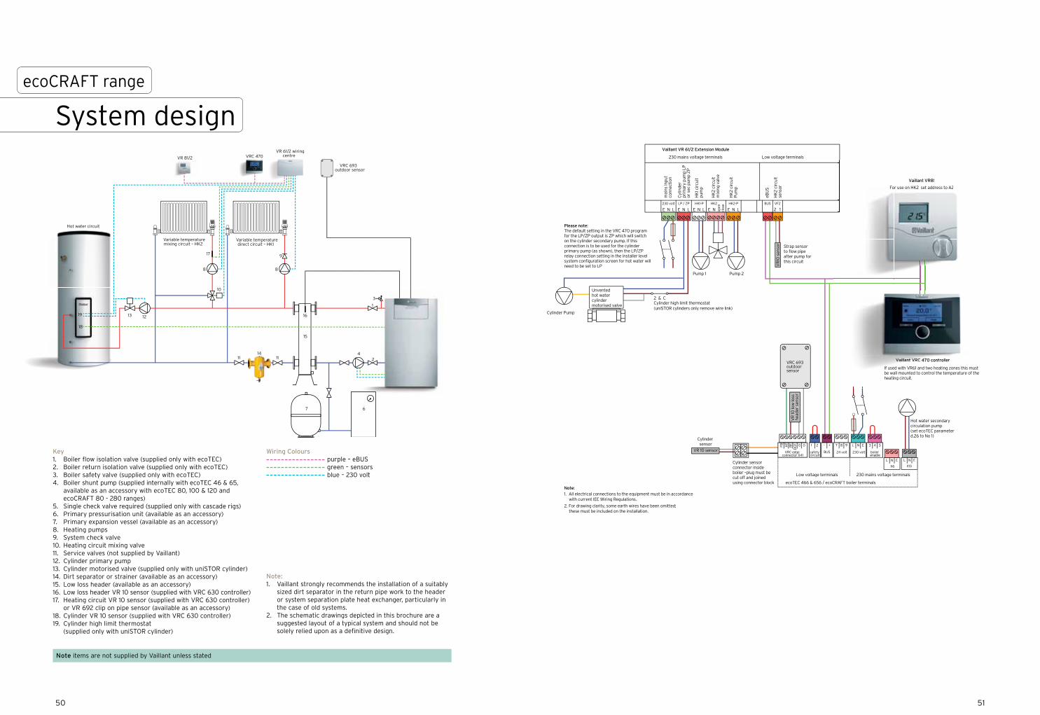
Please note:The default setting in the VRC 470 program for the LP/ZP output is ZP which will switch on the cylinder secondary pump. If this connection is to be used for the cylinder primary pump (as shown), then the LP/ZP relay connection setting in the installer level system configuration screen for hot water will need to be set to LP
Cylinder Pump
Cylinder sensor
Cylinder sensor connector inside boiler –plug must be cut off and joined using connector block
2 & CCylinder high limit thermostat(uniSTOR cylinders only remove wire link)
Pump 1 Pump 2
Vaillant VRC 470 controller
If used with VR61 and two heating zones this must be wall mounted to control the temperature of the heating circuit.
Strap sensor to flow pipe after pump for this circuit
Note:1. All electrical connections to the equipment must be in accordance with current IEE Wiring Regulations.
2. For drawing clarity, some earth wires have been omitted; these must be included on the installation.
VR 10 sensor
VR
10 s
enso
r
VailVailailVailVailllantantlantlant VVRC 470 controller
If used with VR61 and two heating zones this must be wall mounted to control the temperature of theheating circuit.
Unventedhot water cylinder motorised valve
Vaillant VR81
For use on HK2 set address to A2
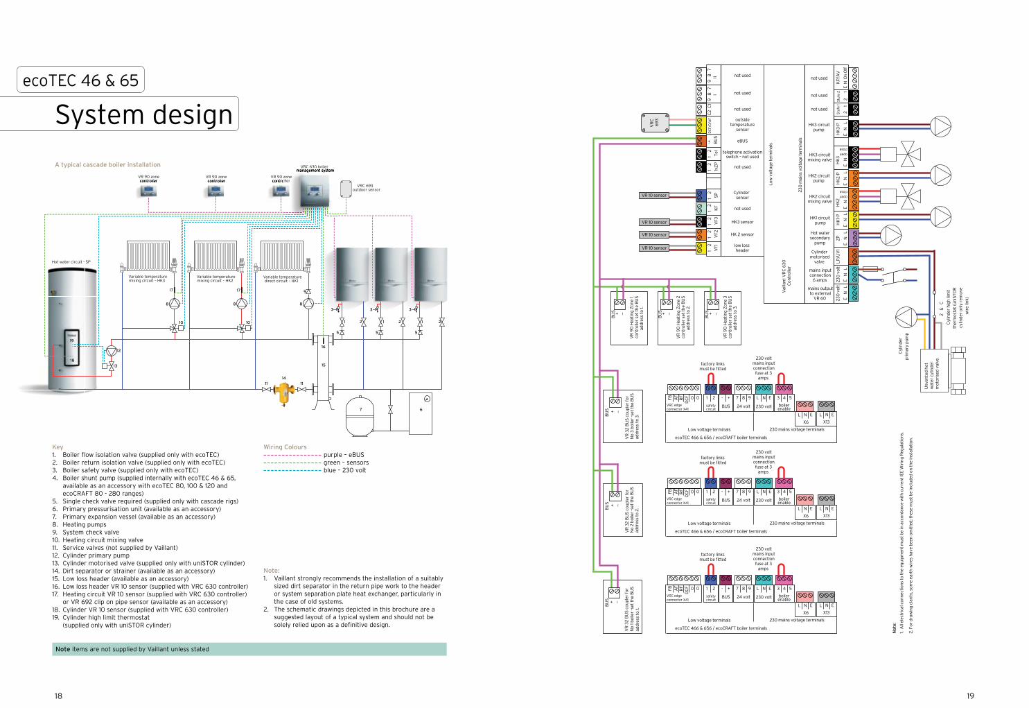
Key1. Boiler flow isolation valve (supplied only with ecoTEC)2. Boiler return isolation valve (supplied only with ecoTEC)3. Boiler safety valve (supplied only with ecoTEC)4. Boiler shunt pump (supplied internally with ecoTEC 46 & 65,
available as an accessory with ecoTEC 80, 100 & 120 and ecoCRAFT 80 - 280 ranges)
5. Single check valve required (supplied only with cascade rigs)6. Primary pressurisation unit (available as an accessory)7. Primary expansion vessel (available as an accessory)8. Heating pumps9. System check valve10. Heating circuit mixing valve11. Service valves (not supplied by Vaillant)12. Cylinder primary pump13. Cylinder motorised valve (supplied only with uniSTOR cylinder)14. Dirt separator or strainer (available as an accessory)15. Low loss header (available as an accessory)16. Low loss header VR 10 sensor (supplied with VRC 630 controller)17. Heating circuit VR 10 sensor (supplied with VRC 630 controller)
or VR 692 clip on pipe sensor (available as an accessory)18. Cylinder VR 10 sensor (supplied with VRC 630 controller)19. Cylinder high limit thermostat
(supplied only with uniSTOR cylinder)
Wiring Colours purple – eBUS green – sensors blue – 230 volt
Note items are not supplied by Vaillant unless stated
1716
A typical single boiler installation
Note:1. Vaillant strongly recommends the installation of a suitably
sized dirt separator in the return pipe work to the header or system separation plate heat exchanger, particularly in the case of old systems.
2. The schematic drawings depicted in this brochure are a suggested layout of a typical system and should not be solely relied upon as a definitive design.
1 1 22
3 3
55
14
7
8
6
9
3
1 2
5
15
Variable temperature mixing circuit – HK3
88
1010
1111
12
13
Variable temperature mixing circuit – HK2
Variable temperature direct circuit – HK1
Hot water circuit - SP
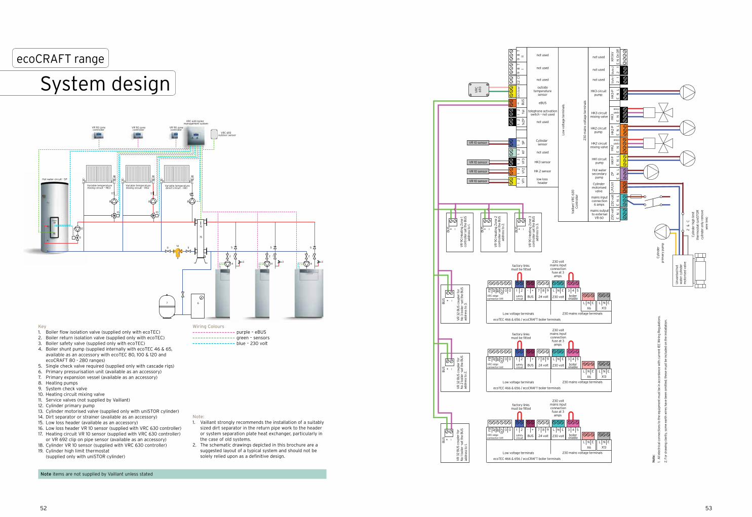
VR 90 zone controller
VR 90 zone controller
VRC 630 boiler management system
VRC 693 outdoor sensor
16
1717
18
19
VR 90 zone controller
VRC 630 boiler
zoneolleroller
System design
A typical cascade boiler installation
1918
ecoTEC 46 & 65
VR 10 sensor
VR 10 sensor
VR
32
BU
S c
oupl
er f
or
No
1 boi
ler
-set
the
BU
S
addr
ess
to 1.
VR 10 sensor
Unv
ente
d ho
t w
ater
cyl
inde
rm
otor
ised
val
ve
2 &
C
Cyl
inde
r hi
gh li
mit
th
erm
osta
t (u
niS
TO
R
cylin
der
only
rem
ove
wir
e lin
k)
BU
S + _
BU
S + _
VR
32
BU
S c
oupl
er f
or
No
2 bo
iler
-set
the
BU
S
addr
ess
to 2
.
Cyl
inde
r pr
imar
y pu
mp
230
vol
t
E
N
LE
N
L
E
N
LE
N
L
E
N
LE
N
L
E
N
230
vol
tLP
/UV
1Z
PH
K1-
PH
K2
HK
2-P
HK
3-P
KP
/AV
E N
On
Off
Stu
fe 1
2
1
Stu
fe 2
2
1
mains output to external
VR 60
mains input connection
6 amps
HK3 circuit pump
not used
not used
not used
1 2
VF1
1 2
VF2
1 2
VF3
1 2 KF
1 2 SP
1 2
1xZ
P
1 2 Tel
-+ BU
SD
CF/
0/A
FC
2 C
19
8
7
I9
8
7
II
low loss header
HK 2 sensor
HK3 sensor
not used
not used
telephone activationswitch – not used
eBUS
outsidetemperature
sensor
Low
vol
tage
ter
min
als
230
mai
ns v
olta
ge t
erm
inal
s
Vai
llant
VR
C 6
30C
ontr
olle
r
not used
not used
not used
open close
E
N
HK
3
open close
HK1 circuit pump
HK2 circuit pump
Cylinder sensor
Cylinder motorised
valve
Hot water secondary
pump
HK3 circuit mixing valve
HK2 circuit mixing valve
BU
S + _
VR
90
Hea
ting
Zon
e 1
cont
rolle
r se
t th
e B
US
ad
dres
s to
1.
BU
S + _
VR
90
Hea
ting
Zon
e 2
cont
rolle
r se
t th
e B
US
ad
dres
s to
2.
BU
S + _
VR
90
Hea
ting
Zon
e 3
cont
rolle
r se
t th
e B
US
ad
dres
s to
3.
VR 10 sensor
BU
S + _
VR
32
BU
S c
oupl
er f
or
No
3 bo
iler
-set
the
BU
S
addr
ess
to 3
.
Not
e:
1. A
ll el
ectr
ical
con
nect
ions
to
the
equi
pmen
t m
ust
be in
acc
orda
nce
wit
h cu
rren
t IE
E W
irin
g R
egul
atio
ns.
2. F
or d
raw
ing
clar
ity,
som
e ea
rth
wir
es h
ave
been
om
itte
d; t
hese
mus
t be
incl
uded
on
the
inst
alla
tion
.
230 volt mains input connection fuse at 3
amps
factory linksmust be fitted
VRC edge connector X41
0FB
DC
FAF
RF 0 1 2 7 8 9- + L N E 3 4 5
L N E L N E
X6 X13
BUS 24 volt 230 volt
ecoTEC 466 & 656 / ecoCRAFT boiler terminals
safety circuit
boiler enable
230 mains voltage terminalsLow voltage terminals
VR
C6
93
Key1. Boiler flow isolation valve (supplied only with ecoTEC)2. Boiler return isolation valve (supplied only with ecoTEC)3. Boiler safety valve (supplied only with ecoTEC)4. Boiler shunt pump (supplied internally with ecoTEC 46 & 65,
available as an accessory with ecoTEC 80, 100 & 120 and ecoCRAFT 80 - 280 ranges)
5. Single check valve required (supplied only with cascade rigs)6. Primary pressurisation unit (available as an accessory)7. Primary expansion vessel (available as an accessory)8. Heating pumps9. System check valve10. Heating circuit mixing valve11. Service valves (not supplied by Vaillant)12. Cylinder primary pump13. Cylinder motorised valve (supplied only with uniSTOR cylinder)14. Dirt separator or strainer (available as an accessory)15. Low loss header (available as an accessory)16. Low loss header VR 10 sensor (supplied with VRC 630 controller)17. Heating circuit VR 10 sensor (supplied with VRC 630 controller)
or VR 692 clip on pipe sensor (available as an accessory)18. Cylinder VR 10 sensor (supplied with VRC 630 controller)19. Cylinder high limit thermostat
(supplied only with uniSTOR cylinder)
Wiring Colours purple – eBUS green – sensors blue – 230 volt
Note items are not supplied by Vaillant unless stated
Note:1. Vaillant strongly recommends the installation of a suitably
sized dirt separator in the return pipe work to the header or system separation plate heat exchanger, particularly in the case of old systems.
2. The schematic drawings depicted in this brochure are a suggested layout of a typical system and should not be solely relied upon as a definitive design.
2120
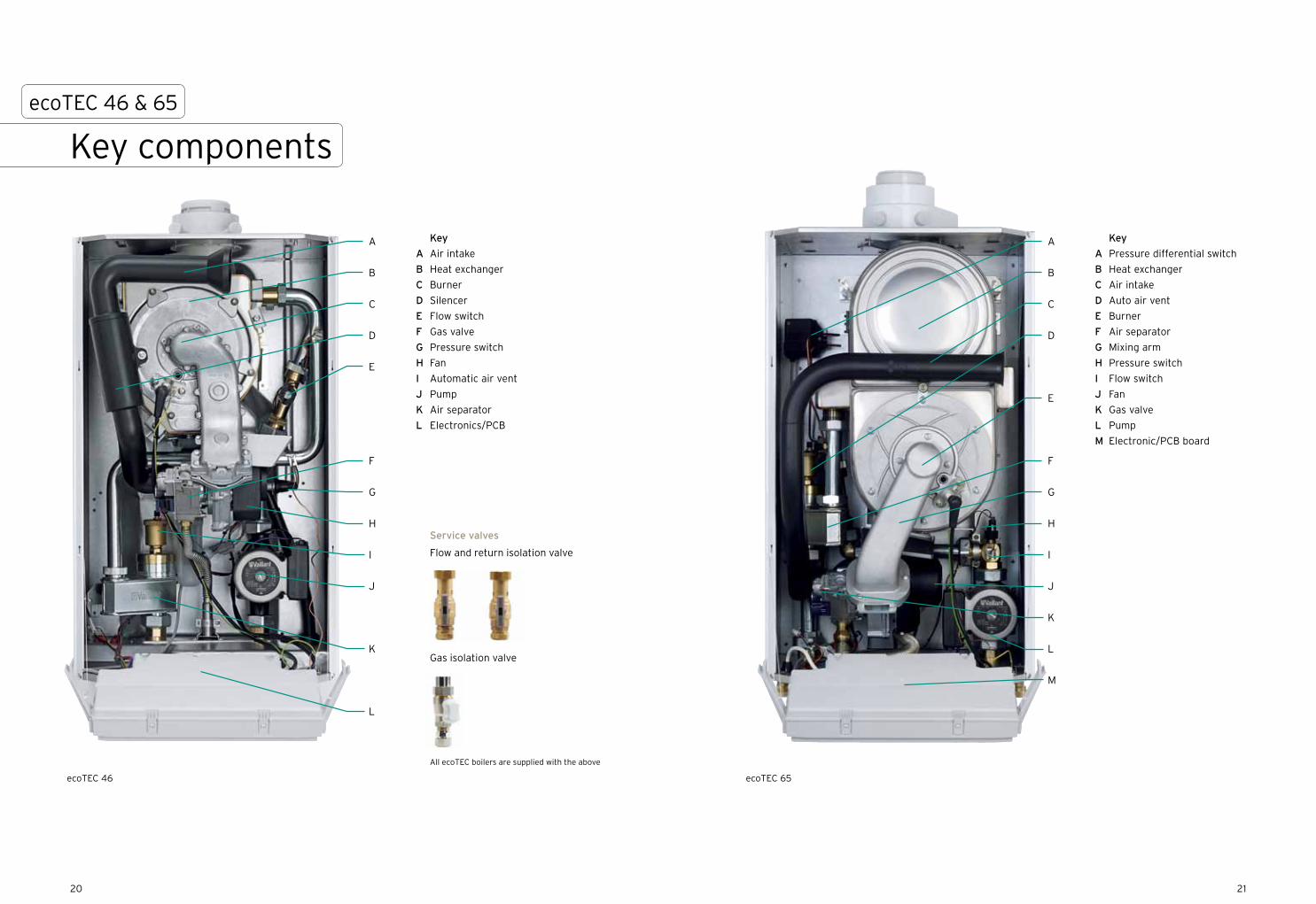
ecoTEC 46
A
B
C
D
E
F
G
H
I
J
K
L
Key
A Air intake
B Heat exchanger
C Burner
D Silencer
E Flow switch
F Gas valve
G Pressure switch
H Fan
I Automatic air vent
J Pump
K Air separator
L Electronics/PCB
Service valves
Flow and return isolation valve
Gas isolation valve
All ecoTEC boilers are supplied with the above
ecoTEC 65
A
B
C
D
E
F
G
H
I
J
K
L
M
Key
A Pressure differential switch
B Heat exchanger
C Air intake
D Auto air vent
E Burner
F Air separator
G Mixing arm
H Pressure switch
I Flow switch
J Fan
K Gas valve
L Pump
M Electronic/PCB board
Key componentsecoTEC 46 & 65
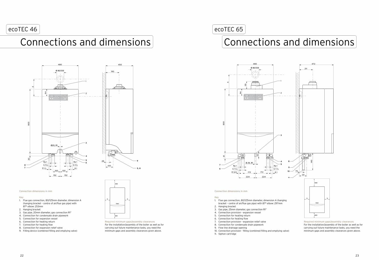
Connection dimensions in mm
Key1. Flue gas connection, 80/125mm diameter, dimension A (hanging
bracket – centre of air/flue gas pipe) with 87° elbow: 297mm2. Hanging bracket3. Gas pipe, 25mm diameter, gas connection R1”4. Connection provision - expansion vessel5. Connection for heating return6. Connection for heating flow7. Connection provision - expansion relief valve8. Connection for condensate drain pipework9. Flow line drainage opening10. Connection provision - filling (combined filling and emptying valve)11. Siphon cartridge
A
Ø 80/125
R 1100 100
152 152
100
48
190
80
03
0
49
Ø20, R1
G 11/2
1 pR1 pR
G 11/2
R 1/2
480 450
78
65
4
3
9
5, 8
1
2
Connection dimensions in mm
Key
1. Flue gas connection, 80/125 mm
diameter, dimension A (hanging bracket – centre of air/flue gas
pipe) with 87° elbow: 253 mm
2. Hanging bracket
3. gas pipe, 20 mm diameter, gas connection R1“
4. Connection for condensate drain pipework
5. Connection for expansion vessel
6. Connection for heating return
7. Connection for heating flow
8. Connection for expansion relief valve
9. Filling device (combined filling and emptying valve)
Required minimum gaps/assembly clearances
For the installation/assembly of the boiler as well as for
carrying out future maintenance tasks, you need the
minimum gaps and assembly clearances given below:
250
350
55
A
Ø 80/125
R 1172 172
32
224 224121
140
75
211
80
06
1
94
119
Ø 25, R1
G 1 1/2
1 pR1 pR
G 1 1/2
R 3/4
480 472
6
7 5
4
3
9
11
10
8
1
2
Connection dimensions in mm
Key1 Flue gas connection, 80/125 mm
diameter, dimension A (hanging bracket – centre of air/flue gas pipe) with 87° elbow: 297 mm
2 Hanging bracket3 Gas pipe, 25 mm diameter, gas connection R1“4 Connection provision - expansion vessel5 Connection for heating return6 Connection for heating flow7 Connection provision - expansion relief valve8 Connection for condensate drain pipework9 Flow line drainage opening10 Connection provision - filling (combined filling
and emptying valve)11 Siphon cartridge
Required minimum gaps/assembly clearances
For the installation/assembly of the boiler as well as for
carrying out future maintenance tasks, you need the
minimum gaps and assembly clearances given below:
400
500
5 5
Required minimum gaps/assembly clearancesFor the installation/assembly of the boiler as well as for carrying out future maintenance tasks, you need the minimum gaps and assembly clearances given above.
Required minimum gaps/assembly clearancesFor the installation/assembly of the boiler as well as for carrying out future maintenance tasks, you need the minimum gaps and assembly clearances given above.
2322
ecoTEC 46
Connections and dimensions
ecoTEC 65
Connections and dimensions
Connection dimensions in mm
Key1. Flue gas connection, 80/125mm diameter, dimension A
(hanging bracket – centre of air/flue gas pipe) with 87° elbow: 253mm
2. Hanging bracket3. Gas pipe, 20mm diameter, gas connection R1”4. Connection for condensate drain pipework5. Connection for expansion vessel6. Connection for heating return7. Connection for heating flow8. Connection for expansion relief valve9. Filling device (combined filling and emptying valve)

ecoTEC 46 65
Article number 0010004139 0010001440
Heat output range (heating 50/30°C) kW 12.9 - 46.4 14.6 - 67.6
Heat output range (heating 80/60°C) kW 12.3 - 44.1 13.7 - 63.7
Maximum heat input (net) kW 45 65
SEDBUK 2005 rating A A
SEDBUK 2009 annual efficiency % 89.1 88.7
Part L2 seasonal efficiency (natural gas) % 95.8 95.2
Part L2 seasonal efficiency (LPG) % 98.0 N/A
Net efficiency @ 100% load % 98.4 97.4
Net efficiency @ 30% load % 108.3 107.6
Inlet gas working pressure required (natural gas) mbar 20 20
Inlet gas working pressure required (LPG) mbar 37 N/A
NOx class 5 5
NOx levels mg/kWh 36 36
CO2 percentage (after 5 minutes full load +/- 1) % 8.8 8.8
Maximum CO level ppm 150 150
Gas rate (natural gas) m3/h 4.8 6.9
Gas rate (LPG) kg/h 3.5 N/A
Water flow rate (when ∆T = 20K) l/h 1935 2750
Available pump head (without check valve) mbar 280 280
Available pump head (with check valve) mbar 190 190
Pressure drop across the heat exchanger (at full load and 20K temperature difference)
mbar 350 375
Maximum flow temperature °C 85 85
Maximum operating primary pressure bar 3 3
Minimum operating primary pressure bar 0.8 0.8
Condensate volume (pH value: 3.0-4.0) l/h 4.5 6.5
Electrical connection V / Hz 230 / 50 230 / 50
Electrical power consumption min./max. (with integrated pump) W 138 / 180 170 / 260
Electrical protection rating - IP X 4 D IP X 4 D
Dimensions
Height mm 800 800
Width mm 480 480
Depth mm 450 472
Lift weight kg 46 75
Water content l 4.5 6.5
Flue
Flue gas mass flow min./max g/s 5.7 / 20.5 6.5 / 30.3
Flue gas temperature min./max. °C 40 / 70 40 / 70
Maximum length of concentric flue horizontal m 18 15
Maximum length of concentric flue vertical m 21 18
Connections
Heating flow/return (isolation valve size) 1 1⁄4” female BSP 1 1⁄4” female BSP
Gas isolation valve size 1” female BSP 1” female BSP
Pressure safety valve outlet 3⁄4” female BSP 1” female BSP
Condensate drain mm 19 19
Flue connection mm 80/125 80/125
ecoTEC 46 & 65
Technical specifications
2524

2726
Flue accessoriesecoTEC 46 & 65
ecoTEC
46 65
Max. permissible length of concentric flue
21.0m without elbow
18.0m without elbow
Maximum length of flue is reduced by 2.5m for each additional 870 elbow
Maximum length of flue is reduced by 1.0m for each additional 450 elbow
ecoTEC
46 65
Max. permissible length of concentric flue
18.0m plus 1 elbow, 870
15.0m plus 1 elbow, 870
Maximum length of flue is reduced by 2.5m for each additional 870 elbow
Maximum length of flue is reduced by 1.0m for each additional 450 elbow
Key
A Adjustable roof tile for
pitched roofs (009076)
B 87° elbow (303210)
C Flue extension pieces:
470mm extension (303202)
970mm extension (303203)
1970mm extension (303205)
D 45° elbow (2 of) (303211)
E Flue support clips -
pack of 5 (303616)
F Sliding sleeve (303215)
G Flat roof penetration
collar (009056)
H Vertical flue duct &
terminal (303200)
I Lead slate penetration seal
for pitched roofs (303980)
Key
A - D Horizontal flue terminal (303209)
A
A B
C
D
B
C
D
E
F
G
I
H
80/125mm concentric horizontal flue 80/125mm concentric vertical flue
I

ecoTEC commercial boilers can be used in cascade
configuration similar to that shown above. Each
boiler must be fitted with the flue gas non-return
valve accessory (303960). Please refer to the flue
installation manual (0020046373) for further help.
The non-return valve is not necessary if the chimney
is designed to EN 13384-2 and the natural draught is
greater than the pressure losses.
NoteFor non-standard flueing systems (e.g. chimneys with flexible liners and cascade flue system) advice from specialist flue companies must be sought. All flue installations must comply with the current Gas Safety (Installation and Use) regulations as well as current editions of BS5440-1, BS6644 and where necessary for installations over 150kW The Clean Air Act. Additionally any flue material must be suitable for the use and CE marked or comply with the current edition of BS715, also the flue system must be sized in accordance with EN13384-2 (chimneys - thermal and fluid dynamics calculation methods - Part 2: Chimneys serving more than one heating appliance).
ecoTEC 46 & 65
Cascade flueing
ecoTEC
VU GB 466/4-5 VU GB 656/4-5
Max. permissible length of concentric flue gas pipe
22.0m plus 3 elbows 870 and support elbow
22.0m plus 3 elbows 870 and support elbow
Air intake piece positioned no further than 4m from the connection with the boiler
AE
F
G
1 23 4 6
5
H
B
C
D
Key
A 45° elbow (pair of) (0020042757)
B 87° elbow (0020042756)
C Fixing bracket extension (0020042752)
D Rain collar for vertical roof penetrations
(0020042760)
E Flue extension pieces available in:
500mm extension (0020042753)
1m extension (0020042754)
500mm cutable extension (0020042755)
F Fixing bracket (0020042751)
G Fixing bracket (0020042751)
H Adjustable wall support for heights
in excess of 4m (0020042749)
Façade basic connection set (0020042748)
contains items:
1 - T-piece elbow
2 - Transition piece
3 - Inner wall rosette
4 - Outer wall rosette
5 - Wall penetration elbow
6 - Air intake piece
7 - Bird cage terminal
7
2928
80/125mm concentric stainless steel façade flue
80mm flue non-return valve
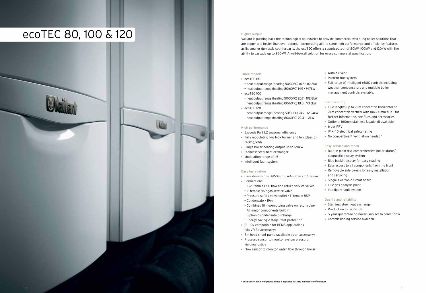
ecoTEC 80, 100 & 120
Three models
ecoTEC 80
– heat output range (heating 50/30°C) 16.5 - 82.3kW
– heat output range (heating 80/60°C) 14.9 - 74.7kW
ecoTEC 100
– heat output range (heating 50/30°C) 20.7 - 102.8kW
– heat output range (heating 80/60°C) 18.8 – 93.3kW
ecoTEC 120
– heat output range (heating 50/30°C) 24.7 - 123.4kW
– heat output range (heating 80/60°C) 22.4 - 112kW
High performance
Exceeds Part L2 seasonal efficiency
Fully modulating low NOx burner and fan (class 5)
<40mg/kWh
Single boiler heating output up to 120kW
Stainless steel heat exchanger
Modulation range of 1:5
Intelligent fault system
Easy installation
Case dimensions H960mm x W480mm x D602mm
Connections:
– 1 1⁄4” female BSP flow and return service valves
– 1” female BSP gas service valve
– Pressure safety valve outlet - 1” female BSP
– Condensate – 19mm
– Combined filling/emptying valve on return pipe
– All major components built-in:
– Siphonic condensate discharge
– Energy saving 2-stage frost protection
0 – 10v compatible for BEMS applications
(via VR 34 accessory)
8m head shunt pump (available as an accessory)
Pressure sensor to monitor system pressure
via diagnostics
Flow sensor to monitor water flow through boiler
Auto air vent
Push-fit flue system
Full range of intelligent eBUS controls including
weather compensators and multiple boiler
management controls available.
Flexible siting
Flue lengths up to 22m concentric horizontal or
24m concentric vertical with 110/160mm flue - for
further information, see flues and accessories
Optional 160mm stainless façade kit available
6 bar PRV
IP X 4D electrical safety rating
No compartment ventilation needed*
Easy service and repair
Built-in plain text comprehensive boiler status/
diagnostic display system
Blue backlit display for easy reading
Easy access to all components from the front
Removable side panels for easy installation
and servicing
Single electronic circuit board
Flue gas analysis point
Intelligent fault system
Quality and reliability
Stainless steel heat exchanger
Production to ISO 9001
5-year guarantee on boiler (subject to conditions)
Commissioning service available
* See BS6644 for more specific advice if appliance installed in boiler room/enclosure
31
* See BS6644 for more specific advice if appliance installed in boiler room/enclosure
Higher output
Vaillant is pushing back the technological boundaries to provide commercial wall hung boiler solutions that
are bigger and better than ever before. Incorporating all the same high performance and efficiency features
as its smaller domestic counterparts, the ecoTEC offers a superb output of 80kW, 100kW and 120kW with the
ability to cascade up to 960kW. A wall-to-wall solution for every commercial specification.
30
1 2
3
14
78
9
8
10
1213
Variable temperature mixing circuit –HK2
Variable temperature direct circuit –HK1
Hot water circuit
VRC 470
VRC 693 outdoor sensor
1 2
333
7
15
VR 61/2 wiring centre VR 81/2
19
18
17
16
11 11
3332
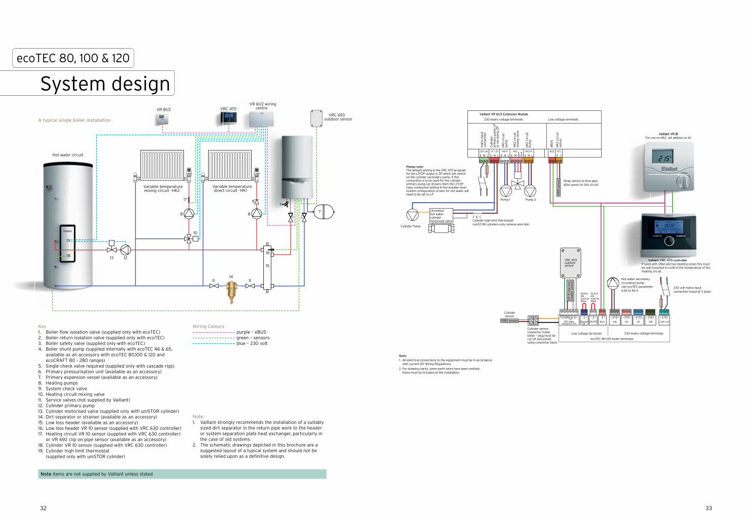
ecoTEC 80, 100 & 120
System design
A typical single boiler installation
VRC 693 outdoor sensor
Hot water secondary circulation pump (set ecoTEC parameter d.26 to No 1)
Please note:The default setting in the VRC 470 program for the LP/ZP output is ZP which will switch on the cylinder secondary pump. If this connection is to be used for the cylinder primary pump (as shown), then the LP/ZP relay connection setting in the installer level system configuration screen for hot water will need to be set to LP
Cylinder Pump
Cylinder sensor
Cylinder sensor connector inside boiler – plug must be cut off and joined using connector block
Unventedhot water cylinder motorised valve
Pump 1 Pump 2
Strap sensor to flow pipe after pump for this circuit
230 volt mains input connection fused at 3 amps
factory link must be fitted
factory link must be fitted
1 2 - + L N EL N EL N E
X13X16BUS 230 volt
ecoTEC 80-120 boiler terminals
Burner off
230 mains voltage terminalsLow voltage terminals
1 2
24V RT
L N E
X11
L N E
X18
HK
2 ci
rcui
tm
ixin
g va
lve
BUS230 volt
E N L E N L E N L E N LE NLP / ZP HK2-P
mai
ns in
put
conn
ecti
on
eBU
S
Low voltage terminals230 mains voltage terminals
Vaillant VR 61/2 Extension Module
VF2
2 1HK2
open
cl
oseHK1-P
HK
1 cir
cuit
pum
p
HK
2 ci
rcui
tP
ump
HK
2 ci
rcui
tse
nsor
Cyl
inde
r pr
imar
y pu
mp
LPor
sec
pum
p Z
P
Vaillant VR 81For use on HK2 set address to A2
Vaillant VR 81For use on HK2 set address to A2
Vaillant VRC 470 controllerIf used with VR61 and two heating zones this must be wall mounted to control the temperature of the heating circuit.
VR
10 s
enso
r
2 & CCylinder high limit thermostat(uniSTOR cylinders only remove wire link)
Note:1. All electrical connections to the equipment must be in accordance with current IEE Wiring Regulations.
2. For drawing clarity, some earth wires have been omitted; these must be included on the installation.
VR10 sensor VRC edge connector X41
0FB
DC
FAF
RF 0
VR
10 lo
w lo
ss
head
er s
enso
r
Hot water secondaryi l ti
VailVailVailVailll tlantlantantlanant VRVRCVRCVRCVRC 444470 controllerIfIf uIf used with VR61 and two heating zones this must be wall mounted to control the temperature of theheating circuit.
Note items are not supplied by Vaillant unless stated
Key1. Boiler flow isolation valve (supplied only with ecoTEC)2. Boiler return isolation valve (supplied only with ecoTEC)3. Boiler safety valve (supplied only with ecoTEC)4. Boiler shunt pump (supplied internally with ecoTEC 46 & 65,
available as an accessory with ecoTEC 80,100 & 120 and ecoCRAFT 80 - 280 ranges)
5. Single check valve required (supplied only with cascade rigs)6. Primary pressurisation unit (available as an accessory)7. Primary expansion vessel (available as an accessory)8. Heating pumps9. System check valve10. Heating circuit mixing valve11. Service valves (not supplied by Vaillant)12. Cylinder primary pump13. Cylinder motorised valve (supplied only with uniSTOR cylinder)14. Dirt separator or strainer (available as an accessory)15. Low loss header (available as an accessory)16. Low loss header VR 10 sensor (supplied with VRC 630 controller)17. Heating circuit VR 10 sensor (supplied with VRC 630 controller)
or VR 692 clip on pipe sensor (available as an accessory)18. Cylinder VR 10 sensor (supplied with VRC 630 controller)19. Cylinder high limit thermostat
(supplied only with uniSTOR cylinder)
Wiring Colours purple – eBUS green – sensors blue – 230 volt
Note:1. Vaillant strongly recommends the installation of a suitably
sized dirt separator in the return pipe work to the header or system separation plate heat exchanger, particularly in the case of old systems.
2. The schematic drawings depicted in this brochure are a suggested layout of a typical system and should not be solely relied upon as a definitive design.

1 1 22
3 3
55
14
7
8
6
9
3
1 2
5
15
Variable temperature mixing circuit – HK3
88
1010
1111
12
13
Variable temperature mixing circuit – HK2
Variable temperature direct circuit – HK1
Hot water circuit - SP
VR 90 zone controller
VR 90 zone controller
VRC 630 boiler management system
VRC 693 outdoor sensor
16
1717
18
19
VR 90 zone controller
VRC 630 boiler
zoneolleroller
1
3
12
3
1 22
3
System design
A typical cascade boiler installation
3534
ecoTEC 80, 100 & 120
BU
S + _
VR
32
BU
S c
oupl
er f
or
No
3 bo
iler
-set
the
BU
S
addr
ess
to 2
.
BU
S + _
VR
32
BU
S c
oupl
er f
or
No
3 bo
iler
-set
the
BU
S
addr
ess
to 1.
VR
C6
93
2 &
C
Cyl
inde
r hi
gh li
mit
th
erm
osta
t (u
niS
TO
R
cylin
der
only
rem
ove
wir
e lin
k)
Cyl
inde
r pr
imar
y pu
mp
230
vol
t23
0 v
olt
LP/U
V1
ZP
HK
1-P
HK
2-P
HK
3-P
KP
/AV
Stu
fe 1
Stu
fe 2
2
1
mains output to external
VR 60
mains input connection
6 amps
HK3 circuit pump
not used
not used
not used
1 2
VF1
1 2
VF2
1 2
VF3
1 2 KF
1 2 SP
1 2
1xZ
P
1 2 Tel
- +
BU
SC
2 C
19
8
7
9
8
7I
II
low loss header
HK 2 sensor
HK3 sensor
not used
not used
telephone activationswitch –not used
eBUS
outsidetemperature
sensor
Low
vol
tage
ter
min
als
230
mai
ns v
olta
ge t
erm
inal
s
Vai
llant
VR
C 6
30
Con
trol
ler
not used
not used
not used
HK1 circuit pump
HK2 circuit pump
Cylinder sensor
Cylinder motorised
valve
Hot water secondary
pump
HK3 circuit mixing valve
HK2 circuit mixing valve
BU
S+ _
VR
90
Hea
ting
Zon
e 1
cont
rolle
r se
t th
e B
US
ad
dres
s to
1.
BU
S+ _
VR
90
Hea
ting
Zon
e 2
cont
rolle
r se
t th
e B
US
ad
dres
s to
2. B
US
+ _
VR
90
Hea
ting
Zon
e 3
cont
rolle
r se
t th
e B
US
ad
dres
s to
3.
230 volt mains input connection fuse at 3 amps
factory linksmust be fitted
VRC edge connector X41
0FB
DC
FAF
RF 0 1 2 - + L N EL N EL N E
X13X16BUS 230 volt
ecoTEC 80-120 boiler terminals
Burneroff
230 mains voltage terminalsLow voltage terminals
1 2
24V RT
L N E
X11
L N E
X18
230 volt mains input connection fuse at 3 amps
factory linksmust be fitted
VRC edge connector X41
0FB
DC
FAF
RF 0 1 2 - + L N EL N EL N E
X13X16BUS 230 volt
ecoTEC 80-120 boiler terminals
Burneroff
230 mains voltage terminalsLow voltage terminals
1 2
24V RT
L N E
X11
L N E
X18
230 volt mains input connection fuse at 3 amps
factory linksmust be fitted
VRC edge connector X41
0FB
DC
FAF
RF 0 1 2 - + L N EL N EL N E
X13X16BUS 230 volt
ecoTEC 80-120 boiler terminals
Burneroff
230 mains voltage terminalsLow voltage terminals
1 2
24V RT
L N E
X11
L N E
X18
VR 10 sensor
VR 10 sensor
VR 10 sensor
VR 10 sensor
DC
F/0
/AF
E N
On
Off
2
1E
N
L
E
N
LE
N
L
E
N
LE
N
L
E
N
LE
N
L
E
N
HK
3
open close
E
N
HK
2
open close
BU
S + _
VR
32
BU
S c
oupl
er f
or
No
3 bo
iler
-set
the
BU
S
addr
ess
to 3
.
Not
e:
1. A
ll el
ectr
ical
con
nect
ions
to
the
equi
pmen
t m
ust
be in
acc
orda
nce
wit
h cu
rren
t IE
E W
irin
g R
egul
atio
ns.
2. F
or d
raw
ing
clar
ity,
som
e ea
rth
wir
es h
ave
been
om
itte
d; t
hese
mus
t be
incl
uded
on
the
inst
alla
tion
.
Unv
ente
dho
t w
ater
cy
linde
r
mot
oris
ed v
alve
Note items are not supplied by Vaillant unless stated
Key1. Boiler flow isolation valve (supplied only with ecoTEC)2. Boiler return isolation valve (supplied only with ecoTEC)3. Boiler safety valve (supplied only with ecoTEC)4. Boiler shunt pump (supplied internally with ecoTEC 46 & 65,
available as an accessory with ecoTEC 80, 100 & 120 and ecoCRAFT 80 - 280 ranges)
5. Single check valve required (supplied only with cascade rigs)6. Primary pressurisation unit (available as an accessory)7. Primary expansion vessel (available as an accessory)8. Heating pumps9. System check valve10. Heating circuit mixing valve11. Service valves (not supplied by Vaillant)12. Cylinder primary pump13. Cylinder motorised valve (supplied only with uniSTOR cylinder)14. Dirt separator or strainer (available as an accessory)15. Low loss header (available as an accessory)16. Low loss header VR 10 sensor (supplied with VRC 630 controller)17. Heating circuit VR 10 sensor (supplied with VRC 630 controller)
or VR 692 clip on pipe sensor (available as an accessory)18. Cylinder VR 10 sensor (supplied with VRC 630 controller)19. Cylinder high limit thermostat
(supplied only with uniSTOR cylinder)
Wiring Colours purple – eBUS green – sensors blue – 230 volt
Note:1. Vaillant strongly recommends the installation of a suitably
sized dirt separator in the return pipe work to the header or system separation plate heat exchanger, particularly in the case of old systems.
2. The schematic drawings depicted in this brochure are a suggested layout of a typical system and should not be solely relied upon as a definitive design.
A
B
C
D
E
F
G
H
I
J
K
L
M
N
O
A
B
C
D
E
F
G
H
I
J
K
L
M
N
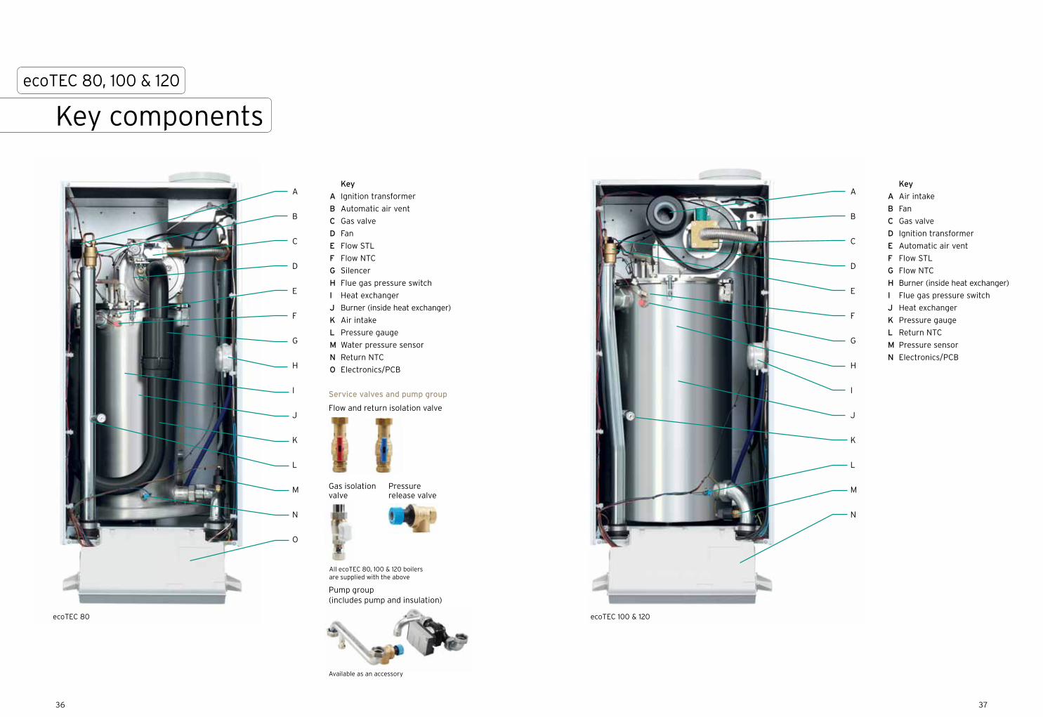
Key
A Ignition transformer
B Automatic air vent
C Gas valve
D Fan
E Flow STL
F Flow NTC
G Silencer
H Flue gas pressure switch
I Heat exchanger
J Burner (inside heat exchanger)
K Air intake
L Pressure gauge
M Water pressure sensor
N Return NTC
O Electronics/PCB
Key
A Air intake
B Fan
C Gas valve
D Ignition transformer
E Automatic air vent
F Flow STL
G Flow NTC
H Burner (inside heat exchanger)
I Flue gas pressure switch
J Heat exchanger
K Pressure gauge
L Return NTC
M Pressure sensor
N Electronics/PCB
Service valves and pump group
Pump group (includes pump and insulation)
Available as an accessory
3736
ecoTEC 100 & 120
Key components
ecoTEC 80, 100 & 120
ecoTEC 80
Flow and return isolation valve
Gas isolation valve
All ecoTEC 80, 100 & 120 boilers are supplied with the above
Pressure release valve
ecoTEC 80 100 120
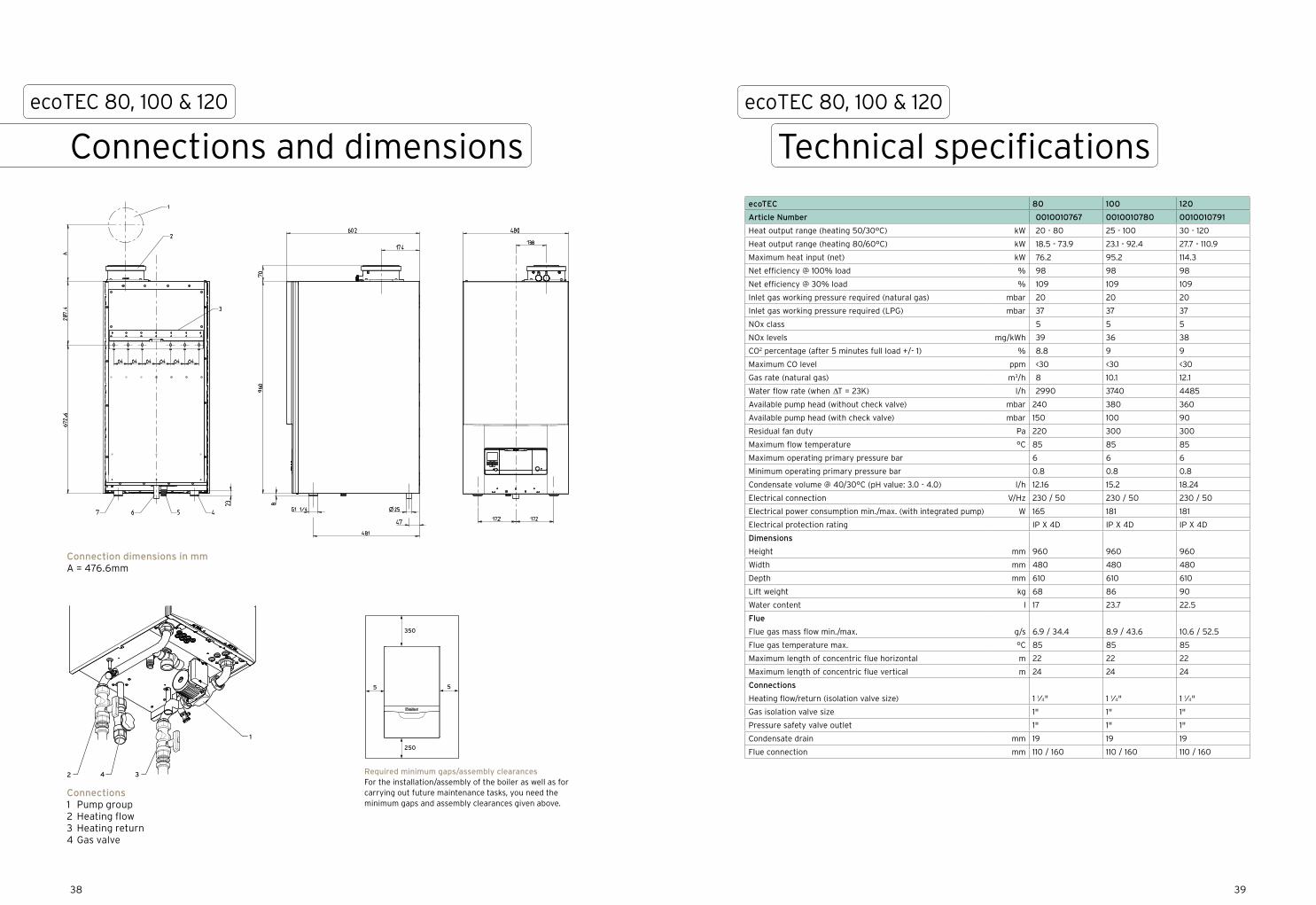
Article Number 0010010767 0010010780 0010010791
Heat output range (heating 50/30°C) kW 20 - 80 25 - 100 30 - 120
Heat output range (heating 80/60°C) kW 18.5 - 73.9 23.1 - 92.4 27.7 - 110.9
Maximum heat input (net) kW 76.2 95.2 114.3
Net efficiency @ 100% load % 98 98 98
Net efficiency @ 30% load % 109 109 109
Inlet gas working pressure required (natural gas) mbar 20 20 20
Inlet gas working pressure required (LPG) mbar 37 37 37
NOx class 5 5 5
NOx levels mg/kWh 39 36 38
CO2 percentage (after 5 minutes full load +/- 1) % 8.8 9 9
Maximum CO level ppm <30 <30 <30
Gas rate (natural gas) m3/h 8 10.1 12.1
Water flow rate (when ∆T = 23K) l/h 2990 3740 4485
Available pump head (without check valve) mbar 240 380 360
Available pump head (with check valve) mbar 150 100 90
Residual fan duty Pa 220 300 300
Maximum flow temperature °C 85 85 85
Maximum operating primary pressure bar 6 6 6
Minimum operating primary pressure bar 0.8 0.8 0.8
Condensate volume @ 40/30°C (pH value: 3.0 - 4.0) l/h 12.16 15.2 18.24
Electrical connection V/Hz 230 / 50 230 / 50 230 / 50
Electrical power consumption min./max. (with integrated pump) W 165 181 181
Electrical protection rating IP X 4D IP X 4D IP X 4D
Dimensions
Height mm 960 960 960
Width mm 480 480 480
Depth mm 610 610 610
Lift weight kg 68 86 90
Water content l 17 23.7 22.5
Flue
Flue gas mass flow min./max. g/s 6.9 / 34.4 8.9 / 43.6 10.6 / 52.5
Flue gas temperature max. °C 85 85 85
Maximum length of concentric flue horizontal m 22 22 22
Maximum length of concentric flue vertical m 24 24 24
Connections
Heating flow/return (isolation valve size) 1 1⁄4" 1 1⁄4" 1 1⁄4"
Gas isolation valve size 1" 1" 1"
Pressure safety valve outlet 1" 1" 1"
Condensate drain mm 19 19 19
Flue connection mm 110 / 160 110 / 160 110 / 160
39
Connections and dimensions
ecoTEC 80, 100 & 120
Technical specifications
ecoTEC 80, 100 & 120
1
4 32
Connection dimensions in mm A = 476.6mm
Connections1 Pump group2 Heating flow3 Heating return4 Gas valve
55
250
350
Required minimum gaps/assembly clearancesFor the installation/assembly of the boiler as well as for carrying out future maintenance tasks, you need the minimum gaps and assembly clearances given above.
38
4140
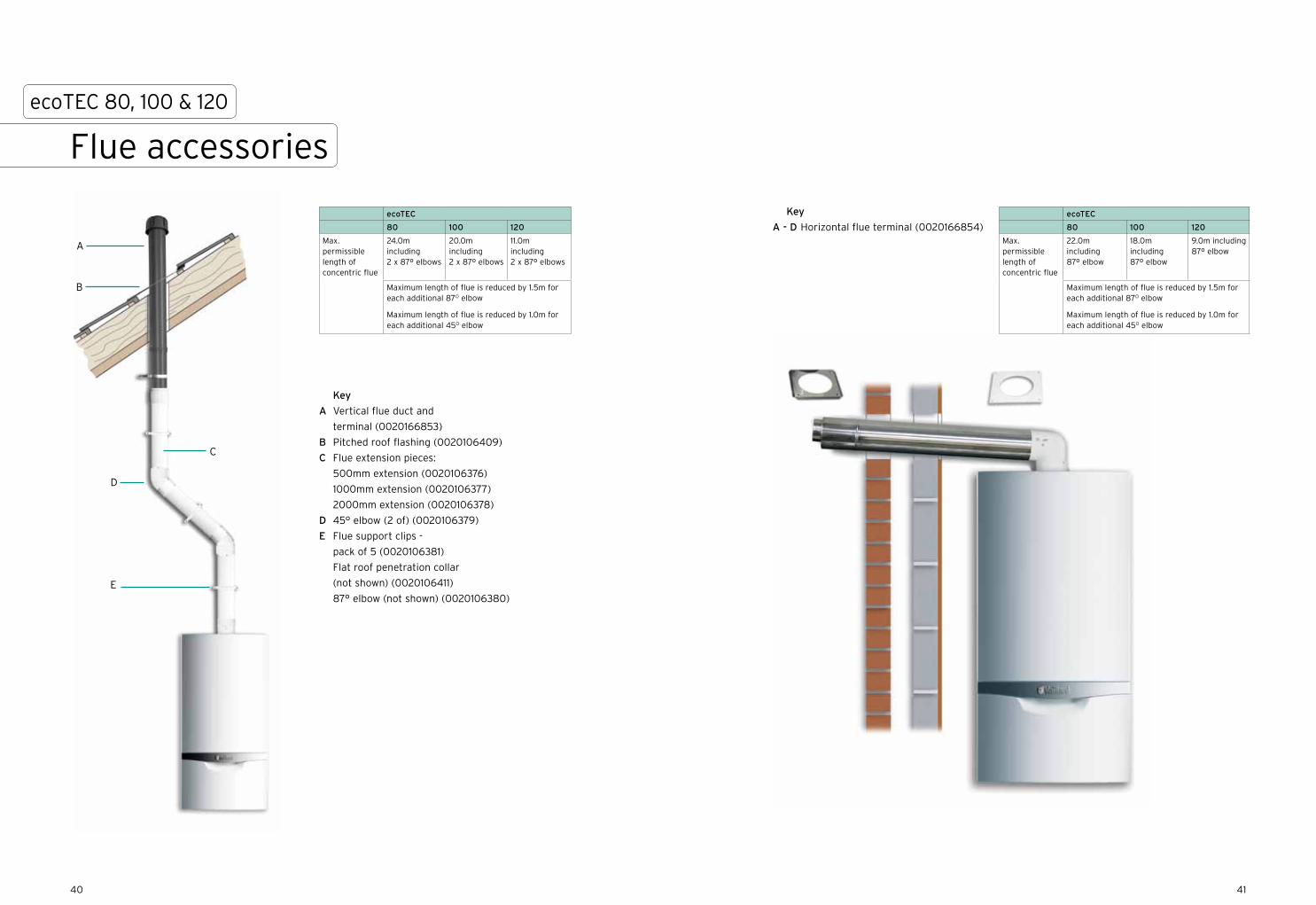
Flue accessories
ecoTEC 80, 100 & 120
ecoTEC
80 100 120
Max. permissible length of concentric flue
24.0m including 2 x 87º elbows
20.0m including 2 x 87º elbows
11.0m including 2 x 87º elbows
Maximum length of flue is reduced by 1.5m for each additional 87O elbow
Maximum length of flue is reduced by 1.0m for each additional 45O elbow
ecoTEC
80 100 120
Max. permissible length of concentric flue
22.0m including 87º elbow
18.0m including 87º elbow
9.0m including 87º elbow
Maximum length of flue is reduced by 1.5m for each additional 87O elbow
Maximum length of flue is reduced by 1.0m for each additional 45O elbow
Key
A Vertical flue duct and
terminal (0020166853)
B Pitched roof flashing (0020106409)
C Flue extension pieces:
500mm extension (0020106376)
1000mm extension (0020106377)
2000mm extension (0020106378)
D 45° elbow (2 of) (0020106379)
E Flue support clips -
pack of 5 (0020106381)
Flat roof penetration collar
(not shown) (0020106411)
87° elbow (not shown) (0020106380)
B
C
D
E
A
Key
A - D Horizontal flue terminal (0020166854)

Introducing the new Vaillant cascade rigs, to offer
even more efficiency and flexibility on outputs.
We are pleased to be able to offer our new range
of cascade rigging, which is an easily expandable
modular system and available for inline, back to back
and corner installations of up to six ecoTEC 46, 65,
80, 100 or 120 wall hung commercial boilers.
For more information, please see our commercial
website www.vaillant.co.uk/commercial or contact
your local Vaillant representative.
4342
Cascade rigsecoTEC 46, 65, 80, 100 & 120
4544
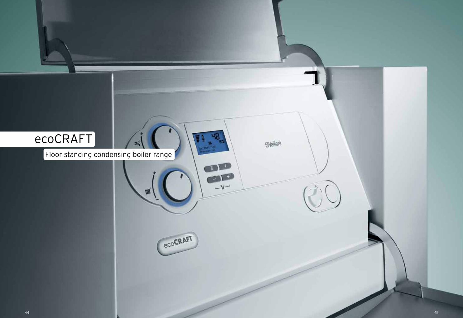
ecoCRAFTFloor standing condensing boiler range
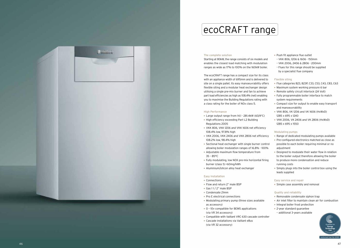
The complete solution
Starting at 80kW, the range consists of six models and
enables the closest load matching with modulation
ranges as wide as 17% to 100% on the 160kW boiler.
The ecoCRAFT range has a compact size for its class
with an appliance width of 695mm and is delivered to
site on a single pallet. Its easy manoeuvrability offers
flexible siting and a modular heat exchanger design
utilising a single pre-mix burner and fan to achieve
part load efficiencies as high as 108.4% (net) enabling
you to maximise the Building Regulations rating with
a class rating for the boiler of NOx class 5.
High Performance
Large output range from 14.1 - 281.4kW (60/40C)
High efficiency exceeding Part L2 Building
Regulations 2005
VKK 806, VKK 1206 and VKK 1606 net efficiency
108.4% low, 97.8% high
VKK 2006, VKK 2406 and VKK 2806 net efficiency
108.2% low, 98.4% high
Sectional heat exchanger with single burner control
allowing boiler modulation ranges of 16.8% - 100%
Adjustable maximum flow temperature from
35 – 85°C
Fully modulating, low NOX pre-mix horizontal firing
burner (class 5) <60mg/kWh
Aluminium/silicon alloy heat exchanger
Easy Installation
Connections
Flow and return 2” male BSP
Gas 1 1 / 2” male BSP
Condensate 21mm
Pro E electrical connections
Modulating primary pump (three sizes available
as accessory)
0 – 10v compatible for BEMS applications
(via VR 34 accessory)
Compatible with Vaillant VRC 630 cascade controller
Cascade installations via Vaillant eBus
(via VR 32 accessory)
Push fit appliance flue outlet
– VKK 806, 1206 & 1606 - 150mm
– VKK 2006, 2406 & 2806 - 200mm
– Flues for this range should be supplied
by a specialist flue company
Flexible siting
Flue categories B23, B23P, C33, C53, C43, C83, C63
Maximum system working pressure 6 bar
Remote safety circuit interlock (24 Volt)
Fully programmable boiler interface to match
system requirements
Compact size for output to enable easy transport
and manoeuvrability
VKK 806, VK 1206 and VK 1606 (HxWxD)
1285 x 695 x 1240
VKK 2006, VK 2406 and VK 2806 (HxWxD)
1285 x 695 x 1550
Modulating pumps
Range of dedicated modulating pumps available
Pre-configured electronics matched as close as
possible to each boiler requiring minimal or no
adjustment
Designed to modulate their water flow in relation
to the boiler output therefore allowing the boiler
to produce more condensation and reduce
running costs
Simply plugs into the boiler control box using the
leads supplied
Easy service and repair
Simple case assembly and removal
Quality and reliability
Removable condensate siphon trap
Air inlet filter to maintain clean air for combustion
Integral boiler frost protection
2-year standard guarantee
– additional 3-years available
4746
ecoCRAFT range

5554 4948
ecoCRAFT rangeCase study - St Mary’s School
Client:
St Mary’s School, Astley
Contractor:
Tudor (NW) Ltd
Project:
Commercial heating refurbishment
Tudor (NW) Ltd has successfully installed Vaillant
commercial boilers on a number of projects at different
locations over the years so we were confident to
put forward our products as first choice for the
refurbishment of St Mary’s Secondary School in
Astley, Manchester.
Meeting the challenge
St Mary’s is a very large voluntary aided Catholic
Secondary School built in the 1960s with approximately
1,600 pupils aged between 11 and 18. Due to the large
size of the school there are two plant rooms located
in the basement. Before the refurbishment took place,
these plant rooms housed a total of seven standard
efficiency boilers.
Providing the solution
The system was very old and had to be cleaned
thoroughly before any new boilers could be installed.
Eight ecoCRAFT high efficiency boilers were installed
between the two plant rooms; four with an output
of 240kW and four with an output of 280kW. As a
further precaution against dirt build up in the system, a
Spirotech SpiroCross combined low loss header/air and
dirt separator, was also supplied by Vaillant and installed.
Due to the added complication of the plant rooms
being located in a basement, the boilers had to be
lowered into it. This was made easier by the fact the
ecoCRAFT boiler casing unclips from the boiler frame,
which could then be used to fix the lifting gear.
Enjoying the benefit
The eight ecoCRAFTs now successfully meet the hot
water and heating requirements of the school.
Arthur Naylor, managing director of Tudor (NW) Ltd,
the installer responsible, commented:
“Complex projects require a trusted partner and
Vaillant is just that. Outstanding products backed up by
terrific pre and after-sales service give both my team
and our clients complete confidence of a flawless
install and reassurance of long term service.”
14
8
9
8
10
11
1213
Variable temperature mixing circuit – HK2
Variable temperature direct circuit – HK1
Hot water circuit
VRC 470
VRC 693 outdoor sensor
VR 61/2 wiring centre VR 81/2
19
18
17
1
4
7 6
2
15
16
3
11
5150
ecoCRAFT range
System design
HK
2 ci
rcui
tm
ixin
g va
lve
BUS230 volt
E N L E N L E N L E N LE N
LP / ZP HK2-P
mai
ns in
put
conn
ecti
on
eBU
S
Low voltage terminals230 mains voltage terminals
Vaillant VR 61/2 Extension Module
VF2
2 1
HK2
open
cl
oseHK1-P
HK
1 cir
cuit
pum
p
HK
2 ci
rcui
tP
ump
HK
2 ci
rcui
tse
nsor
VRC edge connector X41
0FB
DC
FAF
RF 0 1 2 7 8 9- + L N E 3 4 5
L N E L N E
X6 X13
BUS 24 volt 230 volt
ecoTEC 466 & 656 / ecoCRAFT boiler terminals
safety circuit
boiler enable
230 mains voltage terminalsLow voltage terminals
VRC 693 outdoor sensor
VR
10 lo
w lo
ss
head
er s
enso
r
Hot water secondary circulation pump(set ecoTEC parameter d.26 to No 1)
Vaillant VR81
For use on HK2 set address to A2
Cyl
inde
r pr
imar
y pu
mp
LPor
sec
pum
p Z
P
Please note:The default setting in the VRC 470 program for the LP/ZP output is ZP which will switch on the cylinder secondary pump. If this connection is to be used for the cylinder primary pump (as shown), then the LP/ZP relay connection setting in the installer level system configuration screen for hot water will need to be set to LP
Cylinder Pump
Cylinder sensor
Cylinder sensor connector inside boiler –plug must be cut off and joined using connector block
2 & CCylinder high limit thermostat(uniSTOR cylinders only remove wire link)
Pump 1 Pump 2
Vaillant VRC 470 controller
If used with VR61 and two heating zones this must be wall mounted to control the temperature of the heating circuit.
Strap sensor to flow pipe after pump for this circuit
Note:1. All electrical connections to the equipment must be in accordance with current IEE Wiring Regulations.
2. For drawing clarity, some earth wires have been omitted; these must be included on the installation.
VR 10 sensor
VR
10 s
enso
r
VailVailailVailVailllantantlantlant VVRC 470 controller
If used with VR61 and two heating zones this must be wall mounted to control the temperature of theheating circuit.
Unventedhot water cylinder motorised valve
Vaillant VR81
For use on HK2 set address to A2
Note items are not supplied by Vaillant unless stated
Key1. Boiler flow isolation valve (supplied only with ecoTEC)2. Boiler return isolation valve (supplied only with ecoTEC)3. Boiler safety valve (supplied only with ecoTEC)4. Boiler shunt pump (supplied internally with ecoTEC 46 & 65,
available as an accessory with ecoTEC 80, 100 & 120 and ecoCRAFT 80 - 280 ranges)
5. Single check valve required (supplied only with cascade rigs)6. Primary pressurisation unit (available as an accessory)7. Primary expansion vessel (available as an accessory)8. Heating pumps9. System check valve10. Heating circuit mixing valve11. Service valves (not supplied by Vaillant)12. Cylinder primary pump13. Cylinder motorised valve (supplied only with uniSTOR cylinder)14. Dirt separator or strainer (available as an accessory)15. Low loss header (available as an accessory)16. Low loss header VR 10 sensor (supplied with VRC 630 controller)17. Heating circuit VR 10 sensor (supplied with VRC 630 controller)
or VR 692 clip on pipe sensor (available as an accessory)18. Cylinder VR 10 sensor (supplied with VRC 630 controller)19. Cylinder high limit thermostat
(supplied only with uniSTOR cylinder)
Wiring Colours purple – eBUS green – sensors blue – 230 volt
Note:1. Vaillant strongly recommends the installation of a suitably
sized dirt separator in the return pipe work to the header or system separation plate heat exchanger, particularly in the case of old systems.
2. The schematic drawings depicted in this brochure are a suggested layout of a typical system and should not be solely relied upon as a definitive design.
5352
System designecoCRAFT range
1
4
14
7
8
9
2
15
Variable temperature mixing circuit – HK3
88
1010
1111
12
13
Variable temperature mixing circuit – HK2
Variable temperature direct circuit – HK1
Hot water circuit - SP
VR 90 zone controller
VR 90 zone controller
VR 90 zone controller
VRC 630 boiler management system
VRC 693 outdoor sensor
16
1717
18
19
3
1
4
2
3
1
4
2
3
6
5 55
VR 10 sensor
VR 10 sensor
VR
32
BU
S c
oupl
er f
or
No
1 boi
ler
-set
the
BU
S
addr
ess
to 1.
VR 10 sensor
Unv
ente
d ho
t w
ater
cyl
inde
rm
otor
ised
val
ve
2 &
C
Cyl
inde
r hi
gh li
mit
th
erm
osta
t (u
niS
TO
R
cylin
der
only
rem
ove
wir
e lin
k)
BU
S + _
BU
S + _
VR
32
BU
S c
oupl
er f
or
No
2 bo
iler
-set
the
BU
S
addr
ess
to 2
.
Cyl
inde
r pr
imar
y pu
mp
230
vol
t
E
N
LE
N
L
E
N
LE
N
L
E
N
LE
N
L
E
N
230
vol
tLP
/UV
1Z
PH
K1-
PH
K2
HK
2-P
HK
3-P
KP
/AV
E N
On
Off
Stu
fe 1
2
1
Stu
fe 2
2
1
mains output to external
VR 60
mains input connection
6 amps
HK3 circuit pump
not used
not used
not used
1 2
VF1
1 2
VF2
1 2
VF3
1 2 KF
1 2 SP
1 2
1xZ
P
1 2 Tel
-+ BU
SD
CF/
0/A
FC
2 C
19
8
7
I9
8
7
II
low loss header
HK 2 sensor
HK3 sensor
not used
not used
telephone activationswitch – not used
eBUS
outsidetemperature
sensor
Low
vol
tage
ter
min
als
230
mai
ns v
olta
ge t
erm
inal
s
Vai
llant
VR
C 6
30C
ontr
olle
r
not used
not used
not used
open close
E
N
HK
3
open close
HK1 circuit pump
HK2 circuit pump
Cylinder sensor
Cylinder motorised
valve
Hot water secondary
pump
HK3 circuit mixing valve
HK2 circuit mixing valve
BU
S + _
VR
90
Hea
ting
Zon
e 1
cont
rolle
r se
t th
e B
US
ad
dres
s to
1.
BU
S + _
VR
90
Hea
ting
Zon
e 2
cont
rolle
r se
t th
e B
US
ad
dres
s to
2.
BU
S + _
VR
90
Hea
ting
Zon
e 3
cont
rolle
r se
t th
e B
US
ad
dres
s to
3.
VR 10 sensor
BU
S + _
VR
32
BU
S c
oupl
er f
or
No
3 bo
iler
-set
the
BU
S
addr
ess
to 3
.
Not
e:
1. A
ll el
ectr
ical
con
nect
ions
to
the
equi
pmen
t m
ust
be in
acc
orda
nce
wit
h cu
rren
t IE
E W
irin
g R
egul
atio
ns.
2. F
or d
raw
ing
clar
ity,
som
e ea
rth
wir
es h
ave
been
om
itte
d; t
hese
mus
t be
incl
uded
on
the
inst
alla
tion
.
230 volt mains input connection fuse at 3
amps
factory linksmust be fitted
VRC edge connector X41
0FB
DC
FAF
RF 0 1 2 7 8 9- + L N E 3 4 5
L N E L N E
X6 X13
BUS 24 volt 230 volt
ecoTEC 466 & 656 / ecoCRAFT boiler terminals
safety circuit
boiler enable
230 mains voltage terminalsLow voltage terminals
230 volt mains input connection fuse at 3
amps
factory linksmust be fitted
VRC edge connector X41
0FB
DC
FAF
RF 0 1 2 7 8 9- + L N E 3 4 5
L N E L N E
X6 X13
BUS 24 volt 230 volt
ecoTEC 466 & 656 / ecoCRAFT boiler terminals
safety circuit
boiler enable
230 mains voltage terminalsLow voltage terminals
230 volt mains input connection fuse at 3
amps
factory linksmust be fitted
VRC edge connector X41
0FB
DC
FAF
RF 0 1 2 7 8 9- + L N E 3 4 5
L N E L N E
X6 X13
BUS 24 volt 230 volt
ecoTEC 466 & 656 / ecoCRAFT boiler terminals
safety circuit
boiler enable
230 mains voltage terminalsLow voltage terminals
VR
C6
93
Note items are not supplied by Vaillant unless stated
Key1. Boiler flow isolation valve (supplied only with ecoTEC)2. Boiler return isolation valve (supplied only with ecoTEC)3. Boiler safety valve (supplied only with ecoTEC)4. Boiler shunt pump (supplied internally with ecoTEC 46 & 65,
available as an accessory with ecoTEC 80, 100 & 120 and ecoCRAFT 80 - 280 ranges)
5. Single check valve required (supplied only with cascade rigs)6. Primary pressurisation unit (available as an accessory)7. Primary expansion vessel (available as an accessory)8. Heating pumps9. System check valve10. Heating circuit mixing valve11. Service valves (not supplied by Vaillant)12. Cylinder primary pump13. Cylinder motorised valve (supplied only with uniSTOR cylinder)14. Dirt separator or strainer (available as an accessory)15. Low loss header (available as an accessory)16. Low loss header VR 10 sensor (supplied with VRC 630 controller)17. Heating circuit VR 10 sensor (supplied with VRC 630 controller)
or VR 692 clip on pipe sensor (available as an accessory)18. Cylinder VR 10 sensor (supplied with VRC 630 controller)19. Cylinder high limit thermostat
(supplied only with uniSTOR cylinder)
Wiring Colours purple – eBUS green – sensors blue – 230 volt
Note:1. Vaillant strongly recommends the installation of a suitably
sized dirt separator in the return pipe work to the header or system separation plate heat exchanger, particularly in the case of old systems.
2. The schematic drawings depicted in this brochure are a suggested layout of a typical system and should not be solely relied upon as a definitive design.
5554
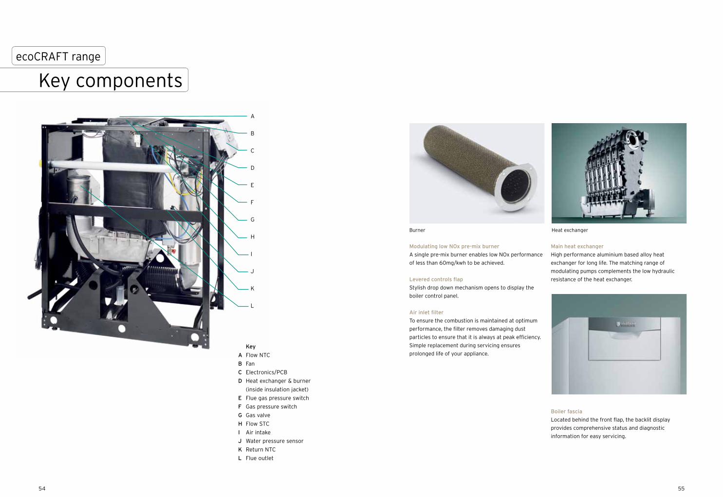
Modulating low NOx pre-mix burner
A single pre-mix burner enables low NOx performance
of less than 60mg/kwh to be achieved.
Levered controls flap
Stylish drop down mechanism opens to display the
boiler control panel.
Air inlet filter
To ensure the combustion is maintained at optimum
performance, the filter removes damaging dust
particles to ensure that it is always at peak efficiency.
Simple replacement during servicing ensures
prolonged life of your appliance.
Main heat exchanger
High performance aluminium based alloy heat
exchanger for long life. The matching range of
modulating pumps complements the low hydraulic
resistance of the heat exchanger.
Boiler fascia
Located behind the front flap, the backlit display
provides comprehensive status and diagnostic
information for easy servicing.
Heat exchangerBurner
Key componentsecoCRAFT range
A
B
C
D
E
F
G
H
I
J
K
L
Key
A Ignition transformer
B Automatic air vent
C Gas valve
D Fan
E Flow STL
F Flow NTC
G Silencer
H Gas flue pressure switch
I Heat exchanger
J Burner
K Air intake
L Pressure gauge
M Pressure sensor
N Return NTC
O Electronics/PCB
Key
A Flow NTC
B Fan
C Electronics/PCB
D Heat exchanger & burner
(inside insulation jacket)
E Flue gas pressure switch
F Gas pressure switch
G Gas valve
H Flow STC
I Air intake
J Water pressure sensor
K Return NTC
L Flue outlet
5756
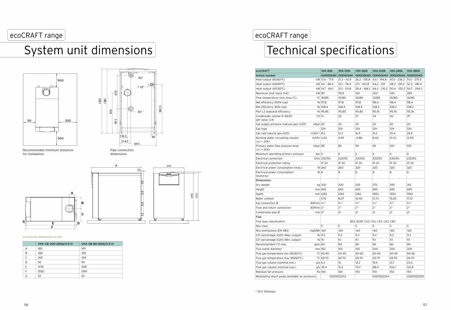
ecoCRAFT VKK 806 VKK 1206 VKK 1606 VKK 2006 VKK 2406 VKK 2806
Article number 0010005410 0010005411 0010005412 0010005413 0010005414 0010005415
Heat output (80/60°C) kW 13.6 - 77.9 21.3 - 112.9 26.2 - 155.8 43.1 - 196.8 47.0 - 236.2 51.0 - 275.5
Heat output (60/40°C) kW 14.1 - 80.4 22.1 - 116.5 27.1 - 160.8 44.2 - 201 48.2 - 241.2 52.3 - 281.4
Heat output (40/30°C) kW 14.7 - 84.1 23.1 - 121.8 28.4 - 168.2 46.2 - 210.2 50.4 - 252.2 54.7 - 294.3
Maximum heat input (net) kW 80 115.9 160 200 240 280
Flow temperature (min./max.°C) °C 35/85 35/85 35/85 35/85 35/85 35/85
Net efficiency 100% load % 97.8 97.8 97.8 98.4 98.4 98.4
Net efficiency 30% load % 108.4 108.4 108.4 108.2 108.2 108.2
Part L2 seasonal efficiency % 95.85 95.85 95.85 95.76 95.76 95.76
Condensate volume @ 40/30 (pH value: 3.4)
l/h 13 20 27 34 40 47
Gas supply pressure (natural gas) (G20) mbar 20 20 20 20 20 20
Gas type - 12H 12H 12H 12H 12H 12H
Gas rate natural gas (G20) m3/hr* 8.5 12.3 16.9 21.2 25.4 26.9
Nominal water circulating volume (∆ t = 20K)
m3/hr 3.44 4.99 6.88 8.60 10.33 12.05
Primary water flow pressure drop (∆ t = 20K)
mbar 80 85 90 95 100 105
Maximum operating primary pressure bar 6 6 6 6 6 6
Electrical connection V/Hz 230/50 230/50 230/50 230/50 230/50 230/50
Electrical protection rating - IP 20 IP 20 IP 20 IP 20 IP 20 IP 20
Electrical power consumption (max.) W 260 260 320 320 320 320
Electrical power consumption (stand-by)
W 8 8 8 8 8 8
Dimensions
Dry weight kg 200 200 235 275 295 310
Height mm 695 695 695 695 695 695
Depth mm 1240 1240 1240 1550 1550 1550
Water content l 5.74 8.07 10.40 12.73 15.05 17.37
Gas connection Ø BSP(m) 11⁄2” 11⁄2” 11⁄2” 11⁄2” 11⁄2” 11⁄2”
Flow and return connection BSP(m) 2” 2” 2” 2” 2” 2”
Condensate pipe Ø mm 21 21 21 21 21 21
Flue
Flue type classification B23, B23P, C33, C53, C43, C63, C83
Nox class 5 5 5 5 5 5
Nox emmissions (EN 483) mg/kWh <60 <60 <60 <60 <60 <60
CO2 percentage (G20) (Max. output) % 9.3 9.3 9.3 9.3 9.3 9.3
CO2 percentage (G20) (Min. output) % 9.1 9.1 9.1 9.1 9.1 9.1
Recommended CO2 max. ppm 80 80 80 80 80 80
Flue outlet diameter mm 150 150 150 200 200 200
Flue gas temperature min (80/600C) °C 60-65 60-65 60-65 60-65 60-65 60-65
Flue gas temperature max (80/600C) °C 65-70 65-70 65-70 65-70 65-70 65-70
Flue gas volume (nominal min.) g/s 6.3 10 12.2 19.9 21.7 23.5
Flue gas volume (nominal max.) g/s 35.4 51.2 70.7 88.4 106.1 123.8
Residual fan pressure Pa 100 100 150 150 150 150
Modulating shunt pump (available as accessory) 0020022253 0020022254 0020022255
* 15°C 1013mbar
128
5
F50
695
130
5
A
B
C
DEF
G
128
5
F50
695
130
5
A
B
C
DEF
G
128
5
F50
695
130
5
A
B
C
DEF
G
500
500
50 300
152,5
214,569 5
495
819
1285
1305
90
981,
5
678
R2‘‘
1 1/2“
R2‘ ‘
Recommended minimum distances for installation
Pipe connection dimensions
VKK GB 200-2806/3-E-H VKK GB 80-1606/3-E-H
A 165 165
B 326 326
C 369 369
D 50 50
E 1478 1168
F 1550 1240
G 22 22
System unit dimensionsecoCRAFT range
Technical specificationsecoCRAFT range
Connection dimensions in mm
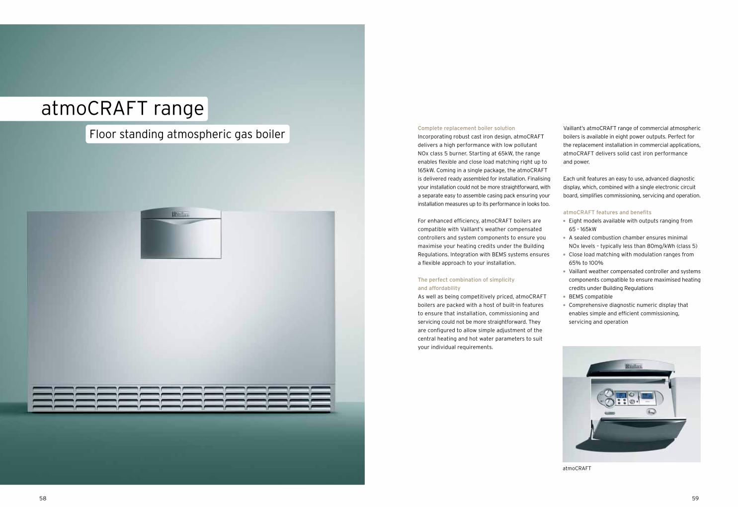
5958
atmoCRAFT
Complete replacement boiler solution
Incorporating robust cast iron design, atmoCRAFT
delivers a high performance with low pollutant
NOx class 5 burner. Starting at 65kW, the range
enables flexible and close load matching right up to
165kW. Coming in a single package, the atmoCRAFT
is delivered ready assembled for installation. Finalising
your installation could not be more straightforward, with
a separate easy to assemble casing pack ensuring your
installation measures up to its performance in looks too.
For enhanced efficiency, atmoCRAFT boilers are
compatible with Vaillant’s weather compensated
controllers and system components to ensure you
maximise your heating credits under the Building
Regulations. Integration with BEMS systems ensures
a flexible approach to your installation.
The perfect combination of simplicity
and affordability
As well as being competitively priced, atmoCRAFT
boilers are packed with a host of built-in features
to ensure that installation, commissioning and
servicing could not be more straightforward. They
are configured to allow simple adjustment of the
central heating and hot water parameters to suit
your individual requirements.
Vaillant’s atmoCRAFT range of commercial atmospheric
boilers is available in eight power outputs. Perfect for
the replacement installation in commercial applications,
atmoCRAFT delivers solid cast iron performance
and power.
Each unit features an easy to use, advanced diagnostic
display, which, combined with a single electronic circuit
board, simplifies commissioning, servicing and operation.
atmoCRAFT features and benefits
Eight models available with outputs ranging from
65 - 165kW
A sealed combustion chamber ensures minimal
NOx levels – typically less than 80mg/kWh (class 5)
Close load matching with modulation ranges from
65% to 100%
Vaillant weather compensated controller and systems
components compatible to ensure maximised heating
credits under Building Regulations
BEMS compatible
Comprehensive diagnostic numeric display that
enables simple and efficient commissioning,
servicing and operation
Floor standing atmospheric gas boiler
atmoCRAFT range

1
14
8
6
5
2
Variable temperature mixing circuit
88
1010
11
12
13
Variable temperature mixing circuit
Constant temperature circuit
Hot water circuit
3
7
11
1
14
7
8
5
15
Variable temperatureMixing circuit
88
1010
1111
12
13
Variable temperatureMixing circuit
Constant temperature circuit
Hot water circuit
6
5
4
2
3
5
3
2 1
4
6160
Note items are not supplied by Vaillant unless stated
Key1. Boiler flow isolation valve (supplied only with ecoTEC)2. Boiler return isolation valve (supplied only with ecoTEC)3. Boiler safety valve (supplied only with ecoTEC)4. Boiler shunt pump5. Non-return valve6. Primary pressurisation unit (available as an accessory)7. Primary expansion vessel (available as an accessory)8. Heating pumps10. Heating circuit mixing valve11. Service valves (not supplied by Vaillant)12. Cylinder primary pump13. Cylinder motorised valve (supplied only with
uniSTOR cylinder)14. Dirt separator or strainer (available as an accessory)15. Low loss header
atmoCRAFT range
System design
atmoCRAFT range
Key components
Heat exchanger
Cast iron sectional design heat exchanger delivered
fully assembled as a single unit for quick and simple
installation. The heat exchanger can be dismantled on
site for easier siting of boiler, and then re-assembled
using new boiler nipples and sealant. Vaillant provides
a boiler assembly tool hire service (please contact
Vaillant for more details).
Heat exchanger insulation
A heavy duty insulation covers the heat exchanger
improving overall thermal efficiency and reduces
standing heat losses.
Low NOx burner
Atmospheric burner designed to produce NOx levels
<80mg/kWh (class 5).
Automatic flue damper
Adjustment of the excess air being drawn through the
heat exchanger to the flue system, whilst the burner
is in low fire, will maintain a greater efficiency. Whilst
in stand-by mode the flue damper will remain in the
closed position thereby reducing the standing losses
of the appliance.
Sealed combustion chamber
The burner utilises a sealed combustion chamber
enabling only primary combustion air to burn with
the gas. This ensures the NOx levels are kept to an
absolute minimum.
Shunt pump
To prevent back end corrosion of the heat exchanger,
a shunt pump and thermostat are recommended.
Vaillant dedicated pumps and thermostats are
available as accessories.
Controls
atmoCRAFT boilers can be controlled with the
optional VRC 410s weather compensator to maximise
system and boiler efficiency.
The digital display unit can be wall-mounted and
automatically matches the boiler flow temperature
to the outside temperature.Note:1. Vaillant strongly recommends the installation of a suitably
sized dirt separator in the return pipe work to the header or system separation plate heat exchanger, particularly in the case of old systems.
2. The schematic drawings depicted in this brochure are a suggested layout of a typical system and should not be solely relied upon as a definitive design.

6362
Boiler type a b c ø d Heating feed/Heating return Gas connection
65kW 850mm 860mm 960mm 180mm 11⁄2” male BSP 1“ male BSP
75kW 930mm 850mm 960mm 200mm 11⁄2” male BSP 1“ male BSP
85kW 1010mm 850mm 960mm 200mm 11⁄2” male BSP 1“ male BSP
105kW 1170mm 838mm 960mm 225mm 11⁄2” male BSP 1“ male BSP
115kW 1250mm 838mm 960mm 225mm 11⁄2” male BSP 1“ male BSP
130kW 1410mm 825mm 960mm 250mm 11⁄2” male BSP 11⁄4” male BSP
150kW 1570mm 825mm 960mm 250mm 11⁄2” male BSP 11⁄4” male BSP
165kW 1730mm 852mm 1012mm 300mm 11⁄2” male BSP 11⁄4” male BSP
Key:1 Heating flow2 Gas connection3 Heating return4 Flue gas connection
atmoCRAFT VK 654 VK 754 VK 854 VK 1054 VK 1154 VK 1304 VK 1504 VK 1654
Article number 301928 301929 301930 301931 301932 301933 301934 301935
Heat output (80/60°C) kW 42.2 - 65 48.7 - 75 55.2 - 85 68.2 - 105 74.7 - 115 84.5 - 130 97.5 - 150 107.5 165
Maximum heat input (net) kW 70.7 81.5 92.5 114 125 141.3 163 179.3
Number of sections 8 9 10 12 13 15 17 19
Net efficiency 100% load % 91.23 91.33 90.91 91.21 91.14 91.28 91.41 91.51
Net efficiency 30% load % 91.56 91.46 91.01 91.41 90.98 90.68 90.84 90.94
Modulation range % 65-100
Flow temperature (max./min.) °C 35/83
Inlet gas working pressure
required (natural gas)
mbar 20
Inlet gas working pressure
required (LPG propane)
mbar 37
NOx class 5
NOx emissions mg/kWh <80
CO2 percentage
(after 5mins full load +/-1)
6.5 6.5 6.5 6.5 6.6 6.6 6.6 6.6
Flue type classification B11
Gas type II2H3P
Gas rate natural gas (G20) m3/h 7.4 8.5 9.7 11.9 13.0 14.9 17.0 18.8
Gas rate lpg propane (G31) kg/hr 5.5 6.3 7.2 8.8 9.7 11.0 12.7 14.0
Primary water flow pressure drop
(∆T = 20K) mbar 18 25 32 44 46 52 60 68
Primary water flow pressure drop
76 110 130 150 180 220 250 280(∆T = 10K) mbar
Maximum operating
primary pressure
bar 3
Electrical connection V/Hz 230/50
Electrical power consumption W <60
Dimensions
1145 1145 1145 1145 1145 1145 1145 1145Height mm
Width mm 850 930 1010 1170 1250 1410 1570 1730
Depth mm 960 960 960 960 960 960 960 1012
Dry weight kg 317 343 369 421 447 499 550 601
Water content l 28.0 31.0 34.3 40.9 44.0 51.0 57.0 65.0
Gas connection BSP(m) 1” 1” 1” 1” 1” 11/4” 11/4” 11/4”
Flow and return connection BSP(m) 11/2” 11/2” 11/2” 11/2” 11/2” 11/2” 11/2” 11/2”
Flue
180 200 200 225 225 250 225 300Flue outlet diameter (mm)
Flue gas temperature (min./max.) °C 80/115 80/115 80/115 80/115 80/115 80/115 80/115 80/115
Flue gas volume (nominal) kg/h 162 180 205 252 270 317 360 403
atmoCRAFT range
Technical specifications Unit dimensions
atmoCRAFT range
Connection dimensions in mm
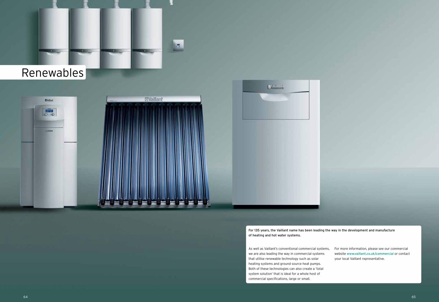
Renewables
As well as Vaillant’s conventional commercial systems,
we are also leading the way in commercial systems
that utilise renewable technology such as solar
heating systems and ground source heat pumps.
Both of these technologies can also create a ‘total
system solution’ that is ideal for a whole host of
commercial specifications, large or small.
For more information, please see our commercial
website www.vaillant.co.uk/commercial or contact
your local Vaillant representative.
For 135 years, the Vaillant name has been leading the way in the development and manufacture
of heating and hot water systems.
6564
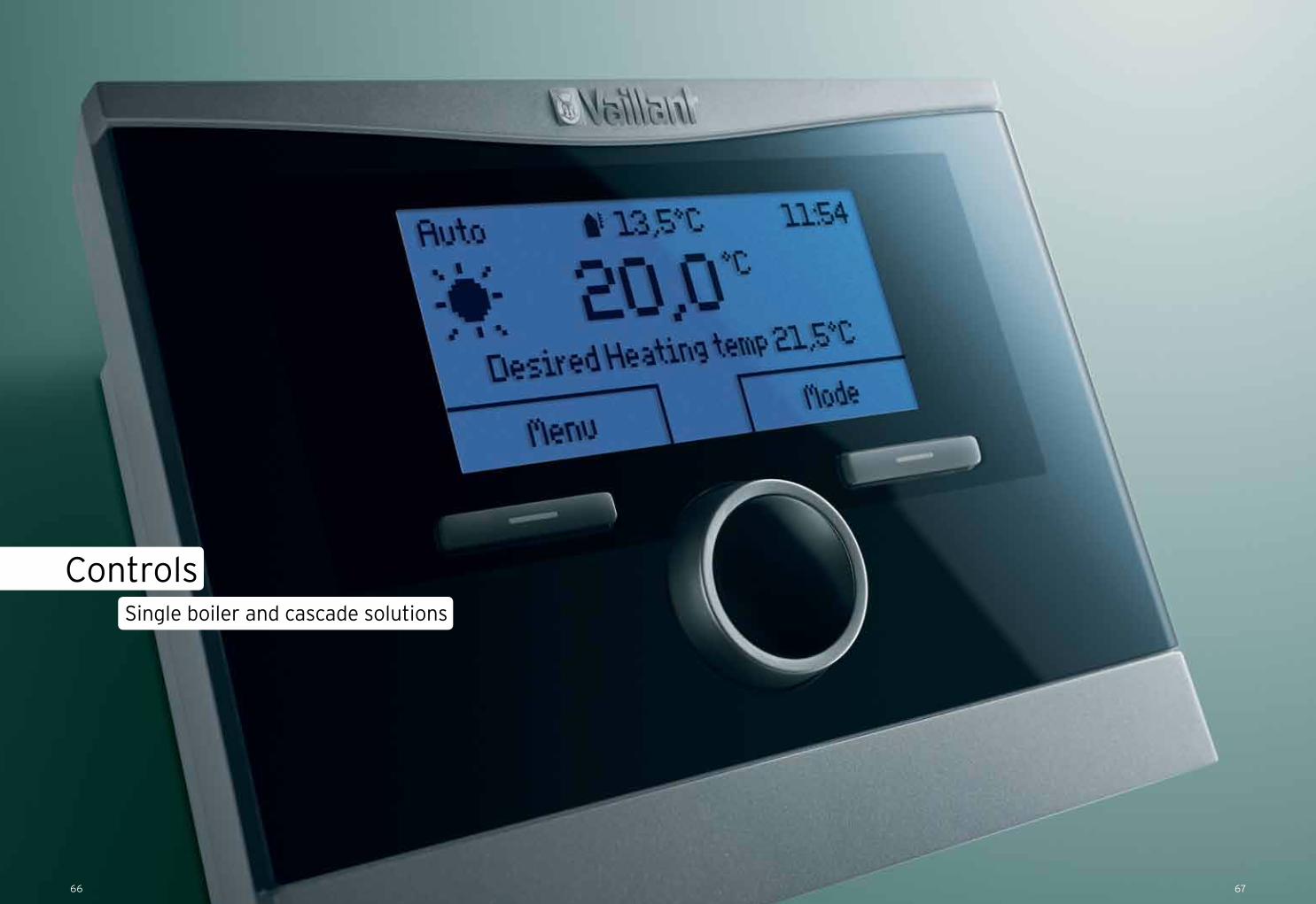
Controls
6766
Single boiler and cascade solutions
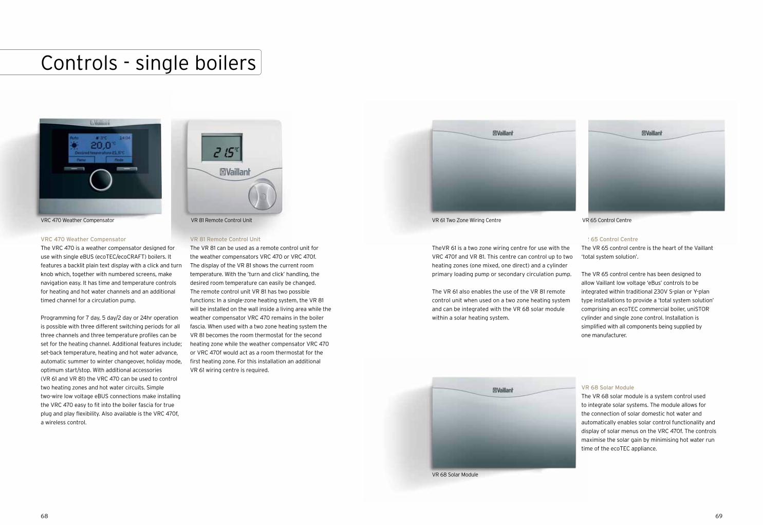
6968
VRC 470 Weather Compensator
The VRC 470 is a weather compensator designed for
use with single eBUS (ecoTEC/ecoCRAFT) boilers. It
features a backlit plain text display with a click and turn
knob which, together with numbered screens, make
navigation easy. It has time and temperature controls
for heating and hot water channels and an additional
timed channel for a circulation pump.
Programming for 7 day, 5 day/2 day or 24hr operation
is possible with three different switching periods for all
three channels and three temperature profiles can be
set for the heating channel. Additional features include;
set-back temperature, heating and hot water advance,
automatic summer to winter changeover, holiday mode,
optimum start/stop. With additional accessories
(VR 61 and VR 81) the VRC 470 can be used to control
two heating zones and hot water circuits. Simple
two-wire low voltage eBUS connections make installing
the VRC 470 easy to fit into the boiler fascia for true
plug and play flexibility. Also available is the VRC 470f,
a wireless control.
VR 81 Remote Control Unit
The VR 81 can be used as a remote control unit for
the weather compensators VRC 470 or VRC 470f.
The display of the VR 81 shows the current room
temperature. With the ’turn and click’ handling, the
desired room temperature can easily be changed.
The remote control unit VR 81 has two possible
functions: In a single-zone heating system, the VR 81
will be installed on the wall inside a living area while the
weather compensator VRC 470 remains in the boiler
fascia. When used with a two zone heating system the
VR 81 becomes the room thermostat for the second
heating zone while the weather compensator VRC 470
or VRC 470f would act as a room thermostat for the
first heating zone. For this installation an additional
VR 61 wiring centre is required.
VR 61 Two Zone Wiring Centre
TheVR 61 is a two zone wiring centre for use with the
VRC 470f and VR 81. This centre can control up to two
heating zones (one mixed, one direct) and a cylinder
primary loading pump or secondary circulation pump.
The VR 61 also enables the use of the VR 81 remote
control unit when used on a two zone heating system
and can be integrated with the VR 68 solar module
within a solar heating system.
VR 65 Control Centre
The VR 65 control centre is the heart of the Vaillant
‘total system solution’.
The VR 65 control centre has been designed to
allow Vaillant low voltage ‘eBus’ controls to be
integrated within traditional 230V S-plan or Y-plan
type installations to provide a ‘total system solution’
comprising an ecoTEC commercial boiler, uniSTOR
cylinder and single zone control. Installation is
simplified with all components being supplied by
one manufacturer.
VR 68 Solar Module
The VR 68 solar module is a system control used
to integrate solar systems. The module allows for
the connection of solar domestic hot water and
automatically enables solar control functionality and
display of solar menus on the VRC 470f. The controls
maximise the solar gain by minimising hot water run
time of the ecoTEC appliance.
Controls - single boilers
VR 81 Remote Control Unit VR 65 Control CentreVRC 470 Weather Compensator VR 61 Two Zone Wiring Centre
VR 68 Solar Module
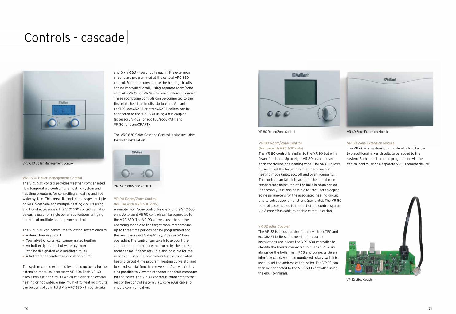
VRC 630 Boiler Management Control
The VRC 630 control provides weather-compensated
flow temperature control for a heating system and
has time programs for controlling a heating and hot
water system. This versatile control manages multiple
boilers in cascade and multiple heating circuits using
additional accessories. The VRC 630 control can also
be easily used for single boiler applications bringing
benefits of multiple heating zone control.
The VRC 630 can control the following system circuits:
A direct heating circuit
Two mixed circuits, e.g. compensated heating
An indirectly heated hot water cylinder
(can be designated as a heating circuit)
A hot water secondary re-circulation pump
The system can be extended by adding up to six further
extension modules (accessory VR 60). Each VR 60
allows two further circuits which can either be central
heating or hot water. A maximum of 15 heating circuits
can be controlled in total (1 x VRC 630 – three circuits
7170
Controls - cascade
VR 60 Zone Extension Module
The VR 60 is an extension module which will allow
two additional mixer circuits to be added to the
system. Both circuits can be programmed via the
central controller or a separate VR 90 remote device.
VR 32 eBus Coupler
The VR 32 is a bus coupler for use with ecoTEC and
ecoCRAFT boilers. It is needed for cascade
installations and allows the VRC 630 controller to
identify the boilers connected to it. The VR 32 sits
alongside the boiler main PCB and connects via an
interface cable. A simple numbered rotary switch is
used to set the address of the boiler. The VR 32 can
then be connected to the VRC 630 controller using
the eBus terminals.
VR 80 Room/Zone Control
(for use with VRC 630 only)
The VR 80 control is similar to the VR 90 but with
fewer functions. Up to eight VR 80s can be used,
each controlling one heating zone. The VR 80 allows
a user to set the target room temperature and
heating mode (auto, eco, off and over-ride/party).
The control can take into account the actual room
temperature measured by the built-in room sensor,
if necessary. It is also possible for the user to adjust
some parameters for the associated heating circuit
and to select special functions (party etc). The VR 80
control is connected to the rest of the control system
via 2-core eBus cable to enable communication.
VR 60 Zone Extension ModuleVR 80 Room/Zone Control
VR 32 eBus Coupler
VR 90 Room/Zone Control
VRC 630 Boiler Management Control
and 6 x VR 60 – two circuits each). The extension
circuits are programmed at the central VRC 630
control. For more convenience the heating circuits
can be controlled locally using separate room/zone
controls (VR 80 or VR 90) for each extension circuit.
These room/zone controls can be connected to the
first eight heating circuits. Up to eight Vaillant
ecoTEC, ecoCRAFT or atmoCRAFT boilers can be
connected to the VRC 630 using a bus coupler
(accessory VR 32 for ecoTEC/ecoCRAFT and
VR 30 for atmoCRAFT).
The VRS 620 Solar Cascade Control is also available
for solar installations.
VR 90 Room/Zone Control
(for use with VRC 630 only)
A remote room/zone control for use with the VRC 630
only. Up to eight VR 90 controls can be connected to
the VRC 630. The VR 90 allows a user to set the
operating mode and the target room temperature.
Up to three time periods can be programmed and
the user can select 5 day/2 day, 7 day or 24 hour
operation. The control can take into account the
actual room temperature measured by the built-in
room sensor, if necessary. It is also possible for the
user to adjust some parameters for the associated
heating circuit (time program, heating curve etc) and
to select special functions (over-ride/party etc). It is
also possible to view maintenance and fault messages
for the boiler. The VR 90 control is connected to the
rest of the control system via 2-core eBus cable to
enable communication.
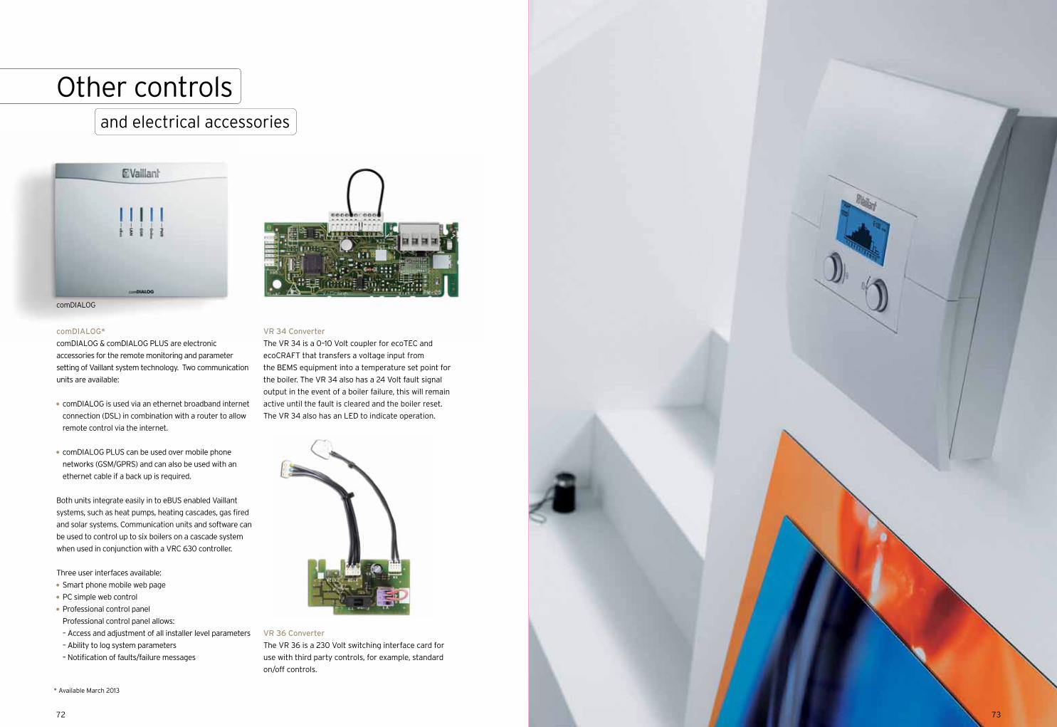
comDIALOG*
comDIALOG & comDIALOG PLUS are electronic
accessories for the remote monitoring and parameter
setting of Vaillant system technology. Two communication
units are available:
comDIALOG is used via an ethernet broadband internet
connection (DSL) in combination with a router to allow
remote control via the internet.
comDIALOG PLUS can be used over mobile phone
networks (GSM/GPRS) and can also be used with an
ethernet cable if a back up is required.
Both units integrate easily in to eBUS enabled Vaillant
systems, such as heat pumps, heating cascades, gas fired
and solar systems. Communication units and software can
be used to control up to six boilers on a cascade system
when used in conjunction with a VRC 630 controller.
Three user interfaces available:
Smart phone mobile web page
PC simple web control
Professional control panel
Professional control panel allows:
– Access and adjustment of all installer level parameters
– Ability to log system parameters
– Notification of faults/failure messages
VR 34 Converter
The VR 34 is a 0–10 Volt coupler for ecoTEC and
ecoCRAFT that transfers a voltage input from
the BEMS equipment into a temperature set point for
the boiler. The VR 34 also has a 24 Volt fault signal
output in the event of a boiler failure, this will remain
active until the fault is cleared and the boiler reset.
The VR 34 also has an LED to indicate operation.
VR 36 Converter
The VR 36 is a 230 Volt switching interface card for
use with third party controls, for example, standard
on/off controls.
comDIALOG
Other controlsand electrical accessories
* Available March 2013
7372

Low loss headers and low loss plate heat exchangers
System accessories
7574

7776
Boiler Low loss header
rt
ecoCRAFT 806 WH 95 20
ecoCRAFT 1206 WH 160 20
ecoCRAFT 1606 WH 160 20
ecoCRAFT 2006 WH 280 20
ecoCRAFT 2406 WH 280 20
ecoCRAFT 2806 WH 280 20
atmoCRAFT 654 WH 95 15
atmoCRAFT 754 WH 95 15
atmoCRAFT 854 WH 95 15
atmoCRAFT 1154 WH 95 15
atmoCRAFT 1304 WH 160 15
atmoCRAFT 1504 WH 160 15
atmoCRAFT 1654 WH 160 15
Boiler Low loss header
rt
ecoTEC 46 WH 40 20
ecoTEC 46 (X2/3) WH 95 20
ecoTEC 46 (X4) WH 160 20
ecoTEC 65 WH 95 20
ecoTEC 65 (X2) WH 95 20
ecoTEC 65 (X3) WH 160 20
ecoTEC 65 (X4) WH 280 20
ecoTEC 80 WH 95 20
ecoTEC 80 (X2/3) WH 160 20
ecoTEC 80 (X4) WH 280 20
ecoTEC 100 WH 95 20
ecoTEC 100 (X2) WH 160 20
ecoTEC 100 (X3) WH 280 20
ecoTEC 120 WH 95 20
ecoTEC 120 (X2) WH 160 20
ecoTEC 120 (X3) WH 280 20
Boiler Low loss header rt
ecoTEC 80 (X2) WH C 110 20
ecoTEC 80 (X3) WH C 160 20
ecoTEC 80 (X4) WH C 280 20
ecoTEC 80 (X5) WH C 280 20
ecoTEC 80 (X6) WH C 280 20
ecoTEC 100 (X2) WH C 110 20
ecoTEC 100 (X3) WH C 280 20
ecoTEC 100 (X4) WH C 280 20
ecoTEC 100 (X5) WH C 350 20
ecoTEC 100 (X6) WH C 350 20
ecoTEC 120 (X2) WH C 160 20
ecoTEC 120 (X3) WH C 280 20
ecoTEC 120 (X4) WH C 280 20
ecoTEC 120 (X5) WH C 350 20
ecoTEC 120 (X6) WH C 350 22
The main purpose of the low loss header is to maintain correct flow of water through the boiler and allow a
constant temperature supply of water to multiple heating circuits downstream of the low loss header connection.
These heating circuits may have different temperature and flow rate requirements (e.g. underfloor heating and
radiator circuits). Cooler return water from the heating circuits is mixed with water from the boiler in the low loss
header. An NTC (supplied) is used to monitor the temperature of water supplied by the boiler. It is recommended
that a suitable strainer is fitted in the return flow between the low loss header and the heating circuits as a
precaution to prevent system dirt from entering the boiler.
Low loss headers
Model Article number
Connection size
Header width
Header depth
Totalheight
Insulation dimensions
Distance between connections (boiler side)
Distance between connections (heating circuit side)
Height from floor
Maximum flow rate m3/hr
Flange type
WH 40 306720 1 1/4” BSP (f) 115 115 500 115/115 280 340 N/A 3.5 N/A
WH 95 306721 2” BSP (f) 155 155 750 155/155 470 540 N/A 8 N/A
WH 160 306726 DN65 120 120 1350 220/220 900 900 300 12 PN6
WH 280 306725 DN80 160 160 1390 260/260 930 930 300 21.5 PN6 All dimensions in mm
WH 95 WH 160 WH 280
System accessories
Model Article number
Connection size
Header width
Header depth
Totalheight
Insulation dimensions
Distance between connections (boiler side)
Distance between connections (heating circuit side)
Height from floor
Maximum flow rate m3/hr
Connection type
WH C 110 0020107874 DN 65 510 100 795 N/A 211 400 25 9.5 Flange PN6
WH C 160 0020107875 DN 65 510 120 795 N/A 211 400 25 12 Flange PN6
WH C 280 0020151859 DN 100 510 160 795 N/A 211 400 25 21 Flange PN6
WH C 350 0020107876 DN 100 510 200 795 N/A 211 400 25 29 Flange PN6
WH C 110 with insulation
WH C 280 with insulation
WH C 160 with insulation
WH C 350 with insulation
Low loss header in situ on boiler rig
Free standing and wall mounted low loss headers
Low loss headers suitable for use in pipework rigs
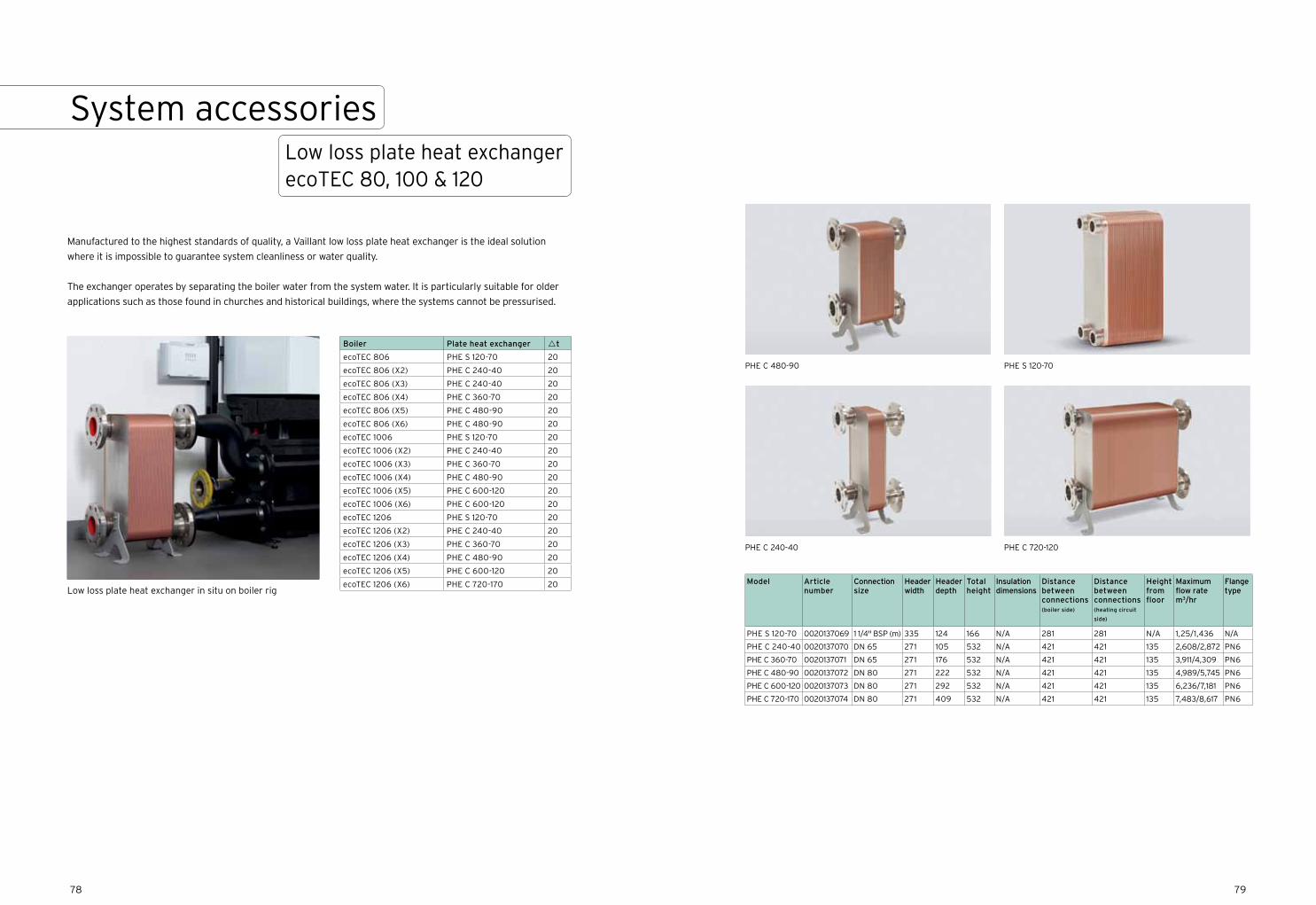
7978
Boiler Plate heat exchanger rt
ecoTEC 806 PHE S 120-70 20
ecoTEC 806 (X2) PHE C 240-40 20
ecoTEC 806 (X3) PHE C 240-40 20
ecoTEC 806 (X4) PHE C 360-70 20
ecoTEC 806 (X5) PHE C 480-90 20
ecoTEC 806 (X6) PHE C 480-90 20
ecoTEC 1006 PHE S 120-70 20
ecoTEC 1006 (X2) PHE C 240-40 20
ecoTEC 1006 (X3) PHE C 360-70 20
ecoTEC 1006 (X4) PHE C 480-90 20
ecoTEC 1006 (X5) PHE C 600-120 20
ecoTEC 1006 (X6) PHE C 600-120 20
ecoTEC 1206 PHE S 120-70 20
ecoTEC 1206 (X2) PHE C 240-40 20
ecoTEC 1206 (X3) PHE C 360-70 20
ecoTEC 1206 (X4) PHE C 480-90 20
ecoTEC 1206 (X5) PHE C 600-120 20
ecoTEC 1206 (X6) PHE C 720-170 20
Manufactured to the highest standards of quality, a Vaillant low loss plate heat exchanger is the ideal solution
where it is impossible to guarantee system cleanliness or water quality.
The exchanger operates by separating the boiler water from the system water. It is particularly suitable for older
applications such as those found in churches and historical buildings, where the systems cannot be pressurised.
Low loss plate heat exchanger in situ on boiler rig
Low loss plate heat exchanger ecoTEC 80, 100 & 120
System accessories
PHE C 480-90
PHE C 240-40
PHE S 120-70
PHE C 720-120
Model Article number
Connection size
Header width
Header depth
Totalheight
Insulation dimensions
Distance between connections (boiler side)
Distance between connections (heating circuit
side)
Height from floor
Maximum flow rate m3/hr
Flange type
PHE S 120-70 0020137069 1 1/4" BSP (m) 335 124 166 N/A 281 281 N/A 1,25/1,436 N/A
PHE C 240-40 0020137070 DN 65 271 105 532 N/A 421 421 135 2,608/2,872 PN6
PHE C 360-70 0020137071 DN 65 271 176 532 N/A 421 421 135 3,911/4,309 PN6
PHE C 480-90 0020137072 DN 80 271 222 532 N/A 421 421 135 4,989/5,745 PN6
PHE C 600-120 0020137073 DN 80 271 292 532 N/A 421 421 135 6,236/7,181 PN6
PHE C 720-170 0020137074 DN 80 271 409 532 N/A 421 421 135 7,483/8,617 PN6
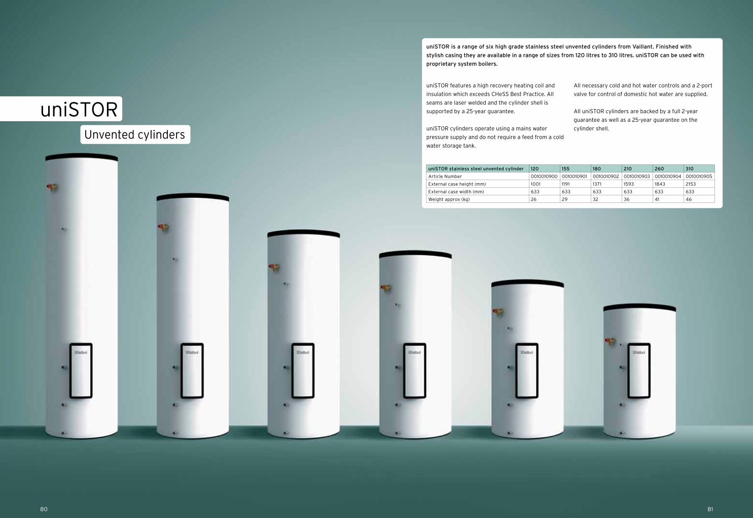
8180
Unvented cylinders
uniSTOR
uniSTOR features a high recovery heating coil and
insulation which exceeds CHeSS Best Practice. All
seams are laser welded and the cylinder shell is
supported by a 25-year guarantee.
uniSTOR cylinders operate using a mains water
pressure supply and do not require a feed from a cold
water storage tank.
All necessary cold and hot water controls and a 2-port
valve for control of domestic hot water are supplied.
All uniSTOR cylinders are backed by a full 2-year
guarantee as well as a 25-year guarantee on the
cylinder shell.
uniSTOR is a range of six high grade stainless steel unvented cylinders from Vaillant. Finished with
stylish casing they are available in a range of sizes from 120 litres to 310 litres. uniSTOR can be used with
proprietary system boilers.
uniSTOR stainless steel unvented cylinder 120 155 180 210 260 310
Article Number 0010010900 0010010901 0010010902 0010010903 0010010904 0010010905
External case height (mm) 1001 1191 1371 1593 1843 2153
External case width (mm) 633 633 633 633 633 633
Weight approx (kg) 26 29 32 36 41 46

8382
Customer service support
Installers
For installers wishing to purchase Vaillant products,
this is possible either over the counter or as a next day
service at most plumbing and heating merchants in
the UK.
To find contact details for your nearest Vaillant
sales representative call 0845 602 0262 or visit
www.vaillant.co.uk/commercial
For commercial service assistance call
0870 850 3072 or email [email protected]
For technical assistance call 0844 693 3133
or email [email protected]
To book or enquire about training courses and
centres in your area call 0845 601 8885
or email [email protected]
Specifiers
We can provide you with bespoke solutions to
accommodate a variety of different installations.
To discuss your requirements please contact us
using the details below.
To find contact details for your nearest Vaillant
sales representative call 0845 602 0262 or visit
www.vaillant.co.uk/commercial
To book or enquire about training courses
and centres in your area call 0845 601 8885
or email [email protected]
Reception
If you are unsure of who you need to speak to or
have a general enquiry, our friendly reception staff
will happily point you in the right direction.
Call reception on 0845 602 2922
Contact details

Notes Notes
8584
Vaillant Ltd.
Nottingham Road Belper Derbyshire DE56 1JT
Telephone 0845 602 2922 www.vaillant.co.uk [email protected]
100% of the inks used are vegetable oil based, 95% of press chemicals are recycled for further use and, on average 99% of any waste associated with this production will be recycled.
This brochure is printed on Core Silk, a paper containing 100% virgin fibre sourced from well managed, sustainable, FSC certified forests. The pulp used in this product is bleached using an elemental chlorine free (ECF) process.
The unavoidable carbon emissions generated during the manufacture and delivery of this brochure have been reduced to net zero through a verified carbon offsetting project.
01V
AC
OM
MB
RO
C
All information correct at time of print. Vaillant reserves the right to change content without notification. Image quality is subject to the printing process.
REG.NO. UK-000163