
COMMERCIAL & INDUSTRIAL WATER TREATMENT · - 1 - MAGNETIC FLUID CONDITIONING Active Scale Removal &...
22
- 1 - MAGNETIC FLUID CONDITIONING Active Scale Removal & Control COMMERCIAL & INDUSTRIAL WATER TREATMENT REDUCE COST OF OPERATING Boilers, Heat Exchangers, Condensers, Cooling Towers, Watermakers, Ice-makers etc. using Fresh Water, Sea Water, Hot Water or Steam. M.F.C.'s REDUCE Remove Old Scale 1. Chemical Costs Prevent New Scale Formation 2. Fuel Consumption Extend Equipment Life 3. Repair Expense Restore System Flow Rates 4. Cleaning Time Keep Equipment Clean 5. Electrical Use
-
Upload
duonghuong -
Category
Documents
-
view
214 -
download
0
Transcript of COMMERCIAL & INDUSTRIAL WATER TREATMENT · - 1 - MAGNETIC FLUID CONDITIONING Active Scale Removal &...

- 1 -
MAGNETIC FLUID CONDITIONING
Active Scale Removal & Control
COMMERCIAL & INDUSTRIAL WATER TREATMENT
REDUCE COST OF OPERATING Boilers, Heat Exchangers, Condensers, Cooling Towers, Watermakers, Ice-makers etc. using Fresh Water, Sea Water, Hot Water or Steam.
M.F.C.'s REDUCE Remove Old Scale 1. Chemical Costs Prevent New Scale Formation 2. Fuel Consumption Extend Equipment Life 3. Repair Expense Restore System Flow Rates 4. Cleaning Time Keep Equipment Clean 5. Electrical Use

- 2 -

- 3 -

Magnetic Fluid ConditionerFC Series
MFC Technology presents cost effective, non-chemical treatment for industrial and commercial Fuel, Oil & Water Systems. A variety of fluid instability factors cause the formation of insipient solids, sediments, and deposits that impact equipment performance and reliability in numerous applications. The FC Series of fluid conditioners reverses these processes, reducing maintenance and downtime, to increase productivity and reduce overall operating costs.
APPLICATIONS
- 4 -
In Diesel Fuel Systems, less than optimal fuel quality leads to poor filterability and incomplete combustion causing excessive exhaust and particulate emissions. Symptoms of poor fuel quality are clogged filters, tank sludge, premature injector and injection pump failure, insufficient RPM and engine output. Injector and pump damage is mostly due to the build up of asphaltene and other organic fuel component deposits of 5 micron and smaller. Algae-X Fuel Conditioning and Fuel Management Systems keep fuel clean and reduce the particle size of these organic compounds improving filtration, combustion and fuel stability.
In Crude Oil production, transportation and storage systems MFC (Magnetic Fuel Conditioning) technology is implemented to reduce, prevent and eliminate deposits of paraffin, asphaltene, scale, B S & W and tank high bottoms. MFC installations increase production flow, reduce downtime, extend maintenance intervals and in some instances prevent the necessity of mechanical or chemical treatment, the manual de-scaling of pumps and related equipment. In Storage Tanks & Pipelines the application of MFC technology enhances oil water separation, eliminates the need for costly toxic biocides and reduces drag in pipe lines. MFC systems significantly reduce corrosion & pitting, prevent and eliminate the formation of sludge & tank high bottoms and extend tank-cleaning intervals.
In Lube Oil & Hydraulic Fluid filtration and treatment equipment, MFC based recirculating systems (like FPS or STS) are implemented to improve the filterability, stability and service life of the oil. These systems significantly reduce maintenance & downtime, improving system reliability, extending replacement intervals of coalescer & filter elements.
In Water systems such as cooling towers, boilers and heat exchangers calcium carbonate and other dissolved salts form scale deposits. The traditional approach to de-scaling and scale prevention has been the continuous use of costly chemicals, or acid treatment and the manual removal of scale deposits. In-line installations of MFC systems offer a cost effective, safe and environmentally sound alternative. Non-chemical MFC water treatment and de-scaling systems change and inhibit the formation of calcite, promoting the formation of another forma of calcium carbonate crystals (aragonite). This material is not sticky, much smaller and easily removed during blow down.

Magnetic Fluid ConditionerFC Series
SPECIFICATIONS The FC Series of high capacity, high-pressure fluid conditioners are designed and built to customer specifications. FC equipment ranges in size from 1/2” female or male thread connectors up to large diameter flanged spool pieces for pipelines and tank farms. Standard pressure ratings range from 150 PSI up to 3000 PSI.
The housing and inside flow channels of all standard FC units are made of 304 or 316 stainless steel. Larger MFC’s for pipelines, tank farms and cooling towers can be built with a stainless steel interior and a steel housing. Standard magnetic circuitry is constructed with high-powered neodymium. FC Series is shock and vibration proof.
Data and specifications on pipe sizes and diameter, flow rates and operating pressures in the system are necessary information to determine the model, type and configuration of FC equipment for a particular application. For water and crude oil applications, we require information on the make up of the fluid, preferably in the form of a fluid analysis lab report.
INFORMATION TO DETERMINE FC SERIES DESIGN CRITERIA AND DIMENSIONS
Fuel, Oil, Crude Oil Data Requirements
Application Engine, generator, fuel forwarding pump, storage tank, pipeline, oil well, hydraulic system
- 5 -
Engine / Generator Make, Model, hp or kW
Line Size Fuel line size and thread (NPT, BSP) or flange
Flow Rate / Pressure Flow rate in GPM, GPH, l/min, tons/h / pressure in the system Tank Size Number, capacity & dimensions of tanks Pressure Drop Max. allowable pressure drop at MFC installation point Layout Flow schematic or drawing, piping, tank diagram Lifetime Warranty and Performance Guaranty Made in the U.S.A.
The ALGAE-X® manual “Commercial and Industrial Fluid Treatment” provides further information, standard questionnaires and examples of principle system schematics. For system design and additional information please contact us directly.
Water Data Requirements Boiler, heat exchanger, cooling tower, water supply, AC Application
Line Size Line diameter and thread (NPT, BSP) or flange Flow Rate / Pressure Flow rate in GPM, GPH, l/min, tons/h / pressure in the system Pressure Drop Max. allowable pressure drop at MFC installation point Layout Flow schematic or drawing, piping diagram Lifetime Warranty and Performance Guaranty Made in the U.S.A.
FC Systems can be purchased or leased.
ALGAE-X® Total Fuel Management Systems
© Copyright 2005, ALGAE-X® International www.algae-x.net • 877-425-4239 • [email protected]

Heat transfer efficiency curve (Donohue and Sarno) Lines A, B, C, D and E represent the common elements found in an average scale deposit. The composition of your deposit will determine the final efficiency loss. It has been our experience that the average scale deposits of .025 (calling card thickness) can cause as much as a 28% - 30% loss in heat transfer in a boiler. In a 100 Hp boiler operating 24 hours with a load cycle average of 10 hours per day operating 240 days per year, a 15% efficiency gain could amount to 36 days worth of fuel cost. In an air-conditioning system two areas are important: The chilled water cooler and the condenser. In the condenser a .025 deposit could amount to as much or more than 30% of the heat transfer efficiency. In the chiller this .025 deposit would be an additional loss in excess of 50%.
- 6 -
- 7 -
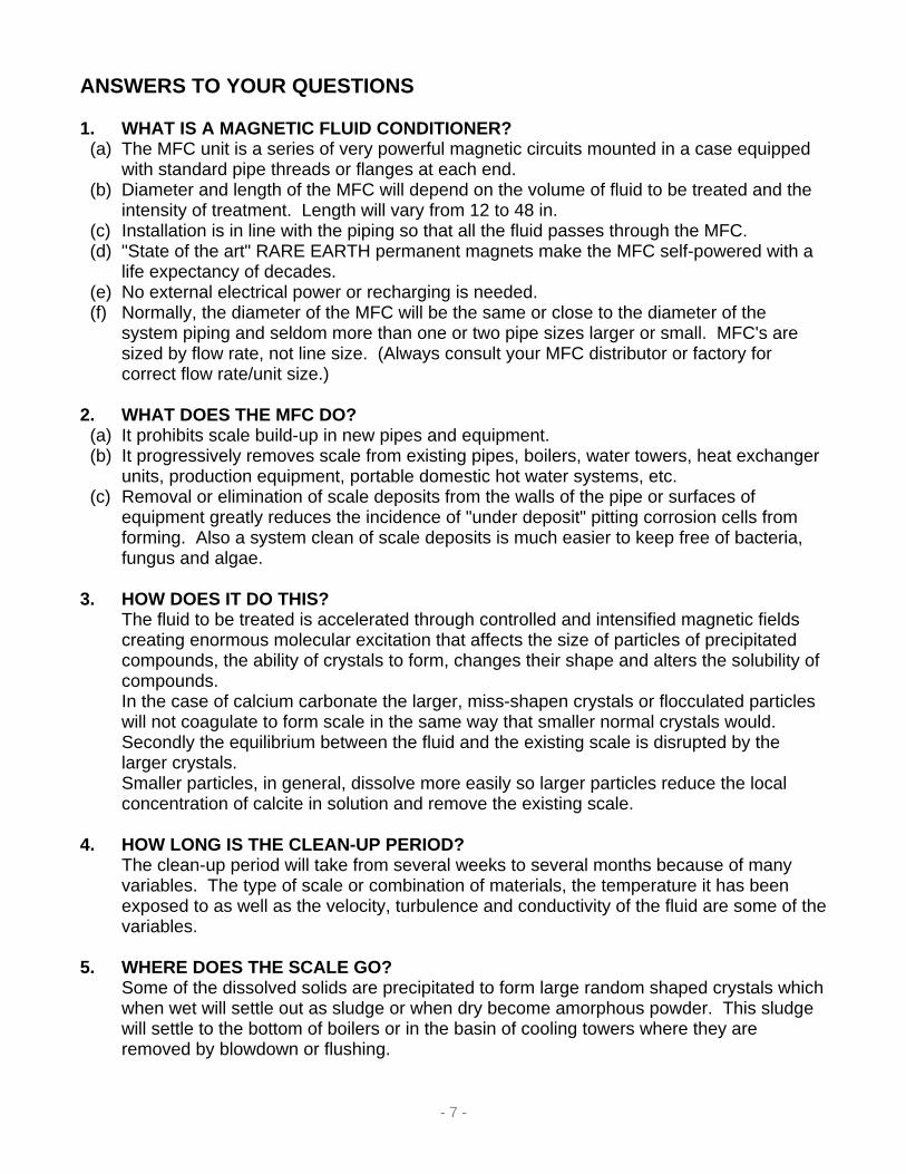
ANSWERS TO YOUR QUESTIONS 1. WHAT IS A MAGNETIC FLUID CONDITIONER? (a) The MFC unit is a series of very powerful magnetic circuits mounted in a case equipped
with standard pipe threads or flanges at each end. (b) Diameter and length of the MFC will depend on the volume of fluid to be treated and the
intensity of treatment. Length will vary from 12 to 48 in. (c) Installation is in line with the piping so that all the fluid passes through the MFC. (d) "State of the art" RARE EARTH permanent magnets make the MFC self-powered with a
life expectancy of decades. (e) No external electrical power or recharging is needed. (f) Normally, the diameter of the MFC will be the same or close to the diameter of the
system piping and seldom more than one or two pipe sizes larger or small. MFC's are sized by flow rate, not line size. (Always consult your MFC distributor or factory for correct flow rate/unit size.)
2. WHAT DOES THE MFC DO? (a) It prohibits scale build-up in new pipes and equipment. (b) It progressively removes scale from existing pipes, boilers, water towers, heat exchanger
units, production equipment, portable domestic hot water systems, etc. (c) Removal or elimination of scale deposits from the walls of the pipe or surfaces of
equipment greatly reduces the incidence of "under deposit" pitting corrosion cells from forming. Also a system clean of scale deposits is much easier to keep free of bacteria, fungus and algae.
3. HOW DOES IT DO THIS? The fluid to be treated is accelerated through controlled and intensified magnetic fields
creating enormous molecular excitation that affects the size of particles of precipitated compounds, the ability of crystals to form, changes their shape and alters the solubility of compounds.
In the case of calcium carbonate the larger, miss-shapen crystals or flocculated particles will not coagulate to form scale in the same way that smaller normal crystals would.
Secondly the equilibrium between the fluid and the existing scale is disrupted by the larger crystals.
Smaller particles, in general, dissolve more easily so larger particles reduce the local concentration of calcite in solution and remove the existing scale.
4. HOW LONG IS THE CLEAN-UP PERIOD? The clean-up period will take from several weeks to several months because of many
variables. The type of scale or combination of materials, the temperature it has been exposed to as well as the velocity, turbulence and conductivity of the fluid are some of the variables.
5. WHERE DOES THE SCALE GO? Some of the dissolved solids are precipitated to form large random shaped crystals which
when wet will settle out as sludge or when dry become amorphous powder. This sludge will settle to the bottom of boilers or in the basin of cooling towers where they are removed by blowdown or flushing.
- 8 -
Side stream solids separation equipment can be effective in removing these solids from
some systems. A portion of the existing scale will return to solution and be carried away in the bleed off. The rest of the scale may fall off in softened pieces and have to be physically removed from the system several times during the clean-up period. It is a slow but safe way to remove scale.
6. WILL IT WORK ON ALL TYPES OF WATER? The MFC is most effective in hard water, salt water and soft treated water. It also works very well combined with chemical treatment so changing from chemical to
magnetic treatment is easy. The combination of both chemical and magnetic treatment makes the clean up faster.
The reaction in highly conductive sea-water and oil field production water is more pronounced. Scale problems in oil well pumps have been eliminated with MFC's where the total dissolved solids have been over 200,00 PPM and the hardness more than 20,000 PPM.
7. WILL IT TREAT LARGE SYSTEMS? There is no limit to the size that MFC's can be built. They can be manifolded and only the
required number of units used to meet the flow rate. One large unit can treat the discharge of many pumps. Smaller units on the discharge of
each pump may be required if the pumps cycle on/off. Units have been installed on recirculating systems in excess of 30,000 feet in length. 8. IS THE MFC A WATER SOFTENER? No. The MFC is not a water softener, it does change the state of the solids in the water
and reduce surface tension. In most cases the use of a water softener can be discontinued. An exception may be a
boiler under heavy load with no condensate return and a very hard raw water supply. If scale control has not been achieved with a water softener and chemicals, then leave the existing treatment in place until control is achieved with the magnetic unit. Scale control can then be cut back or eliminated. Just getting the scaling problems under control will make the MFC cost effective in severe cases as the above described boiler.
9. DO I STILL NEED CHEMICALS? The MFC unit can eliminate the use of chemicals in some cases, but more likely it will
greatly “reduce” the amount of chemistry and frequency it needs to be applied. Reduction of chemical additives for control of microbes is another benefit of installing an MFC in your system.
10. WHAT IS THE DEFINITION OF “NEGLECTED”? If the magnetic units are installed and then the system neglected it will start to clean, then
scale up again. The magnetic system is much easier to maintain than a chemical only system. However,
during the clean-up period solids must be flushed from the system and correct bleed-off or blowdown procedures followed. After the initial clean-up period, the system will be very easy to maintain.

- 9 -
11. HOW DO I KNOW IT'S WORKING? (a) BOILER? Visual inspection before and 30 to 60 days after the MFC installation will demonstrate the
clean-up. Although a TDS continuity test will indicate its reaction--the operator or plant supervisor has schedules set up for blowdown according to PPM concentration in boiler water. Our unit will increase the reading, showing the scale coming into suspension and requiring more frequent blowdowns initially. As the scale is removed, the TDS - PPM will again recede and blowdown exchange will be better and fuel consumption will go down.
(b) AIR CONDITIONING EQUIPMENT? Monitor the temperature spread across the condenser and watch it return to the original
specs. Since the condenser increases in efficiency, the load can be reduced. Record this change to calculate savings. Head temperature and oil temperature both will decrease. This load change has two primary benefits, (a) dollars saved in energy consumed, and (b) increases life of equipment.
(c) INDUSTRIAL HEAT EXCHANGERS? Monitor in/out temperatures and pressures on both sides of the heat exchanges as it
returns to the original specifications. (d) DOMESTIC HOT WATER SYSTEMS? Potable water can be safely treated with magnetics. MFC's do not introduce any foreign
contaminates which would alter the purity. Normal blowdown of the storage tank will reveal a residue of crystal deposits being discharged from the bottom drain. Scheduled blowdown of the hot water storage tank should not be neglected. By monitoring, you will note an increase in temperature of the return hot water line. You will also note a shorter recovery time. This indicates a more efficient heat exchanger. Sectioning a piece of the water line at a remote location will provide a method to visibly inspect the removal rate. Water flow rates will increase at all points in the system.
12. WHAT ABOUT PRESSURE DROP? As the fluid to be treated is accelerated through the magnetic fields a pressure drop
occurs across the MFC. This pressure drop can be as little as one PSI or as much as 10 PSI depending on the system. As a general rule 2-6 PSI is normal.
The feet of head, pump specs., type of system, flow rates required, etc., are all taken into consideration in selecting the right size and model MFC For your system.
The pressure drop and more are gained back when the frictional losses due to scale are eliminated from the system.
13. HOW ARE MFC's INSTALLED? Any person with a basic understanding of elementary pipe fitting can install the magnetic
units in the pipe. At your request Algae-X International will provide you with a detailed instruction manual or insure that one of our Representatives are present for the installation.
Our sales reps will be pleased to inspect your system and gather information to properly size your MFC's.

- 10 -
New Scientist 18 February 1988
Lifting the Scales From Our Pipes
Magnetic fields change the way crystals form in fluids. This could prevent the formation of scale in pipes and boilers.
John Donaldson and Sue Grimes
INDUSTRIALIST don't usually call in scientists to convince their customers that a process
works but HDL Fluid Dynamics, based in Amsterdam, was in great difficulty. Engineers would not believe that scale deposited in pipes by hard water would disappear or reduce if the water flowed through a magnetic field. The company asked us to investigate that fundamental process of what was described as magnetic descaling. At this state, we said -We don't believe you either'. But then we visited industrial sites where HDL had installed magnetic units and found that they did indeed remove scale from pipes at the time; we could not explain why the magnetic treatment worked.
Scale is one of the banes of industry .It narrows pipes, blocks jets and is expensive to cleanup. Mineral compounds in the water, such as calcium or magnesium carbonate, sulfate or chloride form these deposits when they precipitate out of the water lining pipes with the furry deposits you can see in any kettle.
Researchers first discovered in the 19305 that magnetic treatment could remove scale from pipes, but no one could explain why or how this happened. The charlatans began selling toy magnets as a quick cure for blocked pipes and furred kettles. These weak magnets did not work, and the technique fen into disrepute. Now Britain spends around 600 million each year to clean or to repair pipes and boilers damaged by scale, so it is worth following up any technique that could alleviate the problem.
Calcite is one of the main culprits of scale. It is the comments form of calcium carbonate, occurring naturally as an essential ingredient of limestone, marble and chalk. Water passing over such rocks dissolves calcite, which may then form a stony scale inside pipes and tanks Rock-like deposits appear on boiler walls and tubes when water heats up or evaporates. The problem increases, as water gets hotter. Water with 145 parts per million of calcite, flowing at 5.000 liters a day, can produce 4.8 kilograms of scale each year at 60oC. At 80oC, it produces 29.9 kilograms. In a hot-water tank at McMullen’s, the brewers, so much calcite scale built up on the 69.000-litre vessel that is needed a regular shutdown for descaling. The firm had to build scaffolding inside the tank to support people while they chipped away the scale, which was about 2 centimeters thick This took around ten days -and a large amount of descaling chemical. After installing a magnetic unit, the scale at the next shutdown was soft and thin. The cleaners could brush it off in only two to three days. They needed far less descaling fluid.
HDL's magnetic units contain four bar magnets mounted inside a stainless steel tube with flanges to attach it to other pipes. They can fit in a system vertically or horizontally and, as the magnets are permanent, they do not need power connections. Magnets in the unit consist of 24 percent cobalt, 14 percent nickel, 8 percent aluminum and 3 percent copper. The balance is iron. The manufacturer of the magnets, Magnetic Developments, melts the raw materials in a high frequency furnace at 1,100oC, and then casts them in sand. It "fast cools" the bars to prevent polymorphic iron forming. The irregular crystals of this kind of iron lower the performance of magnets. Heating the rough castings to 930oC cleans and tempers them. Cooling them at a controlled rate in a magnetic field produces permanent magnets. The manufacturer coats the magnets with polytetrat1uoroethylene, which is highly resistant to oxidation and the action of chemicals. It also strengthens the magnets. A coating of PTFE prevents corrosion in abrasive phosphate, for example, systems in the pre-treatment of steel.

- 11 -
Magnetic units can be from 2 centimeters to 35 centimeters in diameter and from 2 centimeters to 45 centimeters long. They can cope with flow rates of up to 9.000 liters per minute. Fluids pass the horizontal poles of the magnets and constrictions in the tubes - venturis - vary the rate at which fluids flow through the units, varying the strength of the magnets in a unit affects the size of particles precipitating out of a fluid. Increasing the strength of a fie1d through which water containing dissolved calcium carbonate flows, for example, produces larger crystals. But, there appears to be a limit to this effect. A typical unit has a field strength of between 25 gauss to 2,500 gauss, depending on its function .Increasing a field to 25.000 gauss did not increase the size of particles by a factor often.
Over the past three and a half years, we have investigated the effect of magnetic fields on fluids at City University and have monitored industrial trials. We can now show that the influence of magnetic fields on precipitation extends beyond simple descaling - - it can prevent scale from forming. We examined its action on other fluids, not just water, and found beneficial effects in metal pretreatment (see box).
How to increase efficiency in steel pre-treatment If you don't protect it, steel win form oxides on its surface. For cars and vans this quickly
leads to corrosion. Car manufacturers treat steel by adding a layer to which paint will adhere to protect it.
To "pre-treated" steel, you bath it in solutions of zinc, manganese, iron or chromium phosphates that are on the edge of super-saturation. After spraying and dipping the metal, a thin layer of phosphate coats the surface of the steel. A sludge also forms as a result of chemical action between the pre-treatment solution and the steel. As it dries, this sludge can convert into phosphate scale.
Scale blocks jets and pipes, forming layers on the surfaces of heat exchangers and tanks. A final rinse of the treated steel with hard water can also deposit scale on its surface when the calcite in the water precipitates out as calcium phosphate or mixtures of calcium carbonate and calcium prostate. Bedford had this problem at its steel pre-treatment plant for van bodies at Luton. Usually, scales of phosphates rather than hard-water scale are the main problem.
We monitored the results of installing a magnetic unit in the Bedford plant in the pipes that carried water for rising. The manufacturer washed the steel with water after dipping it in a bath of alkali. After the unit arrived, the calcium phosphate scale on the walls of the dip tank and on the housing walls of the tank disappeared. Originally the scale had been 6 to 8 millimeters thick in a tank with a capacity of 1.63 cubic meters. Bedford saved an estimated $22,000 a year on cleaning its tanks with acid after installing a magnetic unit.
We also monitored the effects of magnetic units in spray systems that used zinc phosphate. We found that less sludge formed and that consumption of pre-treatment fluid was cut. This suggests that more zinc phosphate remained in solution and less converted to unwanted sludge. Brush Switchgear, for example, reduced its use of phosphate by 20 percent. They also found that spray jets did not get blocked quite as quickly. At the Servis Group, the benefits of installing a magnetic unit included a reduction of 80 percent in blocked jets. In addition, Servis also improved its heating efficiency because they now only a slight amount of scale built-up on the heating coils. It had less sludge to get rid of. The firm also saved 30 man/hours a week on cleaning jets and pipes and 40 to 50 man/hours every six weeks on a cleanup of the whole plant. When the factory had to closed, the downtime was cut by a day.
Another case study of a wash system for a phosphating process for steel treatment confirmed these findings. In this plant, scale from hard water blocked up jets every few weeks. After putting a magnetic unit the water pipe, the plant did not close to clean the jets for more than a year.

- 12 -
We monitored industrial studies on the magnetic treatment of fluids to prevent scale from forming in systems ranging from plate heat exchangers to the humidifier in a chicken hatchery. In all cases, the magnetic field lessened the build-up of scale significantly. We collected data on energy savings as well as on the removal of scale by measuring, for example, pumping energies and the increase in efficiency in heat transfer.
At a GKN plant, photographic monitoring of a cooling system showed that a magnetic unit was removing existing calcite scale, and that further hard scale was not forming. Another study involved fitting a magnetic unit to a hard-water supply feeding the boilers of humidifiers at a computer center. Although the typical life of a boiler unit in the untreated system was 1,000 to 1,500 hours, five of these boilers supplied with water passed through a magnetic unit, still functioning after and average of 2,400 hours.
Similar results came from tests at the Sovereign Hatchery, Suffolk. Hard-water blocked spray jets every 21 days in the humidifier system and caused a gradual buildup of calcite on the walls of the chicken hatchery where it had splashed. Within three weeks of the installation of a magnetic unit, the problems with blocked jets stopped. HDL continued treatment. It found that scale on the hatchery walls decreased, making them easier to keep clean.
In our preliminary laboratory studies we found that over a period we could remove scale from a pipe lined with calcite deposits if we ran along it hard-water that had passed through a magnetic field. We concentrated on how the deposits form, rather than on how they disso1ve, by investigating the process of precipitation that leads to scale. We carried out experiments in duplicate with magnetic and dummy units of the same geometry to eliminate changes unrelated to magnetic fields. We pumped the fluid from a reservoir through a unit into a test zone where precipitates were formed. Collecting samples from this zone, we analyzed the precipitates with a variety of techniques, including analysis of the size of particles, electron or optical microscopy, X-ray diffraction and chemical analysis.
Our results showed that the magnetic field affected precipitation. It could change the size of panicles of precipitated compounds, the ability of crystals to form, their shape and alter the solubility of compounds. In the case of calcium Carbonate, we can show that particles precipitated from hard water increase in size when the water passes through a magnetic field.
An increase in the size of particles can have two beneficial effects. First, the larger crystals will not coagulate to form a scale in the same way that smaller crystals would. This is the purpose of the magnetic units. Secondly, the presence of the larger crystals disrupts the equilibrium between the fluid and any existing scale. Smaller particles, in general, dissolve more easily so larger panicles will reduce the local concentration of calcite in so1ution - and remove the existing scale.
Expanding The Crystal World
Electron micrographs of calcium carbonate scale produced by evaporation show that
crystal size increases when the fluid is treated magnetically. Associated with these differences in size are changes in the crystallinity - or the ability of precipitates to form crystals - that you can observe after magnetic treatment. The magnetic field affects the growing crystals. Under an electron or optical microscope, you can see, for example, that in a solution of calcium sulfate dehydrate large single crystals form in the absence of a magnetic field. Within a magnetic field, smaller groups of crystals precipitate.
Studying the solubility of calcium phosphate, we found that magnetic fields alter the solubility or levels of super-saturation of solutions used in the phosphating industry. We found that comparing the results of using dummy or real magnetic units, more calcium phosphate stays in solution in magnetically treated fluids.

- 13 -
On a crystal, the external faces are the slowest to grow as the crystal deve1ops. Adding chemicals to a saturated solution can change the growth on one set of crystal planes relative to other planes, altering the shape of the crystals. There is considerab1e evidence that applying a magnetic field to growing crystals also changes the relative rate of growth of their external faces. These changes in crystallinity and in crystal structure must arise because of interaction between the field and the nucleating and growing crystals.
Evidence from the precipitation of calcium carbonate and zinc phosphate suggests that, under certain conditions, you can alter the chemical phase of these precipitates if you treat the fluids containing them with magnets. This could result only from changes in the equilibrium between the fluid and the precipitate altering the relative stabilities of two phases with closely matching lattice energies. When we evaporated hard-water, for example, we found that before treatment the precipitate of calcium carbonate contained calcite and aragonite - in a ratio of about 4.1. After treatment, the ratio of these phases was about 1:4. Electron micrographs and X-ray diffraction patterns show these changes clearly.
There are three possible explanations of why the magnetic devices prevent scale from forming and encourage scale to dissolve. First, turbulence. In a system where a fluid passes through a slit in a pipe of a larger diameter, turbulence occurs. There is no doubt that the flow of liquid through the magnetic units is very turbulent; the geometry of the unit narrows the pipe. However, we found no evidence that you could produce the same effects on crystal growth, precipitation and solubility with non-magnetic dummy units of the same geometry as the real units. Turbulence helps to prevent small imperfectly formed crystallites from aggregating to form scale and the descaling process, but these effects are essentially secondary to the effects of a magnetic field on a fluid.
The second explanation could be the Lorentz effect. The combined effects of an applied magnetic field, a charged species, the induced magnetic field on the charged species and rate of flow of the fluid could together produce energy that, by normal collision processes between molecules could act downstream in the system, removing or preventing scale. The amount of energy produced in this process, in typical scale-forming systems, is likely to be small. Although it may contribute to the overall process, it seems unlikely that it explains the observed phenomena fully. The energy available to single ions from this process might perhaps alter the way in which these ions interact with the growing crystals in the fluid. This energy might be important in modifying the way in which crystals form around a nucleus.
Changes in Nuclei
The third explanation covers everything we have seen so far - the magnetic field is
modifying crystal nuclei. The nuclei on which the crystals start growing, and the growing crystallites, are very small and will have charged surfaces. As they pass through the magnetic field, these charged particles encounter considerable forces as the magnetic field interacts with them. This distinguishes fluids treated magnetically from untreated fluids. The magnetic field acts at the surface, this alters the growth of the crystals in general and on specific planes. Such a modification of the way nuclei form around which crystals and they way in which crystals grow explains everything we have seen. The size of the crystal will change as the pattern of growth in the field alters. The ability to form crystals alters as the relative rate of growth of specific planes of the crystals responds to the magnetic field. This also changes the crystal's shape. As the relative energies available to the growing crystals vary with and without a magnetic field, so will the crystal phase. In turn, as crystals grow differently, their solubility or levels of super-saturation in fluids alters. This explains why scale starts to dissolve; the equilibrium between the fluid and the precipitate changes because crystals are growing in a different way. The rate at which crystals form changes as well.

- 14 -
At the interface between solids and fluids, diffusion layers arise between the solution and the faces of the growing crystal. The growing faces each carry a distinctive charge. How the magnetic fluid affects the surface of the crystal and the diffusion layer is critical. These phenomena govern the effect that the field will have on crystal growth. In a simple precipitating solution, the field will affect the charged surface of the growth nuclei. The anions and cations. It is in the region where the fluid meets the solid that we must look for explanations of the effects of magnets on fluids. Currently we are investigating ways in which a magnetic field can alter crystal nucleation and how the field affects the transport of ions through the barrier layer towards the charged surface of growing crystals. We now believe that the main effect of the field is its interaction with crystallization nuclei. This opens up the removal and prevention of scale to a wide range of studies. Magnetic effects on fluids could affect processes throughout the chemical industry from hydrometallurgy to filtration.
A magnetic field will interact with any substance that carries a charge, however small, in any fluid. This has led us to new areas of research. Some have produced interesting results, leading to commercial exploitation. We found, for example, that magnetic treatment of cement and ceramic slurries can improve their strength. The oil industry now funds research to reduce scale in North Sea rigs. Pumping solvents into the bedrock forces up oil but scale from dissolved bedrock can damage pipes and pumps. Reducing or eliminating scale would save the oil industry a barrel of money.
Professor John Dona1dson and Dr. Sue Grimes research the effects of magnetic fields on fluids in the
Chemistry Department of City University of London.

SCHEMATIC DIAGRAM OF TYPICAL STEAM BOILER SYSTEM
BOILER TYPES
Boilers generally come in two types : The FIRETUBE Boiler is so named because the FIRE or hot gases pass THROUGH the boiler tubes. The boiler water surrounds the outside of the boiler tube. Approximately 80% of the boilers in use are FIRETUBE Boilers. In a FIRETUBE Boiler, the FIRE is in the TUBE. The WATERTUBE Boiler is so named because the water passes trough the tubes and the fire surrounds the tubes. It is easily recognized since the boiler is rectangular in shape. These boilers are usually large, 1000HP and up. In a WATERTUBE Boiler, the WATER is in the tube. Each type of boiler has various advantages and disadvantages which deal with initial cost, ease of installation, type of steam application.
- 15 -
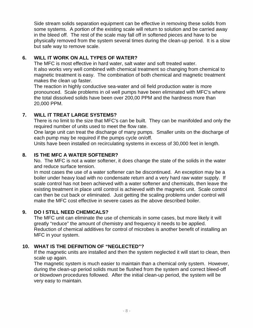
MFC INSTALLATION – BOILER APPLICATION
Sodium Sulfite is used to remove free dissolved oxygen to prevent pitting corrosion.
- 16 -

- 17 -

MFC INSTALLATION – COOLING TOWER APPLICATION
The MFC units are equipped with a conductivity meter connected to the test port for an automatic blow down after reaching a certain amount of TDS in the water.
- 18 -

INFORMATION SHEET FOR COOLING TOWERS, OPEN CONDENSER’S etc.
Co. Name: ___________________________ Attn.: ___________________________ Address: ___________________________ ___________________________ Phone: ___________________________
( A ) Air Conditioning ( B ) Refrigeration ( C ) Ice Maker ( D ) Heat Transfer ( E ) Other Tonnage of air cond, refrig, or ice: ______________________
Number of Units: ______________________
Heat Exchanges Or Condensers Are:
Shell & Tube Plate
Open Condenser Open Pipe Heat Exch. Please give a description of system and history of treatment. ____________________________________________________________________________________________________________________________________________________________________________________________________________________
SYSTEM TYPE
PIPE SIZE PRESSURE TEMPERATURE
1. ________ _________ _____________ 2. ________ _________ _____________ 3. ________ _________ _____________ 4. ________ _________ _____________
Make up water per day _________________________________ Flow Rate when making up _____________________________
DATA FROM LOCATIONS 1,2,3 & 4 OF ABOVE SKETCH
PUMPS
Number of pumps _____________________ Use back of info. Sheet for additional pumps. Manufacturer __________________ Model __________________ Horsepower __________________ R.P.M. __________________
Size Suction __________________ Size Discharge __________________ Pressure at Discharge __________________ Plate Data G.P.M. __________________ Plate Data ft. Head __________________
PUMP No. 1
ATTACHMENTS
Scale Sample Water Sample Scale or Water Analysis Drawings or Prints of System
Pump Mfg. Data/pump curves etc. Chemical treatment reports
- 19 -

FLUID TREATMENT Data Requirements
WATER INFORMATION – Water analysis data ( please attach report if available and describe by color and smell and any health related problems.)
Hardness ____________________ Remarks ________________________________ Iron _________________________________________________________ Manganese ____________________________________________________ Ph ___________________________________________________________ TSS __________________________________________________________ Temperature ___________________________________________________ INSTALLATION DATA: Provide Pipe Size ______ Pipe Type/Material ______ Diameter________ Gal/Minute ________ ( Please add diagram of installation )
Please detail Equipment, Maintenance Procedure, Cost and Labor ______________________________________________________________________________ ______________________________________________________________________________ ______________________________________________________________________________ NAME ______________________ TITLE __________________________
COMPANY NAME ________________________________________________ ADDRESS ______________________________________________________
CITY ___________________ STATE ____________ ZIP _____________ PHONE ________________________ FAX ___________________________
- 20 -

INFORMATION SHEET FOR BOILERS
- 21 -
Co. Name:_________________ Attn.:_____________________
Address:__________________ Fire Tube Water Tube _________________________ Steam Hot Water Heating _________________________ Condensate Return Yes Domestic Hot Water Phone:___________________ Condensate Return No
BOILER FEED PUMP Please give a description of the boiler’s and system and what
they are used for _______________________________________________ _______________________________________________ _______________________________________________ _______________________________________________
RATING
BOILER TYPE
Type: _____________ Manufacturer: _____________ Model:_____________
Plate Data G.P.M:_____________ Plate Data Ft. Head:_____________
Size Suction: _____________ Size Discharge: _____________
Horsepower: _____________ R.P.M.: _____________
____________________________________________________________________________________________________________________________
Lbs. Of Steam Per Hour ________________________ Horsepower ________________________
Other Rating ________________________ Required make up ea. Boiler G.P.M.________________________
Operating Pressure ________________________ Percent of Condensate Returned ________________________
ATTACHMENTS ADDITIONAL INFORMATION
Make up Water Line Size ________________________ Pipe Size & Sch. Of Pipe ________________________ Pipe size at Discharge of Feed Pump ________________________ Frequency of Boiler Blow Cleaned ________________________ Is it Cleaned by Mechanical/Acid ________________________ What is Condition prior to Cleaning ________________________
For domestic Hot Water give return _________________________ Line/s size and recirculating pump/s G.P.M. _________________________ Max. Make up for Domestic Hot Water G.P.M. _________________________
Raw Water Analysis
Boiler Water Conditions Scale Analysis
Drawings or Prints Pump Mfg. Info. Feed Pumps
Past Cleaning Records Inspection Reports
Chemical Treatment Records
Co. Name: _______________ Attn: _______________
Address: _______________ ________________________ ________________________
Phone: _______________
INSTRUCTIONS : Use one sheet for each boiler with an overall system description on first sheet only. Make sketches of system details of tanks, pumps, piping, degassers etc. Supply as many attachments as possible.
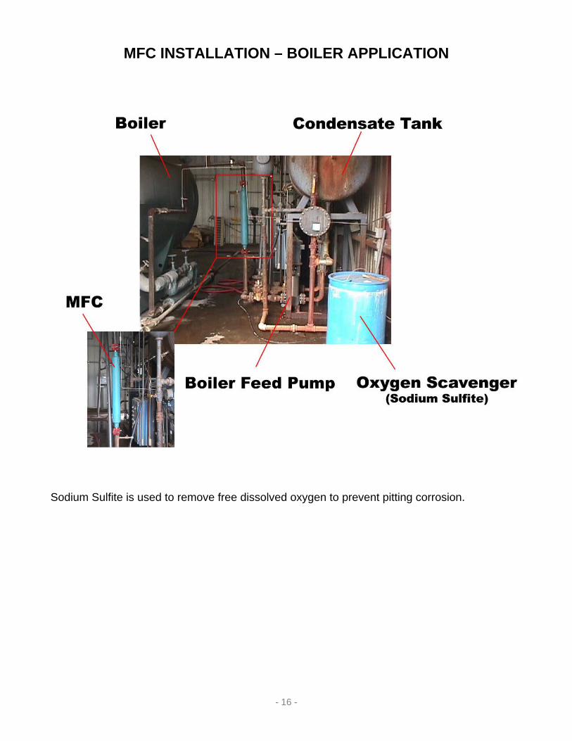
WELL INFORMATION SHEET
Co. Name: ___________________________ Well No.: ____________ Pumping: ____________ Attn: ___________________________ Field: ____________ Flowing: ____________
Address: ___________________________ Location: ____________ Gas Lift: ____________ ___________________________ Perf. Depth: ____________ ___________________________
Phone: ___________________________ Production Tube Fax: ___________________________ Size-Wt.-Thread
Email: ___________________________Seating Nipple
PUMP DATA Type-Make-Model A.PI. Pump Type: _______________ � Cup � Mechanical
Pump Plunger Diameter: _______________Actual Length of Pump: _______________ Seating Nipple
# of Strokes per Minute: _______________ Min. ID Other Pump Description: _______________
Anchor Type: � Top � Bottom Depth of Pump Or Seating Nipple
OPTIONAL ATTACHMENTS � OIL WATER OR SCALE ANALYSIS FLUID DATA � WELL COMPLETION DRAWINGS TOTAL FLUID/DAY OIL: WATER: � PAST PRODUCTION RECORDS A.P.I. GRAVITY: � OIL SAMPLE CU. FT. GAS/DAY: � WATER SAMPLE APPROX. BOTTOM HOLE TEMP: � SCALE SAMPLE WELL HEAD TEMP: � POUR POINT � WAX CONTENT GENERAL INFORMATION LOCATION OF INITIAL DEPOSITION:
FOR ALGAE-X USE ____________ Ft. ____________ Mts. DESCRIPTION OF DEPOSIT:
DATE INSTALLED: _______Inorganic – Type of Scale _________________________ TOOL TYPE: _______Organic: SN# � Wax � Asphaltene � Wax Emulsion
PRESENT TREATMENTS: � Thermal � Chemical � Mechanical TREATMENT FREQUENCY: TREATMENT COSTS ANNUALIZE: OTHER PROBLEMS:
IMPORTANT All tools are custom made to perform in a specific well or application. The information requested above is critical to the specifications of the tools. All representation, warranties or guarantees regarding the performance of the tool are made and based on the application of the tool in the above set forth conditions and environment. Algae-X is not responsible for nor warrants the performance of the tool under any conditions or environment other than those set forth above. By execution of this order form, Purchaser warrants that he/she has reviewed all information above and same is true and correct for the required application.
SIGNATURE DATE
- 22 -