COMMERCIAL HVAC PACKAGED EQUIPMENT Split...
81
Copyright © Carrier Corp. 2005 COMMERCIAL HVAC PACKAGED EQUIPMENT Split Systems Technical Development Program PRESENTED BY: Ray Chow Sigler
Transcript of COMMERCIAL HVAC PACKAGED EQUIPMENT Split...

Copyright © Carrier Corp. 2005
COMMERCIAL HVACPACKAGED EQUIPMENT
Split Systems
Technical Development Program
PRESENTED BY:
Ray Chow
Sigler

Copyright © Carrier Corp. 2005
Section 7 Summary
Section 6 Installation
Section 5 Controls
Section 4 Accessories
Section 3 System Components
Section 2 System Basics
Section 1 Introduction
Menu

Copyright © Carrier Corp. 2005
SECTION 1
Introduction
SPLIT SYSTEMS

Copyright © Carrier Corp. 2005
Objectives• Identify applications that utilize
the strengths of split systems
• Identify the components of split systems
• Understand the impact codes have onsystem application and selection
• Compare the differences in outdoorand indoor unit types
• Understand key installation issues
Section 1 – Introduction
Copyright © Carrier Corp. 2005
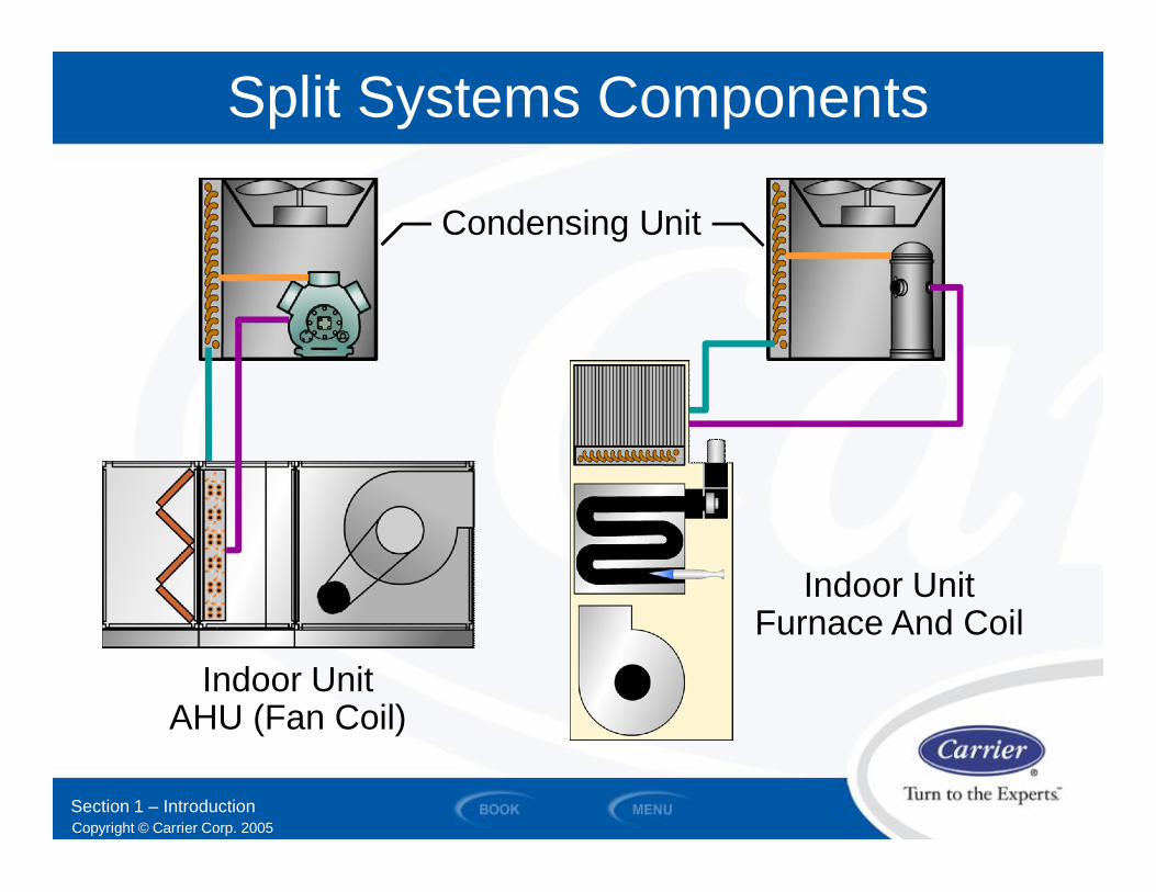
Split Systems Components
Section 1 – Introduction
Condensing Unit
Indoor UnitAHU (Fan Coil)
Indoor UnitFurnace And Coil

Copyright © Carrier Corp. 2005
Split Systems
• Residential to large commercial
• ¾ to 120+ tons
• Applications– Cooling only– Cooling with heat– Heat pump– Furnace with coil
• Utilize packaged products in an applied manner
Section 1 – Introduction

Copyright © Carrier Corp. 2005
• ARI has categories for air, evaporative or water-cooled• Plus 4 ARI heat pump categories (not shown)
• 5 ARI cooling split system categories
ARI System Classification
FanEvapCompCond
Single Package
Split Systems
Section 1 – Introduction
FanEvapComp
Cond+
RemoteCondenser
Cond+Fan
EvapHeat
Comp
Year RoundRemote Condenser
EvapCompCond+
Condensing Unitwith Coil
EvapCompCond+
Fan
Condensing Unitwith Coil + Fan
Cond+EvapHeat Comp
Fan
Year Round Condensing Unitwith Coil + Fan

Copyright © Carrier Corp. 2005
SECTION 2
System Basics
SPLIT SYSTEMS

Copyright © Carrier Corp. 2005
Liquid LineWarm-Temp., High-Pressure Liquid
Suction LineLow-Temp., Low-Pressure Vapor
FilterDrier
Indoor Unit
Outdoor Unit
Split System Basics
SightGlass
Liquid LineSolenoid Valve
Section 2 – System Basics

Copyright © Carrier Corp. 2005
Why Use a Split System?
Flexibility• Aesthetics
• Duct design
• Performance
• Zoning
Section 2 – System Basics

Copyright © Carrier Corp. 2005
• Mix and match indoor and outdoor units
• Closely match load requirements
• Use only manufacturer’sapproved combinations
Flexibility
10-ton condensing unit12½-ton AHU
10-ton AHU
OR
Section 2 – System Basics

Copyright © Carrier Corp. 2005
Residential & Duct Free Systems
Section 2 – System Basics

Copyright © Carrier Corp. 2005
Condensing units include:• Controls
• Compressors
• Condenser Coil
Condensing Units
Section 2 – System Basics

Copyright © Carrier Corp. 2005
Typical Condensing Units
Section 2 – System Basics

Copyright © Carrier Corp. 2005
Typical Indoor Unit
Cased Evaporator Coils Packaged AHU
Central Station AHU
Section 2 – System Basics

Copyright © Carrier Corp. 2005
Heat Pump System
Outdoor Unit• Condenser in cooling• Evaporator in heating
Indoor Unit• Evaporator in cooling• Condenser in heating
Section 2 – System Basics

Copyright © Carrier Corp. 2005
Refrigerant Circuits
Single Circuit
Dual Circuit
Section 2 – System Basics

Copyright © Carrier Corp. 2005
Indoor Unit – Refrigerant Circuits
Section 2 – System Basics
Single Circuit
TXV
LIQUIDLINE
Distributor
LIQUIDLINE
TXV
Filter Drier
Solenoid
Distributor
Dual Circuit

Copyright © Carrier Corp. 2005
ARI Standards
Section 2 – System Basics
Standard #
210/240
340/360
365
Applies to
Unitary Air Conditioners
Air Source UnitaryHeat Pumps (Air-Cooled)
Unitary Air Conditioners
Air Source UnitaryHeat Pumps (Air-Cooled)
Air ConditioningCondensing Units
Capacity Range
<65,000 Btuh
<65,000 Btuh
65,000 to <250,000 Btuh
65,000 to <250,000 Btuh
>135,000 to <250,000 Btuh

Copyright © Carrier Corp. 2005
EER
)()(
WattsInputPowerTotalBtuhCapacityEER =
11.2EER25.9290EER
kW3.1)(22.8MBtuh290EER
(Watts)InputPowerTotal(Btuh)CapacityEER
=
=
+=
=
Example 25-ton condensing unit @ ARI conditions
Section 2 – System Basics

Copyright © Carrier Corp. 2005
Net vs. Gross Capacity
HeatIFMCapacityGrossCapacityNet
InputPowerTotal(Btuh)CapacityNetEERSystem
-=
=
Section 2 – System Basics

Copyright © Carrier Corp. 2005
BHP Required
Interpolate to derive bhp for 0.44 in. wg
bhp @ 0.44 in. wg = 4.00 bhp
AHU Size Airflowcfm
External Static Pressure (in. wg)0.0 0.2 0.4 0.6
rpm bhp rpm bhp rpm bhp rpm bhp028 10,000 615 3.12 641 3.36 692 3.87 743 4.41
Section 2 – System Basics

Copyright © Carrier Corp. 2005
Btuh274,12Watts
Btuh3.414Watts3,595
Watts3,595HeatIFM
0.83746)(4.00HeatIFM
EfficiencyMotor746)(bhpHeatIFM
=*
=
*=
*=
IFM Heat
Section 2 – System Basics

Copyright © Carrier Corp. 2005
Net Capacity
Net Capacity = Gross Capacity – IFM Heat
Net Capacity = 294 – IFM Heat
Net Capacity = 282 MBtuh
Section 2 – System Basics

Copyright © Carrier Corp. 2005
Total Power Input
Now calculate Total Power Inputusing data from previous slides
( )EfficiencyMotor
746bhpmotorperpowerOFM *=
Section 2 – System Basics
kW29.5InputPowerTotalkW3.1kW3.6kW22.8InputPowerTotal
powerODFpowerIFMpowerCompressorInputPowerTotal
=++=
++=

Copyright © Carrier Corp. 2005
9.6EERSystem
kW29.5MBtuh282EERSystem
InputPowerTotalCapacityCoolingNetEERSystem
=
=
=
System EER
System EER for the 25-ton example system:
Section 2 – System Basics

Copyright © Carrier Corp. 2005
SEER
Applies to:– Single phase power only– Capacity less than 60 MBtuh
Calculated at three conditions and cycle test:– 80/67° F return air, 95° F outdoor air– 80/67° F return air, 82° F outdoor air– 80/57° F return air, 82° F outdoor air– 80/57° F cycle test, 82° F outdoor air
Requires laboratory testing and is not calculated in the field.
Section 2 – System Basics

Copyright © Carrier Corp. 2005
FOR ALL 3 Æ AND WATER-COOLED UNITS ANDAIR-COOLED UNITS ABOVE 60 MBH CAPACITY
• Evaluate equipment efficiency at less than full capacity
• Applicable only to equipment withmore than one stage of capacity
• Weighted average of EERat each capacity step
• Equipment with greater number of capacity steps can moreclosely match the load requirements of the space
• Unless equipment is always operated at 100%capacity, a higher IPLV is preferred
IPLV
Section 2 – System Basics
PARTLOADFACTORCURVE

Copyright © Carrier Corp. 2005
Coefficient of Performance
• Applies to heat pumps that operate on 3-phase power only
• Measures efficiency while operating in the heating mode
• A higher COP indicates a more efficient heat pump
)()(
WattsInputPowerTotalWattsCapacityNetCOP =
Section 2 – System Basics

Copyright © Carrier Corp. 2005
HSPF:• Applies to heat pumps that operate on single phase power
and have a cooling capacity of < 5.5 tons only
• Is similar to SEER in that it measures the seasonallyadjusted efficiency of a heat pump
• Accounts for defrost and required electric heat
• A higher HSPF is a more efficient heat pump
Heating Seasonal Performance Factor
Section 2 – System Basics

Copyright © Carrier Corp. 2005
Energy Codes
Section 2 – System Basics
Many codes rely on ASHRAE 90.1 thatsets minimum efficiency requirements.
Air-Cooled Split System Requirements• Performance requirements
< 65,000 Btuh 10.0 SEER 1Ø≥ 65,000 – < 135,000 Btuh 10.3 EER≥ 135,000 – < 240,000 Btuh 9.7 EER≥ 240,000 – < 760,000 Btuh 9.5 EER / 9.7 IPLV≥ 760,000 Btuh 9.2 EER / 9.4 IPLV
• Control requirements• Motor hp limits• Economizer requirements• Heat pump requirements

Copyright © Carrier Corp. 2005
IAQ and Sustainability
Section 2 – System Basics
• IAQ – ASHRAE 62– Limits maximum humidity to less than 65%– Indoor unit condensate control– Indoor unit ventilation capability
• Sustainable Design – LEED™– Require meeting ASHRAE 90.1 efficiency
and ASHRAE 62 IAQ features– Optimized energy performance and IAQ
Split System mix and matches providebetter humidity control and flexibility
to meet these requirements
Copyright © Carrier Corp. 2005
SECTION 3
System Components
SPLIT SYSTEMS

Copyright © Carrier Corp. 2005
Rules of Thumb
Section 3 – System Components
Rules of Thumb are considered to be guidelines only• Airflow:
- 400 cfm per nominal ton- Range of 300 to 500 cfm per ton- Today, 350 cfm per ton may be more
appropriate• Mix and Match:
- Nominal and one size up,sometimes one size down,others depend (consult the manufacturer)
• Line Length:- Keep them at 100 ft or less

Copyright © Carrier Corp. 2005
Operating LimitsCooling only equipment:Maximum outdoor air temperatureMinimum return air temperatureMaximum return air temperatureSaturated suction temperature rangeMaximum discharge superheatMinimum discharge superheat
Typical saturated suction temperature rangefor air conditioning duty is 40 to 50° F
Heat Pumps:Maximum outdoor air operating temperature in heatingMinimum outdoor air operating temperature in heating
115° F55° F95° F
25 to 55° F275° F60° F
75° F–20° F
Section 3 – System Components

Copyright © Carrier Corp. 2005
Outdoor Units
Residential1½ to 5 ton
Duct Free¾ to 5 ton
Commercial6 to 100+ ton
Section 3 – System Components

Copyright © Carrier Corp. 2005
Semi-Hermetic Compressor
• Repairable
• CapacityControl
Section 3 – System Components
CylinderUnloader

Copyright © Carrier Corp. 2005
Multiple Compressors
Dual Semi-HermeticReciprocating
Dual Scroll
Section 3 – System Components

Copyright © Carrier Corp. 2005
Multiple Condensing Units
Dual Circuit Indoor Unit
1st Stage Condensing Unit
2nd Stage Condensing Unit
Section 3 – System Components

Copyright © Carrier Corp. 2005
Hot Gas Bypass
• Protects system in low load conditions• Prevents coil icing• Injects hot gas at indoor unit• Activates at minimum step of cooling only
Condenser
Evaporator
LiquidSolenoid
Valve
Hot GasSolenoid
Valve
Compressor
DischargeBypass Valve
Filter Drier
SightGlass
TXV
Section 3 – System Components

Copyright © Carrier Corp. 2005
Alternative Condensing Unit SolutionsWater-Cooled
Condensing Unit
To indoor coil
Compressor
From indoor coil
Triple-Split
Condenser
Section 3 – System Components

Copyright © Carrier Corp. 2005
Heat Pump System
Heating Mode
Accumulator
Compressor
4-WayValve
Bi-flowFilter Drier
OU
TDO
OR
CO
IL IND
OO
RC
OIL
Accurator
TXV with bypassCheck Valves
Section 3 – System Components
Bi-flowTXV

Copyright © Carrier Corp. 2005
Cooling Mode
Heat Pump System
Accumulator
Compressor
4-WayValve
FilterDrier
OU
TDO
OR
CO
IL IND
OO
RC
OIL
Accurator
Bi-flowTXV
Check Valves
Section 3 – System Components
TXV with bypass
Bi-flowFilter Drier

Copyright © Carrier Corp. 2005
Indoor Unit – Air Handler
6 to 30 ton Packaged AHUwith limited options
Central Station AHU
Section 3 – System Components
Copyright © Carrier Corp. 2005
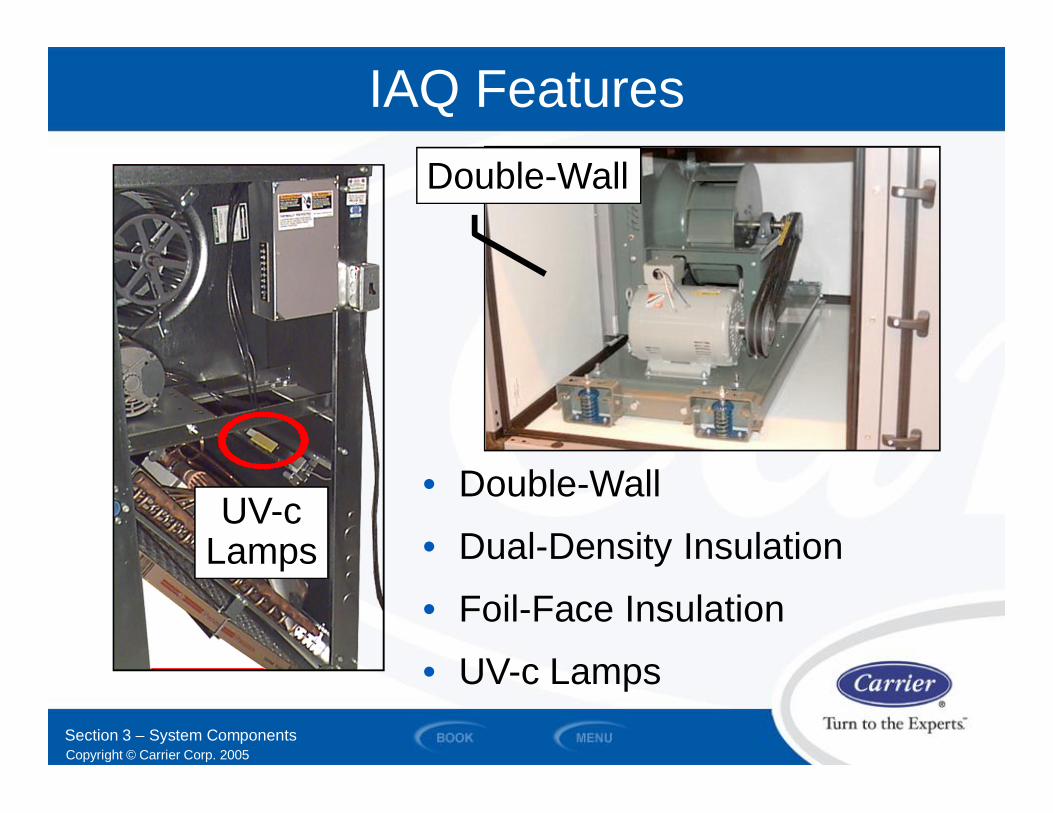
IAQ Features
• Double-Wall
• Dual-Density Insulation
• Foil-Face Insulation
• UV-c Lamps
Double-Wall
Section 3 – System Components
UV-cLamps

Copyright © Carrier Corp. 2005
Constant Volume AHU
• Variable pitch pulleyis set at required airflowat first unit start-up
• Fan then operates ata constant speed
Section 3 – System Components

Copyright © Carrier Corp. 2005
VAV Application
VAV Terminal
Inlet Guide VanesVFD
COIL
MOTOR
SUPPLYFAN
Section 3 – System Components

Copyright © Carrier Corp. 2005
VAV Requirements
Indoor Unit• At least two circuits• Equipped with capacity control valve(s)
LIQUIDLINE
FilterDrier
CapacityControl
Solenoid TXVDistributor
SightGlass
Section 3 – System Components

Copyright © Carrier Corp. 2005
VAV Requirements
Outdoor Unit• Multiple stages of capacity
• Electric control of capacity stages
• Suction line accumulators
• Interface with VAV controller
Section 3 – System Components

Copyright © Carrier Corp. 2005
VAV Controller
• Typically controls discharge air temperature
• Controls:– Compressors– Stages of capacity– Fans
Section 3 – System Components

Copyright © Carrier Corp. 2005
Cased Evaporator Coils
Installed in duct“A” coil design, installed
on twinned furnaces
Section 3 – System Components

Copyright © Carrier Corp. 2005
Residential Coils
Cased Uncased
Section 3 – System Components

Copyright © Carrier Corp. 2005
SECTION 4
Accessories
SPLIT SYSTEMS

Copyright © Carrier Corp. 2005
Economizer
• “Free Cooling”
• Control types– Dry bulb– Enthalpy– Differential enthalpy– CO2
• Demand controlledventilation (DCV)
Return air
Outdoor air
Section 4 – Accessories

Copyright © Carrier Corp. 2005
Heating AccessoriesHot Water or
Steam Coil onPackaged AHU
Electric HeatAccessory onPackaged AHU
Section 4 – Accessories

Copyright © Carrier Corp. 2005
Furnaces
Horizontal Furnace
Twinned Furnaces
Section 4 – Accessories
with downstreamcooling coil

Copyright © Carrier Corp. 2005
Accessories
Plenum
Return AirGrille
Subbase
CondensateDrain
Section 4 – Accessories

Copyright © Carrier Corp. 2005
SECTION 5
Controls
SPLIT SYSTEMS

Copyright © Carrier Corp. 2005
Controls - ThermostatSimple control requirements:
• Indoor fan
• Outdoor fan(s)
• Compressor(s)
• Liquid line solenoid
Section 5 – Controls

Copyright © Carrier Corp. 2005
• Y2 initiates 2nd stage cooling
Two-Stage Thermostat• Y1 initiates 1st stage cooling
Section 5 – Controls

Copyright © Carrier Corp. 2005
Capacity Control Solenoid Valve
Section 5 – Controls
• Y2 opens the liquid linesolenoid valve
• Y1 initiates 1st stage coolingAND opens the liquid linesolenoid valve

Copyright © Carrier Corp. 2005
DDC Control
Section 5 – Controls
User Interface
Copyright © Carrier Corp. 2005
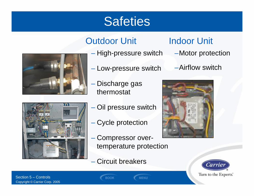
SafetiesOutdoor Unit
– High-pressure switch
– Low-pressure switch
– Discharge gasthermostat
– Oil pressure switch
– Cycle protection
– Compressor over-temperature protection
– Circuit breakers
Section 5 – Controls
Indoor Unit–Motor protection
–Airflow switch

Copyright © Carrier Corp. 2005
Low Ambient Control
• Proper operation of expansion device at low outdoor temps
• Minimum outdoor air operating temperature
• Maintain minimum SCT
• Low ambient controller – OFM motor controller
MINIMUM OUTDOOR-AIR OPERATINGTEMPERATURE
UNIT38AR
CONDTEMP
(F)
MINIMUMOUTDOOR TEMP
(F)
Std.With
Motormaster®Control
Z007Z008Z012
808080
353535
-20S012 80
803535
D012 80 35
Section 5 – Controls
Motormaster® Control

Copyright © Carrier Corp. 2005
Fan Cycling Pressure Switch
• Turn off #2 OFM motorwhen SCT falls too low
• DO NOT cycle #1 OFM motor on/off becausea speed control device is required
OFM Motor
Intermediate SeasonSCT Control Device
#2 #1
Section 5 – Controls
Copyright © Carrier Corp. 2005
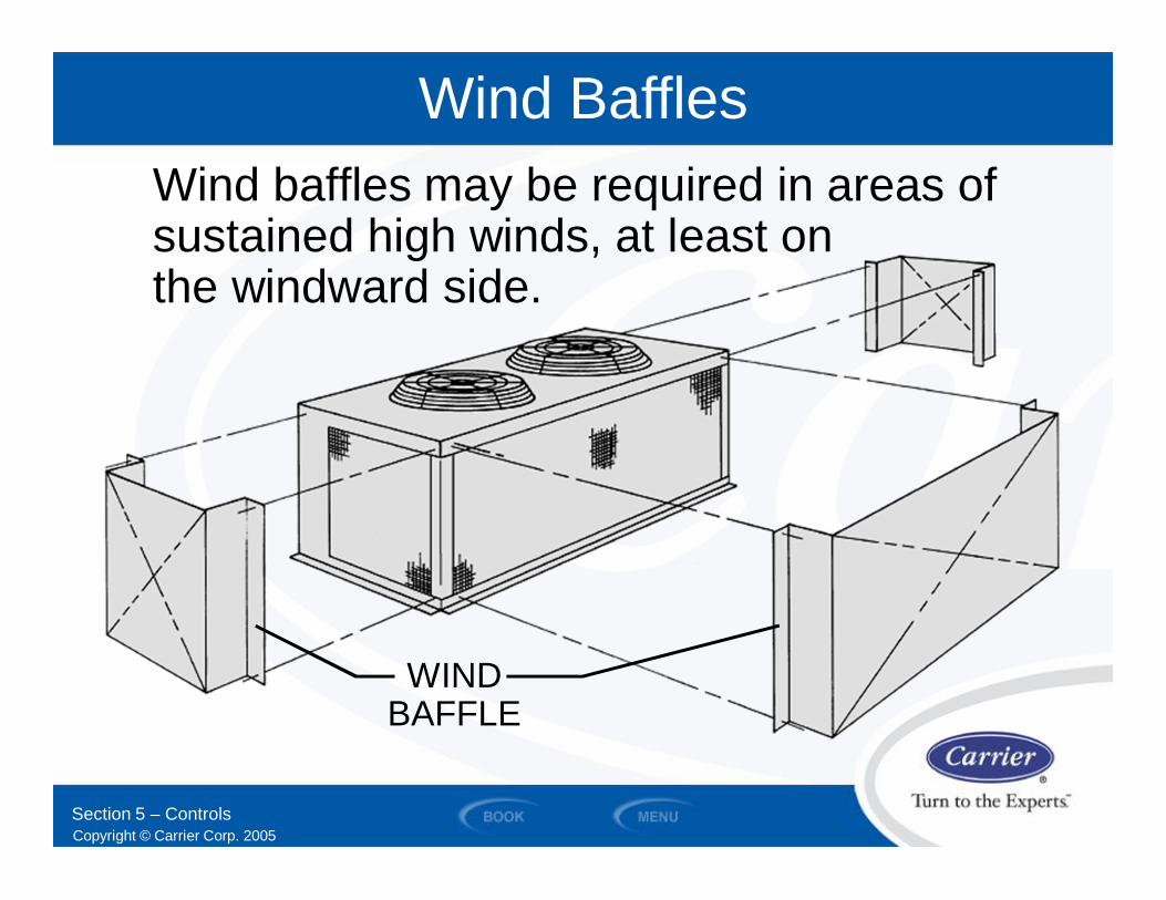
Wind BafflesWind baffles may be required in areas ofsustained high winds, at least onthe windward side.
Section 5 – Controls
WINDBAFFLE

Copyright © Carrier Corp. 2005
SECTION 6
Installation
SPLIT SYSTEMS

Copyright © Carrier Corp. 2005
Power SupplyMinimum Circuit Ampacity (MCA)
determines required wire size
MCA = (1.25 * Current of largest motor)+ Sum of all other loads
MCA of a condensing unit = (1.25 * RLA of compressor)+ (FLA of OFM motors+ Control amps)
MCA of indoor unit with electric heat = (1.25 * FLA of largest motor)+ (1.25 * FLA of electric heater)+ Sum of all other loads
Section 6 – Installation

Copyright © Carrier Corp. 2005
MOCPDefines MAXIMUM size ofovercurrent protective device
A smaller device may be used, if nuisance trips are not a problem
MOCP = (2.25 * Current of largest motor) + Sum of all other loads
Round down to the next lower standard rating,but not lower than the MCA value
Section 6 – Installation

Copyright © Carrier Corp. 2005
• Fuse or Circuit Breaker
Protective Device
Section 6 – Installation
Usage defined by code and availability
• HACR Breaker

Copyright © Carrier Corp. 2005
CONDENSINGUNIT
Disconnect• Located within “line of sight”
• Field-installed or factory-supplied
• Fused or non-fused
Section 6 – Installation
Field-installed disconnect
Factory-installed disconnect
FUSEDDISCONNECTSWITCH

Copyright © Carrier Corp. 2005
Installation
• Consult manufacturer’s instructions
• Locate indoor and outdoor unitsas close together as possible
• Keep refrigerant pipingas short as possible
• Provide adequate clearancefor service access and airflow
Section 6 – Installation

Copyright © Carrier Corp. 2005
Sound
• Understand sound power (both indoor and outdoor)• Utilize sound reduction accessories when available• Consider the effect of sound when recommending
unit location• Isolate and support refrigerant tubing
Section 6 – Installation

Copyright © Carrier Corp. 2005
ElevationLIQUID LINE – 38AKS012-024 UNITS
UNIT38AKS
MAXALLOW.
LIFT(ft)
LIQUID LINE
Max Allow.Pressure
Drop(psi)
Max Allow.TempLoss(°F)
012014016024
65678287
7 2
NOTE: Data above is for units at 45° F saturatedsuction and 95° F entering air.
Section 6 – Installation
LIQUID LIFT

Copyright © Carrier Corp. 2005
Suction Riser
• Refrigerant velocity insuction riser must behigh enough to entraincompressor oil with therefrigerant
• Double suction riser orreduced diameter risermay be required
• Consult manufacturer’srecommendations
Section 6 – Installation

Copyright © Carrier Corp. 2005
Maximum Length of Refrigerant Piping
• Piping length depends on the application
• Heat pumps – 100 linear feet
• Consult manufacturer’s recommendations
Section 6 – Installation

Copyright © Carrier Corp. 2005
Long Lines Require:1. Liquid line solenoid valve(s)
LONG LINE = 75 LINEAR FEET OR LONGER
Lift vs. Run
Long Line Applications
Section 6 – Installation
LIFT
2. Suction line accumulator(s)

Copyright © Carrier Corp. 2005
SECTION 7
Summary
SPLIT SYSTEMS

Copyright © Carrier Corp. 2005
Summary
Section 8 – Summary
• Identified applications that utilize thestrengths of split systems
• Identified the components of split systems
• Discussed the impact that codes haveon system application and selection
• Compared the differences inoutdoor and indoor unit types
• Reviewed key installation issues

Copyright © Carrier Corp. 2005
Work Session 1
Work Session 1
SPLIT SYSTEMS
Work Session 1Multiple-choice questions may have more than one correct answer; identify all correct selections.
1. A typical commercial split system includes _______.
a) an indoor unit only c) an indoor and an out unit
b) a compressor, an indoor fan, an evapora- d) a compressor, an indoor fan, an evapo-tor and condenser as one or more rator and condenser as a packagesections
2. True or False? All commercial split systems are at least dual circuit. __________
3. True or False? Net capacity will always be greater than gross capacity. __________
4. SEER applies to _____
a. units which are cooling and heat single phase units under 65,000 Btuh

Copyright © Carrier Corp. 2005
Technical Development Program
Thank YouThis completes the presentation.
TDP-634 Split SystemsArtwork from Symbol Library used by permission ofSoftware Toolboxwww.softwaretoolbox.com/symbols