Commercial Horizontal & Vertical Packaged Water-Source ...
36
Heat Controller, Inc. • 1900 Wellworth Ave. • Jackson, MI 49203 • (517)787-2100 • www.heatcontroller.com ENGINEERING DESIGN GUIDE Commercial Horizontal & Vertical Packaged Water-Source Heat Pumps: HBH/V Compact
Transcript of Commercial Horizontal & Vertical Packaged Water-Source ...
Heat Controller, Inc. • 1900 Wellworth Ave. • Jackson, MI 49203 • (517)787-2100 • www.heatcontroller.com
ENGINEERINGDESIGN GUIDE
Commercial Horizontal & VerticalPackaged Water-Source Heat Pumps:
HBH/V Compact

Engineering Design Guide HBH/V SERIES Heat Controller, Inc.
2
Unit Features ........................................................................................................................................................ 3
Selection Procedure ..........................................................................................................................................4-5
HB Series Nomenclature ...................................................................................................................................... 6
Performance Data - ARI/ASHRAE/ISO 13256-1 .................................................................................................. 7
Performance Data Selection Notes ...................................................................................................................... 8
Performance Data - HBH/V 006 ........................................................................................................................... 9
Performance Data - HBH/V 009 ......................................................................................................................... 10
Performance Data - HBH/V 012 ......................................................................................................................... 11
Performance Data - HBH/V 015 ......................................................................................................................... 12
Performance Data - HBH/V 018 ......................................................................................................................... 13
Performance Data - HBH/V 024 ......................................................................................................................... 14
Performance Data - HBH/V 030 ......................................................................................................................... 15
Performance Data - HBH/V 036 ......................................................................................................................... 16
Performance Data - HBH/V 042 ......................................................................................................................... 17
Performance Data - HBH/V 048 ......................................................................................................................... 18
Performance Data - HBH/V 060 ......................................................................................................................... 19
Air Flow Correction Tables .................................................................................................................................. 20
Antifreeze Correction Table ................................................................................................................................ 21
Blower Performance Data - Standard Unit ......................................................................................................... 22
Blower Performance Data - High Static .............................................................................................................. 23
Physical Data ...................................................................................................................................................... 24
HB - Horizontal Dimensional Data .................................................................................................................25-26
HB - Vertical Upfl ow Dimensional Data .........................................................................................................27-28
Corner Weights for HB Series Units ................................................................................................................... 29
Electrical Data - Standard Unit ........................................................................................................................... 30
Electrical Data - High Static Blower .................................................................................................................... 31
HB Series Wiring Diagram Matrix ....................................................................................................................... 32
Typical Wiring Diagram Single Phase HB Units With CXM Controller ............................................................... 33
Typical Wiring Diagram Three Phase 208/230V HB Units With CXM Controller ................................................ 34
Typical Wiring Diagram Three Phase 460/575V HB Units with CXM Controller ................................................ 35
Table of Contents

Engineering Design Guide HBH/V SERIES Heat Controller, Inc.
3
Unit Features
HB SeriesThe HBH/V Series exceeds ASHRAE 90.1 effi ciencies, and uses R-410A zero ozone depletion refrigerant, making it an extremely environmentally-friendly option. HBH/V is eligible for additional LEED™ (Leadership in Energy and Environmental Design) points because of the “green” technology design. With one of the smallest cabinets in the industry, the HBH/V will easily fi t into tight spaces. Designed to be backward compatible with thousands of older water-source heat pumps.
Available in sizes from 1/2 ton (1.76 kW) through 5 tons (17.6 kW) with multiple cabinet options (vertical upfl ow and horizontal) the HBH/V offers a wide range of units for most any installation. The HBH/V has an extended range refrigerant circuit, capable of geothermal ground loop applications (with optional extended range insulation) as well as boiler-tower water loop applications. Standard features include: Copeland scroll compressors (rotary for size 018 and below), microprocessor controls, galvanized steel cabinet, galvanized steel with epoxy powder painted drain pan and sound absorbing air handler insulation.
Heat Controller’s exclusive double isolation compressor mounting system makes the HBH/V the quietest unit on the market. Compressors are mounted via rubber vibration isolators to a heavy gauge mounting plate, which is further isolated from the cabinet base with rubber grommets for maximized vibration/sound attenuation. The easy access control box and large access panels make installing and maintaining the unit easier than other water-source heat pumps currently in production, proving that a small unit can be easy to service.
The HBH/V Series is full of options, such as an e-coated air coil. Optional high static fan motor expands the operating range and helps overcome some of the challenges associated with ductwork for retrofi t installations. A Cupro-Nickel water-coil and sound absorbing mute package are options that make a great unit even better.
The HBH/V Series Water-Source Heat Pumps are designed to meet the challenges of today’s HVAC demands with one of the most innovative products available on the market.
Unit Features• Sizes 006 (1/2 ton, 1.76 kW) through 060 (5 tons, 17.6 kW)• R-410A refrigerant• Exceeds ASHRAE 90.1 effi ciencies• Galvanized steel construction• Epoxy powder painted galvanized steel drain pan• Sound absorbing glass fi ber insulation• Unique double isolation compressor mounting via
vibration isolating rubber grommets for quiet operation• Insulated divider and separate compressor/air handler
compartments• Copeland scroll compressors (rotary for size 018 and
below)• TXV metering device • Microprocessor controls standard• Field convertible discharge air arrangement for horizontal
units• PSC three-speed fan motor• Internally trapped condensate drain line (vertical units
only)• Unit Performance Sentinel performance monitoring
system• Eight Safeties Standard• Extended range (20 to 120°F, -6.7 to 48.9°C) capable• High static blowers available• Cupro-Nickel water-coil available• Sound absorbing UltraQuiet package available

Engineering Design Guide HBH/V SERIES Heat Controller, Inc.
4
Reference Calculations
BTUH = BTU (British Thermal Unit) per hour CFM = airfl ow, cubic feet/minute COP = coeffi cient of performance = BTUH output/BTUH input DB = dry bulb temperature (°F) EAT = entering air temperature, Fahrenheit (dry bulb/wet bulb) EER = energy effi ciency ratio = BTUH output/Watt input MPT = male pipe thread ESP = external static pressure (inches w.g.) EWT = entering water temperature GPM = water fl ow in U.S. gallons/minute HE = total heat of extraction, BTUH HC = air heating capacity, BTUH HR = total heat of rejection, BTUH
HWC = hot water generator (desuperheater) capacity, Mbtuh FPT = female pipe thread KW = total power unit input, kilowatts LAT = leaving air temperature, °F LC = latent cooling capacity, BTUH LWT = leaving water temperature, °FMBTUH = 1000 BTU per hour S/T = sensible to total cooling ratio SC = sensible cooling capacity, BTUH TC = total cooling capacity, BTUH WB = wet bulb temperature (°F) WPD = waterside pressure drop (psi & ft. of hd.)
Conversion Table - to convert inch-pound (English) to S-I (Metric)
Legend and Glossary of Abbreviations
Selection Procedure
Air Flow Water Flow Ext Static Pressure Water Pressure Drop
Airflow (L/s) = CFM x 0.472 Water Flow (L/s) = gpm x 0.0631 ESP (Pa) = ESP (in of wg) x 249 PD (kPa) = PD (ft of hd) x 2.99
LWT = EWT -HE
GPM x 500
LAT = EAT +HC
CFM x1.08
LWT = EWT +HR
GPM x 500
LAT (DB) = EAT (DB) - SCCFM x1.08
LC = TC - SC
S/T =SCTC
Heating Cooling

Engineering Design Guide HBH/V SERIES Heat Controller, Inc.
5
Step 1 Determine the actual heating and cooling loads at the desired dry bulb and wet bulb conditions.
Step 2 Obtain the following de sign parameters: Entering water temperature, water fl ow rate in GPM, air fl ow in CFM, water fl ow pressure drop and design wet and dry bulb temperatures. Air fl ow CFM should be between 300 and 450 CFM per ton. Unit water pressure drop should be kept as close as possible to each other to make water balancing easier. Go to the ap pro pri ate tables and fi nd the proper indicated water fl ow and water tem per a ture.
Step 3 Select a unit based on total and sensible cooling
conditions. Select a unit which is closest to, but no larger than, the actual cooling load.
Step 4 Enter tables at the design water fl ow and water temperature. Read the total and sensible cooling capacities (Note: interpolation is per mis si ble, ex trap o la tion is not).
Step 5 Read the heating capacity. If it exceeds the design criteria it is acceptable. It is quite normal for Water-Source Heat Pumps to be selected on cooling capacity only since the heating output is usually greater than the cooling capacity.
Step 6 Determine the correction factors associated with the variable factors of dry bulb, wet bulb and air fl ow.
Corrected Total Cooling = tabulated total cooling x wet bulb correction x air fl ow
correction Corrected Sensible Cooling = tabulated sensible cooling x dry bulb correction x air fl ow
correction
Step 7 Compare the corrected capacities to the load re quire ments. Normally if the capacities are within 10% of the loads, the equipment is ac cept able. It is better to undersize than oversize, as undersizing improves humidity control, reduces sound levels and extends the life of the equip ment.
Step 8 When completed, calculate water temperature rise and assess the selection. If the units selected are not within 10% of the load cal cu la tions, then review what effect chang ing the GPM, water temperature and/or air fl ow and air tem per a ture would have on the corrected capacities. If the desired capacity cannot be achieved, select the next larger or smaller unit and repeat the procedure. Remember, when in doubt, undersize slightly for best performance.
Example Equipment Selection For Cool ing
Step 1 Load Determination:Assume we have determined that the appropriate cooling load at the desired dry bulb 80°F and wet bulb 65°F con di tions is as follows:
Total Cooling ...................................... 23,700 BTUHSensible Cooling ................................. 16,500 BTUHEntering Air Temp .... 80°F Dry Bulb / 65°F Wet Bulb
Step 2 Design Conditions:Similarly, we have also obtained the following design pa ram e ters:
Entering Water Temp ....................................... 90°FWater Flow (Based upon 10°F rise in temp.) 6.0 GPMAir Flow .................................................... 800 CFM
Step 3, 4 & 5 HP Selection:After making our preliminary selection (HBH/V 024), we enter the tables at design water fl ow and water tem per a ture and read Total Cooling, Sens. Cooling and Heat of Rej. ca pac i ties:
Total Cooling ....................................... 23,400 BTUHSensible Cooling ................................. 17,500 BTUHHeat of Rejection ................................ 30,200 BTUH
Step 6 & 7 Entering Air and Airfl ow Corrections:Next, we determine our correction factors.
Table Ent Air Air Flow Cor rect edCorrected Total Cooling = 23,400 x 0.9681 x 1.0050 = 22,767Corrected Sens Cooling = 17,500 x 1.1213 x 0.9820 = 19,270Corrected Heat of Reject = 30,200 x 0.9747 x 1.0434 = 30,713
Step 8 Water Temperature Rise Calculation & As sess ment:
Actual Temperature Rise 10.2°F
When we compare the Corrected Total Cooling and Corrected Sensible Cooling fi gures with our load re quire ments stated in Step 1, we discover that our selection is within +/- 10% of our sensible load requirement. Fur ther more, we see that our Cor rect ed Total Cooling fi gure is within 1,000 Btuh the actual in di cat ed load.
Selection Procedure
Engineering Design Guide HBH/V SERIES Heat Controller, Inc.
6
H B H A0 3 6 C3 3 0 A L B1 2 3 4 5 6 7 8 9 10 11 12 13 14
HB = HEAT CONTROLLER COMPACT 410AMODEL TYPE
H = HORIZONTAL (NON PAINTED)CONFIGURATION
V = VERTICAL (PAINTED POLAR ICE)
UNIT SIZE
018 024 030 036042 048 060
REVISION LEVELA = CURRENT REVISION
VOLTAGE
C = CXMCONTROLS
CABINET INSULATION
0 = NONEFUTURE USE
A = Copper Water Coil w/E-Coated Air CoilHEAT EXCHANGER OPTIONSC = Copper Water Coil w/Non-Coated Air Coil
L = LEFT RETURNRETURN AIR OPTIONSR = RIGHT RETURNF = FRONT RETURN, VERTICAL
B = BACK DISCHARGE, HORIZONTAL ONLYSUPPLY AIR OPTIONSY = BACK DISCHARGE, HIGH STATIC HORIZONTALT = TOP DISCHARGE, VERTICAL ONLYV = TOP DISCHARGE, HIGH STATIC VERTICAL S = STRAIGHT DISCHARGE, HORIZONTAL ONLYZ = STRAIGHT DISCHARGE, HIGH STATIC HORIZONTAL
J = Cupro-Nickel Water Coil w/E-Coated Air CoilN = Cupro-Nickel Water Coil w/Non-Coated Air Coil
015
1 = 208-230/60/18 = 265/60/13 = 208-230/60/34 = 460/60/35 = 575/60/3
1 = EXTENDED RANGE2 = EXTENDED RANGE WITH ULTRA QUIET3 = STANDARD RANGE4 = STANDARD RANGE WITH ULTRA QUIETC = STANDARD RANGE, COOLING ONLY, VERTICAL UNITS
3 = DISCHARGE PRESSURE WATER REGULATING VALVE (COOLING ONLY)
V = LEFT RETURN, S.S DRAIN PANW = RIGHT RETURN, S.S DRAIN PANZ = FRONT RETURN, S.S. DRAIN PAN
006 009 012
HBH & HBV Model Structure
Basic Unit Description:
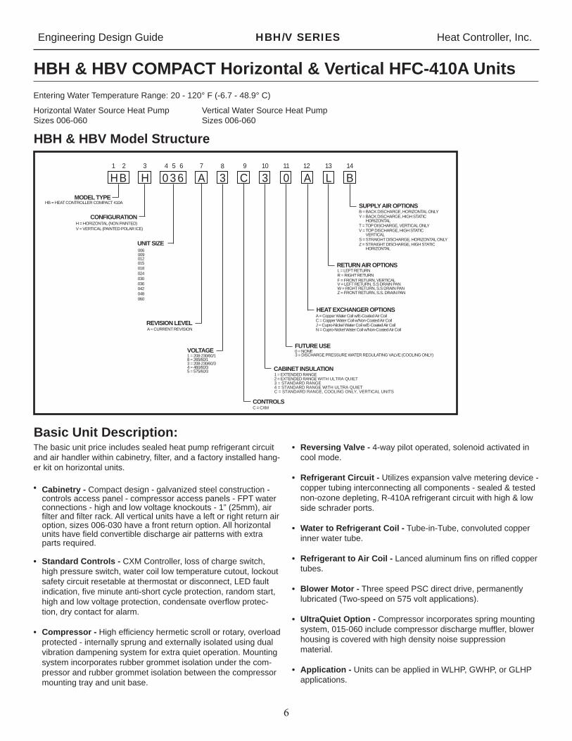
HBH & HBV COMPACT Horizontal & Vertical HFC-410A Units
The basic unit price includes sealed heat pump refrigerant circuit and air handler within cabinetry, fi lter, and a factory installed hang-er kit on horizontal units.
• Cabinetry - Compact design - galvanized steel construction - controls access panel - compressor access panels - FPT water connections - high and low voltage knockouts - 1” (25mm), air fi lter and fi lter rack. All vertical units have a left or right return air option, sizes 006-030 have a front return option. All horizontal units have fi eld convertible discharge air patterns with extra parts required.
• Standard Controls - CXM Controller, loss of charge switch, high pressure switch, water coil low temperature cutout, lockout safety circuit resetable at thermostat or disconnect, LED fault indication, fi ve minute anti-short cycle protection, random start, high and low voltage protection, condensate overfl ow protec-tion, dry contact for alarm.
• Compressor - High effi ciency hermetic scroll or rotary, overload protected - internally sprung and externally isolated using dual vibration dampening system for extra quiet operation. Mounting system incorporates rubber grommet isolation under the com-pressor and rubber grommet isolation between the compressor mounting tray and unit base.
• Reversing Valve - 4-way pilot operated, solenoid activated in cool mode.
• Refrigerant Circuit - Utilizes expansion valve metering device - copper tubing interconnecting all components - sealed & tested non-ozone depleting, R-410A refrigerant circuit with high & low side schrader ports.
• Water to Refrigerant Coil - Tube-in-Tube, convoluted copper inner water tube.
• Refrigerant to Air Coil - Lanced aluminum fi ns on rifl ed copper tubes.
• Blower Motor - Three speed PSC direct drive, permanently lubricated (Two-speed on 575 volt applications).
• UltraQuiet Option - Compressor incorporates spring mounting system, 015-060 include compressor discharge muffl er, blower housing is covered with high density noise suppression material.
• Application - Units can be applied in WLHP, GWHP, or GLHP applications.
Entering Water Temperature Range: 20 - 120° F (-6.7 - 48.9° C)
Horizontal Water Source Heat Pump Vertical Water Source Heat PumpSizes 006-060 Sizes 006-060
skanalas
Typewritten Text
(009 thru 030 vertical only)
skanalas
Typewritten Text

Engineering Design Guide HBH/V SERIES Heat Controller, Inc.
7
Performance DataAHRI/ASHRAE/ISO 13256-1
ASHRAE/AHRI/ISO 13256-1 English (I-P) Units
ASHRAE/AHRI/ISO 13256-1 Metric (S-I) Units
Model
Water Loop Heat Pump Ground Water Heat Pump Ground Loop Heat Pump
Cooling 86°F Heating 68°F Cooling 59°F Heating 50°F Cooling 77°F Heating 32°F
CapacityBtuh
EERBtuh/W
CapacityBtuh COP Capacity
BtuhEER
Btuh/WCapacity
Btuh COP CapacityBtuh
EERBtuh/W
CapacityBtuh COP
HB-006 5,800 13.2 7,500 4.7 6,900 21.1 6,200 4.0 6,200 15.4 4,900 3.4
HB-009 8,800 13.4 11,600 4.2 10,100 21.0 9,800 3.9 9,300 15.7 7,900 3.4
HB-012 11,700 13.5 15,200 4.3 13,700 20.8 12,500 3.8 12,000 14.9 9,900 3.2
HB-015 14,500 15.4 17,300 5.0 16,800 24.5 14,400 4.4 15,000 17.2 11,100 3.6
HB-018 17,300 14.3 21,500 5.0 20,600 24.2 17,200 4.4 18,400 16.3 13,900 3.4
HB-024 23,700 13.4 28,500 4.7 26,700 20.9 24,000 4.1 24,900 15.4 18,500 3.3
HB-030 28,100 13.4 35,100 4.6 31,700 20.1 29,600 4.1 28,900 15.1 23,400 3.4
HB-036 34,500 13.5 45,200 4.4 38,700 20.7 37,500 4.0 35,300 14.9 29,600 3.3
HB-041 36,500 13.1 45,700 4.2 41,400 19.7 38,000 3.7 38,000 14.8 30,100 3.1
HB-042 40,100 13.1 52,700 4.3 45,900 19.6 44,000 3.8 40,500 14.4 34,300 3.2
HB-048 47,700 13.3 55,900 4.7 54,300 20.5 46,500 4.1 49,000 14.7 36,400 3.4
HB-060 59,400 13.4 77,000 4.3 66,600 19.9 64,000 3.8 60,100 14.8 50,500 3.1
Cooling capacities based upon 80.6°F DB, 66.2°F WB entering air temperatureHeating capacities based upon 68°F DB, 59°F WB entering air temperatureAll ratings based upon operation at lower voltage of dual voltage rated models
Model
Water Loop Heat Pump Ground Water Heat Pump Ground Loop Heat Pump
Cooling 30°C Heating 20°C Cooling 15°C Heating 10°C Cooling 25°C Heating 0°C
CapacitykW
EERW/W
CapacitykW COP Capacity
kWEERW/W
CapacitykW COP Capacity
kWEERW/W
CapacitykW COP
HB-006 1.70 3.9 2.20 4.7 2.02 6.2 1.82 4.0 1.82 4.5 1.44 3.4
HB-009 2.58 3.9 3.40 4.2 2.96 6.2 2.87 3.9 2.72 4.6 2.31 3.4
HB-012 3.43 4.0 4.45 4.3 4.01 6.1 3.66 3.8 3.52 4.4 2.90 3.2
HB-015 4.25 4.5 5.07 5.0 4.92 7.2 4.22 4.4 4.39 5.0 3.25 3.6
HB-018 5.07 4.2 6.30 5.0 6.04 7.1 5.04 4.4 5.39 4.8 4.07 3.4
HB-024 6.94 3.9 8.35 4.7 7.82 6.1 7.03 4.1 7.30 4.5 5.42 3.3
HB-030 8.23 3.9 10.28 4.6 9.29 5.9 8.67 4.1 8.47 4.4 6.86 3.4
HB-036 10.11 4.0 13.24 4.4 11.34 6.1 10.99 4.0 10.34 4.4 8.67 3.3
HB-041 10.69 3.8 13.39 4.2 12.13 5.8 11.13 3.7 11.13 4.3 8.82 3.1
HB-042 11.75 3.8 15.44 4.3 13.45 5.7 12.89 3.8 11.87 4.2 10.05 3.2
HB-048 13.98 3.9 16.38 4.7 15.91 6.0 13.62 4.1 14.36 4.3 10.67 3.4
HB-060 17.40 3.9 22.56 4.3 19.51 5.8 18.75 3.8 17.61 4.3 14.80 3.1
Cooling capacities based upon 27°C DB, 19°C WB entering air temperatureHeating capacities based upon 20°C DB, 15°C WB entering air temperatureAll ratings based upon operation at lower voltage of dual voltage rated models

Engineering Design Guide HBH/V SERIES Heat Controller, Inc.
8
Performance DataSelection Notes
For operation in the shaded area when water is used in lieu of an anti-freeze solution, the LWT (Leaving Water Temperature) must be calculated. Flow must be maintained to a level such that the LWT is maintained above 40°F [4.4*C] when the JW3 jumper is not clipped (see example below). This is due to the potential of the refrigerant temperature being as low as 32°F [0°C] with 40°F [4.4°C] LWT, which may lead to a nuisance cutout due to the activation of the Low Temperature Protection. JW3 should never be clipped for standard range equipment or systems without antifreeze.
Example:
At 50°F EWT (Entering Water Temperature) and 2.25 gpm/ton, a 3 ton unit has a HE of 27,300 Btuh. To calculate LWT, rearrange the formula for HE as follows:
HE = TD x GPM x 500, where HE = Heat of Extraction (Btuh); TD = temperature difference (EWT - LWT) and GPM = U.S. Gallons per Minute.
TD = HE / (GPM x 500)
TD = 27,300 / (6.75 x 500)
TD = 8°F
LWT = EWT - TD
LWT = 50 - 8 = 42°F
In this example, as long as the EWT does not fall below 50°F, the system will operate as designed. For EWTs below 50°F, higher fl ow rates will be required (open loop systems, for example, require at least 2 gpm/ton when EWT is below 50°F).
0 0 0 710 11.6 1.05 8.2 85.1 3.25 0 0 0 825 11.7 1.02 8.4 83.2 3.38
3 0.58 24.1 38.3 710 13.6 1.09 10.1 87.8 3.66 5 0.59 24.4 38.3 825 13.8 1.06 10.3 85.5 3.81 3 0.57 24.3 39.2 710 14.2 1.09 10.7 88.5 3.81 5 0.58 24.7 39.2 825 14.4 1.06 10.9 86.1 3.97 2 0.56 24.4 39.8 710 14.4 1.09 10.9 88.8 3.86 5 0.57 24.7 39.8 825 14.6 1.06 11.1 86.3 4.02 6 0.65 25.1 35.3 710 16.1 1.15 12.3 90.9 4.08 8 0.66 25.5 35.3 825 16.2 1.12 12.6 88.2 4.25 5 0.61 25.2 37.9 710 16.7 1.15 13.0 91.8 4.25 8 0.62 25.5 37.9 825 16.9 1.12 13.3 89.0 4.42 5 0.6 25.2 38.3 710 16.9 1.16 13.2 92.1 4.30 8 0.61 25.6 38.3 825 17.1 1.12 13.5 89.2 4.47 8 0.74 25.2 30.7 710 18.3 1.18 14.5 93.9 4.56 0 0.75 25.6 30.7 825 18.5 1.14 14.8 90.8 4.75 7 0.69 25.3 33.4 710 19.1 1.18 15.2 94.8 4.73 0 0.70 25.6 33.4 825 19.3 1.15 15.5 91.6 4.93 7 0.67 25.3 34.1 710 19.3 1.18 15.4 95.1 4.78 0 0.68 25.6 34.1 825 19.5 1.15 15.7 91.9 4.98 0 0.85 24.8 25.9 710 20.4 1.21 16.5 96.6 4.93 3 0.86 25.1 25.9 825 20.6 1.18 16.8 93.2 5.13 9 0.78 25.1 28.6 710 21.2 1.22 17.3 97.7 5.10 2 0.80 25.4 28.6 825 21.5 1.18 17.6 94.1 5.31 9 0.77 25.1 29.4 710 21.5 1.22 17.5 98.0 5.15 1 0.78 25.5 29.4 825 21.7 1.19 17.8 94.3 5.36 2 0.97 24.0 21.4 710 22.4 1.23 18.4 99.2 5.35 4 0 98 24 3 21 4 825 22 7 1 19 18 8 95 4 5 57
AT 80/67°F Heating - EAT 70°F/Tot tio kW HR EER Airfl ow
CFM HC kW HE LAT COP
recommended

Engineering Design Guide HBH/V SERIES Heat Controller, Inc.
9
Performance DataHBH/V 006
Performance capacities shown in thousands of Btuh220 CFM Nominal (Rated) Airfl ow
Interpolation is permissible; extrapolation is not.All entering air conditions are 80°F DB and 67°F WB in cooling, and 70°F DB in heating. AHRI/ISO certifi ed conditions are 80.6°F DB and 66.2°F WB in cooling and 68°F DB in heating. Table does not refl ect fan or pump power corrections for AHRI/ISO conditions.All performance is based upon the lower voltage of dual voltage rated units.Performance stated is at the rated power supply; performance may vary as the power supply varies from the rated.Operation below 40°F EWT is based upon a 15% methanol antifreeze solution. Operation below 60°F EWT requires optional insulated water/refrigerant circuit.See performance correction tables for operating conditions other than those listed above.See Performance Data Selection Notes for operation in the shaded areas.
EWT °F GPM
WPD Cooling - EAT 80/67°F Heating - EAT 70°F
PSI FT Airfl ow CFM TC SC Sens/Tot
Ratio kW HR EER Airfl ow CFM HC kW HE LAT COP
20 1.5 1.7 4.0Operation not recommended
170 4.3 0.49 2.7 93.3 2.61.5 1.7 4.0 225 4.4 0.44 2.9 88.0 2.9
30
0.8 0.5 1.2 170 7.4 4.2 0.57 0.28 8.4 26.4 170 4.6 0.50 3.0 95.2 2.70.8 0.5 1.2 225 7.7 4.8 0.62 0.29 8.7 26.4 225 4.7 0.45 3.2 89.5 3.11.1 0.8 1.8 170 7.4 4.1 0.55 0.26 8.3 28.5 170 4.8 0.51 3.2 96.2 2.81.1 0.8 1.8 225 7.7 4.6 0.60 0.27 8.6 28.5 225 4.9 0.46 3.4 90.3 3.21.5 1.3 2.9 170 7.3 4.0 0.54 0.25 8.2 29.2 170 4.9 0.51 3.2 96.8 2.81.5 1.3 2.9 225 7.6 4.5 0.59 0.26 8.5 29.2 225 5.0 0.46 3.5 90.7 3.2
40
0.8 0.4 0.9 170 7.3 4.3 0.59 0.31 8.3 23.2 170 5.3 0.52 3.6 98.8 3.00.8 0.4 0.9 225 7.6 4.8 0.64 0.33 8.7 23.2 225 5.4 0.47 3.8 92.3 3.41.1 0.6 1.4 170 7.4 4.2 0.57 0.29 8.4 25.8 170 5.5 0.53 3.8 100.2 3.11.1 0.6 1.4 225 7.7 4.8 0.62 0.30 8.7 25.8 225 5.7 0.47 4.1 93.3 3.51.5 1.0 2.4 170 7.4 4.2 0.56 0.28 8.4 26.9 170 5.7 0.53 3.9 100.9 3.11.5 1.0 2.4 225 7.7 4.7 0.61 0.29 8.7 26.9 225 5.8 0.48 4.2 93.9 3.6
50
0.8 0.3 0.8 170 6.9 4.2 0.61 0.35 8.1 19.9 170 6.0 0.54 4.2 102.7 3.30.8 0.3 0.8 225 7.2 4.8 0.66 0.36 8.5 19.9 225 6.1 0.48 4.5 95.3 3.71.1 0.5 1.2 170 7.2 4.3 0.59 0.32 8.3 22.5 170 6.3 0.55 4.5 104.4 3.41.1 0.5 1.2 225 7.5 4.8 0.64 0.33 8.6 22.5 225 6.5 0.49 4.8 96.6 3.91.5 0.9 2.0 170 7.3 4.3 0.58 0.31 8.3 23.8 170 6.5 0.55 4.6 105.4 3.41.5 0.9 2.0 225 7.6 4.8 0.63 0.32 8.7 23.8 225 6.7 0.50 5.0 97.4 3.9
60
0.8 0.3 0.6 170 6.5 4.1 0.63 0.39 7.9 16.8 170 6.7 0.56 4.9 106.7 3.50.8 0.3 0.6 225 6.8 4.7 0.69 0.40 8.2 16.8 225 6.9 0.50 5.2 98.4 4.01.1 0.5 1.0 170 6.9 4.2 0.61 0.36 8.1 19.1 170 7.1 0.57 5.2 108.6 3.71.1 0.5 1.0 225 7.1 4.8 0.67 0.37 8.4 19.1 225 7.3 0.51 5.5 99.9 4.21.5 0.8 1.8 170 7.0 4.2 0.61 0.34 8.2 20.4 170 7.3 0.57 5.3 109.7 3.71.5 0.8 1.8 225 7.3 4.8 0.66 0.36 8.5 20.4 225 7.5 0.51 5.7 100.7 4.3
70
0.8 0.2 0.5 170 6.0 4.0 0.66 0.43 7.5 14.0 170 7.4 0.58 5.5 110.5 3.80.8 0.2 0.5 225 6.3 4.5 0.72 0.45 7.8 14.0 225 7.6 0.52 5.9 101.4 4.31.1 0.4 0.9 170 6.4 4.1 0.64 0.40 7.8 16.0 170 7.8 0.58 5.8 112.4 3.91.1 0.4 0.9 225 6.7 4.6 0.70 0.42 8.1 16.0 225 8.0 0.53 6.2 102.8 4.51.5 0.7 1.6 170 6.6 4.1 0.63 0.38 7.9 17.1 170 8.0 0.59 5.9 113.4 4.01.5 0.7 1.6 225 6.8 4.7 0.69 0.40 8.2 17.1 225 8.2 0.53 6.4 103.6 4.5
80
0.8 0.2 0.5 170 5.6 3.8 0.68 0.47 7.2 12.0 170 7.9 0.59 5.9 113.2 4.00.8 0.2 0.5 225 5.8 4.3 0.74 0.49 7.5 12.0 225 8.1 0.53 6.3 103.5 4.51.1 0.4 0.8 170 5.9 3.9 0.67 0.45 7.4 13.2 170 8.3 0.60 6.3 115.4 4.11.1 0.4 0.8 225 6.1 4.4 0.73 0.46 7.7 13.2 225 8.5 0.54 6.7 105.1 4.61.5 0.6 1.5 170 6.2 4.0 0.65 0.42 7.6 14.7 170 8.4 0.60 6.3 115.7 4.11.5 0.6 1.5 225 6.4 4.6 0.71 0.44 7.9 14.7 225 8.6 0.54 6.7 105.3 4.6
85
0.8 0.2 0.5 170 5.3 3.7 0.70 0.50 7.0 10.7 170 8.2 0.60 6.2 114.7 4.00.8 0.2 0.5 225 5.5 4.2 0.76 0.52 7.3 10.7 225 8.4 0.50 6.6 104.6 4.61.1 0.3 0.8 170 5.6 3.8 0.68 0.47 7.2 11.9 170 8.5 0.60 6.4 116.2 4.11.1 0.3 0.8 225 5.8 4.3 0.74 0.49 7.5 11.9 225 8.7 0.50 6.8 105.8 4.71.5 0.6 1.4 170 5.8 3.9 0.67 0.45 7.4 13.1 170 8.5 0.60 6.4 116.4 4.11.5 0.6 1.4 225 6.1 4.4 0.73 0.47 7.7 13.1 225 8.7 0.50 6.8 105.9 4.7
90
0.8 0.2 0.4 170 5.0 3.6 0.72 0.53 6.7 9.4 170 8.5 0.61 6.4 116.3 4.10.8 0.2 0.4 225 5.2 4.1 0.79 0.55 7.0 9.4 225 8.7 0.55 6.8 105.8 4.71.1 0.3 0.7 170 5.3 3.7 0.70 0.49 7.0 10.7 170 8.6 0.62 6.5 117.0 4.11.1 0.3 0.7 225 5.5 4.2 0.76 0.52 7.3 10.7 225 8.8 0.55 7.0 106.4 4.71.5 0.6 1.3 170 5.5 3.8 0.69 0.48 7.1 11.5 170 8.7 0.62 6.5 117.1 4.11.5 0.6 1.3 225 5.7 4.3 0.75 0.50 7.4 11.5 225 8.9 0.56 7.0 106.5 4.7
100
0.8 0.2 0.4 170 4.4 3.4 0.76 0.58 6.4 7.6
Operation not recommended
0.8 0.2 0.4 225 4.6 3.8 0.83 0.60 6.6 7.61.1 0.3 0.7 170 4.7 3.5 0.74 0.55 6.6 8.71.1 0.3 0.7 225 4.9 4.0 0.80 0.57 6.9 8.71.5 0.5 1.2 170 4.9 3.6 0.73 0.53 6.7 9.31.5 0.5 1.2 225 5.1 4.0 0.79 0.55 7.0 9.3
110
0.8 0.2 0.3 170 3.9 3.1 0.81 0.63 6.0 6.20.8 0.2 0.3 225 4.1 3.6 0.87 0.66 6.3 6.21.1 0.3 0.6 170 4.2 3.3 0.78 0.60 6.2 7.01.1 0.3 0.6 225 4.4 3.7 0.85 0.62 6.5 7.01.5 0.5 1.2 170 4.3 3.3 0.77 0.58 6.3 7.41.5 0.5 1.2 225 4.5 3.8 0.83 0.61 6.6 7.4
120
0.8 0.1 0.3 170 3.5 3.0 0.85 0.68 5.8 5.00.8 0.1 0.3 225 3.6 3.3 0.93 0.71 6.0 5.01.1 0.3 0.6 170 3.7 3.0 0.83 0.65 5.9 5.61.1 0.3 0.6 225 3.8 3.4 0.90 0.68 6.2 5.61.5 0.5 1.1 170 3.8 3.1 0.81 0.64 6.0 6.01.5 0.5 1.1 225 4.0 3.5 0.88 0.67 6.2 6.0

Engineering Design Guide HBH/V SERIES Heat Controller, Inc.
10
Performance DataHBH/V 009
Performance capacities shown in thousands of Btuh325 CFM Nominal (Rated) Airfl ow
Interpolation is permissible; extrapolation is not.All entering air conditions are 80°F DB and 67°F WB in cooling, and 70°F DB in heating. AHRI/ISO certifi ed conditions are 80.6°F DB and 66.2°F WB in cooling and 68°F DB in heating. Table does not refl ect fan or pump power corrections for AHRI/ISO conditions.All performance is based upon the lower voltage of dual voltage rated units.Performance stated is at the rated power supply; performance may vary as the power supply varies from the rated.Operation below 40°F EWT is based upon a 15% methanol antifreeze solution. Operation below 60°F EWT requires optional insulated water/refrigerant circuit.See performance correction tables for operating conditions other than those listed above.See Performance Data Selection Notes for operation in the shaded areas.
EWT °F GPM
WPD Cooling - EAT 80/67°F Heating - EAT 70°F
PSI FT Airfl ow CFM TC SC Sens/Tot
Ratio kW HR EER Airfl ow CFM HC kW HE LAT COP
20 2.3 4.5 10.5Operation not recommended
250 6.5 0.73 4.2 94.2 2.62.3 4.5 10.5 330 6.7 0.66 4.4 88.8 3.0
30
1.1 1.3 3.0 250 10.2 6.0 0.59 0.39 11.6 26.6 250 7.1 0.74 4.7 96.3 2.81.1 1.3 3.0 330 10.7 6.8 0.64 0.40 12.0 26.6 330 7.3 0.67 5.0 90.4 3.21.7 1.9 4.4 250 10.5 6.0 0.57 0.36 11.7 29.5 250 7.4 0.75 4.9 97.4 2.91.7 1.9 4.4 330 10.9 6.8 0.62 0.37 12.2 29.5 330 7.6 0.67 5.3 91.2 3.32.3 3.5 8.1 250 10.6 6.0 0.56 0.34 11.8 31.1 250 7.5 0.75 5.1 97.9 2.92.3 3.5 8.1 330 11.0 6.8 0.61 0.36 12.3 31.1 330 7.7 0.68 5.4 91.7 3.4
40
1.1 0.9 2.0 250 9.9 6.0 0.61 0.43 11.3 22.8 250 8.0 0.76 5.5 99.8 3.11.1 0.9 2.0 330 10.3 6.8 0.66 0.45 11.8 22.8 330 8.2 0.69 5.9 93.1 3.51.7 1.5 3.5 250 10.1 6.0 0.59 0.40 11.5 25.4 250 8.4 0.77 5.8 101.1 3.21.7 1.5 3.5 330 10.5 6.8 0.64 0.41 12.0 25.4 330 8.6 0.69 6.2 94.1 3.62.3 3.0 6.8 250 10.3 6.0 0.59 0.38 11.6 26.8 250 8.6 0.78 6.0 101.8 3.22.3 3.0 6.8 330 10.7 6.8 0.64 0.40 12.0 26.9 330 8.8 0.70 6.4 94.7 3.7
50
1.1 0.6 1.5 250 9.4 6.0 0.63 0.48 11.1 19.5 250 9.0 0.79 6.4 103.3 3.41.1 0.6 1.5 330 9.8 6.7 0.69 0.50 11.6 19.5 330 9.2 0.71 6.8 95.8 3.81.7 1.3 2.9 250 9.7 6.0 0.62 0.45 11.3 21.7 250 9.4 0.80 6.7 104.8 3.51.7 1.3 2.9 330 10.1 6.8 0.67 0.47 11.7 21.7 330 9.6 0.72 7.2 97.0 3.92.3 2.6 6.0 250 9.9 6.0 0.61 0.43 11.3 23.0 250 9.6 0.80 6.9 105.6 3.52.3 2.6 6.0 330 10.3 6.8 0.66 0.45 11.8 23.0 330 9.8 0.72 7.4 97.6 4.0
60
1.1 0.5 1.2 250 9.0 5.9 0.65 0.54 10.8 16.5 250 9.9 0.81 7.2 106.8 3.61.1 0.5 1.2 330 9.4 6.7 0.71 0.57 11.3 16.5 330 10.2 0.73 7.7 98.5 4.11.7 1.1 2.5 250 9.3 5.9 0.64 0.50 11.0 18.5 250 10.4 0.82 7.6 108.4 3.71.7 1.1 2.5 330 9.7 6.7 0.69 0.52 11.5 18.5 330 10.6 0.74 8.1 99.8 4.22.3 2.3 5.4 250 9.5 6.0 0.63 0.48 11.1 19.6 250 10.6 0.83 7.8 109.3 3.72.3 2.3 5.4 330 9.8 6.7 0.69 0.50 11.6 19.6 330 10.9 0.75 8.3 100.5 4.3
70
1.1 0.4 0.9 250 8.5 5.8 0.68 0.61 10.6 14.0 250 10.8 0.84 8.0 110.1 3.81.1 0.4 0.9 330 8.8 6.5 0.74 0.63 11.0 14.0 330 11.1 0.75 8.5 101.1 4.31.7 1.0 2.3 250 8.8 5.8 0.66 0.56 10.7 15.6 250 11.3 0.85 8.4 111.9 3.91.7 1.0 2.3 330 9.2 6.6 0.72 0.59 11.2 15.6 330 11.6 0.77 9.0 102.5 4.42.3 2.1 4.9 250 9.1 5.9 0.65 0.53 10.9 17.1 250 11.4 0.85 8.5 112.1 3.92.3 2.1 4.9 330 9.5 6.7 0.71 0.55 11.3 17.1 330 11.6 0.77 9.0 102.7 4.4
80
1.1 0.3 0.8 250 8.0 5.6 0.70 0.67 10.3 11.8 250 11.7 0.87 8.7 113.3 4.01.1 0.3 0.8 330 8.3 6.3 0.77 0.70 10.7 11.8 330 12.0 0.78 9.3 103.6 4.51.7 0.9 2.1 250 8.3 5.7 0.69 0.63 10.5 13.2 250 12.2 0.88 9.1 115.1 4.01.7 0.9 2.1 330 8.6 6.5 0.75 0.66 10.9 13.2 330 12.5 0.79 9.8 105.0 4.62.3 2.0 4.6 250 8.6 5.8 0.67 0.59 10.6 14.4 250 12.2 0.88 9.2 115.4 4.12.3 2.0 4.6 330 8.9 6.5 0.73 0.62 11.1 14.4 330 12.5 0.79 9.8 105.2 4.6
85
1.1 0.3 0.7 250 7.7 5.5 0.71 0.70 10.1 11.0 250 12.0 0.88 9.0 114.5 4.01.1 0.3 0.7 330 8.0 6.2 0.78 0.73 10.5 11.0 330 12.3 0.80 9.6 104.6 4.61.7 0.9 2.0 250 8.0 5.6 0.70 0.67 10.3 12.1 250 12.6 0.90 9.5 116.5 4.11.7 0.9 2.0 330 8.4 6.4 0.76 0.69 10.7 12.1 330 12.9 0.80 10.1 106.1 4.72.3 1.9 4.4 250 8.3 5.7 0.69 0.63 10.5 13.3 250 12.6 0.90 9.5 116.8 4.12.3 1.9 4.4 330 8.7 6.5 0.75 0.65 10.9 13.3 330 12.9 0.80 10.2 106.3 4.7
90
1.1 0.3 0.6 250 7.5 5.4 0.72 0.73 10.0 10.2 250 12.3 0.89 9.3 115.7 4.11.1 0.3 0.6 330 7.8 6.2 0.79 0.76 10.4 10.2 330 12.6 0.80 9.9 105.5 4.61.7 0.8 1.9 250 7.7 5.5 0.71 0.70 10.1 11.1 250 12.9 0.91 9.8 117.9 4.21.7 0.8 1.9 330 8.1 6.3 0.78 0.73 10.6 11.1 330 13.3 0.82 10.5 107.2 4.82.3 1.8 4.3 250 8.0 5.6 0.70 0.66 10.3 12.1 250 13.0 0.91 9.9 118.2 4.22.3 1.8 4.3 330 8.4 6.4 0.76 0.69 10.7 12.1 330 13.3 0.82 10.5 107.4 4.8
100
1.1 0.2 0.6 250 6.8 5.1 0.76 0.82 9.6 8.2
Operation not recommended
1.1 0.2 0.6 330 7.0 5.8 0.82 0.86 10.0 8.21.7 0.8 1.7 250 7.1 5.3 0.74 0.78 9.8 9.21.7 0.8 1.7 330 7.4 6.0 0.81 0.81 10.2 9.22.3 1.7 4.0 250 7.3 5.4 0.73 0.75 9.9 9.72.3 1.7 4.0 330 7.6 6.1 0.80 0.78 10.3 9.7
110
1.1 0.2 0.5 250 6.1 4.8 0.79 0.90 9.2 6.81.1 0.2 0.5 330 6.3 5.4 0.85 0.94 9.5 6.81.7 0.7 1.6 250 6.5 5.0 0.77 0.86 9.4 7.61.7 0.7 1.6 330 6.8 5.6 0.84 0.89 9.8 7.62.3 1.6 3.8 250 6.7 5.1 0.76 0.83 9.5 8.02.3 1.6 3.8 330 7.0 5.8 0.83 0.87 9.9 8.0
120
1.1 0.2 0.4 250 5.4 4.4 0.82 0.98 8.7 5.51.1 0.2 0.4 330 5.6 5.0 0.89 1.02 9.1 5.51.7 0.7 1.6 250 5.8 4.6 0.80 0.94 9.0 6.21.7 0.7 1.6 330 6.0 5.2 0.87 0.98 9.4 6.22.3 1.6 3.6 250 6.0 4.7 0.79 0.91 9.1 6.52.3 1.6 3.6 330 6.2 5.4 0.86 0.95 9.5 6.5

Engineering Design Guide HBH/V SERIES Heat Controller, Inc.
11
Performance DataHBH/V 012
400 CFM Nominal (Rated) Airfl ow
Interpolation is permissible; extrapolation is not.All entering air conditions are 80°F DB and 67°F WB in cooling, and 70°F DB in heating. AHRI/ISO certifi ed conditions are 80.6°F DB and 66.2°F WB in cooling and 68°F DB in heating. Table does not refl ect fan or pump power corrections for AHRI/ISO conditions.All performance is based upon the lower voltage of dual voltage rated units.Performance stated is at the rated power supply; performance may vary as the power supply varies from the rated.Operation below 40°F EWT is based upon a 15% methanol antifreeze solution. Operation below 60°F EWT requires optional insulated water/refrigerant circuit.See performance correction tables for operating conditions other than those listed above.See Performance Data Selection Notes for operation in the shaded areas.
EWT°F
GPMWPD Cooling - EAT 80/67°F Heating - EAT 70°F
PSI FT Airfl owCFM TC SC Sens/Tot
Ratio kW HR EER Airfl owCFM HC kW HE LAT COP
20 Operation not recommended
30
40
50
60
70
80
85
90
100
Operation not recommended110
120
3.0 8.5 19.6 300 300 8.5 0.98 5.3 96.2 2.5 3.0 8.5 19.6 400 400 8.7 0.88 5.7 90.2 2.9 1.5 1.9 4.3 300 14.2 8.2 0.58 0.55 16.1 25.8 300 9.3 1.00 6.0 98.6 2.7 1.5 1.9 4.3 400 14.8 9.3 0.63 0.57 16.8 25.8 400 9.5 0.90 6.4 91.9 3.1 2.3 3.6 8.4 300 14.3 8.2 0.58 0.51 16.1 27.9 300 9.6 1.01 6.3 99.7 2.8 2.3 3.6 8.4 400 14.9 9.3 0.63 0.53 16.7 27.9 400 9.9 0.91 6.8 92.8 3.2 3.0 6.7 15.5 300 14.3 8.2 0.58 0.50 16.0 28.8 300 9.8 1.02 6.5 100.4 2.8 3.0 6.7 15.5 400 14.9 9.3 0.63 0.52 16.6 28.8 400 10.1 0.92 7.0 93.3 3.2 1.5 1.4 3.2 300 14.0 8.1 0.58 0.61 16.0 22.9 300 10.6 1.04 7.1 102.6 3.0 1.5 1.4 3.2 400 14.5 9.2 0.63 0.63 16.7 22.9 400 10.8 0.93 7.6 95.0 3.4 2.3 3.0 6.9 300 14.2 8.2 0.58 0.57 16.1 25.1 300 11.0 1.05 7.6 104.1 3.1 2.3 3.0 6.9 400 14.8 9.3 0.63 0.59 16.8 25.1 400 11.3 0.94 8.1 96.2 3.5 3.0 5.7 13.1 300 14.3 8.2 0.58 0.54 16.1 26.2 300 11.3 1.06 7.8 104.9 3.1 3.0 5.7 13.1 400 14.8 9.3 0.63 0.57 16.8 26.2 400 11.6 0.95 8.3 96.8 3.6 1.5 1.1 2.5 300 13.5 7.9 0.58 0.67 15.8 20.1 300 11.9 1.08 8.3 106.8 3.2 1.5 1.1 2.5 400 14.1 8.9 0.63 0.70 16.5 20.1 400 12.2 0.97 8.9 98.2 3.7 2.3 2.6 6.0 300 13.9 8.0 0.58 0.62 16.0 22.2 300 12.5 1.09 8.9 108.6 3.4 2.3 2.6 6.0 400 14.4 9.1 0.63 0.65 16.7 22.2 400 12.8 0.98 9.5 99.6 3.8 3.0 5.0 11.5 300 14.0 8.1 0.58 0.60 16.1 23.3 300 12.8 1.10 9.1 109.6 3.4 3.0 5.0 11.5 400 14.6 9.2 0.63 0.63 16.7 23.3 400 13.1 0.99 9.8 100.4 3.9 1.5 0.9 2.1 300 12.9 7.6 0.59 0.74 15.5 17.4 300 13.3 1.11 9.6 111.1 3.5 1.5 0.9 2.1 400 13.5 8.6 0.64 0.77 16.1 17.4 400 13.6 1.00 10.2 101.5 4.0 2.3 2.3 5.3 300 13.4 7.8 0.58 0.69 15.7 19.3 300 14.0 1.13 10.2 113.1 3.6 2.3 2.3 5.3 400 13.9 8.8 0.63 0.72 16.4 19.3 400 14.3 1.02 10.8 103.1 4.1 3.0 4.5 10.3 300 13.6 7.9 0.58 0.67 15.8 20.4 300 14.3 1.14 10.5 114.2 3.7 3.0 4.5 10.3 400 14.1 8.9 0.63 0.69 16.5 20.4 400 14.7 1.03 11.2 104.0 4.2 1.5 0.8 1.8 300 12.2 7.3 0.60 0.82 15.0 14.9 300 14.7 1.15 10.8 115.3 3.7 1.5 0.8 1.8 400 12.7 8.3 0.65 0.85 15.6 14.9 400 15.0 1.04 11.5 104.8 4.2 2.3 2.1 4.8 300 12.5 7.4 0.59 0.77 15.2 16.3 300 15.4 1.18 11.4 117.6 3.8 2.3 2.1 4.8 400 13.1 8.4 0.64 0.80 15.8 16.3 400 15.8 1.06 12.2 106.5 4.4 3.0 4.1 9.5 300 12.7 7.5 0.59 0.75 15.3 17.0 300 15.8 1.19 11.7 118.8 3.9 3.0 4.1 9.5 400 13.3 8.5 0.64 0.78 15.9 17.0 400 16.2 1.07 12.5 107.5 4.4 1.5 0.7 1.5 300 11.4 7.0 0.61 0.90 14.5 12.7 300 16.0 1.20 11.9 119.4 3.9 1.5 0.7 1.5 400 11.9 7.9 0.67 0.94 15.1 12.7 400 16.4 1.08 12.7 108.0 4.5 2.3 1.9 4.4 300 11.8 7.1 0.60 0.85 14.7 13.9 300 16.8 1.22 12.6 121.7 4.0 2.3 1.9 4.4 400 12.3 8.0 0.65 0.88 15.3 13.9 400 17.2 1.10 13.4 109.8 4.6 3.0 3.8 8.8 300 12.0 7.2 0.60 0.83 14.8 14.5 300 17.2 1.24 12.9 123.0 4.1 3.0 3.8 8.8 400 12.5 8.1 0.65 0.86 15.4 14.5 400 17.6 1.11 13.8 110.7 4.6 1.5 0.6 1.5 300 10.9 6.8 0.62 0.9 14.2 11.7 300 16.6 1.22 12.5 121.3 4.0 1.5 0.6 1.5 400 11.4 7.7 0.68 0.98 14.7 11.7 400 17.0 1.1 13.3 109.4 4.6 2.3 1.8 4.2 300 11.4 6.9 0.61 0.89 14.4 12.8 300 17.4 1.3 13.1 123.6 4.1 2.3 1.8 4.2 400 11.9 7.9 0.66 0.93 15.0 12.8 400 17.8 1.1 14.0 111.2 4.6 3.0 3.7 8.5 300 11.6 7.0 0.60 0.87 14.5 13.4 300 17.7 1.3 13.4 124.8 4.1 3.0 3.7 8.5 400 12.1 7.9 0.66 0.90 15.1 13.4 400 18.2 1.1 14.3 112.1 4.7 1.5 0.6 1.4 300 10.5 6.7 0.63 0.99 13.9 10.7 300 17.3 1.24 13.0 123.3 4.1 1.5 0.6 1.4 400 10.9 7.5 0.69 1.03 14.4 10.7 400 17.7 1.12 13.9 110.9 4.6 2.3 1.8 4.1 300 11.0 6.8 0.62 0.93 14.1 11.7 300 18.0 1.28 13.6 125.5 4.1 2.3 1.8 4.1 400 11.4 7.7 0.67 0.97 14.7 11.7 400 18.4 1.15 14.5 112.6 4.7 3.0 3.6 8.2 300 11.2 6.8 0.61 0.91 14.3 12.3 300 18.3 1.29 13.9 126.6 4.2 3.0 3.6 8.2 400 11.6 7.7 0.67 0.95 14.8 12.3 400 18.8 1.16 14.8 113.5 4.7 1.5 0.5 1.2 300 9.5 6.4 0.67 1.07 13.2 8.9 300 1.5 0.5 1.2 400 9.9 7.2 0.72 1.12 13.8 8.9 400 2.3 1.7 3.8 300 10.1 6.5 0.65 1.02 13.5 9.8 300 2.3 1.7 3.8 400 10.5 7.3 0.70 1.06 14.1 9.8 400 3.0 3.3 7.7 300 10.4 6.6 0.64 1.00 13.8 10.4 300 3.0 3.3 7.7 400 10.8 7.5 0.69 1.04 14.3 10.4 400 1.5 0.5 1.1 300 8.5 6.0 0.71 1.17 12.5 7.3 300 1.5 0.5 1.1 400 8.9 6.8 0.77 1.22 13.1 7.3 400 2.3 1.6 3.6 300 9.1 6.2 0.68 1.12 12.9 8.1 300 2.3 1.6 3.6 400 9.4 7.0 0.74 1.16 13.4 8.1 400 3.0 3.2 7.3 300 9.4 6.3 0.67 1.09 13.1 8.6 300 3.0 3.2 7.3 400 9.8 7.1 0.73 1.14 13.7 8.6 400 1.5 0.4 1.0 300 7.5 5.7 0.76 1.27 11.8 5.9 300 1.5 0.4 1.0 400 7.8 6.4 0.82 1.32 12.3 5.9 400 2.3 1.5 3.4 300 8.0 5.8 0.73 1.22 12.2 6.6 300 2.3 1.5 3.4 400 8.3 6.6 0.79 1.27 12.7 6.6 400 3.0 3.0 7.0 300 8.3 5.9 0.71 1.19 12.4 7.0 300 3.0 3.0 7.0 400 8.7 6.7 0.77 1.24 12.9 7.0 400
Performance capacities shown in thousands of Btuh

Engineering Design Guide HBH/V SERIES Heat Controller, Inc.
12
Performance DataHBH/V 015525 CFM Nominal (Rated) Airfl ow
Interpolation is permissible; extrapolation is not.All entering air conditions are 80°F DB and 67°F WB in cooling, and 70°F DB in heating. AHRI/ISO certifi ed conditions are 80.6°F DB and 66.2°F WB in cooling and 68°F DB in heating. Table does not refl ect fan or pump power corrections for AHRI/ISO conditions.All performance is based upon the lower voltage of dual voltage rated units.Performance stated is at the rated power supply; performance may vary as the power supply varies from the rated.Operation below 40°F EWT is based upon a 15% methanol antifreeze solution. Operation below 60°F EWT requires optional insulated water/refrigerant circuit.See performance correction tables for operating conditions other than those listed above.See Performance Data Selection Notes for operation in the shaded areas.
EWT°F
GPMWPD Cooling - EAT 80/67°F Heating - EAT 70°F
PSI FT Airfl owCFM TC SC Sens/Tot
Ratio kW HR EER Airfl owCFM HC kW HE LAT COP
20 Operation not recommended
30
40
50
60
70
80
85
90
100
Operation not recommended110
120
3.8 4.1 9.5 395 395 9.5 1.07 6.1 92 2.62 3.8 4.1 9.5 525 525 9.8 0.96 6.5 87 2.98 1.9 1.0 2.3 395 17.3 10.8 0.62 0.61 19.4 28.4 395 10.6 1.09 7.1 95 2.84 1.9 1.0 2.3 525 18.1 12.2 0.67 0.64 20.2 28.4 525 10.9 0.98 7.5 89 3.24 2.8 1.8 4.3 395 17.5 10.8 0.62 0.56 19.4 31.1 395 11.1 1.11 7.5 96 2.94 2.8 1.8 4.3 525 18.2 12.2 0.67 0.59 20.2 31.1 525 11.4 0.99 8.0 90 3.35 3.8 3.3 7.7 395 17.5 10.8 0.62 0.54 19.4 32.2 395 11.3 1.11 7.7 97 2.99 3.8 3.3 7.7 525 18.3 12.2 0.67 0.57 20.2 32.2 525 11.6 1.00 8.2 90 3.41 1.9 0.8 1.8 395 17.0 10.6 0.63 0.68 19.3 24.8 395 12.3 1.13 8.5 99 3.18 1.9 0.8 1.8 525 17.7 12.0 0.68 0.71 20.1 24.8 525 12.6 1.02 9.1 92 3.62 2.8 1.6 3.6 395 17.2 10.7 0.62 0.63 19.4 27.3 395 12.8 1.14 9.0 100 3.29 2.8 1.6 3.6 525 18.0 12.1 0.68 0.66 20.2 27.3 525 13.1 1.03 9.7 93 3.75 3.8 2.9 6.6 395 17.4 10.8 0.62 0.60 19.4 28.8 395 13.1 1.15 9.3 101 3.35 3.8 2.9 6.6 525 18.1 12.2 0.67 0.63 20.2 28.8 525 13.5 1.03 10.0 94 3.82 1.9 0.6 1.5 395 16.4 10.4 0.63 0.76 19.0 21.6 395 13.9 1.16 10.0 103 3.50 1.9 0.6 1.5 525 17.1 11.8 0.69 0.79 19.8 21.6 525 14.2 1.05 10.7 95 3.99 2.8 1.4 3.1 395 16.8 10.6 0.63 0.71 19.2 23.8 395 14.6 1.18 10.6 104 3.63 2.8 1.4 3.1 525 17.5 12.0 0.68 0.74 20.0 23.8 525 14.9 1.06 11.3 96 4.13 3.8 2.5 5.8 395 17.0 10.6 0.63 0.68 19.3 25.0 395 14.9 1.18 10.9 105 3.69 3.8 2.5 5.8 525 17.7 12.0 0.68 0.71 20.1 25.0 525 15.3 1.06 11.7 97 4.21 1.9 0.6 1.3 395 15.7 10.2 0.65 0.84 18.6 18.7 395 15.5 1.20 11.5 106 3.81 1.9 0.6 1.3 525 16.4 11.5 0.70 0.88 19.4 18.7 525 15.9 1.07 12.2 98 4.34 2.8 1.2 2.8 395 16.2 10.4 0.64 0.79 18.9 20.5 395 16.3 1.21 12.1 108 3.94 2.8 1.2 2.8 525 16.9 11.7 0.69 0.82 19.7 20.5 525 16.7 1.09 13.0 99 4.50 3.8 2.3 5.3 395 16.4 10.4 0.63 0.76 19.0 21.6 395 16.7 1.22 12.5 109 4.02 3.8 2.3 5.3 525 17.1 11.8 0.69 0.79 19.8 21.6 525 17.1 1.09 13.3 100 4.58 1.9 0.5 1.1 395 15.2 10.1 0.66 0.93 18.3 16.2 395 17.1 1.22 12.9 110 4.10 1.9 0.5 1.1 525 15.8 11.4 0.72 0.97 19.1 16.3 525 17.5 1.10 13.8 101 4.68 2.8 1.1 2.5 395 15.5 10.1 0.65 0.88 18.5 17.6 395 18.0 1.24 13.7 112 4.25 2.8 1.1 2.5 525 16.1 11.4 0.71 0.91 19.2 17.6 525 18.4 1.11 14.6 102 4.85 3.8 2.1 4.9 395 15.8 10.2 0.65 0.85 18.6 18.6 395 18.4 1.25 14.1 113 4.33 3.8 2.1 4.9 525 16.4 11.5 0.70 0.88 19.4 18.6 525 18.8 1.12 15.0 103 4.94 1.9 0.4 1.0 395 14.3 9.8 0.68 1.03 17.8 13.9 395 18.7 1.25 14.3 114 4.38 1.9 0.4 1.0 525 14.9 11.1 0.74 1.07 18.5 13.9 525 19.2 1.12 15.3 104 5.00 2.8 1.0 2.4 395 14.7 9.8 0.67 0.97 18.0 15.1 395 19.6 1.27 15.1 116 4.54 2.8 1.0 2.4 525 15.3 11.1 0.73 1.01 18.7 15.1 525 20.1 1.14 16.2 105 5.18 3.8 2.0 4.6 395 14.9 9.9 0.66 0.94 18.2 15.9 395 20.1 1.27 15.6 117 4.62 3.8 2.0 4.6 525 15.6 11.2 0.72 0.98 18.9 15.9 525 20.6 1.14 16.6 106 5.27 1.9 0.4 0.9 395 13.8 9.6 0.70 1.1 17.5 12.8 395 19.5 1.26 15.0 116 4.52 1.9 0.4 0.9 525 14.4 10.9 0.76 1.13 18.2 12.8 525 19.9 1.13 16.0 105 5.15 2.8 1.0 2.3 395 14.2 9.7 0.68 1.02 17.7 13.9 395 20.4 1.28 15.9 118 4.68 2.8 1.0 2.3 525 14.8 11.0 0.74 1.07 18.4 13.9 525 20.9 1.15 16.9 107 5.34 3.8 1.9 4.4 395 14.5 9.8 0.67 0.99 17.9 14.7 395 20.9 1.29 16.3 119 4.77 3.8 1.9 4.4 525 15.1 11.1 0.73 1.03 18.6 14.7 525 21.4 1.15 17.4 108 5.43 1.9 0.4 0.9 395 13.3 9.5 0.71 1.14 17.2 11.7 395 20.2 1.28 15.7 117 4.65 1.9 0.4 0.9 525 13.9 10.7 0.77 1.19 18.0 11.7 525 20.7 1.15 16.8 107 5.30 2.8 1.0 2.2 395 13.7 9.5 0.69 1.08 17.4 12.8 395 21.2 1.29 16.6 120 4.82 2.8 1.0 2.2 525 14.3 10.8 0.75 1.12 18.1 12.8 525 21.7 1.16 17.7 108 5.49 3.8 1.9 4.3 395 14.1 9.6 0.69 1.04 17.6 13.5 395 21.7 1.30 17.1 121 4.90 3.8 1.9 4.3 525 14.6 10.9 0.74 1.08 18.3 13.5 525 22.2 1.17 18.2 109 5.59 1.9 0.4 0.8 395 12.4 9.2 0.74 1.25 16.6 9.9 395 1.9 0.4 0.8 525 12.9 10.4 0.80 1.31 17.3 9.9 525 2.8 0.9 2.1 395 12.8 9.2 0.72 1.19 16.8 10.8 395 2.8 0.9 2.1 525 13.3 10.4 0.78 1.23 17.5 10.8 525 3.8 1.8 4.1 395 13.1 9.3 0.71 1.15 17.0 11.4 395 3.8 1.8 4.1 525 13.6 10.5 0.77 1.20 17.7 11.4 525 1.9 0.3 0.7 395 11.3 8.8 0.78 1.37 16.0 8.3 395 1.9 0.3 0.7 525 11.8 10.0 0.84 1.43 16.7 8.3 525 2.8 0.8 1.9 395 11.8 8.9 0.75 1.30 16.2 9.0 395 2.8 0.8 1.9 525 12.2 10.0 0.82 1.36 16.9 9.0 525 3.8 1.7 3.9 395 12.1 9.0 0.74 1.27 16.4 9.5 395 3.8 1.7 3.9 525 12.6 10.2 0.81 1.32 17.1 9.5 525 1.9 0.3 0.7 395 10.3 8.5 0.82 1.50 15.5 6.9 395 1.9 0.3 0.7 525 10.8 9.6 0.89 1.56 16.1 6.9 525 2.8 0.8 1.8 395 10.7 8.5 0.79 1.43 15.6 7.5 395 2.8 0.8 1.8 525 11.2 9.6 0.86 1.48 16.2 7.5 525 3.8 1.6 3.7 395 11.0 8.6 0.78 1.39 15.8 7.9 395 3.8 1.6 3.7 525 11.5 9.8 0.85 1.45 16.4 7.9 525
Performance capacities shown in thousands of Btuh

Engineering Design Guide HBH/V SERIES Heat Controller, Inc.
13
Performance DataHBH/V 018
Interpolation is permissible; extrapolation is not.All entering air conditions are 80°F DB and 67°F WB in cooling, and 70°F DB in heating. AHRI/ISO certifi ed conditions are 80.6°F DB and 66.2°F WB in cooling and 68°F DB in heating. Table does not refl ect fan or pump power corrections for AHRI/ISO conditions.All performance is based upon the lower voltage of dual voltage rated units.Performance stated is at the rated power supply; performance may vary as the power supply varies from the rated.Operation below 40°F EWT is based upon a 15% methanol antifreeze solution. Operation below 60°F EWT requires optional insulated water/refrigerant circuit.See performance correction tables for operating conditions other than those listed above.See Performance Data Selection Notes for operation in the shaded areas.
Performance capacities shown in thousands of Btuh600 CFM Nominal (Rated) Airfl ow
EWT°F
GPMWPD Cooling - EAT 80/67°F Heating - EAT 70°F
PSI FT Airfl owCFM TC SC Sens/Tot
Ratio kW HR EER Airfl owCFM HC kW HE LAT COP
20 Operation not recommended
30
40
50
60
70
80
85
90
100
Operation not recommended110
120
4.5 7.2 16.7 450 450 11.2 1.25 7.2 93 2.61 4.5 7.2 16.7 600 600 11.4 1.13 7.6 88 2.98 2.3 2.1 4.9 450 22.1 14.2 0.64 0.72 24.5 30.7 450 12.4 1.29 8.2 96 2.83 2.3 2.1 4.9 600 23.0 16.1 0.70 0.75 25.5 30.8 600 12.7 1.16 8.8 90 3.22 3.4 3.4 7.9 450 22.9 14.4 0.63 0.64 25.1 35.8 450 12.9 1.30 8.7 97 2.92 3.4 3.4 7.9 600 23.9 16.3 0.68 0.67 26.1 35.8 600 13.3 1.17 9.3 90 3.33 4.5 5.9 13.7 450 23.3 14.4 0.62 0.60 25.3 39.0 450 13.2 1.31 9.0 97 2.97 4.5 5.9 13.7 600 24.3 16.3 0.67 0.62 26.4 39.0 600 13.5 1.17 9.6 91 3.38 2.3 1.7 3.9 450 21.1 13.9 0.66 0.82 23.9 25.6 450 14.3 1.33 9.9 99 3.15 2.3 1.7 3.9 600 22.0 15.7 0.72 0.86 24.9 25.6 600 14.7 1.20 10.6 93 3.59 3.4 2.9 6.7 450 21.9 14.2 0.65 0.75 24.4 29.3 450 15.0 1.35 10.5 101 3.26 3.4 2.9 6.7 600 22.8 16.0 0.70 0.78 25.4 29.3 600 15.3 1.21 11.2 94 3.72 4.5 5.1 11.8 450 22.5 14.5 0.64 0.71 24.9 31.9 450 15.3 1.35 10.8 102 3.32 4.5 5.1 11.8 600 23.5 16.4 0.70 0.74 25.9 31.9 600 15.7 1.22 11.6 94 3.78 2.3 1.4 3.3 450 20.4 13.7 0.67 0.93 23.5 21.9 450 16.3 1.37 11.7 103 3.47 2.3 1.4 3.3 600 21.2 15.5 0.73 0.97 24.5 22.0 600 16.6 1.23 12.5 96 3.96 3.4 2.6 5.9 450 20.8 13.8 0.66 0.85 23.7 24.4 450 17.0 1.39 12.4 105 3.60 3.4 2.6 5.9 600 21.7 15.6 0.72 0.89 24.7 24.4 600 17.4 1.25 13.2 97 4.10 4.5 4.6 10.6 450 21.2 13.9 0.66 0.81 23.9 26.1 450 17.4 1.39 12.7 106 3.67 4.5 4.6 10.6 600 22.1 15.8 0.72 0.85 24.9 26.1 600 17.9 1.25 13.6 98 4.18 2.3 1.3 2.9 450 19.3 13.2 0.68 1.04 22.8 18.6 450 18.2 1.41 13.4 107 3.79 2.3 1.3 2.9 600 20.1 14.9 0.74 1.08 23.8 18.6 600 18.6 1.26 14.3 99 4.32 3.4 2.3 5.3 450 19.8 13.4 0.68 0.96 23.0 20.6 450 19.1 1.42 14.2 109 3.93 3.4 2.3 5.3 600 20.6 15.1 0.73 1.00 24.0 20.6 600 19.6 1.28 15.2 100 4.49 4.5 4.2 9.6 450 20.1 13.5 0.67 0.92 23.3 21.9 450 19.6 1.43 14.7 110 4.01 4.5 4.2 9.6 600 21.0 15.3 0.73 0.96 24.2 21.9 600 20.1 1.29 15.7 101 4.58 2.3 1.1 2.6 450 18.2 12.7 0.69 1.15 22.1 15.8 450 20.2 1.44 15.2 112 4.11 2.3 1.1 2.6 600 19.0 14.3 0.76 1.20 23.1 15.8 600 20.7 1.29 16.2 102 4.68 3.4 2.1 4.9 450 18.7 12.8 0.69 1.07 22.3 17.4 450 21.2 1.46 16.1 114 4.27 3.4 2.1 4.9 600 19.4 14.5 0.75 1.12 23.2 17.4 600 21.7 1.31 17.2 103 4.86 4.5 3.9 8.9 450 19.1 13.0 0.68 1.03 22.6 18.4 450 21.7 1.46 16.6 115 4.35 4.5 3.9 8.9 600 19.8 14.7 0.74 1.08 23.5 18.4 600 22.3 1.32 17.8 104 4.96 2.3 1.0 2.3 450 17.0 12.1 0.71 1.28 21.4 13.3 450 22.1 1.47 17.0 116 4.41 2.3 1.0 2.3 600 17.7 13.7 0.77 1.33 22.3 13.3 600 22.7 1.32 18.2 105 5.03 3.4 2.0 4.5 450 17.5 12.3 0.70 1.20 21.6 14.7 450 23.3 1.49 18.0 118 4.59 3.4 2.0 4.5 600 18.3 13.9 0.76 1.25 22.5 14.7 600 23.9 1.34 19.3 107 5.23 4.5 3.6 8.3 450 17.9 12.5 0.69 1.15 21.9 15.5 450 23.9 1.50 18.6 119 4.68 4.5 3.6 8.3 600 18.7 14.1 0.76 1.20 22.8 15.5 600 24.5 1.35 19.9 108 5.34 2.3 1.0 2.2 450 16.4 11.8 0.72 1.35 21.0 12.2 450 23.1 1.49 17.9 118 4.56 2.3 1.0 2.2 600 17.1 13.3 0.78 1.40 21.9 12.2 600 23.7 1.33 19.1 107 5.20 3.4 1.9 4.4 450 16.9 12.0 0.71 1.26 21.2 13.5 450 24.3 1.50 19.0 120 4.74 3.4 1.9 4.4 600 17.6 13.5 0.77 1.31 22.1 13.5 600 24.9 1.35 20.3 108 5.41 4.5 3.5 8.1 450 17.3 12.2 0.70 1.22 21.5 14.3 450 25.0 1.51 19.6 121 4.84 4.5 3.5 8.1 600 18.0 13.8 0.76 1.27 22.4 14.3 600 25.6 1.36 20.9 110 5.51 2.3 0.9 2.1 450 15.8 11.5 0.73 1.42 20.6 11.1 450 24.1 1.50 18.8 120 4.71 2.3 0.9 2.1 600 16.4 13.0 0.79 1.48 21.5 11.1 600 24.7 1.35 20.1 108 5.37 3.4 1.8 4.2 450 16.3 11.7 0.71 1.33 20.8 12.3 450 25.4 1.52 20.0 122 4.89 3.4 1.8 4.2 600 17.0 13.2 0.78 1.38 21.7 12.3 600 26.0 1.37 21.3 110 5.58 4.5 3.4 7.9 450 16.7 11.9 0.71 1.28 21.1 13.0 450 26.1 1.53 20.6 124 4.99 4.5 3.4 7.9 600 17.4 13.4 0.77 1.34 22.0 13.0 600 26.7 1.38 22.0 111 5.69 2.3 0.9 2.0 450 14.4 10.8 0.75 1.57 19.8 9.2 450 2.3 0.9 2.0 600 15.0 12.2 0.82 1.63 20.6 9.2 600 3.4 1.7 4.0 450 15.0 11.0 0.74 1.48 20.0 10.1 450 3.4 1.7 4.0 600 15.6 12.5 0.80 1.54 20.8 10.1 600 4.5 3.2 7.4 450 15.4 11.2 0.73 1.43 20.3 10.8 450 4.5 3.2 7.4 600 16.0 12.7 0.79 1.49 21.1 10.8 600 2.3 0.8 1.8 450 12.9 10.1 0.78 1.74 18.8 7.4 450 2.3 0.8 1.8 600 13.4 11.4 0.85 1.81 19.6 7.4 600 3.4 1.6 3.8 450 13.5 10.3 0.76 1.64 19.1 8.2 450 3.4 1.6 3.8 600 14.0 11.6 0.83 1.71 19.9 8.2 600 4.5 3.1 7.1 450 13.9 10.5 0.75 1.59 19.4 8.8 450 4.5 3.1 7.1 600 14.5 11.9 0.82 1.65 20.2 8.8 600 2.3 0.7 1.7 450 11.2 9.2 0.82 1.92 17.8 5.8 450 2.3 0.7 1.7 600 11.6 10.4 0.89 2.00 18.5 5.8 600 3.4 1.6 3.6 450 11.8 9.5 0.80 1.82 18.1 6.5 450 3.4 1.6 3.6 600 12.3 10.7 0.87 1.89 18.8 6.5 600 4.5 2.9 6.8 450 12.3 9.7 0.79 1.77 18.4 7.0 450 4.5 2.9 6.8 600 12.8 11.0 0.86 1.84 19.1 7.0 600

Engineering Design Guide HBH/V SERIES Heat Controller, Inc.
14
Performance DataHBH/V 024
Performance capacities shown in thousands of Btuh
Interpolation is permissible; extrapolation is not.All entering air conditions are 80°F DB and 67°F WB in cooling, and 70°F DB in heating. AHRI/ISO certifi ed conditions are 80.6°F DB and 66.2°F WB in cooling and 68°F DB in heating. Table does not refl ect fan or pump power corrections for AHRI/ISO conditions.All performance is based upon the lower voltage of dual voltage rated units.Performance stated is at the rated power supply; performance may vary as the power supply varies from the rated.Operation below 40°F EWT is based upon a 15% methanol antifreeze solution. Operation below 60°F EWT requires optional insulated water/refrigerant circuit.See performance correction tables for operating conditions other than those listed above.See Performance Data Selection Notes for operation in the shaded areas.
800 CFM Nominal (Rated) Airfl ow
EWT°F
GPMWPD Cooling - EAT 80/67°F Heating - EAT 70°F
PSI FT Airfl owCFM TC SC Sens/Tot
Ratio kW HR EER Airfl owCFM HC kW HE LAT COP
20 Operation not recommended
30
40
50
60
70
80
85
90
100
Operation not recommended110
120
6.0 8.5 19.6 640 640 15.5 1.91 9.5 92 2.39 6.0 8.5 19.6 850 850 15.9 1.71 10.1 87 2.72 3.0 2.2 5.2 640 27.7 17.4 0.63 1.12 31.5 24.8 640 17.2 1.93 11.0 95 2.61 3.0 2.2 5.2 850 28.9 19.7 0.68 1.16 32.8 24.8 850 17.6 1.74 11.8 89 2.98 4.5 4.0 9.3 640 28.2 17.5 0.62 1.05 31.8 26.9 640 18.0 1.95 11.7 96 2.70 4.5 4.0 9.3 850 29.4 19.8 0.67 1.09 33.1 26.9 850 18.4 1.75 12.5 90 3.08 6.0 7.2 16.7 640 28.5 17.5 0.62 1.02 31.9 28.0 640 18.4 1.95 12.1 97 2.76 6.0 7.2 16.7 850 29.6 19.8 0.67 1.06 33.2 28.0 850 18.8 1.76 12.9 91 3.14 3.0 1.9 4.4 640 26.9 17.1 0.64 1.23 31.1 21.9 640 19.9 1.98 13.4 99 2.94 3.0 1.9 4.4 850 28.0 19.4 0.69 1.28 32.4 21.9 850 20.4 1.78 14.4 92 3.36 4.5 3.6 8.2 640 27.5 17.3 0.63 1.15 31.4 24.0 640 20.8 2.00 14.3 100 3.06 4.5 3.6 8.2 850 28.7 19.6 0.68 1.19 32.7 24.0 850 21.3 1.79 15.3 93 3.49 6.0 6.4 14.9 640 27.8 17.4 0.63 1.11 31.5 25.1 640 21.3 2.01 14.7 101 3.12 6.0 6.4 14.9 850 28.9 19.7 0.68 1.16 32.8 25.1 850 21.9 1.80 15.7 94 3.55 3.0 1.7 3.9 640 26.2 16.9 0.65 1.36 30.8 19.3 640 22.6 2.03 15.9 103 3.27 3.0 1.7 3.9 850 27.3 19.1 0.70 1.42 32.1 19.3 850 23.2 1.82 17.0 95 3.72 4.5 3.2 7.4 640 26.7 17.0 0.64 1.26 31.0 21.1 640 23.7 2.05 16.9 104 3.39 4.5 3.2 7.4 850 27.8 19.3 0.69 1.32 32.2 21.1 850 24.3 1.84 18.0 96 3.87 6.0 5.9 13.6 640 27.0 17.1 0.64 1.22 31.1 22.1 640 24.3 2.06 17.4 105 3.46 6.0 5.9 13.6 850 28.1 19.4 0.69 1.27 32.4 22.1 850 24.9 1.85 18.6 97 3.94 3.0 1.5 3.5 640 25.3 16.6 0.66 1.52 30.4 16.7 640 25.3 2.08 18.3 107 3.57 3.0 1.5 3.5 850 26.3 18.8 0.71 1.58 31.7 16.7 850 25.9 1.87 19.6 98 4.07 4.5 3.0 6.9 640 25.7 16.7 0.65 1.40 30.5 18.3 640 26.6 2.10 19.4 108 3.70 4.5 3.0 6.9 850 26.8 18.9 0.70 1.46 31.7 18.3 850 27.2 1.89 20.7 100 4.22 6.0 5.5 12.6 640 26.1 16.8 0.64 1.35 30.6 19.3 640 27.2 2.12 20.0 109 3.77 6.0 5.5 12.6 850 27.1 19.0 0.70 1.41 31.9 19.3 850 27.9 1.90 21.4 100 4.30 3.0 1.4 3.2 640 24.1 16.2 0.67 1.70 29.9 14.2 640 27.9 2.13 20.7 110 3.84 3.0 1.4 3.2 850 25.1 18.3 0.73 1.77 31.1 14.2 850 28.6 1.91 22.1 101 4.38 4.5 2.8 6.4 640 24.6 16.3 0.66 1.57 30.0 15.7 640 29.2 2.16 21.8 112 3.97 4.5 2.8 6.4 850 25.6 18.4 0.72 1.63 31.2 15.7 850 29.9 1.94 23.3 103 4.53 6.0 5.2 11.9 640 25.0 16.4 0.66 1.51 30.1 16.6 640 29.9 2.17 22.5 113 4.04 6.0 5.2 11.9 850 26.0 18.6 0.71 1.57 31.4 16.6 850 30.6 1.95 24.0 103 4.60 3.0 1.3 3.0 640 22.9 15.7 0.69 1.91 29.4 12.0 640 30.4 2.18 22.9 114 4.08 3.0 1.3 3.0 850 23.8 17.8 0.75 1.99 30.6 12.0 850 31.1 1.96 24.4 104 4.65 4.5 2.6 6.1 640 23.4 15.8 0.67 1.76 29.4 13.3 640 31.7 2.21 24.0 116 4.20 4.5 2.6 6.1 850 24.4 17.9 0.73 1.84 30.7 13.3 850 32.5 1.99 25.7 105 4.79 6.0 4.9 11.3 640 23.8 16.0 0.67 1.70 29.6 14.1 640 32.4 2.23 24.6 117 4.26 6.0 4.9 11.3 850 24.8 18.1 0.73 1.77 30.8 14.1 850 33.1 2.00 26.3 106 4.85 3.0 1.3 2.9 640 22.2 15.5 0.70 2.03 29.2 11.0 640 31.5 2.21 23.8 116 4.18 3.0 1.3 2.9 850 23.1 17.5 0.76 2.12 30.4 11.0 850 32.3 1.98 25.5 105 4.77 4.5 2.6 5.9 640 22.8 15.6 0.68 1.88 29.2 12.2 640 32.7 2.24 25.0 117 4.29 4.5 2.6 5.9 850 23.7 17.6 0.74 1.95 30.4 12.2 850 33.5 2.01 26.7 107 4.89 6.0 4.8 11.0 640 23.2 15.7 0.68 1.80 29.3 12.9 640 33.4 2.25 25.5 118 4.34 6.0 4.8 11.0 850 24.1 17.8 0.74 1.88 30.5 12.9 850 34.2 2.02 27.2 107 4.95 3.0 1.2 2.8 640 21.6 15.3 0.71 2.16 28.9 10.0 640 32.6 2.23 24.8 117 4.28 3.0 1.2 2.8 850 22.4 17.3 0.77 2.25 30.1 10.0 850 33.4 2.01 26.5 106 4.88 4.5 2.5 5.8 640 22.2 15.4 0.69 1.99 29.0 11.1 640 33.8 2.26 25.9 119 4.38 4.5 2.5 5.8 850 23.1 17.4 0.75 2.07 30.1 11.1 850 34.6 2.03 27.6 108 4.99 6.0 4.7 10.7 640 22.5 15.4 0.69 1.91 29.0 11.8 640 34.4 2.28 26.4 120 4.42 6.0 4.7 10.7 850 23.4 17.5 0.75 1.99 30.2 11.8 850 35.2 2.05 28.2 108 5.04 3.0 1.2 2.7 640 20.2 14.8 0.74 2.44 28.5 8.3 640 3.0 1.2 2.7 850 21.0 16.8 0.80 2.54 29.7 8.3 850 4.5 2.4 5.5 640 20.8 14.9 0.72 2.25 28.5 9.2 640 4.5 2.4 5.5 850 21.6 16.9 0.78 2.34 29.7 9.2 850 6.0 4.5 10.3 640 21.1 15.0 0.71 2.16 28.5 9.8 640 6.0 4.5 10.3 850 22.0 17.0 0.77 2.25 29.7 9.8 850 3.0 1.1 2.5 640 18.8 14.4 0.77 2.77 28.3 6.8 640 3.0 1.1 2.5 850 19.5 16.3 0.84 2.88 29.4 6.8 850 4.5 2.3 5.3 640 19.3 14.4 0.75 2.55 28.1 7.6 640 4.5 2.3 5.3 850 20.1 16.3 0.81 2.66 29.2 7.6 850 6.0 4.3 9.9 640 19.7 14.5 0.74 2.45 28.1 8.0 640 6.0 4.3 9.9 850 20.5 16.4 0.80 2.55 29.3 8.0 850 3.0 1.0 2.4 640 17.1 13.9 0.81 3.13 27.9 5.5 640 3.0 1.0 2.4 850 17.8 15.7 0.88 3.26 29.0 5.5 850 4.5 2.2 5.1 640 17.8 14.0 0.78 2.89 27.8 6.2 640 4.5 2.2 5.1 850 18.6 15.8 0.85 3.01 28.9 6.2 850 6.0 4.2 9.6 640 18.3 14.1 0.77 2.78 27.9 6.6 640 6.0 4.2 9.6 850 19.1 16.0 0.84 2.89 29.0 6.6 850

Engineering Design Guide HBH/V SERIES Heat Controller, Inc.
15
Performance DataHBH/V 030
Performance capacities shown in thousands of Btuh
Interpolation is permissible; extrapolation is not.All entering air conditions are 80°F DB and 67°F WB in cooling, and 70°F DB in heating. AHRI/ISO certifi ed conditions are 80.6°F DB and 66.2°F WB in cooling and 68°F DB in heating. Table does not refl ect fan or pump power corrections for AHRI/ISO conditions.All performance is based upon the lower voltage of dual voltage rated units.Performance stated is at the rated power supply; performance may vary as the power supply varies from the rated.Operation below 40°F EWT is based upon a 15% methanol antifreeze solution. Operation below 60°F EWT requires optional insulated water/refrigerant circuit.See performance correction tables for operating conditions other than those listed above.See Performance Data Selection Notes for operation in the shaded areas.
1,000 CFM Nominal (Rated) Airfl ow
EWT°F
GPMWPD Cooling - EAT 80/67°F Heating - EAT 70°F
PSI FT Airfl owCFM TC SC Sens/Tot
Ratio kW HR EER Airfl owCFM HC kW HE LAT COP
20 Operation not recommended
30
40
50
60
70
80
85
90
100
Operation not recommended110
120
7.5 5.0 11.6 750 750 20.0 2.31 12.6 95 2.53 7.5 5.0 11.6 1000 1000 20.4 2.08 13.4 89 2.89 3.8 1.3 2.9 750 33.3 20.3 0.61 1.38 38.0 24.0 750 21.6 2.37 14.0 97 2.67 3.8 1.3 2.9 1000 34.7 22.9 0.66 1.44 39.5 24.0 1000 22.1 2.13 14.9 90 3.04 5.6 2.3 5.4 750 33.5 20.2 0.60 1.31 37.9 25.7 750 22.5 2.40 14.7 98 2.75 5.6 2.3 5.4 1000 34.9 22.8 0.65 1.36 39.5 25.7 1000 23.0 2.15 15.7 91 3.13 7.5 4.2 9.7 750 33.6 20.0 0.60 1.27 37.9 26.5 750 22.9 2.41 15.1 98 2.79 7.5 4.2 9.7 1000 35.0 22.7 0.65 1.32 39.4 26.5 1000 23.5 2.16 16.2 92 3.18 3.8 1.0 2.4 750 32.6 20.2 0.62 1.51 37.7 21.6 750 24.7 2.45 16.7 100 2.95 3.8 1.0 2.4 1000 34.0 22.8 0.67 1.57 39.3 21.6 1000 25.3 2.20 17.8 93 3.36 5.6 2.0 4.7 750 33.1 20.3 0.61 1.42 37.9 23.3 750 25.7 2.48 17.6 102 3.04 5.6 2.0 4.7 1000 34.5 22.9 0.67 1.48 39.5 23.3 1000 26.4 2.23 18.8 94 3.47 7.5 3.7 8.6 750 33.7 20.5 0.61 1.38 38.3 24.4 750 26.3 2.49 18.1 102 3.10 7.5 3.7 8.6 1000 35.1 23.2 0.66 1.44 39.9 24.4 1000 26.9 2.24 19.4 95 3.53 3.8 0.9 2.1 750 31.6 19.9 0.63 1.65 37.2 19.2 750 27.8 2.52 19.5 104 3.24 3.8 0.9 2.1 1000 32.9 22.5 0.68 1.72 38.8 19.2 1000 28.5 2.26 20.8 96 3.69 5.6 1.8 4.2 750 32.3 20.1 0.62 1.55 37.6 20.9 750 29.1 2.55 20.6 106 3.35 5.6 1.8 4.2 1000 33.7 22.8 0.68 1.61 39.1 20.9 1000 29.8 2.29 22.0 98 3.82 7.5 3.4 7.8 750 32.6 20.2 0.62 1.50 37.7 21.7 750 29.8 2.56 21.3 107 3.41 7.5 3.4 7.8 1000 34.0 22.9 0.67 1.57 39.3 21.7 1000 30.5 2.30 22.7 98 3.89 3.8 0.8 1.8 750 30.4 19.4 0.64 1.81 36.6 16.8 750 31.0 2.58 22.4 108 3.52 3.8 0.8 1.8 1000 31.7 21.9 0.69 1.89 38.1 16.8 1000 31.8 2.32 23.9 99 4.02 5.6 1.7 3.8 750 31.1 19.6 0.63 1.70 36.9 18.3 750 32.5 2.61 23.7 110 3.65 5.6 1.7 3.8 1000 32.4 22.2 0.69 1.77 38.4 18.3 1000 33.3 2.34 25.3 101 4.16 7.5 3.1 7.2 750 31.4 19.7 0.63 1.65 37.0 19.0 750 33.3 2.63 24.4 111 3.71 7.5 3.1 7.2 1000 32.7 22.3 0.68 1.71 38.5 19.1 1000 34.1 2.36 26.0 102 4.24 3.8 0.7 1.6 750 29.0 18.8 0.65 2.00 35.8 14.5 750 34.2 2.64 25.2 112 3.79 3.8 0.7 1.6 1000 30.2 21.2 0.70 2.08 37.3 14.5 1000 35.1 2.37 26.9 102 4.33 5.6 1.5 3.6 750 30.0 19.2 0.64 1.87 36.3 16.0 750 35.8 2.68 26.7 114 3.92 5.6 1.5 3.6 1000 31.2 21.7 0.70 1.95 37.8 16.0 1000 36.7 2.40 28.5 104 4.47 7.5 2.9 6.7 750 30.4 19.4 0.64 1.81 36.6 16.8 750 36.7 2.70 27.4 115 3.99 7.5 2.9 6.7 1000 31.7 21.9 0.69 1.89 38.1 16.8 1000 37.6 2.42 29.3 105 4.55 3.8 0.7 1.5 750 27.7 18.3 0.66 2.21 35.3 12.5 750 37.3 2.71 28.0 116 4.04 3.8 0.7 1.5 1000 28.8 20.7 0.72 2.30 36.7 12.5 1000 38.2 2.43 29.9 105 4.60 5.6 1.4 3.3 750 28.5 18.5 0.65 2.07 35.5 13.7 750 39.0 2.75 29.5 118 4.15 5.6 1.4 3.3 1000 29.6 21.0 0.71 2.16 37.0 13.7 1000 40.0 2.47 31.5 107 4.74 7.5 2.7 6.3 750 29.0 18.7 0.65 2.00 35.8 14.5 750 40.2 2.78 30.6 120 4.24 7.5 2.7 6.3 1000 30.2 21.2 0.70 2.08 37.3 14.5 1000 41.2 2.50 32.6 108 4.84 3.8 0.6 1.4 750 26.7 17.8 0.67 2.34 34.7 11.5 750 38.8 2.75 29.3 118 4.14 3.8 0.6 1.4 1000 27.8 20.1 0.72 2.43 36.1 11.5 1000 39.8 2.5 31.3 107 4.72 5.6 1.4 3.2 750 27.6 18.2 0.66 2.18 35.1 12.7 750 40.5 2.8 30.8 120 4.24 5.6 1.4 3.2 1000 28.8 20.6 0.71 2.27 36.5 12.7 1000 41.5 2.5 32.9 108 4.84 7.5 2.7 6.2 750 28.2 18.4 0.65 2.11 35.4 13.4 750 41.6 2.8 31.7 121 4.30 7.5 2.7 6.2 1000 29.3 20.8 0.71 2.20 36.8 13.4 1000 42.6 2.5 33.9 109 4.91 3.8 0.6 1.4 750 25.7 17.3 0.67 2.46 34.1 10.5 750 40.3 2.79 30.6 120 4.23 3.8 0.6 1.4 1000 26.8 19.6 0.73 2.56 35.5 10.5 1000 41.3 2.51 32.7 108 4.83 5.6 1.4 3.1 750 26.8 17.8 0.66 2.30 34.7 11.7 750 42.0 2.85 32.1 122 4.33 5.6 1.4 3.1 1000 27.9 20.1 0.72 2.39 36.1 11.7 1000 43.0 2.56 34.3 110 4.93 7.5 2.6 6.0 750 27.3 18.0 0.66 2.22 34.9 12.3 750 42.9 2.88 32.9 123 4.36 7.5 2.6 6.0 1000 28.5 20.4 0.72 2.31 36.4 12.3 1000 44.0 2.59 35.1 111 4.98 3.8 0.6 1.3 750 24.0 16.6 0.69 2.74 33.3 8.7 750 3.8 0.6 1.3 1000 24.9 18.8 0.75 2.85 34.7 8.7 1000 5.6 1.3 3.0 750 25.1 17.0 0.68 2.56 33.8 9.8 750 5.6 1.3 3.0 1000 26.1 19.3 0.74 2.67 35.2 9.8 1000 7.5 2.5 5.7 750 25.6 17.3 0.67 2.48 34.1 10.3 750 7.5 2.5 5.7 1000 26.7 19.6 0.73 2.58 35.5 10.3 1000 3.8 0.5 1.2 750 22.5 16.1 0.72 3.07 33.0 7.4 750 3.8 0.5 1.2 1000 23.5 18.2 0.78 3.19 34.4 7.4 1000 5.6 1.2 2.8 750 23.2 16.3 0.70 2.86 33.1 8.1 750 5.6 1.2 2.8 1000 24.2 18.4 0.76 2.98 34.4 8.1 1000 7.5 2.4 5.5 750 23.8 16.5 0.69 2.77 33.3 8.6 750 7.5 2.4 5.5 1000 24.8 18.7 0.75 2.88 34.6 8.6 1000 3.8 0.5 1.1 750 20.4 15.2 0.74 3.44 32.2 5.9 750 3.8 0.5 1.1 1000 21.2 17.2 0.81 3.58 33.5 5.9 1000 5.6 1.2 2.7 750 21.4 15.6 0.73 3.21 32.4 6.7 750 5.6 1.2 2.7 1000 22.3 17.6 0.79 3.34 33.8 6.7 1000 7.5 2.3 5.3 750 22.0 15.8 0.72 3.10 32.6 7.1 750 7.5 2.3 5.3 1000 22.9 17.8 0.78 3.23 33.9 7.1 1000

Engineering Design Guide HBH/V SERIES Heat Controller, Inc.
16
Performance DataHBH/V 0361,200 CFM Nominal (Rated) Airfl ow Performance capacities shown in thousands of Btuh
Interpolation is permissible; extrapolation is not.All entering air conditions are 80°F DB and 67°F WB in cooling, and 70°F DB in heating. AHRI/ISO certifi ed conditions are 80.6°F DB and 66.2°F WB in cooling and 68°F DB in heating. Table does not refl ect fan or pump power corrections for AHRI/ISO conditions.All performance is based upon the lower voltage of dual voltage rated units.Performance stated is at the rated power supply; performance may vary as the power supply varies from the rated.Operation below 40°F EWT is based upon a 15% methanol antifreeze solution. Operation below 60°F EWT requires optional insulated water/refrigerant circuit.See performance correction tables for operating conditions other than those listed above.See Performance Data Selection Notes for operation in the shaded areas.
EWT°F
GPMWPD Cooling - EAT 80/67°F Heating - EAT 70°F
PSI FT Airfl owCFM TC SC Sens/Tot
Ratio kW HR EER Airfl owCFM HC kW HE LAT COP
20 Operation not recommended
30
40
50
60
70
80
85
90
100
Operation not recommended110
120
9.0 6.4 14.8 860 860 22.6 2.67 14.1 94 2.49 9.0 6.4 14.8 1150 1150 23.2 2.39 15.1 89 2.84 4.5 1.8 4.3 860 39.9 24.2 0.61 1.67 45.6 23.8 860 25.6 2.80 16.6 98 2.68 4.5 1.8 4.3 1150 41.5 27.4 0.66 1.74 47.4 23.8 1150 26.2 2.51 17.7 91 3.06 6.8 3.1 7.1 860 40.1 24.3 0.61 1.62 45.5 24.7 860 26.8 2.85 17.6 99 2.76 6.8 3.1 7.1 1150 41.7 27.5 0.66 1.69 47.4 24.7 1150 27.5 2.56 18.8 92 3.15 9.0 5.4 12.5 860 40.0 24.3 0.61 1.60 45.5 25.0 860 27.5 2.88 18.2 100 2.80 9.0 5.4 12.5 1150 41.7 27.5 0.66 1.67 47.3 25.0 1150 28.2 2.59 19.4 93 3.19 4.5 1.6 3.6 860 39.2 24.0 0.61 1.80 45.3 21.8 860 30.1 2.98 20.3 102 2.95 4.5 1.6 3.6 1150 40.8 27.2 0.67 1.87 47.1 21.8 1150 30.8 2.68 21.7 95 3.37 6.8 2.7 6.2 860 39.7 24.2 0.61 1.71 45.5 23.3 860 31.6 3.05 21.6 104 3.04 6.8 2.7 6.2 1150 41.4 27.4 0.66 1.78 47.4 23.3 1150 32.4 2.74 23.1 96 3.47 9.0 4.8 11.1 860 39.9 24.3 0.61 1.67 45.6 23.9 860 32.4 3.08 22.3 105 3.09 9.0 4.8 11.1 1150 41.6 27.4 0.66 1.74 47.4 23.9 1150 33.2 2.77 23.8 97 3.52 4.5 1.4 3.2 860 38.0 23.6 0.62 1.98 44.7 19.2 860 34.5 3.16 24.1 107 3.20 4.5 1.4 3.2 1150 39.5 26.7 0.68 2.06 46.5 19.2 1150 35.4 2.84 25.7 98 3.65 6.8 2.4 5.6 860 38.8 23.9 0.62 1.85 45.1 21.0 860 36.3 3.23 25.6 109 3.30 6.8 2.4 5.6 1150 40.4 27.0 0.67 1.92 47.0 21.0 1150 37.2 2.90 27.3 100 3.76 9.0 4.4 10.1 860 39.2 24.0 0.61 1.79 45.3 21.9 860 37.3 3.27 26.4 110 3.35 9.0 4.4 10.1 1150 40.8 27.2 0.67 1.87 47.2 21.9 1150 38.2 2.93 28.2 101 3.82 4.5 1.3 2.9 860 36.1 22.9 0.63 2.20 43.6 16.4 860 38.9 3.32 27.8 112 3.43 4.5 1.3 2.9 1150 37.6 25.9 0.69 2.29 45.4 16.4 1150 39.8 2.99 29.7 102 3.91 6.8 2.3 5.2 860 37.5 23.5 0.63 2.04 44.4 18.4 860 40.9 3.40 29.5 114 3.53 6.8 2.3 5.2 1150 39.1 26.5 0.68 2.13 46.3 18.4 1150 41.9 3.05 31.5 104 4.02 9.0 4.0 9.3 860 38.0 23.6 0.62 1.97 44.7 19.3 860 42.0 3.44 30.4 115 3.58 9.0 4.0 9.3 1150 39.6 26.7 0.68 2.05 46.5 19.3 1150 43.0 3.09 32.5 105 4.08 4.5 1.2 2.7 860 34.6 22.5 0.65 2.46 42.9 14.0 860 43.1 3.47 31.4 116 3.64 4.5 1.2 2.7 1150 36.0 25.5 0.71 2.56 44.7 14.0 1150 44.1 3.12 33.5 106 4.15 6.8 2.1 4.9 860 35.8 22.9 0.64 2.28 43.6 15.7 860 45.2 3.55 33.2 119 3.74 6.8 2.1 4.9 1150 37.3 25.9 0.70 2.38 45.4 15.7 1150 46.3 3.19 35.4 107 4.26 9.0 3.8 8.7 860 36.4 23.1 0.63 2.20 43.9 16.6 860 46.4 3.59 34.2 120 3.79 9.0 3.8 8.7 1150 37.9 26.1 0.69 2.29 45.7 16.6 1150 47.5 3.22 36.5 108 4.32 4.5 1.1 2.5 860 32.5 21.8 0.67 2.76 41.9 11.8 860 47.0 3.61 34.8 121 3.82 4.5 1.1 2.5 1150 33.8 24.7 0.73 2.88 43.7 11.8 1150 48.2 3.24 37.1 109 4.36 6.8 2.0 4.6 860 33.9 22.3 0.66 2.56 42.6 13.2 860 49.2 3.68 36.6 123 3.92 6.8 2.0 4.6 1150 35.3 25.2 0.72 2.67 44.4 13.2 1150 50.4 3.30 39.1 111 4.47 9.0 3.6 8.3 860 34.5 22.5 0.65 2.47 42.9 14.0 860 50.3 3.71 37.6 124 3.97 9.0 3.6 8.3 1150 35.9 25.5 0.71 2.57 44.7 14.0 1150 51.5 3.34 40.1 111 4.53 4.5 1.0 2.4 860 31.5 21.5 0.68 2.9 41.5 10.8 860 48.8 3.67 36.3 123 3.90 4.5 1.0 2.4 1150 32.8 24.4 0.74 3.05 43.3 10.8 1150 50.0 3.29 38.8 110 4.45 6.8 1.9 4.4 860 32.8 21.9 0.67 2.72 42.1 12.1 860 50.9 3.73 38.1 125 4.00 6.8 1.9 4.4 1150 34.1 24.8 0.73 2.84 43.8 12.1 1150 52.2 3.35 40.7 112 4.56 9.0 3.5 8.1 860 33.4 22.1 0.66 2.62 42.3 12.8 860 52.0 3.76 39.0 126 4.05 9.0 3.5 8.1 1150 34.7 25.0 0.72 2.73 44.1 12.8 1150 53.2 3.38 41.7 113 4.62 4.5 1.0 2.3 860 30.5 21.2 0.70 3.10 41.1 9.8 860 50.6 3.72 37.9 125 3.99 4.5 1.0 2.3 1150 31.8 24.0 0.76 3.23 42.8 9.8 1150 51.9 3.34 40.4 112 4.54 6.8 1.9 4.3 860 31.7 21.6 0.68 2.88 41.6 11.0 860 52.7 3.79 39.6 127 4.08 6.8 1.9 4.3 1150 33.0 24.4 0.74 3.00 43.3 11.0 1150 54.0 3.40 42.3 113 4.65 9.0 3.4 7.9 860 32.2 21.7 0.67 2.78 41.7 11.6 860 53.7 3.82 40.5 128 4.12 9.0 3.4 7.9 1150 33.5 24.5 0.73 2.89 43.4 11.6 1150 55.0 3.43 43.2 114 4.70 4.5 0.9 2.2 860 28.3 20.5 0.72 3.47 40.2 8.1 860 4.5 0.9 2.2 1150 29.5 23.1 0.79 3.62 41.9 8.2 1150 6.8 1.8 4.1 860 29.5 20.8 0.71 3.24 40.6 9.1 860 6.8 1.8 4.1 1150 30.7 23.5 0.77 3.37 42.2 9.1 1150 9.0 3.3 7.5 860 30.1 21.0 0.70 3.13 40.8 9.6 860 9.0 3.3 7.5 1150 31.3 23.7 0.76 3.25 42.5 9.6 1150 4.5 0.9 2.1 860 26.2 19.8 0.75 3.88 39.5 6.8 860 4.5 0.9 2.1 1150 27.3 22.4 0.82 4.04 41.1 6.8 1150 6.8 1.7 4.0 860 27.2 20.0 0.73 3.63 39.7 7.5 860 6.8 1.7 4.0 1150 28.4 22.6 0.80 3.78 41.3 7.5 1150 9.0 3.1 7.2 860 27.6 20.0 0.72 3.51 39.6 7.9 860 9.0 3.1 7.2 1150 28.8 22.7 0.79 3.65 41.3 7.9 1150 4.5 0.9 2.0 860 24.1 19.0 0.79 4.31 38.9 5.6 860 4.5 0.9 2.0 1150 25.1 21.4 0.86 4.49 40.4 5.6 1150 6.8 1.6 3.8 860 25.1 19.2 0.77 4.05 39.0 6.2 860 6.8 1.6 3.8 1150 26.1 21.8 0.83 4.21 40.6 6.2 1150 9.0 3.0 7.0 860 25.4 19.2 0.76 3.92 38.9 6.5 860 9.0 3.0 7.0 1150 26.5 21.8 0.82 4.08 40.5 6.5 1150

Engineering Design Guide HBH/V SERIES Heat Controller, Inc.
17
Performance Data HBH/V 042
Performance capacities shown in thousands of Btuh
Interpolation is permissible; extrapolation is not.All entering air conditions are 80°F DB and 67°F WB in cooling, and 70°F DB in heating. AHRI/ISO certifi ed conditions are 80.6°F DB and 66.2°F WB in cooling and 68°F DB in heating. Table does not refl ect fan or pump power corrections for AHRI/ISO conditions.All performance is based upon the lower voltage of dual voltage rated units.Performance stated is at the rated power supply; performance may vary as the power supply varies from the rated.Operation below 40°F EWT is based upon a 15% methanol antifreeze solution. Operation below 60°F EWT requires optional insulated water/refrigerant circuit.See performance correction tables for operating conditions other than those listed above.See Performance Data Selection Notes for operation in the shaded areas.
1,350 CFM Nominal (Rated) Airfl ow
EWT°F GPM
WPD Cooling - EAT 80/67°F Heating - EAT 70°F
PSI FT Airfl owCFM TC SC Sens/Tot
Ratio kW HR EER Airfl owCFM HC kW HE LAT COP
20 Operation not recommended
30
40
50
60
70
80
85
90
100
Operation not recommended110
120
10.5 9.2 21.3 1050 1050 28.8 3.37 18.1 95 2.51 10.5 9.2 21.3 1400 1400 29.5 3.03 19.3 90 2.86 5.3 2.3 5.3 1050 47.4 30.6 0.65 1.87 53.7 25.4 1050 31.6 3.45 20.5 98 2.68 5.3 2.3 5.3 1400 49.3 34.7 0.70 1.95 55.9 25.4 1400 32.4 3.10 21.9 91 3.06 7.9 4.3 10.0 1050 48.4 31.1 0.64 1.76 54.4 27.5 1050 32.9 3.49 21.6 99 2.76 7.9 4.3 10.0 1400 50.4 35.2 0.70 1.83 56.6 27.5 1400 33.7 3.14 23.1 92 3.15 10.5 7.9 18.2 1050 48.9 31.3 0.64 1.71 54.7 28.6 1050 33.6 3.52 22.3 100 2.80 10.5 7.9 18.2 1400 50.9 35.5 0.70 1.78 57.0 28.6 1400 34.5 3.16 23.8 93 3.20 5.3 2.0 4.6 1050 45.9 29.9 0.65 2.05 52.8 22.4 1050 36.1 3.59 24.4 102 2.95 5.3 2.0 4.6 1400 47.8 33.9 0.71 2.13 55.0 22.4 1400 37.0 3.23 26.1 94 3.36 7.9 3.9 8.9 1050 47.0 30.4 0.65 1.92 53.4 24.5 1050 37.8 3.64 25.8 103 3.04 7.9 3.9 8.9 1400 48.9 34.4 0.70 2.00 55.6 24.5 1400 38.7 3.27 27.6 96 3.46 10.5 7.1 16.4 1050 47.5 30.7 0.65 1.86 53.8 25.5 1050 38.7 3.67 26.6 104 3.09 10.5 7.1 16.4 1400 49.4 34.7 0.70 1.94 56.0 25.5 1400 39.6 3.30 28.4 96 3.52 5.3 1.8 4.1 1050 44.4 29.2 0.66 2.26 52.0 19.6 1050 40.8 3.74 28.5 106 3.20 5.3 1.8 4.1 1400 46.2 33.1 0.72 2.35 54.2 19.6 1400 41.8 3.36 30.4 98 3.65 7.9 3.5 8.1 1050 45.4 29.7 0.65 2.11 52.6 21.5 1050 42.8 3.80 30.2 108 3.30 7.9 3.5 8.1 1400 47.3 33.6 0.71 2.20 54.8 21.5 1400 43.8 3.41 32.2 99 3.76 10.5 6.5 15.0 1050 46.0 30.0 0.65 2.04 52.9 22.5 1050 43.9 3.83 31.1 109 3.35 10.5 6.5 15.0 1400 47.9 33.9 0.71 2.12 55.1 22.5 1400 44.9 3.44 33.2 100 3.82 5.3 1.6 3.7 1050 43.1 28.8 0.67 2.51 51.7 17.2 1050 45.6 3.89 32.6 110 3.44 5.3 1.6 3.7 1400 44.9 32.6 0.73 2.61 53.8 17.2 1400 46.7 3.49 34.8 101 3.92 7.9 3.3 7.5 1050 43.9 29.0 0.66 2.34 51.8 18.8 1050 47.8 3.96 34.5 112 3.54 7.9 3.3 7.5 1400 45.7 32.8 0.72 2.43 53.9 18.8 1400 49.0 3.56 36.9 102 4.04 10.5 6.1 14.0 1050 44.4 29.2 0.66 2.25 52.1 19.7 1050 49.0 4.00 35.6 113 3.60 10.5 6.1 14.0 1400 46.2 33.1 0.72 2.35 54.2 19.7 1400 50.2 3.59 38.0 103 4.10 5.3 1.5 3.4 1050 41.3 28.1 0.68 2.80 50.9 14.8 1050 50.3 4.04 36.7 114 3.65 5.3 1.5 3.4 1400 43.0 31.8 0.74 2.91 52.9 14.8 1400 51.5 3.63 39.2 104 4.16 7.9 3.1 7.1 1050 42.2 28.3 0.67 2.60 51.0 16.2 1050 52.8 4.11 38.8 117 3.76 7.9 3.1 7.1 1400 43.9 32.0 0.73 2.71 53.1 16.2 1400 54.1 3.70 41.5 106 4.29 10.5 5.7 13.2 1050 42.8 28.5 0.67 2.51 51.3 17.1 1050 54.1 4.16 40.0 118 3.82 10.5 5.7 13.2 1400 44.5 32.3 0.73 2.61 53.4 17.1 1400 55.4 3.73 42.7 107 4.35 5.3 1.4 3.2 1050 39.5 27.4 0.70 3.13 50.1 12.6 1050 54.9 4.18 40.7 118 3.85 5.3 1.4 3.2 1400 41.1 31.0 0.76 3.26 52.2 12.6 1400 56.3 3.76 43.4 107 4.39 7.9 2.9 6.7 1050 40.4 27.6 0.68 2.91 50.3 13.9 1050 57.6 4.27 43.0 121 3.96 7.9 2.9 6.7 1400 42.1 31.3 0.74 3.03 52.4 13.9 1400 59.0 3.83 45.9 109 4.51 10.5 5.4 12.6 1050 41.0 27.9 0.68 2.80 50.6 14.6 1050 59.0 4.31 44.2 122 4.01 10.5 5.4 12.6 1400 42.7 31.5 0.74 2.92 52.6 14.6 1400 60.4 3.87 47.2 110 4.58 5.3 1.3 3.1 1050 38.4 27.1 0.71 3.32 49.8 11.6 1050 57.2 4.25 42.6 120 3.94 5.3 1.3 3.1 1400 40.0 30.7 0.77 3.46 51.8 11.6 1400 58.6 3.82 45.5 109 4.49 7.9 2.8 6.5 1050 39.4 27.3 0.69 3.08 50.0 12.8 1050 59.9 4.34 44.9 123 4.05 7.9 2.8 6.5 1400 41.1 30.9 0.75 3.21 52.0 12.9 1400 61.3 3.89 48.0 111 4.61 10.5 5.3 12.3 1050 40.1 27.5 0.69 2.97 50.2 13.5 1050 61.3 4.38 46.2 124 4.10 10.5 5.3 12.3 1400 41.7 31.2 0.75 3.09 52.3 13.6 1400 62.7 3.93 49.3 111 4.68 5.3 1.3 3.0 1050 37.4 26.8 0.72 3.51 49.4 10.7 1050 59.4 4.32 44.6 122 4.03 5.3 1.3 3.0 1400 39.0 30.3 0.78 3.65 51.5 10.7 1400 60.8 3.88 47.6 110 4.59 7.9 2.8 6.4 1050 38.5 27.0 0.70 3.26 49.6 11.8 1050 62.1 4.40 46.9 125 4.13 7.9 2.8 6.4 1400 40.1 30.6 0.76 3.39 51.6 11.8 1400 63.6 3.96 50.1 112 4.71 10.5 5.2 12.0 1050 39.1 27.2 0.70 3.14 49.8 12.5 1050 63.5 4.45 48.1 126 4.19 10.5 5.2 12.0 1400 40.7 30.8 0.76 3.27 51.9 12.5 1400 65.1 3.99 51.4 113 4.77 5.3 1.2 2.8 1050 35.2 26.2 0.74 3.94 48.7 8.9 1050 5.3 1.2 2.8 1400 36.7 29.6 0.81 4.10 50.7 8.9 1400 7.9 2.7 6.1 1050 36.4 26.4 0.73 3.66 48.9 9.9 1050 7.9 2.7 6.1 1400 37.9 29.9 0.79 3.81 50.9 9.9 1400 10.5 5.0 11.6 1050 37.1 26.6 0.72 3.52 49.1 10.5 1050 10.5 5.0 11.6 1400 38.6 30.1 0.78 3.67 51.1 10.5 1400 5.3 1.2 2.7 1050 32.8 25.5 0.78 4.41 47.9 7.4 1050 5.3 1.2 2.7 1400 34.2 28.9 0.85 4.60 49.9 7.4 1400 7.9 2.6 5.9 1050 34.1 25.7 0.76 4.11 48.1 8.3 1050 7.9 2.6 5.9 1400 35.5 29.1 0.82 4.28 50.1 8.3 1400 10.5 4.8 11.2 1050 34.8 25.9 0.75 3.96 48.4 8.8 1050 10.5 4.8 11.2 1400 36.2 29.4 0.81 4.12 50.4 8.8 1400 5.3 1.1 2.6 1050 30.2 24.8 0.82 4.95 47.1 6.1 1050 5.3 1.1 2.6 1400 31.4 28.0 0.89 5.15 49.1 6.1 1400 7.9 2.5 5.7 1050 31.5 25.0 0.79 4.61 47.3 6.8 1050 7.9 2.5 5.7 1400 32.8 28.3 0.86 4.80 49.3 6.8 1400 10.5 4.7 10.8 1050 32.3 25.3 0.78 4.45 47.6 7.3 1050 10.5 4.7 10.8 1400 33.7 28.6 0.85 4.63 49.5 7.3 1400

Engineering Design Guide HBH/V SERIES Heat Controller, Inc.
18
Performance DataHBH/V 048
Interpolation is permissible; extrapolation is not.All entering air conditions are 80°F DB and 67°F WB in cooling, and 70°F DB in heating. AHRI/ISO certifi ed conditions are 80.6°F DB and 66.2°F WB in cooling and 68°F DB in heating. Table does not refl ect fan or pump power corrections for AHRI/ISO conditions.All performance is based upon the lower voltage of dual voltage rated units.Performance stated is at the rated power supply; performance may vary as the power supply varies from the rated.Operation below 40°F EWT is based upon a 15% methanol antifreeze solution. Operation below 60°F EWT requires optional insulated water/refrigerant circuit.See performance correction tables for operating conditions other than those listed above.See Performance Data Selection Notes for operation in the shaded areas.
1,600 CFM Nominal (Rated) Airfl ow
EWT°F
GPMWPD Cooling - EAT 80/67°F Heating - EAT 70°F
PSI FT Airfl owCFM TC SC Sens/Tot
Ratio kW HR EER Airfl owCFM HC kW HE LAT COP
20 Operation not recommended
30
40
50
60
70
80
85
90
100
Operation not recommended110
120
12.0 6.8 15.6 1200 1200 30.9 3.54 19.6 94 2.56 12.0 6.8 15.6 1600 1600 31.6 3.18 20.9 88 2.92 6.0 1.8 4.1 1200 56.4 34.4 0.61 2.25 64.0 25.1 1200 33.9 3.60 22.3 96 2.76 6.0 1.8 4.1 1600 58.8 39.0 0.66 2.34 66.7 25.1 1600 34.7 3.24 23.8 90 3.14 9.0 3.4 7.8 1200 57.5 34.6 0.60 2.11 64.6 27.2 1200 34.4 3.63 22.7 97 2.78 9.0 3.4 7.8 1600 59.8 39.1 0.65 2.20 67.2 27.2 1600 35.3 3.26 24.2 90 3.17 12.0 6.2 14.3 1200 57.9 34.5 0.60 2.05 64.8 28.2 1200 35.1 3.65 23.3 97 2.82 12.0 6.2 14.3 1600 60.3 39.1 0.65 2.14 67.5 28.2 1600 36.0 3.27 24.9 91 3.22 6.0 1.6 3.7 1200 54.8 34.0 0.62 2.47 63.2 22.2 1200 37.9 3.70 25.8 99 3.00 6.0 1.6 3.7 1600 57.1 38.5 0.67 2.57 65.8 22.2 1600 38.8 3.33 27.5 92 3.42 9.0 3.1 7.2 1200 56.0 34.3 0.61 2.31 63.8 24.3 1200 39.5 3.74 27.2 100 3.10 9.0 3.1 7.2 1600 58.3 38.9 0.67 2.40 66.4 24.3 1600 40.5 3.36 29.1 93 3.53 12.0 5.8 13.4 1200 56.6 34.5 0.61 2.23 64.1 25.4 1200 40.7 3.76 28.3 101 3.18 12.0 5.8 13.4 1600 58.9 39.0 0.66 2.32 66.8 25.4 1600 41.7 3.37 30.2 94 3.62 6.0 1.5 3.4 1200 52.9 33.3 0.63 2.72 62.1 19.4 1200 43.6 3.81 31.0 104 3.36 6.0 1.5 3.4 1600 55.1 37.7 0.68 2.83 64.7 19.4 1600 44.7 3.42 33.0 96 3.83 9.0 3.0 6.8 1200 54.3 33.8 0.62 2.53 62.9 21.4 1200 44.9 3.85 32.1 105 3.42 9.0 3.0 6.8 1600 56.5 38.3 0.68 2.64 65.5 21.4 1600 46.0 3.46 34.3 97 3.90 12.0 5.5 12.7 1200 55.0 34.0 0.62 2.45 63.2 22.5 1200 46.0 3.87 33.1 106 3.49 12.0 5.5 12.7 1600 57.2 38.5 0.67 2.55 65.8 22.5 1600 47.1 3.48 35.3 97 3.98 6.0 1.4 3.2 1200 50.7 32.5 0.64 3.02 61.0 16.8 1200 48.2 3.91 35.0 107 3.61 6.0 1.4 3.2 1600 52.8 36.8 0.70 3.15 63.5 16.8 1600 49.3 3.51 37.4 99 4.11 9.0 2.8 6.5 1200 52.3 33.1 0.63 2.81 61.8 18.6 1200 50.5 3.96 37.1 109 3.74 9.0 2.8 6.5 1600 54.5 37.5 0.69 2.92 64.4 18.6 1600 51.8 3.56 39.6 100 4.26 12.0 5.3 12.2 1200 53.0 33.4 0.63 2.70 62.2 19.6 1200 51.8 3.99 38.3 110 3.81 12.0 5.3 12.2 1600 55.2 37.8 0.68 2.81 64.8 19.6 1600 53.1 3.58 40.9 101 4.34 6.0 1.3 3.0 1200 48.3 31.5 0.65 3.38 59.9 14.3 1200 53.5 4.02 39.8 111 3.90 6.0 1.3 3.0 1600 50.3 35.7 0.71 3.52 62.3 14.3 1600 54.8 3.61 42.4 102 4.44 9.0 2.7 6.3 1200 50.0 32.2 0.64 3.13 60.7 16.0 1200 56.2 4.08 42.2 113 4.03 9.0 2.7 6.3 1600 52.1 36.4 0.70 3.25 63.2 16.0 1600 57.5 3.67 45.0 103 4.60 12.0 5.1 11.8 1200 50.9 32.5 0.64 3.01 61.1 16.9 1200 57.6 4.12 43.4 114 4.10 12.0 5.1 11.8 1600 53.0 36.8 0.70 3.13 63.6 16.9 1600 59.0 3.70 46.4 104 4.68 6.0 1.3 2.9 1200 45.7 30.5 0.67 3.79 58.6 12.1 1200 58.8 4.14 44.5 115 4.16 6.0 1.3 2.9 1600 47.6 34.5 0.72 3.94 61.0 12.1 1600 60.2 3.72 47.5 105 4.74 9.0 2.6 6.1 1200 47.5 31.2 0.66 3.50 59.5 13.6 1200 61.7 4.21 47.1 118 4.29 9.0 2.6 6.1 1600 49.5 35.3 0.71 3.64 61.9 13.6 1600 63.2 3.78 50.2 107 4.90 12.0 4.9 11.4 1200 48.4 31.6 0.65 3.37 59.9 14.4 1200 63.3 4.25 48.4 119 4.36 12.0 4.9 11.4 1600 50.4 35.7 0.71 3.50 62.4 14.4 1600 64.8 3.82 51.7 107 4.97 6.0 1.2 2.8 1200 44.3 29.9 0.68 4.02 58.0 11.1 1200 61.3 4.20 46.7 117 4.28 6.0 1.2 2.8 1600 46.1 33.8 0.73 4.19 60.4 11.1 1600 62.8 3.78 49.9 106 4.88 9.0 2.6 6.0 1200 46.2 30.6 0.66 3.72 58.8 12.5 1200 64.3 4.28 49.4 120 4.40 9.0 2.6 6.0 1600 48.1 34.7 0.72 3.87 61.3 12.5 1600 65.9 3.84 52.7 108 5.02 12.0 4.9 11.3 1200 47.1 31.0 0.66 3.57 59.3 13.2 1200 65.9 4.32 50.7 121 4.47 12.0 4.9 11.3 1600 49.0 35.1 0.72 3.72 61.7 13.2 1600 67.5 3.88 54.1 109 5.09 6.0 1.2 2.8 1200 42.9 29.3 0.68 4.26 57.4 10.1 1200 63.9 4.27 49.0 119 4.39 6.0 1.2 2.8 1600 44.6 33.2 0.74 4.43 59.8 10.1 1600 65.5 3.83 52.3 108 5.01 9.0 2.6 5.9 1200 44.8 30.1 0.67 3.93 58.2 11.4 1200 66.9 4.35 51.7 122 4.51 9.0 2.6 5.9 1600 46.6 34.1 0.73 4.10 60.6 11.4 1600 68.6 3.91 55.1 110 5.14 12.0 4.8 11.1 1200 45.7 30.5 0.67 3.78 58.6 12.1 1200 68.5 4.39 53.0 123 4.57 12.0 4.8 11.1 1600 47.6 34.5 0.72 3.94 61.1 12.1 1600 70.2 3.95 56.6 111 5.21 6.0 1.2 2.7 1200 39.8 28.2 0.71 4.79 56.2 8.3 1200 6.0 1.2 2.7 1600 41.4 31.9 0.77 4.99 58.5 8.3 1600 9.0 2.5 5.8 1200 41.8 28.9 0.69 4.43 57.0 9.4 1200 9.0 2.5 5.8 1600 43.5 32.7 0.75 4.62 59.3 9.4 1600 12.0 4.7 10.9 1200 42.8 29.3 0.69 4.26 57.4 10.0 1200 12.0 4.7 10.9 1600 44.6 33.2 0.74 4.44 59.7 10.0 1600 6.0 1.1 2.6 1200 36.5 26.9 0.74 5.40 55.0 6.8 1200 6.0 1.1 2.6 1600 38.0 30.4 0.80 5.62 57.3 6.8 1600 9.0 2.4 5.6 1200 38.6 27.7 0.72 5.00 55.8 7.7 1200 9.0 2.4 5.6 1600 40.2 31.4 0.78 5.21 58.0 7.7 1600 12.0 4.6 10.6 1200 39.7 28.1 0.71 4.81 56.1 8.2 1200 12.0 4.6 10.6 1600 41.3 31.8 0.77 5.01 58.5 8.2 1600 6.0 1.1 2.5 1200 33.0 25.5 0.77 6.09 53.9 5.4 1200 6.0 1.1 2.5 1600 34.4 28.9 0.84 6.34 56.1 5.4 1600 9.0 2.4 5.5 1200 35.2 26.4 0.75 5.65 54.6 6.2 1200 9.0 2.4 5.5 1600 36.7 29.9 0.81 5.88 56.8 6.2 1600 12.0 4.5 10.4 1200 36.3 26.8 0.74 5.44 55.0 6.7 1200 12.0 4.5 10.4 1600 37.8 30.3 0.80 5.66 57.2 6.7 1600
Performance capacities shown in thousands of Btuh

Engineering Design Guide HBH/V SERIES Heat Controller, Inc.
19
Performance Data HBH/V 060
EWT°F
GPMWPD Cooling - EAT 80/67°F Heating - EAT 70°F
PSI FT Airfl owCFM TC SC Sens/Tot
Ratio kW HR EER Airfl owCFM HC kW HE LAT COP
20 Operation not recommended
30
40
50
60
70
80
85
90
100
Operation not recommended110
120
15.0 14.0 32.2 1460 1460 41.6 4.98 25.8 96 2.45 15.0 14.0 32.2 1950 1950 42.6 4.48 27.5 90 2.79 7.5 3.4 7.9 1460 68.2 41.6 0.61 3.00 78.3 22.8 1460 45.5 5.08 29.2 99 2.62 7.5 3.4 7.9 1950 71.0 47.0 0.66 3.12 81.6 22.8 1950 46.6 4.56 31.1 92 2.99 11.3 6.8 15.8 1460 69.0 41.5 0.60 2.87 78.7 24.0 1460 47.4 5.13 30.9 100 2.71 11.3 6.8 15.8 1950 71.8 47.0 0.65 2.99 82.0 24.0 1950 48.6 4.61 33.0 93 3.09 15.0 12.6 29.2 1460 69.3 41.3 0.60 2.82 78.8 24.6 1460 48.5 5.16 31.8 101 2.75 15.0 12.6 29.2 1950 72.1 46.8 0.65 2.94 82.1 24.6 1950 49.7 4.64 34.0 94 3.14 7.5 3.1 7.0 1460 66.6 41.1 0.62 3.21 77.4 20.8 1460 52.2 5.27 35.1 103 2.91 7.5 3.1 7.0 1950 69.3 46.5 0.67 3.34 80.6 20.8 1950 53.5 4.73 37.5 95 3.31 11.3 6.3 14.6 1460 67.8 41.5 0.61 3.05 78.1 22.2 1460 54.8 5.34 37.3 105 3.01 11.3 6.3 14.6 1950 70.6 47.0 0.67 3.18 81.3 22.2 1950 56.1 4.80 39.8 97 3.43 15.0 11.8 27.2 1460 68.3 41.6 0.61 2.98 78.4 22.9 1460 56.2 5.38 38.5 106 3.06 15.0 11.8 27.2 1950 71.1 47.0 0.66 3.10 81.6 22.9 1950 57.5 4.83 41.1 97 3.49 7.5 2.8 6.4 1460 64.7 40.3 0.62 3.47 76.4 18.7 1460 59.5 5.48 41.4 108 3.18 7.5 2.8 6.4 1950 67.3 45.6 0.68 3.61 79.6 18.7 1950 60.9 4.92 44.2 99 3.63 11.3 5.9 13.7 1460 66.0 40.9 0.62 3.28 77.1 20.1 1460 62.6 5.57 44.1 110 3.29 11.3 5.9 13.7 1950 68.7 46.3 0.67 3.41 80.3 20.1 1950 64.1 5.01 47.1 100 3.75 15.0 11.1 25.7 1460 66.7 41.2 0.62 3.19 77.5 20.9 1460 64.3 5.63 45.6 111 3.35 15.0 11.1 25.7 1950 69.4 46.6 0.67 3.32 80.7 20.9 1950 65.9 5.05 48.7 101 3.82 7.5 2.6 6.0 1460 62.4 39.3 0.63 3.78 75.3 16.5 1460 66.9 5.70 47.8 112 3.44 7.5 2.6 6.0 1950 65.0 44.5 0.69 3.93 78.4 16.5 1950 68.5 5.12 51.0 103 3.92 11.3 5.6 13.0 1460 63.7 39.9 0.63 3.56 75.8 17.9 1460 70.4 5.82 50.9 115 3.55 11.3 5.6 13.0 1950 66.3 45.1 0.68 3.70 78.9 17.9 1950 72.1 5.22 54.4 104 4.05 15.0 10.7 24.6 1460 64.2 40.0 0.62 3.45 75.9 18.6 1460 72.4 5.88 52.6 116 3.61 15.0 10.7 24.6 1950 66.8 45.3 0.68 3.59 79.0 18.6 1950 74.1 5.28 56.2 105 4.12 7.5 2.4 5.6 1460 59.6 38.0 0.64 4.15 73.7 14.3 1460 74.2 5.93 54.1 117 3.66 7.5 2.4 5.6 1950 62.0 43.0 0.69 4.32 76.7 14.3 1950 75.9 5.33 57.8 106 4.18 11.3 5.4 12.5 1460 61.1 38.6 0.63 3.89 74.3 15.7 1460 78.0 6.05 57.5 119 3.78 11.3 5.4 12.5 1950 63.6 43.7 0.69 4.05 77.4 15.7 1950 79.9 5.44 61.4 108 4.31 15.0 10.3 23.7 1460 61.6 38.8 0.63 3.77 74.4 16.3 1460 80.1 6.12 59.2 121 3.84 15.0 10.3 23.7 1950 64.2 43.9 0.68 3.92 77.5 16.3 1950 82.0 5.50 63.2 109 4.37 7.5 2.3 5.4 1460 56.4 36.7 0.65 4.59 72.1 12.3 1460 81.1 6.15 60.1 121 3.86 7.5 2.3 5.4 1950 58.8 41.5 0.71 4.78 75.1 12.3 1950 83.0 5.52 64.2 109 4.41 11.3 5.2 12.0 1460 58.1 37.3 0.64 4.29 72.7 13.5 1460 84.9 6.27 63.4 124 3.97 11.3 5.2 12.0 1950 60.4 42.2 0.70 4.47 75.7 13.5 1950 87.0 5.63 67.7 111 4.52 15.0 9.9 22.9 1460 58.7 37.5 0.64 4.15 72.8 14.1 1460 86.9 6.33 65.1 125 4.02 15.0 9.9 22.9 1950 61.1 42.4 0.69 4.32 75.8 14.1 1950 89.0 5.69 69.5 112 4.58 7.5 2.3 5.2 1460 54.8 36.1 0.66 4.84 71.3 11.4 1460 84.1 6.25 62.8 123 3.95 7.5 2.3 5.2 1950 57.0 40.8 0.72 5.04 74.2 11.4 1950 86.2 5.6 67.0 111 4.50 11.3 5.1 11.8 1460 56.4 36.6 0.65 4.52 71.9 12.5 1460 87.8 6.4 65.9 126 4.04 11.3 5.1 11.8 1950 58.7 41.4 0.70 4.71 74.8 12.5 1950 89.9 5.7 70.4 113 4.61 15.0 9.8 22.6 1460 57.1 36.8 0.64 4.37 72.0 13.1 1460 89.6 6.4 67.5 127 4.09 15.0 9.8 22.6 1950 59.5 41.6 0.70 4.55 75.0 13.1 1950 91.8 5.8 72.0 114 4.66 7.5 2.2 5.1 1460 53.1 35.4 0.67 5.09 70.5 10.4 1460 87.2 6.35 65.4 125 4.03 7.5 2.2 5.1 1950 55.3 40.1 0.73 5.30 73.4 10.4 1950 89.3 5.70 69.9 112 4.59 11.3 5.0 11.6 1460 54.8 35.9 0.66 4.76 71.0 11.5 1460 90.7 6.45 68.4 128 4.12 11.3 5.0 11.6 1950 57.1 40.7 0.71 4.95 74.0 11.5 1950 92.9 5.80 73.1 114 4.70 15.0 9.6 22.2 1460 55.5 36.1 0.65 4.60 71.2 12.1 1460 92.3 6.50 69.8 129 4.16 15.0 9.6 22.2 1950 57.8 40.9 0.71 4.78 74.1 12.1 1950 94.5 5.84 74.5 115 4.74 7.5 2.1 4.9 1460 49.6 34.3 0.69 5.67 69.0 8.8 1460 7.5 2.1 4.9 1950 51.7 38.9 0.75 5.90 71.9 8.8 1950 11.3 4.9 11.3 1460 51.4 34.7 0.68 5.29 69.5 9.7 1460 11.3 4.9 11.3 1950 53.5 39.3 0.73 5.51 72.3 9.7 1950 15.0 9.4 21.7 1460 52.1 34.8 0.67 5.11 69.6 10.2 1460 15.0 9.4 21.7 1950 54.2 39.4 0.73 5.32 72.4 10.2 1950 7.5 2.0 4.7 1460 46.6 33.8 0.73 6.33 68.2 7.4 1460 7.5 2.0 4.7 1950 48.5 38.2 0.79 6.59 71.0 7.4 1950 11.3 4.8 11.0 1460 47.8 33.6 0.70 5.91 68.0 8.1 1460 11.3 4.8 11.0 1950 49.8 38.1 0.76 6.15 70.8 8.1 1950 15.0 9.2 21.2 1460 48.6 33.7 0.69 5.71 68.2 8.5 1460 15.0 9.2 21.2 1950 50.6 38.2 0.75 5.94 71.0 8.5 1950 7.5 2.0 4.6 1460 43.0 33.1 0.77 7.07 67.2 6.1 1460 7.5 2.0 4.6 1950 44.7 37.5 0.84 7.36 70.0 6.1 1950 11.3 4.7 10.7 1460 44.2 32.8 0.74 6.61 66.8 6.7 1460 11.3 4.7 10.7 1950 46.0 37.1 0.81 6.88 69.6 6.7 1950 15.0 9.0 20.7 1460 44.9 32.7 0.73 6.38 66.8 7.0 1460 15.0 9.0 20.7 1950 46.8 37.0 0.79 6.64 69.5 7.0 1950
Performance capacities shown in thousands of Btuh
Interpolation is permissible; extrapolation is not.All entering air conditions are 80°F DB and 67°F WB in cooling, and 70°F DB in heating. AHRI/ISO certifi ed conditions are 80.6°F DB and 66.2°F WB in cooling and 68°F DB in heating. Table does not refl ect fan or pump power corrections for AHRI/ISO conditions.All performance is based upon the lower voltage of dual voltage rated units.Performance stated is at the rated power supply; performance may vary as the power supply varies from the rated.Operation below 40°F EWT is based upon a 15% methanol antifreeze solution. Operation below 60°F EWT requires optional insulated water/refrigerant circuit.See performance correction tables for operating conditions other than those listed above.See Performance Data Selection Notes for operation in the shaded areas.
2,000 CFM Nominal (Rated) Airfl ow
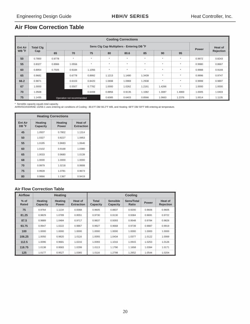
Engineering Design Guide HBH/V SERIES Heat Controller, Inc.
20
Air Flow Correction Table
Airfl ow Heating Cooling% of
RatedHeatingCapacity
Heating Power
Heat of Extraction
Total Capacity
Sensible Capacity
Sens/TotalRatio Power Heat of
Rejection
75 0.9764 1.1134 0.9368 0.9605 0.8837 0.9200 0.9606 0.9605
81.25 0.9829 1.0789 0.9551 0.9730 0.9130 0.9384 0.9691 0.9722
87.5 0.9889 1.0484 0.9717 0.9837 0.9393 0.9548 0.9784 0.9826
93.75 0.9947 1.0222 0.9867 0.9927 0.9668 0.9739 0.9887 0.9919
100 1.0000 1.0000 1.0000 1.0000 1.0000 1.0000 1.0000 1.0000
106.25 1.0050 0.9820 1.0116 1.0055 1.0434 1.0377 1.0122 1.0069
112.5 1.0096 0.9681 1.0216 1.0093 1.1016 1.0915 1.0253 1.0126
118.75 1.0138 0.9583 1.0299 1.0113 1.1790 1.1658 1.0394 1.0171
125 1.0177 0.9527 1.0365 1.0116 1.2798 1.2652 1.0544 1.0204
Cooling Corrections
Ent Air WB ºF
Total Clg Cap
Sens Clg Cap Multipliers - Entering DB ºFPower Heat of
Rejection65 70 75 80 80.6 85 90 95
50 0.7800 0.9778 * * * * * * * 0.9972 0.8243
55 0.8327 0.8966 1.0556 * * * * * * 0.9980 0.8667
60 0.8954 0.7505 0.9184 1.1056 * * * * * 0.9988 0.9169
65 0.9681 0.6778 0.8992 1.1213 1.1480 1.3439 * * 0.9996 0.9747
66.2 0.9871 0.6103 0.8420 1.0698 1.0969 1.2938 * * 0.9999 0.9897
67 1.0000 0.5507 0.7782 1.0000 1.0262 1.2161 1.4266 * 1.0000 1.0000
70 1.0508 0.6408 0.8856 0.9135 1.1082 1.3087 1.4869 1.0005 1.0403
75 1.1435 0.6085 0.6403 0.8566 1.0663 1.2376 1.0014 1.1135
* Sensible capacity equals total capacity.AHRI/ISO/ASHRAE 13256-1 uses entering air conditions of Cooling - 80.6°F DB/ 66.2°F WB, and Heating - 68°F DB/ 59°F WB entering air temperature.
Heating Corrections
Ent Air DB ºF
HeatingCapacity
Heating Power
Heat of Extraction
45 1.0507 0.7802 1.1314
50 1.0327 0.8227 1.0953
55 1.0195 0.8683 1.0646
60 1.0102 0.9168 1.0380
65 1.0033 0.9680 1.0139
68 1.0000 1.0000 1.0000
70 0.9979 1.0218 0.9908
75 0.9928 1.0781 0.9673
80 0.9866 1.1367 0.9419
Air Flow Correction Table
Operation not recommended

Engineering Design Guide HBH/V SERIES Heat Controller, Inc.
21
Antifreeze Correction Table
Antifreeze Type Antifreeze %
Cooling Heating WPDCorr. Fct.EWT 30°F
EWT 90°F EWT 30°FTotal Cap Sens Cap Power Htg Cap Power
Water 0 1.000 1.000 1.000 1.000 1.000 1.000
Propylene Glycol5 0.995 0.995 1.003 0.989 0.997 1.070
15 0.986 0.986 1.009 0.968 0.990 1.210
25 0.978 0.978 1.014 0.947 0.983 1.360
Methanol5 0.997 0.997 1.002 0.989 0.997 1.070
15 0.990 0.990 1.007 0.968 0.990 1.160
25 0.982 0.982 1.012 0.949 0.984 1.220
Ethanol5 0.998 0.998 1.002 0.981 0.994 1.140
15 0.994 0.994 1.005 0.944 0.983 1.300
25 0.986 0.986 1.009 0.917 0.974 1.360
Ethylene Glycol5 0.998 0.998 1.002 0.993 0.998 1.040
15 0.994 0.994 1.004 0.980 0.994 1.120
25 0.988 0.988 1.008 0.966 0.990 1.200

Engineering Design Guide HBH/V SERIES Heat Controller, Inc.
22
Blower Performance Data – Standard Unit
Model FanSpeed
RatedAirfl ow
Min CFM
Airfl ow (cfm) at External Static Pressure (in. wg)0.00 0.05 0.10 0.15 0.20 0.25 0.30 0.35 0.40 0.45 0.50 0.60 0.70 0.80 0.90 1.00
HBH/V 006
HI
220 150
310 300 290 280 270 250 230 210 180
MED 260 250 240 230 210 200 190 150
LOW 210 200 190 180 160 150
HBH/V 009
HI
325 225
410 400 380 360 350 330 320 300 280
MED 390 370 360 340 320 310 290 280 260
LOW 340 330 322 310 300 280 260 250
HBH/V 012
HI
400 300
470 460 450 440 430 420 400 390 380 320
MED 420 410 400 390 380 370 360 350 340
LOW 360 360 350 340 320 320 310 300
HBH/V 015
HI
525 375
745 725 706 696 686 666 637 588 539 451
MED 686 676 666 657 647 637 617 608 588 549 510
LOW 608 598 588 578 568 559 549 529 510 480 451
HBH/V 018
HI
600 450
745 725 706 696 686 666 637 588 539 451
MED 686 676 666 657 647 637 617 608 588 549 510
LOW 608 598 588 578 568 559 549 529 510 480 451
HBH/V 024
HI
800 600
950 922 884 827 732 656
MED 960 950 941 931 912 893 874 855 836 817 789 732 665
LOW 779 770 760 751 741 732 722 713 694 684 665 618
HBH/V 030
HI
1000 750
1102 1074 1045 1017 979 903 798
MED 1188 1169 1140 1121 1093 1064 1036 1017 988 960 922 846
LOW 1064 1045 1017 998 979 960 931 912 884 855 827 751
HBH/V 036
HI
1200 900
1474 1455 1436 1416 1387 1358 1329 1310 1280 1232 1174 1077 931
MED 1174 1164 1106 1106 1096 1096 1086 1077 1067 1038 1009 912
LOW 980 980 970 970 960 960 951 951 941 922 902
HBH/V 041
HI
1325 950
1328 1300 1269 1235 1198 1157 1114 1067 1018 965 910 790 657 512 356 186
MED 1181 1164 1142 1118 1090 1058 1023 985 944 899 850 743 623 489 341 180
LOW 1031 1021 1008 991 971 947 920 890 856 819 778 686 581 461 328 182
HBH/V 042
HI
1350 1050
1558 1530 1501 1473 1444 1416 1378 1340 1302 1264 1226 1131
MED 1416 1397 1368 1349 1321 1302 1273 1245 1207 1169 1131 1064
LOW 1083 1083 1074 1074 1064 1055
HBH/V 048
HI
1600 1200
1881 1853 1815 1767 1710 1653 1596 1416 1216 1216
MED 1843 1824 1805 1786 1767 1729 1682 1653 1625 1577 1520 1340
LOW 1682 1663 1644 1625 1606 1587 1568 1530 1492 1435 1378 1264
HBH/V 060
HI
2000 1500
2195 2195 2185 2176 2156 2117 2078 2048 2019 1999 1970 1921 1842 1754 1627
MED 2009 2009 1999 1980 1950 1931 1901 1882 1852 1823 1793 1744 1676 1588
LOW 1813 1813 1803 1793 1774 1764 1744 1725 1695 1666 1637 1568
Black areas denote ESP where operation is not recommended.Units factory shipped on medium speed. Other speeds require fi eld selection.All airfl ow is rated and shown above at the lower voltage if unit is dual voltage rated, e.g. 208V for 208-230V units.Only two speed fan (H & M) available on 575V units.Performance stated is at the rated power supply, performance may vary as the power supply varies from the rated.
Airfl ow in CFM with wet coil and clean air fi lter

Engineering Design Guide HBH/V SERIES Heat Controller, Inc.
23
Model FanSpeed
RatedAirfl ow
Min CFM
Airfl ow (cfm) at External Static Pressure (in. wg)
0.00 0.05 0.10 0.15 0.20 0.25 0.30 0.35 0.40 0.45 0.50 0.60 0.70 0.80 0.90 1.00
HBH/V 015
HS HI
525 375
774 764 755 745 735 715 696 676 637 519
HS MED 735 725 706 696 686 676 657 657 647 637 617 588 480
HS LOW 657 647 627 617 608 598 588 578 568 568 559 519
HBH/V 018
HS HI
600 450
0 0 0 774 764 755 745 735 715 696 676 637 519
HS MED 735 725 706 696 686 676 657 657 647 637 617 588 480
HS LOW 657 647 627 617 608 598 588 578 568 568 559 519
HBH/V 024
HS HI
800 600
979 903 798 665
HS MED 988 960 922 846 713 589
HS LOW 979 960 931 912 884 855 827 751 675
HBH/V 030
HS HI
1000 750
1102 988 874 760 713
HS MED 1074 1026 979 884 779 713
HS LOW 998 988 979 960 941 931 912 893 865 836 798 713
HBH/V 036
HS HI
1200 900
1484 1455 1426 1358 1251 1135 931
HS MED 1319 1310 1300 1290 1280 1271 1261 1242 1222 1213 1193 1116 1038 883
HS LOW 999 989 980 980 970 970 960 951 931 922 902
HBH/V 042
HS HI
1350 1050
1473 1463 1444 1425 1397 1387 1378 1311 1178 1026
HS MED 1321 1311 1302 1292 1283 1273 1254 1245 1235 1216 1188 1121 1026
HS LOW
HBH/V 048
HS HI
1600 1200
1957 1938 1910 1862 1786 1701 1577 1435
HS MED 1948 1948 1938 1919 1891 1872 1843 1824 1796 1767 1739 1691 1625 1539 1416 1254
HS LOW 1758 1758 1748 1739 1720 1710 1691 1672 1644 1615 1587 1520 1435 1311 1159 0
HBH/V 060
HS HI
2000 1500
2352 2352 2342 2332 2323 2313 2293 2274 2254 2225 2195 2156 2087 2019 1940 1852
HS MED 2117 2117 2107 2107 2097 2068 2038 2019 1999 1989 1980 1940 1891 1842 1460 1715
HS LOW 1891 1891 1882 1882 1872 1862 1852 1852 1842 1833 1813 1793 1764 1715 1666 1588
Black areas denote ESP where operation is not recommended.Units factory shipped on medium speed. Other speeds require fi eld selection.All airfl ow is rated and shown above at the lower voltage if unit is dual voltage rated, e.g. 208V for 208-230V units.Only two speed fan (H & M) available on 575V units.Performance stated is at the rated power supply, performance may vary as the power supply varies from the rated.
Blower Performance Data – High Static

Engineering Design Guide HBH/V SERIES Heat Controller, Inc.
24
Physical Data
HB Series 006 009 012 015 018 024 030 036 041 042 048 060Compressor (1 Each) Rotary Scroll
Factory Charge HFC-410A (oz) 17 18.5 23 32 43 43 47 50 70 70 74 82
PSC Fan Motor & BlowerFan Motor Type/Speeds PSC/3 PSC/3 PSC-3 PSC/3 PSC/3 PSC/3 PSC/3 PSC/3 PSC/3 PSC/3 PSC/3 PSC/3
Fan Motor (hp) 1/25 1/10 1/10 1/6 1/6 1/4 3/4 1/2 3/4 3/4 3/4 1
Blower Wheel Size (Dia x w) 5x5 5x5 6x5 8x7 8x7 9x7 9x7 9x8 9x8 9x8 10x10 11x10
Water Connection SizeFPT 1/2” 1/2” 1/2” 1/2" 1/2" 3/4" 3/4" 3/4" 3/4” 3/4" 1" 1"
Coax Volume (gallons) 0.123 0.143 0.167 0.286 0.450 0.286 0.323 0.323 0.890 0.890 0.738 0.939
VerticalAir Coil Dimensions (H x W) 10x15 10x15 10x15 20x17.25 20x17.25 20x17.25 20x17.25 24x21.75 20x17.25 24x21.76 24x28.25 24x28.25
Filter Standard - 1" Throwaway 10x18 10x18 10x18 20x20 20x20 20x20 20x20 24x24 20x20 24x24 1-14x24, 1-18x24
1-14x24, 1-18x24
Weight - Operating (lbs.) 103 105 114 153 158 189 197 203 210 218 263 278
Weight - Packaged (lbs.) 113 115 124 158 163 194 202 209 217 224 270 285
HorizontalAir Coil Dimensions (H x W) 10x15 10x15 10x15 16x22 16x22 16x22 16x22 20x25 N/A 20x25 20x35 20x35
Filter Standard - 1" Throwaway 10x18 10x18 10x18 16x25 16x25 18x25 18x25 20x28 or 2-20x14 N/A 20x28 or
2-20x141-20x24,1-20x14
1-20x24, 1-20x14
Weight - Operating (lbs.) 103 105 114 153 158 174 182 203 N/A 218 263 278
Weight - Packaged (lbs.) 113 115 124 158 163 179 187 209 N/A 224 270 285
Notes:All units have TXV expansion device, and 1/2” & 3/4” electrical knockouts.FPT = Female Pipe ThreadCondensate Drain Connection is 3/4” FPT.575 volt fan motors are two speed.
Unit Maximum Water Working Pressure Max Pressure PSIG [kPa]
Base Unit 300 [2,068]

Engineering Design Guide HBH/V SERIES Heat Controller, Inc.
25
HB - Horizontal – Dimensional Data
HorizontalModel
Overall CabinetA
WidthB
LengthC
Height
006 - 012 incm
19.148.5
34.186.6
11.128.2
015 - 018 incm
20.151.1
43.1109.5
17.043.2
024 - 030 incm
20.151.1
43.1109.5
18.346.5
036 - 042 incm
20.151.1
47.1119.6
21.053.3
048 - 060 incm
24.161.2
54.1137.4
21.053.3
HorizontalModel
Water Connections1 2 3
Loop In/OutFPTLoop In
DLoop In
ELoop Out
FLoop Out
GCond. 3/4” FPT
AA BB
006 - 012 incm
9.624.3
1.12.7
1.53.8
1.12.7
3.38.4
0.71.8 1/2”
015 incm
15.138.4
1.43.4
3.28.1
1.43.5
3.38.4
0.71.8 1/2”
018 incm
15.138.4
1.43.4
4.110.4
1.43.5
3.38.4
0.71.8 1/2”
024 incm
16.441.7
1.43.4
4.411.3
1.43.5
3.38.4
0.71.8 3/4”
030 incm
16.441.7
1.43.4
3.17.8
1.43.5
3.38.4
0.71.8 3/4”
036 incm
19.148.5
1.43.4
5.313.4
1.43.5
3.38.4
0.71.8 3/4”
042 incm
19.148.5
1.43.4
4.411.3
1.43.5
3.38.4
0.71.8 3/4”
048 incm
19.148.5
1.43.4
4.411.1
1.43.5
3.38.4
0.71.8 1”
060 incm
19.148.5
1.43.4
3.89.7
1.43.5
3.38.4
0.71.8 1”
HorizontalModel
Discharge ConnectionDuct Flange Installed (+/- 0.10 in, +/- 2.5mm)
Return ConnectionUsing Return Air Opening
LM
Supply Height
NSupply Width
O PQ
Return Width
RReturn Height
S T
006 - 012 incm
0.81.9
8.922.7
6.717.0
5.213.3
1.33.3
16.141.0
9.825.0
1.12.7
0.61.5
015 - 018 incm
2.66.6
13.333.8
9.925.1
4.110.5
1.33.3
23.058.4
15.038.1
1.12.8
1.02.5
024 - 030 incm
2.66.6
13.333.8
9.925.1
4.110.5
1.33.3
23.058.4
16.341.4
1.12.8
1.02.5
036 - 042 incm
2.56.3
16.140.9
11.027.9
3.07.7
2.56.4
25.965.8
19.048.3
1.12.8
1.02.5
048 incm
3.79.5
16.141.0
13.734.8
4.110.3
1.33.2
35.991.2
19.048.3
1.12.8
1.02.5
060 incm
1.74.4
18.146.0
13.734.8
4.110.3
1.33.2
35.991.2
19.048.3
1.12.8
1.02.5
HorizontalModel
Electrical KnockoutsH
1/2”J
1/2”K
3/4”Low
VoltageLow
VoltagePowerSupply
006 - 012 incm
8.120.6
5.113.0
2.15.4
015 - 030 incm
12.130.8
9.123.2
6.115.6
036 - 060 incm
16.141.0
13.133.3
10.125.7
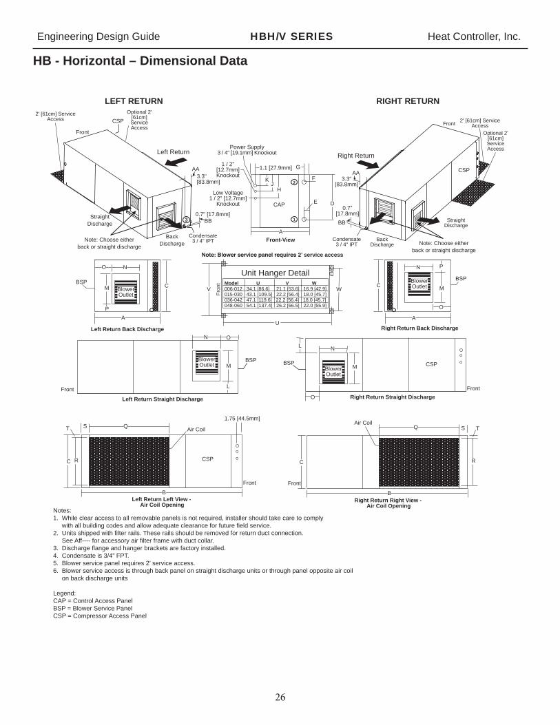
Engineering Design Guide HBH/V SERIES Heat Controller, Inc.
26
HB - Horizontal – Dimensional Data
F
Right Return Straight Discharge
Front
L N
O
M
Right Return
Front
StraightDischarge
CSP
BackDischarge
Condensate3 / 4" IPT
3.3"[83.8mm]
0.7"[17.8mm]
Front-View
E D
KJ 2
1
1.1 [27.9mm]
A
CAP
BSP
Right Return Right View -Air Coil Opening
Air Coil
C
TS
B
R
Q
Front
L
N O
M
Left Return Straight Discharge
Front
BSP
LEFT RETURN RIGHT RETURN
Air Coil
CSP
Front
Left Return Left View -Air Coil Opening
1.75 [44.5mm]
C
T
R
QS
B
Unit Hanger Detail
U
V
Fro
nt
WModel U V W006-012 34.1 [86.6] 21.1 [53.6] 16.9 [42.9]015-030 43.1 [109.5] 22.2 [56.4] 18.0 [45.7]036-042 47.1 [119.6] 22.2 [56.4] 18.0 [45.7]048-060 54.1 [137.4] 26.2 [66.5] 22.0 [55.9]
Right Return Back Discharge
A
Air
Coi
l Sid
e
C
PN
O
M
CSP
BSP
2' [61cm] ServiceAccess
Front
Left Return
0.7" [17.8mm]
3.3"[83.8mm]
CSP
Condensate3 / 4" IPT
2' [61cm] ServiceAccess
Air
Coi
l Sid
e
M
A
C
Left Return Back Discharge
NO
P
BSPBlowerOutlet
BlowerOutlet
BlowerOutlet
BlowerOutlet
Optional 2'[61cm]ServiceAccess
Optional 2'[61cm]ServiceAccess
G
H
service access
Power Supply3 / 4" [19.1mm] Knockout
1 / 2"[12.7mm]Knockout
Low Voltage1 / 2" [12.7mm]
Knockout
3StraightDischarge
BackDischarge
Note: Choose eitherback or straight discharge
Note: Choose eitherback or straight discharge
Notes:1. While clear access to all removable panels is not required, installer should take care to comply with all building codes and allow adequate clearance for future field service. 2. Units shipped with filter rails. These rails should be removed for return duct connection. See Aff---- for accessory air filter frame with duct collar.3. Discharge flange and hanger brackets are factory installed.4. Condensate is 3/4” FPT.5. Blower service panel requires 2’ service access.6. Blower service access is through back panel on straight discharge units or through panel opposite air coil on back discharge units
Legend:CAP = Control Access Panel BSP = Blower Service PanelCSP = Compressor Access Panel
AA
BB
AA
BB
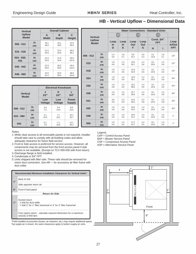
Engineering Design Guide HBH/V SERIES Heat Controller, Inc.
27
HB - Vertical Upfl ow – Dimensional Data
VerticalModel
Electrical KnockoutsJ
1/2”K
1/2”L
3/4”Low
VoltageLow
VoltagePowerSupply
006 - 012 incm
2.97.3
5.914.9
8.922.5
015 - 060 incm
4.110.5
7.118.1
10.125.7
041 incm
3.17.9
7.118.0
11.128.2
Notes:1. While clear access to all removable panels is not required, installer
should take care to comply with all building codes and allow adequate clearance for future fi eld service.
2. Front & Side access is preferred for service access. However, all components may be serviced from the front access panel if side access is not available. (Except on TCV 009-030 with front return)
3. Discharge fl ange is fi eld installed.4. Condensate is 3/4” FPT.5. Units shipped with fi lter rails. These rails should be removed for
return duct connection. See Aff---- for accessory air fi lter frame with duct collar.
VerticalUpfl owModel
Overall CabinetA
WidthB
DepthC
Height
006 - 012 incm
19.148.5
19.148.5
22.055.9
015 - 018 incm
21.554.6
21.554.6
39.099.1
024 - 030, 041
incm
21.554.6
21.554.6
40.0101.6
036 - 042 incm
21.554.6
26.066.0
45.0114.3
048 - 060 incm
24.061.0
32.582.6
46.0116.8
VerticalUpfl owModel
Water Connections - Standard Units1 2 3
LoopInD
LoopInE
LoopOutF
LoopOutG
Cond. 3/4” FPT Loop
In/OutFPTH I
006 - 012 incm
1.43.6
1.64.1
9.524.1
1.64.3
6.115.6
1.64.1 1/2”
015 incm
1.94.8
1.43.6
13.835.1
1.43.6
8.120.6
1.43.6 1/2”
018 incm
1.94.8
1.43.6
12.932.8
1.43.6
8.120.6
1.43.6 1/2”
024 incm
1.94.8
1.43.6
13.835.1
1.43.6
8.120.6
1.43.6 3/4”
030 incm
1.94.8
1.43.6
15.238.6
1.43.6
8.120.6
1.43.6 3/4”
036 incm
1.94.8
1.43.6
15.739.9
1.43.6
8.120.6
1.43.6 3/4”
041 incm
3.64.8
2.35.8
14.035.6
2.35.8
8.120.6
2.35.8 3/4”
042 incm
1.94.8
1.43.6
16.642.0
1.43.6
8.120.6
1.43.6 3/4”
048 incm
1.94.8
1.43.6
16.642.2
1.43.6
8.120.6
1.43.6 1”
060 incm
1.94.8
1.43.6
17.243.7
1.43.6
8.120.6
1.43.6 1”
Legend:CAP = Control Access Panel BSP = Blower Service PanelCSP = Compressor Access Panel ASP = Alternative Service Panel
Recommended Minimum Installation Clearances for Vertical Units*
1”Back of unit
Side opposite return air
6” Front if hard piped
Return Air Side
1”Ducted return- ‡ Add for duct width- † Add 2” for 1” fi lter frame/rail or 3” for 2” fi lter frame/rail
Free (open) return - calculate required dimension for a maximum velocity of 600 fpm
*Field installed accessories (hoses, air cleaners, etc.) may require additional space.Top supply air is shown, the same clearances apply to bottom supply air units.
Air C
oil S
ide
Front
‡ † 1”
1”1”
6”
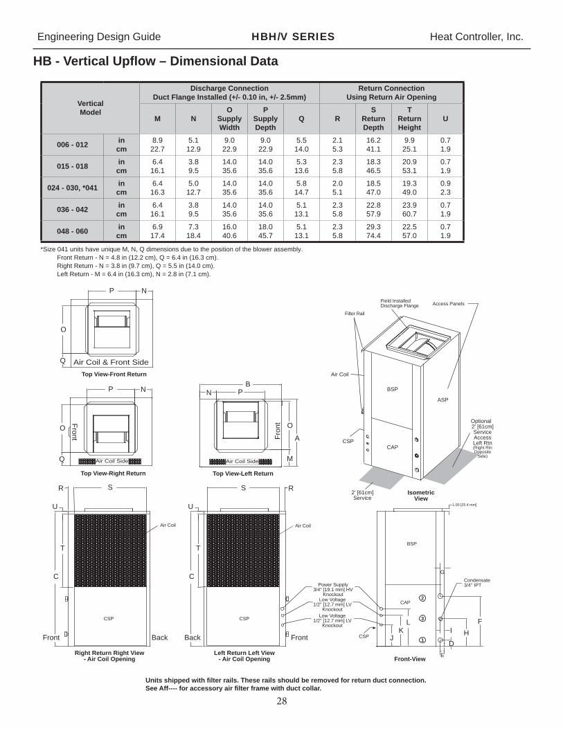
Engineering Design Guide HBH/V SERIES Heat Controller, Inc.
28
HB - Vertical Upfl ow – Dimensional Data
VerticalModel
Discharge ConnectionDuct Flange Installed (+/- 0.10 in, +/- 2.5mm)
Return ConnectionUsing Return Air Opening
M NO
SupplyWidth
PSupplyDepth
Q RS
ReturnDepth
TReturnHeight
U
006 - 012 incm
8.922.7
5.112.9
9.022.9
9.022.9
5.514.0
2.15.3
16.241.1
9.925.1
0.71.9
015 - 018 incm
6.416.1
3.89.5
14.035.6
14.035.6
5.313.6
2.35.8
18.346.5
20.953.1
0.71.9
024 - 030, *041 incm
6.416.3
5.012.7
14.035.6
14.035.6
5.814.7
2.05.1
18.547.0
19.349.0
0.92.3
036 - 042 incm
6.416.1
3.89.5
14.035.6
14.035.6
5.113.1
2.35.8
22.857.9
23.960.7
0.71.9
048 - 060 incm
6.917.4
7.318.4
16.040.6
18.045.7
5.113.1
2.35.8
29.374.4
22.557.0
0.71.9
Access Panels
Top View-Left Return
U
RSIsometric
View
Left Return Left View- Air Coil Opening
T
CPower Supply
3/4" [19.1 mm] HVKnockout
Low Voltage1/2" [12.7 mm] LV
KnockoutLow Voltage
1/2" [12.7 mm] LVKnockout
Condensate3/4" IPT
Front-View
K
1.00 [25.4 mm]
F
JH
D
L
Air Coil
Field InstalledDischarge Flange
FrontBack
U
R S
T
C
BackFront
Right Return Right View- Air Coil Opening
BSP
CAP
Filter Rail
ASP
Air Coil
Fro
nt
Optional2' [61cm]ServiceAccessLeft Rtn(Right RtnOpposite
Side)
NB
P
A
O
M
2' [61cm]Service
3
2
1
E
I
G
Top View-Right Return
Top View-Front Return
P N
O
Q
CSP
CAP
CSPCSP
CSP
Air Coil
Air Coil Side
BSP
Air Coil & Front Side
Units shipped with filter rails. These rails should be removed for return duct connection. See Aff---- for accessory air filter frame with duct collar.
Front
P N
O
Q Air Coil Side
*Size 041 units have unique M, N, Q dimensions due to the position of the blower assembly. Front Return - N = 4.8 in (12.2 cm), Q = 6.4 in (16.3 cm). Right Return - N = 3.8 in (9.7 cm), Q = 5.5 in (14.0 cm). Left Return - M = 6.4 in (16.3 cm), N = 2.8 in (7.1 cm).

Engineering Design Guide HBH/V SERIES Heat Controller, Inc.
29
Corner Weights for HB Series Units
Model Total Left-Front* Right-Front* Left-Back* Right-Back*
HBH006Lbs 103 37 24 23 19
kg 46.72 16.78 10.89 10.43 8.62
HBH009Lbs 105 38 24 23 20
kg 47.63 17.24 10.89 10.43 9.07
HBH012Lbs 114 42 26 25 21
kg 51.71 19.05 11.79 11.34 9.53
HBH015Lbs 153 53 36 34 30
kg 69 24 16 15 14
HBH018Lbs 158 55 37 35 31
kg 72 25 17 16 14
HBH024Lbs 174 62 40 39 33
kg 79 28 18 18 15
HBH030Lbs 182 67 41 40 34
kg 83 30 19 18 15
HBH036Lbs 203 75 47 44 37
kg 92 34 21 20 17
HBH042Lbs 218 81 50 48 39
kg 99 37 23 22 18
HBH048Lbs. 263 98 60 58 47
kg 119 44 27 26 21
HBH060Lbs. 278 94 59 56 69
kg 126 43 27 25 31
*Front is control box end.

Engineering Design Guide HBH/V SERIES Heat Controller, Inc.
30
Electrical Data – Standard Unit
Model VoltageCode
RatedVoltage
VoltageMin/Max
Compressor FanMotorFLA
TotalUnitFLA
MinCircuitAmp
MaxFuse/HACRQTY RLA LRA
006G 208-230/60/1 197/254 1 3.3 17.7 0.40 3.7 4.5 15
E 265/60/1 239/292 1 2.9 13.5 0.40 3.3 4.0 15
009G 208-230/60/1 197/254 1 4.5 22.2 0.92 5.4 6.5 15
E 265/60/1 239/292 1 3.8 18.8 0.70 4.5 5.5 15
012G 208-230/60/1 197/254 1 5.1 32.5 0.92 6.0 7.3 15
E 265/60/1 239/292 1 4.0 31.5 0.70 4.7 5.7 15
015G 208-230/60/1 197/254 1 6.0 29.0 1.20 7.2 8.7 15
E 265/60/1 239/292 1 5.4 28.0 0.86 6.8 8.2 15
018G 208-230/60/1 197/254 1 7.2 33.0 1.20 8.4 10.2 15
E 265/60/1 239/292 1 5.9 28.0 0.86 6.8 8.2 15
024
G 208-230/60/1 197/254 1 12.8 58.3 1.50 14.3 17.5 30
E 265/60/1 239/292 1 9.6 54.0 1.30 10.9 13.3 20
H 208-230/60/3 197/254 1 7.7 55.4 1.50 9.2 11.1 15
F 460/60/3 414/506 1 3.6 28.0 0.76 4.4 5.3 15
030
G 208-230/60/1 197/254 1 14.1 73.0 3.00 17.1 20.6 30
E 265/60/1 239/292 1 11.2 60.0 2.70 13.9 16.7 25
H 208-230/60/3 197/254 1 8.9 58.0 3.00 11.9 14.1 20
F 460/60/3 414/506 1 4.2 28.0 1.70 5.9 7.0 15
036
G 208-230/60/1 197/254 1 16.7 79.0 1.80 18.5 22.7 35
E 265/60/1 239/292 1 13.5 72.0 2.00 15.5 18.9 30
H 208-230/60/3 197/254 1 10.4 73.0 1.80 12.2 14.8 25
F 460/60/3 414/506 1 5.8 38.0 1.24 7.0 8.5 15
041
G 208-230/60/1 197/254 1 17.9 112.0 3.00 20.9 25.4 40
H 208-230/60/3 197/254 1 13.2 88.0 3.00 16.2 19.5 30
F 460/60/3 414/506 1 6.0 44.0 1.70 7.7 9.2 15
N 575/60/3 518/633 1 4.2 30.0 1.40 5.6 6.7 15
042
G 208-230/60/1 197/254 1 17.9 112.0 3.00 20.9 25.4 40
H 208-230/60/3 197/254 1 13.5 88.0 3.00 16.5 19.9 30
F 460/60/3 414/506 1 6.0 44.0 1.70 7.7 9.2 15
N 575/60/3 518/633 1 4.9 34.0 1.40 6.3 7.5 15
048
G 208-230/60/1 197/254 1 21.8 117.0 3.40 25.2 30.7 50
H 208-230/60/3 197/254 1 13.7 83.1 3.40 17.1 20.5 30
F 460/60/3 414/506 1 6.2 41.0 1.80 8.0 9.6 15
N 575/60/3 518/633 1 4.8 33.0 1.40 6.2 7.4 15
060
G 208-230/60/1 197/254 1 26.3 134.0 4.90 31.2 37.8 60
H 208-230/60/3 197/254 1 15.6 110.0 4.90 20.5 24.4 40
F 460/60/3 414/506 1 7.8 52.0 2.50 10.3 12.3 20
N 575/60/3 518/633 1 5.8 38.9 1.90 7.7 9.2 15
HACR circuit breaker in USA onlyAll fuses Class RK-5

Engineering Design Guide HBH/V SERIES Heat Controller, Inc.
31
Electrical Data – High Static Blower
HBModel
VoltageCode
RatedVoltage
VoltageMin/Max
Compressor FanMotorFLA
TotalUnitFLA
MinCircuitAmp
MaxFuse/HACRQTY RLA LRA
015G 208-230/60/1 197/254 1 6.0 29.0 1.20 7.2 8.7 15
E 265/60/1 239/292 1 5.4 28.0 0.86 6.3 7.6 15
018G 208-230/60/1 197/254 1 7.2 33.0 1.50 8.7 10.5 15
E 265/60/1 239/292 1 5.9 28.0 1.30 7.2 8.7 15
024
G 208-230/60/1 197/254 1 12.8 58.3 1.50 14.3 17.5 30
E 265/60/1 239/292 1 9.6 54.0 1.30 10.9 13.3 20
H 208-230/60/3 197/254 1 7.7 55.4 1.50 9.2 11.1 15
F 460/60/3 414/506 1 3.6 28.0 0.76 4.4 5.3 15
030
G 208-230/60/1 197/254 1 14.1 73.0 3.00 17.1 20.6 30
E 265/60/1 239/292 1 11.2 60.0 2.70 13.9 16.7 25
H 208-230/60/3 197/254 1 8.9 58.0 3.00 11.9 14.1 20
F 460/60/3 414/506 1 4.2 28.0 1.70 5.9 7.0 15
036
G 208-230/60/1 197/254 1 16.7 79.0 3.00 19.7 23.9 40
E 265/60/1 239/292 1 13.5 72.0 2.70 16.2 19.6 30
H 208-230/60/3 197/254 1 10.4 73.0 3.00 13.4 16.0 25
F 460/60/3 414/506 1 5.8 38.0 1.70 7.5 9.0 15
042
G 208-230/60/1 197/254 1 17.9 112.0 3.00 20.9 25.4 40
H 208-230/60/3 197/254 1 13.5 88.0 3.00 16.5 19.9 30
F 460/60/3 414/506 1 6.0 44.0 1.70 7.7 9.2 15
N 575/60/3 518/633 1 4.9 34.0 1.40 6.3 7.5 15
048
G 208-230/60/1 197/254 1 21.8 117.0 4.90 26.7 32.2 50
H 208-230/60/3 197/254 1 13.7 83.1 4.90 18.6 22.0 35
F 460/60/3 414/506 1 6.2 41.0 2.50 8.7 10.3 15
N 575/60/3 518/633 1 4.8 33.0 1.90 6.7 7.9 15
060
G 208-230/60/1 197/254 1 26.3 134.0 5.80 32.1 38.7 60
H 208-230/60/3 197/254 1 15.6 110.0 5.80 21.4 25.3 40
F 460/60/3 414/506 1 7.8 52.0 2.60 10.4 12.4 20
N 575/60/3 518/633 1 5.8 38.9 2.30 8.1 9.6 15
HACR circuit breaker in USA onlyAll fuses Class RK-5

Engineering Design Guide HBH/V SERIES Heat Controller, Inc.
32
HB Series Wiring Diagram Matrix
Model Wiring DiagramPart Number Electrical Control DDC Agency
HB Series Single Phase
96B0006N01
208-230/60/1, 265/60/1
CXM
- ETL
96B0006N03 LON ETL
96B0006N09 MPC ETL
96B0006N02
DXM
- ETL
96B0006N04 LON ETL
96B0006N10 MPC ETL
HB Series Three Phase (230V Style)
96B0007N01
208-230/60/3
CXM
- ETL
96B0007N03 LON ETL
96B0007N06 MPC ETL
96B0007N02
DXM
- ETL
96B0007N04 LON ETL
96B0007N07 MPC ETL
HB Series Three Phase (460V Style)
96B0008N01
460/60/3, 575/60/3
CXM
- ETL
96B0008N03 LON ETL
96B0008N08 MPC ETL
96B0008N02
DXM
- ETL
96B0008N04 LON ETL
96B0008N09 MPC ETL
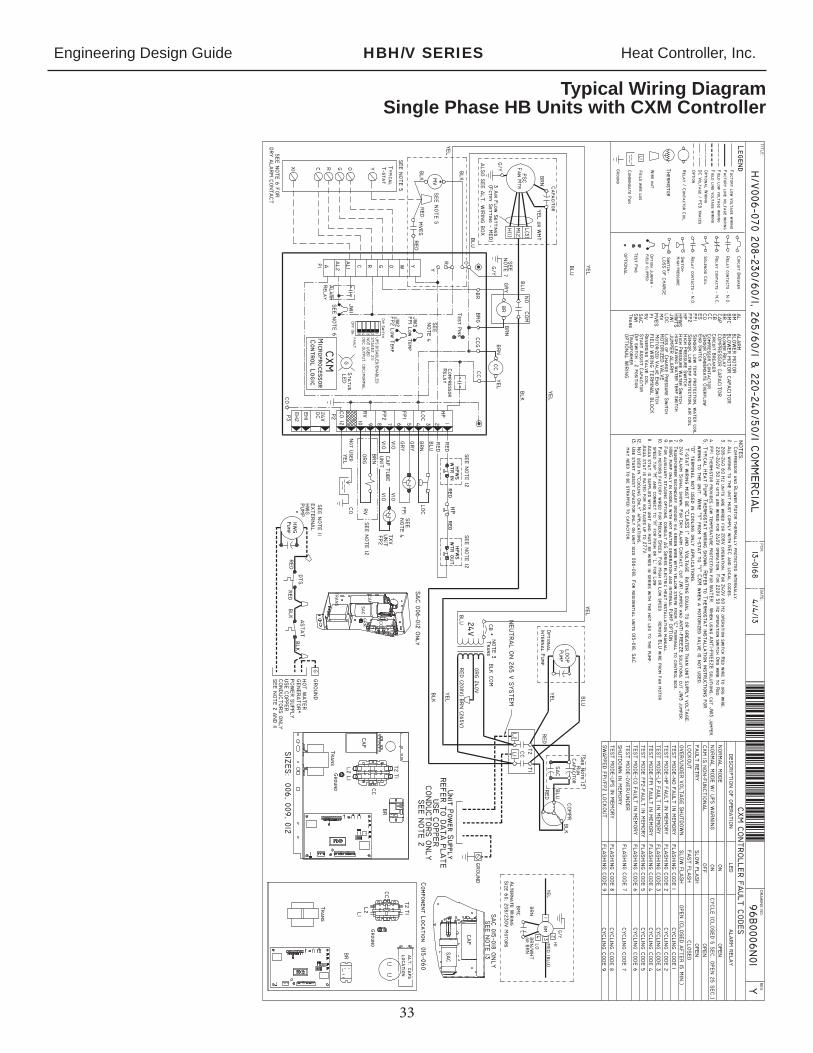
Engineering Design Guide HBH/V SERIES Heat Controller, Inc.
33
Typical Wiring DiagramSingle Phase HB Units with CXM Controller

Engineering Design Guide HBH/V SERIES Heat Controller, Inc.
34
Typical Wiring DiagramThree Phase 208/230V HB Units with CXM Controller
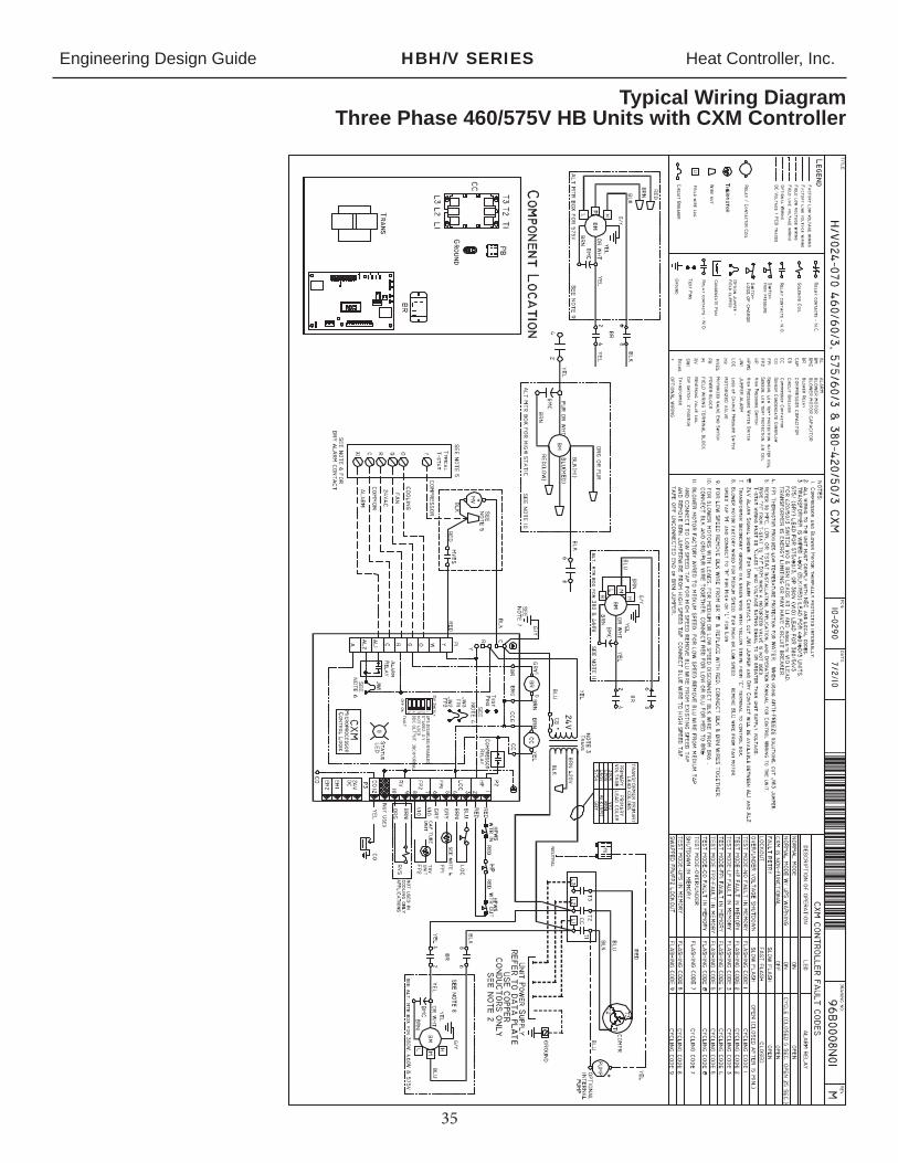
Engineering Design Guide HBH/V SERIES Heat Controller, Inc.
35
Typical Wiring DiagramThree Phase 460/575V HB Units with CXM Controller

04/2014
skanalas
Typewritten Text
skanalas
Typewritten Text
skanalas
Typewritten Text
skanalas
Typewritten Text
skanalas
Typewritten Text
skanalas
Typewritten Text
skanalas
Typewritten Text
skanalas
Typewritten Text
skanalas
Typewritten Text
skanalas
Typewritten Text
skanalas
Sticky Note
UPDATED: 11/2014