Commercial Grade Conductive Heat Shrinkable EMI Cable
12
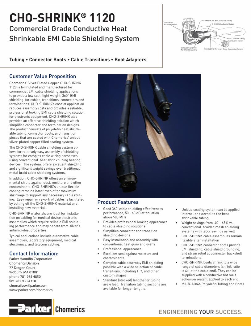
Customer Value Proposition Chomerics’ Silver Plated Copper CHO-SHRINK 1120 is formulated and manufactured for commercial EMI cable shielding applications to provide a low cost, light weight, 360° EMI shielding for cables, transitions, connectors and terminations. CHO-SHRINK’s ease of application reduces assembly costs and provides a reliable, professional looking EMI cable shielding solution for electronic equipment. CHO-SHRINK also provides an effective shielding solution which simplifies connector and termination designs. The product consists of polyolefin heat shrink- able tubing, connector boots, and transition pieces that are coated with Chomerics’ unique silver-plated copper filled coating system. The CHO-SHRINK cable shielding system al- lows for relatively easy assembly of shielding systems for complex cable wiring harnesses using conventional heat shrink tubing heating devices. The system offers excellent shielding and significant weight savings over traditional metal braid cable shielding systems. In addition, CHO-SHRINK offers an environ- mental shield against dust, moisture and other contaminants. CHO-SHRINK's unique flexible coating remains intact even after maximum shrinkage to support any necessary cable rout- ing. Easy repair or rework of cables is facilitated by cutting off the CHO-SHRINK material and installing new material. CHO-SHRINK materials are ideal for installa- tion on cabling for medical device electronic assemblies which require reliable EMI shield- ing performance and may benefit from silver’s antimicrobial properties. Typical applications include automotive cable assemblies, laboratory equipment, medical electronics, and telecom cabling. CHO-SHRINK ® 1120 Commercial Grade Conductive Heat Shrinkable EMI Cable Shielding System Contact Information: Product Features • Good 360° cable shielding effectiveness performance, 50 - 60 dB attenuation above 500 MHz • Provides professional looking appearance to cable shielding solutions • Simplifies connector and transition shielding designs • Easy installation and assembly with conventional heat guns and ovens • Professional appearance • Excellent seal against moisture and contaminants • Complex cable assembly EMI shielding possible with a wide selection of cable transitions, including T, Y, and other custom shapes • Standard (stocked) lengths for tubing are 4 feet. Transition tubing sections are available for longer lengths. • Unique coating system can be applied internal or external to the heat shrinkable tubing • Weight savings from 40 – 65% vs. conventional braided mesh shielding systems with labor savings as well • CHO-SHRINK cable assemblies remain flexible after installation • CHO-SHRINK connector boots provide EMI shielding, cable shield grounding, and strain relief at connector backshell terminations. • CHO-SHRINK boots shrink to a wide range of cable diameters (shrink ratio is 4:1 at the cable end). They can be supplied with a conductive hot melt adhesive/sealant applied to each end. • Mil-R-46846 Polyolefin Tubing and Boots Tubing • Connector Boots • Cable Transitions • Boot Adapters CHO-BOND Adhesive/Sealant CHO-SHRINK 90° Boot (Conductive Side) CHO-SHRINK Tubing (Conductive Inside) CHO-SHRINK Continuity Splice (Conductive Outside) Conductive Grommet For Shield Grounding CHO-BOND Adhesive/Sealant Parker Hannifin Corporation Chomerics Division 77 Dragon Court Woburn, MA 01801 phone 781 935 4850 fax 781 933 4318 [email protected] www.parker.com/chomerics
Transcript of Commercial Grade Conductive Heat Shrinkable EMI Cable
Customer Value PropositionChomerics’ Silver Plated Copper CHO-SHRINK 1120 is formulated and manufactured for commercial EMI cable shielding applications to provide a low cost, light weight, 360° EMI shielding for cables, transitions, connectors and terminations. CHO-SHRINK’s ease of application reduces assembly costs and provides a reliable, professional looking EMI cable shielding solution for electronic equipment. CHO-SHRINK also provides an effective shielding solution which simplifies connector and termination designs. The product consists of polyolefin heat shrink-able tubing, connector boots, and transition pieces that are coated with Chomerics’ unique silver-plated copper filled coating system.
The CHO-SHRINK cable shielding system al-lows for relatively easy assembly of shielding systems for complex cable wiring harnesses using conventional heat shrink tubing heating devices. The system offers excellent shielding and significant weight savings over traditional metal braid cable shielding systems.
In addition, CHO-SHRINK offers an environ-mental shield against dust, moisture and other contaminants. CHO-SHRINK's unique flexible coating remains intact even after maximum shrinkage to support any necessary cable rout-ing. Easy repair or rework of cables is facilitated by cutting off the CHO-SHRINK material and installing new material.
CHO-SHRINK materials are ideal for installa-tion on cabling for medical device electronic assemblies which require reliable EMI shield-ing performance and may benefit from silver’s antimicrobial properties.
Typical applications include automotive cable assemblies, laboratory equipment, medical electronics, and telecom cabling.
CHO-SHRINK® 1120Commercial Grade Conductive Heat Shrinkable EMI Cable Shielding System
Contact Information:
Product Features• Good 360° cable shielding effectiveness
performance, 50 - 60 dB attenuation above 500 MHz
• Provides professional looking appearance to cable shielding solutions
• Simplifies connector and transition shielding designs
• Easy installation and assembly with conventional heat guns and ovens
• Professional appearance• Excellent seal against moisture and
contaminants• Complex cable assembly EMI shielding
possible with a wide selection of cable transitions, including T, Y, and other custom shapes
• Standard (stocked) lengths for tubing are 4 feet. Transition tubing sections are available for longer lengths.
• Unique coating system can be applied internal or external to the heat shrinkable tubing
• Weight savings from 40 – 65% vs. conventional braided mesh shielding systems with labor savings as well
• CHO-SHRINK cable assemblies remain flexible after installation
• CHO-SHRINK connector boots provide EMI shielding, cable shield grounding, and strain relief at connector backshell terminations.
• CHO-SHRINK boots shrink to a wide range of cable diameters (shrink ratio is 4:1 at the cable end). They can be supplied with a conductive hot melt adhesive/sealant applied to each end.
• Mil-R-46846 Polyolefin Tubing and Boots
Tubing • Connector Boots • Cable Transitions • Boot Adapters
CHO-BOND Adhesive/Sealant
CHO-SHRINK 90° Boot (Conductive Side)
CHO-SHRINK Tubing(Conductive Inside)
CHO-SHRINK Continuity Splice (Conductive Outside)Conductive GrommetFor Shield Grounding
CHO-BONDAdhesive/Sealant
Parker Hannifin CorporationChomerics Division77 Dragon CourtWoburn, MA 01801phone 781 935 4850fax 781 933 [email protected]/chomerics

Application Instructions• One of the major advantages of the
CHO-SHRINK EMI cable shielding system over conventional metal shielding is its ease of assembly. The following has been prepared as a guide to the proper application and assembly of CHO-SHRINK tubing, connector boots, and transitions.
• All CHO-SHRINK products may be recovered (shrunk) with the same heating equipment used on ordinary nonconductive shrinkable plastics. Hot air blowers and infrared heating devices provide the simplest method of shrinking. Ovens may be used to recover tubing, but boots, transitions and other molded parts often require some hand positioning during the shrinking process to assure correct alignment. Shrink temperatures should not exceed 375°F. Care should be taken to shrink the product slowly and uniformly. Exceeding 375°F (191°C) may cause a loss of shielding integrity.
• To achieve a good mechanical grip between CHO-SHRINK boots and connector backshells, Chomerics strongly recommends the use of Shrink Boot Adapters, which provide a knurled and grooved surface to enhance resistance to torque, snap-off and pull-off stresses. Tie-wraps should also be applied.
• CHO-SHRINK molded parts are available with a highly conductive hot-melt adhesive/sealant at each opening. This hot melt will flow during shrinking to provide an effective environmental seal without degrading EMI shielding characteristics. If excess sealant flows outside the molded part during recovery, it can be easily wiped away while still warm.
• The only assembly procedure peculiar to CHO-SHRINK is the necessity to maintain electrical continuity through conductive inside surfaces from connector to connector. Where two CHO-SHRINK parts meet (boot/tubing, tubing/transition, etc.), a continuity splice must be achieved. This is accomplished by using CHO-SHRINK splice sleeves, which are short lengths of CHO-SHRINK tubing with a conductive outside surface.
• For optimal shielding performance, be sure to terminate the shield at both ends with full 360° contact to a low impedance ground. Incorporate mechanical strain relief into the cable design itself. That is, avoid stretching and bending the cable excessively. Transition pieces should be generous to preserve continuity at all junction points.
2

CHO-SHRINK Assembly Procedure
1. Lay out entire cable, with all branches in proper place.
2. Slide CHO-SHRINK continuity splice sleeves (coating outside, black inside) into position wherever connector boots or transitions will be shrunk against the cable.
3. Apply heat to shrink continuity splices tightly against wire bundle.
4. Slide pre-cut lengths of CHO-SHRINK tubing (inside-coated) into position so that ends overlap approximately one-half of each continuity splice sleeve. When determining cut-lengths, allow for a maximum of 5% longitudinal shrinkage.
5. Apply heat to shrink tubing against wire bundle. Approximately ½ to 1 -1/2 inches of conductive surface should be exposed at each continuity splice.
6. Slide CHO-SHRINK transitions into position, bending branches where required to allow the expanded transition to pass breakout intersections. When properly positioned, exposed continuity splices should be entirely covered by the transition.
7. Apply heat to shrink transitions in place. During the shrinking process, transitions can be positioned by hand to assure correct alignment and convenient breakout angles. Ends of each transition should be pressed down onto the splice sleeve so that the conductive hot melt adhesive around each opening flows around splice to provide a mechanical bond and seal. Note: Do not handle cables after transition shrinkage until cool.
8. If CHO-SEAL conductive grommets are to be used to terminate individual wire shields: a. Strip outer jacket off each wire and cut shield away leaving ¼” – 3/8” of shield exposed. b. Comb exposed shield back over jacket. c. Insert wires into grommet so that exposed shields are securely located in center of grommet.
9. Terminate connector. Note: If connector backshell does not provide a knurled and grooved surface for the CHO-SHRINK boot to grasp, a Shrink Boot Adapter should be installed on the backshell before wires are terminated (see table of Adapter sizes and part numbers).
10. Slide CHO-SHRINK boot over connector, and align so that boot will shrink over threads of backshell (or adapter) at one end and exposed continuity splice at other end.
11. Apply heat and begin shrinking boot at connector end first, using hands to assure proper positioning. Press boot tightly against backshell so that conductive hot melt adhesive provides mechanical bond and seal. Continue shrinking boot, working from connector towards cable. Press “tail” end of boot down against exposed splice so that conductive hot melt bonds and seals.
3

Product Information
Typical Properties CHO-SHRINK® 1120: CHO-SHRINK Boots
CHO-SHRINK® 1120: CHO-SHRINK Tubing
Boot Material Heat shrinkable polyolefin per MIL-R-46846 Type 5
Conductive Filler Silver-plated copper in polyolefin
Shore D Hardness (ASTM D-676) 50 ±10
Operating Temperature Limits -55°C to 150°C (-67°F to 300°F) -54°C to 135°C (-66°F to 275°F)
Dielectric Strength* (ASTM D-876) 200 V/mil
Shrink Temperature 121°C (250°F) min. 191°C (375°F) max.
Outgassing (NASA Reference Publication 1124) (ASTM E595)
Total Mass Loss (TML) (%) 0.68 0.68
Collectible Volatile Condensable Materials (CVCM) (%) 0.05 0.05
Flammability (ASTM D-635)*** UL VW-1 UL VW-1
Shrink Ratio up to 4:1 up to 2:1
Shielding Effectiveness (CHO-TM-TP12) See Figure 1 See Figure 1
DC Resistance** N/A 1.0 ohm/foot
Shelf Life (from date of manufacture) 2 years 2 years
* Recovered base material ** After 100% recovery*** Tested internally by Chomerics
Figure 1 Shielding Effectiveness for CHO-SHRINK 1120, 1/2” diameter tubing
4
CHO-SHIELD® 1120 Typical Shielding Effectiveness Per CHO-TM-TP12
Att
enua
tion
(dB
)
Frequency (MHz)10,00010 1,000 100
10
0
20
30
40
60
70
80
50

Ordering InformationCHO-SHRINK® Tubing
Use the following part numbering system to order CHO-SHRINK tubing. Standard (stocked) lengths are 4 feet. Ordering quantity should specify total length required. Part number indicates length of pieces.
Example: 70-41-0016-0004-10 = 4 feet of 1” diameter, with tubing coated on the inside cut to 10" lengths
70 - 4 - - 0004 -
Coating Configuration1 = Coated inside2 = Coated outside3 - Coated inside & outside
Expanded Inside Diameter CodeEnter inside diameter in 1/16ths For example: 0004 = 1/4” ID0008 = 1/2” ID0016 = 1” ID
Cut lengths are in inchesFor example: 10 = 10 inches
Available Standard Diameters and Wall ThicknessesExpandedInside Dia.
Inches (mm)
ExpandedInside Dia.
Code
Typical Recovered Wall Thickness
Inches (mm)1/8 (3.18) 0002 .020 (0.51)
3/16 (4.76) 0003 .020 (0.51)
¼ (6.35) 0004 .025 (0.63)3/8 (9.53) 0006 .025 (0.63)
½ (12.7) 0008 .025 (0.63)
¾ (19.05) 0012 .030 (0.76)
1 (25.4) 0016 .035 (0.89)
For non-standard sizes, contact Chomerics.
5

CHO-SHRINK Straight Polyolefin Boots with Lip. (To Fit Shrink Boot Adapters) A
E
FH
G
B Dia.
D Dia.
C Dia.
Chomerics Part Number*
Nominal Dimensions, inches (mm in parentheses)
For Use With…A B Dia. C Dia. D E F G H
Recovered (±20%
)
Supplied (m
in)
Recovered (m
ax)
Supplied (m
in)
Recovered (m
ax)
Recovered (±20%
)
Recovered (±20%
)
Recovered (±20%
)
Recovered
Recovered
Mil-C-5015
AdaptersMIL-C-26482
Adapters
Solid Rotating
71-04-7053-XXXX
1.50(38.10)
.92(23.37)
.41(10.41)
.92(23.37)
.22(5.59)
.07(1.78)
.92(23.37
.40(10.16)
.04(1.02)
.12(3.05)
— — 8
71-04-7054-XXXX
2.16(54.86)
1.12(28.45)
0.56(14.22)
1.12(28.45)
0.26(6.60)
0.07(1.78)
1.27(32.26)
.65(16.51)
.04(1.02)
.12(3.05)
10SL, 12S
8 10
71-04-7055-XXXX
2.63(66.80)
1.22(30.99)
.70(17.78)
1.22(30.99)
.28(7.11)
.08(2.03)
1.59(40.39)
.70(17.78)
.04(1.02)
.12(3.05)
14S 10 12, 14
71-04-7056-XXXX
3.15(80.01)
1.42(36.07)
.88(22.35)
1.42(36.07)
.33(8.38)
.08(2.03)
1.73(43.94)
.82(20.83)
.04(1.02)
.12(3.05)
16S, 16, 18
12, 14 16, 18
71-04-7057-XXXX
4.08(103.63)
1.68(42.67)
1.11(28.19)
1.68(42.67)
.39(9.91)
.09(2.29)
2.47(62.74)
.97(24.64)
.065(1.65)
.12(3.05)
20, 22 16, 18 20
71-04-7058-XXXX
5.13(130.30)
2.04(51.82)
1.38(35.05)
2.04(51.82)
.62(15.75)
.13(3.30)
3.02(76.71)
1.56(39.62)
.065(1.65)
.12(3.05)
24, 28 20, 22, 24
22, 24
71-04-7059-XXXX
6.50(165.10)
2.60(66.04)
1.75(44.45)
2.60(66.04)
.80(20.32)
.16(4.06)
3.55(90.17)
1.90(48.26)
.08(2.03)
.12(3.05)
32, 36 — —
CHO-SHRINK 90° Polyolefin Boots with Lip (To Fit Shrink Boot Adapters)
E
C
F
I H
G
A Dia.
D Typ.
B Dia.
Chomerics Part
Number*
Nominal Dimensions, inches (mm in parentheses)
For Use With…A Dia. B Dia. C D E F G H ISupplied
(min)
Recovered (m
ax)
Supplied (m
in)
Recovered (m
ax)
Recovered (±10%
)
Recovered (±20%
)
Recovered (±10%
)
Recovered (±10%
)
Recovered (±10%
)
Recovered (±20%
)
Recovered (±10%
)
Mil-C-5015
Adapters
MIL-C-26482 Adapters
Solid Rotating
71-04-7126-XXXX
.92(23.37)
.41(10.41)
.92(23.37)
.22(5.59)
.84(21.34)
.05(1.27)
.23(5.84)
.65(16.51)
.89(22.61)
.04(1.02)
.12(3.05)
— — 8
71-04-7127-XXXX
1.12(28.45)
.56(14.22)
1.12(28.45)
.26(6.60)
1.33(33.78)
.06(1.52)
.65(16.51)
.76(19.30)
1.07(27.18)
.04(1.02)
.12(3.05)
10SL, 12S
8 10
71-04-7128-XXXX
1.22(30.99)
.70(17.78)
1.22(30.99)
.28(7.11)
1.44(36.58)
.07(1.78)
.50(12.70)
.83(21.08)
1.22(30.99)
.04(1.02)
.12(3.05)
14S 10 12, 14
71-04-7129-XXXX
1.42(36.07)
.88(22.35)
1.42(36.07)
.33(8.38)
1.72(43.69)
.07(1.78)
.57(14.48)
.90(22.86)
1.38(35.05)
.04(1.02)
.12(3.05)
16S, 16, 18
12, 14 16, 18
71-04-7130-XXXX
1.68(42.67)
1.11(28.19)
1.68(42.67)
.39(9.91)
2.11(53.59)
.08(2.03)
.69(17.53)
1.14(28.96)
1.73(43.94)
.065(1.65)
.12(3.05)
20, 22 16, 18 20
71-04-7131-XXXX
2.04(51.82)
1.38(35.05)
2.04(51.82)
.62(15.75)
3.07(77.98
.13(3.30)
1.32(33.53)
1.32(33.53)
2.08(52.83)
.065(1.65)
.12(3.05)
24, 28 20, 22, 24
22, 24
71-04-7132-XXXX
2.60(66.04)
1.75(44.45)
2.60(66.04)
.80(20.32)
3.84(97.54)
.15(3.81)
1.58(40.13)
1.65(41.66)
2.60(66.04)
.08(2.03)
.12(3.05)
32, 36 — —
NOTE: For non-lipped boots and alternate configurations, contact Chomerics. *XXXX will indicate adhesive/sealant option: if desired, last four digits shall be 1000; if not desired specify 0000. Allow 0.020” (0.51 mm) nominal adhesive thickness on the “Supplied” and “Recovered” diameters.
6

CHO-SHRINK Side Entry 90° Rectangular Polyolefin Boot
A
H
X
X
DSection X - X
G
B
GE
.310
C Dia.
Chomerics Part Number*
Nominal Dimensions, inches (mm in parentheses)
“D” Subminia-ture Connector
Pin Count
A B C Dia. D E F G H
Recovered (±10%
)
Recovered (±20%
)
Supplied (m
in)
Recovered (m
ax)
Recovered (±20%
)
Recovered (±10%
)
Recovered (±10%
)
Supplied (±5%
)
Recovered (±5%
)
Supplied (±5%
)
Recovered (±5%
)
71-04-7604-XXXX 1.10(27.94)
.12(3.05)
.31(7.87)
.16(4.06)
.04(1.02)
.50(12.70)
.73(18.54)
.80(20.352)
.80(20.32)
.42(10.67)
.42(10.67)
9
71-04-7605-XXXX 1.38(35.05)
.12(3.05)
.40(10.16)
.21(5.33)
.04(1.02)
.50(12.70)
.74(18.80)
1.11(28.19)
1.11(28.19)
.42(10.67)
.42(10.67)
15
71-04-7606-XXXX 1.87(47.50)
.12(3.05)
.55(13.97)
.25(6.35)
.04(1.02)
56(14.22)
.79(20.07)
1.66(42.16)
1.66(42.16)
.42(10.67)
.42(10.67)
25
71-04-7607-XXXX 2.35(59.69)
.12(3.05)
.68(17.27)
.31(7.87)
.04(1.02)
56(14.22)
.79(20.07)
2.31(58.67)
2.31(58.67)
.42(10.67)
.42(10.67)
37
71-04-7608-XXXX 2.49(63.25)
.12(3.05)
.75(19.05)
.36(9.14)
.04(1.02)
.69(17.53)
1.04(26.42)
2.28(57.91)
2.28(57.91)
.54(13.72)
.54(13.72)
50
CHO-SHRINK Top Entry Rectangular Polyolefin Boot
FH
K
JM
E
D
B
Tan.
Tan.C
A Dia. G Typ.
.08 Dia. Holes(2 Places)
I Typ.
L Typ.
Chomerics Part
Number*
Nominal Dimensions, inches (mm in parentheses)
A Dia. B C D E F G H I J K L M
Fits Cinch Tykon
Connectors
Supplied (m
in)
Recovered (m
ax)
Recovered (±10%
)
Recovered (±10%
)
Recovered (±10%
)
Recovered (±10%
)
Supplied (m
in)
Recovered (m
ax)
Recovered (±20%
)
Recovered (±10%
)
Recovered (±20%
)
Recovered (±10%
)
Recovered (±10%
)
Recovered (±20%
)
Supplied (m
in)
Recovered (m
ax)
71-04-7518-XXXX
1.35(34.29)
0.27(6.86)
0.55(13.97)
1.7(43.18)
0.95(24.13)
0.35(8.89)
1.35(34.29)
1.18(29.97)
0.04(1.02)
1(25.40)
0.05(1.27)
0.07(1.78)
0.8(20.32)
0.05(1.27)
0.35(8.89)
0.28(7.11)
255-15-30-210
NOTE: For non-lipped boots and alternate configurations, contact Chomerics.*XXXX will indicate adhesive/sealant option: if desired, last four digits shall be 1000; if not desired specify 0000. Allow 0.020” (0.51 mm) nominal adhesive thickness on the “Supplied” and “Recovered” diameters. 7

SHRINK BOOT ADAPTERS1.50+–
0.140+–0.625+–0.031
Y Dia. Z Dia. X ID
1/16 RA THREAD
B Dia.
0.31
0.015
Proper termination of Chomerics’ CHO-SHRINK boots requires a Shrink Boot Adapter threaded onto the connector backshell. This adapter provides a knurled surface which increases resistance to torque loads, and a groove which accepts the lip on a CHO-SHRINK boot. The fol-lowing table gives adapter sizes and part nubmers for circular MS connectors. Chomerics does not supply these adapters. We refer you to Electro-Adaptor, Inc* for the sizes shown in the table below.
Connector Size Dimensions (inches) Fits CHO-SHRINK P/N
MIL-C-81511 MIL-C-005015 MIL-C-0026482
MIL-C-83723 NAS1599
A Thread Electro Adapter Part
No.*
X Dia. ±0.020
Y Dia. ±0.031
Z Dia. ±0.031
B Dia. ±0.031
Straight 90°
8 — 1/2-28 UNEF 971-0801-0603 0.250 0.375 0.500 0.625 71-04-7053-1000 71-04-7126-1000
10 — 5/8-28 UN 971-1002-0603 0.375 0.500 0.625 0.750 71-04-7054-1000 71-04-7127-1000
— 10S, 10SL 5/8-24 NEF 3654-1002-0603
0.375 0.500 0.625 0.750 71-04-7054-1000 71-04-7127-1000
— 12, 12S 3/4-20 UNEF 3654-1203-0603
0.500 0.625 0.750 0.875 71-04-7055-1000 71-04-7128-1000
12 — 3/4-28 UN 971-1203-0603 0.500 0.625 0.750 0.875 71-04-7055-1000 71-04-7128-1000
14 — 7/8-28 UN 971-1403-0603 0.500 0.625 0.750 1.000 71-04-7055-1000 71-04-7128-1000
— 14, 14S 7/8-20 UNEF 3654-1403-0603
0.500 0.625 0.750 1.000 71-04-7055-1000 71-04-7128-1000
— 16, 16S 1-20 UNEF 3654-1605-0603
0.875 1.000 1.125 1.125 71-04-7056-1000 71-04-7129-1000
16 — 1-28 UN 971-1605-0603 0.875 1.000 1.125 1.125 71-04-7056-1000 71-04-7129-1000
18 — 1-1/8-28 UN 971-1805-0603 1.062 1.188 1.312 1.250 71-04-7057-1000 71-04-7130-1000
— 18 1-1/16-18 UNEF
3654-1805-0603
0.875 1.000 1.125 1.125 71-04-7056-1000 71-04-7129-1000
20 — 1-1/4-28 UN 971-2006-0603 1.062 1.188 1.312 1.375 71-04-7057-1000 71-04-7130-1000
— 20 1-3/16-18 UNEF
3654-2006-0603
1.062 1.188 1.312 1.312 71-04-7057-1000 71-04-7130-1000
— 22 1-5/16-18 UNEF
3654-2206-0603
1.062 1.188 1.312 1.438 71-04-7057-1000 71-04-7130-1000
22 — 1-3/8-28 UN 971-2206-0603 1.062 1.188 1.312 1.500 71-04-7057-1000 71-04-7130-1000
— 24 1-7/16-18 UNEF
3654-2407-0603
1.312 1.438 1.562 1.562 71-04-7058-1000 71-04-7131-1000
24 — 1-1/2-28 UN 971-2407-0603 1.312 1.438 1.562 1.625 71-04-7058-1000 71-04-7131-1000
— 28 1-3/4-18 UNS 3654-2807-0603
1.312 1.438 1.562 1.875 71-04-7058-1000 71-04-7131-1000
— 32 2-18 UNS 3654-3208-0603
1.688 1.812 1.812 2.125 71-04-7059-1000 71-04-7132-1000
— 36 2-1/4-16 UN 3654-3608-0603
1.688 1.812 1.812 2.375 71-04-7059-1000 71-04-7132-1000
* Electro-Adapter, Inc., 20640Nordhoff St., Chatsworth, CA 91311. Standard Plating is cadmium (olive drab) per QQ-P-416, Type II. Class 3.To specify electroless nickel plating per MIL-C26074, Class 3 or 4, Grade B, change last two digits of part number to 54.
8

CHO-SHRINK Polyolefin “T” Transition
D
A
F.Typ.E Dia.
C
B Dia. G Dia.
Chomerics Part Number*
Nominal Dimensions, inches (mm in parentheses)
A B Dia. C D E Dia. F G Dia.
Recovered (±10%
)
Supplied (m
in)
Recovered (m
ax)
Supplied (±10°)
Recovered
(±5°)
Recovered (±10%
)
Supplied (m
in)
Recovered (m
ax)
Recovered (±20%
)
Supplied (m
in)
Recovered (m
ax)
71-04-7209-XXXX 1.17(29.72)
.26(7.37)
.14(3.56)
30 90 .58(14.73)
.26(7.37)
.14(3.56)
.04(1.02)
.26(7.37)
.14(3.56)
71-04-7208-XXXX 2.31(58.67)
.52(13.21)
.27(6.86)
30 90 1.16(29.46)
.52(13.21)
.27(6.86)
.06(1.52)
.52(13.21)
.27(6.86)
71-04-7206-XXXX 4.73(120.14)
1.06(26.92)
.53(13.46)
30 90 2.36(59.94)
1.06(26.92)
.53(13.46)
.09(2.29)
1.06(26.92)
.53(13.46)
71-04-7210-XXXX 9.70(246.38)
2.19(55.63)
1.19(30.23)
30 90 4.85(123.19)
2.19(55.63)
1.19(30.23)
.12(3.05)
2.19(55.63)
1.19(30.23)
CHO-SHRINK polyolefin “Y” Transition
E
F
EC
A
D Dia.
J
G
KI Dia.
H Dia.
Chomerics Part Number*
Nominal Dimensions, inches (mm in parentheses)
A B C D Dia. E F G&K H&I Dia. J
Recovered (±10%
)
Recovered (±10%
)
Recovered (±20%
)
Supplied (m
in)
Recovered (m
ax)
Recovered (±10%
)
Recovered (±10%
)
Recovered (±20%
)
Supplied (m
in)
Recovered (m
ax)
Supplied (±10°)
Recovered
(±5°)
71-04-7223-XXXX .94(23.88)
0.51(12.95)
.06(1.52)
.52(13.21)
.24(6.10)
.88(22.35)
.76(19.30)
.04(1.02)
.26(6.60)
.13(3.30)
10 22½
71-04-7201-XXXX 2.10(53.34)
1.30(33.02)
.10(2.54)
1.06(26.92)
.49(12.45)
1.50(38.10)
1.70(43.18)
.06(1.52)
.52(13.21)
.24(6.10)
10 22½
71-04-7220-XXXX 3.10(78.74)
2.20(55.88)
.12(3.05)
1.52(38.61)
.71(18.03)
2.58(66.53)
3.10(78.74)
.10(2.54)
1.06(26.92)
.49(12.45)
10 22½
71-04-7218-XXXX 4.10(104.14)
2.80(71.12)
.18(4.57)
2.19(55.63)
1.02(25.91)
3.35(85.09)
3.70(93.98)
.10(2.54)
1.06(26.92)
.50(12.70)
10 22½
NOTE: Contact Chomerics for alternate configurations.*XXXX will indicate adhesive/sealant option: if desired, last four digits shall be 1000; if not desired specify 0000.Allow 0.020” (0.51 mm) nominal adhesive thickness on the “Supplied” and “Recovered” diameters. 9

CHO-SHRINK Polyolefin One to Three Cable Transition
G
C
D
B
A
F
E Dia.
J Dia.
K Dia.
H
L Type.(3 Places)
Chomerics Part Number*
Nominal Dimensions, inches (mm in parentheses)
A B C D E F G H I, J, K L
Recovered (±10%
)
Recovered (±10%
)
Recovered (±10%
)
Recovered (±10%
)
Supplied (m
in)
Recovered (m
ax)
Recovered (±20%
)
Recovered (±10%
)
Supplied (±10°)
Recovered
(±5°)
Supplied (m
in)
Recovered (m
ax)
Recovered (±20%
)
71-04-7243-XXXX
1.82(46.23)
1.20(30.48)
.82(20.83)
.62(15.75)
.52(13.21)
.26(6.60)
.06(1.52)
1.00(25.40)
10 30 .26(6.60)
.14(3.56)
.04(1.02)
71-04-7244-XXXX
3.67(93.22)
2.25(57.15)
1.69(42.93)
1.30(33.02)
1.06(26.92)
.52(13.21)
.10(2.54)
1.98(50.29)
10 30 .52(13.21)
.27(6.86)
.06(1.52)
71-04-7252-XXXX
5.32(135.13)
3.50(88.90)
2.42(61.47)
1.80(45.72)
1.52(38.61)
.74(18.80)
.12(3.05)
2.90(73.66)
10 30 .76(19.30)
.38(9.65)
.07(1.78)
71-04-7255-XXXX
7.56(192.02)
4.80(121.92)
3.50(88.90)
2.80(71.12)
2.19(55.63)
1.00(25.40)
.18(4.57)
4.06(103.12)
10 30 1.06(26.92)
.49(12.45)
.12(3.05)
CHO-SHRINK 45° Polyolefin Transition
B
G H
LC
A
D Dia.
I Dia.
K Dia.
E J
F
Chomerics Part Number*
Nominal Dimensions, inches (mm in parentheses)
A B C D&K Dia. E&J F G H I Dia. L
Recovered (±10%
)
Recovered (±10%
)
Recovered (±10%
)
Supplied (m
in)
Recovered (m
ax)
Recovered (±20%
)
Recovered
(±5°)
Recovered (±10%
)
Recovered (±10%
)
Supplied (m
in)
Recovered (m
ax)
Recovered (±10%
)
71-04-7230-XXXX 1.94(49.28)
0.9(22.86)
0.77(19.56)
0.52(13.21)
0.27(6.86)
0.06(1.52)
45 .92(23.37)
.04(1.02)
.269(6.60)
.14(3.56)
.77(19.56)
71-04-7231-XXXX 3.64(92.46)
1.62(41.15)
1.25(31.75)
1.06(26.92)
.50(12.70)
.10(2.54)
45 1.41(35.81)
.04(1.02)
.26(6.60)
.14(3.56)
1.56(39.62)
71-04-7202-XXXX 5.70(144.78)
2.75(69.85)
2.00(50.80)
1.06(26.92)
.54(13.72)
.10(2.54)
45 2.11(53.59)
.06(1.52)
.52(13.21)
.29(7.37)
2.00(50.80)
71-04-7232-XXXX 7.28(184.91)
3.28(83.31)
2.50(63.50)
2.19(55.63)
1.06(26.92)
.18(4.57)
45 2.83(71.88)
.06(1.52)
.52(13.21)
.27(6.86)
2.50(63.50)
71-04-7233-XXXX 8.01(203.45)
3.76(95.50)
2.60(66.04)
2.19(55.63)
1.06(26.92)
.18(4.57)
45 3.66(92.96)
.10(2.54)
1.06(26.92)
.54(13.72)
2.60(66.04)
NOTE: Contact Chomerics for alternate configurations. *XXXX will indicate adhesive/sealant option: if desired, last four digits shall be 1000; if not desired specify 0000. Allow 0.020” (0.51 mm) nominal adhesive thickness on the “Supplied” and “Recovered” diameters.
10

11
CHO-SHRINK 45° Polyolefin Transition
B
K
F
G
J
H Dia.
I Dia.
C
C
A
E Dia.
D
L
Chomerics Part Number*
Nominal Dimensions, inches (mm in parentheses)
A B C D E Dia. F G&J H&I K L
Recovered (±10%
)
Recovered (±10%
)
Recovered (±10%
)
Recovered (±20%
)
Supplied (m
in)
Recovered (m
ax)
Recovered (±10%
)
Recovered (±20%
)
Supplied (m
in)
Recovered (m
ax)
Recovered (±10%
)
Supplied (±10°)
Recovered
(±5°)
71-04-7234-XXXX
1.76(44.70)
.70(17.78)
.90(22.86)
.06(1.52)
.52(13.21)
.24(6.10)
.60(15.24)
.04(1.02)
.26(6.60)
.12(3.05)
.84(21.34)
15 45
71-04-7226-XXXX
3.54(89.92)
1.25(31.75)
1.66(42.16)
.10(2.54)
1.06(26.92)
.49(12.45)
1.22(30.99)
.06(1.52)
.52(13.21)
.24(6.10)
1.68(42.67)
15 45
71-04-7235-XXXX
7.21(183.13)
2.80(71.12)
3.76(95.50)
.18(4.57)
2.19(55.63)
1.00(25.40)
2.60(66.04)
.10(2.54)
1.06(26.92)
.49(12.45)
3.40(86.36)
15 45
NOTE: Contact Chomerics for alternate configurations.*XXXX will indicate adhesive/sealant option: if desired, last four digits shall be 1000; if not desired specify 0000.Allow 0.020” (0.51 mm) nominal adhesive thickness on the “Supplied” and “Recovered” diameters.
CHO-SHRINK GlossaryBoot A thick wall, molded heat shrinkable polyolefin part, with a conductive inside coating, that fits over a connector.
Supplied with or without conductive hot-melt adhesive for mechanical stability and environmental sealing.
Splice A short length of heat shrinkable polyolefin tubing with a conductive coating on the outside only. Primarily used to connect two inside coated pieces together for maintaining electrical continuity.
Transition A thick wall, molded heat shrinkable polyolefin part, with a conductive inside coating, used at points where the cable branches (common transitions are “T” and “Y”).
Tubing A thin wall heat shrinkable polyolefin jacket with a conductive coating on the inside or outside surface (or both).
Other Cable Shielding Products Available from Chomerics CHO-SORB® EMI absorbers are ferrite cores which absorb emitted energy from data and power cables without affecting data
transmission.
CHO-FOIL® Shielding tape is a low cost metal foil backed with a highly conductive adhesive which provides EMI attenuation when wrapped around cables.
CHO-FAB™ Shielding tape is a low cost conductively coated fabric which provides EMI attenuation when wrapped around cables.
ZIP-EX -2® Zippered cable shielding is a zippered or Velcro closure Ferrex® wire mesh and heavy-duty vinyl product for a shielded cable assembly suitable for wire bundles.
CHO-JAC® Flat cable shield is an aluminum or copper foil with polyester dielectric cover for indoor flat cable shielding
SHIELD WRAP™ Knitted wire mesh tape wraps easily over cables and harnesses to reduce corona discharge in addition to pro-viding EMI shielding.
Cable Grommets Molded conductive elastomer components in lieu of connectors for cable shield grounding termination at enclo-sure walls
Connector Gaskets Molded elastomers, screen mesh with impregnated elastomer, oriented wire in elastomer, conductive fabric over foam and conductive foam, die-cut bulkhead mount connector gaskets
Waveguide Gaskets Molded conductive elastomers or mesh screen impregnated with conducive elastomer for standard waveguide flange gaskets

ENGINEERING YOUR SUCCESS.
CHOMERICS®, CHO-SHRINK®, CHO-SORB®, CHO-FOIL®, CHO-FAB™, ZIP-EX-2®, CHO-JAC®, and SHIELD WRAP™ are registered trademarks of Parker Hannifin Corporation. © 2014-2015
www.chomerics.com www.parker.com/chomerics
Chomerics
TB 1065 EN July 2015
Chomerics WorldwideCorporate Facilities
To Place an Order Please Contact a Customer Service Representative at the Following Locations
Parker - Chomerics - Who we are! Parker Chomerics is a total solutions company built on core competencies in material science and process technology, serving as the basis for:
• Product development • Custom engineered solutions • Integrated electronics housings and displays • Supply chain management
This material science and process technology is applied into many fields including EMI Shielding, Thermal Management, Optical Display Products, Engineered Plastics and Metal based Assemblies
North America
Division Headquarters
Woburn, MA
Phone +1 781-935-4850
Fax +781-933-4318
Europe
High Wycombe, UK
Phone +44 1494 455400
Fax +44 14944 55466
Saint Ouen l’Aumône, France
Phone +33 1343 23900
Fax +33 1343 25800
Asia Pacific
Shanghai PRC
Phone +86 21 2899 5000
Fax +86 21 2899 5146
Shenzhen
Phone +86 755 8974 8558
Fax +86 755 8974 8560
Shah Alam, Selangor, Malaysia
Phone +603 5510 9188
Fax +603 5512 6988
Chennai India
Phone +91 44 4391 0702
Manufacturing Facilities
Woburn, MA; Hudson, NH; Cranford, NJ ; Millville, NJ; Fairport, NY; Monterrey, Mexico; Grantham, UK; Shanghai; Sadska, Czech Republic; Shenzhen; PRC; Chennai, India.