Chapter 5 - Commercial Energy Efficiency - Electronic Products

2012 SEATTLE ENERGY CODE C-25
CHAPTER 4 [CE]
COMMERCIAL ENERGY EFFICIENCY
SECTION C401 GENERAL
C401.1 Scope. The requirements contained in this chapterare applicable to commercial buildings, or portions of com-mercial buildings.
C401.2 Application. Commercial buildings shall complywith one of the following:
1. The requirements of Sections C402, C403, C404,C405, C408 ((and)) C409 and C410.
2. The requirements of Sections C402.4, C403.2, C404,C405.2, C405.3, C405.4, C405.6, C405.7, C407, C408,((and)) C409 and C410. The building energy consump-tion shall be equal to or less than 93 percent of the stan-dard reference design building.
3. The requirements of C402.1.5.
C401.2.1 Application to existing buildings. Additions,alterations and repairs to existing buildings shall complywith Sections C402, C403, C404 and C405, C408 and C409.
SECTION C402 BUILDING ENVELOPE REQUIREMENTS
C402.1 General (Prescriptive). The building thermal enve-lope shall comply with Section C402.1.1. Section C402.1.2or Section C402.1.3 shall be permitted as an alternative tothe R-values specified in Section C402.1.1. Walk-in coolersand walk-in freezers shall comply with Section C402.5.Refrigerated warehouse coolers and refrigerated warehousefreezers shall comply with Section C402.6.
Exception: Unstaffed equipment shelters or cabinets usedsolely for personal wireless service facilities.
C402.1.1 Insulation and fenestration criteria. The build-ing thermal envelope shall meet the requirements of TablesC402.2 and C402.3 based on the climate zone specified inChapter 3. Commercial buildings or portions of commer-cial buildings enclosing Group R occupancies shall use theR-values from the “Group R” column of Table C402.2.Commercial buildings or portions of commercial buildingsenclosing occupancies other than Group R shall use the R-values from the “All other” column of Table C402.2.
C402.1.2 U-factor alternative. An assembly with a U-factor,C-factor, or F-factor equal or less than that specified inTable C402.1.2 shall be permitted as an alternative to theR-value in Table C402.2. Commercial buildings or portionsof commercial buildings enclosing Group R occupanciesshall use the U-factor, C-factor, or F-factor from the “GroupR” column of Table C402.1.2. Commercial buildings or por-
tions of commercial buildings enclosing occupancies otherthan Group R shall use the U-factor, C-factor or F-factor fromthe “All other” column of Table C402.1.2. The U-factors fortypical construction assemblies are included in Appendix A.These values shall be used for all calculations. Where pro-posed construction assemblies are not represented in Appen-dix A, values shall be calculated in accordance with theASHRAE Handbook of Fundamentals using the framingfactors listed in Appendix A where applicable and shallinclude the thermal bridging effects of framing materials.The U-values and R-values of foam insulation products usedfor the purpose of compliance with this code shall be basedon the aged Long-Term Thermal Resistance (LTTR) valuesof the insulation.
C402.1.3 Component performance building envelopeoption.
C402.1.3.1 General. Buildings or structures whosedesign heat loss rate (UAp) and solar heat gain coeffi-cient rate (SHGC · Ap) are less than or equal to the targetheat loss rate (UAt) and solar heat gain coefficient rate(SHGC · At) shall be considered in compliance with thissection. The stated U-factor, F-factor or allowable areaof any component assembly, listed in Table C402.1.2and Table C402.3, such as roof/ceiling, opaque wall,opaque door, fenestration, floor over conditioned space,slab-on-grade floor, radiant floor or opaque floor may beincreased and the U-factor or F-factor for other compo-nents decreased, provided that the total heat gain or lossfor the entire building envelope does not exceed the totalresulting from compliance to the U-factors, F-factors orallowable areas specified in this section. Complianceshall be calculated in total for the building envelope fornonresidential spaces and for residential spaces.
Exception: A design heat loss rate in compliance withEquation C402-5 is permitted in lieu of a calculation incompliance with Equations C402.1 and C402.2.
C402.1.3.2 Component U-factors. The U-factors fortypical construction assemblies are included in Chapter3 and Appendix A. These values shall be used for allcalculations. Where proposed construction assembliesare not represented in Chapter 3 or Appendix A, valuesshall be calculated in accordance with the ASHRAEHandbook of Fundamentals, using the framing factorslisted in Appendix A.
For envelope assemblies containing metal framing,the U-factor shall be determined by one of the follow-ing methods:
1. Results of laboratory measurements according toacceptable methods of test.
2. ASHRAE Handbook of Fundamentals where themetal framing is bonded on one or both sides to ametal skin or covering.
Informative Note: For the application of the buildingenvelope requirements to elevator shafts and stairenclosures, see the definition of conditioned space inChapter 2.
>

COMMERCIAL ENERGY EFFICIENCY
C-26 2012 SEATTLE ENERGY CODE
3. The zone method as provided in ASHRAE Hand-book of Fundamentals.
4. Effective framing/cavity R-values as provided inAppendix A. When return air ceiling plenums areemployed, the roof/ceiling assembly shall:
4.1. For thermal transmittance purposes, notinclude the ceiling proper nor the plenumspace as part of the assembly; and
4.2. For gross area purposes, be based upon theinterior face of the upper plenum surface.
5. Tables in ASHRAE 90.1-2010 Normative Appen-dix A.
C402.1.3.3 UA calculations. The target UAt and theproposed UAp shall be calculated using EquationsC402-1 and C402-2 and the corresponding areas and U-factors from Table C402.1.2 and Table C402.3. For thetarget UAt calculation, the skylights shall be located inroof/ceiling area up to the maximum skylight area perSection C402.3.1 and the remainder of the fenestrationallowed per Section C402.3.1 shall be located in thewall area.
C402.1.3.4 SHGC rate calculations. Solar heat gaincoefficient shall comply with Table C402.3. The targetSHGCAt and the proposed SHGCAp shall be calculatedusing Equations C402-3 and C402-4 and the corre-sponding areas and SHGCs from Table C402.3.
C402.1.4 Semi-heated spaces. All spaces shall complywith the requirements in Section C402 unless they meetthe definition for semi-heated spaces. For semi-heatedspaces, the building envelope shall comply with the samerequirements as that for conditioned spaces in SectionC402; however, for semi-heated spaces heated by otherthan electric resistance heating equipment, wall insulationis not required for those walls that separate semi-heatedspaces from the exterior provided that the space meets allof the requirements of semi-heated space. Semi-heatedspaces shall be calculated separately from other condi-tioned spaces for compliance purposes. Building envelopeassemblies separating conditioned space from semi-heatedspace shall comply with exterior envelope insulationrequirements. When choosing the uninsulated wall option,the wall shall not be included in Component PerformanceBuilding Envelope Option calculation.
TABLE C402.1.2OPAQUE THERMAL ENVELOPE ASSEMBLY REQUIREMENTSa
a. Use of opaque assembly U-factors, C-factors, and F-factors from Appendix A is required unless otherwise allowed by Section C402.1.2.b. Where heated slabs are below grade, below-grade walls shall comply with the F-factor requirements for heated slabs.c. Heated slab F-factors shall be determined specifically for heated slabs. Unheated slab factors shall not be used.((d.Exception: Integral insulated concrete block walls complying with ASTM C 90 with all cores filled and meeting both of the following:
1. At least 50 percent of cores must be filled with vermiculite or equivalent fill insulation; and2. The building thermal envelope encloses one or more of the following uses: Warehouse (storage and retail), gymnasium, auditorium, church chapel, arena,
kennel, manufacturing plant, indoor swimming pool, pump station, water and waste water treatment facility, storage facility, storage area, motor vehicleservice facility. Where additional uses not listed (such as office, retail, etc.) are contained within the building, the exterior walls that enclose these areasmay not utilize this exception and must comply with the appropriate mass wall U-factor from Table C402.1.2.))
CLIMATE ZONE5 AND MARINE 4
All Other Group R
Roofs
Insulation entirely above deck ((U-0.034)) U-0.026 ((U-0.031)) U-0.026
Metal buildings ((U-0.031)) U-0.027 ((U-0.031)) U-0.027
Attic and other U-0.021 U-0.021
Walls, Above Grade
Mass ((U-0.104d)) U-0.057 ((U-0.078)) U-0.057
Metal building U-0.052 U-0.052
Steel framed U-0.055 U-0.055
Wood framed and other ((U-0.054)) U-0.051 ((U-0.054)) U-0.051
Walls, Below Grade
Below-grade wallb ((Same as above grade)) U-0.070 ((Same as above grade)) U-0.070
Floors
Mass ((U-0.031)) U-0.029 ((U-0.031)) U-0.029
Joist/framing((U-0.029))
U-0.029 steel joistU-0.025 wood joist
((U-0.029))U-0.029 steel joistU-0.025 wood joist
Slab-on-Grade Floors
Unheated slabs ((F-0.54)) F-0.540 ((F-0.54)) F-0.540
Heated slabsc ((F-0.55)) F-0.55 ((F-0.55)) F-0.55
14141414

COMMERCIAL ENERGY EFFICIENCY
2012 SEATTLE ENERGY CODE C-27
C402.1.5 Target performance path.
C402.1.5.1 Scope. Buildings of the following occu-pancy types are permitted to conform to the Target Per-formance Path and are not required to comply withSeattle Energy Code requirements other than the man-datory measures listed in Section C402.1.5.3 below.
1. B-occupancy office
2. B-occupancy medical office
3. R-2 occupancy multifamily over three stories
4. S-1 and S-2 occupancy warehouse (nonrefrigerated)
5. E-occupancy school
6. M-occupancy retail
7. I-2 occupancy hospital
8. Other occupancy type, where specific permissionis granted by the code official. Any such permis-sion, if granted, shall be made either on the basisof an energy use target approved by the code offi-cial for that occupancy based on the best-per-forming local examples of that occupancy, or byprovision of a metering system that segregatesand separately reports the energy loads for theadditional occupancy from those of the occupan-cies listed in 1 – 7 above.
9. Mixed use: A mixed use building is any buildingcontaining more than one of the occupancieslisted in 1 – 8 above.
C402.1.5.2 Energy use targets. Buildings, includingtheir initial tenant improvements, using the TargetPerformance Path shall be designed to use less energythan the weighted sum of the following energy usetargets, as demonstrated by approved energy model-ing. Energy use targets are expressed in terms of thou-sand Btu per square foot of conditioned floor area peryear (kBtu/ft2/yr).
1. B-occupancy office: 40 kBtu/ft2/yr
2. B-occupancy medical office: 50 kBtu/ft2/yr
3. R-2 occupancy multifamily: 35 kBtu/ft2/yr
4. S-1 and S-2 occupancy warehouse: 25 kBtu/ft2/yr
5. E-occupancy school: 45 kBtu/ft2/yr
6. M-occupancy retail: 60 kBtu/ft2/yr
7. I-2 occupancy hospital: 150 kBtu/ft2/yr
8. Parking garages, including unconditioned andconditioned spaces, within the above occupanciesshall be calculated separately at: 10 kBtu/ft2/yrfor enclosed garages and 6 kBtu/ft2/yr for opengarages.
C402.1.5.2.1 Data center energy. Anticipated totaldata center energy use is permitted to be added tothe overall building energy usage target in accor-dance with this section. The anticipated IT energyusage shall be multiplied by a factor of 1.45 to deter-
mine the anticipated total data center energy use.The IT energy usage shall be separately sub-meteredin a secure manner approved by the code official andautomatically exported to DPD showing daily,monthly and annual totals during the operationalenergy use demonstration period set forth in SectionC402.1.5.6. Actual IT energy shall be adjusted inaccordance with Section C402.1.5.7.
C402.1.5.3 Mandatory measures. Buildings using theTarget Performance Path shall:
1. Meet their assigned building energy use targets;
2. Have an area-weighted average U-value for allfenestration less than 0.40; and
3. Comply with the following portions of the SeattleEnergy Code. Each of the code chapters and sec-tions listed below includes all of its sub-sections.
3.1. Chapters 1, 2 and 3 (Scope and Adminis-tration, Definitions, and General Require-ments) of the Seattle Energy Code,commercial section
3.2. C402.4 Air Leakage
3.3. C403.2.4 Thermostatic Controls
3.4. C404.9 Domestic hot water meters
3.5. C408 System Commissioning
3.6. C409 Energy Metering and Energy Con-sumption Management
C402.1.5.4 Energy modeling methodology. Energyuse shall be modeled according to the following proce-dures from Section C407, Total Building Performance:
1. C407.1 Scope
2. C407.4 Documentation (requirements for “Stan-dard Reference Design” are not applicable)
3. C407.5.2 Thermal Blocks
4. C407.6 Calculation Software Tools
Schedules, internal loads and other assumptionsrelated to the operation of the building are permitted tobe developed at the discretion of the design team andthe energy modeler. For occupancy types listed inAppendix B of this code, where any of the followingoperating loads or schedules of operating hours used inmodeling calculations is less than 80 percent of thatlisted in Appendix B, or where the occupant density insquare feet per occupant is more than 120 percent ofthat listed in Appendix B, such deviations shall beclearly documented in the final analysis report and shallbe subject to approval by the code official.
1. Occupant density and schedule
2. Lighting operation schedule
3. Receptacle loads and schedule
4. Elevator and escalator schedule
5. Water heating quantity and schedule

COMMERCIAL ENERGY EFFICIENCY
C-28 2012 SEATTLE ENERGY CODE
In addition to documenting modeling assumptions,the compliance report required by Section C407.4.1shall include the following:
1. Summary of principal building characteristicsthat are above or below prescriptive energy coderequirements.
2. Sensitivity analysis of principal internal load andother building operational assumptions that dem-onstrate a range of expected energy performancein the context of typical meteorological year(TMY) conditions. The following sensitivityanalyses shall be reported, in tabular format:
2.1. Occupant density +/-20 percent (exceptresidential occupancies)
2.2. Lighting power density +/-20 percent
2.3. Miscellaneous load power density +/-20percent
2.4. Infiltration rates +/-20 percent
2.5. Temperature setpoints +/-2 degrees F
TABLE C402.1.5.4EXAMPLE OF SENSITIVITY ANALYSIS REPORT FORMAT
The annual modeled building site energy use, undernominal conditions, shall be lower than the building’sassigned energy performance target.
C402.1.5.5 Energy modeler qualifications. Energymodels shall be created only by persons qualified byeducation and training to perform such work and whohave at least two years’ experience modeling buildingsof similar scale and complexity. The modeling docu-mentation submitted shall be signed either by a licensedprofessional engineer who is qualified by training andexperience to perform energy modeling or by an indi-vidual with an active certification from ASHRAE as aBuilding Energy Modeling Professional (BEMP).
C402.1.5.6 Demonstration of operating energy use.Metered energy data shall be supplied directly via auto-mated reporting from utilities to DPD using PortfolioManager, and adjusted for the percentage of floor areaoccupied. While at least 75 percent occupied, the build-ing shall operate at or below its assigned energy use tar-get established in Section C402.1.5.2 or item 8 ofSection 402.1.5.1 for any recording period of 12 con-secutive months that is completed within three years ofthe date of the Certificate of Occupancy, as adjustedunder this Section C402.1.5. The owner shall notify thecode official when this 12-month period has been suc-cessfully completed.
C402.1.5.6.1 Extension of demonstration period.For good cause, including conditions where lessthan 75 percent of the building is occupied, the codeofficial may extend the three-year period for oneadditional year, but in no case for more than threeadditional one-year periods. If the building is not atleast 75 percent occupied after three additional one-year periods, the code official shall evaluate compli-ance with Section C402.1.5.6 based on the mostrecent one-year period and adjusted for the actualoccupancy rate during that period.
C402.1.5.7 Adjustment for data center energyusage. Where data center IT energy use during thedemonstration period, multiplied by a factor of 1.45, ishigher than the total data center energy use as calcu-lated according to Section C402.1.5.2.1, that additionalenergy shall be added to the total allowable energy use.Where data center IT energy use, multiplied by a factorof 1.45, is lower than the total data center energy use ascalculated according to Section C402.1.5.2.1, thatshortfall shall be subtracted from the total allowableenergy use.
C402.1.5.8 Adjustment for change in occupancy.When the occupancy of the building or a portion of thebuilding changes from that assumed in the permit sub-mittal, the assigned energy performance target shall beadjusted to reflect the new occupancy. If the new occu-pancy is not listed in Section C402.1.5.2, either thecode official shall assign it an energy use target basedon the best-performing local examples of that occu-pancy type, or a metering system shall be provided thatexcludes the energy loads for the additional occupancy.
C402.1.5.9 Adjustment for unusually cold years. Ifthe heating degree days (HDD) recorded by theNational Weather Service for the Seattle-Tacoma Inter-national Airport exceeds 4885 HDD for the 12-monthdemonstration period (4 percent above the average4697 HDD at 65°F base), the assigned energy perfor-mance target is permitted to be increased by 1 percentfor that period.
Allowable EUI: 45 kBtu/ft2
Predicted EUI: 40 kBtu/ft2
Input EUI(Low Range)
EUI(High Range)
Occupant Density 35 42
Lighting Power Density 38 41
Misc. Load Power Density 35 45
Infiltration 38 44
Temperature Setpoints 36 48
Informative Note: Energy models completed for thesensitivity analysis are not required to meet the target EUI.The sensitivity analysis is intended to test the robustness ofthe results in the presence of uncertainty.
COMMERCIAL ENERGY EFFICIENCY
2012 SEATTLE ENERGY CODE C-29
C402.1.5.10 Adjustment for retail operating hours.If the annual number of hours that a retail occupancy isopen to the public during the 12-month recordingperiod exceeds the hours assumed in the energy modelby more than 4 percent, the annual energy use target forthe retail space use only is permitted to be increased by1 percent for each 4 percent increase in such hours.This claim shall be documented by publicly-availablepublished hours of operation.
C402.1.5.11 Financial security. The applicant shallprovide a financial security to be used as a penalty forfailing to achieve an operating energy use lower thanthe building’s energy use target according to SectionC402.1.5.6. The penalty shall be administered as pro-vided in Section C110, except that the amount of thepenalty shall be determined using Table C402.1.5.11and not the amounts in Building Code Section 103. Thefinancial security shall be submitted to and approved bythe code official prior to issuance of the building’s Cer-tificate of Occupancy. The financial security require-ment shall be fulfilled by one of the following methods:
1. An irrevocable letter of credit from a financialinstitution authorized to do business in Seattle, inan amount equal to $4.00 per square foot of grossfloor area.
2. A bond secured by the applicant to ensure com-pliance with this section, in an amount equal to$4.00 per square foot of gross floor area.
3. A binding pledge that within 3 years of receipt ofthe Certificate of Occupancy, adjusted as allowedunder Section C402.1.5, the applicant will com-ply with the requirements of this section.
A binding pledge pursuant to item 3 of this sub-section shall be recorded as a covenant in the landrecords of King County between the applicantand the City of Seattle in a form that is satisfac-tory to the Seattle City Attorney. The covenantshall bind the applicant and any successors in titleto pay any fines levied pursuant to this section. Alien will be placed on the property in cases ofnonpayment.
If the owner provides evidence that the building hasoperated at or below its target energy performance levelas provided in Section C402.1.5.6, the financial secu-rity provided by the applicant shall be returned to theapplicant, or the pledge and covenant shall be released,and the applicant will have no further obligations underthis section.
C402.1.5.12 Procedure for noncompliance. If theowner fails to provide evidence that the building has
operated as required under Section C402.1.5.6, thecode official shall, as applicable, either:
1. Draw down on a financial security provided inthe form of an irrevocable letter of credit or abond, in whole, or in part, or
2. Levy a fine against an applicant that provided afinancial security in the form of a binding pledgeas set forth in Section C402.1.5.11(3). The fineshall be in the amount shown in TableC402.1.5.12 and shall be issued as a civil penalty.
The amount of the fine levied or the amount drawndown from a financial security shall be determined perTable C402.1.5.12.
TABLE C402.1.5.12FINANCIAL SECURITY AND
ENERGY EFFICIENCY REIMBURSEMENTS
C402.1.5.13 Reimbursements. Where a financialsecurity has been drawn down pursuant to item 1 inSection C402.1.5.12, or a fine has been levied pursuantto item 2 in Section C402.1.5.12, the code official shallreimburse the owner for documented expenses incurredto lower the operating energy use of the building,including commissioning, repairs or improvements tothe existing energy-consuming systems, or provision ofadditional energy efficiency measures, up to the maxi-mum reimbursement amounts listed in TableC402.1.5.12. Such expenditures shall be approved inadvance by the code official, and the work shall be fullycompleted within one year of the date when a financialsecurity has been drawn down pursuant to item 1 inSection C402.1.5.12, or a fine has been levied pursuantto item 2 in Section C402.1.5.12.
C402.2 Specific insulation requirements (Prescriptive).Opaque assemblies shall comply with Table C402.2. Wheretwo or more layers of continuous insulation board are usedin a construction assembly, the continuous insulation boardsshall be installed in accordance with Section C303.2. If thecontinuous insulation board manufacturer’s installationinstructions do not address installation of two or more lay-ers, the edge joints between each layer of continuous insula-tion boards shall be staggered.
ENERGY USE EXCEEDING
TARGET
AMOUNT OF FINE OR DRAW-DOWN FROM
FINANCIAL SECURITY, PER SQUARE FOOT
MAXIMUM REIMBURSEMENT
PER SQUARE FOOT FOR WORK
APPROVED UNDER SECTION C402.1.5.12
Less than 10% $1.00 $0.50
10% to less than 20% $2.00 $1.00
20% to less than 30% $3.00 $1.50
30% or greater $4.00 $2.00
COMMERCIAL ENERGY EFFICIENCY
C-30 2012 SEATTLE ENERGY CODE
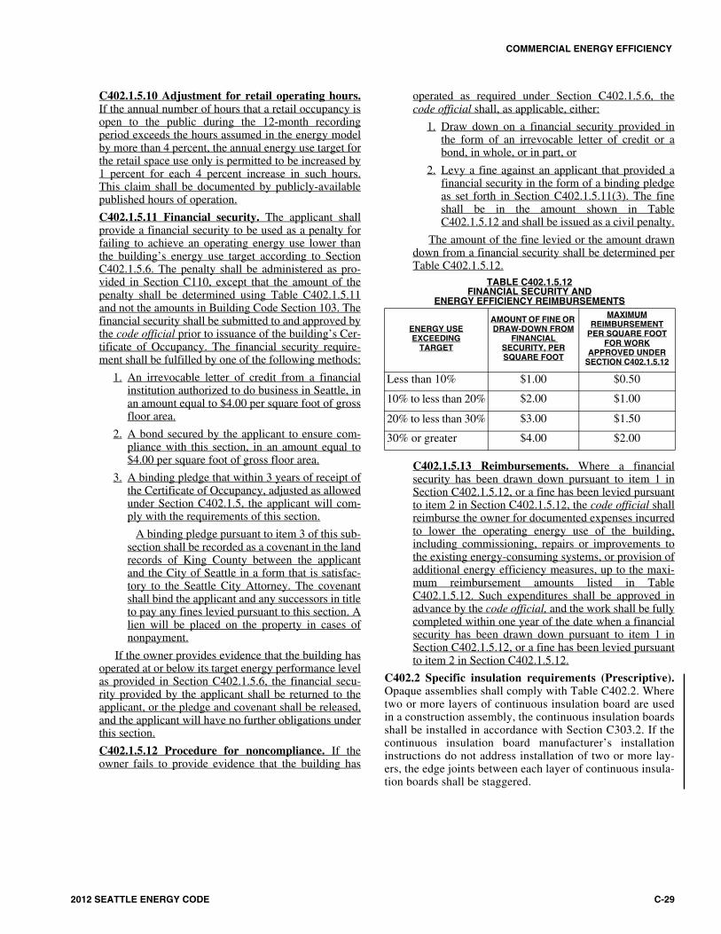
EQUATION C402-1TARGET UAt
(continued)
UAt = UradtAradt + UmrtAmrt + UratArat + Umwt(Amwt + Amwbgt) + Umbwt(Ambwt + Ambwbgt) + Usfwt(Asfwt + Asfwbgt) + Uwfwt(Awfwt + Awfwbgt)+ UfmtAfmt + UfjtAfjt + FstPst + FsrtPsrt + UdstAdst + UdrtAdrt + UvgtAvgt + UvgmtAvgmt + UvgmotAvgmot + UvgdtAvgdt + UogtAogt
UAt = The target combined specific heat transfer of the gross roof/ceiling assembly, exterior wall and floor area.
where:
Uradt = The thermal transmittance value for roofs with the insulation entirely above deck found in Table C402.1.2.
Umrt = The thermal transmittance value for metal building roofs found in Table C402.1.2.
Urat = The thermal transmittance value for attic and other roofs found in Table C402.1.2.
Umwt = The thermal transmittance value for opaque mass walls found in Table C402.1.2.
Umbwt = The thermal transmittance value for opaque metal building walls found in Table C402.1.2.
Usfwt = The thermal transmittance value for opaque steel-framed walls found in Table C402.1.2.
Uwfwt = The thermal transmittance value for opaque wood framed and other walls found in Table C402.1.2.
Ufmt = The thermal transmittance value for mass floors over unconditioned space found in Table C402.1.2.
Ufjt = The thermal transmittance value for joist floors over unconditioned space found in Table C402.1.2.
Fst = The F-factor for slab-on-grade floors found in Table C402.1.2.
Fsrt = The F-factor for radiant slab floors found in Table C402.1.2.
Udst = The thermal transmittance value for opaque swinging doors found in Table C402.2.
Udrt = The thermal transmittance value for opaque roll-up or sliding doors found in Table C402.2.
Uvgt =The thermal transmittance value for vertical fenestration with nonmetal framing found in Table C402.3 which corre-sponds to the proposed vertical fenestration area as a percent of gross exterior wall area. *Buildings utilizing Section C402.3.1.3 shall use the thermal transmittance value specified there.
Uvgmt =The thermal transmittance value for vertical fenestration with fixed metal framing found in Table C402.3 which corre-sponds to the proposed vertical fenestration area as a percent of gross exterior wall area. *Buildings utilizing Section C402.3.1.3 shall use the thermal transmittance value specified there.
Uvgmot =The thermal transmittance value for vertical fenestration with operable metal framing found in Table C402.3 which cor-responds to the proposed vertical fenestration area as a percent of gross exterior wall area. *Buildings utilizing Section C402.3.1.3 shall use the thermal transmittance value specified there.
Uvgdt =The thermal transmittance value for entrance doors found in Table C402.3 which corresponds to the proposed vertical fenestration area as a percent of gross exterior wall area. *Buildings utilizing Section C402.3.1.3 shall use the thermal transmittance value specified there.
Uogt =The thermal transmittance for skylights found in Table C402.3 which corresponds to the proposed skylight area as a per-cent of gross exterior roof area.
Afmt = The proposed mass floor over unconditioned space area, Afm
Afjt = The proposed joist floor over unconditioned space area, Afj
Pst = The proposed linear feet of slab-on-grade floor perimeter, Ps
Psrt = The proposed linear feet of radiant slab floor perimeter, Prs
Adst = The proposed opaque swinging door area, Ads
Adrt = The proposed opaque roll-up or sliding door area, Adr
and
If the vertical fenestration area as a percent of gross exterior above-grade wall area does not exceed the maximum allowed in Section C402.3.1:
Amwt = The proposed opaque above grade mass wall area.
Ambwt = The proposed opaque above grade metal building wall area.
Asfwt = The proposed opaque above grade steel framed wall area.
Awfwt = The proposed opaque above grade wall wood framed and other area.
COMMERCIAL ENERGY EFFICIENCY
2012 SEATTLE ENERGY CODE C-31
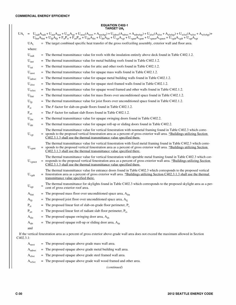
EQUATION C402-1—continuedTARGET UAT
Avgt = The proposed vertical fenestration area with nonmetal framing.
Avgmt = The proposed vertical fenestration area with fixed metal framing.
Avgmot = The proposed vertical fenestration area with operable metal framing.
Avgdt = The proposed entrance door area.
or
If the vertical fenestration area as a percent of gross above-grade exterior wall area exceeds the maximum allowed in Section C402.3.1, the area of each vertical fenestration element shall be reduced in the base envelope design by the same percentage and the net area of each above-grade wall type increased proportionately by the same percentage so that the total vertical fenestration area is exactly equal to the allowed per-centage per Section C402.3.1 of the gross above-grade wall area.
and
If the skylight area as a percent of gross exterior roof area does not exceed the maximum allowed in Section C402.3.1:
Aradt = The proposed roof area with insulation entirely above the deck, Arad
Amrt = The proposed roof area for metal buildings, Amr
Arat = The proposed attic and other roof area, Aor
Aogat = The proposed skylight area, Aogor
or
If the skylight area as a percent of gross exterior roof area exceeds the maximum allowed in Section C402.3.1, the area of each skylight ele-ment shall be reduced in the base envelope design by the same percentage and the net area of each roof type increased proportionately by the same percentage so that the total skylight area is exactly equal to the allowed percentage per Section C402.3.1 of the gross roof area.
*NOTE: The vertical fenestration area does not include opaque doors and opaque spandrel panels.

COMMERCIAL ENERGY EFFICIENCY
C-32 2012 SEATTLE ENERGY CODE
EQUATION C402-2PROPOSED UAP
UAp = UradArad + UmrAmr + UraAra + UmwAmw + UmbwAmbw + UsfwAsfw + UwfowAwfow + UfmAfm + UfjAfj + FsPs + FsrPsr + UdsAds + UdrAdr + UvgAvg + UvgmfAvgmf + UvgmoAvgmo + UvgdAvgd + UogAog
where:
UAp = The combined proposed specific heat transfer of the gross exterior wall, floor and roof/ceiling assembly area.
Urad = The thermal transmittance of the roof area where the insulation is entirely above the roof deck.
Arad = Opaque roof area where the insulation is entirely above the roof deck.
Umr = The thermal transmittance of the metal building roof area.
Amr = Opaque metal building roof area.
Ura = The thermal transmittance of the roof over attic and other roof area.
Ara = Opaque roof over attic and other roof area.
Umw = The thermal transmittance of the opaque mass wall area.
Amw = Opaque mass wall area (not including opaque doors).
Umbw = The thermal transmittance of the opaque metal building wall area.
Ambw = Opaque metal building wall area (not including opaque doors).
Usfw = The thermal transmittance of the opaque steel framed wall area.
Asfw = Opaque steel framed wall area (not including opaque doors).
Uwfw = The thermal transmittance of the opaque wood framed and other wall area.
Awfw = Opaque wood framed and other wall area (not including opaque doors).
Ufm = The thermal transmittance of the mass floor over unconditioned space area.
Afm = Mass floor area over unconditioned space.
Ufj = The thermal transmittance of the joist floor over unconditioned space area.
Afj = Joist floor area over unconditioned space.
Fs = Slab-on-grade floor component F-factor.
Ps = Linear feet of slab-on-grade floor perimeter.
Fsr = Radiant floor component F-factor.
Psr = Lineal feet of radiant floor perimeter.
Uds = The thermal transmittance value of the opaque swinging door area.
Ads = Opaque swinging door area.
Udr = The thermal transmittance value of the opaque roll-up or sliding door area.
Adr = Opaque roll-up or sliding door area.
Uvg = The thermal transmittance of the vertical fenestration area with nonmetal framing.*
Avg = Vertical fenestration area with nonmetal framing.*
Uvgmf = The thermal transmittance of the vertical fenestration area with fixed metal framing.*
Avgmf = Vertical fenestration area with fixed metal framing.*
Uvgmo = The thermal transmittance of the vertical fenestration area with operable metal framing.*
Avgmo = Vertical fenestration area with operable metal framing.*
Uvgd = The thermal transmittance of the vertical fenestration area for entrance doors.*
Avgd = Vertical fenestration area for entrance doors.*
Uog = The thermal transmittance for the skylights.
Aog = Skylight area.
NOTE: Where more than one type of wall, window, roof/ceiling, door and skylight is used, the U and A terms for those items shall be expanded into subelements as:
Umw1Amw1 + Umw2Amw2 + Usfw1Asfw1 + ...etc.
*NOTE: The vertical fenestration area does not include opaque doors and opaque spandrel panels.

COMMERCIAL ENERGY EFFICIENCY
2012 SEATTLE ENERGY CODE C-33
EQUATION C402-3TARGET SHGCAt
NOTES: Buildings utilizing Section C402.3.1.3 shall use the SHGC value specified there. The SHGC may be adjusted for projection factors per therequirements of C402.3.3.
SHGCAt = SHGCt(Aogt + Avgt + Avgmt + Avgmot + Avgdt)
where:
SHGCAt = The target combined ((specific)) solar heat gain coefficient of the target fenestration area.
SHGCogt = The solar heat gain coefficient for skylight fenestration found in Table C402.3 and Aogt as defined in Equation C402-1.
SHGCvgt = The solar heat gain coefficient for vertical fenestration found in Table C402.3 and Avgt, Avgmt, Avgmot and Avgdt as defined in Equation C402-1.
EQUATION C402-4PROPOSED SHGCAP
SHGCAp = SHGCogAog + SHGCvgAvg
where:
SHGCAt = The combined proposed ((specific)) solar heat gain coefficient of the proposed fenestration area.
SHGCog = The solar heat gain coefficient of the skylights.
Aog = The skylight area.
SHGCvg = The solar heat gain coefficient of the vertical fenestration.
Avg = The vertical fenestration area.
NOTE: The vertical fenestration area does not include opaque doors and opaque spandrel panels.
TABLE C402.2OPAQUE THERMAL ENVELOPE REQUIREMENTSa, f
For SI: 1 inch = 25.4 mm, ci = Continuous insulation, NR = No requirement.LS = Liner system - A continuous membrane installed below the purlins and uninterrupted by framing members. Uncompressed, unfaced insulation rests on top
of the membrane between the purlins.(continued)
CLIMATE ZONE5 AND MARINE 4 (SEATTLE)
All Other Group RRoofs
Insulation entirely above deck ((R-30ci)) R-38ci R-38ciMetal buildings (with R-3.5 thermal blocks)a, b ((R-25 + R-11 LS)) R-25 + R-22 LS ((R-25 + R-11 LS)) R-25 + R-22 LSAttic and other R-49 R-49
Walls, Above Grade
Mass
((R-9.5ci))Exterior: R-16 c.i.
Interior: R-13 + R-6 ci wood stud, orR-13 + R-10 ci metal stud
((R-13.3ci))Exterior: R-16 c.i.
Interior: R-13 + R-6 ci wood stud, orR-13 + R-10 ci metal stud
Metal building R-13 + R-13ci R-13 + R-13ciSteel framed R-13 + R-10ci R-19 + R-8.5ciWood framed and other ((R-21 int)) R-13 + R-7.5 ci R-21 int
Walls, Below Grade
Below-grade walld
((Same as above grade))Exterior: R-10 ci
Interior: R-19 wood stud, orR-13 + R-6 ci metal stud
((Same as above grade))Exterior: R-10 ci
Interior: R-19 wood stud, orR-13 + R-6 ci metal stud
Floors
Mass R-30ci R-30ci
Joist/framing((R-30e))
Steel frame: R-38 + R-4 ciWood frame: R-38
((R-30e))Steel frame: R-38 + R-4 ci
Wood frame: R-38Slab-on-Grade Floors
Unheated slabs R-10 for 24 below R-10 for 24 belowHeated slabsd R-10 perimeter & under entire slab R-10 perimeter & under entire slab
Opaque Doors
Swinging U-0.37 U-0.37Roll-up or sliding ((R-4.75)) U-0.390 ((R-4.75)) U-0.390
COMMERCIAL ENERGY EFFICIENCY
C-34 2012 SEATTLE ENERGY CODE
TABLE C402.2OPAQUE THERMAL ENVELOPE REQUIREMENTSa, f—continued
a. Assembly descriptions can be found in Chapter 2 and Appendix A.b. Where using R-value compliance method, a thermal spacer block shall be provided, otherwise use the U-factor compliance method in Table C402.1.2.c. Reserved. ((Exception: Integral insulated concrete block walls complying with ASTM C 90 with all cores filled and meeting both of the following:
1. At least 50 percent of cores must be filled with vermiculite or equivalent fill insulation; and 2. The building thermal envelope encloses one or more of the following uses: Warehouse (storage and retail), gymnasium, auditorium, church chapel, arena,
kennel, manufacturing plant, indoor swimming pool, pump station, water and waste water treatment facility, storage facility, storage area, motor vehicleservice facility. Where additional uses not listed (such as office, retail, etc.) are contained within the building, the exterior walls that enclose these areasmay not utilize this exception and must comply with the appropriate mass wall R-value from Table C402.2 or U-factor from Table C402.1.2.))
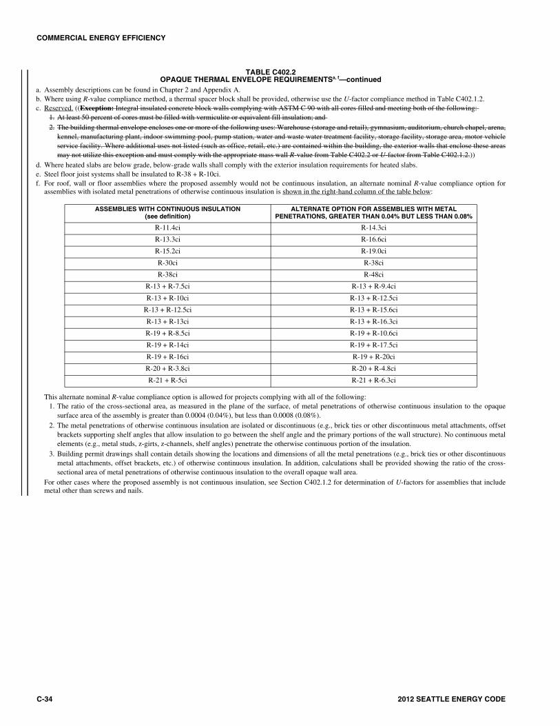
d. Where heated slabs are below grade, below-grade walls shall comply with the exterior insulation requirements for heated slabs.e. Steel floor joist systems shall be insulated to R-38 + R-10ci.f. For roof, wall or floor assemblies where the proposed assembly would not be continuous insulation, an alternate nominal R-value compliance option for
assemblies with isolated metal penetrations of otherwise continuous insulation is shown in the right-hand column of the table below:
This alternate nominal R-value compliance option is allowed for projects complying with all of the following:1. The ratio of the cross-sectional area, as measured in the plane of the surface, of metal penetrations of otherwise continuous insulation to the opaque
surface area of the assembly is greater than 0.0004 (0.04%), but less than 0.0008 (0.08%).2. The metal penetrations of otherwise continuous insulation are isolated or discontinuous (e.g., brick ties or other discontinuous metal attachments, offset
brackets supporting shelf angles that allow insulation to go between the shelf angle and the primary portions of the wall structure). No continuous metalelements (e.g., metal studs, z-girts, z-channels, shelf angles) penetrate the otherwise continuous portion of the insulation.
3. Building permit drawings shall contain details showing the locations and dimensions of all the metal penetrations (e.g., brick ties or other discontinuousmetal attachments, offset brackets, etc.) of otherwise continuous insulation. In addition, calculations shall be provided showing the ratio of the cross-sectional area of metal penetrations of otherwise continuous insulation to the overall opaque wall area.
For other cases where the proposed assembly is not continuous insulation, see Section C402.1.2 for determination of U-factors for assemblies that includemetal other than screws and nails.
ASSEMBLIES WITH CONTINUOUS INSULATION(see definition)
ALTERNATE OPTION FOR ASSEMBLIES WITH METAL PENETRATIONS, GREATER THAN 0.04% BUT LESS THAN 0.08%
R-11.4ci R-14.3ci
R-13.3ci R-16.6ci
R-15.2ci R-19.0ci
R-30ci R-38ci
R-38ci R-48ci
R-13 + R-7.5ci R-13 + R-9.4ci
R-13 + R-10ci R-13 + R-12.5ci
R-13 + R-12.5ci R-13 + R-15.6ci
R-13 + R-13ci R-13 + R-16.3ci
R-19 + R-8.5ci R-19 + R-10.6ci
R-19 + R-14ci R-19 + R-17.5ci
R-19 + R-16ci R-19 + R-20ci
R-20 + R-3.8ci R-20 + R-4.8ci
R-21 + R-5ci R-21 + R-6.3ci

COMMERCIAL ENERGY EFFICIENCY
2012 SEATTLE ENERGY CODE C-35
C402.2.1 Roof assembly. The minimum thermal resistance(R-value) of the insulating material installed either betweenthe roof framing or continuously on the roof assembly shallbe as specified in Table C402.2, based on constructionmaterials used in the roof assembly. Skylight curbs shallbe insulated to the level of roofs with insulation entirelyabove deck or R-5, whichever is less.
Exceptions:
1. Continuously insulated roof assemblies where thethickness of insulation varies 1 inch (25 mm) orless and where the area-weighted U-factor isequivalent to the same assembly with the R-valuespecified in Table C402.2.
2. Unit skylight curbs included as a component ofan NFRC 100 rated assembly shall not berequired to be insulated.
Insulation installed on a suspended ceiling with remov-able ceiling tiles shall not be considered part of the mini-mum thermal resistance of the roof insulation.
C402.2.1.1 Roof solar reflectance and thermalemittance. Low-sloped roofs, with a slope less than 2units vertical in 12 horizontal, directly above cooledconditioned spaces in Climate Zones 1, 2, and 3 shallcomply with one or more of the options in TableC402.2.1.1.
Exceptions: The following roofs and portions ofroofs are exempt from the requirements in TableC402.2.1.1:
1. Portions of roofs that include or are coveredby:
1.1. Photovoltaic systems or components.
1.2. Solar air or water heating systems orcomponents.
1.3. Roof gardens or landscaped roofs.
1.4. Above-roof decks or walkways.
1.5. Skylights.
1.6. HVAC systems, components, andother opaque objects mounted abovethe roof.
2. Portions of roofs shaded during the peak sunangle on the summer solstice by permanentfeatures of the building, or by permanent fea-tures of adjacent buildings.
3. Portions of roofs that are ballasted with a min-imum stone ballast of 17 pounds per squarefoot (psf) (74 kg/m2) or 23 psf (117 kg/m2)pavers.
4. Roofs where a minimum of 75 percent of theroof area meets a minimum of one of theexceptions above.
C402.2.2 Classification of walls. Walls associated withthe building envelope shall be classified in accordancewith Section C202.
C402.2.3 Thermal resistance of above-grade walls. Theminimum thermal resistance (R-value) of the insulatingmaterials installed in the wall cavity between the framingmembers and continuously on the walls shall be as specifiedin Table C402.2, based on framing type and constructionmaterials used in the wall assembly. The R-value of integralinsulation installed in concrete masonry units (CMU) shallnot be used in determining compliance with Table C402.2.
“Mass walls” shall include walls weighing not less than:
1. 35 psf (170 kg/m2) of wall surface area; or
2. 25 psf (120 kg/m2) of wall surface area if the mate-rial weight is not more than 120 pounds per cubicfoot (pcf) (1900 kg/m3).
C402.2.4 Thermal resistance of below-grade walls. Theminimum thermal resistance (R-value) of the insulatingmaterial installed in, or continuously on, the below-gradewalls shall be as specified in Table C402.2.
C402.2.5 Floors over outdoor air or unconditionedspace. The minimum thermal resistance (R-value) of theinsulating material installed either between the floor fram-ing or continuously on the floor assembly shall be as spec-ified in Table C402.2, based on construction materialsused in the floor assembly.
“Mass floors” shall include floors weighing not less than:
1. 35 psf (170 kg/m2) of floor surface area; or
2. 25 psf (120 kg/m2) of floor surface area if the mate-rial weight is not more than 120 pcf (1900 kg/m3).
Informative Note: The section below regarding roof solarreflectance does not apply to Washington State, as it refersonly to Climate Zones 1, 2 and 3. Seattle is in Zone 4.
TABLE C402.2.1.1MINIMUM ROOF REFLECTANCE AND EMITTANCE OPTIONSa
a. The use of area-weighted averages to meet these requirements shall bepermitted. Materials lacking initial tested values for either solarreflectance or thermal emittance, shall be assigned both an initial solarreflectance of 0.10 and an initial thermal emittance of 0.90. Materialslacking three-year aged tested values for either solar reflectance orthermal emittance shall be assigned both a three-year aged solarreflectance of 0.10 and a three-year aged thermal emittance of 0.90.
b. Solar reflectance tested in accordance with ASTM C 1549, ASTM E 903or ASTM E 1918.
c. Thermal emittance tested in accordance with ASTM C 1371 or ASTM E408.
d. Solar reflectance index (SRI) shall be determined in accordance withASTM E 1980 using a convection coefficient of 2.1 Btu/h × ft2 ×°F(12W/m2 × K). Calculation of aged SRI shall be based on aged testedvalues of solar reflectance and thermal emittance. Calculation of initialSRI shall be based on initial tested values of solar reflectance andthermal emittance.
Three-year aged solar reflectanceb of 0.55 and three-year aged ther-mal emittancec of 0.75
Initial solar reflectanceb of 0.70 and initial thermal emittancec of 0.75
Three-year-aged solar reflectance indexd of 64
Initial solar reflectance indexd of 82
>
>
COMMERCIAL ENERGY EFFICIENCY
C-36 2012 SEATTLE ENERGY CODE
C402.2.6 Slabs on grade. Where the slab on grade is incontact with the ground, the minimum thermal resistance(R-value) of the insulation around the perimeter of unheatedor heated slab-on-grade floors and under the entire slab ofheated slab-on-grade floors shall be as specified in TableC402.2. The insulation shall be placed on the outside of thefoundation or on the inside of the foundation wall. The insu-lation shall extend downward from the top of the slab for aminimum distance as shown in the table or to the top of thefooting, whichever is less, or downward to at least the bot-tom of the slab and then horizontally to the interior or exte-rior for the total distance shown in the table. Insulationextending away from the building shall be protected bypavement or by a minimum of 10 inches (254 mm) of soil.
Exception: Where the slab-on-grade floor is greaterthan 24 inches (61 mm) below the finished exteriorgrade, perimeter insulation is not required.
C402.2.7 Opaque doors. Opaque doors (doors having lessthan 50 percent glass area) shall meet the applicable require-ments for doors as specified in Table C402.2 and be consid-ered as part of the gross area of above-grade walls that arepart of the building envelope.
C402.2.8 Insulation of radiant heating systems. Radiantpanels, and associated U-bends and headers, designed forsensible heating of an indoor space through heat transferfrom the thermally effective panel surfaces to the occu-pants or indoor space by thermal radiation and natural con-vection and the bottom surfaces of floor structuresincorporating radiant heating shall be insulated with aminimum of R-3.5 (0.62 m2/K × W). Adjacent envelopeinsulation counts towards this requirement.
C402.3 Fenestration (Prescriptive). Fenestration shallcomply with Table C402.3. Automatic daylighting controlsspecified by this section shall comply with SectionC405.2.2.3.2.
Exception: Single glazing is permitted for security pur-poses and for revolving doors, provided that the total areaof single glazing does not exceed 1 percent of the grossexterior wall area, and such glazing is included in the per-centage of the total glazing area, U-factor and SHGCrequirements in Section C402.3.
C402.3.1 Maximum area. The vertical fenestration area (notincluding opaque doors and opaque spandrel panels) shallnot exceed 30 percent of the gross above-grade wall area. The skylight area shall not exceed ((3)) 5 percent of the grossroof area.
Exception: For vertical fenestration at street levelretail or for other occupancies where the Seattle LandUse Code requires street-level transparency, the fenes-tration area shall not exceed 75 percent of the area ofthe street-level wall that faces the street or that adjoinsother pedestrian areas used for retail access. For thepurposes of this exception, the street-level wall shall bemeasured from the street-level floor to the interior ceil-ing level or to 20 feet above floor level, whichever islowest. When this exception is utilized, separate calcu-lations shall be performed for these sections of thebuilding envelope, and these values shall not be aver-
aged with any others for compliance purposes. On thestreet level the 75 percent fenestration area is permittedto be exceeded, if the additional fenestration area isdeducted from fenestration allowances for other areasof the building.
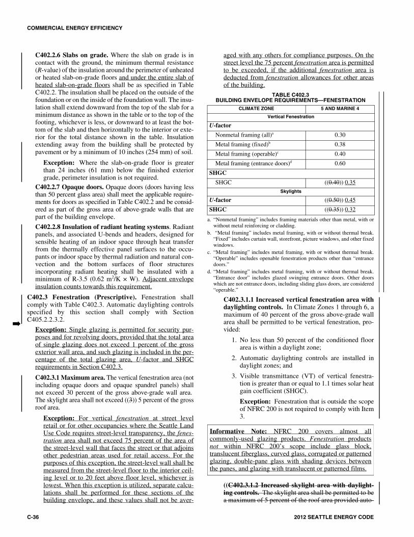
TABLE C402.3BUILDING ENVELOPE REQUIREMENTS—FENESTRATION
a. “Nonmetal framing” includes framing materials other than metal, with orwithout metal reinforcing or cladding.
b. “Metal framing” includes metal framing, with or without thermal break.“Fixed” includes curtain wall, storefront, picture windows, and other fixedwindows.
c. “Metal framing” includes metal framing, with or without thermal break.“Operable” includes openable fenestration products other than “entrancedoors.”
d. “Metal framing” includes metal framing, with or without thermal break.“Entrance door” includes glazed swinging entrance doors. Other doorswhich are not entrance doors, including sliding glass doors, are considered“operable.”
C402.3.1.1 Increased vertical fenestration area withdaylighting controls. In Climate Zones 1 through 6, amaximum of 40 percent of the gross above-grade wallarea shall be permitted to be vertical fenestration, pro-vided:
1. No less than 50 percent of the conditioned floorarea is within a daylight zone;
2. Automatic daylighting controls are installed indaylight zones; and
3. Visible transmittance (VT) of vertical fenestra-tion is greater than or equal to 1.1 times solar heatgain coefficient (SHGC).
Exception: Fenestration that is outside the scopeof NFRC 200 is not required to comply with Item3.
((C402.3.1.2 Increased skylight area with daylight-ing controls. The skylight area shall be permitted to bea maximum of 5 percent of the roof area provided auto-
�
CLIMATE ZONE 5 AND MARINE 4
Vertical Fenestration
U-factor
Nonmetal framing (all)a 0.30
Metal framing (fixed)b 0.38
Metal framing (operable)c 0.40
Metal framing (entrance doors)d 0.60
SHGC
SHGC ((0.40)) 0.35
Skylights
U-factor ((0.50)) 0.45
SHGC ((0.35)) 0.32
Informative Note: NFRC 200 covers almost allcommonly-used glazing products. Fenestration productsnot within NFRC 200’s scope include glass block,translucent fiberglass, curved glass, corrugated or patternedglazing, double-pane glass with shading devices betweenthe panes, and glazing with translucent or patterned films.

COMMERCIAL ENERGY EFFICIENCY
2012 SEATTLE ENERGY CODE C-37
matic daylighting controls are installed in daylightzones under skylights.))
C402.3.1.2((3)) Increased vertical fenestration areawith high-performance fenestration. The verticalfenestration area (not including opaque doors andopaque spandrel panels) is permitted to exceed 30 per-cent but shall not exceed 40 percent of the gross abovegrade wall area, for the purpose of prescriptive compli-ance with Section C402.1.2 or for the Target UA calcu-lation in Equation C402-1 or C402-5, provided thateach of the following conditions are met:
1. The vertical fenestration shall have the followingmaximum U-factors:
a. Nonmetal framing (all) = 0.28
b. Metal framing (fixed) = ((0.34)) 0.36
c. Metal framing (operable) = 0.36
d. Metal framing (entrance doors) = 0.60
An area-weighted average shall be permitted tosatisfy the U-factor requirements for each fenestra-tion product category listed above. Individual fenes-tration products from different fenestration productcategories shall not be combined in calculating thearea-weighted average U-factor.
2. The SHGC of the vertical fenestration shall beless than or equal to 0.35, adjusted for projectionfactor in compliance with C402.3.3.1.
The compliance path described in this sectionC402.3.1.3 is not permitted to be used for the TotalBuilding Performance compliance path as set out inSection C407.
C402.3.2 Minimum skylight fenestration area. For sin-gle-story buildings only, in an enclosed space greater than10,000 square feet (929 m2), directly under a roof withceiling heights greater than 15 feet (4572 mm), and usedas an office, lobby, atrium, concourse, corridor, gymna-sium/exercise center, convention center, automotive ser-vice, manufacturing, nonrefrigerated warehouse, retailstore, distribution/sorting area, transportation, or work-shop, the total daylight zone under skylights shall be notless than half the floor area and shall provide a minimumskylight area to daylight zone under skylights of either:
1. Not less than 3 percent with a skylight VT of at least0.40; or
2. Provide a minimum skylight effective aperture of atleast 1 percent determined in accordance with Equa-tion C4-1.
(Equation C4-1)
where:
Skylight area = Total fenestration area ofskylights.
Skylight VT = Area weighted average visibletransmittance of skylights.
WF = Area weighted average wellfactor, where well factor is 0.9if light well depth is less than 2feet (610 mm), or 0.7 if lightwell depth is 2 feet (610 mm) orgreater.
Light well depth = Measure vertically from theunderside of the lowest point ofthe skylight glazing to theceiling plane under theskylight.
Exception: Skylights above daylight zones of enclosedspaces are not required in:
1. Buildings in climate zones 6 through 8.
2. Spaces where the designed general lighting powerdensities are less than 0.5 W/ft2 (5.4 W/m2).
3. Areas where it is documented that existing struc-tures or natural objects block direct beam sun-light on at least half of the roof over the enclosedarea for more than 1,500 daytime hours per yearbetween 8 am and 4 pm.
4. Spaces where the daylight zone under rooftopmonitors is greater than 50 percent of theenclosed space floor area.
C402.3.2.1 Lighting controls in daylight zones underskylights. All lighting in the daylight zone shall becontrolled by automatic daylighting controls that com-ply with Section C405.2.2.3.2.
((Exception: Skylights above daylight zones ofenclosed spaces are not required in:
1. Buildings in Climate Zones 6 through 8.
2. Spaces where the designed general lightingpower densities are less than 0.5 W/ft2 (5.4 W/m2).
3. Areas where it is documented that existingstructures or natural objects block direct beamsunlight on at least half of the roof over theenclosed area for more than 1,500 daytimehours per year between 8 am and 4 pm.
4. Spaces where the daylight zone under rooftopmonitors is greater than 50 percent of theenclosed space floor area.))
C402.3.2.2 Haze factor. Skylights in office, storage,automotive service, manufacturing, nonrefrigeratedwarehouse, retail store, and distribution/sorting areaspaces shall have a glazing material or diffuser with ameasured haze factor greater than 90 percent whentested in accordance with ASTM D 1003.
Exception: Skylights designed to exclude directsunlight entering the occupied space by the use offixed or automated baffles, or the geometry of sky-light and light well need not comply with SectionC402.3.2.2.
C402.3.3 Maximum U-factor and SHGC. For verticalfenestration, the maximum U-factor and solar heat gain
141414
Skylight Effective Aperture = 0.85 Skylight Area Skylight VT WF×××Daylight zone under skylight
-------------------------------------------------------------------------------------------------------
COMMERCIAL ENERGY EFFICIENCY
C-38 2012 SEATTLE ENERGY CODE
coefficient (SHGC) shall be as specified in Table C402.3,based on the window projection factor. For skylights, themaximum U-factor and solar heat gain coefficient (SHGC)shall be as specified in Table C402.3.
The window projection factor shall be determined inaccordance with Equation C4-2.
PF = A/B (Equation C4-2)
where:
PF= Projection factor (decimal).
A = Distance measured horizontally from the furthestcontinuous extremity of any overhang, eave, orpermanently attached shading device to the verticalsurface of the glazing.
B = Distance measured vertically from the bottom of theglazing to the underside of the overhang, eave, orpermanently attached shading device.
Where different windows or glass doors have differentPF values, they shall each be evaluated separately.
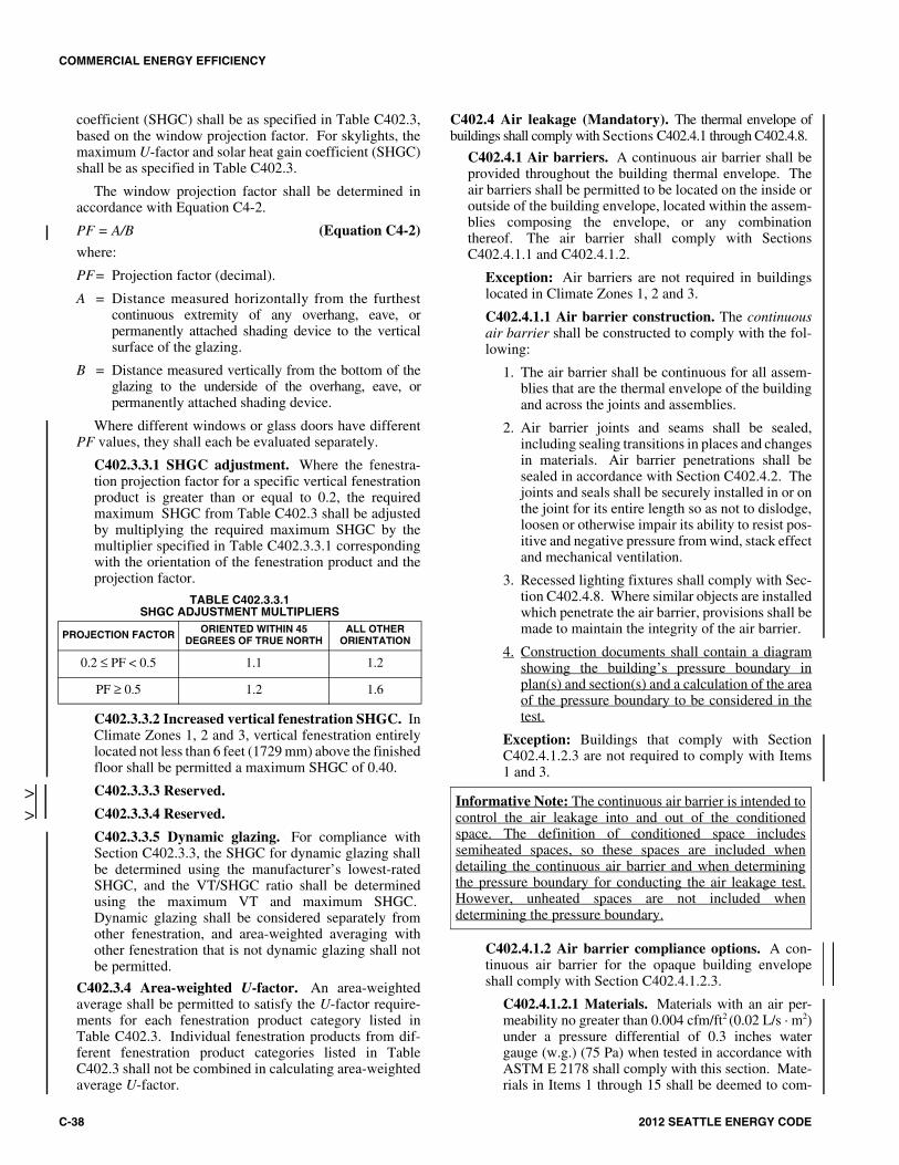
C402.3.3.1 SHGC adjustment. Where the fenestra-tion projection factor for a specific vertical fenestrationproduct is greater than or equal to 0.2, the requiredmaximum SHGC from Table C402.3 shall be adjustedby multiplying the required maximum SHGC by themultiplier specified in Table C402.3.3.1 correspondingwith the orientation of the fenestration product and theprojection factor.
TABLE C402.3.3.1SHGC ADJUSTMENT MULTIPLIERS
C402.3.3.2 Increased vertical fenestration SHGC. InClimate Zones 1, 2 and 3, vertical fenestration entirelylocated not less than 6 feet (1729 mm) above the finishedfloor shall be permitted a maximum SHGC of 0.40.
C402.3.3.3 Reserved.
C402.3.3.4 Reserved.
C402.3.3.5 Dynamic glazing. For compliance withSection C402.3.3, the SHGC for dynamic glazing shallbe determined using the manufacturer’s lowest-ratedSHGC, and the VT/SHGC ratio shall be determinedusing the maximum VT and maximum SHGC. Dynamic glazing shall be considered separately fromother fenestration, and area-weighted averaging withother fenestration that is not dynamic glazing shall notbe permitted.
C402.3.4 Area-weighted U-factor. An area-weightedaverage shall be permitted to satisfy the U-factor require-ments for each fenestration product category listed inTable C402.3. Individual fenestration products from dif-ferent fenestration product categories listed in TableC402.3 shall not be combined in calculating area-weightedaverage U-factor.
C402.4 Air leakage (Mandatory). The thermal envelope ofbuildings shall comply with Sections C402.4.1 through C402.4.8.
C402.4.1 Air barriers. A continuous air barrier shall beprovided throughout the building thermal envelope. Theair barriers shall be permitted to be located on the inside oroutside of the building envelope, located within the assem-blies composing the envelope, or any combinationthereof. The air barrier shall comply with SectionsC402.4.1.1 and C402.4.1.2.
Exception: Air barriers are not required in buildingslocated in Climate Zones 1, 2 and 3.
C402.4.1.1 Air barrier construction. The continuousair barrier shall be constructed to comply with the fol-lowing:
1. The air barrier shall be continuous for all assem-blies that are the thermal envelope of the buildingand across the joints and assemblies.
2. Air barrier joints and seams shall be sealed,including sealing transitions in places and changesin materials. Air barrier penetrations shall besealed in accordance with Section C402.4.2. Thejoints and seals shall be securely installed in or onthe joint for its entire length so as not to dislodge,loosen or otherwise impair its ability to resist pos-itive and negative pressure from wind, stack effectand mechanical ventilation.
3. Recessed lighting fixtures shall comply with Sec-tion C402.4.8. Where similar objects are installedwhich penetrate the air barrier, provisions shall bemade to maintain the integrity of the air barrier.
4. Construction documents shall contain a diagramshowing the building’s pressure boundary inplan(s) and section(s) and a calculation of the areaof the pressure boundary to be considered in thetest.
Exception: Buildings that comply with SectionC402.4.1.2.3 are not required to comply with Items1 and 3.
C402.4.1.2 Air barrier compliance options. A con-tinuous air barrier for the opaque building envelopeshall comply with Section C402.4.1.2.3.
C402.4.1.2.1 Materials. Materials with an air per-meability no greater than 0.004 cfm/ft2 (0.02 L/s · m2)under a pressure differential of 0.3 inches watergauge (w.g.) (75 Pa) when tested in accordance withASTM E 2178 shall comply with this section. Mate-rials in Items 1 through 15 shall be deemed to com-
PROJECTION FACTOR ORIENTED WITHIN 45 DEGREES OF TRUE NORTH
ALL OTHER ORIENTATION
0.2 ≤ PF < 0.5 1.1 1.2
PF ≥ 0.5 1.2 1.6
>>
Informative Note: The continuous air barrier is intended tocontrol the air leakage into and out of the conditionedspace. The definition of conditioned space includessemiheated spaces, so these spaces are included whendetailing the continuous air barrier and when determiningthe pressure boundary for conducting the air leakage test.However, unheated spaces are not included whendetermining the pressure boundary.

COMMERCIAL ENERGY EFFICIENCY
2012 SEATTLE ENERGY CODE C-39
ply with this section provided joints are sealed andmaterials are installed as air barriers in accordancewith the manufacturer’s instructions.
1. Plywood with a thickness of not less than 3/8inch (10 mm).
2. Oriented strand board having a thickness ofnot less than 3/8 inch (10 mm).
3. Extruded polystyrene insulation board hav-ing a thickness of not less than 1/2 inch (12mm).
4. Foil-back polyisocyanurate insulation boardhaving a thickness of not less than 1/2 inch(12 mm).
5. Closed cell spray foam a minimum densityof 1.5 pcf (2.4 kg/m3) having a thickness ofnot less than 11/2 inches (36 mm).
6. Open cell spray foam with a densitybetween 0.4 and 1.5 pcf (0.6 and 2.4 kg/m3)and having a thickness of not less than 4.5inches (113 mm).
7. Exterior or interior gypsum board having athickness of not less than 1/2 inch (12 mm).
8. Cement board having a thickness of notless than 1/2 inch (12 mm).
9. Built up roofing membrane.
10. Modified bituminous roof membrane.
11. Fully adhered single-ply roof membrane.
12. A Portland cement/sand parge, or gypsumplaster having a thickness of not less than 5/8inch (16 mm).
13. Cast-in-place and precast concrete.
14. Fully grouted concrete block masonry.
15. Sheet steel or aluminum.
C402.4.1.2.2 Assemblies. Assemblies of materialsand components with an average air leakage not toexceed 0.04 cfm/ft2 (0.2 L/s · m2) under a pressuredifferential of 0.3 inches water gauge (w.g.)(75 Pa) when tested in accordance with ASTM E 2357,ASTM E 1677 or ASTM E 283 shall comply withthis section. Assemblies listed in Items 1 and 2 shallbe deemed to comply provided joints are sealed andrequirements of Section C402.4.1.1 are met.
1. Concrete masonry walls coated with oneapplication either of block filler and two appli-cations of a paint or sealer coating;
2. A Portland cement/sand parge, stucco or plas-ter minimum 1/2 inch (12 mm) in thickness.
C402.4.1.2.3 Building test. The completed buildingshall be tested and the air leakage rate of the buildingenvelope shall not exceed 0.40 cfm/ft2 at a pressuredifferential of 0.3 inches water gauge (2.0 L/s · m2 at 75Pa) at the upper 96 percent confidence interval in
accordance with ASTM E 779 or an equivalentmethod approved by the code official. A report thatincludes the tested surface area, floor area, air by vol-ume, stories above grade, and leakage rates shall besubmitted to the building owner and the code official.
The following modifications shall be made toASTM E 779:
1. Tests shall be accomplished using either (1)both pressurization and depressurization or (2)pressurization alone, but not depressurizationalone. If both pressurization and depressuriza-tion are not tested, the air leakage shall beplotted against the corrected P for pressuriza-tion in accordance with Section 9.4.
2. The test pressure range shall be from 25 Pa to80 Pa per Section 8.10, but the upper limitshall not be less than 50 Pa, and the differencebetween the upper and lower limit shall not beless than 25 Pa.
3. If the pressure exponent n is less than 0.45 orgreater than 0.85 per Section 9.6.4, the testshall be rerun with additional readings over alonger time interval.
If the tested rate exceeds that defined here, avisual inspection of the air barrier shall be con-ducted and any leaks noted shall be sealed to theextent practicable. An additional report identifyingthe corrective actions taken to seal air leaks shall besubmitted to the building owner and the code offi-cial and any further requirement to meet the leakageair rate will be waived.
C402.4.2 Air barrier penetrations. Penetrations of theair barrier and paths of air leakage shall be caulked, gas-keted or otherwise sealed in a manner compatible with theconstruction materials and location. Joints and seals shallbe sealed in the same manner or taped or covered with amoisture vapor-permeable wrapping material. Sealingmaterials shall be appropriate to the construction materialsbeing sealed. The joints and seals shall be securelyinstalled in or on the joint for its entire length so as not todislodge, loosen or otherwise impair its ability to resistpositive and negative pressure from wind, stack effect andmechanical ventilation.
C402.4.3 Air leakage of fenestration. The air leakage offenestration assemblies shall meet the provisions of TableC402.4.3. Testing shall be in accordance with the applica-ble reference test standard in Table C402.4.3 by an accred-ited, independent testing laboratory and labeled by themanufacturer.
Exceptions:
1. Field-fabricated fenestration assemblies that aresealed in accordance with Section C402.4.1. Afield-fabricated fenestration product is a fenestra-tion product (including glazed exterior doors)whose frame is made at the construction site ofstandard dimensional lumber or other materials
*
**

COMMERCIAL ENERGY EFFICIENCY
C-40 2012 SEATTLE ENERGY CODE
that were not previously cut, or otherwise formedwith the specific intention of being used to fabri-cate a fenestration product or exterior door.Field-fabricated does not include curtain walls.
2. Fenestration in buildings that comply with Sec-tion C402.4.1.2.3 are not required to meet the airleakage requirements in Table C402.4.3.
3. Custom exterior windows and doors manufac-tured by a small business provided they meet theapplicable provisions of Chapter 24 of the Inter-national Building Code. Once visual inspectionhas confirmed the presence of a gasket, operablewindows and doors manufactured by small busi-ness shall be permitted to be sealed off at theframe prior to the test.
TABLE C402.4.3MAXIMUM AIR INFILTRATION RATE FOR FENESTRATION ASSEMBLIES
For SI: 1 cubic foot per minute = 0.47 L/s, 1 square foot = 0.093 m2.a. The maximum rate for windows, sliding and swinging doors, and
skylights is permitted to be 0.3 cfm per square foot of fenestration or doorarea when tested in accordance with AAMA/WDMA/CSA101/I.S.2/A440at 6.24 psf (300 Pa).
C402.4.4 Doors and access openings to shafts, chutes,stairways, and elevator lobbies. Doors and access open-ings from conditioned space to shafts, chutes, stairways andelevator lobbies shall either meet the requirements of Sec-tion C402.4.3 or shall be gasketed, weatherstripped orsealed.
Exception: Door openings required to comply withSection 716 or 716.4 of the International BuildingCode; or doors and door openings required by the Inter-national Building Code to comply with UL 1784 shallnot be required to comply with Section C402.4.4.
C402.4.5 Air intakes, exhaust openings, stairways andshafts. Stairway enclosures and elevator shaft vents andother outdoor air intakes and exhaust openings integral tothe building envelope shall be provided with dampers inaccordance with Sections C402.4.5.1 and C402.4.5.2.
C402.4.5.1 Stairway and shaft vents. Stairway andshaft vents shall be provided with Class I motorizeddampers with a maximum leakage rate of 4 cfm/ft2
(20.3 L/s · m2) at 1.0 inch water gauge (w.g.) (249 Pa)when tested in accordance with AMCA 500D.
Stairway and shaft vent dampers shall be installedwith controls so that they are capable of automaticallyopening upon:
1. The activation of any fire alarm initiating deviceof the building’s fire alarm system; or
2. The interruption of power to the damper.
C402.4.5.2 Outdoor air intakes and exhausts. Out-door air supply, exhaust openings and relief outlets shallbe provided with Class IA motorized dampers whichclose automatically when the system is off. Return airdampers shall be equipped with motorized dampers.Dampers shall have a maximum leakage rate of 4 cfm/ft2
(20.3 L/s · m2) at 1.0 inch water gauge (w.g.) (249 Pa)when tested in accordance with AMCA 500D. Gravity(nonmotorized) dampers for ventilation air intakes shallbe protected from direct exposure to wind.
Exceptions:
1. Gravity (nonmotorized) dampers having a max-imum leakage rate of 20 cfm/ft2 (101.6 L/s · m2)at 1.0 inch water gauge (w.g.) (249 Pa) whentested in accordance with AMCA 500D are per-mitted to be used for relief, outside air andexhaust openings in buildings ((less than threestories in height above grade)) if equipmenthas less than ((5,000)) 300 cfm (((2.36)) 0.14m3/s) total supply flow.
2. Reserved. ((Gravity (nonmotorized) dampersfor ventilation air intakes shall be protectedfrom direct exposure to wind.))
3. Gravity dampers smaller than 24 inches (610mm) in either dimension shall be permitted tohave a leakage of 40 cfm/ft2 (203.2 L/s · m2) at1.0 inch water gauge (w.g.) (249 Pa) whentested in accordance with AMCA 500D.
4. Gravity (nonmotorized) dampers in Group Roccupancies where the design outdoor airintake, relief or exhaust capacity does notexceed ((400)) 300 cfm (((189)) 141 L/s).
5. Systems serving areas which require continu-ous operation.
6. Combustion air intakes.
7. Type I kitchen exhaust hoods.
C402.4.6 Loading dock weatherseals. Cargo doors andloading dock doors shall be equipped with weatherseals torestrict infiltration when vehicles are parked in the door-way.
C402.4.7 Vestibules. All building entrances shall be pro-tected with an enclosed vestibule, with all doors opening intoand out of the vestibule equipped with self-closing devices.
FENESTRATION ASSEMBLY MAXIMUM RATE (CFM/FT2) TEST PROCEDURE
Windows 0.20 a
AAMA/WDMA/CSA101/I.S.2/A440
orNFRC 400
Sliding doors 0.20 a
Swinging doors 0.20 a
Skylights – with conden-sation weepage openings 0.30
Skylights – all other 0.20 a
Curtain walls 0.06
NFRC 400 or
ASTM E 283 at 1.57 psf (75 Pa)
Storefront glazing 0.06
Commercial glazed swinging entrance doors 1.00
Revolving doors 1.00
Garage doors 0.40 ANSI/DASMA 105, NFRC 400, or
ASTM E 283 at 1.57 psf (75 Pa)
Rolling doors 1.00
*

COMMERCIAL ENERGY EFFICIENCY
2012 SEATTLE ENERGY CODE C-41
Vestibules shall be designed so that in passing through thevestibule it is not necessary for the interior and exterior doorsto open at the same time. The installation of one or morerevolving doors in the building entrance shall not eliminatethe requirement that a vestibule be provided on any doorsadjacent to revolving doors.
Interior and exterior doors shall have a minimum dis-tance between them of not less than 7 feet (2134 mm).The exterior envelope of conditioned vestibules shallcomply with the requirements for a conditioned space.Either the interior or exterior envelope of unconditionedvestibules shall comply with the requirements for a con-ditioned space. The building lobby is not considered avestibule.
Exceptions:
1. Buildings in Climate Zones 1 and 2.
2. Doors not intended to be used by the public,such as doors to mechanical or electrical equip-ment rooms, or intended solely for employee use.
3. Doors opening directly from a sleeping unit ordwelling unit.
4. Doors that open directly from a space less than3,000 square feet (298 m2) in area and are separatefrom the building entrance.
5. Revolving doors.
6. Doors used primarily to facilitate vehicularmovement or material handling and adjacent per-sonnel doors.
7. Building entrances in buildings that are less thanfour stories above grade and less than 10,000 ft2
(930 m2) in area.
8. Elevator doors in parking garages provided thatthe elevators have an enclosed lobby at each levelof the garage.
9. Entrances to semi-heated spaces.
C402.4.8 Recessed lighting. Recessed luminaires installed inthe building thermal envelope shall be sealed to limit airleakage between conditioned and unconditioned spaces. Allrecessed luminaires shall be IC-rated and labeled as havingan air leakage rate of not more than 2.0 cfm (0.944 L/s) whentested in accordance with ASTM E 283 at a 1.57 psf (75 Pa)pressure differential. All recessed luminaires shall besealed with a gasket or caulk between the housing and inte-rior wall or ceiling covering.
C402.5 Walk-in coolers and walk-in freezers. Walk-incoolers and walk-in freezers shall comply with all of the fol-lowing:
1. Shall be equipped with automatic door closers thatfirmly close walk-in doors that have been closed towithin 1 inch (25 mm) of full closure.
Exception: Doors wider than 3 feet 9 inches (1143mm) or taller than 7 feet (2134 mm).
2. Doorways shall have strip doors (curtains), spring-hinged doors, or other method of minimizing infiltra-tion when doors are open.
3. Walk-in coolers shall contain wall, ceiling, and door insu-lation of at least R-25 and walk-in freezers at least R-32.
Exception: Glazed portions of doors or structuralmembers.
4. Walk-in freezers shall contain floor insulation of atleast R-28.
5. Transparent reach-in doors for walk-in freezers andwindows in walk-in freezer doors shall be of triple-paneglass, either filled with inert gas or with heat-reflectivetreated glass.
6. Transparent reach-in doors for walk-in coolers andwindows in walk-in cooler doors shall be double-paneglass with heat-reflective treated glass and gas filled; ortriple-pane glass, either filled with inert gas or withheat-reflective treated glass.
Equation C402-5Component Performance UxA
A + B + C + D + E ≤ Zero (Equation 402-5)
Where:
A = Sum of the (UA Dif) values for each distinct assemblytype of the building thermal envelope, other than slabs ongrade and below-grade walls.
UA Dif = UA Proposed – UA Table.a
UA Proposed = Proposed U-value · Area.
UA Table = (U-factor from Table C402.1.2 or TableC402.3) · Areaa
B = Sum of the (FL Dif) values for each distinct slab ongrade perimeter condition of the building thermal envelope.
FL Dif = FL Proposed – FL Table.
FL Proposed = Proposed F-value · Perimeter length.
FL Table = (F-factor specified in Table C402.1.2) · Perimeter length.
C = Sum of the (CA Dif) values for each distinct below-grade wall assembly type of the building thermal envelope.
CA Dif = CA Proposed – CA Table.
CA Proposed = Proposed C-value · Area.
CA Table = (Maximum allowable C-factor specifiedin Table C402.1.2) · Area.
If the proposed vertical glazing area is less than or equal tothe maximum vertical glazing area allowed by Section
Informative Note: Building entrances are defined as themeans ordinarily used to gain access to the building. Doorsother than for building entrances, such as those leading toservice areas, mechanical rooms, electrical equipmentrooms, or exits from fire stairways, are not covered by thisrequirement. (There is less traffic through these doors, andthe vestibule may limit access for large equipment.) Notethat enclosed lobbies in parking garages also serve toreduce the flow of vehicle exhaust into the building.
1414141414141414141414141414141414141414141414141414141414141414141414141414141414141414141414141414141414141414141414

COMMERCIAL ENERGY EFFICIENCY
C-42 2012 SEATTLE ENERGY CODE
C402.3.1, the value of D (Excess Vertical Glazing Value)shall be zero. Otherwise:
D = (DA · UV) – (DA · UWall), but not less than zero.
DA = (Proposed Vertical Glazing Area) –(Vertical Glazing Area allowed bySection C402.3.1).
UA Wall = Sum of the (UA Proposed) values foreach opaque assembly of the exterior wall.
UWall = Area-weighted average U-value of allabove-grade wall assemblies.
UAV = Sum of the (UA Proposed) values foreach vertical glazing assembly.
UV = UAV/total vertical glazing area.
If the proposed skylight area is less than or equal to the sky-light area allowed by Section C402.3.1, the value of E(Excess Skylight Value) shall be zero. Otherwise:
E = (EA · US) – (EA · URoof), but not less than zero.
EA = (Proposed Skylight Area) – (AllowableSkylight Area from Section C402.3.1).
URoof = Area-weighted average U-value of allroof assemblies.
UAS = Sum of the (UA Proposed) values foreach skylight assembly.
US = UAS/total skylight area.
Footnote:
a. Fenestration U-factors in Table C402.3 may be modifiedby the exceptions to Sections C402.3, C402.3.1 andC402.3.1.1, and must use the factors in C402.3.3 wherethat section is utilized for compliance.
C402.6 Refrigerated warehouse coolers and refrigeratedwarehouse freezers. Refrigerated warehouse coolers andrefrigerated warehouse freezers shall comply with all of thefollowing:
1. Shall be equipped with automatic door closers thatfirmly close walk-in doors that have been closed towithin 1 inch (25 mm) of full closure.
Exception: Doors wider than 3 feet 9 inches (1143 mm)or taller than 7 feet (2134 mm).
2. Doorways shall have strip doors (curtains), spring-hinged doors, or other method of minimizing infiltra-tion when doors are open.
3. Refrigerated warehouse coolers shall contain wall,ceiling, and door insulation of at least R-((25)) 38 andrefrigerated warehouse freezers at least R-((32)) 38.
Exception: Glazed portions of doors or structuralmembers.
4. Refrigerated warehouse freezers shall contain floorinsulation of at least R-((28)) 38.
5. Transparent reach-in doors for refrigerated warehousefreezers and windows in refrigerated warehousefreezer doors shall be of triple-pane glass, either filledwith inert gas or with heat-reflective treated glass.
6. Transparent reach-in doors for refrigerated warehousecoolers and windows in refrigerated warehouse coolerdoors shall be double-pane glass with heat-reflectivetreated glass and gas filled; or triple-pane glass, eitherfilled with inert gas or with heat-reflective treated glass.
SECTION C403 MECHANICAL SYSTEMS
C403.1 General. Mechanical systems and equipment serv-ing heating, cooling ventilating, and other needs shall com-ply with Section C403.2 (referred to as the mandatoryprovisions) and either:
1. Section C403.3 (Simple systems); or
2. Section C403.4 (Complex systems).
Exception: Energy using equipment used by a manu-facturing, industrial or commercial process other thanfor conditioning spaces or maintaining comfort andamenities for the occupants and not otherwise regulatedby C403.2.3, Tables C403.2.1 (1) through (9) inclusive,C403.2.4.5, C403.2.5.4, C403.2.8, C403.2.13,C403.4.6, C403.5, C403.6, C404.2, or Table C404.2.Data center HVAC equipment is not covered by thisexception.
Walk-in coolers and walk-in freezers shall comply withSection C403.5. Refrigerated warehouse coolers and refrig-erated warehouse freezers shall comply with SectionC403.6.
C403.2 Provisions applicable to all mechanical systems(Mandatory). Mechanical systems and equipment servingthe building heating, cooling or ventilating needs shall com-ply with Sections C403.2.1 through C403.2.11.
C403.2.1 Calculation of heating and cooling loads. Designloads shall be determined in accordance with the proceduresdescribed in ANSI/ASHRAE/ACCA Standard 183. Thedesign loads shall account for the building envelope, light-ing, ventilation and occupancy loads based on the projectdesign. Heating and cooling loads shall be adjusted toaccount for load reductions that are achieved where energyrecovery systems are utilized in the HVAC system inaccordance with the ASHRAE HVAC Systems and Equip-ment Handbook. Alternatively, design loads shall be deter-mined by an approved equivalent computation procedure,using the design parameters specified in Chapter 3.
C403.2.2 Equipment and system sizing. The output capac-ity of heating and cooling equipment and systems shall notexceed the loads calculated in accordance with SectionC403.2.1. A single piece of equipment providing bothheating and cooling shall satisfy this provision for onefunction with the capacity for the other function as smallas possible, within available equipment options.
Exceptions:
1. Required standby equipment and systems pro-vided with controls and devices that allow suchsystems or equipment to operate automaticallyonly when the primary equipment is not operating.
14141414141414141414141414141414141414141414141414141414141414141414141414141414141414141414141414141414141414141414141414141414

COMMERCIAL ENERGY EFFICIENCY
2012 SEATTLE ENERGY CODE C-43
2. Multiple units of the same equipment type withcombined capacities exceeding the design loadand provided with controls that have the capabilityto sequence the operation of each unit based onload.
3. The output capacity of heating and cooling equip-ment and systems may exceed the loads calculatedin accordance with Section C403.2.1, provided thatthe smallest-capacity equipment available from aselected manufacturer that is capable of serving theheating and cooling loads is utilized and that theequipment capacity does not exceed 150 percent ofthe calculated loads.
C403.2.3 HVAC equipment performance requirements.Equipment shall meet the minimum efficiency requirementsof Tables C403.2.3(1), C403.2.3(2), C403.2.3(3),C403.2.3(4), C403.2.3(5), C403.2.3(6), C403.2.3(7) andC403.2.3(8) when tested and rated in accordance with theapplicable test procedure. Plate-type liquid-to-liquid heatexchangers shall meet the minimum requirements of TableC403.2.3(9). The efficiency shall be verified through certi-fication and listed under an approved certification programor, if no certification program exists, the equipment effi-ciency ratings shall be supported by data furnished by themanufacturer. Where multiple rating conditions or perfor-mance requirements are provided, the equipment shall sat-isfy all stated requirements. Where components, such asindoor or outdoor coils, from different manufacturers areused, calculations and supporting data shall be furnished bythe designer that demonstrates that the combined efficiencyof the specified components meets the requirements herein.
Gas-fired and oil-fired forced air furnaces with input rat-ings greater than or equal to 225,000 Btu/h (65 kW) and allunit heaters shall also have an intermittent ignition or inter-rupted device (IID), and have either mechanical draft(including power venting) or a flue damper. A vent damperis an acceptable alternative to a flue damper for furnaceswhere combustion air is drawn from the conditioned space.All furnaces with input ratings greater than or equal to225,000 Btu/h (65 kW), including electric furnaces, that arenot located within the conditioned space shall have jacketlosses not exceeding 0.75 percent of the input rating.
Chilled water plants and buildings with more than 500tons (176 kw) total capacity shall not have more than 100tons (35 kw) provided by air-cooled chillers.
Exceptions:
1. Where the designer demonstrates that the waterquality at the building site fails to meet manufac-turer’s specifications for the use of water-cooledequipment.
2. Air-cooled chillers with minimum efficiencies atleast 10 percent higher than those listed in TableC403.2.3(7).
3. Replacement of existing equipment.
C403.2.3.1 Water-cooled centrifugal chilling packages.Equipment not designed for operation at AHRI Standard550/590 test conditions of 44°F (7°C) leaving chilled-water
temperature and 85°F (29°C) entering condenser watertemperature with 3 gpm/ton (0.054 I/s · kW) condenserwater flow shall have maximum full-load kW/ton andNPLV ratings adjusted using Equations C4-3 and C4-4.
Adjusted minimum full-load COP ratings =(Full-load COP from Table 6.8.1C of AHRIStandard 550/590) × Kadj
(Equation C4-3)Adjusted minimum NPLV rating =
(IPLV from Table 6.8.1C of AHRI Standard 550/590) × Kadj
(Equation C4-4)
where:
Kadj = A × B
A = 0.0000015318 × (LIFT)4 – 0.000202076 ×(LIFT)3 + 0.0101800 × (LIFT)2 –0.264958 × LIFT + 3.930196
B = 0.0027 × LvgEvap (°C) + 0.982
LIFT = LvgCond – Lvg
Evap
LvgCond = Full-load condenser leaving water temp-
erature (°C)
LvgEvap = Full-load leaving evaporator temperature
(°C)
SI units shall be used in the Kadj equation.
The adjusted full-load and NPLV values shall onlybe applicable for centrifugal chillers meeting all of thefollowing full-load design ranges:
1. The leaving evaporator fluid temperature is notless than 36°F (2.2°C).
2. The leaving condenser fluid temperature is notgreater than 115°F (46.1°C).
3. LIFT is not less than 20°F (11.1°C) and notgreater than 80°F (44.4°C).
Exception: Centrifugal chillers designed to operateoutside of these ranges need not comply with thiscode.
C403.2.3.2 Positive displacement (air- and water-cooled) chilling packages. Equipment with a leavingfluid temperature higher than 32°F (0°C), shall meetthe requirements of Table C403.2.3(7) when tested orcertified with water at standard rating conditions, inaccordance with the referenced test procedure.
C403.2.3.3 Packaged and split system electric heat-ing and cooling equipment. Packaged and split systemelectric equipment providing both heating and cooling,and cooling only equipment with electric heat in themain supply duct before VAV boxes, in each case witha total cooling capacity greater than 20,000 Btu/h shallbe a heat pump.
Exception: Unstaffed equipment shelters or cabi-nets used solely for personal wireless service facili-ties.
C403.2.3.4 Humidification. If an air economizer isrequired on a cooling system for which humidification

COMMERCIAL ENERGY EFFICIENCY
C-44 2012 SEATTLE ENERGY CODE
equipment is to be provided to maintain minimumindoor humidity levels, then the humidifier shall be ofthe adiabatic type (direct evaporative media or fogatomization type).
Exceptions:
1. Health care facilities where WAC 246-320-525 allows only steam injection humidifiers induct work downstream of final filters.
2. Systems with water economizer.
3. 100 percent outside air systems with no provi-sions for air recirculation to the central supplyfan.
4. Nonadiabatic humidifiers cumulatively serv-ing no more than 10 percent of a building’s aireconomizer capacity as measured in cfm. Thisrefers to the system cfm serving rooms withstand alone or duct-mounted humidifiers.
C403.2.4 HVAC system controls. Each heating and coolingsystem shall be provided with thermostatic controls asspecified in Section C403.2.4.1, C403.2.4.2,C403.2.4.3, C403.2.4.4, C403.4.1, C403.4.2, C403.4.3,C403.4.4, C403.4.5, C403.4.6, C403.4.7, C403.4.8,C403.4.9, or C403.4.10.
C403.2.4.1 Thermostatic controls. The supply of heatingand cooling energy to each zone shall be controlled byindividual thermostatic controls capable of respondingto temperature within the zone. At a minimum, each floorof a building shall be considered as a separate zone. Con-trols on systems required to have economizers and servingsingle zones shall have multiple cooling stage capabilityand activate the economizer when appropriate as the firststage of cooling. See Section C403.3.1 or C403.4.1 for fur-ther economizer requirements. Where humidification ordehumidification or both is provided, at least one humid-ity control device shall be provided for each humiditycontrol system.
Exception: Independent perimeter systems that aredesigned to offset only building envelope heat lossesor gains or both serving one or more perimeter zonesalso served by an interior system provided:
1. The perimeter system includes at least one ther-mostatic control zone for each building expo-sure having exterior walls facing only oneorientation (within +/-45 degrees) (0.8 rad) formore than 50 contiguous feet (15,240 mm);and
2. The perimeter system heating and cooling sup-ply is controlled by a thermostat locatedwithin the zones served by the system.
C403.2.4.1.1 Heat pump supplementary heat. Unitaryair-cooled heat pumps shall include microprocessorcontrols that minimize supplemental heat usage duringstart-up, set-up, and defrost conditions. These controlsshall anticipate need for heat and use compression heat-
ing as the first stage of heat. Controls shall indicatewhen supplemental heating is being used through visualmeans (e.g., LED indicators). Heat pumps equippedwith supplementary heaters shall be installed with con-trols that prevent supplemental heater operation above40°F (4°C). At final inspection, the lock out controlshall be set to 32°F (0°C) or less.
Exception: Packaged terminal heat pumps(PTHPs) of less than 2 tons (24,000 Btu/hr) cool-ing capacity provided with controls that preventsupplementary heater operation above 40°F (4°C).
C403.2.4.2 Set point overlap restriction. Where used tocontrol both heating and cooling, zone thermostatic con-trols shall provide a temperature range or deadband of atleast 5°F (2.8°C) within which the supply of heating andcooling energy to the zone is capable of being shut off orreduced to a minimum.
Exception: Thermostats requiring manual change-over between heating and cooling modes.
C403.2.4.3 Off-hour controls. For all occupancies otherthan Group R and for conditioned spaces other thandwelling units within Group R occupancies, each zoneshall be provided with thermostatic setback controls thatare controlled by either an automatic time clock or pro-grammable control system.
Exceptions:
1. Zones that will be operated continuously.
2. Zones with a full HVAC load demand notexceeding 6,800 Btu/h (2 kW) and having areadily accessible manual shutoff switch.
C403.2.4.3.1 Thermostatic setback capabilities.Thermostatic setback controls shall have the capabil-ity to set back or temporarily operate the system tomaintain zone temperatures down to 55°F (13°C) orup to 85°F (29°C).
C403.2.4.3.2 Automatic setback and shutdowncapabilities. Automatic time clock or programmablecontrols shall be capable of starting and stopping thesystem for seven different daily schedules per weekand retaining their programming and time setting dur-ing a loss of power for at least 10 hours. Additionally,the controls shall have a manual override that allowstemporary operation of the system for up to 2 hours; amanually operated timer capable of being adjusted tooperate the system for up to 2 hours; or an occupancysensor.
C403.2.4.3.3 Automatic start capabilities. Auto-matic start controls shall be provided for eachHVAC system. The controls shall be capable ofautomatically adjusting the daily start time of theHVAC system in order to bring each space to thedesired occupied temperature immediately prior toscheduled occupancy.
14141414

COMMERCIAL ENERGY EFFICIENCY
2012 SEATTLE ENERGY CODE C-45
TABLE C403.2.3(1)AMINIMUM EFFICIENCY REQUIREMENTS:
ELECTRICALLY OPERATED UNITARY AIR CONDITIONERS AND CONDENSING UNITS
(continued)
EQUIPMENT TYPE SIZE CATEGORY HEATING SECTION TYPE
SUBCATEGORY ORRATING CONDITION
MINIMUM EFFICIENCY TEST PROCEDUREa
Before 6/1/2011 As of 6/1/2011
Air conditioners,air cooled
< 65,000 Btu/hb AllSplit System 13.0 SEER 13.0 SEER
AHRI210/240
Single Package 13.0 SEER 13.0 SEER
Through-the-wall(air cooled)
≤ 30,000 Btu/hb AllSplit system 12.0 SEER 12.0 SEER
Single Package 12.0 SEER 12.0 SEER
Air conditioners, air cooled
≥ 65,000 Btu/h and
< 135,000 Btu/h
Electric Resistance (or None)
Split System andSingle Package
11.2 EER11.4 IEER
11.2 EER11.4 IEER
AHRI340/360
All other Split System andSingle Package
11.0 EER11.2 IEER
11.0 EER11.2 IEER
≥ 135,000 Btu/h and
< 240,000 Btu/h
Electric Resistance (or None)
Split System andSingle Package
11.0 EER11.2 IEER
11.0 EER11.2 IEER
All other Split System andSingle Package
10.8 EER11.0 IEER
10.8 EER11.0 IEER
≥ 240,000 Btu/h and
< 760,000 Btu/h
Electric Resistance (or None)
Split System andSingle Package
10.0 EER10.1 IEER
10.0 EER10.1 IEER
All otherSplit System andSingle Package
9.8 EER9.9 IEER
9.8 EER9.9 IEER
≥ 760,000 Btu/h
Electric Resistance (or None)
Split System andSingle Package
9.7 EER9.8 IEER
9.7 EER9.8 IEER
All otherSplit System andSingle Package
9.5 EER9.6 IEER
9.5 EER9.6 IEER
Air conditioners, water cooled
< 65,000 Btu/hb AllSplit System andSingle Package
12.1 EER12.3 IEER
12.1 EER12.3 IEER
AHRI210/240
≥ 65,000 Btu/h and
< 135,000 Btu/h
Electric Resistance (or None)
Split System andSingle Package
11.5 EER11.7 IEER
12.1 EER12.3 IEER
AHRI340/360
All otherSplit System andSingle Package
11.3 EER11.5 IEER
11.9 EER12.1 IEER
≥ 135,000 Btu/h and
< 240,000 Btu/h
Electric Resistance (or None)
Split System andSingle Package
11.0 EER11.2 IEER
12.5 EER12.7 IEER
All otherSplit System andSingle Package
10.8 EER11.0 IEER
12.3 EER12.5 IEER
≥ 240,000 Btu/h and
< 760,000 Btu/h
Electric Resistance (or None)
Split System andSingle Package
11.0 EER11.1 IEER
12.4 EER12.6 IEER
All otherSplit System andSingle Package
10.8 EER10.9 IEER
12.2 EER12.4 IEER
≥ 760,000 Btu/h
Electric Resistance (or None)
Split System andSingle Package
11.0 EER11.1 IEER
12.2 EER12.4 IEER
All otherSplit System andSingle Package
10.8 EER10.9 IEER
12.0 EER12.2 IEER
>
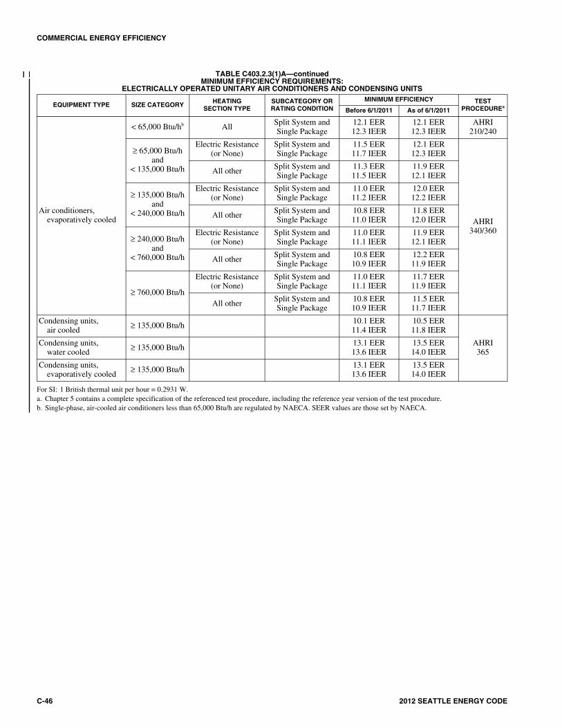
COMMERCIAL ENERGY EFFICIENCY
C-46 2012 SEATTLE ENERGY CODE
TABLE C403.2.3(1)A—continuedMINIMUM EFFICIENCY REQUIREMENTS:
ELECTRICALLY OPERATED UNITARY AIR CONDITIONERS AND CONDENSING UNITS
For SI: 1 British thermal unit per hour = 0.2931 W.a. Chapter 5 contains a complete specification of the referenced test procedure, including the reference year version of the test procedure.b. Single-phase, air-cooled air conditioners less than 65,000 Btu/h are regulated by NAECA. SEER values are those set by NAECA.
EQUIPMENT TYPE SIZE CATEGORY HEATING SECTION TYPE
SUBCATEGORY ORRATING CONDITION
MINIMUM EFFICIENCY TEST PROCEDUREa
Before 6/1/2011 As of 6/1/2011
Air conditioners,evaporatively cooled
< 65,000 Btu/hb All Split System andSingle Package
12.1 EER12.3 IEER
12.1 EER12.3 IEER
AHRI210/240
≥ 65,000 Btu/h and
< 135,000 Btu/h
Electric Resistance(or None)
Split System andSingle Package
11.5 EER11.7 IEER
12.1 EER12.3 IEER
AHRI340/360
All other Split System andSingle Package
11.3 EER11.5 IEER
11.9 EER12.1 IEER
≥ 135,000 Btu/h and
< 240,000 Btu/h
Electric Resistance(or None)
Split System andSingle Package
11.0 EER11.2 IEER
12.0 EER12.2 IEER
All other Split System andSingle Package
10.8 EER11.0 IEER
11.8 EER12.0 IEER
≥ 240,000 Btu/h and
< 760,000 Btu/h
Electric Resistance(or None)
Split System andSingle Package
11.0 EER11.1 IEER
11.9 EER12.1 IEER
All otherSplit System andSingle Package
10.8 EER10.9 IEER
12.2 EER11.9 IEER
≥ 760,000 Btu/h
Electric Resistance(or None)
Split System andSingle Package
11.0 EER11.1 IEER
11.7 EER11.9 IEER
All otherSplit System andSingle Package
10.8 EER10.9 IEER
11.5 EER11.7 IEER
Condensing units,air cooled ≥ 135,000 Btu/h
10.1 EER11.4 IEER
10.5 EER11.8 IEER
AHRI365
Condensing units,water cooled ≥ 135,000 Btu/h
13.1 EER13.6 IEER
13.5 EER14.0 IEER
Condensing units,evaporatively cooled ≥ 135,000 Btu/h
13.1 EER13.6 IEER
13.5 EER14.0 IEER

COMMERCIAL ENERGY EFFICIENCY
2012 SEATTLE ENERGY CODE C-47
TABLE C403.2.3(1)BMINIMUM EFFICIENCY REQUIREMENTS:
AIR CONDITIONERS AND CONDENSING UNITS SERVING COMPUTER ROOMS
a. Net sensible cooling capacity: The total gross cooling capacity less the latent cooling less the energy to the air movement system. (Total Gross—latent—FanPower).
b. Sensible coefficient of performance (SCOP-127): a ratio calculated by dividing the net sensible cooling capacity in watts by the total power input in watts(excluding re-heaters and humidifiers) at conditions defined in ASHRAE Standard 127. The net sensible cooling capacity is the gross sensible capacity minusthe energy dissipated into the cooled space by the fan system.
EQUIPMENT TYPE NET SENSIBLECOOLING CAPACITYa
MINIMUMSCOP-127b EFFICIENCY
DOWNFLOW UNITS/UPFLOW UNITS
TESTPROCEDURE
Air conditioners, air cooled
< 65,000 Btu/h (< 19 kW) 2.20/2.09
ANSI/ASHRAE 127 65,000 Btu/h
and < 240,000 Btu/h( 19kW and < 70 kW)
2.10/1.99
240,000 Btu/h ( 70 kW) 1.90/1.79
Air conditioners, water cooled
< 65,000 Btu/h (< 19 kW) 2.60/2.49
ANSI/ASHRAE 127 65,000 Btu/h
and < 240,000 Btu/h(19kW and < 70 kW)
2.50/2.39
240,000 Btu/h ( 70 kW) 2.40/2.29
Air conditioners, water cooledwith fluid economizer
< 65,000 Btu/h (< 19 kW) 2.55/2.44
ANSI/ASHRAE 127 65,000 Btu/h
and < 240,000 Btu/h(19kW and < 70 kW)
2.45/2.34
240,000 Btu/h ( 70 kW) 2.35/2.24
Air conditioners, glycol cooled(rated at 40% propylene glycol)
< 65,000 Btu/h (< 19 kW) 2.50/2.39
ANSI/ASHRAE 127 65,000 Btu/h
and < 240,000 Btu/h(19kW and < 70 kW)
2.15/2.04
240,000 Btu/h ( 70 kW) 2.10/1.99
Air conditioners, glycol cooled (rated at 40% propylene glycol)with fluid economizer
< 65,000 Btu/h (< 19 kW) 2.45/2.34
ANSI/ASHRAE 127 65,000 Btu/h and
< 240,000 Btu/h(19kW and < 70 kW)
2.10/1.99
240,000 Btu/h ( 70 kW) 2.05/1.94

COMMERCIAL ENERGY EFFICIENCY
C-48 2012 SEATTLE ENERGY CODE
TABLE C403.2.3(1)CMINIMUM EFFICIENCY REQUIREMENTS:
ELECTRICALLY OPERATED VARIABLE REFRIGERANT FLOW AIR CONDITIONERS
For SI: 1 British thermal unit per hour = 0.2931 W.
EQUIPMENT TYPE SIZE CATEGORY HEATINGSECTION TYPE
SUBCATEGORY ORRATING CONDITION MINIMUM EFFICIENCY TEST PROCEDURE
VRF Air Conditioners,Air Cooled
< 65,000 Btu/h All VRF Multi-splitSystem
13.0 SEER
AHRI 1230
65,000 Btu/hand < 135,000 Btu/h
Electric Resistance(or none)
VRF Multi-splitSystem
11.2 EER13.1 IEER
135,000 Btu/hand < 240,000 Btu/h
Electric Resistance(or none)
VRF Multi-splitSystem
11.0 EER12.9 IEER
240,000 Btu/h Electric Resistance(or none)
VRF Multi-splitSystem
10.0 EER11.6 IEER
TABLE C403.2.3(1)DMINIMUM EFFICIENCY REQUIREMENTS:
ELECTRICALLY OPERATED VARIABLE REFRIGERANT FLOW AIR-TO-AIR AND APPLIED HEAT PUMPS
(continued)
EQUIPMENT TYPE SIZE CATEGORY HEATINGSECTION TYPE
SUBCATEGORY ORRATING CONDITION MINIMUM EFFICIENCY TEST PROCEDURE
VRF Air Cooled,(cooling mode)
< 65,000 Btu/h All VRF Multi-splitSystem 13.0 SEER
AHRI 1230
65,000 Btu/hand < 135,000 Btu/h
Electric Resistance(or none)
VRF Multi-splitSystem
11.0 EER12.9 IEER
65,000 Btu/hand < 135,000 Btu/h
Electric Resistance(or none)
VRF Multi-splitSystem with
Heat Recovery
10.8 EER12.7 IEER
135,000 Btu/hand < 240,000 Btu/h
Electric Resistance(or none)
VRF Multi-splitSystem
10.6 EER12.3 IEER
135,000 Btu/hand < 240,000 Btu/h
Electric Resistance(or none)
VRF Multi-splitSystem with
Heat Recovery
10.4 EER12.1 IEER
240,000 Btu/hElectric Resistance
(or none)VRF Multi-split
System9.5 EER
11.0 IEER
240,000 Btu/hElectric Resistance
(or none)
VRF Multi-splitSystem with
Heat Recovery
9.3 EER10.8 IEER
VRF Water source(cooling mode)
< 65,000 Btu/h AllVRF Multi-split
systems86ºF entering water
12.0 EER
AHRI 1230
< 65,000 Btu/h All
VRF Multi-splitsystems with
Heat Recovery86ºF entering water
11.8 EER
65,000 Btu/hand < 135,000 Btu/h
AllVRF Multi-split
System86ºF entering water
12.0 EER
65,000 Btu/hand <135,000 Btu/h
All
VRF Multi-splitSystem with
Heat Recovery86ºF entering water
11.8 EER
135,000 Btu/h AllVRF Multi-split
System86ºF entering water
10.0 EER
135,000 Btu/h All
VRF Multi-splitSystem with
Heat Recovery86ºF entering water
9.8 EER

COMMERCIAL ENERGY EFFICIENCY
2012 SEATTLE ENERGY CODE C-49
TABLE C403.2.3(1)D—continuedMINIMUM EFFICIENCY REQUIREMENTS:
ELECTRICALLY OPERATED VARIABLE REFRIGERANT FLOW AIR-TO-AIR AND APPLIED HEAT PUMPS
For SI: 1 British thermal unit per hour = 0.2931 W, °C = [(°F) - 32]/1.8.
EQUIPMENT TYPE SIZE CATEGORY HEATINGSECTION TYPE
SUBCATEGORY ORRATING CONDITION MINIMUM EFFICIENCY TEST PROCEDURE
VRF Groundwatersource (coolingmode)
< 135,000 Btu/h AllVRF Multi-split
System59ºF entering water
16.2 EER
AHRI 1230
< 135,000 Btu/h All
VRF Multi-splitSystem with
Heat Recovery59ºF entering water
16.0 EER
135,000 Btu/h AllVRF Multi-split
System59ºF entering water
13.8 EER
135,000 Btu/h All
VRF Multi-splitSystem with
Heat Recovery59ºF entering water
13.6 EER
VRFGround source(cooling mode)
< 135,000 Btu/h AllVRF Multi-split
System77ºF entering water
13.4 EER
AHRI 1230
< 135,000 Btu/h All
VRF Multi-splitSystem with Heat
Recovery77ºF entering water
13.2 EER
135,000 Btu/h AllVRF Multi-split
System77ºF entering water
11.0 EER
135,000 Btu/h All
VRF Multi-splitSystem with Heat
Recovery77ºF entering water
10.8 EER
VRFAir Cooled (heating mode)
< 65,000 Btu/h(cooling capacity) —
VRF Multi-splitSystem 7.7 HSPF
AHRI 1230
65,000 Btu/hand < 135,000 Btu/h(cooling capacity)
—VRF Multi-split system
47ºF db/43ºF wb outdoor air17ºF db/15ºF wb outdoor air
3.3 COP2.25 COP
135,000 Btu/h(cooling capacity) —
VRF Multi-split System47ºF db/43ºF wb outdoor air17ºF db/15ºF wb outdoor air
3.2 COP2.05 COP
VRFWater source(heating mode)
< 135,000 Btu/h(cooling capacity) — VRF Multi-split System
68ºF entering water 4.2 COPAHRI 1230
135,000 Btu/h(cooling capacity) —
VRF Multi-split System68ºF entering water 3.9 COP
VRF Groundwatersource (heatingmode)
< 135,000 Btu/h(cooling capacity)
— VRF Multi-split System50ºF entering water
3.6 COPAHRI 1230
135,000 Btu/h(cooling capacity) — VRF Multi-split System
50ºF entering water 3.3 COP
VRFGround source(heating mode)
< 135,000 Btu/h(cooling capacity) —
VRF Multi-split System32ºF entering water 3.1 COP
AHRI 1230 135,000 Btu/h(cooling capacity) —
VRF Multi-split System32ºF entering water 2.8 COP
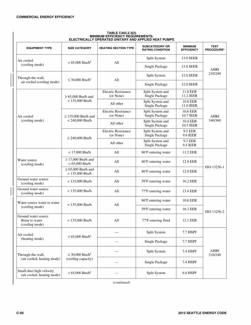
COMMERCIAL ENERGY EFFICIENCY
C-50 2012 SEATTLE ENERGY CODE
TABLE C403.2.3(2)MINIMUM EFFICIENCY REQUIREMENTS:
ELECTRICALLY OPERATED UNITARY AND APPLIED HEAT PUMPS
(continued)
EQUIPMENT TYPE SIZE CATEGORY HEATING SECTION TYPE SUBCATEGORY ORRATING CONDITION
MINIMUMEFFICIENCY
TEST PROCEDUREa
Air cooled(cooling mode) < 65,000 Btu/hb All
Split System 13.0 SEER
AHRI210/240
Single Package 13.0 SEER
Through-the-wall,air cooled (cooling mode)
≤ 30,000 Btu/hb AllSplit System 12.0 SEER
Single Package 12.0 SEER
Air cooled(cooling mode)
≥ 65,000 Btu/h and < 135,000 Btu/h
Electric Resistance(or None)
Split System andSingle Package
11.0 EER11.2 IEER
AHRI340/360
All other Split System andSingle Package
10.8 EER11.0 IEER
≥ 135,000 Btu/h and< 240,000 Btu/h
Electric Resistance(or None)
Split System andSingle Package
10.6 EER10.7 IEER
All other Split System andSingle Package
10.4 EER10.5 IEER
≥ 240,000 Btu/h
Electric Resistance(or None)
Split System andSingle Package
9.5 EER9.6 IEER
All other Split System andSingle Package
9.3 EER9.4 IEER
Water source(cooling mode)
< 17,000 Btu/h All 86oF entering water 11.2 EER
ISO 13256-1
≥ 17,000 Btu/h and < 65,000 Btu/h All 86oF entering water 12.0 EER
≥ 65,000 Btu/h and < 135,000 Btu/h All 86oF entering water 12.0 EER
Ground water source(cooling mode) < 135,000 Btu/h All 59oF entering water 16.2 EER
Ground water source(cooling mode)
< 135,000 Btu/h All 77oF entering water 13.4 EER
Water-source water to water(cooling mode)
< 135,000 Btu/h All86oF entering water 10.6 EER
ISO 13256-259oF entering water 16.3 EER
Ground water sourceBrine to water(cooling mode)
< 135,000 Btu/h All 77oF entering fluid 12.1 EER
Air cooled(heating mode) < 65,000 Btu/hb
— Split System 7.7 HSPF
AHRI210/240
— Single Package 7.7 HSPF
Through-the-wall,(air cooled, heating mode)
≤ 30,000 Btu/hb
(cooling capacity)
— Split System 7.4 HSPF
— Single Package 7.4 HSPF
Small-duct high velocity(air cooled, heating mode)
< 65,000 Btu/hb — Split System 6.8 HSPF
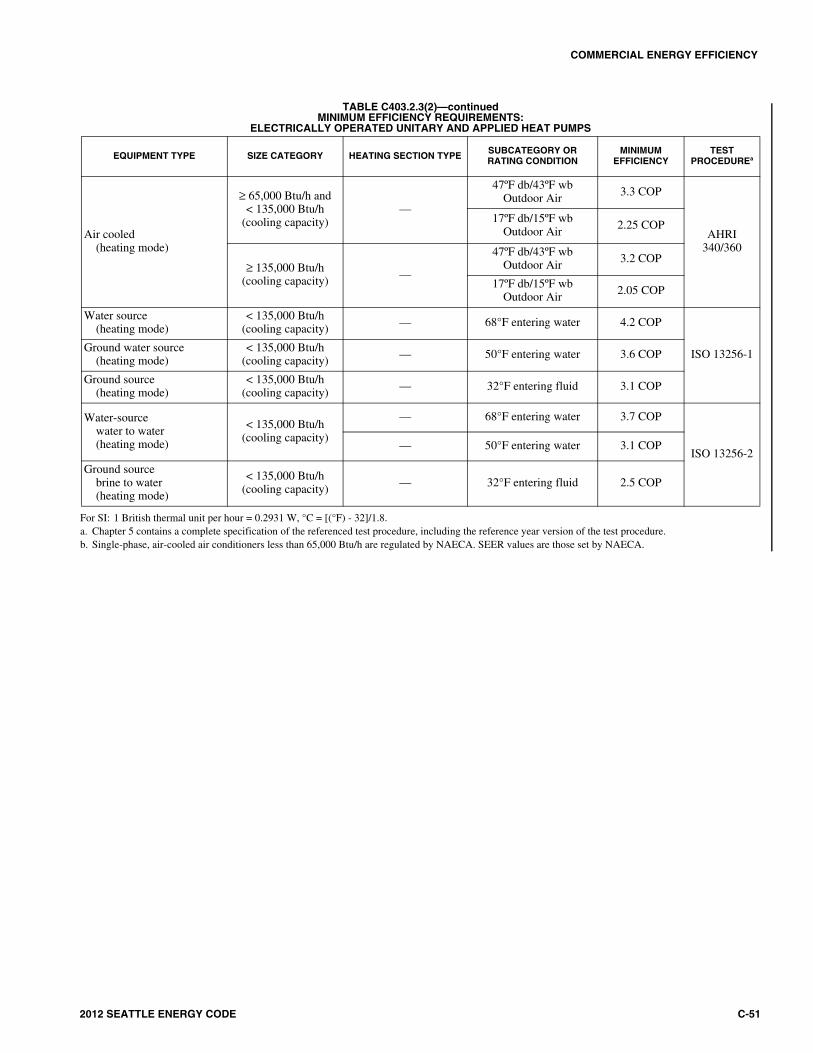
COMMERCIAL ENERGY EFFICIENCY
2012 SEATTLE ENERGY CODE C-51
TABLE C403.2.3(2)—continuedMINIMUM EFFICIENCY REQUIREMENTS:
ELECTRICALLY OPERATED UNITARY AND APPLIED HEAT PUMPS
For SI: 1 British thermal unit per hour = 0.2931 W, °C = [(°F) - 32]/1.8.a. Chapter 5 contains a complete specification of the referenced test procedure, including the reference year version of the test procedure.b. Single-phase, air-cooled air conditioners less than 65,000 Btu/h are regulated by NAECA. SEER values are those set by NAECA.
EQUIPMENT TYPE SIZE CATEGORY HEATING SECTION TYPE SUBCATEGORY ORRATING CONDITION
MINIMUMEFFICIENCY
TEST PROCEDUREa
Air cooled(heating mode)
≥ 65,000 Btu/h and< 135,000 Btu/h
(cooling capacity)—
47ºF db/43ºF wbOutdoor Air 3.3 COP
AHRI340/360
17ºF db/15ºF wbOutdoor Air
2.25 COP
≥ 135,000 Btu/h(cooling capacity) —
47ºF db/43ºF wbOutdoor Air 3.2 COP
17ºF db/15ºF wbOutdoor Air 2.05 COP
Water source(heating mode)
< 135,000 Btu/h(cooling capacity) — 68°F entering water 4.2 COP
ISO 13256-1Ground water source (heating mode)
< 135,000 Btu/h(cooling capacity) — 50°F entering water 3.6 COP
Ground source(heating mode)
< 135,000 Btu/h(cooling capacity) — 32°F entering fluid 3.1 COP
Water-sourcewater to water (heating mode)
< 135,000 Btu/h(cooling capacity)
— 68°F entering water 3.7 COP
ISO 13256-2— 50°F entering water 3.1 COP
Ground source brine to water (heating mode)
< 135,000 Btu/h(cooling capacity) — 32°F entering fluid 2.5 COP

COMMERCIAL ENERGY EFFICIENCY
C-52 2012 SEATTLE ENERGY CODE
TABLE C403.2.3(3)MINIMUM EFFICIENCY REQUIREMENTS:
ELECTRICALLY OPERATED PACKAGED TERMINAL AIR CONDITIONERS, PACKAGED TERMINAL HEAT PUMPS, SINGLE-PACKAGE VERTICAL AIR CONDITIONERS,
SINGLE-PACKAGE VERTICAL HEAT PUMPS, ROOM AIR CONDITIONERS AND ROOM AIR-CONDITIONER HEAT PUMPS
(continued)
EQUIPMENT TYPE SIZE CATEGORY (INPUT)
SUBCATEGORY OR RATING CONDITION
MINIMUM EFFICIENCY TEST PROCEDUREa
Before 10/08/2012 As of 10/08/2012
PTAC (cooling mode)new construction
All Capacities 95°F db outdoor air 12.5 - (0.213 × Cap/1000) EER
13.8 - (0.300 × Cap/1000) EER
AHRI310/380
PTAC (cooling mode)replacementsb All Capacities 95°F db outdoor air
10.9 - (0.213 × Cap/1000) EER
10.9 - (0.213 × Cap/1000) EER
PTHP (cooling mode)new construction All Capacities 95°F db outdoor air
12.3 - (0.213 × Cap/1000) EER
14.0 - (0.300 × Cap/1000) EER
PTHP (cooling mode)replacementsb All Capacities 95°F db outdoor air
10.8 - (0.213 × Cap/1000) EER
10.8 - (0.213 × Cap/1000) EER
PTHP (heating mode)new construction All Capacities —
3.2 - (0.026 × Cap/1000) COP
3.7 - (0.052 × Cap/1000) COP
PTHP (heating mode)replacementsb All Capacities —
2.9 - (0.026 × Cap/1000) COP
2.9 - (0.026 × Cap/1000) COP
SPVAC(cooling mode)
< 65,000 Btu/h95°F db/ 75°F wb
outdoor air 9.0 EER 9.0 EER
AHRI 390
≥ 65,000 Btu/h and < 135,000 Btu/h
95°F db/ 75°F wb outdoor air 8.9 EER 8.9 EER
≥ 135,000 Btu/h and < 240,000 Btu/h
95°F db/ 75°F wb outdoor air 8.6 EER 8.6 EER
SPVHP(cooling mode)
< 65,000 Btu/h95°F db/ 75°F wb
outdoor air 9.0 EER 9.0 EER
≥ 65,000 Btu/h and < 135,000 Btu/h
95°F db/ 75°F wb outdoor air 8.9 EER 8.9 EER
≥ 135,000 Btu/h and < 240,000 Btu/h
95°F db/ 75°F wb outdoor air 8.6 EER 8.6 EER
SPVHP(heating mode)
<65,000 Btu/h47°F db/ 43°F wb
outdoor air 3.0 COP 3.0 COP
AHRI 390≥ 65,000 Btu/h and
< 135,000 Btu/h47°F db/ 43°F wb
outdoor air 3.0 COP 3.0 COP
≥ 135,000 Btu/h and < 240,000 Btu/h
47°F db/ 43°F wb outdoor air 2.9 COP 2.9 COP

COMMERCIAL ENERGY EFFICIENCY
2012 SEATTLE ENERGY CODE C-53
TABLE C403.2.3(3)—continuedMINIMUM EFFICIENCY REQUIREMENTS:
ELECTRICALLY OPERATED PACKAGED TERMINAL AIR CONDITIONERS, PACKAGED TERMINAL HEAT PUMPS, SINGLE-PACKAGE VERTICAL AIR CONDITIONERS,
SINGLE VERTICAL HEAT PUMPS, ROOM AIR CONDITIONERS AND ROOM AIR-CONDITIONER HEAT PUMPS
For SI: 1 British thermal unit per hour = 0.2931 W, °C = [(°F) - 32]/1.8.“Cap” = The rated cooling capacity of the product in Btu/h. If the unit’s capacity is less than 7000 Btu/h, use 7000 Btu/h in the calculation. If the unit’s capacity
is greater than 15,000 Btu/h, use 15,000 Btu/h in the calculations.a. Chapter 5 of the referenced standard contains a complete specification of the referenced test procedure, including the referenced year version of the test
procedure.b. Replacement unit shall be factory labeled as follows: “MANUFACTURED FOR NONSTANDARD SIZE APPLICATIONS ONLY: NOT TO BE
INSTALLED IN NEW STANDARD PROJECTS” or “MANUFACTURED FOR REPLACEMENT APPLICATIONS ONLY: NOT TO BE INSTALLEDIN NEW CONSTRUCTION PROJECTS.” Replacement efficiencies apply only to units with existing sleeves less than 16 inches (406 mm) in height and lessthan 42 inches (1067 mm) in width.
EQUIPMENT TYPE SIZE CATEGORY (INPUT)
SUBCATEGORY OR RATING CONDITION
MINIMUM EFFICIENCY TEST PROCEDUREa
Before 10/08/2012 As of 10/08/2012
Room air conditioners,with louvered sides
< 6,000 Btu/h — 9.7 SEER 9.7 SEER
ANSI/AHAMRAC-1
≥ 6,000 Btu/h and < 8,000 Btu/h
— 9.7 EER 9.7 EER
≥ 8,000 Btu/h and < 14,000 Btu/h
— 9.8 EER 9.8 EER
≥ 14,000 Btu/h and < 20,000 Btu/h
— 9.7 SEER 9.7 SEER
≥ 20,000 Btu/h — 8.5 EER 8.5 EER
Room air conditioners,without louveredsides
< 8,000 Btu/h — 9.0 EER 9.0 EER
≥ 8,000 Btu/h and < 20,000 Btu/h — 8.5 EER 8.5 EER
≥ 20,000 Btu/h — 8.5 EER 8.5 EER
Room air-conditionerheat pumps with louvered sides
< 20,000 Btu/h — 9.0 EER 9.0 EER
≥ 20,000 Btu/h — 8.5 EER 8.5 EER
Room air-conditionerheat pumps withoutlouvered sides
< 14,000 Btu/h — 8.5 EER 8.5 EER
≥ 14,000 Btu/h — 8.0 EER 8.0 EER
Room air conditionercasement only All capacities — 8.7 EER 8.7 EER
Room air conditionercasement-slider All capacities — 9.5 EER 9.5 EER

COMMERCIAL ENERGY EFFICIENCY
C-54 2012 SEATTLE ENERGY CODE
TABLE 403.2.3(4) WARM AIR FURNACES AND COMBINATION WARM AIR FURNACES/AIR-CONDITIONING UNITS,
WARM AIR DUCT FURNACES AND UNIT HEATERS, MINIMUM EFFICIENCY REQUIREMENTS
For SI: 1 British thermal unit per hour = 0.2931 W.a. Chapter 5 contains a complete specification of the referenced test procedure, including the referenced year version of the test procedure.b. Minimum and maximum ratings as provided for and allowed by the unit’s controls.c. Combination units not covered by the National Appliance Energy Conservation Act of 1987 (NAECA) (3-phase power or cooling capacity greater than or
equal to 65,000 Btu/h [19 kW]) shall comply with either rating.d. Et = Thermal efficiency. See test procedure for detailed discussion.e. Ec = Combustion efficiency (100% less flue losses). See test procedure for detailed discussion.f. Ec = Combustion efficiency. Units must also include an IID, have jackets not exceeding 0.75 percent of the input rating, and have either power venting or a
flue damper. A vent damper is an acceptable alternative to a flue damper for those furnaces where combustion air is drawn from the conditioned space.g. Et = Thermal efficiency. Units must also include an IID, have jacket losses not exceeding 0.75 percent of the input rating, and have either power venting or a
flue damper. A vent damper is an acceptable alternative to a flue damper for those furnaces where combustion air is drawn from the conditioned space.
EQUIPMENT TYPE SIZE CATEGORY(INPUT)
SUBCATEGORY ORRATING CONDITION
MINIMUMEFFICIENCYd, e TEST PROCEDUREa
Warm air furnaces,gas fired
< 225,000 Btu/h —78% AFUE or
80%Etc
DOE 10 CFR Part 430or ANSI Z21.47
≥ 225,000 Btu/h Maximum capacityc 80%Etf ANSI Z21.47
Warm air furnaces,oil fired
< 225,000 Btu/h — 78% AFUE or80%Et
c DOE 10 CFR Part 430
or UL 727
≥ 225,000 Btu/h Maximum capacityb 81%Etg UL 727
Warm air duct furnaces,gas fired
All capacities Maximum capacityb 80%Ec ANSI Z83.8
Warm air unit heaters,gas fired
All capacities Maximum capacityb 80%Ec ANSI Z83.8
Warm air unit heaters,oil fired
All capacities Maximum capacityb 80%Ec UL 731

COMMERCIAL ENERGY EFFICIENCY
2012 SEATTLE ENERGY CODE C-55
TABLE C403.2.3(6)RESERVED
>
TABLE C403.2.3(5)MINIMUM EFFICIENCY REQUIREMENTS: GAS- AND OIL-FIRED BOILERS
For SI: 1 British thermal unit per hour = 0.2931 W.Ec = Combustion efficiency (100 percent less flue losses). Et = Thermal efficiency. See referenced standard document for detailed information.a. These requirements apply to boilers with rated input of 8,000,000 Btu/h or less that are not packaged boilers and to all packaged boilers. Minimum efficiency
requirements for boilers cover all capacities of packaged boilers.b. Maximum capacity – minimum and maximum ratings as provided for and allowed by the unit’s controls.c. Includes oil-fired (residual).
EQUIPMENT TYPEa SUBCATEGORY OR RATING CONDITION SIZE CATEGORY (INPUT) MINIMUM EFFICIENCY TEST PROCEDURE
Boilers, hot water
Gas-fired
< 300,000 Btu/h 80% AFUE 10 CFR Part 430
≥ 300,000 Btu/h and ≤ 2,500,000 Btu/hb 80% Et 10 CFR Part 431> 2,500,000 Btu/ha 82% Ec
Oil-firedc
< 300,000 Btu/h 80% AFUE 10 CFR Part 430
≥ 300,000 Btu/h and ≤ 2,500,000 Btu/hb 82% Et 10 CFR Part 431> 2,500,000 Btu/ha 84% Ec
Boilers, steam
Gas-fired < 300,000 Btu/h 75% AFUE 10 CFR Part 430
Gas-fired- all, except natural draft≥ 300,000 Btu/h and ≤ 2,500,000 Btu/hb 79% Et
10 CFR Part 431> 2,500,000 Btu/ha 79% Et
Gas-fired-natural draft≥ 300,000 Btu/h and ≤ 2,500,000 Btu/hb 77% Et
> 2,500,000 Btu/ha 77% Et
Oil-firedc
< 300,000 Btu/h 80% AFUE 10 CFR Part 430
≥ 300,000 Btu/h and ≤ 2,500,000 Btu/hb 81% Et 10 CFR Part 431> 2,500,000 Btu/ha 81% Et

COMMERCIAL ENERGY EFFICIENCY
C-56 2012 SEATTLE ENERGY CODE
TABLE C403.2.3(7)MINIMUM EFFICIENCY REQUIREMENTS:
WATER CHILLING PACKAGESa
For SI: 1 ton = 3517 W, 1 British thermal unit per hour = 0.2931 W, °C = [(°F) - 32]/1.8.NA = Not applicable, not to be used for compliance; NR = No requirement.a. The centrifugal chiller equipment requirements, after adjustment in accordance with Section C403.2.3.1 or Section C403.2.3.2, do not apply to chillers used
in low-temperature applications where the design leaving fluid temperature is less than 36ºF. The requirements do not apply to positive displacement chillerswith leaving fluid temperatures less than or equal to 32ºF. The requirements do not apply to absorption chillers with design leaving fluid temperatures less than40ºF.
b. Compliance with this standard can be obtained by meeting the minimum requirements of Path A or B. However, both the full load and IPLV shall be met to fulfillthe requirements of Path A or B.
c. Chapter 5 contains a complete specification of the referenced test procedure, including the referenced year version of the test procedure.
EQUIPMENT TYPESIZE
CATEGORY UNITS
BEFORE 1/1/2010 AS OF 1/1/2010b
TESTPROCEDUREc
FULLLOAD IPLV
PATH A PATH B
FULL LOAD IPLV
FULLLOAD IPLV
Air-cooled chillers< 150 tons EER
≥ 9.562 ≥ 10.416≥ 9.562 ≥ 12.500 NA NA
AHRI550/590
≥ 150 tons EER ≥ 9.562 ≥ 12.750 NA NA
Air cooled without condenser, electricaloperated
Allcapacities EER ≥ 10.586 ≥ 11.782
Air-cooled chillers without condensers shall be rated with matching condensers and comply with the air-cooled chiller efficiency requirements
Water cooled, electrically operated,reciprocating
Allcapacities
kW/ton ≤ 0.837 ≤ 0.696Reciprocating units shall comply with water cooled positive displacement effi-ciency requirements
Water cooled, electrically operated, positive displacement
< 75 tons kW/ton
≤ 0.790 ≤ 0.676
≤ 0.780 ≤ 0.630 ≤ 0.800 ≤ 0.600
≥ 75 tonsand
< 150 tonskW/ton ≤ 0.775 ≤ 0.615 ≤ 0.790 ≤ 0.586
≥ 150 tonsand
< 300 tonskW/ton ≤ 0.717 ≤ 0.627 ≤ 0.680 ≤ 0.580 ≤ 0.718 ≤ 0.540
≥ 300 tons kW/ton ≤ 0.639 ≤ 0.571 ≤ 0.620 ≤ 0.540 ≤ 0.639 ≤ 0.490
Water cooled, electrically operated,centrifugal
< 150 tons kW/ton ≤ 0.703 ≤ 0.669
≤ 0.634 ≤ 0.596 ≤ 0.639 ≤ 0.450≥ 150 tonsand
< 300 tonskW/ton ≤ 0.634 ≤ 0.596
≥ 300 tonsand
< 600 tonskW/ton ≤ 0.576 ≤ 0.549 ≤ 0.576 ≤ 0.549 ≤ 0.600 ≤ 0.400
≥ 600 tons kW/ton ≤ 0.576 ≤ 0.549 ≤ 0.570 ≤ 0.539 ≤ 0.590 ≤ 0.400
Air cooled, absorption single effect Allcapacities COP ≥ 0.600 NR ≥ 0.600 NR NA NA
AHRI 560Water cooled, absorption single effect All
capacitiesCOP ≥ 0.700 NR ≥ 0.700 NR NA NA
Absorption double effect, indirect firedAll
capacities COP ≥ 1.000 ≥ 1.050 ≥ 1.000 ≥ 1.050 NA NA
Absorption double effect, direct fired Allcapacities COP ≥ 1.000 ≥ 1.000 ≥ 1.000 ≥ 1.000 NA NA

COMMERCIAL ENERGY EFFICIENCY
2012 SEATTLE ENERGY CODE C-57
C403.2.4.4 Shutoff damper controls. ((Both o)) Outdoorair supply, relief and exhaust ducts shall be equippedwith motorized dampers complying with SectionC402.4.5.2 that will automatically shut when the sys-tems or spaces served are not in use or during buildingwarm-up, cooldown, and setback.
Exceptions:
1. Gravity relief dampers complying with excep-tion 1 to Section C402.4.5.2 serving systemswith a design outdoor air intake, relief or
exhaust capacity of less than ((5,000)) 300cfm (((2360)) 141 L/s) total supply shall bepermitted ((in buildings less than three storiesin height)).
2. Gravity dampers shall be permitted for buildingsof any height located in Climate Zones 1, 2 and 3.
3. Gravity (nonmotorized) dampers in Group Roccupancies where the design outdoor airintake or exhaust capacity does not exceed((400)) 300 cfm (((189)) 141 L/s).
TABLE C403.2.3(8)MINIMUM EFFICIENCY REQUIREMENTS:
HEAT REJECTION EQUIPMENT
For SI: °C = [(°F)-32]/1.8, L/s · kW = (gpm/hp)/(11.83), COP = (Btu/h · hp)/(2550.7).db = dry bulb temperature, °F, wb = wet bulb temperature, °F.a. The efficiencies and test procedures for both open and closed circuit cooling towers are not applicable to hybrid cooling towers that contain a combination of
wet and dry heat exchange sections.b. For purposes of this table, open circuit cooling tower performance is defined as the water flow rating of the tower at the thermal rating condition listed in
Table 403.2.3(8) divided by the fan nameplate rated motor power.c. For purposes of this table, closed circuit cooling tower performance is defined as the water flow rating of the tower at the thermal rating condition listed in
Table 403.2.3(8) divided by the sum of the fan nameplate rated motor power and the spray pump nameplate rated motor power.d. For purposes of this table, air-cooled condenser performance is defined as the heat rejected from the refrigerant divided by the fan nameplate rated motor
power.e. Chapter 5 contains a complete specification of the referenced test procedure, including the referenced year version of the test procedure.f. If a certification program exists for a covered product, and it includes provisions for verification and challenge of equipment efficiency ratings, then the
product shall be listed in the certification program, or, if a certification program exists for a covered product, and it includes provisions for verification andchallenge of equipment efficiency ratings, but the product is not listed in the existing certification program, the ratings shall be verified by an independentlaboratory test report.
EQUIPMENT TYPEaTOTAL SYSTEM HEAT
REJECTION CAPACITY AT RATED CONDITIONS
SUBCATEGORY OR RATING CONDITION PERFORMANCE REQUIREDb, c, d TEST PROCEDUREe, f
Propeller or axial fan open circuit cooling towers
All 95°F Entering Water85°F Leaving Water
75°F Entering wb≥ 38.2 gpm/hp CTI ATC-105 and
CTI STD-201
Centrifugal fan open circuit cooling towers All
95°F Entering Water85°F Leaving Water
75°F Entering wb≥ 20.0 gpm/hp
CTI ATC-105 and CTI STD-201
Propeller or axial fan closed circuit cooling towers All
102°F Entering Water90°F Leaving Water
75°F Entering wb≥ 14.0 gpm/hp CTI ATC-105S and
CTI STD-201
Centrifugal closed circuit cooling towers All
102°F Entering Water90°F Leaving Water
75°F Entering wb≥ 7.0 gpm/hp
CTI ATC-105S and CTI STD-201
Air-cooled condensers All
125°F Condensing Temperature R-22 Test Fluid
190°F Entering Gas Temperature 15°F Subcooling 95°F Entering db
≥ 176,000 Btu/h·hp AHRI 460
TABLE C403.2.3(9)HEAT TRANSFER EQUIPMENT
NR = No Requirementa. Chapter 5 contains a complete specification of the referenced test procedure, including the referenced year version of the test procedure.
EQUIPMENT TYPE SUBCATEGORY MINIMUM EFFICIENCY TEST PROCEDUREa
Liquid-to-liquid heat exchangers Plate type NR AHRI 400

COMMERCIAL ENERGY EFFICIENCY
C-58 2012 SEATTLE ENERGY CODE
4. Systems serving areas which require continu-ous operation.
5. Combustion air intakes.
6. Operation of dampers shall be allowed duringventilation prepurge one hour before expectedoccupancy and for unoccupied period precool-ing during the cooling season.
7. Dampers are not required in systems wherespecifically prohibited by the InternationalMechanical Code.
C403.2.4.5 Snow melt system controls. Snow- and ice-melting systems, supplied through energy service to thebuilding, shall include automatic controls capable of shut-ting off the system when the pavement temperature isabove 50°F (10°C) and no precipitation is falling and anautomatic or manual control that will allow shutoff whenthe outdoor temperature is above 40°F (4°C) so that thepotential for snow or ice accumulation is negligible.
C403.2.4.6 Combustion heating equipment controls.Combustion heating equipment with a capacity over225,000 Btu/h shall have modulating or staged com-bustion control.
Exceptions:
1. Boilers.
2. Radiant heaters.
C403.2.4.7 Group R-1 hotel/motel guestrooms. Forhotel and motel guestrooms, a minimum of one of thefollowing control technologies shall be required inhotels/motels with over 50 guestrooms such that thespace temperature would automatically setback (win-ter) or set up (summer) by no less than 5°F (3°C) ((orhotel and motel guestrooms, a minimum of)) when theoccupant is not in the room:
1. Controls that are activated by the room occupantvia the primary room access method—Key, card,deadbolt, etc.
2. Occupancy sensor controls that are activated bythe occupant's presence in the room.
C403.2.4.8 Group R-2 and R-3 dwelling units. Theprimary space conditioning system within each dwell-ing unit shall be provided with at least one programma-ble thermostat for the regulation of space temperature.The thermostat shall allow for, at a minimum, a 5-2programmable schedule (weekdays/weekends) and becapable of providing at least two programmable set-back periods per day.
Each additional system provided within the dwellingunit shall be provided with at least one adjustable ther-mostat for the regulation of temperature.
Exceptions:
1. Systems controlled by an occupant sensor that iscapable of shutting the system off when no occu-pant is sensed for a period of up to 30 minutes.
2. Systems controlled solely by a manually oper-ated timer capable of operating the system forno more than two hours.
3. Ductless heat pumps.
Each thermostat shall be capable of being set byadjustment or selection of sensors as follows: Whenused to control heating only: 55°F to 75°F (13°C to24°C); when used to control cooling only: 70°F to 85°F(21°C to 29°C); all other: 55°F to 85°F (13°C to 29°C)with an adjustable deadband of not less than10°F (5°C).
C403.2.4.9 Group R-2 sleeping units. The primaryspace conditioning system within each sleeping unitshall be provided with at least one programmable ther-mostat for the regulation of space temperature. Thethermostat shall allow for, at a minimum, a 5-2 pro-grammable schedule (weekdays/weekends) and becapable of providing at least two programmable set-back periods per day.
Each additional system provided within the sleepingunit shall be provided with at least one adjustable ther-mostat for the regulation of temperature.
Exceptions:
1. Systems controlled by an occupant sensor that iscapable of shutting the system off when nooccupant is sensed for a period of up to 30 min-utes.
2. Systems controlled solely by a manually oper-ated timer capable of operating the system forno more than two hours.
3. Zones with a full HVAC load demand notexceeding 3,400 Btu/h (1 kW) and having areadily accessible manual shutoff switch.
4. Ductless heat pumps.
Each thermostat shall be capable of being set byadjustment or selection of sensors as follows: When usedto control heating only: 55°F to 75°F (13°C to 24°C);when used to control cooling only: 70°F to 85°F (21°Cto 29°C); all other: 55°F to 85°F (13°C to 29°C) with anadjustable deadband of not less than 10°F (5°C).
C403.2.4.10 Direct digital control system capabili-ties. All complex systems equipped with direct digitalcontrol (DDC) systems and all buildings with totalcooling capacity exceeding 780,000 Btu/h (2,662 kW)shall have the following capability:
1. Trending: All control system input and outputpoints shall be accessible and programmed fortrending, and a graphic trending package shall beprovided with the control system.
2. Demand Response Setpoint Adjustment: Controllogic shall increase the cooling zone set points byat least 2°F (1°C) and reduce the heating zone setpoints by at least 2°F (1°C) when activated by ademand response signal. The demand responsesignal shall be a binary input to the control systemor other interface approved by the serving electricutility.
COMMERCIAL ENERGY EFFICIENCY
2012 SEATTLE ENERGY CODE C-59
C403.2.5 Ventilation. Ventilation, either natural or mechani-cal, shall be provided in accordance with Chapter 4 of theInternational Mechanical Code. Where mechanical venti-lation is provided, the system shall provide the capability toreduce the outdoor air supply to the minimum required byChapter 4 of the International Mechanical Code.
C403.2.5.1 Demand controlled ventilation. Demandcontrol ventilation (DCV) shall be provided for spaceslarger than 500 square feet (50 m2) and with an occupantload greater than 25 people per 1000 square feet (93 m2)of floor area (as established in Table 403.3 of the Inter-national Mechanical Code) and served by systems withone or more of the following:
1. An air-side economizer;
2. Automatic modulating control of the outdoor airdamper; or
3. A design outdoor airflow greater than 3,000 cfm(1400 L/s).
Exception: Demand control ventilation is notrequired for systems and spaces as follows:
1. Systems with energy recovery complying withSection C403.2.6.
2. Multiple-zone systems without direct digitalcontrol of individual zones communicatingwith a central control panel.
3. System with a design outdoor airflow less than1,000 cfm (472 L/s).
4. Spaces where the supply airflow rate minusany makeup or outgoing transfer air require-ment is less than 1,200 cfm (600 L/s).
5. Ventilation provided for process loads only.
C403.2.5.2 Occupancy sensors. Classrooms, gyms,auditoriums and conference rooms larger than 500square feet (50 m2) of floor area shall have occupancysensor control that will either close outside air dampersor turn off serving equipment when the space is unoc-cupied except where equipped with another means toautomatically reduce outside air intake below designrates when spaces are partially occupied.
C403.2.5.3 Enclosed loading dock, motor vehiclerepair garage and parking garage exhaust ventila-tion system control. Mechanical ventilation systemsfor enclosed loading docks, motor vehicle repairgarages and parking garages shall be designed toexhaust the airflow rates (maximum and minimum)determined in accordance with the InternationalMechanical Code.
Ventilation systems shall be equipped with a controldevice that operates the system automatically upondetection of vehicle operation or the presence of occu-pants by approved automatic detection devices. Each ofthe following types of controllers shall be capable ofshutting off fans or modulating fan speed. Controldevices shall not reduce airflow rates below the mini-
mum requirement in accordance with the InternationalMechanical Code during scheduled periods of occupiedoperation.
1. Gas sensor controllers used to activate the exhaustventilation system shall stage or modulate fanspeed upon detection of specified gas levels. Allequipment used in sensor controlled systems shallbe designed for the specific use and installed inaccordance with the manufacturer's recommenda-tions. The system shall be arranged to operateautomatically by means of carbon monoxidedetectors applied in conjunction with nitrogendioxide detectors. Garages, repair garages andloading docks shall be equipped with a controllerand a full array of carbon monoxide (CO) sensorsset to maintain levels of carbon monoxide below35 parts per million (ppm). Additionally, a fullarray of nitrogen dioxide detectors shall be con-nected to the controller set to maintain the nitrogendioxide level below the OSHA standard for eighthour exposure. Spacing and location of the sensorsshall be installed in accordance with manufacturerrecommendations.
2. Occupant detection sensors used to activate thesystem shall detect entry ((into the parkinggarage)) along both the vehicle and pedestrianpathways.
C403.2.5.3.1 System activation devices forenclosed loading docks. Ventilation systems forenclosed loading docks shall operate continuouslyduring unoccupied hours at the minimum ventila-tion rate required by Section 404.2 of the Interna-tional Mechanical Code and shall be activated tothe full required ventilation rate by one of the fol-lowing:
1. Gas sensors installed in accordance with theInternational Mechanical Code; or
2. Occupant detection sensors used to activate thesystem that detects entry into the loading areaalong both the vehicle and pedestrian pathways.
C403.2.5.3.2 System activation devices forenclosed parking garages. Ventilation systems forenclosed parking garages shall be activated by gassensors.
Exception: A parking garage ventilation systemhaving a total design capacity under 8,000 cfm(3775 L/s) may use occupant sensors to activatethe full required ventilation rate.
C403.2.5.4 Exhaust systems.
C403.2.5.4.1 Kitchen hoods. Each kitchen areawith total exhaust capacity larger than 2,000 cfm(944 L/s) shall be provided with makeup air sized sothat at least 50 percent of exhaust air volume be (a)unheated or heated to no more than 60°F (16°C) and

COMMERCIAL ENERGY EFFICIENCY
C-60 2012 SEATTLE ENERGY CODE
(b) uncooled or cooled without the use of mechani-cal cooling.
Exceptions:
1. Where hoods are used to exhaust ventila-tion air which would otherwise exfiltrate orbe exhausted by other fan systems. Adetailed accounting of exhaust airflows thataccounts for the impact of any requireddemand controlled ventilation shall be pro-vided on the plans.
2. Certified grease extractor hoods that requirea face velocity no greater than 60 fpm (18.3m/s).
C403.2.5.4.2 Laboratory exhaust systems. Build-ings with laboratory exhaust systems having a totalexhaust rate greater than 5,000 cfm (2,360 L/s) shallinclude heat recovery systems to precondition((ed))makeup air from laboratory exhaust. The heat recov-ery system shall be capable of increasing the outsideair supply temperature at design heating conditionsby 25°F (13.9°C) in Climate Zones 4C/5B and 35°F(19.4°C) in Climate Zone 6B. A provision shall bemade to bypass or control the heat recovery systemto permit air economizer operation as required bySection C403.4.
Exceptions:
1. Variable air volume laboratory exhaust androom supply systems capable of reducingexhaust and makeup air volume to 50 per-cent or less of design values; or
2. Direct makeup (auxiliary) air supply equalto at least 75 percent of the exhaust rate,heated no warmer than 2°F (1.1°C) belowroom set point, cooled to no cooler than3°F (1.7°C) above room set point, nohumidification added, and no simultaneousheating and cooling used for dehumidifica-tion control; or
3. Combined Energy Reduction Method: VAVexhaust and room supply system capable ofreducing exhaust and makeup air volumesand a heat recovery system to preconditionmakeup air from laboratory exhaust thatwhen combined will produce the sameenergy reduction as achieved by a heatrecovery system with a 50 percent sensiblerecovery effectiveness as required above.For calculation purposes, the heat recoverycomponent can be assumed to include themaximum design supply airflow rate atdesign conditions. The combined energyreduction (QER) shall meet the following:
QER QMIN
QMIN = CFMS · (TR · TO) · 1.1 · 0.6
QER = CFMS · (TR · TO) · 1.1(A+B)/100
where:
QMIN = Energy recovery at 60% sensi-ble effectiveness (Btu/h).
QER = Combined energy reduction(Btu/h).
CFMS = The maximum design supplyairflow rate to conditionedspaces served by the system incubic feet per minute.
TR = Space return air dry bulb at winter design conditions.
TO = Outdoor air dry bulb at winterdesign conditions.
A = Percentage that the exhaust andmakeup air volumes can bereduced from design conditions.
B = Percentage sensible heat recovery effectiveness.
C403.2.6 Energy recovery.
C403.2.6.1 Energy recovery ventilation systems.Any system with minimum outside air requirements atdesign conditions greater than 5,000 cfm (2360 L/s) orany system required by Table C403.2.6 shall include anenergy recovery system. The energy recovery systemshall have the capability to provide a change in theenthalpy of the outdoor air supply of not less than 50percent of the difference between the outdoor air andreturn air enthalpies, at design conditions. Where an aireconomizer is required, the energy recovery systemshall include a bypass or controls which permit opera-tion of the economizer as required by Section C403.4.Where a single room or space is supplied by multipleunits, the aggregate ventilation (cfm) of those unitsshall be used in applying this requirement. The return/exhaust air stream temperature for heat recovery deviceselection shall be 70°F (21°C).
Exception: An energy recovery ventilation systemshall not be required in any of the following condi-tions:
1. Where energy recovery systems are pro-hibited by the International MechanicalCode.
2. Laboratory fume hood systems that includeat least one of the following features, andalso comply with Section 403.2.5.4.2:
Informative Note: In Seattle, the outdoor design airtemperature is 24°F as specified in Appendix C. Thedifference between 24°F and 65°F is 41 degrees. One-halfof 41 degrees is 20.5 degrees. Therefore, to provide 50percent heat recovery effectiveness in Seattle, the heatrecovery system shall raise the outside supply airtemperature to a minimum of 44.5°F (24°F + 20.5°F) at theoutdoor design conditions.
COMMERCIAL ENERGY EFFICIENCY
2012 SEATTLE ENERGY CODE C-61
2.1. Variable-air-volume hood exhaust androom supply systems capable ofreducing exhaust and makeup airvolume to 50 percent or less of designvalues.
2.2. Direct makeup (auxiliary) air supplyequal to at least 75 percent of theexhaust rate, heated no warmer than 2°F(1.1°C) above room setpoint, cooled tono cooler than 3°F (1.7°C) below roomsetpoint, no humidification added, andno simultaneous heating and coolingused for dehumidification control.
3. Systems serving spaces that are heated toless than 60°F (15.5°C) and are not cooled.
4. Where more than 60 percent of the outdoorheating energy is provided from site-recov-ered or site solar energy.
5. Heating energy recovery in Climate Zones1 and 2.
6. Cooling energy recovery in Climate Zones3C, 4C, 5B, 5C, 6B, 7 and 8.
7. Systems requiring dehumidification thatemploy energy recovery in series with thecooling coil.
8. Multi-zone systems with cold deck supplyair and zone reheat where the minimumoutdoor air is less than 70 percent of totalsupply air.
9. Systems serving residential multifamilyspaces where the largest source of airexhausted at a single location at the build-ing exterior is less than 25 percent of thedesign outdoor air flow rate.
10. Type I kitchen exhaust hoods.
C403.2.6.2 Condensate systems. On-site steam heat-ing systems shall have condensate water heat recovery.On-site includes a system that is located within or adja-cent to one or more buildings within the boundary of acontiguous area or campus under one ownership andwhich serves one or more of those buildings.
Buildings using steam generated off-site with steamheating systems which do not have condensate waterrecovery shall have condensate water heat recovery.
C403.2.6.3 Condenser heat recovery. Facilities hav-ing food service, meat or deli departments and having500,000 Btu/h (146 kw) or greater of remote refrigera-tion condensers shall have condenser waste heat recov-ery from freezers and coolers and shall use the wasteheat for service water heating, space heating or fordehumidification reheat. Facilities having a gross con-ditioned floor area of 40,000 square feet (3716 m2) orgreater and 1,000,000 Btu/h (293 kw) or greater ofremote refrigeration shall have condenser waste heatrecovery from freezers and coolers and shall use thewaste heat for service water heating, and either forspace heating or for dehumidification reheat for main-taining low space humidity. The required heat recoverysystem shall have the capacity to provide the smallerof:
1. 60 percent of the peak heat rejection load atdesign conditions; or
2. 50 percent of the sum of the service water heatingload plus space heating load.
C403.2.7 Duct and plenum insulation and sealing.
C403.2.7.1 Ducts, shafts and plenums conveying out-side air from the exterior of the building to the mechan-ical system shall meet all air leakage and buildingenvelope insulation requirements of Section C402, plusbuilding envelope vapor control requirements from theInternational Building Code, extending continuouslyfrom the building exterior to an automatic shutoff
TABLE C403.2.6ENERGY RECOVERY REQUIREMENT
NR = not required
CLIMATE ZONE
PERCENT (%) OUTDOOR AIR AT FULL DESIGN AIRFLOW RATE
≥ 30% and < 40% ≥ 40% and < 50% ≥ 50% and < 60% ≥ 60% and < 70% ≥ 70% and < 80% ≥ 80%
DESIGN SUPPLY FAN AIRFLOW RATE (cfm)
3B, 3C, 4B, 4C, 5B NR NR NR NR ≥ 5000 ≥ 5000
1B, 2B, 5C NR NR ≥ 26000 ≥ 12000 ≥ 5000 ≥ 4000
6B ≥ 11000 ≥ 5500 ≥ 4500 ≥ 3500 ≥ 2500 ≥ 1500
1A, 2A, 3A, 4A, 5A, 6A ≥ 5500 ≥ 4500 ≥ 3500 ≥ 2000 ≥ 1000 > 0
7, 8 ≥ 2500 ≥ 1000 > 0 > 0 > 0 > 0
Informative Note: For Climate Zone 4C (Seattle), Table C403.2.6 requires energy recovery for HVAC systems that have adesign supply fan airflow rate greater than 5000 cfm (2360 L/s) and have a minimum requirement for 70 percent or moreoutside air. Thus a system with a 5000 cfm (2360 L/s) fan and an 80 percent outside air requirement for ventilation, providingjust 4000 cfm (1888 L/s) of outside air, would require energy recovery.
In addition, the first sentence of Section C403.2.6.1 states that any system requiring more than 5000 cfm (2360 L/s) ofoutside air, no matter what percentage of the total supply air that represents, also requires energy recovery. Thus a 12,000 cfm(5663 L/s) fan with a 50 percent outside air requirement would require energy recovery.

COMMERCIAL ENERGY EFFICIENCY
C-62 2012 SEATTLE ENERGY CODE
damper or heating or cooling equipment. For the pur-poses of building envelope insulation requirements,such duct surfaces shall meet the requirements formetal framed walls per Table C402.1.2. Duct surfacesincluded as part of the building envelope shall not beused in the calculation of maximum glazing area asdescribed in Section C402.3.1.
Exceptions:
1. Outside air ducts serving individual supply air unitswith less than 2,800 cfm (1321 L/s) of total supplyair capacity, provided these are insulated to R-7.
2. Unheated equipment rooms with combustion airlouvers, provided they are isolated from condi-tioned space at sides, top and bottom of the roomwith R-11 nominal insulation.
C403.2.7.2 All other supply and return air ducts and ple-nums shall be insulated with a minimum of R-6 insula-tion where located in unconditioned spaces and aminimum of R-8 insulation where located outside thebuilding. Where located within a building envelope assem-bly, the duct or plenum shall be separated from thebuilding exterior or unconditioned or exempt spacesby a minimum insulation value as required for exteriorwalls by Section C402.2.3.
Exceptions:
1. Where located within equipment.
2. Where the design temperature differencebetween the interior and exterior of the duct orplenum does not exceed 15°F (8°C).
Supply ducts which convey supply air at tempera-tures less than 55°F (12.8°C) or greater than 105°F(40°C) shall be insulated with a minimum of R-3.3insulation where located within conditioned space.
All ducts, air handlers and filter boxes shall besealed. Joints and seams shall comply with Section603.9 of the International Mechanical Code.
C403.2.7.3 Duct construction. Ductwork shall be con-structed and erected in accordance with the InternationalMechanical Code. For the purposes of this section,longitudinal seams are joints oriented in the direction ofairflow. Transverse joints are connections of two ductsections oriented perpendicular to airflow. Duct wallpenetrations are openings made by any screw, fastener,pipe, rod or wire. All other connections are consideredtransverse joints, including but not limited to spin-ins,taps and other branch connections, access door framesand jambs, and duct connections to equipment.
C403.2.7.3.1 Low-pressure duct systems. All longitu-dinal and transverse joints, seams and connectionsof supply and return ducts operating at a static pres-sure less than or equal to 2 inches water gauge (w.g.)(500 Pa) shall be securely fastened and sealed withwelds, gaskets, mastics (adhesives), mastic-plus-embedded-fabric systems or tapes installed in accor-dance with the manufacturer’s installation instructions.Pressure classifications specific to the duct system
shall be clearly indicated on the construction docu-ments in accordance with the InternationalMechanical Code.
Exception: Continuously welded and locking-type longitudinal joints and seams on ducts oper-ating at static pressures less than 2 inches watergauge (w.g.) (500 Pa) pressure classification.
C403.2.7.3.2 Medium-pressure duct systems. Allducts and plenums designed to operate at a static pres-sure greater than 2 inches water gauge (w.g.) (500 Pa)but less than 3 inches w.g. (750 Pa) shall be insulatedand sealed in accordance with Section C403.2.7. Pres-sure classifications specific to the duct system shall beclearly indicated on the construction documents inaccordance with the International MechanicalCode.
C403.2.7.3.3 High-pressure and exterior duct sys-tems. Ducts designed to operate at static pressures inexcess of 3 inches water gauge (w.g.) (750 Pa) and allductwork located outside the building envelope shallbe insulated and sealed in accordance with SectionC403.2.7. In addition, ducts and plenums shall beleak-tested in accordance with the SMACNA HVACAir Duct Leakage Test Manual with the rate of airleakage (CL) less than or equal to 6.0 as determinedin accordance with Equation C4-5.
CL = F/P0.65 (Equation C4-5)
where:
F = The measured leakage rate in cfm per 100square feet of duct surface.
P = The static pressure of the test.
Documentation shall be furnished by the designerdemonstrating that representative sections totaling atleast 25 percent of the duct area have been tested andthat all tested sections meet the requirements of thissection.
C403.2.8 Piping insulation. All piping serving as part ofa heating or cooling system shall be thermally insulated inaccordance with Table C403.2.8.
Exceptions:
1. Factory-installed piping within HVAC equip-ment tested and rated in accordance with a testprocedure referenced by this code.
2. Factory-installed piping within room fan-coilsand unit ventilators tested and rated according toAHRI 440 (except that the sampling and varia-tion provisions of Section 6.5 shall not apply) and840, respectively.
3. Piping that conveys fluids that have a designoperating temperature range between 60°F(15°C) and 105°F (41°C).
4. Piping that conveys fluids that have not beenheated or cooled through the use of fossil fuels orelectric power.

COMMERCIAL ENERGY EFFICIENCY
2012 SEATTLE ENERGY CODE C-63
5. Strainers, control valves, and balancing valvesassociated with piping 1 inch (25 mm) or less indiameter.
6. Direct buried piping that conveys fluids at orbelow 60°F (15°C).
C403.2.8.1 Protection of piping insulation. Pipinginsulation exposed to weather shall be protected fromdamage, including that due to sunlight, moisture, equip-ment maintenance and wind, and shall provide shieldingfrom solar radiation that can cause degradation of thematerial. Adhesives tape shall not be permitted.
C403.2.9 Mechanical systems commissioning and com-pletion requirements. Mechanical systems shall be com-missioned and completed in accordance with SectionC408.2.
C403.2.10 Air system design and control. Each HVAC sys-tem having a total fan system motor nameplate horsepower(hp) exceeding 5 horsepower (hp) (3.7 kW) shall meet the
provisions of Sections C403.2.10.1 throughC403.2.10.((2))5. All motors less than 1 horsepower shallmeet the provisions of Sections C403.2.10.3.
C403.2.10.1 Allowable fan motor horsepower. EachHVAC system at fan system design conditions shall notexceed the allowable fan system motor nameplate hp(Option 1) or fan system bhp (Option 2) as shown inTable C403.2.10.1(1). This includes supply fans,return/relief fans, exhaust fans, and fan-powered termi-nal units associated with systems providing heating orcooling capability. Single zone variable-air-volumesystems shall comply with the constant volume fanpower limitation.
Exception: The following fan systems are exemptfrom allowable fan floor horsepower requirement.
1. Hospital, vivarium and laboratory systems thatutilize flow control devices on exhaust and/orreturn to maintain space pressure relationships
1414
TABLE C403.2.10.1(1)FAN POWER LIMITATION
For SI: 1 bhp = 735.5 W, 1 hp = 745.5 W.where:
CFMS = The maximum design supply airflow rate to conditioned spaces served by the system in cubic feet per minute.hp = The maximum combined motor nameplate horsepower.Bhp = The maximum combined fan brake horsepower. A = Sum of [PD × CFMD / 4131]
For SI: 1 cfm = 0.471 L/s.where:
PD = Each applicable pressure drop adjustment from Table C403.2.10.1(2) in. w.c. CFMD = The design airflow through each applicable device from Table C403.2.10.1(2) in cubic feet per minute.
LIMIT CONSTANT VOLUME VARIABLE VOLUME
Option 1: Fan system motor nameplate hp Allowable nameplate motor hp hp ≤ CFMS × 0.0011 hp ≤ CFMS × 0.0015
Option 2: Fan system bhp Allowable fan system bhp bhp ≤ CFMS × 0.00094 + A bhp ≤ CFMS × 0.0013 + A
TABLE C403.2.8MINIMUM PIPE INSULATION THICKNESS (thickness in inches)a, c
a. For piping smaller than 11/2 inch (38 mm) and located in partitions within conditioned spaces, reduction of these thicknesses by 1 inch (25 mm) shall bepermitted (before thickness adjustment required in footnote b) but not to a thickness less than 1 inch (25 mm).
b. For insulation outside the stated conductivity range, the minimum thickness (T) shall be determined as follows:T = r{(1 + t/r)K/k – 1}where:T = minimum insulation thickness,r = actual outside radius of pipe,t = insulation thickness listed in the table for applicable fluid temperature and pipe size, K = conductivity of alternate material at mean rating temperature indicated for the applicable fluid temperature (Btu × in/h × ft2 × °F) and k = the upper value of the conductivity range listed in the table for the applicable fluid temperature.
c. For direct-buried heating and hot water system piping, reduction of these thicknesses by 11/2 inches (38 mm) shall be permitted [before thickness adjustmentrequired in footnote b but not to thicknesses less than 1 inch (25 mm)].
FLUID OPERATING TEMPERATURE RANGE
AND USAGE (°F)
INSULATION CONDUCTIVITY NOMINAL PIPE OR TUBE SIZE (inches)
ConductivityBtu · in./(h · ft2 · °F)b Mean Rating Temperature, °F < 1 1 to < 11/2 11/2 to < 4 4 to < 8 ≥ 8
> 350 0.32 – 0.34 250 4.5 5.0 5.0 5.0 5.0
251 – 350 0.29 – 0.32 200 3.0 4.0 4.5 4.5 4.5
201 – 250 0.27 – 0.30 150 2.5 2.5 2.5 3.0 3.0
141 – 200 0.25 – 0.29 125 1.5 1.5 2.0 2.0 2.0
105 – 140 0.21 – 0.28 100 1.0 1.0 1.5 1.5 1.5
40 – 60 0.21 – 0.27 75 0.5 0.5 1.0 1.0 1.0
< 40 0.20 – 0.26 75 0.5 1.0 1.0 1.0 1.5
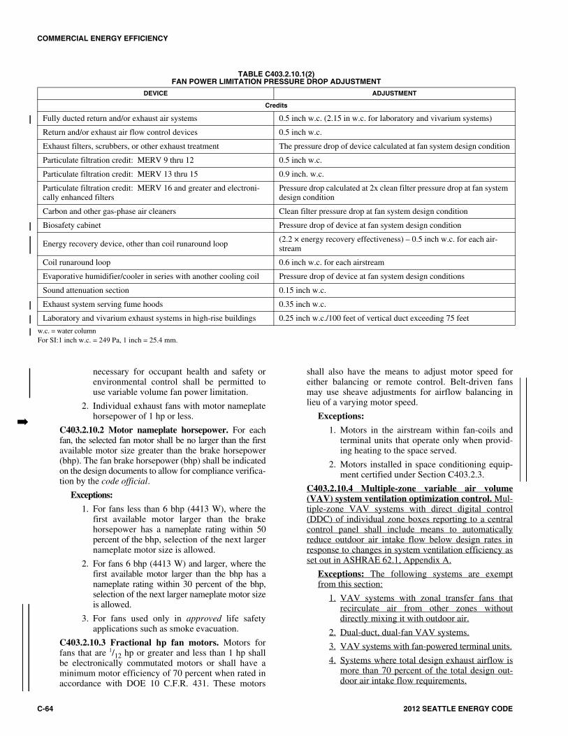
COMMERCIAL ENERGY EFFICIENCY
C-64 2012 SEATTLE ENERGY CODE
necessary for occupant health and safety orenvironmental control shall be permitted touse variable volume fan power limitation.
2. Individual exhaust fans with motor nameplatehorsepower of 1 hp or less.
C403.2.10.2 Motor nameplate horsepower. For eachfan, the selected fan motor shall be no larger than the firstavailable motor size greater than the brake horsepower(bhp). The fan brake horsepower (bhp) shall be indicatedon the design documents to allow for compliance verifica-tion by the code official.
Exceptions:
1. For fans less than 6 bhp (4413 W), where thefirst available motor larger than the brakehorsepower has a nameplate rating within 50percent of the bhp, selection of the next largernameplate motor size is allowed.
2. For fans 6 bhp (4413 W) and larger, where thefirst available motor larger than the bhp has anameplate rating within 30 percent of the bhp,selection of the next larger nameplate motor sizeis allowed.
3. For fans used only in approved life safetyapplications such as smoke evacuation.
C403.2.10.3 Fractional hp fan motors. Motors forfans that are 1/12 hp or greater and less than 1 hp shallbe electronically commutated motors or shall have aminimum motor efficiency of 70 percent when rated inaccordance with DOE 10 C.F.R. 431. These motors
shall also have the means to adjust motor speed foreither balancing or remote control. Belt-driven fansmay use sheave adjustments for airflow balancing inlieu of a varying motor speed.
Exceptions:
1. Motors in the airstream within fan-coils andterminal units that operate only when provid-ing heating to the space served.
2. Motors installed in space conditioning equip-ment certified under Section C403.2.3.
C403.2.10.4 Multiple-zone variable air volume(VAV) system ventilation optimization control. Mul-tiple-zone VAV systems with direct digital control(DDC) of individual zone boxes reporting to a centralcontrol panel shall include means to automaticallyreduce outdoor air intake flow below design rates inresponse to changes in system ventilation efficiency asset out in ASHRAE 62.1, Appendix A.
Exceptions: The following systems are exemptfrom this section:
1. VAV systems with zonal transfer fans thatrecirculate air from other zones withoutdirectly mixing it with outdoor air.
2. Dual-duct, dual-fan VAV systems.
3. VAV systems with fan-powered terminal units.
4. Systems where total design exhaust airflow ismore than 70 percent of the total design out-door air intake flow requirements.
�
TABLE C403.2.10.1(2)FAN POWER LIMITATION PRESSURE DROP ADJUSTMENT
w.c. = water columnFor SI:1 inch w.c. = 249 Pa, 1 inch = 25.4 mm.
DEVICE ADJUSTMENT
Credits
Fully ducted return and/or exhaust air systems 0.5 inch w.c. (2.15 in w.c. for laboratory and vivarium systems)
Return and/or exhaust air flow control devices 0.5 inch w.c.
Exhaust filters, scrubbers, or other exhaust treatment The pressure drop of device calculated at fan system design condition
Particulate filtration credit: MERV 9 thru 12 0.5 inch w.c.
Particulate filtration credit: MERV 13 thru 15 0.9 inch. w.c.
Particulate filtration credit: MERV 16 and greater and electroni-cally enhanced filters
Pressure drop calculated at 2x clean filter pressure drop at fan system design condition
Carbon and other gas-phase air cleaners Clean filter pressure drop at fan system design condition
Biosafety cabinet Pressure drop of device at fan system design condition
Energy recovery device, other than coil runaround loop (2.2 × energy recovery effectiveness) – 0.5 inch w.c. for each air-stream
Coil runaround loop 0.6 inch w.c. for each airstream
Evaporative humidifier/cooler in series with another cooling coil Pressure drop of device at fan system design conditions
Sound attenuation section 0.15 inch w.c.
Exhaust system serving fume hoods 0.35 inch w.c.
Laboratory and vivarium exhaust systems in high-rise buildings 0.25 inch w.c./100 feet of vertical duct exceeding 75 feet
COMMERCIAL ENERGY EFFICIENCY
2012 SEATTLE ENERGY CODE C-65
C403.2.10.5 Multiple-zone VAV system outdoor air-flow control. Multiple-zone VAV systems with a mini-mum outside air requirement of 5,000 cfm (2360 L/s)or greater shall be equipped with a device capable ofmeasuring outdoor airflow intake under all load condi-tions. The system shall be capable of increasing orreducing the outdoor airflow intake based on feedbackfrom zonal systems as required by SectionsC403.2.10.4 and C403.2.5.1.
Exceptions:
1. Systems that meet all of the following areexempt from this section:
1.1. No spaces served by the systemrequire demand control ventilation perSection C403.2.5.1.
1.2. The system meets one of the exceptionsto Section C403.2.10.4.
1.3. The system complies with Section403.6 of the International MechanicalCode.
2. Systems where total design exhaust airflow ismore than 70 percent of the total design out-door air intake flow requirements are exemptfrom this section.
C403.2.11 Heating outside a building. Systems installed toprovide heat outside a building shall be radiant systems.
Such heating systems shall be controlled by an occupancysensing device or a timer switch, so that the system is auto-matically deenergized when no occupants are present inthe area heated by each individual device for a period notto exceed one hour.
C403.2.12 System criteria. For fan and pump motors((7.5)) 5 hp and greater including motors in or serving cus-tom and packaged air handlers serving variable air volumefan systems, constant volume fans, parking garage ventila-tion fans, heating and cooling hydronic pumping systems,pool and service water pumping systems, domestic waterpressure boosting systems, cooling tower fan, and otherpump or fan motors where variable flows are required,there shall be:
1. Variable speed drives; or
2. Other controls and devices that will result in fan andpump motor demand of no more than 30 percent ofdesign wattage at 50 percent of design air volumefor fans when static pressure set point equals one-third of the total design static pressure, and 50 per-cent of design water flow for pumps, based on man-ufacturer’s certified test data. Variable inlet vanes,throttling valves (dampers), scroll dampers orbypass circuits shall not be allowed.
Exception: Variable speed devices are not required formotors that serve:
1. Fans or pumps in packaged equipment wherevariable speed drives are not available as a fac-tory option from the equipment manufacturer.
2. Fans or pumps that are required to operate onlyfor emergency fire-life-safety events (e.g., stair-well pressurization fans, elevator pressurizationfans, fire pumps, etc.).
See Seattle Building Code, Section 3016.15 forenergy efficiency requirements for ventilation fan sys-tems in elevators.
C403.2.12.1 Heat rejection equipment. The require-ments of this section apply to heat rejection equipmentused in comfort cooling systems such as air-cooledcondensers, open cooling towers, closed-circuit coolingtowers, and evaporative condensers.
Exception: Heat rejection devices included as anintegral part of equipment listed in TablesC403.2.3(1) through C403.2.3(3).
Heat rejection equipment shall have a minimum effi-ciency performance not less than values specified inTable C403.2.3(8). These requirements apply to all pro-peller, axial fan and centrifugal fan cooling towers.Table C403.2.3(8) specifies requirements for air-cooledcondensers that are within rating conditions specifiedwithin the table.
Cooling towers serving chilled water systems shallbe selected to maintain a return condenser water tem-perature to the tower of 86°F (30°C) or less at peakdesign conditions.
Exception: In existing buildings where physicalconstraints preclude a change from the originaldesign, replacement cooling towers of the same orsmaller capacity are exempt from this requirement.
Hydronic heat pump and other cooling andrefrigeration equipment, including but not limited toicemakers and walk-in coolers, shall not use domes-tic water only one time before dumping it to waste(no single pass water cooling systems are allowed).
Exceptions:
1. Replacement of existing icemakers is exemptfrom this requirement.
2. Use of single pass cooling for medical and den-tal equipment during power outages and otheremergencies is exempt from this requirement.
C403.2.12.1.1 Variable flow controls. Coolingtower fans 7.5 hp and greater shall have controldevices that vary flow by controlling the leavingfluid temperature or condenser temperature/pressureof the heat rejection device.
C403.2.12.1.2 Limitation on centrifugal fan cool-ing towers. Open cooling towers with a combinedrated capacity of 1,100 gpm (69 L/s) and greater at95°F (35°C) condenser water return, 85°F (29°C)condenser water supply and 75°F (24°C) outdoorwet-bulb temperature shall meet the energy efficiencyrequirement for axial fan open circuit cooling towers.
Exception: Open circuit cooling towers that areducted (inlet or discharge) ((or have externalsound attenuation that requires)) and require
1414141414

COMMERCIAL ENERGY EFFICIENCY
C-66 2012 SEATTLE ENERGY CODE
external static pressure capability or open circuitcooling towers that have external sound attenua-tion.
C403.2.12.2 Large volume fan systems. Single ormultiple fan systems serving a zone or adjacent zoneswithout separating walls with total air flow over 10,000cfm (4710 L/s) are required to reduce airflow based onspace thermostat heating and cooling demand. A vari-able speed drive shall reduce airflow to a maximum 75percent of peak airflow or minimum ventilation airrequirement as required by Section 403 of the Interna-tional Mechanical Code, whichever is greater.
Exceptions:
1. Systems where the function of the supply air isfor purposes other than temperature control,such as maintaining specific humidity levelsor supplying an exhaust system.
2. Dedicated outdoor air supply unit(s) with heatrecovery where airflow is equal to the mini-mum ventilation requirements and other fanscycle off unless heating or cooling is required.
3. An area served by multiple units where desig-nated ventilation units have 50 percent or lessof total area airflow and nonventilation unitfans cycle off when heating or cooling is notrequired.
All air-conditioning equipment and air-handlingunits with direct expansion cooling and a coolingcapacity at AHRI conditions greater than or equal to110,000 Btu/h (32 241 W) that serve single zones shallhave their supply fans controlled by two-speed motorsor variable speed drives. At cooling demands less thanor equal to 50 percent, the supply fan controls shall beable to reduce the airflow to no greater than the largerof the following:
1. Two-thirds of the full fan speed; or
2. The volume of outdoor air required to meet theventilation requirements of Section 403 of theInternational Mechanical Code.
C403.2.13 Electric motor efficiency. Design A and Bsquirrel-cage, T-frame induction permanently wired poly-phase motors of 1 hp or more having synchronous speedsof 3,600, 1,800 and 1,200 rpm shall have a nominal full-load motor efficiency no less than the corresponding val-ues for energy efficient motors provided in NEMA Stan-dard MG-1.
Exceptions:
1. Motors used in systems designed to use morethan one speed of a multi-speed motor.
2. Motors used as a component of the equipmentmeeting the minimum equipment efficiencyrequirements of Section C403.2.3 and TablesC403.2.3(1) through C403.2.3(9) provided thatthe motor input is included when determining theequipment efficiency.
3. Motors that are an integral part of specializedprocess equipment.
4. Where the motor is integral to a listed piece ofequipment for which no complying motor hasbeen approved.
Fan motors less than 1 hp in series terminal units and infan-coil units shall be electronically commutated motors,or shall have a minimum motor efficiency of ((65)) 70 per-cent when rated in accordance with NEMA Standard MG-1 at full load rating conditions.
C403.3 Simple HVAC systems and equipment (Prescrip-tive). This section applies to unitary or packaged HVACsystems listed in Tables C403.2.3(1) through C403.2.3(8),each serving one zone and controlled by a single thermostatin the zone served. It also applies to two-pipe heating sys-tems serving one or more zones, where no cooling system isinstalled.
To qualify as a simple system, systems shall have noactive humidification or simultaneous heating and coolingand shall be one of the following:
1. Air cooled, constant volume packaged equipment,which provide heating, cooling or both, and require onlyexternal connection to duct work and energy serviceswith cooling capacity of 135,000 Btu/h (39 568 W) orless.
2. Air cooled, constant volume split systems, which pro-vide heating, cooling or both, with cooling capacity of84,000 Btu/h (24 620 W) or less.
3. Heating only systems which have a capacity of lessthan 1,000 cfm (471 L/s) or which have a minimumoutside air supply of less than 30 percent of the total aircirculation.
The combined airflow rate of all simple systems servingsingle rooms must be less than 10,000 cfm (4710 L/s) or theydo not qualify as simple systems.
C403.3.1 Economizers. Each cooling system that has a fanshall include an air economizer meeting the requirementsof Sections C403.3.1.1 through C403.3.1.1.4.
Exception: Economizers are not required for the sys-tems listed below.
1. Qualifying small equipment: This exception shallnot be used for unitary cooling equipmentinstalled outdoors or in a mechanical room adja-cent to the outdoors. This exception is allowed tobe used for other cooling units and split systemswith a total cooling capacity rated in accordancewith Section C403.2.3 of less than 33,000 Btu/h(9672 W) (hereafter referred to as qualifyingsmall systems) provided that these are high-effi-ciency cooling equipment with SEER and EERvalues more than 15 percent higher than mini-mum efficiencies listed in Tables C403.2.3(1)through (3), in the appropriate size category,using the same test procedures. Equipment shallbe listed in the appropriate certification programto qualify for this exception. The total capacity of
�

COMMERCIAL ENERGY EFFICIENCY
2012 SEATTLE ENERGY CODE C-67
all qualifying small equipment without econo-mizers shall not exceed 72,000 Btu/h (21 103 W)per building, or 5 percent of its air economizercapacity, whichever is greater. That portion of theequipment serving residential occupancies is notincluded in determining the total capacity of allunits without economizers in a building. Redun-dant units are not counted in the capacity limita-tions. This exception shall not be used for theshell-and-core permit or for the initial tenantimprovement or for Total Building Performance.
2. Systems with dehumidification that affect othersystems so as to increase the overall buildingenergy consumption. New humidification equip-ment shall comply with Section C403.2.3.4.
3. For residential occupancies, cooling unitsinstalled outdoors or in a mechanical room adja-cent to outdoors with a total cooling capacity lessthan 20,000 Btu/h (5862 W) and other coolingunits with a total cooling capacity less than 54,000Btu/h (15 827 W) provided that these are high-efficiency cooling equipment with IEER, SEER,and EER values more than 15 percent higher thanminimum efficiencies listed in TablesC403.2.3(1) through (10), in the appropriate sizecategory, using the same test procedures. Equip-ment shall be listed in the appropriate certificationprogram to qualify for this exception. For splitsystems, compliance is based on the coolingcapacity of individual fan coil units.
4. Where the cooling efficiency meets or exceedsthe efficiency requirements in Table C403.3.1(2).
5. Equipment used to cool any dedicated serverroom, electronic equipment room or telecomswitch room provided the system complies withException 5 of Section C403.4.1. The total allow-ance for equipment utilizing Exception 5 of Sec-tion C403.4.1 includes the sum of both simpleand complex systems.
TABLE C403.3.1(1)RESERVED
TABLE C403.3.1(2)EQUIPMENT EFFICIENCY PERFORMANCE
EXCEPTION FOR ECONOMIZERS
C403.3.1.1 Air economizers. Air economizers shallcomply with Sections C403.3.1.1.1 through C403.3.1.1.4.
C403.3.1.1.1 Design capacity. Air economizer sys-tems shall be capable of modulating outdoor air andreturn air dampers to provide up to 100 percent of thedesign supply air quantity as outdoor air for cooling.
C403.3.1.1.2 Control signal. Economizer dampersshall be capable of being sequenced with the mechan-ical cooling equipment and shall not be controlled byonly mixed air temperature. Air economizers on sys-tems with cooling capacity greater than 65,000 Btu/h(19 051 W) shall be capable of providing partial cool-ing even when additional mechanical cooling isrequired to meet the remainder of the cooling load.
Exception: The use of mixed air temperaturelimit control shall be permitted for systems thatare both controlled from space temperature (suchas single-zone systems) and having coolingcapacity less than 65,000 Btu/h (19 051 W).
C403.3.1.1.3 High-limit shutoff. Air economizersshall be capable of automatically reducing outdoorair intake to the design minimum outdoor air quan-tity when outdoor air intake will no longer reducecooling energy usage. High-limit shutoff controltypes for specific climates shall be chosen fromTable C403.3.1.1.3(1). High-limit shutoff controlsettings for these control types shall be those speci-fied in Table C403.3.1.1.3(2).
C403.3.1.1.4 Relief of excess outdoor air. Systemsshall be capable of relieving excess outdoor air dur-ing air economizer operation to prevent over-pres-surizing the building. The relief air outlet shall belocated to avoid recirculation into the building.
C403.3.2 Hydronic system controls. Hydronic systems of atleast 300,000 Btu/h (87 930 W) design output capacity sup-plying heated and chilled water to comfort conditioning sys-tems shall include controls that meet the requirements ofSection C403.4.3.
C403.3.3 Single zone variable-air-volume controls.HVAC systems shall have variable airflow controls as fol-lows:
1. Supply fans for air handling and fan coil units withchilled-water cooling coils and supply fans withmotors greater than or equal to 5 hp shall be con-trolled by variable-speed drives or electronically-commutated motors. At cooling demands less thanor equal to 50 percent, the supply fan controls shallbe able to reduce the airflow to no greater than thelarger of the following:
1.1. One-half of the full fan speed; or
1.2. The volume of outdoor air required to meet theventilation requirements of the InternationalMechanical Code.
2. Supply fans for air-conditioning equipment and airhandling units with direct expansion cooling and acooling capacity greater than or equal to 110,000Btu/h (32 kW) that serve single zones shall be con-trolled by variable-speed drives or electronically-commutated motors. Cooling capacity shall bedetermined at the rating conditions in the AHRIstandard appropriate to the equipment. At coolingdemands less than or equal to 50 percent, the supply
CLIMATE ZONES
COOLING EQUIPMENT PERFORMANCE IMPROVEMENT (EER OR IPLV)
2B 10% Efficiency Improvement
3B 15% Efficiency Improvement
4B 20% Efficiency Improvement
4C 64% Efficiency Improvement
>
>

COMMERCIAL ENERGY EFFICIENCY
C-68 2012 SEATTLE ENERGY CODE
fan controls shall be able to reduce the airflow to nogreater than the larger of the following:
2.1. Two-thirds of the full fan speed; or
2.2. The volume of outdoor air required to meet theventilation requirements of the InternationalMechanical Code.
C403.4 Complex HVAC systems and equipment (Pre-scriptive). This section applies to HVAC equipment and sys-tems not covered in Section C403.3.
For buildings with a total equipment cooling capacity of300 tons (105 kw) and above, the equipment shall complywith one of the following:
1. No one unit shall have a cooling capacity of more thantwo-thirds of the total installed cooling equipmentcapacity;
2. The equipment shall have a variable speed drive; or
3. The equipment shall have multiple compressors.
TABLE C403.3.1.1.3(1)HIGH-LIMIT SHUTOFF CONTROL OPTIONS FOR AIR ECONOMIZERS
a. Electronic enthalpy controllers are devices that use a combination of humidity and dry-bulb temperature in their switching algorithm.
CLIMATE ZONES ALLOWED CONTROL TYPES PROHIBITED CONTROL TYPES
1B, 2B, 3B, 3C, 4B, 4C, 5B, 5C, 6B, 7, 8
Fixed dry bulbDifferential dry bulbElectronic enthalpya Differential enthalpy
Dew-point and dry-bulb temperatures
Fixed enthalpy
1A, 2A, 3A, 4A
Fixed dry bulbFixed enthalpy
Electronic enthalpya
Differential enthalpyDew-point and dry-bulb temperatures
Differential dry bulb
All other climates
Fixed dry bulbDifferential dry bulb
Fixed enthalpyElectronic enthalpya
Differential enthalpyDew-point and dry-bulb temperatures
—
TABLE C403.3.1.1.3(2)HIGH-LIMIT SHUTOFF CONTROL SETTING FOR AIR ECONOMIZERS
For SI: °C = (°F - 32) × 5/9, 1 Btu/lb = 2.33 kJ/kg.a. At altitudes substantially different than sea level, the Fixed Enthalpy limit shall be set to the enthalpy value at 75°F and 50-percent relative humidity. As an
example, at approximately 6,000 feet elevation the fixed enthalpy limit is approximately 30.7 Btu/lb. b. Setpoint “A” corresponds to a curve on the psychometric chart that goes through a point at approximately 75°F and 40-percent relative humidity and is nearly
parallel to dry-bulb lines at low humidity levels and nearly parallel to enthalpy lines at high humidity levels.
DEVICE TYPE CLIMATE ZONE REQUIRED HIGH LIMIT(ECONOMIZER OFF WHEN):
EQUATION DESCRIPTION
Fixed dry bulb
1B, 2B, 3B, 3C, 4B, 4C, 5B, 5C, 6B, 7, 8
TOA > 75°F Outdoor air temperature exceeds 75°F
5A, 6A, 7A TOA > 70°F Outdoor air temperature exceeds 70°F
All other zones TOA > 65°F Outdoor air temperature exceeds 65°F
Differential dry bulb1B, 2B, 3B, 3C, 4B, 4C, 5A,
5B, 5C, 6A, 6B, 7, 8 TOA > TRAOutdoor air temperature exceeds
return air temperature
Fixed enthalpy All hOA > 28 Btu/lba Outdoor air enthalpy exceeds 28 Btu/lb of dry aira
Electronic Enthalpy All (TOA, RHOA) > A Outdoor air temperature/RH exceeds the “A” setpoint curveb
Differential enthalpy All hOA > hRAOutdoor air enthalpy exceeds
return air enthalpy
Dew-point and dry bulb temperatures
All DPOA > 55°F or TOA > 75°F Outdoor air dry bulb exceeds 75°F or outside dew point exceeds 55°F (65 gr/lb)

COMMERCIAL ENERGY EFFICIENCY
2012 SEATTLE ENERGY CODE C-69
C403.4.1 Economizers. Air economizers shall be pro-vided on all new systems including those serving computerserver rooms, electronic equipment, radio equipment, andtelephone switchgear. Economizers shall comply with Sec-tions C403.4.1.1 through C403.4.1.4.
Exceptions:
1. Water-cooled refrigeration equipment servingchilled beams and chilled ceiling space coolingsystems only which are provided with a watereconomizer meeting the requirements of SectionsC403.4.1 through C403.4.1.4. Water economizercapacity per building shall not exceed 500 tons(176 kw). This exception shall not be used forTotal Building Performance.
2. Systems complying with all of the following cri-teria:
2.1. Consist of multiple water source heatpumps connected to a common water loop;
2.2. Have a minimum of 60 percent air econo-mizer;
2.3. Have water source heat pumps with an EERat least 15 percent higher for cooling and aCOP at least 15 percent higher for heatingthan that specified in Section C403.2.3;
2.4. Where provided with a dedicated boiler orfurnace for that building, have a centralboiler or furnace efficiency of 90 percentminimum for units up to 199,000 Btu/h (58327 W); and
2.5. Provide heat recovery with a minimum 50percent heat recovery effectiveness asdefined in Section C403.2.6 to preheat theoutside air supply.
3. Chilled water terminal units connected to systemswith chilled water generation equipment with IPLVvalues more than 25 percent higher than minimumpart load efficiencies listed in Table C403.2.3(7), inthe appropriate size category, using the same testprocedures. Equipment shall be listed in the appro-priate certification program to qualify for thisexception. The total capacity of all systems withouteconomizers shall not exceed ((480,000)) 72,000Btu/h (141 kw) per building, or ((20)) 5 percent ofits air economizer capacity, whichever is greater.That portion of the equipment serving Group ROccupancy is not included in determining the totalcapacity of all units without economizers in a build-ing. This exception shall not be used for the initialpermit (this includes any initial permit for the spaceincluding, but not limited to, the shell-and-core per-mit, built-to-suit permit, and tenant improvementpermit) or for Total Building Performance Method.
4. For Group R occupancies, cooling units installedoutdoors or in a mechanical room adjacent to out-doors with a total cooling capacity less than 20,000
Btu/h (5862 W) and other cooling units with a totalcooling capacity less than 54,000 Btu/h (15 827 W)provided that these are high-efficiency coolingequipment with SEER and EER values more than15 percent higher than minimum efficiencies listedin Tables C403.2.3(1) through (3), in the appropri-ate size category, using the same test procedures.PTAC and PTHP units with capacities no greaterthan 8,300 Btu/h (2433 W) are permitted for the pur-poses of this exception if they have EER values aminimum of 4 percent higher than the minimumefficiencies listed in Table C403.2.3(3), in theappropriate size category, using the same test proce-dures. Equipment shall be listed in the appropriatecertification program to qualify for this exception.For split systems and VRF systems, compliance isbased on the cooling capacity of individual fan coilunits.
5. Equipment used to cool any dedicated serverroom, electronic equipment room or telecomswitch room provided that they completely com-ply with Option a, b, ((or)) c, d or e in the tablebelow. The total capacity of all qualifying sys-tems without economizers shall not exceed240,000 Btu/h (70 344 W) per building or 10 per-cent of its air economizer capacity, whichever isgreater. This exception shall not be used for TotalBuilding Performance.
6. Variable refrigerant flow (VRF) systems, multiple-zone split-system heat pumps, consisting of multi-ple, individually metered indoor units with multi-speed fan motors, served on a single commonrefrigeration circuit with an exterior reverse-cycleheat pump with variable speed compressor(s) andvariable speed condenser fan(s). These systemsshall also be capable of providing simultaneousheating and cooling operation, where in all roomswith VRF units recovered energy from the indoorunits operating in one mode can be transferred toone or more indoor units operating in the othermode, and shall serve at least 20 percent internal[no perimeter wall within 12 feet (3658 mm)] and20 percent perimeter zones (as determined by con-ditioned floor area) and the outdoor unit shall be atleast 65,000 Btu/h (19 051 W) in total capacity.Systems utilizing this exception shall have 50 per-cent heat recovery effectiveness as defined by Sec-tion C403.2.6 on the outside air. For the purposesof this exception, dedicated server rooms, elec-tronic equipment rooms or telecom switch roomsare not considered perimeter zones and shall notexceed 20 percent of the floor area served by theVRF system. This exception shall be limited tobuildings of 60,000 square feet (5574 m2) and less.
7. Medical and laboratory equipment that is directlywater-cooled and is not dependent upon space airtemperature.

COMMERCIAL ENERGY EFFICIENCY
C-70 2012 SEATTLE ENERGY CODE
C403.4.1.1 Design capacity. Water economizer sys-tems shall be capable of cooling supply air by indirectevaporation and providing up to 100 percent of theexpected system cooling load at outdoor air tempera-tures of 50°F dry bulb (10°C dry bulb)/45°F wet bulb(7.2°C wet bulb) and below.
Exception: Systems in which a water economizer isused and where dehumidification requirements can-not be met using outdoor air temperatures of 50°Fdry bulb (10°C dry bulb)/45°F wet bulb (7.2°C wetbulb) shall satisfy 100 percent of the expected sys-tem cooling load at 45°F dry bulb (7.2°C dry bulb)/40°F wet bulb (4.5°C wet bulb).
C403.4.1.2 Maximum pressure drop. Precoolingcoils and water-to-water heat exchangers used as partof a water economizer system shall either have a water-side pressure drop of less than 15 feet (4572 mm) ofwater or a secondary loop shall be created so that thecoil or heat exchanger pressure drop is not seen by the
circulating pumps when the system is in the normalcooling (noneconomizer) mode.
C403.4.1.3 Integrated economizer control. Econo-mizer systems shall be integrated with the mechanicalcooling system and be capable of providing partialcooling even where additional mechanical cooling isrequired to meet the remainder of the cooling load.
Exceptions:
1. Direct expansion systems that include controlsthat reduce the quantity of outdoor airrequired to prevent coil frosting at the loweststep of compressor unloading, provided thislowest step is no greater than 25 percent of thetotal system capacity.
2. Individual direct expansion units that have arated cooling capacity less than 54,000 Btu/h(15,827 W) and use nonintegrated economizercontrols that preclude simultaneous operationof the economizer and mechanical cooling.
C403.4.1 EXCEPTION 5 TABLE
For SI: 1 British thermal unit per hour = 0.2931 W.a. For a system where all of the cooling equipment is subject to the AHRI standards listed in Tables C403.2.3(1) and C403.2.3(2), the system shall comply with
all of the following (note that if the system contains any cooling equipment that exceeds the capacity limits in Table C403.2.3(1) or C403.2.3(2), or if thesystem contains any cooling equipment that is not included in Table C403.2.3(1) or C403.2.3(2), then the system is not allowed to use this option).
b. The cooling equipment shall have an SEER/EER value and an IEER/IPLV value that each is a minimum of 15 percent greater than the value listed in TablesC403.2.3(1) and C403.2.3(2) [1.15 × values in Tables C403.2.3(1) and C403.2.3(2)].
c. For units with a total cooling capacity over 85,000 Btu/h, the system shall utilize part-load capacity control schemes that are able to modulate to a part-load capac-ity of 50 percent of the load or less that results in the compressor operating at the same or higher EER at part loads than at full load (e.g., minimum of two-stagesof compressor unloading such as cylinder unloading, two-stage scrolls, dual tandem scrolls, but hot gas bypass is not credited as a compressor unloading system).
d. The cooling equipment shall have an SEER/EER value and an IEER/IPLV value that each is a minimum of 5 percent greater than the value listed in TablesC403.2.3(1) and C403.2.3(2) [1.05 × values in Tables C403.2.3(1) and C403.2.3(2)].
e. The system shall include a water economizer in lieu of air economizer. Water economizers shall meet the requirements of Sections C403.4.1.2 throughC403.4.1.4 and be capable of providing the total concurrent cooling load served by the connected terminal equipment lacking airside economizer, at outsideair temperatures of 50°F dry-bulb/45°F wet-bulb and below. For this calculation, all factors including solar and internal load shall be the same as those usedfor peak load calculations, except for the outside temperatures. The equipment shall be served by a dedicated condenser water system unless a nondedicatedcondenser water system exists that can provide appropriate water temperatures during hours when waterside economizer cooling is available.
f. For a system where all cooling equipment is subject to ASHRAE Standard 127.g. The cooling equipment subject to the ASHRAE Standard 127 shall have a((n EER value and an IPLV)) SCOP value that is ((equal or)) a minimum of 10
percent greater than the value listed in Tables C403.2.3(1) and C403.2.3(2) (1.10 x values in these tables) when determined in accordance with the ratingconditions in ASHRAE Standard 127 (i.e., not the rating conditions in AHRI Standard 210/240 or 340/360). This information shall be provided by anindependent third party.
h. For a system with chillers subject to the AHRI standards listed in Table C403.2.3(7) (e.g., a chilled water system with fan coil units).i. The cooling equipment shall have a full-load EER value and an IPLV value that is a minimum of 25 percent greater than the value listed in Table C403.2.3(7)
(1.25 x value in Table C403.2.3(7) or a full-load and IPLV kW/ton that is at least 25 percent lower than the value listed in Table C403.2.3(7) (0.75 x value inTable C403.2.3(7)).
j. For all chillers, the system shall utilize part-load capacity control schemes that are able to modulate to a part-load capacity of 50 percent of the load or less andthat result in the compressor operating at the same or higher EER at part loads than at full load (e.g., minimum of two-stages of compressor unloading such ascylinder unloading, two-stage scrolls, or dual tandem scrolls, but hot gas bypass is not a qualifying compressor unloading system).
k. For air-cooled chillers, the cooling equipment shall have an IPLV/EER value that is a minimum of 10 percent greater than the IPLV/EER value listed in TableC403.2.3(7) (1.10 x values in Table C403.2.3(7)). For water-cooled chillers, the cooling equipment shall have an IPLV kW/ton that is at least 15 percent lowerthan the IPLV kW/ton value listed in Table C403.2.3(7) (0.85 x values in Table C403.2.3(7)).
EQUIPMENT TYPE HIGHER EQUIPMENTEFFICIENCY PART-LOAD CONTROL ECONOMIZER
Option aTables C403.2.3(1)and C403.2.3(2)a + 15%b Required over
85,000 Btu/hc None Required
Option b Tables C403.2.3(1)and C403.2.3(2)a + 5%d Required over
85,000 Btu/hc Waterside Economizer
Option c ASHRAE Standard 127f + 0%g Required over85,000 Btu/hc Waterside Economizer
Option d Table C403.2.3(7)h + 25%i Required for all chillers j None Required
Option e Table C403.2.3(7)h + 10/15%k Required over 85,000 Btu/hc Dedicated waterside economizer
COMMERCIAL ENERGY EFFICIENCY
2012 SEATTLE ENERGY CODE C-71
C403.4.1.4 Economizer heating system impact.HVAC system design and economizer controls shall besuch that economizer operation does not increase thebuilding heating energy use during normal operation.
Exception: Economizers on VAV systems thatcause zone level heating to increase due to a reduc-tion in supply air temperature.
C403.4.2 Variable air volume (VAV) fan control. Indi-vidual VAV fans with motors of 7.5 horsepower (5.6 kW)or greater shall be:
1. Driven by a mechanical or electrical variable speeddrive;
2. Driven by a vane-axial fan with variable-pitchblades; or
3. The fan shall have controls or devices that will resultin fan motor demand of no more than 30 percent oftheir design wattage at 50 percent of design airflowwhen static pressure set point equals one-third of thetotal design static pressure, based on manufacturer’scertified fan data.
C403.4.2.1 Static pressure sensor location. Staticpressure sensors used to control VAV fans shall beplaced in a position such that the controller setpoint isno greater than one-third the total design fan static pres-sure, except for systems with zone reset control com-plying with Section C403.4.2.2. For sensors installeddown-stream of major duct splits, at least one sensorshall be located on each major branch to ensure thatstatic pressure can be maintained in each branch.
C403.4.2.2 Set points for direct digital control. Forsystems with direct digital control of individual zoneboxes reporting to the central control panel, the staticpressure set point shall be reset based on the zonerequiring the most pressure, i.e., the set point is resetlower until one zone damper is nearly wide open.
C403.4.3 Hydronic systems controls. The heating of flu-ids that have been previously mechanically cooled and thecooling of fluids that have been previously mechanicallyheated shall be limited in accordance with SectionsC403.4.3.1 through C403.4.3.3. Hydronic heating systemscomprised of multiple-packaged boilers and designed todeliver conditioned water or steam into a common distri-bution system shall include automatic controls capable ofsequencing operation of the boilers. Hydronic heating sys-tems comprised of a single boiler and greater than 500,000Btu/h (146,550 W) input design capacity shall includeeither a multistaged or modulating burner.
C403.4.3.1 Three-pipe system. Hydronic systems thatuse a common return system for both hot water andchilled water are prohibited.
C403.4.3.2 Two-pipe changeover system. Systems thatuse a common distribution system to supply both heatedand chilled water shall be designed to allow a dead bandbetween changeover from one mode to the other of atleast 15°F (8.3°C) outside air temperatures; be designedto and provided with controls that will allow operation inone mode for at least 4 hours before changing over to the
other mode; and be provided with controls that allowheating and cooling supply temperatures at the change-over point to be no more than 30°F (16.7°C) apart.
C403.4.3.3 Hydronic (water loop) heat pump sys-tems. Hydronic heat pump systems shall comply withSections C403.4.3.3.1 through C403.4.3.3.3.
C403.4.3.3.1 Temperature dead band. Hydronicheat pumps connected to a common heat pump waterloop with central devices for heat rejection and heataddition shall have controls that are capable of provid-ing a heat pump water supply temperature dead bandof at least 20°F (11.1°C) between initiation of heatrejection and heat addition by the central devices.
Exception: Where a system loop temperatureoptimization controller is installed and can deter-mine the most efficient operating temperaturebased on realtime conditions of demand andcapacity, dead bands of less than 20°F (11°C)shall be permitted.
C403.4.3.3.2 Heat rejection. Heat rejection equip-ment shall comply with Sections C403.4.3.3.2.1 andC403.4.3.3.2.2.
Exception: Where it can be demonstrated that aheat pump system will be required to reject heatthroughout the year.
C403.4.3.3.2.1 Climate Zones 3 and 4. For ClimateZones 3 and 4:
1. If a closed-circuit cooling tower is useddirectly in the heat pump loop, either anautomatic valve shall be installed to bypassall but a minimal flow of water around thetower, or lower leakage positive closuredampers shall be provided.
2. If an open-circuit tower is used directly inthe heat pump loop, an automatic valve shallbe installed to bypass all heat pump waterflow around the tower.
3. If an open- or closed-circuit cooling tower isused in conjunction with a separate heatexchanger to isolate the cooling tower fromthe heat pump loop, then heat loss shall becontrolled by shutting down the circulationpump on the cooling tower loop.
C403.4.3.3.2.2 Climate Zones 5 through 8. ForClimate Zones 5 through 8, if an open- or closed-circuit cooling tower is used, then a separate heatexchanger shall be provided to isolate the coolingtower from the heat pump loop, and heat loss shallbe controlled by shutting down the circulationpump on the cooling tower loop and providing anautomatic valve to stop the flow of fluid.
C403.4.3.3.3 Isolation valve. Each hydronic heatpump on the hydronic system having a total pumpsystem power exceeding 10 horsepower (hp) (7.5kW) shall have a two-way (but not three-way) valve.For the purposes of this section, pump system power

COMMERCIAL ENERGY EFFICIENCY
C-72 2012 SEATTLE ENERGY CODE
is the sum of the nominal power demand (i.e., name-plate horsepower at nominal motor efficiency) ofmotors of all pumps that are required to operate atdesign conditions to supply fluid from the heating orcooling source to all heat transfer devices (e.g.,coils, heat exchanger) and return it to the source.This converts the system into a variable flow systemand, as such, the primary circulation pumps shallcomply with the variable flow requirements in Sec-tion C403.4.3.6.
C403.4.3.4 Part load controls. Hydronic systemsgreater than or equal to 300,000 Btu/h (87,930 W) indesign output capacity supplying heated or chilledwater to comfort conditioning systems shall includecontrols that have the capability to:
1. Automatically reset the supply-water temperaturesusing zone-return water temperature, building-return water temperature, or outside air tempera-ture as an indicator of building heating or coolingdemand. The temperature shall be capable of beingreset by at least 25 percent of the design supply-to-return water temperature difference; and
2. Reduce system pump flow by at least 50 percent ofdesign flow rate utilizing adjustable speed drive(s)on pump(s), or multiple-staged pumps where atleast one-half of the total pump horsepower iscapable of being automatically turned off or con-trol valves designed to modulate or step down, andclose, as a function of load, or other approvedmeans.
Hydronic systems serving hydronic heat pumps areexempt from Item 1, and only those hydronic systemswith a total pump system power greater than 3 hp (2.2kW) shall have controls meeting the requirements ofItem 2, above.
C403.4.3.5 Pump isolation. Chilled water plantsincluding more than one chiller shall have the capabil-ity to reduce flow automatically through the chillerplant when a chiller is shut down and automaticallyshut off flow to chillers that are shut down. Chillerspiped in series for the purpose of increased temperaturedifferential shall be considered as one chiller.
Exception: Chillers that are piped in series for thepurpose of increased temperature differential.
Boiler plants including more than one boiler shall havethe capability to reduce flow automatically through theboiler plant when a boiler is shut down and automaticallyshut off flow to ((chillers)) boilers that are shut down.
C403.4.3.6 Variable flow controls. Individual pumpsrequiring variable speed control per Section C403.2.12shall be controlled in one of the following manners:
1. For systems having a combined pump motorhorsepower less than or equal to 20 hp (15 kW)and without direct digital control of individualcoils, pump speed shall be a function of either:
1.1. Required differential pressure; or
1.2. Reset directly based on zone hydronicdemand, or other zone load indicators; or
1.3. Reset directly based on pump power andpump differential pressure.
2. For systems having a combined pump motorhorsepower that exceeds 20 hp (15 kW) orsmaller systems with direct digital control, pumpspeed shall be a function of either:
2.1. The static pressure set point as reset basedon the valve requiring the most pressure; or
2.2. Directly controlled based on zone hydronicdemand.
C403.4.4 Heat rejection equipment fan speed control.Each fan powered by a motor of 7.5 hp (5.6 kW) or largershall have controls that automatically change the fan speedto control the leaving fluid temperature or condensingtemperature/pressure of the heat rejection device.
C403.4.5 Requirements for complex mechanical sys-tems serving multiple zones. Sections C403.4.5.1 throughC403.4.5.4 shall apply to complex mechanical systemsserving multiple zones. Supply air systems serving multiplezones shall be VAV systems which, during periods of occu-pancy, are designed and capable of being controlled toreduce primary air supply to each zone to one of the follow-ing before reheating, recooling or mixing takes place:
1. Thirty percent of the maximum supply air to eachzone.
2. Three hundred cfm (142 L/s) or less where the max-imum flow rate is less than 10 percent of the totalfan system supply airflow rate.
3. The minimum ventilation requirements of Chapter 4of the International Mechanical Code.
4. Minimum flow rates required by applicable codes orstandards for occupant health and safety.
Exception: The following define where individual zonesor where entire air distribution systems are exemptedfrom the requirement for VAV control:
1. Reserved.
2. Zones or supply air systems where at least 75 per-cent of the energy for reheating or for providingwarm air in mixing systems is provided from asite-recovered or site-solar energy source.
3. Zones where special humidity levels are requiredto satisfy process needs.
4. Zones with a peak supply air quantity of 300 cfm(142 L/s) or less and where the flow rate is lessthan 10 percent of the total fan system supply air-flow rate.
5. Zones where the volume of air to be reheated,recooled or mixed is no greater than the volume ofoutside air required to meet the minimum ventila-tion requirements of Chapter 4 of the InternationalMechanical Code.
6. Zones or supply air systems with thermostatic andhumidistatic controls capable of operating in
>
>

COMMERCIAL ENERGY EFFICIENCY
2012 SEATTLE ENERGY CODE C-73
sequence the supply of heating and cooling energyto the zones and which are capable of preventingreheating, recooling, mixing or simultaneous sup-ply of air that has been previously cooled, eithermechanically or through the use of economizersystems, and air that has been previously mechan-ically heated.
C403.4.5.1 Single duct variable air volume (VAV) sys-tems, terminal devices. Single duct VAV systems shalluse terminal devices capable of reducing the supply ofprimary supply air before reheating or recooling takesplace.
C403.4.5.2 Dual duct and mixing VAV systems, ter-minal devices. Systems that have one warm air duct andone cool air duct shall use terminal devices which arecapable of reducing the flow from one duct to a mini-mum before mixing of air from the other duct takesplace.
C403.4.5.3 Reserved.
C403.4.5.4 Supply-air temperature reset controls.Multiple zone HVAC systems shall include controlsthat automatically reset the supply-air temperature inresponse to representative building loads, or to outdoorair temperature. The controls shall be capable of reset-ting the supply air temperature at least 25 percent of thedifference between the design supply-air temperatureand the design room air temperature.
Exceptions:
1. Systems that prevent reheating, recooling ormixing of heated and cooled supply air.
2. Seventy-five percent of the energy for reheat-ing is from site-recovered or site solar energysources.
3. Zones with peak supply air quantities of 300cfm (142 L/s) or less.
C403.4.6 Heat recovery for service water heating. Con-denser heat recovery shall be installed for heating or reheat-ing of service hot water provided the facility operates 24hours a day, the total installed heat capacity of water-cooledsystems exceeds 1,500,000 Btu/hr (440 kw) of heat rejec-tion, and the design service water heating load exceeds250,000 Btu/hr (73 275 W).
The required heat recovery system shall have thecapacity to provide the smaller of:
1. Sixty percent of the peak heat rejection load atdesign conditions; or
2. The preheating required to raise the peak service hotwater draw to 85°F (29°C).
Exceptions:
1. Facilities that employ condenser heat recovery forspace heating or reheat purposes with a heatrecovery design exceeding 30 percent of the peakwater-cooled condenser load at design conditions.
2. Facilities that provide 60 percent of their servicewater heating from site solar or site recoveredenergy or from other sources.
C403.4.7 Hot gas bypass limitation. Cooling systems shallnot use hot gas bypass or other evaporator pressure controlsystems unless the system is designed with multiple steps ofunloading or continuous capacity modulation. The capacityof the hot gas bypass shall be limited as indicated in TableC403.4.7.
Exception: Unitary packaged systems with coolingcapacities not greater than 90,000 Btu/h (26,379 W).
TABLE C403.4.7MAXIMUM HOT GAS BYPASS CAPACITY
For SI: 1 British thermal unit per hour = 0.2931 W.
C403.4.8 Hydronic system design. All chilled water andcondenser water piping shall be designed such that thedesign flow rate in each pipe segment shall not exceed thevalues listed in Table C403.4.8 for the appropriate totalannual hours of operation. Pipe size selections for systemsthat operate under variable flow conditions (e.g., modulat-ing 2-way control valves at coils) and that contain variablespeed pump motors are allowed to be made from the“Variable Flow/ Variable Speed” columns. All others shallbe made from the “Other” columns.
Exception: Design flow rates exceeding the values inTable C403.4.8 are allowed in specific sections of pipeif the pipe is not in the critical circuit at design condi-tions and is not predicted to be in the critical circuitduring more than 30 percent of operating hours.
C403.5 Walk-in coolers and walk-in freezers. Walk-incoolers and walk-in freezers shall comply with all of the fol-lowing:
1. Anti-sweat heaters without anti-sweat heater controlsshall have a total door rail, glass, and frame heaterpower draw of less than or equal to 7.1 watts per squarefoot of door opening for walk-in freezers, and 3.0 wattsper square foot of door opening for walk-in coolers.
2. Anti-sweat heater controls shall reduce the energy useof the anti-sweat heater as a function of the relativehumidity in the air outside the door or to the condensa-tion on the inner glass pane.
3. Evaporator fan motors that are less than 1 horsepowerand less than 460 volts shall use electronically commu-tated motors (brushless direct current motors) or 3-phase motors.
>
RATED CAPACITY MAXIMUM HOT GAS BYPASS CAPACITY(% of total capacity)
≤ 240,000 Btu/h 50
> 240,000 Btu/h 25
Informative Note: The flow rates listed here do notconsider noise or erosion. (Lower flow rates are oftenrecommended for noise sensitive locations.)

COMMERCIAL ENERGY EFFICIENCY
C-74 2012 SEATTLE ENERGY CODE
4. Condenser fan motors that are less than 1 horsepowershall use electronically commutated motors, permanentsplit capacitor-type motors or 3-phase motors.
C403.6 Refrigerated warehouse coolers and refrigeratedwarehouse freezers. Refrigerated warehouse coolers andrefrigerated warehouse freezers shall comply with all of thefollowing:
1. Evaporator fan motors that are less than 1 horsepowerand less than 460 volts shall use electronically commu-tated motors (brushless direct current motors) or 3-phase motors.
2. Condenser fan motors that are less than 1 horsepowershall use electronically commutated motors, permanentsplit capacitor-type motors or 3-phase motors.
3. Evaporator fans shall be variable speed, and the speedshall be controlled in response to space conditions.
Exception: Evaporators served by a single compres-sor without unloading capability.
4. Compressor systems utilized in refrigerated ware-houses shall conform to the following:
4.1. Compressors shall be designed to operate at aminimum condensing temperature of 70°F(21°C) or less.
4.2. The compressor speed of a screw compressorgreater than 50 hp shall be controllable inresponse to the refrigeration load, or the inputpower to the compressor shall be controlled tobe less than or equal to 60 percent of full loadinput power when operated at 50 percent of fullrefrigeration capacity.
Exception: Refrigeration plants with morethan one dedicated compressor per suctiongroup.
C403.7 Compressed air and vacuum air. Compressed airand vacuum air systems shall comply with all of the following:
Exception: Compressed air and vacuum air systems usedfor medical purposes are exempt from this section.
1. Air compressors (50-150 psi), General: Air compres-sors operating at 50-150 psi shall comply with the fol-lowing:
1.1. All water drains shall be “no loss” drains.
1.2. Timed unheated desiccant air driers shall not beallowed.
2. Rotary screw air compressors over 10 hp (50-150 psi):Rotary screw air compressors over 10 hp operating at50-150 psi shall not rely on modulation control andshall have one of the following:
2.1. Receiver capacity greater than three gallons percfm to allow efficient load/unload control;
2.2. Variable speed drive controlled air compressor;or
2.3. Multiple air compressors using a smaller trim-aircompressor to trim. The trim compressor shall usevariable speed drive control or shall use load/unload control with greater than 3-gallon receivercapacity per cfm for the trim air compressor.
C403.8 Commercial food service. The following types ofequipment within the scope of the applicable Energy Starprogram shall comply with the energy-efficiency and water-efficiency criteria required to achieve the Energy Star label:
a. Commercial fryers: Energy Star Program Requirementsfor Commercial Fryers.
b. Commercial hot food holding cabinets: Energy StarProgram Requirements for Hot Food Holding Cabinets.
c. Commercial steam cookers: Energy Star ProgramRequirements for Commercial Steam Cookers.
d. Commercial dishwashers: Energy Star ProgramRequirements for Commercial Dishwashers.
TABLE C403.4.8PIPING SYSTEM DESIGN MAXIMUM FLOW RATE IN GPM1
For SI: 1 inch = 25.4 mm.1. There are no requirements for pipe sizes smaller than the minimum shown in the table or larger than the maximum shown in the table.
≤ = 2,000 hours/yr > 2,000 and ≤ 4,400 hours/year > 4,400 hours/year
Pipe Size(in) Other Variable Flow/
Variable Speed Other Variable Flow/Variable Speed Other Variable Flow/
Variable Speed
2 1/2 120 180 85 130 68 110
3 180 270 140 210 110 170
4 350 530 260 400 210 320
5 410 620 310 470 250 370
6 740 1,100 570 860 440 680
8 1,200 1,800 900 1,400 700 1,100
10 1,800 2,700 1,300 2,000 1,000 1,600
12 2,500 3,800 1,900 2,900 1,500 2,300

COMMERCIAL ENERGY EFFICIENCY
2012 SEATTLE ENERGY CODE C-75
SECTION C404SERVICE WATER HEATING
(MANDATORY)C404.1 General. This section covers the minimum effi-ciency of, and controls for, service water-heating equipmentand insulation of service hot water piping.
C404.2 Service water-heating equipment performanceefficiency. Water-heating equipment and hot water storagetanks shall meet the requirements of Table C404.2. The effi-ciency shall be verified through certification and listedunder an approved certification program, or if no certifica-tion program exists, the equipment efficiency ratings shallbe supported by data furnished by the manufacturer.
C404.3 Temperature controls. Service water-heatingequipment shall be provided with controls to allow a set-point of 110°F (43°C) for equipment serving dwelling unitsand 90°F (32°C) for equipment serving other occupancies.The outlet temperature of lavatories in public facility restrooms shall be limited to 110°F (43°C).
C404.4 Heat traps. Water-heating equipment not suppliedwith integral heat traps and serving noncirculating systemsshall be provided with heat traps on the supply and dis-charge piping associated with the equipment.
C404.5 Water heater installation. Electric water heaters inunconditioned spaces or on concrete floors shall be placedon an incompressible, insulated surface with a minimumthermal resistance of R-10.
C404.6 Pipe insulation. For automatic-circulating hot waterand heat-traced systems, piping shall be insulated with not lessthan 1 inch (25 mm) of insulation having a conductivity notexceeding 0.27 Btu per inch/h × ft2 × °F (1.53 W per 25 mm/m2 × K). The 8 feet (2438 mm) of piping in non-hot-water-sup-ply tefirstmperature maintenance systems served by equipmentwithout integral heat traps shall be insulated with 0.5 inch (12.7mm) of material having a conductivity not exceeding 0.27 Btuper inch/h × ft2 × °F (1.53 W per 25 mm/m2 × K).
Exceptions:
1. Heat-traced piping systems shall meet the insulationthickness requirements per the manufacturer’sinstallation instructions. Untraced piping within aheat traced system shall be insulated with not lessthan 1 inch (25 mm) of insulation having a conduc-tivity not exceeding 0.27 Btu per inch/h × ft2 × °F(1.53 W per 25 mm/m2 × K).
2. Hot water piping that is part of the final pipe run tothe plumbing fixture and is not part of the auto-matic-circulating hot water recirculation path is notrequired to meet the minimum insulation require-ments of C404.6.
C404.7 Reserved. ((Hot water system controls. Circulatinghot water system pumps or heat trace shall be arranged to beturned off either automatically or manually when there is lim-ited hot water demand. Ready access shall be provided to theoperating controls.))
C404.8 Shutoff controls. Systems designed to maintainusage temperatures in hot water pipes, such as circulatinghot water systems or heat traced pipes, shall be equippedwith automatic time switches or other controls to turn offthe system during periods of nonuse.
C404.9 Domestic hot water meters. Each individualdwelling unit in a Group R-2 multi-family residential occu-pancy with central service shall be provided with a domestichot water meter to allow for domestic hot water billingbased on actual domestic hot water usage.
C404.10 Pools and inground permanently installed spas(Mandatory). Pools and inground permanently installedspas shall comply with Sections C404.10.1 throughC404.10.4.
C404.10.1 Heaters. Pool water heaters using electricresistance heating as the primary source of heat are prohib-ited for pools over 2,000 gallons. Heat pump pool heatersshall have a minimum COP of 4.0 at 50°F db, 44.2°F wboutdoor air and 80°F entering water, determined in accor-dance with ((ASHRAE Standard 146)) AHRI Standard1160, Performance Rating of Heat Pump Pool Heaters.Other pool heating equipment shall comply with the appli-cable efficiencies in Section C404.2.3.
All heaters shall be equipped with a readily accessibleon-off switch that is mounted outside of the heater toallow shutting off the heater without adjusting the thermo-stat setting. Gas-fired heaters shall not be equipped withconstant burning pilot lights.
C404.10.2 Time switches. Time switches or other controlmethod that can automatically turn off and on heaters andpumps according to a preset schedule shall be installed onall heaters and pumps. Heaters, pumps and motors thathave built in timers shall be deemed in compliance with thisrequirement.
Exceptions:1. Where public health standards require 24-hour
pump operation.
2. Where pumps are required to operate solar- andwaste-heat-recovery pool heating systems.
C404.10.3 Covers. Heated pools and in-ground perma-nently installed spas shall be provided with a vapor-retar-dant cover on or at the water surface. Pools heated to morethan 90°F (32°C) shall have a pool cover with a minimuminsulation value of R-12, and the sides and bottom of thepool shall also have a minimum insulation value of R-12.
C404.10.4 Heat recovery. Heated indoor swimmingpools, spas or hot tubs with water surface area greater than200 square feet (18.6 m2) shall provide for energy conser-vation by an exhaust air heat recovery system that heatsventilation air, pool water or domestic hot water. The heatrecovery system shall be capable of decreasing the exhaustair temperature at design heating conditions [80°F (27°C)indoor] by 36°F (10°C) in Climate Zones 4C and 5B and48°F (26.7°C) in Climate Zone 6B.
Exception: Pools, spas or hot tubs that include sys-tem(s) that provide equivalent recovered energy on anannual basis through one of the following methods:
1. Renewable energy;
2. Dehumidification heat recovery;
3. Waste heat recovery; or4. A combination of these system sources capable
of providing at least 70 percent of the heatingenergy required over an operating season.
141414141414141414

COMMERCIAL ENERGY EFFICIENCY
C-76 2012 SEATTLE ENERGY CODE
TABLE C404.2MINIMUM PERFORMANCE OF WATER-HEATING EQUIPMENT
For SI: °C = [(°F) - 32]/1.8, 1 British thermal unit per hour = 0.2931 W, 1 gallon = 3.785 L, 1 British thermal unit per hour per gallon = 0.078 W/L. a. Energy factor (EF) and thermal efficiency (Et ) are minimum requirements. In the EF equation, V is the rated volume in gallons. b. Standby loss (SL) is the maximum Btu/h based on a nominal 70°F temperature difference between stored water and ambient requirements. In the SL equation,
Q is the nameplate input rate in Btu/h. In the SL equation for electric water heaters, V is the rated volume in gallons. In the SL equation for oil and gas waterheaters and boilers, V is the rated volume in gallons.
c. Instantaneous water heaters with input rates below 200,000 Btu/h must comply with these requirements if the water heater is designed to heat water totemperatures 180°F or higher.
EQUIPMENT TYPE SIZE CATEGORY(input)
SUBCATEGORY ORRATING CONDITION
PERFORMANCEREQUIREDa, b
TESTPROCEDURE
Water heaters, electric
≤ 12 kW Resistance 0.97 – 0.00 132V, EF DOE 10 CFR Part 430
> 12 kW Resistance 1.73V + 155 SL, Btu/h ANSI Z21.10.3
≤ 24 amps and≤ 250 volts
Heat pump 0.93 – 0.00 132V, EF DOE 10 CFR Part 430
Storage water heaters,gas
≤ 75,000 Btu/h ≥ 20 gal 0.67 – 0.0019V, EF DOE 10 CFR Part 430
> 75,000 Btu/h and≤ 155,000 Btu/h
< 4,000 Btu/h/gal 80% Et
ANSI Z21.10.3
> 155,000 Btu/h < 4,000 Btu/h/gal 80% Et
Instantaneous waterheaters, gas
> 50,000 Btu/h and < 200,000 Btu/h
≥ 4,000 (Btu/h)/gal and < 2 gal 0.62 – 0.00 19V, EF DOE 10 CFR Part 430
≥ 200,000 Btu/hc ≥ 4,000 Btu/h/gal and < 10 gal 80% Et
ANSI Z21.10.3
≥ 200,000 Btu/h≥ 4,000 Btu/h/gal and
≥ 10 gal80% Et
Storage water heaters,oil
≤ 105,000 Btu/h ≥ 20 gal 0.59 – 0.0019V, EF DOE 10 CFR Part 430
> 105,000 Btu/h < 4,000 Btu/h/gal78% Et ANSI Z21.10.3
Instantaneous waterheaters, oil
≤ 210,000 Btu/h≥ 4,000 Btu/h/gal and
< 2 gal 0.59 – 0.0019V, EF DOE 10 CFR Part 430
> 210,000 Btu/h≥ 4,000 Btu/h/gal and
< 10 gal 80% Et
ANSI Z21.10.3
> 210,000 Btu/h ≥ 4,000 Btu/h/gal and≥ 10 gal
78% Et
Hot water supply boilers,gas and oil
≥ 300,000 Btu/h and< 12,500,000 Btu/h
≥ 4,000 Btu/h/gal and < 10 gal 80% Et
ANSI Z21.10.3Hot water supply boilers,
gas≥ 300,000 Btu/h and < 12,500,000 Btu/h
≥ 4,000 Btu/h/gal and≥ 10 gal
80% Et
Hot water supply boilers,oil
> 300,000 Btu/h and < 12,500,000 Btu/h
≥ 4,000 Btu/h/gal and≥ 10 gal
78% Et
Pool heaters, gas and oil All — 78% Et ASHRAE 146
Heat pump pool heaters All — 4.0 COP AHRI 1160
Unfired storage tanks All —Minimum insulation requirement R-12.5
(h · ft2 · °F)/Btu(none)
Q/800 110 V+( )SL, Btu/h
Q/800 110 V+( )SL, Btu/h
Q/800 110 V+( )SL, Btu/h
Q/800 110 V+( )SL, Btu/h
Q/800 110 V+( )SL, Btu/h
Q/800 110 V+( )SL, Btu/h
Q/800 110 V+( )SL, Btu/h

COMMERCIAL ENERGY EFFICIENCY
2012 SEATTLE ENERGY CODE C-77
C404.11 Conservation of water pumping energy. Pumpsfor domestic water systems shall comply with SectionC403.2.12. Water pressure booster systems shall comply withthe following:
1. One or more pressure sensors shall be used to varypump speed or to start and stop pumps, or for both pur-poses. Either the sensor(s) shall be located near the crit-ical fixtures(s) that determine the pressure required, orlogic shall be employed that adjusts the setpoint to sim-ulate operation of remote sensors.
2. No device shall be installed for the purpose of reducingthe pressure of all of the water supplied by any boostersystem pump or booster system, except for safetydevices.
3. No booster system pumps shall operate when there isno service water flow.
SECTION C405ELECTRICAL POWER AND LIGHTING SYSTEMS
C405.1 General (Mandatory). This section covers lighting sys-tem controls, the connection of ballasts, the maximum lightingpower for interior applications, electrical energy consumption,minimum acceptable lighting equipment for exterior applica-tions, and minimum efficiencies for motors and transform-ers.
Exception: Dwelling units within commercial buildingsshall not be required to comply with Sections C405.2through C405.5 provided that a minimum of 75 percent ofthe lamps in permanently installed light fixtures shall behigh efficacy lamps.
Walk-in coolers and walk-in freezers shall comply withC405.10. Refrigerated warehouse coolers and refrigeratedwarehouse freezers shall comply with C405.11.
Escalators and moving walks shall comply with SectionC405.12. Lighting systems shall be commissioned accordingto Section C405.13. Receptacles shall be controlled accord-ing to Section C405.14.
C405.2 Lighting controls (Mandatory). Lighting systems shallbe provided with controls as specified in Sections C405.2.1,C405.2.2, C405.2.3, C405.2.4 and C405.2.5.
Exception: Industrial or manufacturing process areas, asmay be required for production and safety.
C405.2.1 Manual lighting controls. All buildings shallinclude manual lighting controls that meet the require-ments of Sections C405.2.1.1 and C405.2.1.2.
C405.2.1.1 Interior lighting controls. Each areaenclosed by walls or floor-to-ceiling partitions shallhave at least one manual control for the lighting servingthat area. The required controls shall be located withinthe area served by the controls or be a remote switch thatidentifies the lights served and indicates their status.
Exceptions:
1. Areas designated as security or emergencyareas that need to be continuously lighted.
2. Lighting in stairways or corridors that are ele-ments of the means of egress.
3. Stairwells and parking garages are not per-mitted to have a wall-mounted manualswitch.
C405.2.1.2 Light reduction controls. Each area that isrequired to have a manual control shall also allow theoccupant to reduce the connected lighting load in a reason-ably uniform illumination pattern by at least 50 percent.Lighting reduction shall be achieved by one of the follow-ing or other approved method:
1. Controlling all lamps or luminaires;
2. Dual switching of alternate rows of luminaires,alternate luminaires or alternate lamps;
3. Switching the middle lamp in 3-lamp luminairesindependently of the outer lamps; or
4. Switching each luminaire or each lamp.
Exception: Light reduction controls need not beprovided in the following areas and spaces:
1. Areas that have only one luminaire, withrated power less than 100 watts.
2. Areas that are controlled by an occupant-sens-ing device.
3. Corridors, equipment rooms, storerooms, rest-rooms, public lobbies, electrical or mechanicalrooms.
4. Sleeping unit (see Section C405.2.3).
5. Spaces that use less than 0.6 watts per squarefoot (6.5 W/m2).
6. Daylight spaces complying with SectionC405.2.2.3.2.
C405.2.2 Additional lighting controls. Each area that isrequired to have a manual control shall also have controlsthat meet the requirements of Sections C405.2.2.1,C405.2.2.2 and C405.2.2.3.
Exception: Additional lighting controls need not beprovided in the following spaces:
1. Sleeping units.
2. Spaces where patient care is directly provided.
3. Spaces where an automatic shutoff would endan-ger occupant safety or security.
4. Lighting intended for continuous operation.
C405.2.2.1 Automatic time switch control devices.Automatic time switch controls shall be installed tocontrol lighting in all areas of the building.
Automatic time switches shall have a minimum 7day clock and be capable of being set for 7 differentday types per week and incorporate an automatic holi-day “shutoff” feature, which turns off all loads for atleast 24 hours and then resumes normally scheduledoperations. Automatic time switches shall also haveprogram back-up capabilities, which prevent the loss

COMMERCIAL ENERGY EFFICIENCY
C-78 2012 SEATTLE ENERGY CODE
of program and time settings for at least 10 hours, ifpower is interrupted.
Exceptions:
1. Emergency egress lighting does not need to becontrolled by an automatic time switch, exceptas required by Item 7 of Section C405.2.3.
2. Lighting in spaces controlled by occupancysensors does not need to be controlled by auto-matic time switch controls.
The automatic time switch control device shallinclude an override switching device that complies withthe following:
1. The override switch shall be in a readily accessi-ble location;
2. The override switch shall be located where thelights controlled by the switch are visible; or theswitch shall provide a mechanism whichannounces the area controlled by the switch;
3. The override switch shall permit manual operation;
4. The override switch, when initiated, shall permitthe controlled lighting to remain on for a maxi-mum of 2 hours; and
5. Any individual override switch shall control thelighting for a maximum area of ((5,000)) 2,500square feet (((465)) 232 m2).
Exception: Within malls, arcades, auditoriums, sin-gle tenant retail spaces, industrial facilities, pools,gymnasiums, skating rinks and arenas:
1. The time limit shall be permitted to exceed 2hours provided the override switch is a captivekey device; and
2. The area controlled by the override switch is per-mitted to exceed 5,000 square feet (465 m2), butshall not exceed 20,000 square feet (1860 m2).
C405.2.2.2 Occupancy sensors. Occupancy sensorsshall be installed in all classrooms, conference/meetingrooms, employee lunch and break rooms, privateoffices, restrooms, warehouse spaces, storage roomsand janitorial closets, and other spaces 300 square feet(28 m2) or less enclosed by floor-to-ceiling height parti-tions. These automatic control devices shall be installedto automatically turn off lights within 30 minutes of alloccupants leaving the space, and shall either be manualon or shall be controlled to automatically turn the light-ing on to not more than 50 percent power. At initialinstallation, occupancy sensor controls shall be set toturn lights off after 15 minutes unless other thresholdsrequired for safety, security or operational consider-ations are specifically set out in the approved permit.
Exception: Full automatic-on controls shall be per-mitted to control lighting in public corridors, stair-ways, restrooms, primary building entrance areasand lobbies, parking garages, and areas where man-ual-on operation would endanger the safety or secu-rity of the room or building occupants.
C405.2.2.3 Daylight zone control. Daylight zonesshall be designed such that lights in the daylight zoneare controlled independently of general area lightingand are controlled in accordance with SectionC405.2.2.3.2. Each daylight control zone shall notexceed 2,500 square feet (232 m2). Contiguous daylightzones adjacent to vertical fenestration are allowed to becontrolled by a single controlling device serving nomore than 60 lineal feet (18 288 mm) of facade, pro-vided that they do not include zones facing more thantwo adjacent cardinal orientations (i.e., north, east,south, west). The primary daylight zone shall be con-trolled separately from the secondary daylight zone.Daylight zones under skylights more than 15 feet (4572mm) from the perimeter shall be controlled separatelyfrom daylight zones adjacent to vertical fenestration.Controls shall:
1. Control only luminaires within the daylit area.
2. Incorporate time-delay circuits to prevent cyclingof light level changes of less than three minutes.
3. Be set initially at 30 footcandles (323 lux) or notmore than 110 percent of the illuminance levelspecified on the construction documents.
Exception: Daylight zones enclosed by walls orceiling height partitions and containing two or fewerlight fixtures are not required to have a separateswitch for general area lighting.
C405.2.2.3.1 Reserved.
C405.2.2.3.2 Automatic daylighting controls. Set-point and other controls for calibrating the light-ing control device shall be readily accessible.
Daylighting controls device shall be capable ofautomatically reducing the lighting power inresponse to available daylight by either one of thefollowing methods:
1. Continuous dimming using dimming ballastsand daylight-sensing automatic controls thatare capable of reducing the power of generallighting in the daylit zone continuously to lessthan 20 percent of rated power at maximumlight output.
2. Stepped dimming using multi-level switchingand daylight-sensing controls that are capable ofreducing lighting power automatically. Thesystem shall provide a minimum of two controlchannels per zone and be installed in a mannersuch that at least one control step is between 50percent and 70 percent of design lighting powerand another control step is no greater than 35percent of design power, and the system is capa-ble of automatically turning the system off.
Exception: In restaurant dining areas andretail sales areas, light fixtures located lessthan 10 feet (3048 mm) horizontally fromvertical fenestration are not required to becontrolled by daylight sensors where thefenestration adjoins a sidewalk or other
�
>
COMMERCIAL ENERGY EFFICIENCY
2012 SEATTLE ENERGY CODE C-79
outdoor pedestrian area, provided that thelight fixtures are controlled separately fromthe general area lighting.
C405.2.2.3.3 Reserved.
C405.2.3 Specific application controls. Specific applica-tion controls shall be provided for the following:
1. Display and accent light shall be controlled by adedicated control which is independent of the con-trols for other lighting within the room or space.
2. Lighting in cases used for display case purposesshall be controlled by a dedicated control which isindependent of the controls for other lighting withinthe room or space.
3. Hotel and motel sleeping units and guest suites shallhave a master control device at the main room entrythat controls all permanently installed luminaires andswitched receptacles. Where a hotel/motel includesmore than 50 rooms, controls shall be automatic toensure all power to the lights and switched outlets areturned off when the occupant is not in the room.
4. Supplemental task lighting, including permanentlyinstalled under-shelf or under-cabinet lighting, shallbe automatically shut off whenever that space isunoccupied and shall have a control device integralto the luminaires or be controlled by a wall-mountedcontrol device provided the control device is readilyaccessible.
5. Lighting for nonvisual applications, such as plantgrowth and food warming, shall be controlled by adedicated control which is independent of the con-trols for other lighting within the room or space.
6. Lighting equipment that is for sale or for demonstra-tions in lighting education shall be controlled by adedicated control which is independent of the con-trols for other lighting within the room or space.
7. Luminaires serving the exit access and providingmeans of egress illumination required by Section1006.1 of the International Building Code, includ-ing luminaires that function as both normal andemergency means of egress illumination shall becontrolled by a combination of listed emergencyrelay and occupancy sensors, or signal from anotherbuilding control system, that automatically shuts offthe lighting when the areas served by that illumina-tion are unoccupied.
Exception: Means of egress illumination servingthe exit access that does not exceed 0.05 wattsper square foot (0.0045 W/m2) of building area isexempt from this requirement.
8. Each stairway shall have one or more controldevices to automatically reduce lighting power bynot less than 50 percent when no occupants havebeen detected in the stairway for a period notexceeding 30 minutes, and restore lighting to fullpower when occupants enter the stairway. All por-tions of stairways shall remain illuminated to at least
1 footcandle (11 lux) at the walking surface whenthe lighting power is reduced.
9. Lighting in parking garages shall have one or morecontrol devices to automatically reduce lightingpower in any one controlled zone by not less than 50percent when no occupants have been detected inthat zone for a period not exceeding 30 minutes, andrestore lighting to full power when occupants enteror approach the zone. Each lighting zone controlledby occupancy sensors shall be no larger than 7,200square feet (669 m2). Pedestrian occupancy sensorscontrolling any lighting zone are permitted to beconfigured to detect pedestrians no more than 30feet (9144 mm) outside of that zone. Vehicle occu-pancy sensors controlling any lighting zone are per-mitted to be configured to detect vehicles no morethan 60 feet (18 288 mm) outside of that zone.
C405.2.4 Exterior lighting controls. Lighting not desig-nated for dusk-to-dawn operation shall be controlled byeither a combination of a photosensor and a time switch, oran astronomical time switch. Lighting designated for dusk-to-dawn operation shall be controlled by an astronomicaltime switch or photosensor. All time switches shall be capa-ble of retaining programming and the time setting duringloss of power for a period of at least 10 hours.
Building façade lighting shall be automatically shut offbetween midnight or business/facility closing, whicheveris later, and 6 a.m. or business/facility opening, whicheveris earlier. Other lighting, including advertising signage,shall be controlled by a device that automatically reducesthe connected lighting power, on a system-wide basis, byat least 30 percent for at least one of the following condi-tions:
1. From midnight or business/facility closing, which-ever is later, and 6 a.m. or business/facility opening,whichever is earlier; or
2. During any period when no activity has beendetected on the site for a time of no longer than 15minutes.
Exception: Lighting for covered vehicle entrances orexits from buildings or parking structures whererequired for safety, security, or eye adaptation.
C405.2.5 Area controls. The maximum lighting powerthat may be controlled from a single switch or automaticcontrol shall not exceed that which is provided by a 20-ampere circuit loaded to not more than 80 percent. A mastercontrol may be installed provided the individual switchesretain their capability to function independently. Circuitbreakers may not be used as the sole means of switching.
Exception: Areas less than 5 percent of the buildingfootprint for footprints over 100,000 square feet (93 m2).
C405.3 Reserved.
C405.4 Exit signs (Mandatory). Internally illuminated exitsigns shall not exceed 5 watts per side.
C405.5 Interior lighting power requirements (Prescrip-tive). A building complies with this section if its total con-
>
>

COMMERCIAL ENERGY EFFICIENCY
C-80 2012 SEATTLE ENERGY CODE
nected lighting power calculated under Section C405.5.1 isno greater than the interior lighting power calculated underSection C405.5.2.
C405.5.1 Total connected interior lighting power. Thetotal connected interior lighting power (watts) shall be thesum of the watts of all interior lighting equipment as deter-mined in accordance with Sections C405.5.1.1 throughC405.5.1.4. As an option, in areas of the building where allinterior lighting equipment is fed from dedicated lightingbranch circuits, the total connected interior lighting power ispermitted to be calculated as the sum of the capacities of thelighting branch circuits serving those areas. For the purposesof this section, the connected interior lighting power of a 20-ampere circuit is considered to be 16 amperes, and that of a15-ampere circuit is 12 amperes. Use of this alternative andthe limits of the applicable areas shall be clearly documentedon the electrical construction documents.
Exceptions:
1. The connected power associated with the fol-lowing lighting equipment is not included incalculating total connected lighting power.
1.1. Professional sports arena playing fieldlighting.
1.2. Emergency lighting automatically offduring normal building operation.
1.3. Lighting in spaces specifically designedfor use by occupants with special light-ing needs including the visually impairedand other medical and age-related issues.
1.4. Casino gaming areas.
1.5. General area lighting power in indus-trial and manufacturing occupanciesdedicated to the inspection or qualitycontrol of goods and products.
2. Lighting equipment used for the following shallbe exempt provided that it is in addition to gen-eral lighting and is controlled by an independentcontrol device:
2.1. Task lighting for medical and dentalpurposes.
2.2. Display lighting for exhibits in galleries,museums and monuments.
3. Lighting for theatrical purposes, including per-formance, stage, film production and video pro-duction.
4. Lighting for photographic processes.
5. Lighting integral to equipment or instrumenta-tion and is installed by the manufacturer.
6. Task lighting for plant growth or maintenance.
7. Advertising signage or directional signage.
8. In restaurant buildings and areas, lighting forfood warming or integral to food preparationequipment.
9. Lighting equipment that is for sale.
10. Lighting demonstration equipment in lightingeducation facilities.
11. Lighting approved because of safety or emer-gency considerations, inclusive of exit lights.
12. Lighting integral to both open and glass-enclosed refrigerator and freezer cases.
13. Lighting in retail display windows, provided thedisplay area is enclosed by ceiling-height parti-tions.
14. Furniture mounted supplemental task lightingthat is controlled by automatic shutoff.
15. Lighting used for aircraft painting.
C405.5.1.1 Screw lamp holders. The wattage shall bethe maximum labeled wattage of the luminaire.
C405.5.1.2 Low-voltage lighting. The wattage shall bethe specified wattage of the transformer supplying thesystem.
C405.5.1.3 Other luminaires. The wattage of all otherlighting equipment shall be the wattage of the lightingequipment verified through data furnished by the man-ufacturer or other approved sources.
C405.5.1.4 Line-voltage lighting track and plug-inbusway. The wattage shall be:
1. The specified wattage of the luminaires includedin the system with a minimum of 50 W/lin ft.(162 W/lin. m);
2. The wattage limit of the system’s circuit breaker;or
3. The wattage limit of other permanent current lim-iting device(s) on the system.
C405.5.2 Interior lighting power. The total interior light-ing power allowance (watts) is determined according toTable C405.5.2(1) using the Building Area Method, orTable C405.5.2(2) using the Space-by-Space Method, forall areas of the building covered in this permit. For theBuilding Area Method, the interior lighting power allow-ance is the floor area for each building area type listed inTable C405.5.2(1) times the value from Table C405.5.2(1)for that area. For the purposes of this method, an “area”shall be defined as all contiguous spaces that accommo-date or are associated with a single building area type aslisted in Table C405.5.2(1). Where this method is used tocalculate the total interior lighting power for an entirebuilding, each building area type shall be treated as a sepa-rate area. For the Space-by-Space Method, the interiorlighting power allowance is determined by multiplying thefloor area of each space times the value for the space typein Table C405.5.2(2) that most closely represents the pro-posed use of the space, and then summing the lightingpower allowances for all spaces. Tradeoffs among spacesare permitted, except that tradeoffs with covered parkingareas are not permitted. See the Seattle Building Code,Section 3016.15, for energy efficiency requirements forlighting in elevators.
>
>
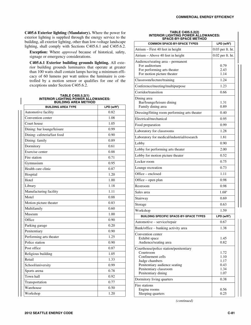
COMMERCIAL ENERGY EFFICIENCY
2012 SEATTLE ENERGY CODE C-81
TABLE C405.5.2(2)INTERIOR LIGHTING POWER ALLOWANCES:
SPACE-BY-SPACE METHOD
(continued)
COMMON SPACE-BY-SPACE TYPES LPD (w/ft2)
Atrium – First 40 feet in height 0.03 per ft. ht.
Atrium – Above 40 feet in height 0.02 per ft. ht.
Audience/seating area – permanentFor auditoriumFor performing arts theaterFor motion picture theater
0.792.431.14
Classroom/lecture/training 1.24
Conference/meeting/multipurpose 1.23
Corridor/transition 0.66
Dining areaBar/lounge/leisure diningFamily dining area
1.310.89
Dressing/fitting room performing arts theater 0.40
Electrical/mechanical 0.95
Food preparation 0.99
Laboratory for classrooms 1.28
Laboratory for medical/industrial/research 1.81
Lobby 0.90
Lobby for performing arts theater 2.00
Lobby for motion picture theater 0.52
Locker room 0.75
Lounge recreation 0.73
Office – enclosed 1.11
Office – open plan 0.98
Restroom 0.98
Sales area 1.68a
Stairway 0.69
Storage 0.63
Workshop 1.59
BUILDING SPECIFIC SPACE-BY-SPACE TYPES LPD (w/ft2)
Automotive – service/repair 0.67
Bank/office – banking activity area 1.38
Convention centerExhibit spaceAudience/seating area
1.450.82
Courthouse/police station/penitentiaryCourtroomConfinement cellsJudge chambersPenitentiary audience seatingPenitentiary classroomPenitentiary dining
1.721.101.170.431.341.07
Dormitory living quarters 0.38
Fire stationsEngine roomsSleeping quarters
0.560.25
C405.6 Exterior lighting (Mandatory). Where the power forexterior lighting is supplied through the energy service to thebuilding, all exterior lighting, other than low-voltage landscapelighting, shall comply with Sections C405.6.1 and C405.6.2.
Exception: Where approved because of historical, safety,signage or emergency considerations.
C405.6.1 Exterior building grounds lighting. All exte-rior building grounds luminaires that operate at greaterthan 100 watts shall contain lamps having a minimum effi-cacy of 60 lumens per watt unless the luminaire is con-trolled by a motion sensor or qualifies for one of theexceptions under Section C405.6.2.
TABLE C405.5.2(1)INTERIOR LIGHTING POWER ALLOWANCES:
BUILDING AREA METHODBUILDING AREA TYPE LPD (w/ft2)
Automotive facility 0.82
Convention center 1.08
Court house 1.05
Dining: bar lounge/leisure 0.99
Dining: cafeteria/fast food 0.90
Dining: family 0.89
Dormitory 0.61
Exercise center 0.88
Fire station 0.71
Gymnasium 0.95
Health care clinic 0.87
Hospital 1.20
Hotel 1.00
Library 1.18
Manufacturing facility 1.11
Motel 0.88
Motion picture theater 0.83
Multifamily 0.60
Museum 1.00
Office 0.90
Parking garage 0.20
Penitentiary 0.90
Performing arts theater 1.25
Police station 0.90
Post office 0.87
Religious building 1.05
Retail 1.33
School/university 0.99
Sports arena 0.78
Town hall 0.92
Transportation 0.77
Warehouse 0.50
Workshop 1.20
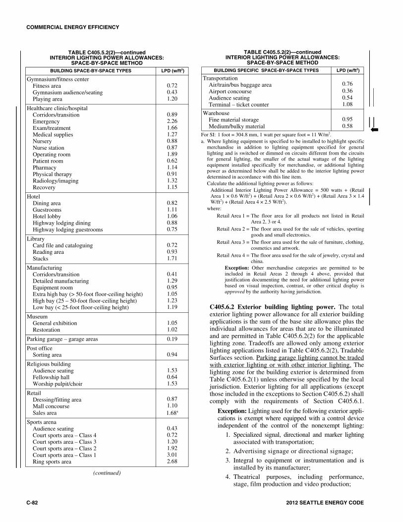
COMMERCIAL ENERGY EFFICIENCY
C-82 2012 SEATTLE ENERGY CODE
C405.6.2 Exterior building lighting power. The totalexterior lighting power allowance for all exterior buildingapplications is the sum of the base site allowance plus theindividual allowances for areas that are to be illuminatedand are permitted in Table C405.6.2(2) for the applicablelighting zone. Tradeoffs are allowed only among exteriorlighting applications listed in Table C405.6.2(2), TradableSurfaces section. Parking garage lighting cannot be tradedwith exterior lighting or with other interior lighting. Thelighting zone for the building exterior is determined fromTable C405.6.2(1) unless otherwise specified by the localjurisdiction. Exterior lighting for all applications (exceptthose included in the exceptions to Section C405.6.2) shallcomply with the requirements of Section C405.6.1.
Exception: Lighting used for the following exterior appli-cations is exempt where equipped with a control deviceindependent of the control of the nonexempt lighting:
1. Specialized signal, directional and marker lightingassociated with transportation;
2. Advertising signage or directional signage;
3. Integral to equipment or instrumentation and isinstalled by its manufacturer;
4. Theatrical purposes, including performance,stage, film production and video production;
TABLE C405.5.2(2)—continuedINTERIOR LIGHTING POWER ALLOWANCES:
SPACE-BY-SPACE METHOD
For SI: 1 foot = 304.8 mm, 1 watt per square foot = 11 W/m2.a. Where lighting equipment is specified to be installed to highlight specific
merchandise in addition to lighting equipment specified for generallighting and is switched or dimmed on circuits different from the circuitsfor general lighting, the smaller of the actual wattage of the lightingequipment installed specifically for merchandise, or additional lightingpower as determined below shall be added to the interior lighting powerdetermined in accordance with this line item.Calculate the additional lighting power as follows:
Additional Interior Lighting Power Allowance = 500 watts + (RetailArea 1 × 0.6 W/ft2) + (Retail Area 2 × 0.6 W/ft2) + (Retail Area 3 × 1.4W/ft2) + (Retail Area 4 × 2.5 W/ft2).
where:Retail Area 1 = The floor area for all products not listed in Retail
Area 2, 3 or 4.Retail Area 2 = The floor area used for the sale of vehicles, sporting
goods and small electronics.Retail Area 3 = The floor area used for the sale of furniture, clothing,
cosmetics and artwork.Retail Area 4 = The floor area used for the sale of jewelry, crystal and
china.Exception: Other merchandise categories are permitted to beincluded in Retail Areas 2 through 4 above, provided thatjustification documenting the need for additional lighting powerbased on visual inspection, contrast, or other critical display isapproved by the authority having jurisdiction.
BUILDING SPECIFIC SPACE-BY-SPACE TYPES LPD (w/ft2)
TransportationAir/train/bus baggage areaAirport concourseAudience seatingTerminal – ticket counter
0.760.360.541.08
WarehouseFine material storageMedium/bulky material
0.950.58 �
TABLE C405.5.2(2)—continuedINTERIOR LIGHTING POWER ALLOWANCES:
SPACE-BY-SPACE METHOD
(continued)
BUILDING SPACE-BY-SPACE TYPES LPD (w/ft2)
Gymnasium/fitness centerFitness areaGymnasium audience/seatingPlaying area
0.720.431.20
Healthcare clinic/hospitalCorridors/transitionEmergencyExam/treatmentMedical suppliesNurseryNurse stationOperating roomPatient roomPharmacyPhysical therapyRadiology/imagingRecovery
0.892.261.661.270.880.871.890.621.140.911.321.15
HotelDining areaGuestroomsHotel lobbyHighway lodging diningHighway lodging guestrooms
0.821.111.060.880.75
LibraryCard file and cataloguingReading areaStacks
0.720.931.71
ManufacturingCorridors/transitionDetailed manufacturingEquipment roomExtra high bay (> 50-foot floor-ceiling height)High bay (25 – 50-foot floor-ceiling height)Low bay (< 25-foot floor-ceiling height)
0.411.290.951.051.231.19
MuseumGeneral exhibitionRestoration
1.051.02
Parking garage – garage areas 0.19
Post officeSorting area 0.94
Religious buildingAudience seatingFellowship hallWorship pulpit/choir
1.530.641.53
RetailDressing/fitting areaMall concourseSales area
0.871.101.68a
Sports arenaAudience seatingCourt sports area – Class 4Court sports area – Class 3Court sports area – Class 2Court sports area – Class 1Ring sports area
0.430.721.201.923.012.68

COMMERCIAL ENERGY EFFICIENCY
2012 SEATTLE ENERGY CODE C-83
5. Athletic playing areas;
6. Temporary lighting;
7. Industrial production, material handling, trans-portation sites and associated storage areas;
8. Theme elements in theme/amusement parks; and
9. Used to highlight features of public monuments andregistered historic landmark structures or buildings.
TABLE C405.6.2(1)EXTERIOR LIGHTING ZONES
C405.6.3 Full cutoff luminaires. For open parking andoutdoor areas and roadways, luminaires mounted morethan 15 feet (4572 mm) above the ground shall be full cut-off luminaires. Full cutoff means a luminaire light distri-bution where zero candela intensity occurs at an angle of90 degrees above nadir and all greater angles from nadir.
C405.7 Electrical energy consumption (Mandatory). Inbuildings having individual dwelling units, provisions shallbe made to determine the electrical energy consumed by eachtenant by separately metering individual dwelling units. Autility tenant meter meets this requirement.
C405.8 Electric motors. All permanently wired polyphasemotors of 1 hp (0.75 kW) or more which are not part of anHVAC system shall comply with Section C403.2.13.
Exceptions:
1. Motors that are an integral part of specialized pro-cess equipment.
2. Where the motor is integral to a listed piece of equip-ment for which no complying motor has been approved.
C405.9 Transformers. The minimum efficiency of a lowvoltage dry-type distribution transformer shall be theClass I Efficiency Levels for distribution transformersspecified in Table 4-2 of NEMA TP-1.
C405.10 Walk-in coolers and walk-in freezers. Walk-incoolers and walk-in freezers shall comply with all of thefollowing:
1. Lights shall use light sources with an efficacy of 40lumens per watt or more, including ballast losses (ifany). Light sources with an efficacy of less than 40lumens per watt, including ballast losses (if any), maybe used in conjunction with a timer or device that turnsoff the lights within 15 minutes of when the walk-incooler or walk-in freezer is not occupied by people.
C405.11 Refrigerated warehouse coolers and refrigeratedwarehouse freezers. Refrigerated warehouse coolers and
refrigerated warehouse freezers shall comply with all of thefollowing:
1. Lights shall use light sources with an efficacy of 40lumens per watt or more, including ballast losses (ifany). Light sources with an efficacy of less than 40lumens per watt, including ballast losses (if any), maybe used in conjunction with a timer or device that turnsoff the lights within 15 minutes of when the refriger-ated warehouse cooler or refrigerated warehousefreezer is not occupied by people.
C405.12 Escalators and moving walks.
C405.12.1 Variable speed escalators. Where variablespeed escalators and moving walks are permitted by theadministrative authority, all escalators and moving walksshall reduce their operating speed to no more than 15 feet(4572 mm) per minute when no passengers have beendetected for a period of time not exceeding three times theamount of time required to transfer a passenger betweenlandings. Such escalators and moving walks shall complywith the requirements of ANSI/ASME A17.1 for variablespeed escalators and moving walks.
Exception: A power factor controller that reducesoperating voltage in response to light loading condi-tions may be provided in place of the variable speedfunction.
C405.12.2 Regenerative drive. Escalators designed eitherfor one-way down operation only or for reversible opera-tion shall have variable frequency regenerative drives thatsupply electrical energy to the building electrical systemwhen loaded with more than five passengers.
C405.13 Electrical power and lighting systems commis-sioning and completion requirements. Electrical powerand lighting systems shall be commissioned and completedin accordance with Section C408.
C405.14 Controlled receptacles. At least 50 percent of all125 volt 15- and 20-ampere receptacles installed in privateoffices, open offices, or classrooms, including those installedin modular partitions and modular office workstation sys-tems, shall be controlled receptacles. In rooms larger than200 square feet (19 m2), a controlled receptacle shall belocated within 72 inches (1.8 m) of each uncontrolled recep-tacle. Controlled receptacles shall be visibly differentiatedfrom standard receptacles and shall be controlled by one ofthe following automatic control devices:
1. An occupant sensor that turns receptacle power offwhen no occupants have been detected for a maximumof 30 minutes, or
2. A time-of-day operated control device that turns recep-tacle power off at specific programmed times and canbe programmed separately for each day of the week.The control device shall be capable of providing anindependent schedule for each portion of the buildingnot to exceed 25,000 square feet (2,323 m2) and not toexceed one full floor. The device shall be capable ofbeing overridden for periods of up to two hours by atimer accessible to occupants. Any individual overrideswitch shall control the controlled receptacles for amaximum area of 5,000 square feet (465 m2). Override
LIGHTING ZONE DESCRIPTION
1Developed areas of national parks, state parks, forest land, and rural areas
2Areas predominantly consisting of residential zoning, neighborhood business districts, light industrial with limited nighttime use and residential mixed use areas
3 All other areas
4 (not used)
((High-activity commercial districts in major metropoli-tan areas as designated by the local land use planning authority))

COMMERCIAL ENERGY EFFICIENCY
C-84 2012 SEATTLE ENERGY CODE
switches for controlled receptacles are permitted tocontrol the lighting within the same area.
Exception: Receptacles designated for specific equipmentrequiring 24-hour operation, for building maintenancefunctions, or for specific safety or security equipment arenot required to be controlled by an automatic control
device and are not required to be located within 72 inches(1.8 m) of a controlled receptacle.
Informative Note: See Section C101.4.3, exceptions 9, 10and 11, regarding controlled receptacle requirements foralterations to existing buildings.
14141414141414
TABLE C405.6.2(2)INDIVIDUAL LIGHTING POWER ALLOWANCES FOR BUILDING EXTERIORS
For SI: 1 foot = 304.8 mm, 1 watt per square foot = W/0.0929 m2.
LIGHTING ZONES
Zone 1 Zone 2 Zone 3 Zone 4
Base Site Allowance (Base allowance is usable in tradable or nontradable surfaces.)
500 W 600 W 750 W 1300 W
Tradable Surfaces (Lighting power densities for uncovered parking areas, building grounds, building entrances and exits, canopies and overhangs and outdoor sales areas are tradable.)
Uncovered Parking Areas
Parking areas and drives 0.04 W/ft2 0.06 W/ft2 0.10 W/ft2 0.13 W/ft2
Building Grounds
Walkways less than10 feet wide 0.7 W/linear foot 0.7 W/linear foot 0.8 W/linear foot 1.0 W/linear foot
Walkways 10 feet wideor greater, plaza areasspecial feature areas
0.14 W/ft2 0.14 W/ft2 0.16 W/ft2 0.2 W/ft2
Stairways 0.75 W/ft2 1.0 W/ft2 1.0 W/ft2 1.0 W/ft2
Pedestrian tunnels 0.15 W/ft2 0.15 W/ft2 0.2 W/ft2 0.3 W/ft2
Building Entrances and Exits
Main entries 20 W/linear foot of door width
20 W/linear footof door width
30 W/linear foot of door width
30 W/linear footof door width
Other doors 20 W/linear foot of door width
20 W/linear foot of door width
20 W/linear foot of door width
20 W/linear foot of door width
Entry canopies 0.25 W/ft2 0.25 W/ft2 0.4 W/ft2 0.4 W/ft2
Sales Canopies
Free-standing andattached 0.6 W/ft2 0.6 W/ft2 0.8 W/ft2 1.0 W/ft2
Outdoor Sales
Open areas (includingvehicle sales lots) 0.25 W/ft2 0.25 W/ft2 0.5 W/ft2 0.7 W/ft2
Street frontage forvehicle sales lots in
addition to “open area”allowance
No allowance 10 W/linear foot 10 W/linear foot 30 W/linear foot
Nontradable Surfaces (Lighting power density calculations for the following applications can be used only for the specific application and cannot be traded between surfaces or with other exterior lighting. The following allowances are in addition to any allowance otherwise permitted in the “Tradable Surfaces” section of this table.)
Building facades No allowance
0.1 W/ft2 for each
illuminated wall orsurface or 2.5 W/linear
foot for each illuminatedwall or surface length
0.15 W/ft2 for eachilluminated wall or
surface or 3.75 W/linearfoot for each illuminated
wall or surface length
0.2 W/ft2 for each illuminated wall or
surface or 5.0 W/linearfoot for each illuminated
wall or surface length
Automated tellermachines and night
depositories
270 W per location plus90 W per additionalATM per location
270 W per location plus90 W per additionalATM per location
270 W per location plus90 W per additionalATM per location
270 W per location plus90 W per additionalATM per location
Entrances and gatehouseinspection stations at
guarded facilities
0.75 W/ft2 of coveredand uncovered area
0.75 W/ft2 of coveredand uncovered area
0.75 W/ft2 of coveredand uncovered area
0.75 W/ft2 of covered and uncovered area
Loading areas for lawenforcement, fire,
ambulance and otheremergency service
vehicles
0.5 W/ft2 of covered and uncovered area
0.5 W/ft2 of covered and uncovered area
0.5 W/ft2 of covered and uncovered area
0.5 W/ft2 of coveredand uncovered area
Drive-up windows/doors 400 W per drive-through 400 W per drive-through 400 W per drive-through 400 W per drive-through
Parking near 24-hourretail entrances 800 W per main entry 800 W per main entry 800 W per main entry 800 W per main entry

COMMERCIAL ENERGY EFFICIENCY
2012 SEATTLE ENERGY CODE C-85
SECTION C406ADDITIONAL EFFICIENCY PACKAGE OPTIONS
Sections C406.1 through C406.4 are not adopted.
SECTION C407 TOTAL BUILDING PERFORMANCE
C407.1 Scope. This section establishes criteria for compli-ance using total building performance. All systems andloads shall be included in determining the total building per-formance including, but not limited to: heating systems,cooling systems, service water heating, fan systems, light-ing power, receptacle loads and process loads.
C407.2 Mandatory requirements. Compliance with thissection requires that the criteria of Sections C402.4, C403.2,C404, ((and)) C405, C408, C409 and C410 be met.
The building permit application for projects utilizing thismethod shall include in one submittal all building andmechanical drawings and all information necessary to verifythat the building envelope and mechanical design for theproject corresponds with the annual energy analysis. If creditis proposed to be taken for lighting energy savings, then anelectrical permit application shall also be submitted andapproved prior to the issuance of the building permit. If creditis proposed to be taken for energy savings from other compo-nents, then the corresponding permit application (e.g., plumb-ing, boiler, etc.) shall also be submitted and approved prior tothe building permit application. Otherwise, components ofthe project that would not be approved as part of a buildingpermit application shall be modeled the same in both the pro-posed building and the standard reference design and shallcomply with the requirements of this code.
C407.3 Performance-based compliance. Compliancebased on total building performance requires that a pro-posed building (proposed design) be shown to have anannual energy consumption based on site energy expressedin Btu and Btu per square foot of conditioned floor area thatis less than or equal to 93 percent of the annual energy con-sumption of the standard reference design.
C407.4 Documentation. Documentation verifying that themethods and accuracy of compliance software tools con-form to the provisions of this section shall be provided tothe code official.
C407.4.1 Compliance report. Building permit submittalsshall include a report that documents that the proposeddesign has annual energy consumption less than or equalto the annual energy consumption of the standard refer-ence design. The compliance documentation shall includethe information listed in Appendix D. ((following infor-mation:
1. Address of the building;
2. An inspection checklist documenting the buildingcomponent characteristics of the proposed design aslisted in Table C407.5.1(1). The inspection checklistshall show the estimated annual energy consumption
for both the standard reference design and the pro-posed design;
3. Name of individual completing the compliancereport; and
4. Name and version of the compliance software tool.
C407.4.2 Additional documentation. The code officialshall be permitted to require the following documents:
1. Documentation of the building component charac-teristics of the standard reference design;
2. Thermal zoning diagrams consisting of floor plansshowing the thermal zoning scheme for standardreference design and proposed design;
3. Input and output report(s) from the energy analysissimulation program containing the complete inputand output files, as applicable. The output file shallinclude energy use totals and energy use by energysource and end-use served, total hours that spaceconditioning loads are not met and any errors orwarning messages generated by the simulation toolas applicable;
4. An explanation of any error or warning messagesappearing in the simulation tool output; and
5. A certification signed by the builder providing thebuilding component characteristics of the proposeddesign as given in Table C407.5.1(1).))
C407.5 Calculation procedure. Except as specified by thissection, the standard reference design and proposed designshall be configured and analyzed using identical methodsand techniques.
C407.5.1 Building specifications. The standard referencedesign and proposed design shall be configured and ana-lyzed as specified by Table C407.5.1(1). TableC407.5.1(1) shall include by reference all notes containedin Table C402.2.
C407.5.2 Thermal blocks. The standard reference designand proposed design shall be analyzed using identical ther-mal blocks as specified in Section C407.5.2.1, C407.5.2.2or C407.5.2.3.
C407.5.2.1 HVAC zones designed. Where HVAC zonesare defined on HVAC design drawings, each HVAC zoneshall be modeled as a separate thermal block.
Exception: Different HVAC zones shall be allowedto be combined to create a single thermal block oridentical thermal blocks to which multipliers areapplied provided:
1. The space use classification is the samethroughout the thermal block.
2. All HVAC zones in the thermal block that areadjacent to glazed exterior walls face the sameorientation or their orientations are within 45degrees (0.79 rad) of each other.
3. All of the zones are served by the same HVACsystem or by the same kind of HVAC system.
>

COMMERCIAL ENERGY EFFICIENCY
C-86 2012 SEATTLE ENERGY CODE
TABLE C407.5.1(1)SPECIFICATIONS FOR THE STANDARD REFERENCE AND PROPOSED DESIGNS
(continued)
BUILDING COMPONENTCHARACTERISTICS STANDARD REFERENCE DESIGN PROPOSED DESIGN
Space use classification Same as proposed
The space use classification shall be chosen in accordance with Table C405.5.2 for all areas of the building covered by this permit. Where the space use classification for a building is not known, the building shall be categorized as an office building.
Roofs
Type: Insulation entirely above deck As proposed
Gross area: same as proposed As proposed
U-factor: from Table C402.1.2 As proposed
Solar absorptance: 0.75 As proposed
Emittance: 0.90 As proposed
Walls, above-grade
Type: Mass wall if proposed wall is mass; otherwise steel-framed wall As proposed
Gross area: same as proposed As proposed
U-factor: from Table C402.1.2 As proposed
Solar absorptance: 0.75 As proposed
Emittance: 0.90 As proposed
Walls, below-grade
Type: Mass wall As proposed
Gross area: same as proposed As proposed
U-Factor: from Table C402.1.2 with insulation layer on interior side of walls As proposed
Floors, above-grade
Type: joist/framed floor As proposed
Gross area: same as proposed As proposed
U-factor: from Table C402.1.2 As proposed
Floors, slab-on-gradeType: Unheated As proposed
F-factor: from Table C402.1.2 As proposed
Doors
Type: Swinging As proposed
Area: Same as proposed As proposed
U-factor: from Table C402.2 As proposed
Vertical fenestration
Area
1. The proposed vertical fenestration area; where the proposed vertical fenestration area is less than 30 percent of above-grade wall area.
2. 30 percent of above-grade wall area; where the proposed vertical fenestration area is 30 percent or more of the above-grade wall area.
As proposed
U-factor: from Table C402.3 for the same framing material as proposed As proposed
SHGC: from Table C402.3 except that for climates with no requirement (NR) SHGC = 0.40 shall be used As proposed
External shading and PF: None As proposed
Skylights
Area
1. The proposed skylight area; where the proposed skylight area is less than ((3)) 5 percent of gross area of roof assembly.
2. ((3)) 5 percent of gross area of roof assembly; where the proposed skylight area is ((3)) 5 percent or more of gross area of roof assembly
As proposed
U-factor: from Table C402.3 As proposed
SHGC: from Table C402.3 except that for climates with no requirement (NR) SHGC = 0.40 shall be used. As proposed
Lighting, interior
The interior lighting power shall be determined in accordance with Section C405.5.2. Where the occupancy of the building is not known, the lighting power density shall be 1.0 Watt per square foot (10.73 W/m2) based on the categorization of buildings with unknown space classification as offices.
Automatic lighting controls (e.g., programmable controls or automatic controls for daylight utilization) shall be modeled in the standard reference design as required by Section C405.
As proposed
Lighting, exteriorThe lighting power shall be determined in accordance with Table C405.6.2(2). Areas and dimensions of tradable and nontradable surfaces shall be the same as proposed.
As proposed

COMMERCIAL ENERGY EFFICIENCY
2012 SEATTLE ENERGY CODE C-87
TABLE C407.5.1(1)—continuedSPECIFICATIONS FOR THE STANDARD REFERENCE AND PROPOSED DESIGNS
(continued)
BUILDING COMPONENTCHARACTERISTICS STANDARD REFERENCE DESIGN PROPOSED DESIGN
Internal gains Same as proposed
Receptacle, motor and process loads shall be modeled and estimated based on the space use classification. All end-use load components within and associated with the building shall be modeled to include, but not be limited to, the following: exhaust fans, parking garage ventilation fans, exterior building lighting, swimming pool heaters and pumps, elevators, escalators, refrigeration equipment and cooking equipment.
Schedules Same as proposed
Operating schedules shall include hourly profiles for daily operation and shall account for variations between weekdays, weekends, holidays and any seasonal operation. Schedules shall model the time-dependent variations in occupancy, illumination, receptacle loads, thermostat settings, mechanical ventilation, HVAC equipment availability, service hot water usage and any process loads. The schedules shall be typical of the proposed building type as determined by the designer and approved by the jurisdiction.
Mechanical ventilation
Same as proposed, except when modeling demand-control ventilation in the proposed design when its use is not required by Section C403.2.5.1 or occupancy sensor ventilation controls when their use is not required by Section C403.2.5.2.
As proposed, in accordance with Section C403.2.5.
Heating systems
Fuel type: same as proposed design As proposed
Equipment typea: from Tables C407.5.1(2) and C407.5.1(3) As proposed
Efficiency: from Tables C403.2.3(2), C403.2.3(3),C403.2.3(4) and C403.2.3(5) As proposed
Preheat coils: If the HVAC system in the proposed design has a preheat coil and a preheat coil can be modeled in the standard reference design, the standard reference design shall be modeled with a preheat coil controlled in the same manner as the proposed design.
Capacityb: Sized proportionally to the capacities in the proposed design based on sizing runs, i.e., the ratio between the capacities used in the annual simulations and the capacities determined by the sizing runs shall be the same for both the proposed design and standard reference design, and shall be established such that no smaller number of unmet heating load hours and no larger heating capacity safety factors are provided than in the proposed design.
Weather conditions used in sizing runs to determine standard reference design equipment capacities may be based either on hourly historical weather files containing typical peak conditions or on design days developed using 99.6% heating design temperatures and 1% dry-bulb and 1% wet-bulb cooling design temperatures.
As proposed
Cooling systems
Fuel type: same as proposed design As proposed
Equipment typec: from Tables C407.5.1(2) and C407.5.1(3) As proposed
Efficiency: from Tables C403.2.3(1), C403.2.3(2) and C403.2.3(3) As proposed
Capacityb: Sized proportionally to the capacities in the proposed design based on sizing runs, i.e., the ratio between the capacities used in the annual simulations and the capacities determined by the sizing runs shall be the same for both the proposed design and standard reference design, and shall be established such that no smaller number of unmet cooling load hours and no larger cooling capacity safety factors are provided than in the proposed design.
As proposed
Economizerd: Same as proposed, in accordance with Section C403.4.1. The high-limit shutoff shall be a dry-bulb switch with a setpoint as determined by Table C403.3.1.1.3(2).
As proposed
Energy recovery Standard reference design systems shall be modeled where required in Section C403.2.6. As proposed
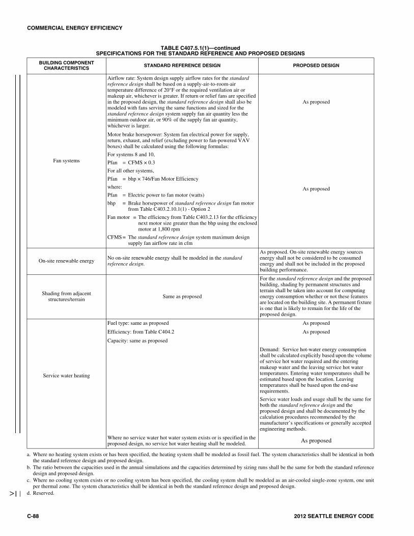
COMMERCIAL ENERGY EFFICIENCY
C-88 2012 SEATTLE ENERGY CODE
TABLE C407.5.1(1)—continuedSPECIFICATIONS FOR THE STANDARD REFERENCE AND PROPOSED DESIGNS
a. Where no heating system exists or has been specified, the heating system shall be modeled as fossil fuel. The system characteristics shall be identical in boththe standard reference design and proposed design.
b. The ratio between the capacities used in the annual simulations and the capacities determined by sizing runs shall be the same for both the standard referencedesign and proposed design.
c. Where no cooling system exists or no cooling system has been specified, the cooling system shall be modeled as an air-cooled single-zone system, one unitper thermal zone. The system characteristics shall be identical in both the standard reference design and proposed design.
d. Reserved.
BUILDING COMPONENTCHARACTERISTICS STANDARD REFERENCE DESIGN PROPOSED DESIGN
Fan systems
Airflow rate: System design supply airflow rates for the standard reference design shall be based on a supply-air-to-room-air temperature difference of 20°F or the required ventilation air or makeup air, whichever is greater. If return or relief fans are specified in the proposed design, the standard reference design shall also be modeled with fans serving the same functions and sized for the standard reference design system supply fan air quantity less the minimum outdoor air, or 90% of the supply fan air quantity, whichever is larger.
As proposed
Motor brake horsepower: System fan electrical power for supply, return, exhaust, and relief (excluding power to fan-powered VAV boxes) shall be calculated using the following formulas:
For systems 8 and 10,
Pfan = CFMS × 0.3
For all other systems,
Pfan = bhp × 746/Fan Motor Efficiency
where:
Pfan = Electric power to fan motor (watts)
bhp = Brake horsepower of standard reference design fan motorfrom Table C403.2.10.1(1) - Option 2
Fan motor = The efficiency from Table C403.2.13 for the efficiencynext motor size greater than the bhp using the enclosedmotor at 1,800 rpm
CFMS = The standard reference design system maximum designsupply fan airflow rate in cfm
As proposed
On-site renewable energy No on-site renewable energy shall be modeled in the standard reference design.
As proposed. On-site renewable energy sources energy shall not be considered to be consumed energy and shall not be included in the proposed building performance.
Shading from adjacentstructures/terrain Same as proposed
For the standard reference design and the proposed building, shading by permanent structures and terrain shall be taken into account for computing energy consumption whether or not these features are located on the building site. A permanent fixture is one that is likely to remain for the life of the proposed design.
Service water heating
Fuel type: same as proposed As proposed
Efficiency: from Table C404.2 As proposed
Capacity: same as proposed
Demand: Service hot-water energy consumption shall be calculated explicitly based upon the volume of service hot water required and the entering makeup water and the leaving service hot water temperatures. Entering water temperatures shall be estimated based upon the location. Leaving temperatures shall be based upon the end-use requirements.
Service water loads and usage shall be the same for both the standard reference design and the proposed design and shall be documented by the calculation procedures recommended by the manufacturer’s specifications or generally accepted engineering methods.
Where no service water hot water system exists or is specified in the proposed design, no service hot water heating shall be modeled. As proposed
>

COMMERCIAL ENERGY EFFICIENCY
2012 SEATTLE ENERGY CODE C-89
TABLE C407.5.1(2)HVAC SYSTEMS MAP
a. Select “water/ground” if the proposed design system condenser is water or evaporatively cooled; select “air/none” if the condenser is air cooled. Closed-circuit dry coolers shall be considered air cooled. Systems utilizing district cooling shall be treated as if the condenser water type were “water.” If nomechanical cooling is specified or the mechanical cooling system in the proposed design does not require heat rejection, the system shall be treated as if thecondenser water type were “Air.” For proposed designs with ground-source or groundwater-source heat pumps, the standard reference design HVAC systemshall be water-source heat pump (System 6).
b. Select the path that corresponds to the proposed design heat source: electric resistance, heat pump (including air source and water source), or fuel fired.Systems utilizing district heating (steam or hot water) and systems with no heating capability shall be treated as if the heating system type were “fossil fuel.”For systems with mixed fuel heating sources, the system or systems that use the secondary heating source type (the one with the smallest total installed outputcapacity for the spaces served by the system) shall be modeled identically in the standard reference design and the primary heating source type shall be used todetermine standard reference design HVAC system type.
c. Select the standard reference design HVAC system category: The system under “single-zone residential system” shall be selected if the HVAC system in theproposed design is a single-zone system and serves a residential space. The system under “single-zone nonresidential system” shall be selected if the HVACsystem in the proposed design is a single-zone system and serves other than residential spaces. The system under “all other” shall be selected for all othercases.
CONDENSER COOLING SOURCEa
HEATING SYSTEM CLASSIFICATIONb
STANDARD REFERENCE DESIGN HVC SYSTEM TYPEc
Single-zone Residential System
Single-zone Nonresidential System All Other
Water/ground
Electric resistance System 5 System 5 System 1
Heat pump System 6 System 6 System 6
Fossil fuel System 7 System 7 System 2
Air/none
Electric resistance System 8 System 9 System 3
Heat pump System 8 System 9 System 3
Fossil fuel System 10 System 11 System 4
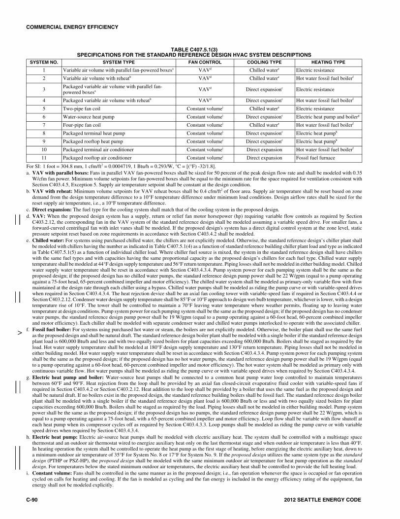
COMMERCIAL ENERGY EFFICIENCY
C-90 2012 SEATTLE ENERGY CODE
TABLE C407.5.1(3) SPECIFICATIONS FOR THE STANDARD REFERENCE DESIGN HVAC SYSTEM DESCRIPTIONS
For SI: 1 foot = 304.8 mm, 1 cfm/ft2 = 0.0004719, 1 Btu/h = 0.293/W, °C = [(°F) -32/1.8]. a. VAV with parallel boxes: Fans in parallel VAV fan-powered boxes shall be sized for 50 percent of the peak design flow rate and shall be modeled with 0.35
W/cfm fan power. Minimum volume setpoints for fan-powered boxes shall be equal to the minimum rate for the space required for ventilation consistent withSection C403.4.5, Exception 5. Supply air temperature setpoint shall be constant at the design condition.
b. VAV with reheat: Minimum volume setpoints for VAV reheat boxes shall be 0.4 cfm/ft2 of floor area. Supply air temperature shall be reset based on zonedemand from the design temperature difference to a 10°F temperature difference under minimum load conditions. Design airflow rates shall be sized for thereset supply air temperature, i.e., a 10°F temperature difference.
c. Direct expansion: The fuel type for the cooling system shall match that of the cooling system in the proposed design. d. VAV: When the proposed design system has a supply, return or relief fan motor horsepower (hp) requiring variable flow controls as required by Section
C403.2.12, the corresponding fan in the VAV system of the standard reference design shall be modeled assuming a variable speed drive. For smaller fans, aforward-curved centrifugal fan with inlet vanes shall be modeled. If the proposed design's system has a direct digital control system at the zone level, staticpressure setpoint reset based on zone requirements in accordance with Section C403.4.2 shall be modeled.
e. Chilled water: For systems using purchased chilled water, the chillers are not explicitly modeled. Otherwise, the standard reference design’s chiller plant shallbe modeled with chillers having the number as indicated in Table C407.5.1(4) as a function of standard reference building chiller plant load and type as indicatedin Table C407.5.1(5) as a function of individual chiller load. Where chiller fuel source is mixed, the system in the standard reference design shall have chillerswith the same fuel types and with capacities having the same proportional capacity as the proposed design’s chillers for each fuel type. Chilled water supplytemperature shall be modeled at 44°F design supply temperature and 56°F return temperature. Piping losses shall not be modeled in either building model. Chilledwater supply water temperature shall be reset in accordance with Section C403.4.3.4. Pump system power for each pumping system shall be the same as theproposed design; if the proposed design has no chilled water pumps, the standard reference design pump power shall be 22 W/gpm (equal to a pump operatingagainst a 75-foot head, 65-percent combined impeller and motor efficiency). The chilled water system shall be modeled as primary-only variable flow with flowmaintained at the design rate through each chiller using a bypass. Chilled water pumps shall be modeled as riding the pump curve or with variable-speed driveswhen required in Section C403.4.3.4. The heat rejection device shall be an axial fan cooling tower with variable-speed fans if required in Section C403.4.4 orSection C403.2.12. Condenser water design supply temperature shall be 85°F or 10°F approach to design wet-bulb temperature, whichever is lower, with a designtemperature rise of 10°F. The tower shall be controlled to maintain a 70°F leaving water temperature where weather permits, floating up to leaving watertemperature at design conditions. Pump system power for each pumping system shall be the same as the proposed design; if the proposed design has no condenserwater pumps, the standard reference design pump power shall be 19 W/gpm (equal to a pump operating against a 60-foot head, 60-percent combined impellerand motor efficiency). Each chiller shall be modeled with separate condenser water and chilled water pumps interlocked to operate with the associated chiller.
f. Fossil fuel boiler: For systems using purchased hot water or steam, the boilers are not explicitly modeled. Otherwise, the boiler plant shall use the same fuelas the proposed design and shall be natural draft. The standard reference design boiler plant shall be modeled with a single boiler if the standard reference designplant load is 600,000 Btu/h and less and with two equally sized boilers for plant capacities exceeding 600,000 Btu/h. Boilers shall be staged as required by theload. Hot water supply temperature shall be modeled at 180°F design supply temperature and 130°F return temperature. Piping losses shall not be modeled ineither building model. Hot water supply water temperature shall be reset in accordance with Section C403.4.3.4. Pump system power for each pumping systemshall be the same as the proposed design; if the proposed design has no hot water pumps, the standard reference design pump power shall be 19 W/gpm (equalto a pump operating against a 60-foot head, 60-percent combined impeller and motor efficiency). The hot water system shall be modeled as primary only withcontinuous variable flow. Hot water pumps shall be modeled as riding the pump curve or with variable speed drives when required by Section C403.4.3.4.
g. Electric heat pump and boiler: Water-source heat pumps shall be connected to a common heat pump water loop controlled to maintain temperaturesbetween 60°F and 90°F. Heat rejection from the loop shall be provided by an axial fan closed-circuit evaporative fluid cooler with variable-speed fans ifrequired in Section C403.4.2 or Section C403.2.12. Heat addition to the loop shall be provided by a boiler that uses the same fuel as the proposed design andshall be natural draft. If no boilers exist in the proposed design, the standard reference building boilers shall be fossil fuel. The standard reference design boilerplant shall be modeled with a single boiler if the standard reference design plant load is 600,000 Btu/h or less and with two equally sized boilers for plantcapacities exceeding 600,000 Btu/h. Boilers shall be staged as required by the load. Piping losses shall not be modeled in either building model. Pump systempower shall be the same as the proposed design; if the proposed design has no pumps, the standard reference design pump power shall be 22 W/gpm, which isequal to a pump operating against a 75-foot head, with a 65-percent combined impeller and motor efficiency. Loop flow shall be variable with flow shutoff ateach heat pump when its compressor cycles off as required by Section C403.4.3.3. Loop pumps shall be modeled as riding the pump curve or with variablespeed drives when required by Section C403.4.3.4.
h. Electric heat pump: Electric air-source heat pumps shall be modeled with electric auxiliary heat. The system shall be controlled with a multistage spacethermostat and an outdoor air thermostat wired to energize auxiliary heat only on the last thermostat stage and when outdoor air temperature is less than 40°F.In heating operation the system shall be controlled to operate the heat pump as the first stage of heating, before energizing the electric auxiliary heat, down toa minimum outdoor air temperature of 35°F for System No. 8 or 17°F for System No. 9. If the proposed design utilizes the same system type as the standarddesign (PTHP or PSZ-HP), the proposed design shall be modeled with the same minimum outdoor air temperature for heat pump operation as the standarddesign. For temperatures below the stated minimum outdoor air temperatures, the electric auxiliary heat shall be controlled to provide the full heating load.
i. Constant volume: Fans shall be controlled in the same manner as in the proposed design; i.e., fan operation whenever the space is occupied or fan operationcycled on calls for heating and cooling. If the fan is modeled as cycling and the fan energy is included in the energy efficiency rating of the equipment, fanenergy shall not be modeled explicitly.
SYSTEM NO. SYSTEM TYPE FAN CONTROL COOLING TYPE HEATING TYPE
1 Variable air volume with parallel fan-powered boxesa VAVd Chilled watere Electric resistance
2 Variable air volume with reheatb VAVd Chilled watere Hot water fossil fuel boilerf
3 Packaged variable air volume with parallel fan-powered boxesa VAVd Direct expansionc Electric resistance
4 Packaged variable air volume with reheatb VAVd Direct expansionc Hot water fossil fuel boilerf
5 Two-pipe fan coil Constant volumei Chilled watere Electric resistance
6 Water-source heat pump Constant volumei Direct expansionc Electric heat pump and boilerg
7 Four-pipe fan coil Constant volumei Chilled watere Hot water fossil fuel boilerf
8 Packaged terminal heat pump Constant volumei Direct expansionc Electric heat pumph
9 Packaged rooftop heat pump Constant volumei Direct expansionc Electric heat pumph
10 Packaged terminal air conditioner Constant volumei Direct expansion Hot water fossil fuel boilerf
11 Packaged rooftop air conditioner Constant volumei Direct expansion Fossil fuel furnace
>
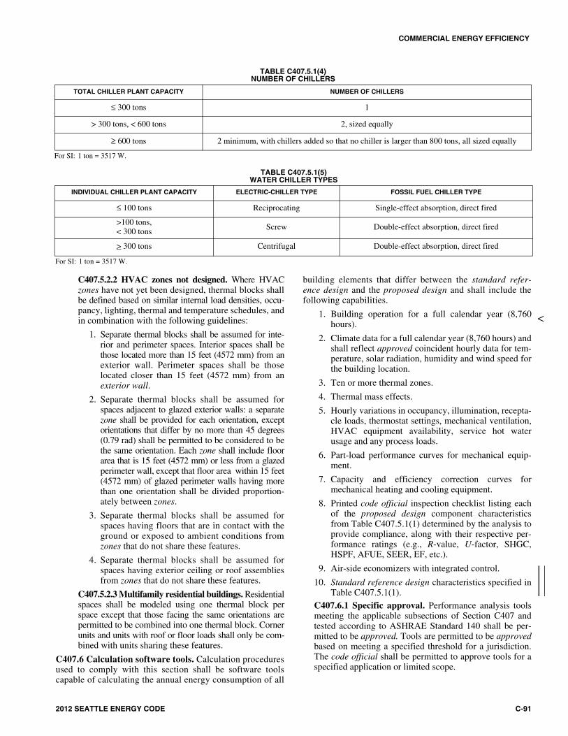
COMMERCIAL ENERGY EFFICIENCY
2012 SEATTLE ENERGY CODE C-91
C407.5.2.2 HVAC zones not designed. Where HVACzones have not yet been designed, thermal blocks shallbe defined based on similar internal load densities, occu-pancy, lighting, thermal and temperature schedules, andin combination with the following guidelines:
1. Separate thermal blocks shall be assumed for inte-rior and perimeter spaces. Interior spaces shall bethose located more than 15 feet (4572 mm) from anexterior wall. Perimeter spaces shall be thoselocated closer than 15 feet (4572 mm) from anexterior wall.
2. Separate thermal blocks shall be assumed forspaces adjacent to glazed exterior walls: a separatezone shall be provided for each orientation, exceptorientations that differ by no more than 45 degrees(0.79 rad) shall be permitted to be considered to bethe same orientation. Each zone shall include floorarea that is 15 feet (4572 mm) or less from a glazedperimeter wall, except that floor area within 15 feet(4572 mm) of glazed perimeter walls having morethan one orientation shall be divided proportion-ately between zones.
3. Separate thermal blocks shall be assumed forspaces having floors that are in contact with theground or exposed to ambient conditions fromzones that do not share these features.
4. Separate thermal blocks shall be assumed forspaces having exterior ceiling or roof assembliesfrom zones that do not share these features.
C407.5.2.3 Multifamily residential buildings. Residentialspaces shall be modeled using one thermal block perspace except that those facing the same orientations arepermitted to be combined into one thermal block. Cornerunits and units with roof or floor loads shall only be com-bined with units sharing these features.
C407.6 Calculation software tools. Calculation proceduresused to comply with this section shall be software toolscapable of calculating the annual energy consumption of all
building elements that differ between the standard refer-ence design and the proposed design and shall include thefollowing capabilities.
1. Building operation for a full calendar year (8,760hours).
2. Climate data for a full calendar year (8,760 hours) andshall reflect approved coincident hourly data for tem-perature, solar radiation, humidity and wind speed forthe building location.
3. Ten or more thermal zones.
4. Thermal mass effects.
5. Hourly variations in occupancy, illumination, recepta-cle loads, thermostat settings, mechanical ventilation,HVAC equipment availability, service hot waterusage and any process loads.
6. Part-load performance curves for mechanical equip-ment.
7. Capacity and efficiency correction curves formechanical heating and cooling equipment.
8. Printed code official inspection checklist listing eachof the proposed design component characteristicsfrom Table C407.5.1(1) determined by the analysis toprovide compliance, along with their respective per-formance ratings (e.g., R-value, U-factor, SHGC,HSPF, AFUE, SEER, EF, etc.).
9. Air-side economizers with integrated control.
10. Standard reference design characteristics specified inTable C407.5.1(1).
C407.6.1 Specific approval. Performance analysis toolsmeeting the applicable subsections of Section C407 andtested according to ASHRAE Standard 140 shall be per-mitted to be approved. Tools are permitted to be approvedbased on meeting a specified threshold for a jurisdiction.The code official shall be permitted to approve tools for aspecified application or limited scope.
>
TABLE C407.5.1(4)NUMBER OF CHILLERS
For SI: 1 ton = 3517 W.
TOTAL CHILLER PLANT CAPACITY NUMBER OF CHILLERS
≤ 300 tons 1
> 300 tons, < 600 tons 2, sized equally
≥ 600 tons 2 minimum, with chillers added so that no chiller is larger than 800 tons, all sized equally
TABLE C407.5.1(5)WATER CHILLER TYPES
For SI: 1 ton = 3517 W.
INDIVIDUAL CHILLER PLANT CAPACITY ELECTRIC-CHILLER TYPE FOSSIL FUEL CHILLER TYPE
≤ 100 tons Reciprocating Single-effect absorption, direct fired
>100 tons, < 300 tons Screw Double-effect absorption, direct fired
> 300 tons Centrifugal Double-effect absorption, direct fired

COMMERCIAL ENERGY EFFICIENCY
C-92 2012 SEATTLE ENERGY CODE
C407.6.2 Input values. Where calculations require inputvalues not specified by Sections C402, C403, C404 andC405, those input values shall be taken from an approvedsource.
C407.6.3 Exceptional calculation methods. When thesimulation program does not model a design, material, ordevice of the proposed design, an exceptional calculationmethod shall be used if approved by the building official.If there are multiple designs, materials, or devices that thesimulation program does not model, each shall be calcu-lated separately and exceptional savings determined foreach. At no time shall the total exceptional savings consti-tute more than half of the difference between the baselinebuilding performance and the proposed building perfor-mance. All applications for approval of an exceptionalmethod shall include:
1. Step-by-step documentation of the exceptional cal-culation method performed detailed enough toreproduce the results;
2. Copies of all spreadsheets used to perform the calcu-lations;
3. A sensitivity analysis of energy consumption wheneach of the input parameters is varied from half todouble the value assumed;
4. The calculations shall be performed on a time stepbasis consistent with the simulation program used;and
5. The performance rating calculated with and withoutthe exceptional calculation method.
SECTION C408 SYSTEM COMMISSIONING
C408.1 General. This section covers the commissioning ofthe building mechanical systems in Section C403, servicewater heating systems in Section C404, electrical power andlighting systems in Section C405 and energy metering inSection C409. Prior to passing the final mechanical andelectrical inspections or obtaining a certificate of occu-pancy, the registered design professional or ((approvedagency)) qualified commissioning authority shall provideevidence of systems commissioning and completion inaccordance with the provisions of this section.
Exception: Where commissioning is not required by Sec-tions C408.2 through C408.5, the requirements of SectionC408.1 do not apply.
Copies of all documentation shall be given to the ownerand made available to the code official upon request in accor-dance with Sections C408.1.2 and C408.1.3.
C408.1.1 Commissioning plan. A commissioning planshall be developed by a registered design professional orqualified commissioning authority and shall include theitems listed in this section. Items 1–4 shall be includedwith the construction documents, and Items 5–8 shall besubmitted prior to the first mechanical inspection. Forprojects where no mechanical inspection is required, Items5–8 shall be submitted prior to the first electrical inspec-
tion. ((A commissioning plan shall be developed by a reg-istered design professional or approved agency and shallinclude the following items:))
1. A narrative description of the activities that will beaccomplished during each phase of commissioning,including the personnel intended to accomplish eachof the activities.
2. Roles and responsibilities of the commissioningteam, including statement of qualifications of thecommissioning authority in accordance with SectionC408.1.
3. A schedule of activities including systems testing andbalancing, functional testing, and supporting docu-mentation.
4. Where the qualified commissioning authority is anemployee of one of the registered design profession-als of record or an employee or subcontractor of theproject contractor, an In-House Commissioning Dis-closure and Conflict Management Plan shall be sub-mitted with the commissioning plan. This Plan shalldisclose the qualified commissioning authority’scontractual relationship with other team membersand provide a conflict management plan demonstrat-ing that the qualified commissioning authority isfree to identify any issues discovered and reportdirectly to the owner.
((4))5. A listing of the specific equipment, appliancesor systems to be tested and a description of the teststo be performed.
((5))6. Functions to be tested.
((6))7. Conditions under which the test will be performed.
((7))8. Measurable criteria for performance.
((C408.1.2 Preliminary commissioning report. A pre-liminary report of commissioning test procedures andresults shall be completed and certified by the registereddesign professional or approved agency and provided tothe building owner. The report shall be identified as “Pre-liminary Commissioning Report” and shall identify:
1. Itemization of deficiencies found during testingrequired by this section that have not been correctedat the time of report preparation.
2. Deferred tests that cannot be performed at the timeof report preparation because of climatic conditions,with anticipated date of completion.
3. Climatic conditions required for performance of thedeferred tests.
4. Record of progress and completion of operator train-ing.))
C408.1.2((.1)) Acceptance of ((report)) Commission-ing Report. Buildings, or portions thereof, shall notpass the final mechanical and electrical inspections orobtain a certificate of occupancy, until such time as thecode official has received a letter of transmittal fromthe building owner acknowledging that the buildingowner has received the ((Preliminary)) CommissioningReport required by Section C408.1.3.4 and the com-
1414141414

COMMERCIAL ENERGY EFFICIENCY
2012 SEATTLE ENERGY CODE C-93
pleted ((.Completion of the)) Commissioning Compli-ance Checklist (Figure C408.1.2.1) ((is deemed tosatisfy this requirement)).
((C408.1.2.2 Copy of report. The code official shall bepermitted to require that a copy of the PreliminaryCommissioning Report be made available for reviewby the code official.))
C408.1.3 Documentation requirements. The constructiondocuments shall specify that the manuals and system bal-ancing report required by Sections C408.1.3.2 andC408.1.3.3 be provided to the building owner prior to issu-ance of the certificate of occupancy, the record documentsrequired by Section C408.1.3.1 ((described in this section))be provided to the building owner within 90 days of the dateof receipt of the certificate of occupancy, and that the Com-missioning Report documents described under SectionC408.1.3.4 be provided to the building owner and the codeofficial prior to issuance of the certificate of occupancy.
C408.1.3.1 Record documents. Construction docu-ments shall be updated to convey a record of the altera-tions to the original design. The updates shall beprovided to the building owner. Such updates shallinclude updated mechanical, electrical and control draw-ings red-lined, or redrawn if specified, that show allchanges to size, type and locations of components,equipment and assemblies.
C408.1.3.2 Manuals. An operating and maintenancemanual shall be provided and include all of the following:
1. Submittal data stating equipment size and selectedoptions for each piece of equipment requiringmaintenance.
2. Manufacturer’s operation manuals and mainte-nance manuals for each piece of equipmentrequiring maintenance, except equipment not fur-nished as part of the project. Required routinemaintenance actions shall be clearly identified.
3. Name and address of at least one service agency.
4. Controls system maintenance and calibrationinformation, including wiring diagrams, schemat-ics, record documents, and control sequencedescriptions. Desired or field-determined set-points shall be permanently recorded on controldrawings at control devices or, for digital controlsystems, in system programming instructions.
5. A narrative of how each system is intended to oper-ate, including recommended setpoints. Sequenceof operation is not acceptable for this requirement.
C408.1.3.3 System balancing report. A written reportdescribing the activities and measurements completedin accordance with Section C408.2.2.
C408.1.3.4 ((Final c))Commissioning report. Areport of test procedures and results identified as“((Final)) Commissioning Report” shall be deliveredto the building owner and code official and shallinclude:
1. Results of functional performance tests.
2. Disposition of deficiencies found during testing,including details of corrective measures used orproposed.
3. Functional performance test procedures used dur-ing the commissioning process including measur-able criteria for test acceptance((, provided hereinfor repeatability)).
4. List and description of any deferred tests whichcannot be completed at the time of report prepa-ration because of climatic conditions, includinganticipated date of completion, climatic condi-tions required for performance of the deferredtests, including timeframe for completion andparties to be involved, in checklist format.
5. List and description of any unresolved deficien-cies or incomplete tasks, in checklist format.
6. A copy of a Commissioning Permit issued for thecompletion and resolution of items identified inthe lists required by Items 4 and 5 above. Thepermit shall stipulate that all such work shall becompleted within one year of issuance of the cer-tificate of occupancy.
Exception: If there are no deferred tests, unre-solved deficiencies or incomplete tasks to belisted under Items 4 and 5, the CommissioningPermit is not required. ((Deferred tests whichcannot be performed at the time of reportpreparation due to climatic conditions.))
7. Completed Commissioning Compliance Check-list (Figure C408.1.2.1).
8. Record of progress and completion of systemsoperation training.
C408.1.4 Systems operation training. Training of themaintenance staff for equipment included in the manualsrequired by Section C408.1.3.2 shall include at a mini-mum:
1. Review of systems documentation.
2. Hands-on demonstration of all normal maintenanceprocedures, normal operating modes, and all emer-gency shutdown and startup procedures.
3. Training completion report.
C408.2 Mechanical systems commissioning and comple-tion requirements. Mechanical equipment and controlsshall comply with Section C408.2.
Construction document notes shall clearly indicate provi-sions for commissioning and completion requirements inaccordance with this section and are permitted to refer tospecifications for further requirements.
Exception: Systems which (a) qualify as simple systemsusing the criteria in Section C403.3, (b) are not required tohave an economizer per Section C403.3.1, and (c) wherethe building total mechanical equipment capacity is lessthan 480,000 Btu/h (140,690 W) cooling capacity and600,000 Btu/h (175,860 W) heating capacity.
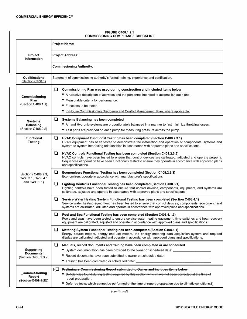
COMMERCIAL ENERGY EFFICIENCY
C-94 2012 SEATTLE ENERGY CODE
FIGURE C408.1.2.1COMMISSIONING COMPLIANCE CHECKLIST
ProjectInformation
Project Name:
Project Address:
Commissioning Authority:
Qualifications(Section C408.1)
Statement of commissioning authority’s formal training, experience and certification.
CommissioningPlan
(Section C408.1.1)
❑ Commissioning Plan was used during construction and included items below
• A narrative description of activities and the personnel intended to accomplish each one.
• Measurable criteria for performance.
• Functions to be tested.
• In-House Commissioning Disclosure and Conflict Management Plan, where applicable.
SystemsBalancing
(Section C408.2.2)
❑ Systems Balancing has been completed
• Air and Hydronic systems are proportionately balanced in a manner to first minimize throttling losses.
• Test ports are provided on each pump for measuring pressure across the pump.
FunctionalTesting
❑ HVAC Equipment Functional Testing has been completed (Section C408.2.3.1)HVAC equipment has been tested to demonstrate the installation and operation of components, systems andsystem-to-system interfacing relationships in accordance with approved plans and specifications.
(Sections C408.2.3,C408.3.1, C408.4.1
and C408.5.1)
❑ HVAC Controls Functional Testing has been completed (Section C408.2.3.2)HVAC controls have been tested to ensure that control devices are calibrated, adjusted and operate properly.Sequences of operation have been functionally tested to ensure they operate in accordance with approved plansand specifications.
❑ Economizers Functional Testing has been completed (Section C408.2.3.3)Economizers operate in accordance with manufacturer's specifications
❑ Lighting Controls Functional Testing has been completed (Section C408.3.1)Lighting controls have been tested to ensure that control devices, components, equipment, and systems arecalibrated, adjusted and operate in accordance with approved plans and specifications.
❑ Service Water Heating System Functional Testing has been completed (Section C408.4.1)Service water heating equipment has been tested to ensure that control devices, components, equipment, andsystems are calibrated, adjusted and operate in accordance with approved plans and specifications.
❑ Pool and Spa Functional Testing has been completed (Section C408.4.1.3)Pools and spas have been tested to ensure service water heating equipment, time switches and heat recoveryequipment are calibrated, adjusted and operate in accordance with approved plans and specifications.
❑ Metering System Functional Testing has been completed (Section C408.5.1)Energy source meters, energy end-use meters, the energy metering data acquisition system and requireddisplay are calibrated, adjusted and operate in accordance with approved plans and specifications.
SupportingDocuments
(Section C408.1.3.2)
❑ Manuals, record documents and training have been completed or are scheduled
• System documentation has been provided to the owner or scheduled date: _____________________
• Record documents have been submitted to owner or scheduled date: _________________________
• Training has been completed or scheduled date: __________________________________________
((CommissioningReport
(Section C408.1.2)))
((❑ Preliminary Commissioning Report submitted to Owner and includes items below
• Deficiencies found during testing required by this section which have not been corrected at the time ofreport preparation.
• Deferred tests, which cannot be performed at the time of report preparation due to climatic conditions.))
(continued)
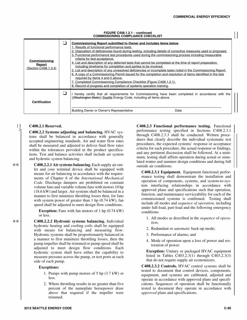
COMMERCIAL ENERGY EFFICIENCY
2012 SEATTLE ENERGY CODE C-95
FIGURE C408.1.2.1—continuedCOMMISSIONING COMPLIANCE CHECKLIST
CommissioningReport
(Section C408.1.3.4)
❑ Commissioning Report submitted to Owner and includes items below1. Results of functional performance tests.2. Disposition of deficiencies found during testing, including details of corrective measures used or proposed.3. Functional performance test procedures used during the commissioning process including measurable criteria for test acceptance.4. List and description of any deferred tests that cannot be completed at the time of report preparation, including timeframe for completion and parties to be involved.5. List and description of any unresolved deficiencies or incomplete tasks noted in the Commissioning Report.6. A copy of a Commissioning Permit issued for the completion and resolution of items identified in the lists required by Items 4 and 5 above.7. Completed Commissioning Compliance Checklist (Figure C408.1.2.1).8. Record of progress and completion of systems operation training.
Certification
❑ I hereby certify that all requirements for Commissioning have been completed in accordance with the((Washington State)) Seattle Energy Code, including all items above.
-------------------------------------------------------------------------------------------------------------------------------------------Building Owner or Owner’s Representative Date
C408.2.1 Reserved.
C408.2.2 Systems adjusting and balancing. HVAC sys-tems shall be balanced in accordance with generallyaccepted engineering standards. Air and water flow ratesshall be measured and adjusted to deliver final flow rateswithin the tolerances provided in the product specifica-tions. Test and balance activities shall include air systemand hydronic system balancing.
C408.2.2.1 Air systems balancing. Each supply air out-let and zone terminal device shall be equipped withmeans for air balancing in accordance with the require-ments of Chapter 6 of the International MechanicalCode. Discharge dampers are prohibited on constantvolume fans and variable volume fans with motors 10 hp(18.6 kW) and larger. Air systems shall be balanced in amanner to first minimize throttling losses then, for fanswith system power of greater than 1 hp (0.74 kW), fanspeed shall be adjusted to meet design flow conditions.
Exception: Fans with fan motors of 1 hp (0.74 kW)or less.
C408.2.2.2 Hydronic systems balancing. Individualhydronic heating and cooling coils shall be equippedwith means for balancing and measuring flow.Hydronic systems shall be proportionately balanced ina manner to first minimize throttling losses, then thepump impeller shall be trimmed or pump speed shall beadjusted to meet design flow conditions. Eachhydronic system shall have either the capability tomeasure pressure across the pump, or test ports at eachside of each pump.
Exceptions:
1. Pumps with pump motors of 5 hp (3.7 kW) orless.
2. Where throttling results in no greater than fivepercent of the nameplate horsepower drawabove that required if the impeller weretrimmed.
C408.2.3 Functional performance testing. Functionalperformance testing specified in Sections C408.2.3.1through C408.2.3.3 shall be conducted. Written proce-dures that clearly describe the individual systematic testprocedures, the expected systems’ response or acceptancecriteria for each procedure, the actual response or findings,and any pertinent discussion shall be followed. At a mini-mum, testing shall affirm operation during actual or simu-lated winter and summer design conditions and during fulloutside air conditions.
C408.2.3.1 Equipment. Equipment functional perfor-mance testing shall demonstrate the installation andoperation of components, systems, and system-to-sys-tem interfacing relationships in accordance withapproved plans and specifications such that operation,function, and maintenance serviceability for each of thecommissioned systems is confirmed. Testing shallinclude all modes and sequence of operation, includingunder full-load, part-load and the following emergencyconditions:
1. All modes as described in the sequence of opera-tion;
2. Redundant or automatic back-up mode;
3. Performance of alarms; and
4. Mode of operation upon a loss of power and res-toration of power.
Exception: Unitary or packaged HVAC equipmentlisted in Tables C403.2.3(1) through C403.2.3(3)that do not require supply air economizers.
C408.2.3.2 Controls. HVAC control systems shall betested to document that control devices, components,equipment, and systems are calibrated, adjusted andoperate in accordance with approved plans and specifi-cations. Sequences of operation shall be functionallytested to document they operate in accordance withapproved plans and specifications.
>
**
**
COMMERCIAL ENERGY EFFICIENCY
C-96 2012 SEATTLE ENERGY CODE
C408.2.3.3 Economizers. Air economizers shallundergo a functional test to determine that they operatein accordance with manufacturer’s specifications.
C408.3 Lighting system functional testing. Controls forautomatic lighting systems shall comply with SectionC408.3.1.
Exception: Lighting systems are exempt from the func-tional testing requirements in buildings where the totalinstalled lighting load is less than 20 kW and less than 10kW of lighting load is controlled by occupancy sensors orautomatic daylighting controls.
C408.3.1 Functional testing. Testing shall ensure thatcontrol hardware and software are calibrated, adjusted, pro-grammed and in proper working condition in accordancewith the construction documents and manufacturer’s instal-lation instructions. Written procedures that clearly describethe individual systematic test procedures, the expected sys-tems’ response or acceptance criteria for each procedure,the actual response or findings, and any pertinent discus-sion shall be followed. At a minimum, testing shall affirmoperation during normally occupied daylight conditions.The construction documents shall state the party who willconduct the required functional testing.
Where occupant sensors, time switches, programmableschedule controls, photosensors or daylighting controls areinstalled, the following procedures shall be performed:
1. Confirm that the placement, sensitivity and time-outadjustments for occupant sensors yield acceptableperformance.
2. Confirm that the time switches and programmableschedule controls are programmed to turn the lightsoff.
3. Confirm that the placement and sensitivity adjust-ments for photosensor controls reduce electric lightbased on the amount of usable daylight in the spaceas specified.
C408.4 Service water heating systems commissioningand completion requirements. Service water heatingequipment and controls shall comply with Section C408.4.Construction document notes shall clearly indicate provi-sions for commissioning and completion requirements inaccordance with this section and are permitted to refer tospecifications for further requirements.
Exception: The following systems are exempt from thecommissioning requirements:
1. Service water heating systems in buildings wherethe largest service water heating system capacity isless than 200,000 Btu/h (58 562 W) and where thereare no pools or in-ground permanently installedspas.
C408.4.1 Functional performance testing. Functionalperformance testing specified in Sections C408.4.1.1through C408.4.1.3 shall be conducted. Written proce-dures that clearly describe the individual systematic testprocedures, the expected systems’ response or acceptancecriteria for each procedure, the actual response or findings,and any pertinent discussion shall be followed. At a mini-
mum, testing shall affirm operation with the system under50 percent water heating load.
C408.4.1.1 Equipment. Equipment functional perfor-mance testing shall demonstrate the installation andoperation of components, systems, and system-to-sys-tem interfacing relationships in accordance withapproved plans and specifications such that operation,function, and maintenance serviceability for each of thecommissioned systems is confirmed. Testing shallinclude all modes and sequence of operation, includingunder full-load, part-load and the following emergencyconditions:
1. Redundant or automatic backup mode;
2. Performance of alarms; and
3. Mode of operation upon a loss of power and res-toration of power.
C408.4.1.2 Controls. Service water heating controlsshall be tested to document that control devices, com-ponents, equipment, and systems are calibrated,adjusted and operate in accordance with approved plansand specifications. Sequences of operation shall befunctionally tested to document they operate in accor-dance with approved plans and specifications.
C408.4.1.3 Pools and spas. Service water heatingequipment, time switches, and heat recovery equipmentwhich serve pools and in-ground permanently installedspas shall undergo a functional test to determine thatthey operate in accordance with manufacturer’s specifi-cations.
C408.5 Metering system commissioning. Energy meteringsystems required by Section C409 shall comply with Sec-tion C408.5 and be included in the commissioning processrequired by Section C408.1. Construction documents shallclearly indicate provisions for commissioning in accordancewith Section C408 and are permitted to refer to specifica-tions for further requirements.
C408.5.1 Functional testing. Functional testing shall beconducted by following written procedures that clearlydescribe the individual systematic test procedures, theexpected systems’ response or acceptance criteria for eachprocedure, the actual response or findings, and any perti-nent discussion. Functional testing shall document thatenergy source meters, energy end-use meters, the energymetering data acquisition system, and required energyconsumption display are calibrated, adjusted and operatein accordance with approved plans and specifications. At aminimum, testing shall confirm that:
1. The metering system devices and components workproperly under low and high load conditions.
2. The metered data is delivered in a format that iscompatible with the data collection system.
3. The energy display is accessible to building opera-tion and management personnel.
4. The energy display meets code requirements regard-ing views required in Section C409.4.3. The displayshows energy data in identical units (e.g., kWh).
>

COMMERCIAL ENERGY EFFICIENCY
2012 SEATTLE ENERGY CODE C-97
SECTION C409ENERGY METERING AND
ENERGY CONSUMPTION MANAGEMENT
C409.1 General. Buildings with a gross conditioned floorarea over ((50,000)) 20,000 square feet (((4645)) 1860 m2)shall comply with Section C409. Buildings shall beequipped to measure, monitor, record and display energyconsumption data for each energy source and end use cate-gory per the provisions of this section, to enable effectiveenergy management. For Group R-2 multifamily buildings,the floor area of dwelling units shall be excluded from thetotal conditioned floor area. Alterations and additions toexisting buildings shall conform to Section C409.5.
Exceptions:
1. Tenant spaces within buildings if the tenant spacehas its own utility service and utility meters.
2. Buildings in which there is no gross conditionedfloor area over ((25,000)) 10,000 square feet(((2323)) 929 m2), including building common area,that is served by its own utility services and meters.
C409.1.1 Alternate metering methods. Where approvedby the building official, energy use metering systems maydiffer from those required by this section, provided thatthey are permanently installed and that the source energymeasurement, end use category energy measurement, datastorage and data display have similar accuracy to and areat least as effective in communicating actionable energyuse information to the building management and users, asthose required by this section.
C409.1.2 Conversion factor. Any threshold stated in kWor kVA shall include the equivalent Btu/h heating andcooling capacity of installed equipment at a conversionfactor of 3,412 Btu per kW or 2,730 Btu per kVA ((at 50percent demand)).
C409.2 Energy source metering. Buildings shall have ameter at each energy source. For each energy supply sourcelisted in Sections C409.2.1 through C409.2.4, meters shallcollect data for the whole building or for each separatelymetered portion of the building where not exempted by theexceptions to Section C409.1.
Exceptions:
1. Energy source metering is not required where enduse metering for an energy source accounts for allusage of that energy type within a building, and thedata acquisition system accurately totals the energydelivered to the building or separately metered por-tion of the building.
2. Solid fuels such as coal, firewood or wood pelletsthat are delivered via mobile transportation do notrequire metering.
C409.2.1 Electrical energy. This category shall includeall electrical energy supplied to the building and its associ-ated site, including site lighting, parking, recreationalfacilities, and other areas that serve the building and itsoccupants.
Exception: Where site lighting and other exterior non-building electrical loads are served by an electrical ser-vice and meter that are separate from the building ser-vice and meter, the metering data from those loads ispermitted to be either combined with the building’selectrical service load data or delivered to a separatedata acquisition system.
C409.2.2 Gas and liquid fuel supply energy. This cate-gory shall include all natural gas, fuel oil, propane and othergas or liquid fuel energy supplied to the building and site.
C409.2.3 District energy. This category shall include allnet energy extracted from district steam systems, districtchilled water loops, district hot water systems, or otherenergy sources serving multiple buildings.
C409.2.4 Site-generated renewable energy. This cate-gory shall include all net energy generated from on-sitesolar, wind, geothermal, tidal or other natural sources, andwaste heat reclaimed from sewers or other off-site sources.
C409.3 End-use metering. Meters shall be provided to col-lect energy use data for each end-use category listed in Sec-tions C409.3.1 through ((C409.3.2)) C409.3.6. These metersshall collect data for the whole building or for each sepa-rately metered portion of the building where not exemptedby the exceptions to Section C409.1. Not more than 10 per-cent of the total connected load of any of the end-use meter-ing categories in Sections C409.3.1 through C409.3.5 ispermitted to be excluded from that end-use data collection.Not more than 10 percent of the total connected load of anyof the end-use metering categories in Sections C409.3.1through C409.3.5 is permitted to consist of loads not part ofthat category. Multiple meters may be used for any end-usecategory, provided that the data acquisition system totals allof the energy used by that category. Full-floor tenant spacesub-metering data shall be provided to the tenant in accor-dance with Section C409.3.5, and the data shall not berequired to be included in other end-use categories.
Exceptions:
1. HVAC and water heating equipment serving only anindividual dwelling unit does not require end-usemetering.
2. Separate metering is not required for fire pumps,stairwell pressurization fans or other life safety sys-tems that operate only during testing or emergency.
3. End use metering is not required for individual ten-ant spaces not exceeding 2,500 square feet (232 m2)in floor area when a dedicated source meter meetingthe requirements of Section C409.4.1 is provided forthe tenant space.
4. Healthcare facilities with loads in excess of 150kVA are permitted to have sub-metering that mea-sures electrical energy usage in accordance with thenormal and essential electrical systems identified inArticle 517 of the Seattle Electrical Code, exceptthat sub-metering is required for the following loadcategories:
4.1. HVAC system energy use per the require-ments of Section C409.3.1.

COMMERCIAL ENERGY EFFICIENCY
C-98 2012 SEATTLE ENERGY CODE
4.2. Water heating energy use per the require-ments of Section C409.3.2.
4.3. Process load system energy per the require-ments of Section C409.3.5 for each signifi-cant facility not used in direct patient care,including but not limited to food service,laundry and sterile processing facilities,where the total connected load of that facil-ity exceeds 100 kVA.
5. End-use metering is not required for electrical cir-cuits serving only sleeping rooms and guest suiteswithin R-1 occupancies. This exception does notapply to common areas or to equipment servingmultiple sleeping rooms.
C409.3.1 HVAC system energy use. This category shallinclude all energy including electrical, gas, liquid fuel, dis-trict steam and district chilled water that is used by boilers,chillers, pumps, fans and other equipment used to providespace heating, space cooling, dehumidification and venti-lation to the building, but not including energy that servesprocess loads, water heating or miscellaneous loads asdefined in Section C409.3. Multiple HVAC energysources, such as gas, electric and steam, are not required tobe summed together.
Exceptions:
1. All 120 volt equipment.
2. 208/120 volt equipment in a building where themain service is 480/277 volt power.
3. Electrical energy fed through variable frequencydrives that are connected to the energy meteringdata acquisition center.
C409.3.2 Water heating energy use. This category shallinclude all energy used for heating of domestic and servicehot water, but not energy used for space heating.
Exception: Water heating energy use less than 50((kW)) kVA does not require end-use metering.
C409.3.3 Lighting system energy use. This categoryshall include all energy used by interior and exterior light-ing, including lighting in parking structures and lots, butnot including plug-in task lighting.
C409.3.4 Plug load system energy use. This categoryshall include all energy used by appliances, computers,plugged-in task lighting, and other equipment and devices,but not including vertical transportation equipment orequipment covered by other end-use metering categorieslisted in Section C409.3. In a building where the main ser-vice is 480/277 volt, each 208/120 volt panel is permittedto be assumed to serve only plug load for the purpose ofSection C409, unless it serves nonresidential refrigerationor cooking equipment.
Exception: Where the total connected load of all plugload circuits is less than 50 kVA, end-use metering isnot required.
C409.3.5 Process load system energy use. Meters shallcollect data for energy used by any nonbuilding processload, including but not limited to nonresidential refrigera-
tion and cooking equipment, laundry equipment, industrialequipment and stage lighting.
Exception: Process load energy use less than 50 kVAdoes not require end-use metering.
C409.3.6 Full-floor tenant space electrical sub-meter-ing. In a multitenant building, where more than 90 percentof the leasable area of a floor is occupied by a single ten-ant, an electrical energy use display shall be provided tothe tenant in accordance with the requirements of SectionC409.4.3. Electrical loads from areas outside of the tenantspace or from equipment that serves areas outside of thetenant space shall not be included in the tenant space sub-metering. A single display is permitted to serve multiplefloors occupied by the same tenant.
C409.4 Measurement devices, data acquisition systemand energy display.
C409.4.1 Meters. Meters and other measurement devicesrequired by this section shall have local displays or beconfigured to automatically communicate energy data to adata acquisition system. Source meters may be any digital-type meters. Current sensors or flow meters are allowedfor end-use metering, provided that they have an accuracyof +/- 5 percent. All required metering systems and equip-ment shall provide at least hourly data that is fully inte-grated into the data acquisition and display system per therequirements of Section C409.
C409.4.2 Data acquisition system. The data acquisitionsystem shall store the data from the required meters andother sensing devices for a minimum of 36 months. Foreach energy supply and end-use category required by Sec-tions C409.2 and C409.3, it shall provide real-time energyconsumption data and logged data for any hour, day,month or year.
C409.4.3 Energy display. For each building subject toSections C409.2 and C409.3, either a readily accessibleand visible display, or a web page or other electronic doc-ument accessible to building management or to a third-party energy data analysis service shall be provided in thebuilding accessible by building operation and managementpersonnel. The display shall graphically provide the cur-rent energy consumption rate for each whole buildingenergy source, plus each end-use category, as well as theaverage and peak values for any day, week or year.
C409.4.4 Commissioning. The entire system shall becommissioned in accordance with Section C408.5. Defi-ciencies found during testing shall be corrected andretested and the commissioning report shall be updated toconfirm that the entire metering and data acquisition anddisplay system is fully functional.
C409.5 Metering for existing buildings.
C409.5.1 Existing buildings that were constructed sub-ject to the requirements of this section. Where new orreplacement systems or equipment are installed in anexisting building that was constructed subject to therequirements of this section, metering shall be providedfor such new or replacement systems or equipment so thattheir energy use is included in the corresponding end-use

COMMERCIAL ENERGY EFFICIENCY
2012 SEATTLE ENERGY CODE C-99
category defined in Section C409.2. This includes systemsor equipment added in conjunction with additions or alter-ations to existing buildings.
C409.5.1.1 Small existing buildings. For existingbuildings that were constructed subject to the require-ments of this code, but were exempt from the require-ments of Section C409 due to being smaller than thethresholds set forth in Section C409.1, ((M))meteringand data acquisition systems shall be provided for addi-tions over ((25,000)) 10,000 square feet (((2323)) 929m2) in accordance with the requirements of SectionsC409.2, ((and)) C409.3 and C409.4.
C409.5.2 Metering for HVAC equipment replacement.Where permits are issued for new or replacement HVACequipment that has a total heating and cooling capacitygreater than 1,200 kBtu/hour and greater than 50 percentof the building’s existing HVAC heating and coolingcapacity, within any 12-month period, the following shallbe provided for the building:
1. Energy source metering required by Section C409.2.
2. HVAC system end-use metering required by SectionC409.3.1.
3. Data acquisition and display system per the require-ments of Section C409.4.
Each of the building’s existing HVAC chillers, boilers,cooling towers, air handlers, packaged units and heatpumps that has a capacity larger than 5 tons or that repre-sents more than 10 percent of the total heating and coolingcapacity of the building shall be included in the calculationof the existing heating and cooling capacity of the build-ing. Where heat pumps are configured to deliver bothheating and cooling, the heating and cooling capacitiesshall both be included in the calculation of the total capac-ity.
Each of the building’s existing and new HVAC chillers,boilers, cooling towers, air handlers, packaged units andheat pumps that has a heating or cooling capacity largerthan 5 tons or that represents more than 10 percent of thetotal heating and cooling capacity of the building shall beincluded in the HVAC system end-use metering.
Construction documents for new or replacement heat-ing and cooling equipment projects shall indicate the totalheating and cooling capacity of the building’s existingHVAC equipment and the total heating and cooling capac-ity of the new or replacement equipment. Where permitshave been issued for new or replacement heating and cool-ing equipment within the 12-month period prior to the per-mit application date, the heating and cooling capacity ofthat equipment shall also be indicated. For the purpose ofthis tabulation, heating and cooling capacities of all equip-ment shall be expressed in kBtu/hour.
C409.5.3 Tenant space electrical sub-metering forexisting buildings. For tenant improvements in which asingle tenant will occupy a full floor of a building, theelectrical consumption for the tenant space on that floorshall be separately metered, and the metering data pro-vided to the tenant with a display system per the require-
ments of Section C409.4.3. For the purposes of thissection, separate end-use categories need not be segre-gated.
Exception: Where an existing branch circuit electricalpanel serves tenant spaces on multiple full floors of abuilding, the floors served by that panel are notrequired to comply with this section.
C409.5.4 Metering for complete electrical systemreplacement. If all, or substantially all, of the existingelectrical system is replaced under a single electrical per-mit or within a 12-month period, all of the provisions ofSection C409 shall be met.
SECTION C410RENEWABLE ENERGY AND SOLAR READINESS
C410.1 On-site renewable energy systems. Each new build-ing or addition larger than 5,000 square feet (465 m2) of grossconditioned floor area shall include a renewable energy gen-eration system consisting of at least 70 Watts rated peak PV(photovoltaic) energy production, or 240 kBtu of annualSWH (solar water heating) energy production, per 1,000square feet (92.9 m2) of conditioned space or fraction thereof.For buildings over five stories in height, the conditioned areafor this calculation shall be based on the conditioned area ofthe largest five above-grade stories in the building. This sys-tem is permitted to be mounted either within the allocatedsolar zone required by Section C410.2.3, or elsewhere on thebuilding or site.
Exceptions:
1. Higher-efficiency mechanical equipment is permit-ted to be provided in lieu of on-site renewableenergy systems, where the capacity-weightedequipment efficiency for the total capacity of thespace heating and space cooling equipment is aminimum of 1.10 times the corresponding mini-mum efficiency in Tables C403.2.3(1) throughC403.2.3(8). The minimum efficiency for thisexception shall be in excess of that required else-where in the Seattle Energy Code, including Sec-tion C403.4.1 (economizers). The StandardReference Design determination from SectionC407 shall be used to establish the baseline casefor determination of the 1.10 factor.
2. Additional heat recovery systems beyond thoserequired by this code are permitted to be provided inlieu of on-site renewable energy systems, where thecalculated net annual energy savings from the heatrecovery systems exceed the calculated net annualenergy production of the required on-site renewableenergy systems. Acceptable heat recovery systemsinclude but are not limited to: exhaust air heat recov-ery in excess of that required by this code, wastewater or sewer heat recovery, ground source heatingand cooling, or heat recovered from other on-site oroff-site sources that would otherwise be lost into thesewer or atmosphere.

COMMERCIAL ENERGY EFFICIENCY
C-100 2012 SEATTLE ENERGY CODE
C410.2 Solar readiness.
C410.2.1 General. In addition to the requirements of Sec-tion C410.1, a solar zone shall be provided on nonresiden-tial buildings of any size that are five stories or less inheight above grade plane, and shall be located on the roofof the building or on another structure elsewhere on thesite. The solar zone shall be in accordance with SectionsC410.2.2 through C410.2.8 and the International FireCode.
Exception: A solar zone is not required where the solarexposure of the building’s roof area is less than 75 per-cent of that of an unobstructed area, as defined in Sec-tion C410.2.3, in the same location, as measured by oneof the following:
1. Incident solar radiation expressed in kWh/ft2-yrusing typical meteorological year (TMY) data;
2. Annual sunlight exposure expressed in cumula-tive hours per year using TMY data;
3. Shadow studies indicating that the roof area ismore than 25 percent in shadow, on September21 at 10 am, 11 am, 12 pm, 1 pm, and 2 pm solartime.
C410.2.2 Minimum area. The minimum area of the solarzone shall be determined by one of the following methods,whichever results in the smaller area:
1. 40 percent of roof area. The roof area shall be calcu-lated as the horizontally-projected gross roof arealess the area covered by skylights, occupied roofdecks and planted areas.
2. 20 percent of electrical service size. The electricalservice size shall be the rated capacity of the total ofall electrical services to the building, and therequired solar zone size shall be based upon 10 peakwatts of PV per square foot.
Exception: Subject to the approval of the code official,buildings with extensive rooftop equipment that wouldmake full compliance with this section impractical shallbe permitted to reduce the size of the solar zonerequired by Section C410.2.2 to the maximum practica-ble area.
C410.2.3 Obstructions. The solar zone shall be free ofpipes, vents, ducts, HVAC equipment, skylights and otherobstructions, except those serving PV or SWH systemswithin the solar zone. PV or SHW systems are permittedto be installed within the solar zone. The solar zone is per-
mitted to be located above any such obstructions, providedthat the racking for support of the future system isinstalled at the time of construction, the elevated solarzone does not shade other portions of the solar zone, andits height is permitted by the International Building Codeand Seattle Land Use Code.
C410.2.4 Shading. The solar zone shall be set back fromany existing or new object on the building or site that islocated south, east, or west of the solar zone a distance atleast two times the object’s height above the nearest pointon the roof surface. Such objects include but are not lim-ited to taller portions of the building itself, parapets, chim-neys, antennas, signage, rooftop equipment, trees and roofplantings. No portion of the solar zone shall be located ona roof slope greater than 2:12 that faces within 45 degreesof true north.
C410.2.5 Contiguous area. The solar zone is permitted tobe comprised of smaller separated sub-zones. Each sub-zone shall be at least 5 feet (1524 mm) wide in the narrow-est dimension.
C410.2.6 Access. Areas contiguous to the solar zone shallprovide access pathways and provisions for emergencysmoke ventilation as required by the International FireCode.
C410.2.7 Structural integrity. If the solar zone is on theroof of the building or another structure on the site, the as-designed dead load and live load for the solar zone shallbe clearly marked on the record drawings, and shallaccommodate future PV or SHW arrays at an assumeddead load of 5 pounds per square foot in addition to otherrequired live and dead loads. For PV systems, a locationfor future inverters shall be designated either within oradjacent to the solar zone, with a minimum area of 2square feet (0.186 m2) for each 1,000 square feet (92.9 m2)of solar zone area, and shall accommodate an assumeddead load of 175 pounds per square foot. Where PV orSWH systems are installed in the solar zone, structuralanalysis shall be based upon calculated loads, not uponthese assumed loads.
C410.2.8 PV or SWH interconnection provisions.Buildings shall provide for the future interconnection ofeither a PV system in accordance with Section C410.2.8.1or an SWH system in accordance with Section C410.2.8.2.
C410.2.8.1 PV interconnection. A capped roof pene-tration sleeve shall be provided in the vicinity of thefuture inverter, sized to accommodate the future PVsystem conduit. Interconnection of the future PV sys-tem shall be provided for at the main service panel,either ahead of the service disconnecting means or atthe end of the bus opposite the service disconnectingmeans, in one of the following forms:
1. A space for the mounting of a future overcurrentdevice, sized to accommodate the largest stan-dard rated overcurrent device that is less than 20percent of the bus rating.
2. Lugs sized to accommodate conductors with anampacity of at least 20 percent of the bus rating,
Example: A building with a 10,000 ft2 total roof area,1,000 ft2 skylight area, and a 400 amp, 240 volt singlephase electrical service is required to provide a solar zonearea of the smaller of the following:
1. [40% x (10,000 ft2 roof area – 1,000 ft2 skylights)] = 3,600 ft2; or 2. [400 amp x 240 volts x 20% / 10 watts per ft2] = 1,920 ft2
Therefore, a solar zone of 1,920 square feet is required.

COMMERCIAL ENERGY EFFICIENCY
2012 SEATTLE ENERGY CODE C-101
to enable the mounting of an external overcurrentdevice for interconnection.
The electrical construction documents shall indicatethe following:
1. Solar zone boundaries and access pathways;
2. Location for future inverters and metering equip-ment; and
3. Route for future wiring between the PV panelsand the inverter, and between the inverter and themain service panel.
C410.2.8.2 SWH interconnection. Two capped pipetees shall be provided upstream of the domestic waterheating equipment to provide plumbing interconnec-tions between a future SWH system and the domesticwater heating system. Two roof penetration sleevesshall be provided in the vicinity of the solar zone, capa-ble of accommodating supply and return piping for afuture SWH system.
The plumbing construction documents shall indicatethe following:
1. Solar zone boundaries and access pathways;
2. Location for future hot water storage tanks; and
3. Route for future piping between the solar zoneand the plumbing interconnection point, follow-ing the shortest feasible pathway.

C-102 2012 SEATTLE ENERGY CODE