
COMMANDER 300 Operating Guide Process Controller ... · To prevent false triggering ... twin...
24
ABB Automation Operating Guide MODBUS (RTU) Communications Option COMMANDER 300 Universal Process Controller COMMANDER 300 50.0 47.5 PV SP A1 A2 L R ST M
Transcript of COMMANDER 300 Operating Guide Process Controller ... · To prevent false triggering ... twin...

ABB Automation
Operating Guide
MODBUS (RTU)Communications Option
COMMANDER 300UniversalProcess Controller
COMMANDER 300
50.047.5
PV
SP
A1 A2 L R ST M
ABB INSTRUMENTATION
BS EN ISO 9001
St Neots, U.K. – Cert. No. Q5907Stonehouse, U.K. – Cert. No. FM 21106
The CompanyABB Instrumentation is an established world force in the design andmanufacture of instrumentation for industrial process control, flowmeasurement, gas and liquid analysis and environmentalapplications.
As a part of ABB, a world leader in process automation technology,we offer customers application expertise, service and supportworldwide.
We are committed to teamwork, high quality manufacturing,advanced technology and unrivalled service and support.
The quality, accuracy and performance of the Company’s productsresult from over 100 years experience, combined with a continuousprogram of innovative design and development to incorporate thelatest technology.
The NAMAS Calibration Laboratory No. 0255 is just one of the tenflow calibration plants operated by the Company, and is indicative ofABB Instrumentation's dedication to quality and accuracy.
Health and SafetyTo ensure that our products are safe and without risk to health, the following points must be noted:
1. The relevant sections of these instructions must be read carefully before proceeding.
2. Warning labels on containers and packages must be observed.
3. Installation, operation, maintenance and servicing must only be carried out by suitably trained personnel andin accordance with the information given.
4. Normal safety precautions must be taken to avoid the possibility of an accident occurring when operating inconditions of high pressure and/or temperature.
5. Chemicals must be stored away from heat, protected from temperature extremes and powders kept dry.Normal safe handling procedures must be used.
6. When disposing of chemicals ensure that no two chemicals are mixed.
Safety advice concerning the use of the equipment described in this manual or any relevant hazard data sheets(where applicable) may be obtained from the Company address on the back cover, together with servicing andspares information.
Note.Clarification of an instruction or additionalinformation.
Information.Further reference for more detailed information ortechnical details.
Although Warning hazards are related to personal injury, and Caution hazards are associated with equipment orproperty damage, it must be understood that operation of damaged equipment could, under certain operationalconditions, result in degraded process system performance leading to personal injury or death. Therefore, complyfully with all Warning and Caution notices.
Information in this manual is intended only to assist our customers in the efficient operation of our equipment. Useof this manual for any other purpose is specifically prohibited and its contents are not to be reproduced in full orpart without prior approval of Technical Communications Department, ABB Instrumentation.
EN 29001 (ISO 9001)
Lenno, Italy – Cert. No. 9/90A
Use of Instructions
Warning.An instruction that draws attention to the risk ofinjury or death.
Caution.An instruction that draws attention to the risk ofdamage to the product, process or surroundings.
Stonehouse, U.K.
0255
Licensing, Trademarks and CopyrightsModbus™ is a trademark of Modicon, Inc.IBM™ and IBM PC AT™ are trademarks of International Business Machines Corp.
ISO 9001
REGISTERE
D

1
CONTENTS
Section Page Section Page1 INTRODUCTION .................................. 2
2 ELECTRICAL INSTALLATION ............ 22.1 Selection of Serial
Communication Adaptors forPersonal Computers .................... 2
2.2 RecommendedOPTO22 Boards .......................... 3
2.3 Pull-up and Pull-downResistors ...................................... 3
2.4 Termination Resistors .................. 42.5 RS485/422 Standard ................... 42.6 Serial Connections ....................... 5
3 PROGRAMMING .................................. 63.1 Serial Data Communication
Page .......................................... 7
4 MODBUS PROTOCOL ......................... 84.1 Introduction to Modbus
Protocol ........................................ 84.1.1 Non-volatile Memory
Limitations ........................ 84.2 Modbus Function Codes .............. 9
5 MODBUS FUNCTIONS ...................... 105.1 Read Coil Status –
Function Code 01 ....................... 105.1.1 Read Coil Status Query .. 105.1.2 Read Coil Status
Response ....................... 105.2 Read Holding Register –
Function Code 03 ....................... 115.2.1 Read Holding
Register Query ............... 115.2.2 Read Holding
Register Response ......... 115.3 Force Single Coil –
Function Code 05 ....................... 125.3.1 Force Single Coil
Query .............................. 125.3.2 Force Single Coil
Response ....................... 125.4 Preset Single Register –
Function Code 06 ....................... 135.4.1 Preset Single Register
Query .............................. 135.4.2 Preset Single Register
Response ....................... 135.5 Loopback Test –
Function Code 08 ....................... 145.5.1 Loopback Test
Query .............................. 145.5.2 Loopback Test
Response ....................... 145.6 Write Multiple Registers –
Function Code 16 ....................... 155.6.1 Write Multiple Registers
Query .............................. 155.6.2 Write Multiple Registers
Response ....................... 15
6 EXCEPTION RESPONCES ................ 166.1 Examples ................................... 16
7 MODBUS REGISTERS ...................... 177.1 Coils ........................................ 177.2 Holding Registers ....................... 187.3 Controller Settings/Outputs ........ 197.4 Alarm Settings ............................ 207.5 Ramp/Soak Settings .................. 20
2
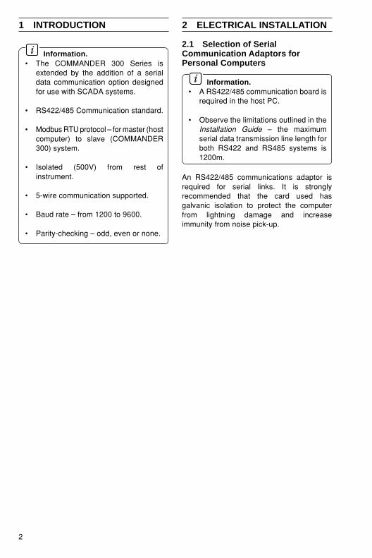
1 INTRODUCTION
Information.• The COMMANDER 300 Series is
extended by the addition of a serialdata communication option designedfor use with SCADA systems.
• RS422/485 Communication standard.
• Modbus RTU protocol – for master (hostcomputer) to slave (COMMANDER300) system.
• Isolated (500V) from rest ofinstrument.
• 5-wire communication supported.
• Baud rate – from 1200 to 9600.
• Parity-checking – odd, even or none.
2.1 Selection of SerialCommunication Adaptors forPersonal Computers
Information.• A RS422/485 communication board is
required in the host PC.
• Observe the limitations outlined in theInstallation Guide – the maximumserial data transmission line length forboth RS422 and RS485 systems is1200m.
An RS422/485 communications adaptor isrequired for serial links. It is stronglyrecommended that the card used hasgalvanic isolation to protect the computerfrom lightning damage and increaseimmunity from noise pick-up.
2 ELECTRICAL INSTALLATION

3
2 ELECTRICAL INSTALLATION…
2.2 Recommended OPTO22 BoardsThe following OPTO22 boards are recommended for use with the COMMANDER 300 Series ofinstruments:
Part No. Computer TypeAC24 AT AT Bus IBM PC compatibleAC34 Microchannel IBM PC
2.3 Pull-up and Pull-down Resistors – Fig. 2.1To prevent false triggering of the slave (COMMANDER 300) by the presence of noise when themaster (host computer) is inactive, 1.8K pull-up and pull-down resistors must be fitted to theRS422/485 adaptor card – see Fig. 2.1.
Fig. 2.1 Pull-up and Pull-down Resistors
89101112
GND
Rx+
Rx–
Tx+
Tx–
A BC
C
COMMANDER 300
Computer Terminal or Host Computer
+5V
0V
'A'
'B'
1.8kΩPull-downResistor
1.8kΩPull-upResistor
0V
+5V
0V
'A'
'B'
1.8kΩPull-downResistor
1.8kΩPull-upResistor

4
…2 ELECTRICAL INSTALLATION
2.4 Termination Resistors – Fig. 2.2For long transmission lines, termination resistors are required on the last slave in the chain –see Fig. 2.2A. The slave termination resistors are selected using plug-in links (PL1) on theserial board – see Fig. 2.2B.
2.5 RS485/422 StandardThe RS485 standard quotes connection of thirty two slaves maximum, to any single driver(computer terminal or host computer); the RS422 standard quotes connection of up to tenslaves. However, these numbers can be increased if the driver’s serial port permits.
Fig. 2.2 Selecting the Slave Termination Resistor
A – Schematic Diagram
B – Termination Resistor Link Positions
PL1
PL1
Internal Termination Resistor
IdentifyLinks
1 8
4 5
1 8
4 5
1 8
4 5
TerminationResistorsLinked-out
InvertController
Position links
TerminationResistorsLinked-in
PL1
1
2
3
5
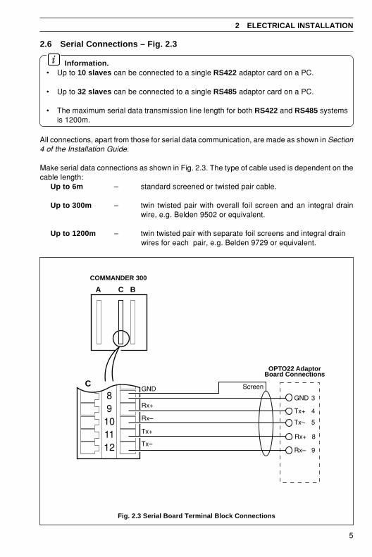
2.6 Serial Connections – Fig. 2.3
Information.• Up to 10 slaves can be connected to a single RS422 adaptor card on a PC.
• Up to 32 slaves can be connected to a single RS485 adaptor card on a PC.
• The maximum serial data transmission line length for both RS422 and RS485 systemsis 1200m.
All connections, apart from those for serial data communication, are made as shown in Section4 of the Installation Guide.
Make serial data connections as shown in Fig. 2.3. The type of cable used is dependent on thecable length:
Up to 6m – standard screened or twisted pair cable.
Up to 300m – twin twisted pair with overall foil screen and an integral drainwire, e.g. Belden 9502 or equivalent.
Up to 1200m – twin twisted pair with separate foil screens and integral drain wires for each pair, e.g. Belden 9729 or equivalent.
2 ELECTRICAL INSTALLATION
Fig. 2.3 Serial Board Terminal Block Connections
Rx+
Rx–
Tx–
Tx+
GND
8
9
5
4
3
OPTO22 AdaptorBoard Connections
Screen
89101112
GND
Rx+
Rx–
Tx+
Tx–
A BC
C
COMMANDER 300

6 3P
RO
GR
AM
MIN
G
Fig
. 3.1 Lo
cation
of S
erial Data (R
S485) C
om
mu
nicatio
ns P
age
SErIAL
BAUd9600
IdEnt1
PArItYodd
PAGE
SCALE
AdJUSt
LINE
FAILEd
ACKNLG
ALArMS
SECOdE
0
SELF
tUNE
ContrL
PAGE
PrOFLE
PrOGM
SEt
POINtS
SEtUP
PrCESS
rSPt
ACCESS
PAGE
rEtrAN
OUtPUt
SEtUP
ALArMS
SEtUP
CONtrL
dISPLY
PAGE
SEtUP
Refer to Operating Guide Refer to Programming Guide
Refer to Programming GuideRefer to Programming Guide
Operating Page Alarm Acknldg.Page
Security CodePage
Self-tune Page Control Page Profile ProgramPage
Set Points Page Set Up PV Page
Set Up RSPTPage
Display PageSet Up ControlPage
Set Up AlarmsPage
Retrans. O/PPage
Serial PageSection 4, opposite
Scal Adjust PageAccess Page

7
3.1 Serial Data Communication Page
Information.• Programmable baud rate (1200 to 9600 baud).
• Odd or even parity.
The general programming procedure is as detailed in the Operating Guide. In this Section,parameters in the lower display denoted are Company Standard Settings. The instrument isdispatched programmed with these settings.
3 PROGRAMMING
Page Header – Serial Page.
Transmission RateSelect the transmission rate required (1200 slowest, 9600fastest).
Controller IdentificationAssign the controller an identification number between 1and 99.
ParitySelect the appropriate parity to match the computerterminal or host computer.
Return to Serial Page frameoradvanced to Scale Adjust Page – see Operating Guide.
BAUD9600480024001200
PArItYEVENOddNONE
SErIALPAGE
IdENt1
SCALEAdJUSt

8
4 MODBUS PROTOCOL
Information.• The COMMANDER 300 operates as a Modbus, Remote Terminal Unit (RTU) slave.
• Parity checking – used to detect transmission errors in individual characters.
• Cyclic redundancy checking – used to detect errors in the master messages and slaveresponses.
• Non-volatile memory save command.
4.1 Introduction to Modbus ProtocolModbus communication is based on a master and a slave arrangement. The master sends amessage to one slave at a time and waits for a reply.
The slave cannot accept a new message until the existing message is processed and a replysent to the master (maximum response time 180 milliseconds). The slave monitors the elapsedtime between receipt of characters. If the elapsed time without a new character is 31/2 charactertimes, the slave assumes the next character received is the start of a new message.
To allow the master to differentiate between more than one slave in a system, each slave isgiven a unique identity address (between 1 and 99).
A broadcast address (address zero) can be used to access all slave devices with onecommand. This is limited to write messages only and there is no slave acknowledgment.
Note. Modbus RTU requires 1 start bit, 8 data bits, 1 parity bit (optional) and 1 or 2 stopbits.
4.1.1 Non-volatile Memory Limitations
Caution. If the number of write cycles to any particular non-volatile memory registerexceeds 104 cycles, the data stored may not be retained.
Any changes made to a parameter via the serial link, e.g. Control Set Point value, are stored ina non-volatile memory register assigned to that parameter.
The number of write cycles to a particular register can be reduced by disabling non-volatilememory access when making changes to parameters which do not need to be retainedfollowing a power-down. This is done using the Non-volatile Save State (NV) Coil 181 – seeSection 7.1, Coils.
When the Non-volatile Save State is set to ‘Enable’, any parameter changes made via the seriallink are written to non-volatile memory and are retained on power-down. If the Non-volatile SaveState is set to ‘Disable’, parameter changes made via the serial link are not retained on powerdown.
The Non-volatile Save State must be adjusted only when necessary and must be reset to therequired state each time the instrument is powered down, replaced with another instrument orthe host computer is powered down.

9
4 MODBUS PROTOCOL
4.2 Modbus Function CodesThe function code field instructs the addressed slaves what function to perform. Table 4.1shows the function codes, their meaning, and the action they initiate.
*NAK = Negative Acknowledgement
Table 4.1 Modbus Function Codes
subdoMnoitcnuF
edoCemaNegaseMsubdoM noitinifeD0502LLECDOM
10 sutatSlioCdaeR
amorfstniop)naeloob(etercsidevitucesnoc61otpudaeRsorezsnruter003REDNAMMOCehT.tniopgnitratscificepsyna*sKANdnaataddenifedniatnoctonodhcihwstnioprof
.002nahtretaergsrebmuntnioproftseuqer
30 retsigeRgnidloHdaeR
gnitratscificepsamorfsretsigerevitucesnoc8otpudaeRhcihwstnioprofsorezsnruter003REDNAMMOCehT.retsiger
tnioproftseuqeryna*sKANdnaataddenifedniatnoctonod.052nahtretaergsrebmun
50 lioCelgniSecroF003REDNAMMOCehT.tniop)naeloob(etercsidenoetirW
.elbaetirwyltnerructonsitniopehtfisiht*sKAN
60 retsigeRelgniSteserP
ehtfi*sKAN003REDNAMMOCehT.retsigerenoetirWoslaedocnoitcnufsihT.elbaetirwyltnerructonsiretsigererofebeulavehtstimilelbacilppayltnerrucynaotseilppa
.esabatadehtniegarots
80citsongaiDkcaBpooL
tseT.detroppussi’yreuQfonruteR‘ylno,egassemehtohcE
61 sretsigeRelpitluMteserP
gnitratsdeificepsamorfsretsigerevitucesnoc8otpuetirWsretsigerehtfoynafi*sKAN003REDNAMMOCehT.retsiger
setirwehtllatuoseirracllitstub,elbaetirwyltnerructoneraotstimilelbacilppatnerrucynagniylppa,dilavllitserahcihw
siedocnoitcnufsihT.esabatadehtniegarotserofebeulavehtees–delbasidsi’yromemelitalov-nonotetirw‘fielbaliavaylno
.181rebmunlioc

10
5 MODBUS FUNCTIONS
This section shows typical examples of Modbus function codes 01, 03, 05, 06, 08 and 16.
5.1 Read Coil Status – Function Code 01
5.1.1 Read Coil Status QueryThis function allows the user to obtain the ON/OFF status of logic coils used to control discreteoutputs from the addressed slave only. Broadcast mode is not supported with this functioncode. In addition to the slave address and function fields, the message requires that theinformation field contain the initial coil offset address to be read (starting address) and thenumber of locations to be interrogated must obtain status data.
Note. The coil offset address is the coil number minus one, e.g. to start at coil 31 thedata start value must be set to 30 (1EH).
Example – a read coil status request to read 16 coils from slave (01) starting at coil 31 (alarmA status) is shown below.
5.1.2 Read Coil Status ResponseThe data is packed one bit for each coil (1 = ON, 0 = OFF). The response includes the slaveaddress, function code, quantity of data characters, the data characters and error checking.The low order bit of the first character contains the first addressed coil and the remainder follow.For coil quantities that are not even multiples of eight, the last characters are filled in with zerosat high order end.
Example – the response to the read coil status query shows the following:Alarm A status ONAlarm B status OFFAlarm C status ONAlarm D status OFFAlarm E,F,G,H,J, K status all OFFAlarm 1 Relay to Alarm 4 Relay status all OFFLogic Input 1 and 2 status ACTIVE
sserddA noitcnuFtratSlioChgiHtesffO
tratSlioCwoLtesffO
forebmuNhgiHslioC
forebmuNwoLslioC
kcehCrorrEdleiF
)61-CRC(
10 10 00 E1 00 01 D5 0C
sserddA noitcnuF tnuoCetyBsutatSlioCataD
83ot13sutatSlioCataD
64ot93kcehCrorrE
dleiF)61-CRC(
10 10 20 50 00 AB CA

11
5 MODBUS FUNCTIONS…
5.2 Read Holding Register – Function Code 03
5.2.1 Read Holding Register Query
The Read holding registers allow the user to obtain the binary contents of holding registers inthe addressed slave.
Note. The data start register must contain the offset address of the first register to beaccessed, e.g. to start at register 121 the data start register must contain 120 (78H).
Broadcast mode is not allowed.
Example – a read holding register request to read 6 holding registers from slave (01) startingat holding address 121 (alarm A trip value) is shown below.
5.2.2 Read Holding Register ResponseThe addressed slave responds with its address and function code, followed by the informationfield. The information field contains 1 byte describing the quantity of data bytes to be returned.The contents of each register requested (DATA) is two bytes, the first byte includes the highorder bits and the second the low order bits.
Example – the response to the read holding register query shows the following:Alarm trip A – 150Alarm trip B – 50Alarm trip C – 100Alarm trip D – 400Alarm trip E – 0Alarm trip F – 0
sserddA noitcnuFretsigeR
tratShgiHtesffO
retsigeRtratS
hgiHtesffO
rebmuNataDsretsigeRfo
hgiH
rebmuNataDsretsigeRfo
woL
kcehCrorrEdleiF
)61-CRC(
10 30 00 87 00 60 54 1D
sserddA noitcnuFetyB
tnuoC121retsigeRgnidloH
woLhgiH121retsigeRgnidloH
woLhgiH321retsigeRgnidloH
woLhgiH
10 30 C0 6900 2300 4600
retsigeRgnidloH421
woLhgiH
retsigeRgnidloH521
woLhgiH
gnidloH621retsigeR
woLhgiHdleiFkcehCrorrE )61-CRC(
0910 0000 0000 9D 19

12
…5 MODBUS FUNCTIONS
5.3 Force Single Coil – Function Code 05
5.3.1 Force Single Coil QueryThis message forces a single coil either ON or OFF. The data value 65,280 (FF00 HEX) setsthe coil ON and the value zero turns it OFF. All other values are illegal and do not affect the coil.
Note. To write to a coil the coil offset address must be used, e.g. to write to coil 149, thecoil address 148 (94H) is transmitted.
The use of slave address zero (broadcast mode) forces all attached slaves to modify thedesired coil.
Example – a force single coil request to switch ON coil address 149 (auto/manual state,channel 1) in slave 01 is shown below.
5.3.2 Force Single Coil ResponseThe response is confirmation of the query after the coil state has been altered.
Example:
sserddA noitcnuFtesffOlioC
hgiHtesffOlioC
woLeulaVataD
hgiHataD
woLeulaVkcehCrorrE
dleiF)61-CRC(
10 50 00 49 FF 00 DC 6D
sserddA noitcnuFtesffOlioC
hgiHtesffOlioC
woLeulaVataD
hgiHataD
woLeulaVkcehCrorrE
dleiF)61-CRC(
10 50 00 49 FF 00 DC 6D

13
5.4 Preset Single Register – Function Code 06
5.4.1 Preset Single Register Query
The preset single register allows the user to modify the contents of a holding register.
Note. Function codes 5, 6 and 16 are the only messages that are recognized as validfor broadcast.
Example – a preset single register request to write the value 500 to holding register address121 (alarm A trip value) in slave 01 is shown below.
Note. To write to a register, the register’s offset address must be used, e.g. to write toregister 121, the offset address 120 (78H) is transmitted.
5 MODBUS FUNCTIONS…
5.4.2 Preset Single Register ResponseThe normal response to a preset single register request is to retransmit the query messageafter the register has been altered.
Example:
sserddA noitcnuFretsigeRhgiHtesffO
retsigeRwoLtesffO
eulaVataDhgiH
eulaVataDwoL
kcehCrorrEdleiF
)61-CRC(
10 60 00 87 10 4F 90 4C
sserddA noitcnuFretsigeRhgiHtesffO
retsigeRwoLtesffO
eulaVataDhgiH
eulaVataDwoL
kcehCrorrEdleiF
)61-CRC(
10 60 00 87 10 4F 90 4C

14
5.5 Loopback Test – Function Code 08
5.5.1 Loopback Test QueryThe purpose of the loopback test is to test the Modbus system, it does not affect the content ofthe controller. Variations in the response may indicate faults in the Modbus system. Theinformation field contains 2 bytes for the designation of the diagnostic code followed by 2 bytesto designate the action to be taken.
Example:
…5 MODBUS FUNCTIONS
*These are considered to be the information fields for diagnostic mode.
5.5.2 Loopback Test ResponseThe response always echoes the query, only diagnostic code 0 (bytes 3 and 4) can be used.
Example:
sserddA noitcnuFcitsongaiDataD
hgiHedoCcitsongaiDataD
woLedoC*ataD *ataD
kcehCrorrEdleiF
)61-CRC(
10 80 00 00 5A 73 AD D8
sserddA noitcnuFcitsongaiDataD
hgiHedoCcitsongaiDataD
woLedoCataD ataD
rorrEdleiFkcehC
)61-CRC(
10 80 00 00 5A 73 AD D8
15
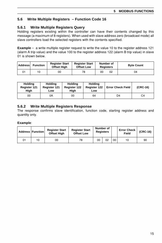
5.6 Write Multiple Registers – Function Code 16
5.6.1 Write Multiple Registers QueryHolding registers existing within the controller can have their contents changed by thismessage (a maximum of 8 registers). When used with slave address zero (broadcast mode) allslave controllers load the selected registers with the contents specified.
Example – a write multiple register request to write the value 10 to the register address 121(alarm A trip value) and the value 100 to the register address 122 (alarm B trip value) in slave01 is shown below.
5 MODBUS FUNCTIONS
5.6.2 Write Multiple Registers ResponseThe response confirms slave identification, function code, starting register address andquantity only.
Example:
sserddA noitcnuFtratSretsigeR
hgiHtesffOtratSretsigeR
woLtesffOforebmuN
sretsigeRtnuoCetyB
10 01 00 87 2000 40
gnidloH121retsigeR
hgiH
gnidloH121retsigeR
woL
gnidloH221retsigeR
hgiH
gnidloH221retsigeR
woLdleiFkcehCrorrE )61-CRC(
00 A0 00 46 4D 4C
sserddA noitcnuFtratSretsigeR
hgiHtesffOtratSretsigeR
woLtesffO
forebmuNsretsigeR
kcehCrorrEdleiF
)61-CRC(
10 01 00 87 00 20 00 01 09

16
6 EXCEPTION RESPONCES
The exception response codes sent by the slave are shown in Table 6.1. When a slave detectsone of these errors, it sends a response message to the master consisting of slave address,function code, error code and error check fields.
Table 6.1 Exception Response Codes
The response is an exception response sighting ‘illegal data address’. To indicate that theresponse is a notification of an error, the most significant bit of the function code is set to 1.
6.1 ExamplesA read register request to read holding register address 251 of slave 01 (undefined address forslave, beyond address limit) is shown below.
noitpecxEesnopseR
edoC
esnopseRnoitpecxEemaN
noitinifeDesnopseRnoitpecxE
10 noitcnuFlagellIrofnoitcaelbawollanatonsideviecernoitcnufegassemehT
.002Ceht
20 sserddAataDlagellIelbawollanatonsidleifatadehtniecnerefersserddaehT
.002Cehtrofsserdda
30 eulaVataDlagellIehtnielbawollatonsidleifatadehtnidecnerefereulavehT
.noitacolevalsdesserdda
70 tnemegdelwonkcAevitageN .demrofrepebtonnacdetseuqertsujnoitcnufehT
80 rorrEytiraPyromeMehtfoeromroenonirorrenasetacidnikcehcytiraP
.deviecersretcarahc
sserddA noitcnuFtratSretsigeR
hgiHtesffO
retsigeRtratS
woLtesffO
forebmuNsretsigeR
hgiH
forebmuNsretsigeR
woL
kcehCrorrEdleiF
)61-CRC(
10 30 00 AF 00 60 5E 9F
sserddAevalS noitcnuF edoCnoitpecxE dleiFkcehCrorrE )61-CRC(
10 38 20 0C 1F

17
7 MODBUS REGISTERS
7.1 Coils
Coil Number Read/Write Description Response/Entry
Input Failure States011 R Process Variable012 R Position Feedback 0 = Active, 1 = Failed013 R Remote Set Point
Alarm Status031 R Alarm A032 R Alarm B033 R Alarm C034 R Alarm D035 R Alarm E036 R Alarm F037 R Alarm G 0 = Inactive038 R Alarm H 1 = Active039 R Alarm J040 R Alarm K041 R Alarm 1Relay042 R Alarm 2 Relay043 R Alarm 3 Relay044 R Alarm 4 Relay
Digital Input States051 R Logic Input 1052 R Logic Input 2 0 = Active053 R Logic Input 3 1 = Inactive054 R Logic Input 4
Multiple Read Group061 R Alarm A062 R Alarm B063 R Alarm C064 R Alarm D065 R Alarm E 0 = Inactive066 R Alarm F 1 = Active067 R Alarm G068 R Alarm H069 R Alarm J070 R Alarm K071 R Logic Input 1 0 = Active, 1 = Inactive072 R Logic Input 2 0 = Active, 1 = Inactive073 R Control Action 0 = Direct,1 = Reverse074 R Auto/Manual 0 = Auto, 1 = Manual075 R Control Action for Output 2 0 = Direct,1 = Reverse076 R Process Variable Failure 0 = Active, 1 = Failed

18
…7 MODBUS REGISTERS
…7.1 Coils
Coil Number Read/Write Description Response/Entry
Control States148 R/W Control Action 0 = Direct, 1 = Reverse149 R/W Auto/Manual 0 = Auto, 1 = Manual150 R/W Control Action for Output 2 0 = Direct, 1 = Reverse
Save Modbus181 R/W Enable Writes to Non-Vol Memory 0 = Disable, 1= Enable
7.2 Holding Registers
Information.Holding registers which have a response entry of 0 to 4095 are numbers scaled over thedisplay range.
Example – scaling process variable to display range:• Process variable display high = 1000• Process variable display low = 0• Process variable response (011) = 2047
Scaled value = x (Display High – Display Low) + Display LowResponse4095
Process Variable = x (1000 – 0) + 020474095
Process Variable = 500
Register No. Read/Write Description Response/Entry
Process Variable Inputs011 R Process Variable012 R Remote Set Point Scaled 0 to 4095013 R Postion Feedback of Display Range019 R Process Variable Display Decimal
Point Position 0 to 3 Decimal Places041 R Process Variable Display Span042 R Process Variable Display Zero043 R Remote Set Point High044 R Remote Set Point Low
–9999 to +9999

19
7.3 Controller Settings/Outputs
Register No. Read/Write Description Response/Entry
Controller Settings051 R Process Variable052 R/W Control Set Point 0 to 4095053 R/W Control Output*054 R Position Feedback Input 0 to 4095055 R Position Feedback Failure State 0 = Active, 1 = Failed057 R/W Cycle Time 10 to 3000058 R/W Proportional Band 1 to 9999059 R/W Integral Action Time 0 to 7201060 R/W Manual Reset Value 0 to 4095061 R/W Derivative Action Time 1 to 9999062 R/W Approach Band 1 to 30063 R/W Control Output Heat 0 to 4095064 R/W Control Output Cool 0 to 4095065 R/W Proportional Band Cool 1 to 9999066 R/W Intregral Action Time Cool 0 to 7200067 R/W Manual Reset Cool 0 to 4095068 R/W Cycle Time Cool 10 to 3000069 R/W Crossover Value 0 to 4095070 R/W Transition Band 0 to 4095071 R Remote Set Point Input074 R/W Ratio Value for Remote Set Point 10 to 9999075 R/W Bias Value for Remote Set Point ± Display Range)
Controller Settingsfor Position Feedback
094 R/W Ratio Value for Position Feedback 0 to 999095 R/W Bias Value for Position Feedback ± 100
Set Points101 R/W Local Set Point102 R/W Dual Set Point 0 to 4095103 R/W Remote Set Point (without Ratio/Bias) (Display Range)104 R/W Remote Set Point (with Ratio/Bias)105 R/W Remote Set Point Failure State 0 = Active, 1= Failed106 R/W Set Point Selection 0 = Local,1 = 2nd SP
* Only applicable for time proportioning and current proportioning. NOT position proportioningor boundless.
7 MODBUS REGISTERS…

20
…7 MODBUS REGISTERS
7.4 Alarm Settings
Register No. Read/Write Description Response/Entry
Alarms121 R/W Alarm A Trip Value122 R/W Alarm B Trip Value123 R/W Alarm C Trip Value124 R/W Alarm D Trip Value125 R/W Alarm E Trip Value126 R/W Alarm F Trip Value 0 to 4095127 R/W Alarm G Trip Value128 R/W Alarm H Trip Value129 R/W Alarm J Trip Value130 R/W Alarm K Trip Value
0 = Alarm Off141 R Alarm A Type 1 = High Process142 R Alarm B Type 2 = Low Process143 R Alarm C Type 3 = High Deviation144 R Alarm D Type 4 = Low Deviation145 R Alarm E Type 5 = High Output146 R Alarm F Type 6 = Low Output147 R Alarm G Type 7 = Fast Rate148 R Alarm H Type 8 = Slow Rate149 R Alarm J Type 9 = Mode Alarm150 R Alarm K Type 10 = Program Event
11 = Segment Event
7.5 Ramp/Soak Settings
Register No. Read/Write Description Response/Entry
Ramp Soak Settings171 W Ramp Soak Run State 1 = Run Profile172 W Ramp Soak Hold Command 1 = Hold Profile173 W Ramp Soak Skip 1 = Skip175 W Ramp Soak Reset 1 = Reset Profile
0 = Stop1 = Ramp3 = Soak4 = Countdown
176 R Profile Status 5 = Operator Hold6 = Not Used7 = Manual Hold8 = Holdback Hold9 = End
178 R Remaining Segment Time 0 to 9999179 R/W Selected Program 1 to10

PRODUCTS & CUSTOMER SUPPORT
A Comprehensive Product RangeAnalytical Instrumentation
• TransmittersOn-line pH, conductivity, and dissolved oxygentransmitters and associated sensing systems.
• SensorspH, redox, selective ion, conductivity anddissolved oxygen.
• Laboratory InstrumentationpH and dissolved oxygen meters and associatedsensors.
• Water AnalyzersFor water quality monitoring in environmental,power generation and general industrialapplications including: pH, conductivity, ammonia,nitrate, phosphate, silica, sodium, chloride,fluoride, dissolved oxygen and hydrazine.
• Gas AnalyzersZirconia, paramagnetic, infrared, thermalconductivity.
Controllers & Recorders• Controllers
Digital display, electronic, pneumatic. Discretesingle-loop and multi-loop controllers which canbe linked to a common display station, processcomputer or personal computer.
• RecordersCircular and strip-chart types (single and multi-point) for temperature, pressure, flow and manyother process measurements.
Electronic Transmitters• Smart & Analog Transmitters
For draft, differential, gauge and absolutepressure measurement. Also, liquid level andtemperature.
• I to P Converters and Field Indicators
Flow Metering• Magnetic Flowmeters
Electromagnetic, insertion type probes andwatermeters.
• Turbine Flowmeters
• Wedge Flow Elements
• Mass Flow MetersTransmitters, sensors, controllers and batch/display units.
Level Control• Submersible, Capacitance & Conductivity.
Pneumatic Instrumentation• Transmitters
• Indicating Controllers
• Recording Controllers
Customer SupportABB Instrumentation provides a comprehensive aftersales service via a Worldwide Service Organization.Contact one of the following offices for details on yournearest Service and Repair Centre.
United KingdomABB Instrumentation LimitedTel: +44 (0)1480 475321Fax: +44 (0)1480 470787
United States of AmericaABB Automation Inc.Instrumentation DivisionTel: +1 215-674-6000Fax: +1 215-674-7183
ItalyABB Instrumentation SpATel: +39 (0) 344 58111Fax: +39 (0) 344 58278
Client Warranty
Prior to installation, the equipment referred to inthis manual must be stored in a clean, dryenvironment, in accordance with the Company'spublished specification. Periodic checks must bemade on the equipment's condition.
In the event of a failure under warranty, thefollowing documentation must be provided assubstantiation:
1. A listing evidencing process operation andalarm logs at time of failure.
2. Copies of operating and maintenance recordsrelating to the alleged faulty unit.

IM/C
300–
MO
DIs
sue
7
The Company's policy is one of continuous productimprovement and the right is reserved to modify theinformation contained herein without notice.
© ABB 2000 Printed in UK (07.00)
ABB Instrumentation LtdSt. NeotsCambs.England, PE19 8EUTel: +44 (0) 1480 475321Fax: +44 (0) 1480 217948
ABB Automation Inc.Instrumentation Division125 E. County Line RoadWarminster, PA 18974 USATel: +1 215-674-6000Fax: +1 215-674-7183
ABB Instrumentation SpA22016 LennoComoItalyTel: +39 (0) 344 58111Fax: +39 (0) 344 58278