Apollo Experience Report Command and Service Module Controls and Displays Subsystem
1
High Energy Solar Spectroscopic Imager (HESSI)
Command & Data Handling Subsystem (C&DHS)Training Package
Mike Matranga10/17/00

2
High Energy Solar Spectroscopic Imager (HESSI)
C&DH Overview
C&DH Components:
• Spacecraft Electronics Module (SEM)– 6U VME Enclosure w/7 slot backplane– PACI – CIB– CPU RAD6K– CCB (EPS)– PCB (EPS)– ADB (EPS)
• Solid State Recorder– 32.0 Gbit– 40 Mbit/sec transfer rates– Stores all science data output
• Oven Controlled Crystal Oscillator (OCXO)– 2^24 Hz clock– Used as global system clock– Physically mounted in baseplate of SEM
SEM
SSR

3
High Energy Solar Spectroscopic Imager (HESSI)
PACI Overview
Payload & Attitude Control Interface (PACI) Functions:
• SOH Data Acquisition– AD590 Temperature Sensors– PRT Temperature Sensors– IAD Motor Position– Coarse Sun Sensor– General Purpose Analogs– General Purpose Digital
• Time Management– Distributes 1 MHz and 1 Hz master clock to IDPU, CIB
• Serial Communications– Communicates with IDPU and LV via 9600 Baud UART– Communicates with SSR via High Speed Serial (HSS) Interface
• Memory Storage– 256K, PACI Data Storage– 256K, CPU Data Storage (w/128K EDAC backup)

4
High Energy Solar Spectroscopic Imager (HESSI)
PACI SOH Data Acquisition
Details:• PACI scans (samples and converts) all channels 8 times per second
– Hardware controlled. FSW cannot interrupt this process
• Scan Data is stored and “packetized” into 1098 byte VC0, APID 0
• PACI Time Stamps when data was recorded and stores in Packet Time Field
• PACI Transmits 1st 200 bytes to Pegasus via 9,600 baud serial interface– Note: Only occurs if Pegasus send the “Poll Message”: ox33, 0xAA
• PACI Transmits full 1098 byte frame to CIB via backplane interface
• PACI / CPU Interaction– With CPU OFF, PACI will always set APID to 0– Only 1st 200 bytes of packet are valid– With CPU ON, FSW adds FSW data and sets APID to 1
• PACI / CIB Interaction– Default (Power On) PACI Packet Rate is 8 Hz– HCD Bit 17 Toggles Between PACI 1 Hz / 8 Hz operation
– OFF (0) = 8 Hz– ON (1) = 1 Hz
5
High Energy Solar Spectroscopic Imager (HESSI)
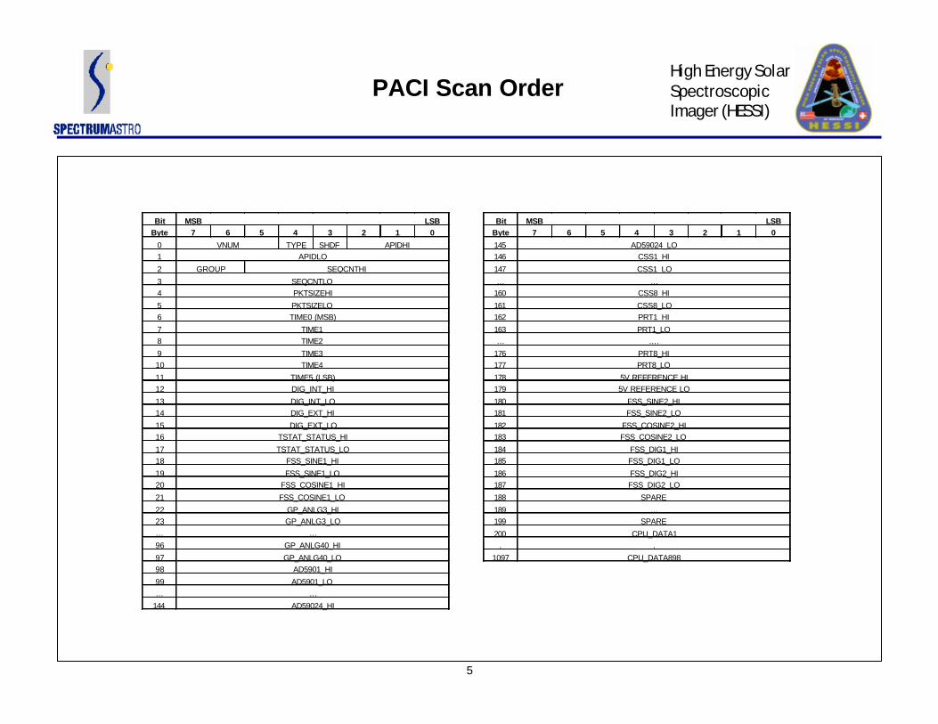
PACI Scan Order
Bit MSB LSBByte 7 6 5 4 3 2 1 0
0 VNUM TYPE SHDF APIDHI1 APIDLO
2 GROUP SEQCNTHI
3 SEQCNTLO4 PKTSIZEHI
5 PKTSIZELO6 TIME0 (MSB)
7 TIME18 TIME2
9 TIME310 TIME4
11 TIME5 (LSB)12 DIG_INT_HI
13 DIG_INT_LO14 DIG_EXT_HI
15 DIG_EXT_LO16 TSTAT_STATUS_HI
17 TSTAT_STATUS_LO18 FSS_SINE1_HI
19 FSS_SINE1_LO20 FSS_COSINE1_HI
21 FSS_COSINE1_LO
22 GP_ANLG3_HI23 GP_ANLG3_LO… …
96 GP_ANLG40_HI
97 GP_ANLG40_LO98 AD5901_HI
99 AD5901_LO… …
144 AD59024_HI
Bit MSB LSBByte 7 6 5 4 3 2 1 0
145 AD59024_LO146 CSS1_HI
147 CSS1_LO
… …160 CSS8_HI
161 CSS8_LO162 PRT1_HI
163 PRT1_LO… ….
176 PRT8_HI177 PRT8_LO
178 5V REFERENCE HI179 5V REFERENCE LO
180 FSS_SINE2_HI181 FSS_SINE2_LO
182 FSS_COSINE2_HI183 FSS_COSINE2_LO
184 FSS_DIG1_HI185 FSS_DIG1_LO
186 FSS_DIG2_HI187 FSS_DIG2_LO
188 SPARE
189 …199 SPARE
200 CPU_DATA1. .
1097 CPU_DATA898

6
High Energy Solar Spectroscopic Imager (HESSI)
PACI Telemetry

7
High Energy Solar Spectroscopic Imager (HESSI)
PACI Time Management
Time Management:
• Time is represented by 32 bit unsegmented number with 16 bit offset (sub-seconds)– 32 bit seconds– 16 bit sub-seconds
• PACI Divides 224 Clock by 16 to get 220 (1.024 MHz) Master Spacecraft Clock– Internally divides clock again by 16 to get 216 (65.536 kHz) sub-second clock
• Every 220 “ticks”, PACI issues a 1 Hz sync pulse– All users should “reset” their sub-seconds counters to 0– Keeps everyone in sync with each other
• Two Commands for setting / adjusting time– /SMSCLKSET Sets the 32 bit seconds field in S/C clock– /SMSCLKDELTA Adjusts the 32 bit seconds by +/- commanded seconds

8
High Energy Solar Spectroscopic Imager (HESSI)
PACI Serial Interfaces
SSR Interface:• PACI “polls” the SSR telemetry once per second
– 3 wire interface consisting of clock, data, enable– 1.0 Mbits/sec transfer rates
• Software Controlled Process
LV Interface:• PACI only responds to LV when it receives the Pegasus Poll Message (0x33, 0xAA)• PACI responds with 200 byte “packet” consisting of the VC0, APID0, SOH data• Hardware Controlled Process
– 9600, 8 data, 1 start, 1 stop, no parity– Cannot be interrupted by FSW
IDPU Interface:• PACI “polls” the IDPU telemetry once per second• Command / Telemetry rate is 38.4K baud• Software Controlled Process
– Multiple commands can be sent within one second– Payload telemetry included in VC0, APID 1 packet

9
High Energy Solar Spectroscopic Imager (HESSI)
PACI Memory
PACI Memory:
• PACI contains 256K byte of General Purpose SRAM– SOH data buffers– Serial Transmit/Receive Buffers– LV Telemetry Buffer
• PACI contains additional 256K buffer for CPU memory only– Has an additional 128K used exclusively for EDAC– Used to backup stored SOH data in case of upset– FSW stores last 250 SOH frames in circular buffer– EDAC scrub rate is fixed
10
High Energy Solar Spectroscopic Imager (HESSI)
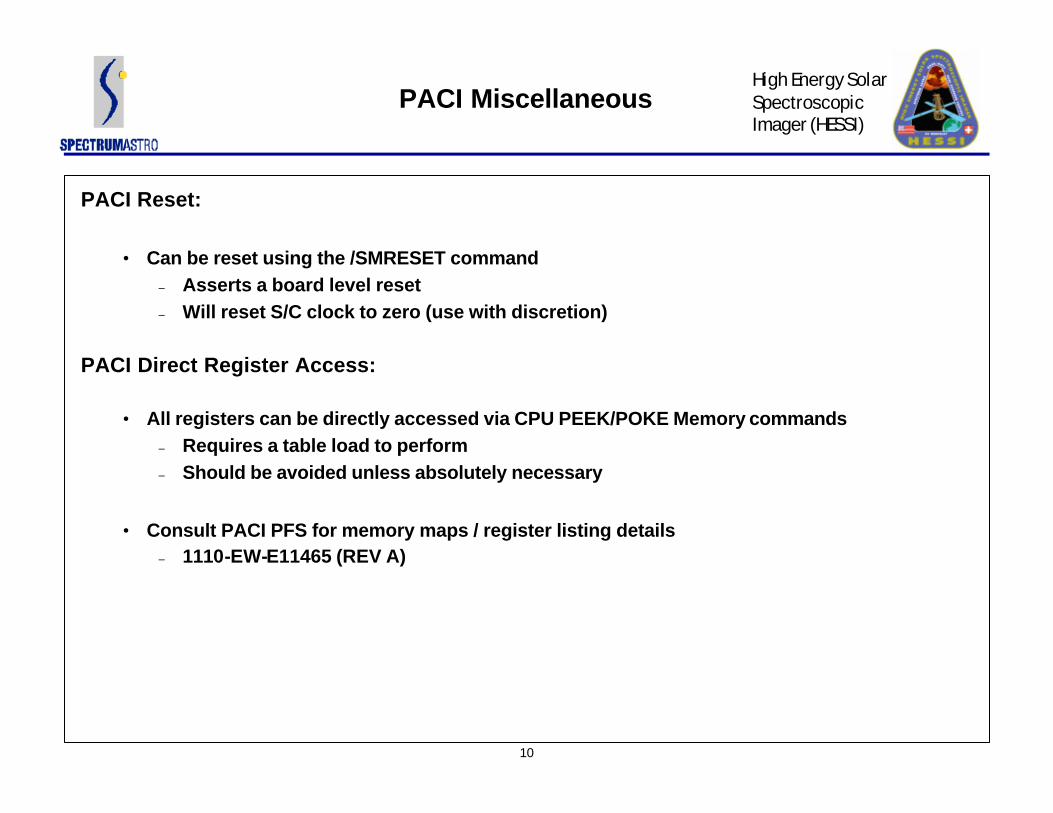
PACI Miscellaneous
PACI Reset:
• Can be reset using the /SMRESET command– Asserts a board level reset– Will reset S/C clock to zero (use with discretion)
PACI Direct Register Access:
• All registers can be directly accessed via CPU PEEK/POKE Memory commands– Requires a table load to perform– Should be avoided unless absolutely necessary
• Consult PACI PFS for memory maps / register listing details– 1110-EW-E11465 (REV A)

11
High Energy Solar Spectroscopic Imager (HESSI)
CIB Overview
Communications Interface Board (CIB) Functions:
• Telemetry Frame Formatting and Downlink– Attaches Frame Headers to Packets– Link Priority Management– Reed Solomon Encoding– Pseudo Noise Randomization– CLCW (FARM) Control– Selectable Downlink Rate (from 125Kbps to 4Mbps)
• Command Uplink– Hardware Command Decoding– Software Command Buffering
• Watchdog Timer– Resets CPU on Timeout
• SSR Interface– Communicates directly with SSR for science data output

12
High Energy Solar Spectroscopic Imager (HESSI)
CIB Block Diagram
CIB FUNCTIONAL BLOCK DIAGRAM
RSE16ASIC
GSECLK
GSEDAT
SCATor
GSE
XPNDR
FRAMEFORMAT
FPGA
GSESEL
HCDASIC
CMDCLK
CMDDAT
CMDENA
TLMCLK
TLMDAT
RS-422
RS-422
CLK+CLK-DAT+DAT-
CLK+CLK-DAT+DAT-ENA+ENA-
HCDFPGA
128KSRAM
DIN(8)
DOUT(8)CLKINC
128KSRAM
VMEFPGA
BUFF
H/WCMD (24)
VMEP1/P2
HCD(24)
ADDR
DATACTRLIRQ
RS-422
SCATor
GSERS-422
CMDCLK
CMDDAT
CMDENA
GSESEL
SSR
128KSRAM
HPLYCLKRPLYCLK
RPLYDAT(0:7)RPLYVLD
SSRDATA(8)SSRADR(16)
FILLCLCW
LOCAL BUS
CMDWCLKRCLK
PACISSR
FPGA
128KSRAM
SSRCTL(4)
PACI_CLKPACI_DAT
PACI_ENA
1HZ1MHz
WDOG
SSR_RDYSSR_ACK
TIME_CLK
PACI_RDYPACI_ACK
TIME_RDY
TIME_ACK
DATA(8)DATA_CLK
128KSRAM
128KSRAM
SSOH DL Buffer
CMD UL Buffer
SSOH_RDYSSOH_ACK
HPLYRDYRST
PACIDATA(8)PACIADR(16)
PACICTL(4)
CLK+
CLK-DAT+DAT-
CLK+CLK-DAT+DAT-ENA+ENA-

13
High Energy Solar Spectroscopic Imager (HESSI)
CIB Telemetry Frame Formatting
Donwlink Process:
• Frames are generated as follows:– CIB outputs Attached Sync Marker (ASM) 0x1ACFFC1D– CIB selects the next packet with the highest priority– Packet Priorities are: (0 = highest)
– 0 = Real Time SOH– 1 = Stored SOH– 2 = Real Time Science– 3 = Stored Science– 7 = Fill Data
– CIB adds header information (frame time stamp, VCID)– CIB outputs 1098 bytes of packet data– CIB outputs CLCW (Command Link Control Word)– CIB outputs 160 bytes of Reed Solomon Data– CIB runs data through Pseudo Noise Encoder (PSN) prior to output to transmitter
14
High Energy Solar Spectroscopic Imager (HESSI)
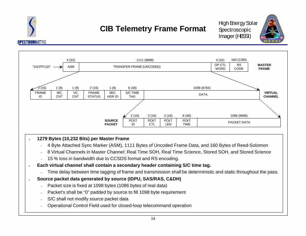
CIB Telemetry Frame Format
ASM TRANSFER FRAME (UNCODED) RS CODE
4 (32) 1111 (8888) 4 (32)
“1ACFFC1D”
FRAMEID
MCCNT
S/C TIMETAG
VCCNT
FRAMESTATUS
SECHDR ID
DATA
2 (16) 1 (8) 6 (48)1 (8) 2 (16) 1 (8) 1098 (8784)
PCKTID
PCKTCTL
PACKET DATAPCKTLEN
PCKTTIME
2 (16) 2 (16) 2 (16) 6 (48) 1086 (8688)
MASTERFRAME
VIRTUALCHANNEL
SOURCEPACKET
l 1279 Bytes (10,232 Bits) per Master Frame– 4 Byte Attached Sync Marker (ASM), 1111 Bytes of Uncoded Frame Data, and 160 Bytes of Reed-Solomon– 8 Virtual Channels in Master Channel: Real Time SOH, Real Time Science, Stored SOH, and Stored Science– 15 % loss in bandwidth due to CCSDS format and RS encoding.
l Each virtual channel shall contain a secondary header containing S/C time tag.– Time delay between time tagging of frame and transmission shall be deterministic and static throughout the pass.
l Source packet data generated by source (IDPU, SAS/RAS, C&DH)– Packet size is fixed at 1098 bytes (1086 bytes of real data)– Packet’s shall be “0” padded by source to fill 1098 byte requirement– S/C shall not modify source packet data– Operational Control Field used for closed-loop telecommand operation
OP CTLWORD
160 (1280)
15
High Energy Solar Spectroscopic Imager (HESSI)
CIB Data Sources
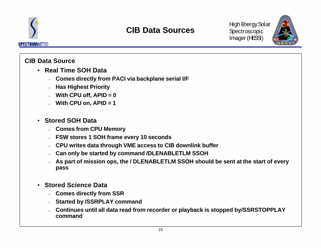
CIB Data Source• Real Time SOH Data
– Comes directly from PACI via backplane serial I/F– Has Highest Priority– With CPU off, APID = 0– With CPU on, APID = 1
• Stored SOH Data– Comes from CPU Memory– FSW stores 1 SOH frame every 10 seconds– CPU writes data through VME access to CIB downlink buffer– Can only be started by command /DLENABLETLM SSOH– As part of mission ops, the / DLENABLETLM SSOH should be sent at the start of every
pass
• Stored Science Data– Comes directly from SSR– Started by /SSRPLAY command– Continues until all data read from recorder or playback is stopped by/SSRSTOPPLAY
command
16
High Energy Solar Spectroscopic Imager (HESSI)
CIB Data Sources
CIB Data Source (Continued)
• Real Time Science Data– Also comes directly from SSR, but FSW changes the VCID to 2– Started by /SSRPLAYRTSCI command– Continues until requested number of frames are dumped

17
High Energy Solar Spectroscopic Imager (HESSI)
CIB Command Uplink
Uplink Commands:
• Hardware Command Decoding– All VC0 commands are decoded by Hardware Command Decode (HCD) chip– All VC0 commands must be sent using RAWTF format of ITOS– HCD (VC0) Commands can be used to set 1 of 24 bits ON or OFF

18
High Energy Solar Spectroscopic Imager (HESSI)
CIB HCD Commands
HCD Notes:• CRC0
– Asserts a VME SYSRESET on the backplane. This will reboot the CPU (CTRL-ALT-DEL)• CRC2
– Transmitter will automatically timeout after 15 minutes– Must turn off and then on to reset 15 minute timer. May need to do this for passes > 15
minutes.• CRC4 to CRC9
– Used as a backup means for manually controlling the solar array release mechanisms– DO NOT ACTIVATE for mission ops. They consume a lot of power and will needlessly
drain the battery• CRC12 to CRC15
– VT Curve Select Bits– Default value should be the appropriate setting for the mission– May need to bump VT level higher later on in mission (Refer to EPS briefing on VT curve
settings)• CRC20
– Reserved for special function– Toggle CRC20 ON/OFF 3 times within 1 minute to start the solar array deployment
sequence

19
High Energy Solar Spectroscopic Imager (HESSI)
HCD EFC Bits
HCD EFC Bits:
• Used to allow flight software to control the HCD bits via a VC1 command• EFC bits can only be set/cleared by VC0 command

20
High Energy Solar Spectroscopic Imager (HESSI)
Uplink Commands, VC1
VC1 Commands:
• All uplink commands are stored and buffered by CIB
• Each TC Codeblock of command string generates a CPU interrupt
• CPU waits until full command is received before processing it
• Command uplink rate is 2.0 Kbps
• All VC1 commands are generated from ITOS command database
• All VC1 commands have the form:– /CMDMNEMONIC PARAMETER1, PARAMETER2, etc.
• Command log history can be obtained by:– /DLENABLETLM TCLOG

21
High Energy Solar Spectroscopic Imager (HESSI)
Command Problems
Command Rejects:
• If commands are rejected– First check to make sure that the spacecraft is in “lock” and receiving telemetry– Verify ITOS is in sync with the current CLCW
– If not, issue a “resync” command at the ITOS STOL prompt– Check the command accept/reject counters
– Open the FSWMENU display page– This will tell you if the commands are being received, but are being rejected by FSW
– Check the HCD command registers– Open the CIB device telemetry page– Check the HCD command register bits– Make sure commands are being sent on the correct uplink channel (A or B)
22
High Energy Solar Spectroscopic Imager (HESSI)
CIB Watchdog Timer
Watchdog Timer:
• Watchdog Timeout Period is 128 seconds
• Watchdog is refreshed by flight software once/second
• If dog is not fed after 128 seconds, CIB will issue a SYSRESET to reboot the CPU
• If the CPU does not respond to 3 consecutive watchdog timer time-outs, the CIB power cycles the CPU
– NOTE: This may occur on-orbit (with low probability) if the code contained in the EEPROM is corrupted. The backup plan is to switch to the alternate copy of the flight software by sending HCD command 22

23
High Energy Solar Spectroscopic Imager (HESSI)
Solid State Recorder
Solid State Recorder:
• Manufactured by SEAKR Engineering, Engelwood CO
• 32.0 Gbits total storage capacity
• 40 Mbps record rate capability– 40 Mbps transfer rate from IDPU to SSR
• 40 Mbps playback rate capability– 4 Mbps transfer rate from SSR to CIB
• Internal self-test and diagnostic ability

24
High Energy Solar Spectroscopic Imager (HESSI)
SSR Normal Operations
SSR Normal Ops:
• Create a partition once at beginning of mission using /SSRMAKEPART command– Should take about 30 minutes to complete– Erases all data stored in recorder– /SSRMAKEPART command configures 1 giant partition in a circular buffer mode
• Start data recording at offset = 0 – /SSRRECORD STARTOFFSET=0
• Start data playback at next pass– /SSRPLAY BYPASSEDAC = 0

25
High Energy Solar Spectroscopic Imager (HESSI)
SSR Partition
SSRMEMORY
RECORD PTR PLAY PTR
RECORD PTRAFTER ONE PASS

26
High Energy Solar Spectroscopic Imager (HESSI)
SSR Operations
NOTES:
• Start of where data is recorded is controlled by start command offset
• Playback pointer is controlled by /SSRSETPLYPTR PLAYPOINTER=X
• If playback pointer not changed (via above), next /SSRPLAY will begin where it left off
• If record stopped (via /SSRSTOPRECORD command), need to keep track of record pointer so as to not to overwrite data
BENEFITS:
• Same data can be played back multiple times (if ground not ready, etc.)

27
High Energy Solar Spectroscopic Imager (HESSI)
Real Time Science Data
Real Time Science Data Playback:
• Started by /SSRPLAYRTSCI NUMPACKETS=X, FALSE
• FSW commands the SSR playback pointer equal to current value of record pointer - X
• Playback is started with size set to X number of packets
• Upon completion of RT playback, playback pointer is reset to where it was before command
• Eventually, data will be played back again (twice)– A little inefficient, but really helps out during ground test

28
High Energy Solar Spectroscopic Imager (HESSI)
SSR Extras
SSR Command Set:
• SSR has many more commands available that what is offered by HESSI FSW– FSW offers a subset of SSR commands
• Full SSR command set is available via /SSRPASSTHRU command– SSR Pass Thru command just takes raw data and sends it to the SSR– Flight software automatically appends a checksum prior to sending it to the SSR
• All SSR commands are documented in SSR Flight Software User’s Manual (Rev A)