ankurm.com Com/Experiments/Study of... · Web viewAim: Study of GSM Model Theory: GSM (Global...
24
Aim: Study of GSM Model Theory: GSM (Global System for Mobile communications) is an open, digital cellular technology used for transmitting mobile voice and data services. GSM supports voice calls and data transfer speeds of up to 9.6 kbps, together with the transmission of SMS (Short Message Service). GSM operates in the 900MHz and 1.8GHz bands in Europe and the 1.9GHz and 850MHz bands in the US. GSM services are also transmitted via 850MHz spectrum in Australia, Canada and many Latin American countries. The use of harmonised spectrum across most of the globe, combined with GSM’s international roaming capability, allows travellers to access the same mobile services at home and abroad. GSM enables individuals to be reached via the same mobile number in up to 219 countries. Terrestrial GSM networks now cover more than 90% of the world’s population. GSM satellite roaming has also extended service access to areas where terrestrial coverage is not available. GSM Architecture The GSM network can be divided into three main parts: The Base Station Subsystem (BSS) The Network and Switching Subsystem (NSS) The Operation and Support Subsystem (OSS) Radio Station Subsystem
Transcript of ankurm.com Com/Experiments/Study of... · Web viewAim: Study of GSM Model Theory: GSM (Global...

Aim: Study of GSM Model
Theory:
GSM (Global System for Mobile communications) is an open, digital cellular technology used
for transmitting mobile voice and data services. GSM supports voice calls and data transfer
speeds of up to 9.6 kbps, together with the transmission of SMS (Short Message Service). GSM
operates in the 900MHz and 1.8GHz bands in Europe and the 1.9GHz and 850MHz bands in the
US. GSM services are also transmitted via 850MHz spectrum in Australia, Canada and many
Latin American countries. The use of harmonised spectrum across most of the globe, combined
with GSM’s international roaming capability, allows travellers to access the same mobile
services at home and abroad. GSM enables individuals to be reached via the same mobile
number in up to 219 countries. Terrestrial GSM networks now cover more than 90% of the
world’s population. GSM satellite roaming has also extended service access to areas where
terrestrial coverage is not available.
GSM Architecture
The GSM network can be divided into three main parts:
The Base Station Subsystem (BSS)
The Network and Switching Subsystem (NSS)
The Operation and Support Subsystem (OSS)
Radio Station Subsystem
The RSS provides the interface between the ME and the NSS. It is in charge of the transmission
and reception. It may be divided into two parts:
Base Station Controller (BSC): It controls a group of BTSs and manages their radio
ressources. A BSC is principally in charge of handoffs, frequency hopping, exchange
functions and power control over each managed BTSs.
Base Transceiver Station (BTS) or Base Station: It maps to transceivers and antennas
used in each cell of the network. It is usually placed in the center of a cell. Its transmitting

power defines the size of a cell. Each BTS has between 1-16 transceivers depending on
the density of users in the cell.
Mobile Station
A Mobile Station consists of two main elements:
o The Subscriber Identity Module (SIM): It is protected by a four-digit Personal
Identification Number (PIN). In order to identify the subscriber to the system, the
SIM card contains amongst others a unique International Mobile Subscriber
Identity (IMSI). User mobility is provided through maping the subscriber to the
SIM card rather than the terminal as we done in past cellular systems.
o Mobile equipment/terminal (ME): The actual device used for communication.
Fig: GSM Architecture
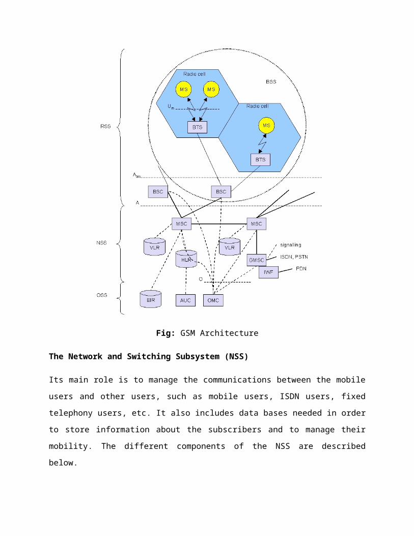
The Network and Switching Subsystem (NSS)
Its main role is to manage the communications between the mobile users and other users, such as
mobile users, ISDN users, fixed telephony users, etc. It also includes data bases needed in order
to store information about the subscribers and to manage their mobility. The different
components of the NSS are described below.
MSC: the central component of the NSS. The MSC performs the switching functions of
the network. It also provides connection to other networks.
GMSC: A gateway that interconnects two networks: the cellular network and the PSTN.
It is in charge of routing calls from the fixed network towards a GSM user. The GMSC is
often implemented in the same machines as the MSC.
HLR: The HLR stores information of the subscribers belonging to the coverage area of a
MSC; it also stores the current location of these subscribers and the services to which
they have access. The location of the subscriber maps to the SS7 address of the Visitor
Location Register (VLR) associated to the MN.
VLR: contains information from a subscriber's HLR necessary to provide the subscribed
services to visiting users. When a subscriber enters the covering area of a new MSC, the
VLR associated to this MSC will request information about the new subscriber to its
corresponding HLR. The VLR will then have enough data to assure the subscribed
services without needing to ask the HLR each time a communication is established. The
VLR is always implemented together with a MSC; thus, the area under control of the
MSC is also the area under control of the VLR.
GSM Interworking Unit (GIWU): The GIWU provides an interface to various
networks for data communications. During these communications, the transmission of
speech and data can be alternated.
Operation and Support Subsystem (OSS)
It is connected to components of the NSS and the BSC, in order to control and monitor the GSM
system. It is also in charge of controlling the traffic load of the BSS. It must be noted that as the
number of BS increases with the scaling of the subscriber population some of the maintenance
tasks are transferred to the BTS, allowing savings in the cost of ownership of the system.

Authentication Center (AuC): It serves security purposes; it provides the parameters
needed for authentication and encryption functions. These parameters allow verification
of the subscriber's identity.
Equipment Identity Register (EIR): EIR stores security-sensitive information about the
mobile equipments. It maintains a list of all valid terminals as identified by their
International Mobile Equipment Identity (IMEI). The EIR allows then to forbid calls
from stolen or unauthorized terminals (e.g, a terminal which does not respect the
specifications concerning the output RF power).
GSM Protocol stack
Fig: Protocol Architecture for signaling
Above figure shows the architecture of protocols used within the GSM system, with signaling
protocols, interfaces as well as the entities.

Again the main area of focus is in the Um interface, this is because the other interfaces occur
between entities in a fixed network. The physical layer, Layer 1 handles all the radio specific
functions. This layer includes the creation of bursts according to the five different formats, the
multiplexing of bursts into TDMA frames, synchronization with the BTS, detection of the idle
channels and the measurement of the channel quality on the downlink. At Um, the physical layer
uses GSMK (Gaussian Shift Minimum Keying) for the digital modulation and performs
encryption/decryption of data This means that encryption is not performed end-to-end, but only
between MS and BTS over the air interface.
The synchronization also includes the correction of the individual path delay between the MS
and the BTS, all MSs within a cell can use the same BTS and hence must be synchronized to the
BTS. This is due to the fact that the BTS generated the time-structure of the frames and slots etc.
This can be problematic since in this context there are different RTTs (Round Trip Time).
Therefore the BTS sends the current RTT to MS, which then adjusts its access time so that all
bursts reach the BTS within their limits.
The physical layer has several main tasks that comprise the channel coding, error
detection/correction; this is directly combined with the coding mechanisms. FEC (Forward Error
Correction) is used extensively in the coding channel, FEC adds redundancy to the user data,
thus allowing for the detection and correction of selected errors. The power of the FEC scheme
depends on the amount of redundancy, coding algorithm, and any further interleaving of data to
minimize the effects of burst errors. Whats more the FEC is the reason that error
detection/correction occurs in the physical layer. This differs to the ISO/OSI reference model
where it occurs in layer two. The GSM physical layer tries to correct errors, however it does not
deliver erroneous data to the higher layers.
GSM logical channels use different coding schemes with different correction capabilities, for
example speech channels need the additional coding of voice data after analogue to digital
conversion. This is in order to reach a data rate of 22.8 kbit/s (using the 13 kbit/s from the voice
codec plus redundancy, CRC bits, and interleaving. When GSM was envisaged it was assumed
that voice would be the main service so the physical also contains special functions, for instance
VAD (Voice Activity Detection), which transmits voice data only when there is a voice signal.

In the duration between voice activity, the physical layer generates a comfort noise to fake a
connection, however no actual transmission takes place.
Signaling between the entities within the GSM network requires the use of the higher layers. For
this, the LAPDm (Link Access Procedure for the D-Channel) protocol has been defined at the
Um interface for layer two. LAPDm is a lightweight version of LAPD, in that it does not require
synchronization flags or check summing for error detection, these are not needed as these
functions are already performed in the physical layer of the GSM network. LAPDm, however
offers reliable data transfer over connections, re-sequencing of data frames and flow control. Due
to the fact that there is no buffering between layer one and two, the LAPDm has to obey the
frame structures, recurrence patterns etc defined for the reassembly of data and
acknowledged/unacknowledged data transfer.
Layer three in the GSM network is made up of several sublayers, the lowest sublayer is the RR
(Radio Resource Management). Only part of this layer the RR', is implemented in the BTS, the
remainder of the RR is situated in the BSC. The BSC via the BTSM (Base Transceiver Station
Management) are responsible for the functions of the RR'. The RR' has the function of setting up,
maintenance and release of the radio channels. Also the RR' has direct access to the physical
layer for radio information and offers a reliable connection to next higher layer.
Radio Resource Management (RR) is a protocol to create, maintain and delete radio link
channels. RR´ defines a subset of RR. This protocol is also responsible for measuring the
channel quality measurement, radio field strength and synchronization control, handover
and data ciphering. A RR message contains a protocol discriminator for protocol
identification, a transaction ID, and a message type. The data itself is carried in an
Information Element (IE) of fixed or variable length (here, an additional Length Indicator
(IE) is necessary).
Mobility Management (MM) is a protocol for supporting Terminal Equipment (TE)
mobility. MM procedures need a pre-established RR connection consisting of a logical
channel and a LAPDm connection. Signaling is carried out between the MS and the
MSC, thus it is transparent to the BSS. There are three MM procedure categories:
o Common procedures like TMSI reallocation, authentication, identity requests, and
IMSI detachments can always be carried out independently of each other.

o Specific procedures are mutually exclusive. A specific procedure like a location
update and an IMSI attachment cannot be executed as long as another one is being
executed. Specific procedures are also mutually exclusive to MM-connections.
o Mobility management procedures create, maintain and tear down MM
connections. MM connections are created upon requests from the higher Call
Management (CM) sublayer. Each CM instance is assigned its own MM
connection.
Call Management (CM) is a protocol containing three subprotocols:
o Call Control (CC) creates, maintains and deletes calls. Several parallel calls can
be established. Thus for each call, one CC instance is created in the MS, and
another one in the MSC. CC instances communicate with each other via dedicated
MM instances they own.
o The Short Message Service (SMS) is divided into the SMS Control Layer (SMS-
CL) and the SMS Relay Layer (SMS-RL). These layers need previously
established MM, RR and LAPDm connections.
o Supplementary Services (SS) provide an entry point to access the GSM
supplementary services. Applications from upper layers may enter the CM via the
Service Access Points (SAP) MNCC-SAP, MNSS-SAP and MNSMS-SAP or
bypass the CM by directly entering the MMREG-SAP of MM.
Signaling Connection Control Part (SCCP) is a SS7 protocol for establishing and
maintaining identifiable control connections. At the A-interface, SCCP offers connection
oriented and connectionless transport services.
Base Station System Application Part (BSSAP) is a signaling protocol at the A interface.
BSSAP uses services offered by the SCCP and is further divided into three sub-parts:
o The Direct Transfer Application Part (DTAP) offers services for signaling
between the MS and the MSC (CM,MM). DTAP signals only use connection
oriented SCCP services.
o The Base Station System Management Application Part (BSSMAP) transports
signals concerning a single MS, physical channels of the radio link as well as
global commands for the BSC resource management between an MSC and an

BSC. BSSMAP procedures use connection oriented and connectionless SCCP
services.
o The Base Station System Operation and Maintenance Application Part
(BSSOMAP) transports network management messages from the OMC over the
MSC to a BSC.
Mobile Application Part (MAP) is the GSM specific enhancement of SS7 for
1. management of roaming functions like location registration/updating, IMSI
attach/detach and handover
2. subscriber management
3. IMEI management
4. authentication and identification
5. SMS.
MAP has special interfaces to other GSM network nodes.
Localization and calling
One of the main features of GSM system is the automatic, worldwide localization of it's users.
The GSM system always knows where a user is currently located, and the same phone number is
valid worldwide. To have this ability the GSM system performs periodic location updates, even
if the user does not use the MS, provided that the MS is still logged on to the GSM network and
is not completely switched off. The HLR contains information about the current location, and the
VLR that is currently responsible for the MS informs the HLR about the location of the MS
when it changes. Changing VLRs with uninterrupted availability of all services is also called
roaming. Roaming can take place within the context of one GSM service provider or between
two providers in one country, however this does not normally happen but also between different
service providers in different countries, known as international roaming.
To locate an MS and to address the MS, several numbers are needed:
MSISDN (Mobile Station International ISDN Number): The only important number
for the user of GSM is the phone number, due to the fact that the phone number is only
associated with the SIM, rather than a certain MS. The MSISDN follows the E.164, this
standard is also used in fixed ISDN networks.

IMSI (International Mobile Subscriber Identity): GSM uses the IMSI for internal
unique identification of a subscriber.
TMSI (Temporary Mobile Subscriber Identity): To disguise the IMSI that would give
the exact identity of the user which is signaling over the radio air interface, GSM uses the
4 byte TMSI for local subscriber identification. The TMSI is selected by the VLR and
only has temporary validity within the location area of the VLR. In addition to that the
VLR will change the TMSI periodically.
MSRN (Mobile Station [Subscriber] Roaming Number: This is another temporary
address that disguises the identity and location of the subscriber. The VLR generates this
address upon request from the MSC and the address is also stored in the HLR. The
MSRN is comprised of the current VCC (Visitor Country Code), the VNDC (Visitor
National Destination Code) and the identification of the current MSC together with the
subscriber number, hence the MSRN is essential to help the HLR to find a subscriber for
an incoming call.
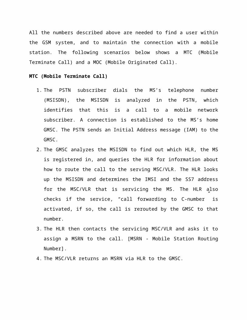
All the numbers described above are needed to find a user within the GSM system, and to
maintain the connection with a mobile station. The following scenarios below shows a MTC
(Mobile Terminate Call) and a MOC (Mobile Originated Call).
MTC (Mobile Terminate Call)
1. The PSTN subscriber dials the MS’s telephone number (MSISDN), the MSISDN is
analyzed in the PSTN, which identifies that this is a call to a mobile network subscriber.
A connection is established to the MS’s home GMSC. The PSTN sends an Initial
Address message (IAM) to the GMSC.
2. The GMSC analyzes the MSISDN to find out which HLR, the MS is registered in, and
queries the HLR for information about how to route the call to the serving MSC/VLR.
The HLR looks up the MSISDN and determines the IMSI and the SS7 address for the
MSC/VLR that is servicing the MS. The HLR also checks if the service, “call forwarding
to C-number” is activated, if so, the call is rerouted by the GMSC to that number.
3. The HLR then contacts the servicing MSC/VLR and asks it to assign a MSRN to the call.
[MSRN - Mobile Station Routing Number].
4. The MSC/VLR returns an MSRN via HLR to the GMSC.
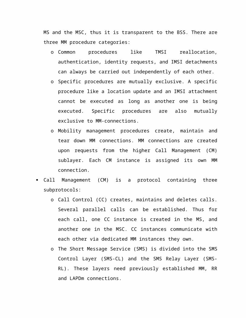
Fig: MTC (Mobile Terminate Call)
5. The GMSC sends an Initial Addressing message (IAM) to the servicing MSC/VLR and
uses the MSRN to route the call to the MSC/VLR. Once the servicing MSC/VLR
receives the call, the MSRN can be released and may be made available for reassignment.
6. The MSC/VLR then orders all of its BSCs and BTSs to page the MS. Since the
MSC/VLR does not know exactly which BSC and BTS the MS is monitoring, the page
will be sent out across the entire Location Area(LA).
7. When the MS detects the paging message to the BTS’s in the desired LA. The BTS’s
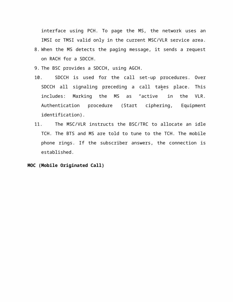
transmit the message over the air interface using PCH. To page the MS, the network uses
an IMSI or TMSI valid only in the current MSC/VLR service area.
8. When the MS detects the paging message, it sends a request on RACH for a SDCCH.
9. The BSC provides a SDCCH, using AGCH.

10. SDCCH is used for the call set-up procedures. Over SDCCH all signaling preceding a
call takes place. This includes: Marking the MS as “active” in the VLR. Authentication
procedure (Start ciphering, Equipment identification).
11. The MSC/VLR instructs the BSC/TRC to allocate an idle TCH. The BTS and MS are
told to tune to the TCH. The mobile phone rings. If the subscriber answers, the
connection is established.
MOC (Mobile Originated Call)
Fig: MOC (Mobile Originated Call)
It is much simpler to perform a mobile originated call(MOC) compared to a MTC. The MS
transmits a request for new connection(1), the BSS forwards this request to MSC(2). The MSC
then checks if this user is allowed to set up a call with requested service(3 and 4) and checks if
the availability of resources through the GSM network and into the PSTN. If all resources are
available, the MSC sets up a connection between the MS and fixed network.

In addition to the steps mentioned above, other messages are exchanged between MS and BTS as
shown in following figure.
Fig: Other messages are exchanged between MS and BTS
GSM Handover
Handover is the procedure that transfers an ongoing call from onecell to another as the user’s
moves through the coverage area of cellular system. The purpose of the handover procedure it to
preserve ongoing calls when the mobile station moving from one cell to another. In GSM

measurements reports to perform the handover, which is made by the serving BSC which has no
direct knowledge of the radio quality. These measurements reports contain the radio signal
quality of the downlink from the BTS to MSC of the call and up to five neighboring cells. The
serving BTS measures the uplink from the MSC to BTS radio signal quality of the call and
forward in the measurements reports. The information in the measurements reports the BSC is
able to decide whether a handover to another cell is needed. These measurements reports are
periodically transmitted from the MSC to BSC on the SACCH channel assigned to each
communication for every connection. Handover initiation is the process of deciding when a
request to a handover. Handover is based on received signal strength (RSS) from the current base
station and the neighboring base station.
There are different categories of GSM handover which involves different parts of the GSM
network. Changing cells within the same BTS is not complicated as the changing of the cell
belonging to different MSC. There are mainly two reasons for this kind of handover. The mobile
station moves out of the range station or the antenna of BTS respectively. Secondly the wire
infrastructure the MSC or the BSC may decide that the traffic in one cell is too high and move
some to other cells with lower load. These are the main reasons that initiate different kinds of
handover. Following are the different kinds of handover and their details.
Fig: Handovers in GSM
1. Intra-cell BTS Handover:
The terms intra-cell and intra BTS handover are used both for frequency change. There is
a slight between them but usually they are considered the same. The term intra-cell
handover in not real as it deals with the frequency change of a going call. The frequency
change occur when the quality of the communication link degrading and the
measurements of the neighboring cells better than the current cell. In this situation the
BSC which controls the BTS serving the MSC order the MSC and BTS to switch to
another frequency which offers better communication link for the call. The
communication link degradation is caused by the interference as the neighboring cell
using the same frequencies and its better to try another channel. In the intra BTS
handover cell involved are synchronized.
2. Intra-BSC Handover:
The intra-BSC handover is performed when the MSC changes the BTS but not the BSC.
The intra BBSC handover is entirely carried out by the BSC, but the MSC is notified
when the handover has taken place. If the targeted cell is in different location area then
the MSC needs to perform the location updates procedure after the call. In the intra-BSC
handover both synchronized and non synchronized handover are possible.
3. Intra-MSC Handover:
In the intra-MSC handover when the BSC decides that handover is required but the
targeted cell is controlled by different BSC then it needs assistance form the connected
MSC. In comparison to the pervious handover discussed the MSC mandatory for this
kind of handover. Responsibilities of the MSC do not include processing the
measurements of the BTS or MSC but to conclude the handover. This kind of handover
can be other intra-MSC or Inter-MSC. In the intra-MSC handover the targeted cell is
allocate in different BSC connected by the same MSC. The MSC contacts the targeted
BSC for allocation of the required resources and inform the BSC when they are ready.
After the successful resources allocation the MSC instructed to access the new channel
and the call is transferred to the new BSC.

4. Inter-MSC Handover:
The inter-MSC handover is performed when the two cells belonging to different MSC in
the same system. In the inter-MSC handover the targeted cell is connected is connected to
different MSC than the one currently serving the call MSC.
GSM Security
The security methods standardized for the GSM System make it the most secure cellular
telecommunications standard currently available. Although the confidentiality of a call and
anonymity of the GSM subscriber is only guaranteed on the radio channel, this is a major step in
achieving end-to- end security.
The subscriber's anonymity is ensured through the use of temporary identification numbers. The
confidentiality of the communication itself on the radio link is performed by the application of
encryption algorithms and frequency hopping which could only be realized using digital systems
and signaling.
Mobile Station Authentication:
The GSM network authenticates the identity of the subscriber through the use of a
challenge-response mechanism. A 128-bit random number (RAND) is sent to the MS.
The MS computes the 32-bit signed response (SRES) based on the encryption of the
random number (RAND) with the authentication algorithm (A3) using the individual
subscriber authentication key (Ki). Upon receiving the signed response (SRES) from the
subscriber, the GSM network repeats the calculation to verify the identity of the
subscriber.
The calculation of the signed response is processed within the SIM. This provides
enhanced security, because the confidential subscriber information such as the IMSI or
the individual subscriber authentication key (Ki) is never released from the SIM during
the authentication process.
Signaling and Data Confidentiality:
The SIM contains the ciphering key generating algorithm (A8) which is used to produce
the 64-bit ciphering key (Kc). The ciphering key is computed by applying the same
random number (RAND) used in the authentication process to the ciphering key
generating algorithm (A8) with the individual subscriber authentication key (Ki). As will
be shown in later sections, the ciphering key (Kc) is used to encrypt and decrypt the data
between the MS and BS.
An additional level of security is provided by having the means to change the ciphering
key, making the system more resistant to eavesdropping. The ciphering key may be
changed at regular intervals as required by network design and security considerations. In
a similar manner to the authentication process, the computation of the ciphering key (Kc)
takes place internally within the SIM. Therefore sensitive information such as the
individual subscriber authentication key (Ki) is never revealed by the SIM.
Encrypted voice and data communications between the MS and the network is
accomplished through use of the ciphering algorithm A5. Encrypted communication is
initiated by a ciphering mode request command from the GSM network. Upon receipt of
this command, the mobile station begins encryption and decryption of data using the
ciphering algorithm (A5) and the ciphering key (Kc).
Subscriber Identity Confidentiality:
To ensure subscriber identity confidentiality, the Temporary Mobile Subscriber Identity
(TMSI) is used. The TMSI is sent to the mobile station after the authentication and
encryption procedures have taken place. The mobile station responds by confirming
reception of the TMSI. The TMSI is valid in the location area in which it was issued. For
communications outside the location area, the Location Area Identification (LAI) is
necessary in addition to the TMSI.
Conclusion: Hence we studied GSM model, its architecture, protocol stack, calling and
localization and security.