Combustion and Flame - KAISTprocom.kaist.ac.kr/Download/IJP/151.pdf · Combustion and Flame 173...
8
Combustion and Flame 173 (2016) 106–113 Contents lists available at ScienceDirect Combustion and Flame journal homepage: www.elsevier.com/locate/combustflame Ignition characteristics of kerosene droplets with the addition of aluminum nanoparticles at elevated temperature and pressure Dong Min Kim, Seung Wook Baek ∗ , Jisu Yoon Department of Aerospace Engineering, School of Mechanical and Aerospace Engineering, Korea Advanced Institute of Science and Technology (KAIST), 291 Daehak-ro, Yuseong-gu, Daejeon 305-701, Republic of Korea a r t i c l e i n f o Article history: Received 27 February 2016 Revised 26 July 2016 Accepted 27 July 2016 Keywords: Ignition High pressure High temperature Kerosene droplet Aluminum nano-particles a b s t r a c t The effects of various ambient pressure and temperature conditions on the ignition characteristics of kerosene-based nanofluid droplets were investigated experimentally. Individual kerosene droplet contain- ing 0.1 or 1% by mass was mounted on the tip of silicon carbide (SiC) fiber and exposed to ambient temperatures in the range of 400–700 °C and ambient pressures in the range of 0.1–2.5 MPa under nor- mal gravity. An increase in ambient pressure was observed to reduce the ignition location distance below a droplet. The ignition delay times of pure kerosene droplets were also examined for comparison. The results showed that the ignition delay time of Al NPs-laden kerosene droplets decreased exponentially with increasing temperature, as did that of pure kerosene droplets. An ambient pressure increase from 0.1 to 2.5 MPa led to a decrease in the lowest ambient temperature for ignition from 800 to 400 °C. At pressures greater than 1 MPa, the ignition delay times of droplets with 1% Al were shorter than those of pure kerosene and kerosene with 0.1% Al. Furthermore, as the ambient pressure increased from 0.1 to 2.5 MPa, the ignition delay was found to decrease and then increase exceeding the limiting pressure. © 2016 The Combustion Institute. Published by Elsevier Inc. All rights reserved. 1. Introduction Purposely designed high-energy-density fuels are a compelling need for future combustion and propulsion systems. The energy density of available conventional fuels is sometimes a major lim- iting factor for current liquid propulsion systems. Therefore, there is an enormous need to enhance the energy density of both tra- ditional and new synthetic fuels. The volumetric energy contents of metals are normally higher than the energy densities of con- ventional liquid fuels so that higher combustion energies can be achieved using metallized liquid fuels. Because of this advantage that metallized liquid fuels offer, many researchers have conducted research on slurry fuels, in which micron-sized metallic particles are suspended in liquid hydrocarbon fuels. The major disadvan- tages that limit the practical application of such fuels are incom- plete combustion, undesirable deposits of particle in the combus- tion chamber and increased particle emissions in exhaust. Particle agglomeration and longer burning time are the primary causes of these defects [1]. Nanofluid fuels are a stable suspension of energetic nanoparti- cles (NPs) mixed with conventional liquid fuels. Various types of ∗ Corresponding author. E-mail address: [email protected] (S.W. Baek). nano-sized energetic materials have been used as additives and suspended in traditional liquid fuels for the purpose of enhancing their ignition and combustion characteristics. The sizes of agglom- erates should be reduced in dealing with nanometer-sized parti- cles. Van Devener and Anderson [2] reported a catalytic combus- tion of JP-10 at atmospheric pressure, using nanoparticulate CeO 2 as the catalyst. A substantial reduction in the ignition temperature was observed. Hot plate ignition probability measurements were carried out at atmospheric pressure on various volume fractions of aluminum/diesel mixtures and aluminum-oxide/diesel mixtures. The ignition probability of the nanoparticles/diesel mixtures was observed to be much higher than that of pure diesel [3]. The ef- fect of nanoscale Al particle addition on the combustion charac- teristics of gelled nitromethane was explored from both a deto- nation and deflagration perspective using an optical pressure ves- sel up to 14.2 MPa [4]. The impact of energetic Al nanoparticles on reducing the ignition delay of ethanol and JP-8 was presented by Allen et al. The autoignition delay was measured for neat and Al nanoparticle-enhanced mixtures at compressed conditions of 772– 830 K and 12–28 bar in the RCM [5]. The heat of combustion of n- Al and n-Al 2 O 3 in ethanol was investigated using a modified static bomb calorimeter system [6]. A detailed understanding of the vaporization and ignition char- acteristics of an isolated droplet is essential to understanding the operation of various practical liquid fuel combustion systems. http://dx.doi.org/10.1016/j.combustflame.2016.07.033 0010-2180/© 2016 The Combustion Institute. Published by Elsevier Inc. All rights reserved.
Transcript of Combustion and Flame - KAISTprocom.kaist.ac.kr/Download/IJP/151.pdf · Combustion and Flame 173...

Combustion and Flame 173 (2016) 106–113
Contents lists available at ScienceDirect
Combustion and Flame
journal homepage: www.elsevier.com/locate/combustflame
Ignition characteristics of kerosene droplets with the addition of
aluminum nanoparticles at elevated temperature and pressure
Dong Min Kim, Seung Wook Baek
∗, Jisu Yoon
Department of Aerospace Engineering, School of Mechanical and Aerospace Engineering, Korea Advanced Institute of Science and Technology (KAIST), 291
Daehak-ro, Yuseong-gu, Daejeon 305-701, Republic of Korea
a r t i c l e i n f o
Article history:
Received 27 February 2016
Revised 26 July 2016
Accepted 27 July 2016
Keywords:
Ignition
High pressure
High temperature
Kerosene droplet
Aluminum nano-particles
a b s t r a c t
The effects of various ambient pressure and temperature conditions on the ignition characteristics of
kerosene-based nanofluid droplets were investigated experimentally. Individual kerosene droplet contain-
ing 0.1 or 1% by mass was mounted on the tip of silicon carbide (SiC) fiber and exposed to ambient
temperatures in the range of 40 0–70 0 °C and ambient pressures in the range of 0.1–2.5 MPa under nor-
mal gravity. An increase in ambient pressure was observed to reduce the ignition location distance below
a droplet. The ignition delay times of pure kerosene droplets were also examined for comparison. The
results showed that the ignition delay time of Al NPs-laden kerosene droplets decreased exponentially
with increasing temperature, as did that of pure kerosene droplets. An ambient pressure increase from
0.1 to 2.5 MPa led to a decrease in the lowest ambient temperature for ignition from 800 to 400 °C. At
pressures greater than 1 MPa, the ignition delay times of droplets with 1% Al were shorter than those
of pure kerosene and kerosene with 0.1% Al. Furthermore, as the ambient pressure increased from 0.1 to
2.5 MPa, the ignition delay was found to decrease and then increase exceeding the limiting pressure.
© 2016 The Combustion Institute. Published by Elsevier Inc. All rights reserved.
n
s
t
e
c
t
a
w
c
o
T
o
f
t
n
s
r
A
n
8
A
1. Introduction
Purposely designed high-energy-density fuels are a compelling
need for future combustion and propulsion systems. The energy
density of available conventional fuels is sometimes a major lim-
iting factor for current liquid propulsion systems. Therefore, there
is an enormous need to enhance the energy density of both tra-
ditional and new synthetic fuels. The volumetric energy contents
of metals are normally higher than the energy densities of con-
ventional liquid fuels so that higher combustion energies can be
achieved using metallized liquid fuels. Because of this advantage
that metallized liquid fuels offer, many researchers have conducted
research on slurry fuels, in which micron-sized metallic particles
are suspended in liquid hydrocarbon fuels. The major disadvan-
tages that limit the practical application of such fuels are incom-
plete combustion, undesirable deposits of particle in the combus-
tion chamber and increased particle emissions in exhaust. Particle
agglomeration and longer burning time are the primary causes of
these defects [1] .
Nanofluid fuels are a stable suspension of energetic nanoparti-
cles (NPs) mixed with conventional liquid fuels. Various types of
∗ Corresponding author.
E-mail address: [email protected] (S.W. Baek).
b
a
t
http://dx.doi.org/10.1016/j.combustflame.2016.07.033
0010-2180/© 2016 The Combustion Institute. Published by Elsevier Inc. All rights reserved
ano-sized energetic materials have been used as additives and
uspended in traditional liquid fuels for the purpose of enhancing
heir ignition and combustion characteristics. The sizes of agglom-
rates should be reduced in dealing with nanometer-sized parti-
les. Van Devener and Anderson [2] reported a catalytic combus-
ion of JP-10 at atmospheric pressure, using nanoparticulate CeO 2
s the catalyst. A substantial reduction in the ignition temperature
as observed. Hot plate ignition probability measurements were
arried out at atmospheric pressure on various volume fractions
f aluminum/diesel mixtures and aluminum-oxide/diesel mixtures.
he ignition probability of the nanoparticles/diesel mixtures was
bserved to be much higher than that of pure diesel [3] . The ef-
ect of nanoscale Al particle addition on the combustion charac-
eristics of gelled nitromethane was explored from both a deto-
ation and deflagration perspective using an optical pressure ves-
el up to 14.2 MPa [4] . The impact of energetic Al nanoparticles on
educing the ignition delay of ethanol and JP-8 was presented by
llen et al. The autoignition delay was measured for neat and Al
anoparticle-enhanced mixtures at compressed conditions of 772–
30 K and 12–28 bar in the RCM [5] . The heat of combustion of n-
l and n-Al 2 O 3 in ethanol was investigated using a modified static
omb calorimeter system [6] .
A detailed understanding of the vaporization and ignition char-
cteristics of an isolated droplet is essential to understanding
he operation of various practical liquid fuel combustion systems.
.

D.M. Kim et al. / Combustion and Flame 173 (2016) 106–113 107
I
e
t
n
c
o
e
a
a
d
t
[
i
c
T
t
b
p
g
Q
f
s
b
a
A
e
J
p
J
t
l
o
N
l
h
e
t
n
e
[
2
2
t
f
v
(
k
S
d
u
l
b
N
t
o
p
T
w
m
I
Fig. 1. Schematic of the experimental setup: (1) pressure vessel, (2) guide bar,
(3) furnace entrance, (4) electric furnace, (5) quartz glass window on furnace,
(6) temperature controller, (7) furnace lever, (8) nitrogen vessel, (9) quartz glass
window on pressure vessel, (10) light source, (11) Si–C fiber, (12) droplet, (13)
shock absorber, (14) droplet maker, (15) plunger micro pump, and (16) high-speed
camera.
m
A
w
2
a
v
s
a
s
d
e
n
p
T
p
d
a
t
t
w
s
t
0
i
gnition of an individual droplet is considered a classical subject,
xamination of which provides the opportunity to explore the in-
eractions of the physical and chemical processes involved. The ig-
ition of a nanofluid fuel droplet is a highly complex phenomenon
ompared with the ignition of a pure liquid fuel droplet because
f its multi-component, multi-phase and multi-scale nature. Sev-
ral physical and chemical processes occur during the ignition of
nanofluid fuel droplet. These processes are made up of mass
nd energy transport between phases and microexplosions. In ad-
ition, the thermo-physical properties of nanofluid fuels such as
heir thermal conductivity [8] , mass diffusivity [9] , surface tension
10] , and radiative properties [11,12] , introduce additional complex-
ty. Furthermore, these properties can vary with time because of
ontinual change in the concentration of NPs within a droplet.
herefore, experimental studies, which are very rare, are required
o obtain a basic understanding of the vaporization and ignition
ehaviors of nanofluid fuel droplets.
Sabourin et al . [13] examined the burning rate of monopro-
ellant nitromethane through the addition of 1% functionalized
raphene sheets, which reduced its ignition temperature. Gan and
iao [14] observed the burning behavior of ethanol and n-decane
uel droplets by loading nano and micro-sized Al particles at atmo-
pheric pressure. Gan et al. [15] examined the simultaneous com-
ustion of dilute suspensions of boron and iron NPs in n-decane
nd ethanol. Recently, the intense disruptive burning behavior of
l NP-laden heptane droplets, which is characterized by multiple
xpansions and ruptures or microexplosions, was investigated by
aved et al. [16] . Because of these intense and frequent microex-
losions, almost no residue from Al NPs remained on the fiber.
aved et al. [17] also reported that the addition of dilute concen-
rations of Al NPs to kerosene droplets reduced the ignition de-
ay time while lowering the ignition temperature. However, most
f these previous studies were conducted at atmospheric pressure.
o previous research has been reported on the effects of the NP-
oading rate on droplet evaporation and ignition behavior under
ot stagnant air in furnace at elevated pressure conditions.
The goal of this study was to enhance the understanding of the
ffects of the addition of Al NPs to liquid kerosene fuel on its igni-
ion characteristics at elevated pressures and temperatures under
ormal gravity. The ignition behavior of pure kerosene was also
xamined for comparison. Kerosene was adopted as the base fuel
18] , and Al NPs were selected as energetic additives.
. Experimental setup
.1. Preparation of stable nanofluid fuels
This study began with the investigation of the physical methods
o be used to prepare homogeneous, stable, and durable nanofluid
uels. Stable kerosene-based nanofluid fuels were prepared with
arious concentrations of NPs using a two-step method. Al NPs
70 nm) were purchased from US Research Nanomaterials, Inc., and
erosene was purchased from JUNSEI (CAS NUMBER 8008-20-06).
urface modification was applied to the Al NPs to improve their
ispersion stability in kerosene. Oleic acid (OA) was selected for
se in surface coating of the Al NPs because of its low molecu-
ar weight and its boiling point of 360 °C, which is close to the
oiling point of the base fuel (180–270 °C). The surfaces of the
Ps were coated with OA using a planetary ball mill (PM100) so
hat oxide-free, ligand-protected and fuel-soluble Al NPs could be
btained [19–20] . An ultrasonic disruptor was then used to dis-
erse particles evenly in kerosene while avoiding agglomeration.
he sonicator, which generates a series of 5-s-long pulses 5 s apart,
as turned on for 20 min. The ratio of Al NPs to OA was opti-
ized at 2:1 in to obtain stable suspensions of NPs in kerosene.
n this manner, a homogeneous suspension was obtained, and re-
ained stable for 2 hours without sedimentation of the NPs. These
l/OA mixtures were blended in two proportions (0.1% and 1%)
ith kerosene.
.2. Experimental apparatus and procedure
The experimental apparatus used here was designed, fabricated
nd installed by our group in past and discussed in detail in pre-
ious studies [7,16,17,21–24] . The experimental procedure was de-
cribed in detail in Javed et al. [17] , along with the data reduction
nd analysis. A schematic view of the experimental apparatus is
hown in Fig. 1 . A droplet hanging on a fine SiC fiber (100 μm in
iameter) is subjected to a hot air environment by a freely falling
lectric furnace, resulting in combustion. This ignition unit with in-
er dimensions of 0.065 m ×0.065 m ×0.12 m is enclosed within a
ressure vessel with height of 0.8 m and inner diameter of 0.15 m.
wo glass windows with 0.05 m ×0.04 m ×0.01 m are installed to
ermit observation of the droplet ignition process. In order to re-
uce the time for gas temperature to rise before falling of furnace
nd to prevent the droplet from being preheated by the furnace,
he falling distance should be long. However, a long travel dis-
ance of the furnace would induce a strong impact on the base
hen it falls. The falling distance is set about 0.4 m in the present
tudy to satisfy the above requirements. Based on this design, this
ravel distance provides a droplet with entering time shorter than
.5 s. Impact shock due to collision of the furnace with bottom wall
s relieved by placing a couple of shock absorbers at the impact

108 D.M. Kim et al. / Combustion and Flame 173 (2016) 106–113
m
t
e
f
c
n
o
m
p
m
d
s
o
m
d
n
h
a
m
d
l
t
c
h
k
n
t
c
s
d
p
s
l
i
i
1
a
a
o
b
t
3
A
o
p
r
o
A
r
d
i
s
c
w
t
a
k
t
n
1
location, so that the droplet should remain stable. In order to pro-
duce a droplet around the bead at the tip of the SiC fiber, an injec-
tion system is installed. It produces a droplet as small as 1 mm in
diameter. It consists of a stainless steel pipe, micro needle, micro
pump and a lever as shown below and operates quite well even
at high-pressure environments. The needle is connected to the mi-
cro pump through a fine capillary tube. The movement of needle
is provided by a lever on which needle is mounted. The lever can
carry the needle very close to the suspended fiber by vertical dis-
placement and then, the liquid fuel is transferred to the bead by
turning the lever, thereby generating a droplet.
The burning process was observed using a high-speed camera
(operating at a rate of 200 frames per second). A single droplet
was suspended using a SiC fiber. The initial average diameter of
a droplet was approximately 1.0 ± 0.1 mm. Dry air was used as an
oxidizer for ignition. The ambient pressure was varied within the
range 0.1–2.5 MPa, and the ambient temperature was varied within
the range of 40 0–70 0 °C, which is higher than the ignition tem-
perature of kerosene (220 °C). Because a thin SiC fiber was used
for droplet suspension, the heat transfer between the droplet and
the fiber was minimized. The ignition delay time is defined as the
time to ignition, starting from the time at which a droplet of liq-
uid fuel is introduced into the hot air environment. Ignition is vi-
sually detected by the appearance of a visible flame, using high-
speed color photography. For each ignition data point, measure-
ments were taken at least five times to ensure reproducibility and
consistency. Average values were determined and displayed with
error bars that indicate the maximum and minimum values of the
data obtained. The variations around the average values resulted
mainly from the uncertainties associated with the temperature and
droplet diameter.
A flexible image-processing method was developed using the
Fortran language to obtain the droplet diameter. The procedure for
calculating the droplet diameter from the captured images was de-
scribed in our previous study [21–24] . Briefly, in this method, a
threshold value for the pixel gray level was carefully set to count
the pixels in the droplet zone. Then, the area of a circle having the
same number of pixels, which the droplet actually represents, is
calculated. This way in turn yields the droplet diameter using the
law of proportions with reference to the diameter of a SiC fiber
(100 μm). In some cases, the droplet is distorted during the ignition
process. However, using this approach, the diameter of an irregu-
larly shaped droplet can be calculated with reasonable accuracy.
This method was executed iteratively for each image to determine
the temporal variation of the droplet diameter during the ignition
process.
3. Results and discussion
3.1. Droplet ignition
Typical ignition characteristics may be described in terms of
the ignition delay which is determined as a function of the initial
ambient gas temperature. The effects of other variables including
the pressure, equivalence ratio, droplet size, and fuel type, may be
included via parametric investigation. The ignition delay was de-
fined as the time interval from the instant at which the droplet
was exposed to the high-temperature environment to the instant
at which a visible flame was observed. When an isolated single
droplet with a certain initial temperature is suddenly exposed to
a high-temperature environment at a pressure in the range of 0.1–
2.5 MPa, vaporization starts on the droplet surface after an initial
heating-up period.
The fuel vapors generated are diffused radially outward and
downward as time passes, because kerosene vapor is heavier than
air, while mixing with air in the ambience. When a fuel vapor-air
ixture of appropriate proportion is produced and the fuel activa-
ion energy is overcome, ignition takes place. The time lag between
xposure to a high temperature and when a sufficient amount of
uel vapor has been produced for ignition to occur is the physi-
al delay. The time lapse between when a sufficient amount of ig-
itable fuel vapor is available and when the activation energy is
vercome is the chemical delay. Note that in the ignition of a ho-
ogeneous mixture of a fuel and an oxidizer, there is almost no
hysical delay, unlike in the case of an inhomogeneous mixture, as
ixing of the fuel and air is not required. Therefore, the ignition
elay associated with premixed gaseous mixtures is significantly
horter than associated with non-premixed cases under the same
perating conditions. In other words, the ignition delay for a pre-
ixed fuel and oxidizer consists almost entirely of the chemical
elay.
The experimental apparatus used in this study is based on a
on-premixed configuration, so the ignition delay times described
ere should only be compared with the other data obtained using
similar experimental arrangement. These data provide a funda-
ental understanding of the overall ignition characteristics of fuel
roplets, which are important in the optimal design of practical
iquid–fuel combustors. The experimental apparatus employed in
his study is relatively easy to use and is appropriate for use in a
omparative study of the effects of the addition of NPs to a liquid
ydrocarbon fuel on the fuel’s overall ignition characteristics. The
erosene used as the fuel in this study is a complex multicompo-
ent fuel. Vaporization of the various components affects the igni-
ion process and makes it completely different than that of single-
omponent hydrocarbon fuels.
The effects of the addition of dilute concentrations of nano-
ized Al particles on the ignition characteristics of kerosene
roplets were investigated at various elevated temperatures and
ressures. The ignition delay time of pure kerosene droplets was
tudied first as a baseline for comparison with others. This al-
owed us to investigate the effects of the addition of NPs on the
gnition behavior of kerosene-based nanofluid fuel droplets. The
nitial diameter of the droplets was selected to be approximately
.0 ± 0.1 mm to minimize the effects of variation in the droplet di-
meter on the ignition delay. The ignition delay time was defined
s the time from the entry of the droplet into the furnace to the
nset of ignition. The occurrence of ignition was visually identified
y the appearance of a visible flame, using high-speed color pho-
ography.
.2. Ignition delays for various ambient pressures
Figure 2 (a)–(f) compares the ignition delay times of n-
l/kerosene droplets containing dilute concentrations (0.1% and 1%)
f Al NPs with those of pure kerosene droplets for various ambient
ressure conditions. The ignition delay time is plotted on a loga-
ithmic scale against the inverse ambient temperature. This type
f representation is usually adopted for the case directed by the
rrhenius rate law. The activation energy of the system can be de-
ived from the slope of the line. The ignition delay time is normally
ependent on the chemistry of the ignition as well as on the phys-
cal process of droplet heating. Nonetheless, the ignition delay data
till lie on a straight line for the range of experimental conditions
onsidered.
At atmospheric pressure, the ignition of a pure kerosene droplet
as not observed in the atmospheric pressure ambient tempera-
ure range from 400 to 700 °C, whereas ignition occurred at 800 °Cs shown in Fig. 2 (a). Even when Al NPs were added to the
erosene, ignition did not take place at atmospheric pressure at
emperatures within the range of 400 to 700 °C. At 800 °C the ig-
ition delay for the pure kerosene droplet was observed to be
s, while it is 1.16 s for 0.1% addition of Al NPs and 1.09 s for

D.M. Kim et al. / Combustion and Flame 173 (2016) 106–113 109
Fig. 2. Comparison of ignition delay time of n-Al/kerosene droplets containing dilute concentrations (0.1% and 1%) of Al NPs with those of pure kerosene droplets for various
ambient pressure conditions.

110 D.M. Kim et al. / Combustion and Flame 173 (2016) 106–113
d
i
t
t
F
s
A
t
s
t
i
t
t
h
f
p
1.0% addition of Al NPs. These results show that the addition of
Al NPs leads to a slight increase in ignition delay at atmospheric
pressure. A comparison of Fig. 2 (a) with Fig. 2 (b)–(d) shows that
n-Al/kerosene droplets and pure kerosene droplets are ignited at
temperatures between 500 and 700 °C when the pressure is in the
range of 0.5 and 1.5 MPa, but they are not ignited at 400 °C. Fur-
thermore, as seen in Fig. 2 (e) and (f), both n-Al/kerosene droplets
and pure kerosene droplets are ignited at temperatures between
40 0 and 70 0 °C when the pressure is between 2.0 and 2.5 MPa.
These findings suggest that the minimum ambient temperature for
onset of ignition was lowered from 800 to 400 °C, as the ambi-
ent pressure increased from 0.1 to 2.5 MPa. The autoignition tem-
perature of bulk kerosene fuel is listed as 220 °C, according to the
manufacturer. Because the ambient density also increases as the
ambient pressure increases, the kerosene fuel vapors experience a
diffusional resistance in outward mass diffusion at higher ambient
pressures, which increases the residence time of the fuel vapor and
hence increases the Damkohler number, which is the ratio of mass
transfer time to characteristic chemical reaction time. o
Fig. 3. Comparison of ignition delay times of n-Al/kerosene droplets containing 1% of Al
2.5 MPa and various ambient temperature conditions.
When the pressure increases to 0.5 MPa, the n-Al/kerosene
roplets are ignited faster than pure kerosene droplets as shown
n Fig. 2 (b). This is because the addition of Al particles enhances
he evaporation rate of kerosene, because of the increased effec-
ive thermal conductivity of the droplet.
For ambient pressures in the range of 1.0 MPa to 2.5 MPa in
ig. 2 (c)–(f), the ignition delay of 1.0% Al/kerosene droplets was
horter than the others, whereas the ignition delay of 0.1%
l/kerosene droplets was longer than the others. Higher effec-
ive thermal conductivity of the droplet with 1.0% Al nanoparticles
eemed to help transfer the heat energy from the environment to
he droplet. Although the kerosene in the droplet reaches its boil-
ng temperature of 180–270 °C together with the nanoparticles, af-
erwards the nanoparticle temperature increases even higher than
he kerosene boiling temperature. Thereby, nanoparticles become
eat supplier to the liquid phase. That is why the evaporation rate
or the case with 1.0% of Al nanoparticles is higher than those of
ure kerosene and 0.1% Al nanoparticles droplets. Consequently, its
verall 1.0% Al/kerosene droplet heating is enhanced in comparison
NPs with those of pure kerosene droplets for ambient pressures between 0.1 and

D.M. Kim et al. / Combustion and Flame 173 (2016) 106–113 111
t
O
N
1
r
d
p
3
s
t
t
o
o
i
A
p
4
e
t
a
i
d
f
4
0
t
n
p
(
e
n
t
a
d
a
a
t
c
s
d
a
i
3
p
i
i
a
o that of pure kerosene droplets, which leads to faster ignition.
n the other hand, in the case of 0.1% Al/kerosene droplets, Al
Ps are distributed sparsely inside the droplet, in comparison with
% Al/kerosene droplets, so Al NPs become heat absorber, which
etards its droplet heating in comparison with the pure kerosene
roplets. Therefore, 0.1% Al/kerosene droplets are ignited later than
ure kerosene droplets.
.3. Ignition delays for various ambient temperatures
The initial heating-up period of the n-Al/kerosene droplets was
horter than that of the pure kerosene droplets at higher tempera-
ure, regardless of the NP loadings because of the increased effec-
ive thermal conductivity of the droplet. The corresponding evap-
ration period of the n-Al/kerosene droplets was reduced because
f the increased evaporation rate. Figure 3 (a)–(d) shows a compar-
son of the ignition delays of n-Al/kerosene droplets containing 1%
l NP loading with that of pure kerosene droplets, as the ambient
ressure increases for ambient temperature conditions between
0 0 and 70 0 °C. For the range of temperature conditions consid-
red, the ignition delay of the droplets with 1% Al was shorter
han that of pure kerosene droplets in the pressure range of 0.5
nd 2.5 MPa. Both pure and n-Al/kerosene droplets experienced an
nitial heating-up period, followed by evaporation governed by the
2 -law. Droplets with 1% Al heated up more quickly, resulting in
aster evaporation and ignition. However, as shown in Fig. 3 (a) at
00 °C, neither type of droplets ignited at pressures in the range of
Fig. 4. Onset of ignition at 700 °C for various ambient pressure conditions. (a) Pure kero
.1 and 1.5 MPa. At 0.1 MPa, the onset of droplet ignition did not
ake place at temperatures up to 700 °C, whereas they were all ig-
ited at 800 °C at 0.1 MPa.
Figure 3 (a)–(d) illustrates a very interesting effect of ambient
ressure on the ignition delay. At 500 and 600 °C, as Fig. 3 (b) and
c) shows, the ignition delay is observed to decrease as the ambi-
nt pressure increased from 0.1 MPa to 1.0 MPa, neither pure nor
-Al/kerosene droplets ignited at all at 0.1 MPa, which means that
heir ignition delays were infinite. A decrease in the ignition delay,
s the ambient pressure increases, is considered to result from the
ecrease in the heat of vaporization of liquid. However, when the
mbient pressure increased further from 1.0 MPa to 2.5 MPa at 500
nd 600 °C, the ignition delay increased. This observed increase in
he ignition delay with increasing ambient pressure in excess of a
ertain limiting pressure was also observed at 400 and 700 °C as
hown in Fig. 3 (a) and (d), even though the rate of increase was
ifferent. The difficulty in diffusion and mixing of fuel vapor and
ir at higher pressure is the main reason for the increase in the
gnition delay.
.4. Effect of ambient pressure on ignition behavior
The ignition always began below the kerosene droplet as re-
orted by Ghassemi et al. [22] , because kerosene vapor is heav-
er than air and tends to fall downward. Whang et al. [25] stud-
ed the effect of the ambient temperature on the ignition location
nd distance from the droplet at atmospheric pressure. They found
sene, (b) kerosene + 0.05% OA + 0.1% Al NPs, (c) kerosene + 0.5% OA + 1.0% Al NPs.
112 D.M. Kim et al. / Combustion and Flame 173 (2016) 106–113
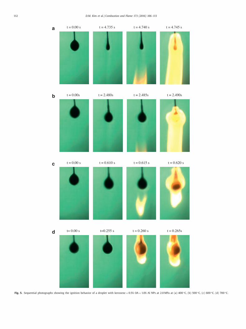
Fig. 5. Sequential photographs showing the ignition behavior of a droplet with kerosene + 0.5% OA + 1.0% Al NPs at 2.0 MPa at (a) 400 °C, (b) 500 °C, (c) 600 °C, (d) 700 °C.

D.M. Kim et al. / Combustion and Flame 173 (2016) 106–113 113
t
c
c
f
n
A
s
s
c
0
t
e
w
s
o
t
I
t
n
3
s
t
4
d
e
t
2
i
d
p
a
F
4
f
g
c
p
c
o
A
L
R
[
[
[
[
[
hat the distance between the droplet and the ignition location de-
reased as the ambient temperature increased because of an in-
rease in the Damkohler number.
In contrast to that study above, this study examined the ef-
ect of an ambient pressure range of 0.1 and 2.5 MPa on the ig-
ition location at the onset of ignition for pure kerosene and n-
l/kerosene droplets at 700 °C. Figure 4 (a)–(c) illustrates the re-
ults for pure kerosene, 0.1% Al/kerosene and 1% Al/kerosene, re-
pectively. These figures clearly show that the ignition takes place
loser to the droplet as the ambient pressure increases from
.5 to 2.0 MPa, regardless of the Al loadings. At 2.5 MPa, igni-
ion is even observed above the droplet. An increase in ambi-
nt pressure seems to increase the Damkohler number in two
ays. Because the ambient density increases as the ambient pres-
ure increases, kerosene vapor experiences resistance to radial
utward diffusion at high ambient pressures, which increases
he residence time and hence increases the Damkohler number.
n addition, an increase in the ambient pressure may decrease
he chemical reaction time and hence increases the Damkohler
umber.
.5. Effect of ambient temperature on ignition behavior
Figure 5 (a)–(d) presents typical sequential photographs that
how the ignition behavior for various ambient temperatures be-
ween 400 and 700 °C for 1.0% Al/kerosene droplets at 2.0 MPa. At
00 °C, as Fig. 5 (a) shows, the flame was initiated far below the
roplet at 4.74 s, at which time the kerosene droplet was almost
vaporated. The flame was then observed to propagate upward. On
he other hand, at 500 °C as Fig. 5 (b) shows, ignition occurred at
.485 s, at which time the droplet was evaporating. Consequently,
t can be deduced that the onset of ignition occurs closer to the
roplet as the ambient temperature increases. As the ambient tem-
erature decreases, the ignition occurs farther below the droplets,
nd the flame propagates upward toward the droplet, as shown in
ig. 5 (a)–(c).
. Conclusions
In this study, the ignition behaviors of individual kerosene
uel droplet with different concentrations of Al NPs were investi-
ated experimentally at various ambient temperature and pressure
onditions. The main objective of this work was to gain an im-
roved understanding of the ignition characteristics of these multi-
omponent hydrocarbon-based nanofluid fuels. The major results
f this work can be summarized as follows.
1. Ignition is primarily controlled by the thermal time at low
temperatures of 400 °C whereas it is controlled by diffusion
and mixing time at higher temperatures between 500 and
700 °C.
2. The lowest ambient temperature for the onset of ignition de-
creases from 800 to 400 °C, as the ambient pressure increases
from 0.1 to 2.5 MPa.
3. At pressures greater than 1 MPa, the ignition delays of droplets
with 1% Al are shorter than those of droplets of pure kerosene
and those with 0.1% Al. The latter had the longest ignition
delays.
4. As the ambient pressure increases up to the limiting pressure,
the ignition delay decreases. However, the ignition delay in-
creases, as the ambient pressure increases beyond the limiting
pressure.
5. The ignition location distance from the droplet decreases as
the ambient pressure increases because of the increase in
Damkohler number.
cknowledgments
This work was supported by the RoKST&R Program funded by
ockheed Martin (Research Agreement P14-058 ).
eferences
[1] P. Roy Choudhury , Slurry fuels, Prog. Energy Combust. Sci. 18 (1992) 409–427 .
[2] B. Van Devener , S.L. Anderson , Breakdown and combustion of JP-10 fuel cat-
alyzed by nanoparticulate CeO 2 and Fe 2 O 3 , Energy Fuels 20 (2006) 1886–1894 .[3] H. Tyagi , P.E. Phelan , R. Prasher , R. Peck , T. Lee , J.R. Pacheco , P. Arentzen , In-
creased hot-plate ignition probability for nanoparticle-laden diesel fuel, NanoLett. 8 (2008) 1410–1416 .
[4] J.L. Sabourin , R.A. Yetter , B.W. Asay , J.M. Lloyd , V.E. Sanders , G.A. Risha , S.F. Son ,Effect of nano-aluminum and fumed silica particles on deflagration and deto-
nation of nitromethane, Propellants Explos. Pyrotech. 34 (2009) 385–393 .
[5] C. Allen , G. Mittal , C.J. Sung , E. Toulson , T. Lee , An aerosol rapid compressionmachine for studying energetic-nanoparticle-enhanced combustion of liquid
fuels, Proc. Combust. Inst. 33 (2011) 3367–3374 . [6] M. Jones , C. Li , A. Afjeh , G. Peterson , Experimental study of combustion char-
acteristics of nanoscale metal and metal oxide additives in biofuel (ethanol),Nanoscale Res. Lett. 6 (2011) 246 .
[7] I. Javed , S.W. Baek , K. Waheed , Effects of dense concentrations of aluminum
nanoparticles on evaporation behavior of kerosene droplet at elevated temper-atures: phenomenon of microexplosion, Exp.Therm. Fluid Sci. 56 (2014) 33–44 .
[8] X. Wang , X. Xu , S.U.S. Choi , Thermal conductivity of nanoparticle–fluid mix-ture, J. Thermophys. Heat Transf. 13 (1999) 474–480 .
[9] S. Krishnamurthy , P. Bhattacharya , P.E. Phelan , R.S. Prasher , Enhanced masstransport in nanofluids, Nano Lett. 6 (2006) 419–423 .
[10] R.H. Chen , T.X. Phuoc , D. Martello , Surface tension of evaporating nanofluiddroplets, Int. J. Heat Mass Transf. 54 (2011) 2459–2466 .
[11] H. Tyagi , P.E. Phelan , R.S. Prasher , Predicted efficiency of a nanofluid-based di-
rect absorption solar receiver, ASME Energy Sustainability Conference (2007),pp. 729–736 .
[12] Y. Gan , L. Qiao , Optical properties and radiation-enhanced evaporation ofnanofluid fuels containing carbon-based nanostructures, Energy Fuels 26
(2012) 4224–4230 . [13] J. Sabourin , D. Dabbs , R. Yetter , F. Dryer , I. Aksay , Functionalized graphene
sheet colloids for enhanced fuel/propellant combustion, ACS Nano 3 (2009)
3945–3954 . [14] Y. Gan , L. Qiao , Combustion characteristics of fuel droplets with addition
of nano and micron-sized aluminum particles, Combust. Flame 158 (2011)354–368 .
[15] Y. Gan , Y.S. Kim , L. Qiao , Combustion of nanofluid fuels with the addition ofboron and iron particles at dilute and dense concentrations, Combust. Flame
159 (2012) 1732–1740 .
[16] I. Javed , S.W. Baek , K. Waheed , Autoignition and combustion characteristicsof heptane droplets with the addition of aluminum nanoparticles at elevated
temperatures, Combust. Flame 162 (2015) 191–206 . [17] I. Javed , S.W. Baek , K. Waheed , Autoignition and combustion characteristics of
kerosene droplets with dilute concentrations of aluminum nanoparticles at el-evated temperatures, Combust. Flame 162 (2015) 774–787 .
[18] T. Edwards , Liquid fuels and propellants for aerospace propulsion: 1903–2003,
J. Propuls. Power 19 (2003) 1089–1107 . [19] W. Yu , H. Xie , A review on nanofluids: preparation, stability mechanisms, and
applications, J. Nanomater. 1 (2012) 1–17 . 20] B. Van Devener , J.P.L. Perez , J. Jankovich , S.L. Anderson , Oxide-free, catalyst–
coated, fuel-soluble, air-stable boron nanopowder as combined combustioncatalyst and high energy density fuel, Energy Fuels 23 (2009) 6111–6120 .
[21] H. Ghassemi , S.W. Baek , Q.S. Khan , Experimental study on binary droplet evap-
oration at elevated pressures and temperatures, Combust. Sci. Technol. 178(2006) 1031–1053 .
22] H. Ghassemi , S.W. Baek , Q.S. Khan , Experimental study on evaporation ofkerosene droplets at elevated pressures and temperatures, Combust. Sci. Tech-
nol. 178 (2006) 1669–1684 . 23] Q.S. Khan , S.W. Baek , H. Ghassemi , On the autoignition and combustion charac-
teristics of kerosene droplets at elevated pressure and temperature, Combust.
Sci. Technol. 179 (2007) 2437–2451 . 24] H. Ghassemi , S.W. Baek , Q.S. Khan , Experimental study on binary droplet evap-
oration at elevated pressure and temperature, 43rd Aerospace Sciences Meet-ing and Exhibit (2005) .
25] J.J. Whang , C.Y. Yukao , J.T. Ho , S.C. Wong , Experimental study of the ignition ofsingle droplets under forced convection, Combust. Flame 110 (1997) 366–376 .