CombiThermPlus - SPX FLOW Manual.pdf · CTP/US (1605) 1.0 CombiThermPlus ... and to ensure safe and...
87
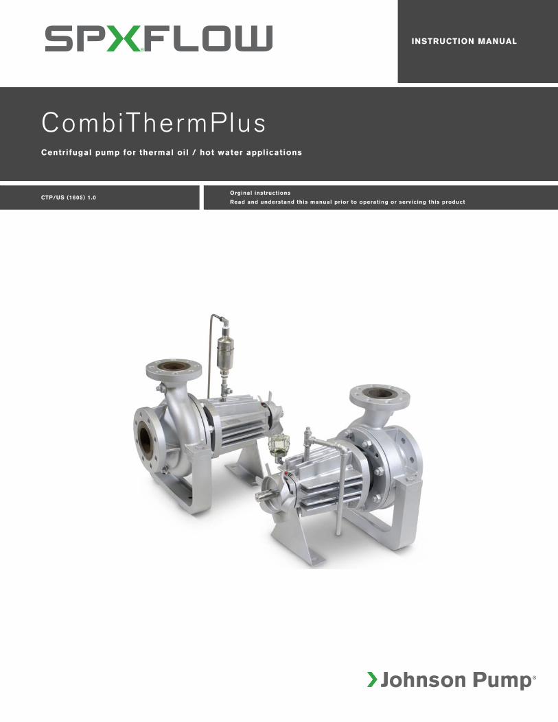
CTP/US (1605) 1.0 CombiThermPlus Orginal instructions Read and understand this manual prior to operating or servicing this product INSTRUCTION MANUAL Centrifugal pump for thermal oil / hot water applications
-
Upload
phungkhuong -
Category
Documents
-
view
217 -
download
0
Transcript of CombiThermPlus - SPX FLOW Manual.pdf · CTP/US (1605) 1.0 CombiThermPlus ... and to ensure safe and...
CTP/US (1605) 1.0
CombiThermPlus
Orginal instructions
Read and understand this manual prior to operating or servicing this product
INSTRUCTION MANUAL
Centrifugal pump for thermal oil / hot water applications

INT/US (1512) 1.2
Instruction manual
All technical and technological information in this manual as well as possible drawings made available by us remain our property and shall not be used (otherwise than for the operation of this pump), copied, duplicated, made available to or brought to the notice of third parties without our prior written consent.
SPXFLOW is a global multi-industry manufacturing leader. The company's highly-specialized, engineered products and innovative technologies are helping to meet rising global demand for electricity and processed foods and beverages, particularly in emerging markets.
Copyright © 2015 SPXFLOW Corporation
3

4
INT/US (1512) 1.2
CTP/US (1605) 1.0
CombiThermPlus
Table of Contents
1 Introduction 9
1.1 Preface 91.2 Warning 91.3 Safety 101.4 Guarantee 111.5 Inspection of delivered items 111.6 Instructions for transport and storage 111.6.1 Dimensions 111.6.2 Use of pallets 111.6.3 Hoisting 121.6.4 Storage 131.7 Long term storage 131.7.1 Storage 131.7.2 Putting into service after long term storage 131.8 Ordering parts 14
2 General 15
2.1 Pump description 152.2 Applications 152.3 Type code 162.4 Serial number 162.5 Construction 162.5.1 Pump casing / impeller 162.5.2 Shaft seal 172.5.3 Bearing 172.6 Application area 172.7 Re-use 172.8 Scrapping 17
3 Installation 19
3.1 Safety 193.2 Preservation 193.3 Environment 203.4 Piping 203.5 Accessories 213.6 Installation of a pump unit 21
5
6
3.7 Assembling a pump unit 213.8 Rexnord Omega Coupling 223.8.1 Elastomer element replacement 223.8.2 Installation 223.8.3 Alignment 233.9 Connection of the electric motor 243.10 Combustion engine 243.10.1 Safety 243.10.2 Sense of rotation 24
4 Commissioning 25
4.1 Pump start-up checklist 254.2 Inspection of the motor 264.3 Preparing the pump unit for commissioning 264.4 Checking the sense of rotation 274.5 Start-up 274.6 Pump in operation 274.7 Noise 27
5 Maintenance 29
5.1 Daily maintenance 295.2 Mechanical seal 295.3 Lubrication of the bearings 295.4 Environmental influences 305.5 Noise 305.6 Motor 305.7 Faults 30
6 Problem solving 31
7 Disassembly and assembly 33
7.1 Precautionary measures 337.2 Draining 337.3 Tools 347.4 Back-Pull-Out system 357.4.1 Disassembling the coupling guard 357.4.2 Disassembling the Back-Pull-Out unit 357.4.3 Assembling the Back-Pull-Out unit 357.4.4 Assembling the coupling guard 367.5 Disassembling the pump 367.6 Removing the pump cover 367.7 Removing the fan 367.8 Removing the bearing assembly 367.9 Replacing the impeller and the wear ring 387.9.1 Disassembling the impeller 387.9.2 Mounting the impeller 387.9.3 Disassembling the wear ring 407.9.4 Assembling the wear ring 407.10 Assembly instructions 417.10.1 Lubricants and sealants 417.10.2 Instructions for mounting a mechanical seal 41
CTP/US (1605) 1.0
CTP/US (1605) 1.0
CombiThermPlus
7.10.3 Instructions for assembly of bearings 417.11 Assembly 417.11.1 Installing the mechanical seal 417.11.2 Installing the bearings 427.11.3 Installing the journal bearing 437.11.4 Assembling the pump cover 437.11.5 Bearing bracket 437.11.6 Impeller 447.11.7 Assembling the pump 44
8 Dimensions 47
8.1 Dimensions thermal oil pump 488.1.1 Dimensions drawing 488.1.2 Connections 488.2 Dimensions hot water pump 508.2.1 Dimensions drawing 508.2.2 Connections 508.3 Dimensions thermal oil pump with motor 528.3.1 Dimension drawing 528.3.2 1750 RPM 538.3.3 3500 RPM 548.3.4 Base plate dimensions 548.4 Dimensions hot water pump with motor 558.4.1 Dimensions drawing 558.4.2 1750 RPM 568.4.3 3500 RPM 578.4.4 Base plate dimensions 578.5 Dimensions coupling guard 58
9 Parts 59
9.1 Ordering parts 599.1.1 Order form 599.1.2 Recommended spare parts 599.2 Thermal oil pump 609.2.1 Sectional drawing 609.2.2 Parts list 619.3 Hot water pump 639.3.1 Sectional drawing 639.3.2 Parts list 649.4 Cooling fan assembly 669.4.1 Sectional drawing 669.4.2 Parts list 669.5 Spare part kits 679.5.1 Impeller and wear ring replacement 679.5.2 Parts list impeller and wear ring replacement 679.5.3 Sealing kit thermal oil pump 689.5.4 Parts list sealing kit thermal oil pump 689.5.5 Sealing kit hot water pump 699.5.6 Parts list sealing kit hot water pump 699.5.7 Complete mechanical seal 709.5.8 Parts list complete mechanical seal 70
7
8
9.5.9 Mechanical seal O-rings kit 719.5.10 Parts list mechanical seal O-rings kit thermal oil pump 719.5.11 Parts list mechanical seal O-rings kit hot water pump 719.5.12 Ball bearings 729.5.13 Parts list ball bearings 729.5.14 Slide bearing replacement 739.5.15 Parts list slide bearing replacement 73
10 Technical data 75
10.1 Tightening torques 7510.1.1 Tightening torques for bolts and nuts. 7510.1.2 Tightening torques for cap nut 7510.2 Lubricants and sealants 7510.3 Maximum admissible working pressure 7610.4 Temperature dissipation in the pump 7610.5 Maximum speed 7710.6 Pressure near the impeller hub 7710.7 Permissible forces and moments on the flanges 7810.8 Hydraulic performance 8010.9 Noise data 8110.9.1 Pump noise as a function of pump power 8110.9.2 Noise level of entire pump unit 82
Index 83
CTP/US (1605) 1.0
CTP/US (1605) 1.0
CombiThermPlus
1 Introduction
1.1 Preface
This manual is intended for technicians and maintenance staff and for those who are in charge of ordering spare parts.
This manual contains important and useful information for the proper operation and maintenance of this pump. It also contains important instructions to prevent potential accidents and damage, and to ensure safe and fault-free operation of this pump.
! Read this manual carefully before commissioning the pump, familiarize yourself with the operation of the pump and strictly obey the instructions!
The data published here comply with the most recent information at the time of going to press. However they may be subject to later modifications.
SPXFLOW reserves the right to change the construction and design of the products at any time without being obliged to change earlier deliveries accordingly.
1.2 Warning
This equipment must be applied, installed, operated, and maintained by qualified personnel only, in strict accordance with the instruction manual and all applicable drawings and regulations, otherwise hazardous situations may occur.
Read the instruction manual completely before installing, filling, operating, or maintaining this equipment.
Read the MSDS (Material Safety Data Sheet) for the fluids being handled before attempting to fill, operate or maintain this equipment. Obtain instructions from the Safety Engineer responsible for your facility before performing any work on the pumping equipment and systems.
Proper storage while not in use and proper installation and startup are essential for successful pump operation. Misuse or improper storage, installation or operation of pumps may result in serious loss or damage. SPXFLOW is not responsible for any loss or damage resulting from causes beyond its control, and is not liable for charges for work performed or materials furnished to repair such loss or damage.
All installation, operation, and maintenance must be done by qualified personnel with proven experience in installing, operating and servicing rotating equipment, in strict accordance with this manual and must comply with all local and national directives. Only SPXFLOW authorized service parts must be used in the repair of these pumps.
Introduction 9
10
1.3 Safety
This manual contains instructions for working safely with the pump. Operators and maintenance staff must be familiar with these instructions.Installation, operation and maintenance has to be done by qualified and well prepared personnel.
Below is a list of the symbols used for those instructions and their meaning:
� Personal danger for the user. Strict and prompt observance of the corresponding instruction is imperative!
! Risk of damage or poor operation of the pump. Follow the corresponding instruction to avoid this risk.
➢ Useful instruction or tip for the user.
Items which require extra attention are shown in bold print.
This manual has been compiled by SPXFLOW with the utmost care. Nevertheless SPXFLOW cannot guarantee the completeness of this information and therefore assumes no liability for possible deficiencies in this manual. The buyer/user shall at all times be responsible for testing the information and for taking any additional and/or deviating safety measures. SPXFLOW reserves the right to change safety instructions.
SPXFLOW pumps are subject to thorough quality control and inspection procedures throughout the entire manufacturing process. This assures proper and reliable operation, fully compliant with established performance standards. Prior to shipment each pump is sprayed internally with rust inhibitor (if material is subject to atmospheric corrosion) and sealed against the entrance of dirt. If properly installed and operated in accordance with the instructions supplied, the pump is ready to perform the service for which it was designed with minimum maintenance.
Introduction CTP/US (1605) 1.0
CTP/US (1605) 1.0
CombiThermPlus
1.4 Guarantee
SPXFLOW shall not be bound to any guarantee other than the guarantee accepted by SPXFLOW. In particular, SPXFLOW will not assume any liability for explicit and/or implicit guarantees such as but not limited to the marketability and/or suitability of the products supplied.
The guarantee will be cancelled immediately and legally if:
• Service and/or maintenance is not undertaken in strict accordance with the instructions.
• The pump is not installed and operated in accordance with the instructions.
• Necessary repairs are not undertaken by our personnel or are undertaken without our prior written permission.
• Modifications are made to the products supplied without our prior written permission.
• The spare parts used are not original SPXFLOW parts.
• Additives or lubricants used are other than those prescribed.
• The products supplied are not used in accordance with their nature and/or purpose.
• The products supplied have been used amateurishly, carelessly, improperly and/or negligently.
• The products supplied become defective due to external circumstances beyond our control.
All parts which are liable to wear are excluded from guarantee. Furthermore, all deliveries are subject to our “General conditions of delivery and payment”, which will be forwarded to you free of charge on request.
1.5 Inspection of delivered items
Check the consignment immediately on arrival for damage and conformity with the advice note. In case of damage and/or missing parts, have a report drawn up by the carrier at once.
1.6 Instructions for transport and storage
1.6.1 Dimensions
A pump or a pump unit is generally too heavy to be moved by hand. Therefore, use the correct transport and lifting equipment. Dimensions of the pump or pump unit are shown on the label on the cover of this manual.
1.6.2 Use of pallets
Usually a pump or pump unit is shipped on a pallet. Leave it on the pallet as long as possible to avoid damages and to facilitate possible internal transport.
! When using a forklift always set the forks as far apart as possible and lift the package with both forks to prevent it from toppling over! Avoid jolting the pump when moving it!
Introduction 11
12
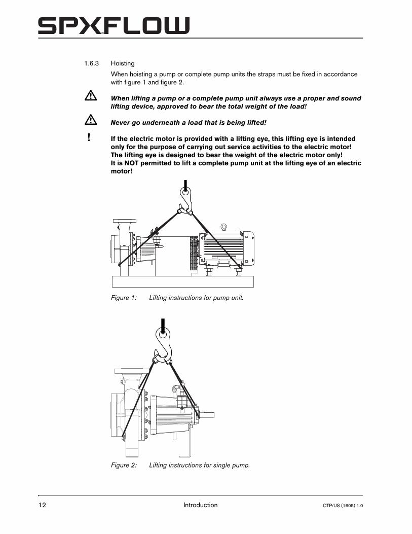
1.6.3 Hoisting
When hoisting a pump or complete pump units the straps must be fixed in accordance with figure 1 and figure 2.
� When lifting a pump or a complete pump unit always use a proper and sound lifting device, approved to bear the total weight of the load!
� Never go underneath a load that is being lifted!
! If the electric motor is provided with a lifting eye, this lifting eye is intended only for the purpose of carrying out service activities to the electric motor! The lifting eye is designed to bear the weight of the electric motor only! It is NOT permitted to lift a complete pump unit at the lifting eye of an electric motor!
Figure 1: Lifting instructions for pump unit.
Figure 2: Lifting instructions for single pump.
Introduction CTP/US (1605) 1.0
CTP/US (1605) 1.0
CombiThermPlus
1.6.4 Storage
• If the pump is not to be used immediately the pump shaft must be turned by hand twice per week.
• Pumps must be properly covered and protected against moisture, dirt, and physical damage during storage prior to installation.
1.7 Long term storage
1.7.1 Storage
If long term (>6 months) storage is anticipated, do the following:
1 Seal the suction opening of the pump with a blind flange, gasket, and bolts.
2 Fill the pump through the discharge opening with a corrosion inhibiting liquid that is also compatible with the liquid to be pumped. This compatibility regards the operating temperature as well. Remove the seal vent plug while filling to purge all air from the mechanical seal cavity. When the liquid flows through the vent connection, replace the seal vent plug. If liquid does not flow from this connection, fill through this connection until all air is purged.
3 Manually rotate the shaft several turns.
4 Continue filling through the discharge opening until the pump is completely filled.
5 Seal the discharge opening with a blind flange, gasket, and bolts.
6 For thermal oil pumps: Remove the quench fill plug. Fill the quench cavity with a corrosion inhibiting liquid that is compatible with the quench liquid that will be used later for pump operation. When this liquid starts to flow out of the overflow pipe, replace the fill plug.
7 Apply a heavy protective coating to all exposed machined surfaces. A rust preventive agent must be used to protect all steel and iron parts.
8 Rotate the pump shaft by hand each month. Wear heavy gloves when rotating the shaft, to protect your hands.
1.7.2 Putting into service after long term storage
When the pump is to be put into service after long term storage:
1 For thermal oil pumps: Remove the quench drain plug, drain and discard the storage liquid.
2 For thermal oil pumps: Remove the quench fill plug. Flush all remains of the storage liquid from the quench cavity.
3 Replace the fill and drain plugs. Use a flush liquid that is compatible with the quench fluid to be used. Be sure to comply with all local regulations in disposal of the storage liquid and the flush liquid.
4 Remove and discard the discharge bolts, nuts, blind flange, and gasket.
5 Remove the casing drain plug and the seal vent plug. Drain and discard the storage liquid.
6 Remove and discard the suction bolts, blind flange, and gasket. Stand the pump up on its suction flange to allow residual liquid to drain.
7 Flush all remains of the storage liquid from the pump. Use a flush liquid that is compatible with the pumpage, as any flush liquid remaining in the pump when it is placed in operation, will be exposed to the operating temperatures and pressures.
Introduction 13

14
Vapor pressure is one of the critical properties to be considered. Be sure to comply with all environmental regulations in disposal of the storage liquid, flush liquid and gaskets.
1.8 Ordering parts
This manual contains a survey of the spare parts recommended by SPXFLOW as well as the instructions for ordering them.
You should always state all data stamped on the type plate when ordering parts and in any other correspondence regarding the pump.
➢ This data is also printed on the label on the front of this manual.
If you have any questions or require further information with regard to specific subjects, then do not hesitate to contact SPXFLOW.
Introduction CTP/US (1605) 1.0
CTP/US (1605) 1.0
CombiThermPlus
2 General
2.1 Pump description
CombiThermPlus represents a range of centrifugal pumps, used in heat transfer systems or in hot water circulation systems.
Flange dimensions, bolt circle and number of holes comply with ASME B16.5-300lbs.
The pump is driven by a standard NEMA foot motor. The power is transmitted through a flexible coupling. Because of their modular lay-out, constructional components are widely interchangeable, also with other pump types of the Combi system.
In general, the pumps can be used for:
• thin and clean heat transfer liquids;
• system pressure for thermal oil: up to 360 psi; for hot water: up to 450 psi;
• thermal oil temperature up to 660 °F;
• hot water temperature up to 400 °F.
2.2 Applications
• Thermal oil circulation and Heat transfer.
• High temperature hot water circulation, hospitals, heating systems.
• The maximum allowed system pressure and temperature and the maximum speed depend on the pump type and the pump construction. For relevant data see paragraph 10.3 ’Maximum admissible working pressure’.
• Further details about the application possibilities of your specific pump are mentioned in the order confirmation and/or in the data sheet enclosed with the delivery.
• Do not use the pump for purposes other than those for which it is delivered without prior consultation with your supplier.
� Using a pump in a system or under system conditions (liquid, working pressure, temperature, etc.) for which it has not been designed may hazard the user!
General 15
16
2.3 Type code
Pumps are available in various designs. The main characteristics of the pump are shown in the type code.
Example: CTP 2 x 3 x 8½ NG1 M5/T
2.4 Serial number
The serial number of the pump or pump unit is shown on the name plate of the pump and on the label on the cover of this manual.
2.5 Construction
The pump has a modular design. The main components are:
• Pump casing / impeller
• Shaft sealing
• Bearing
All pumps share the same shaft design, shaft seal and bearing arrangement. Only the impeller mounting shaft end is machined in two variants, to enable mounting two types of impeller with different hub bores.
The pumps are also standardized into two groups with the same connection for the pump casing and pump cover, depending on the nominal impeller diameter. The bearing bracket is mounted to the pump cover.
2.5.1 Pump casing / impeller
This concerns the parts that are exposed to the pumped liquid. For each individual pump type there is only one design of the pump casing and the impeller. The pump casing is available in nodular cast iron, the impeller is available in cast iron or stainless steel. All pump types have a closed impeller design.
Pump family
CTP CombiThermPlus
Pump size [inch]
2 x 3 x 8½ discharge diameter x suction diameter x nominal impeller diameter
Pump casing material
NG nodular cast iron
Impeller material
1 cast iron
Shaft sealing
M5/T mechanical seal, balanced, elastomers Viton®
M5/H mechanical seal, balanced, elastomers EPDM
Example: A 111 005 01
A year of manufacture111 region number005 particular region number01 number of pumps
General CTP/US (1605) 1.0
CTP/US (1605) 1.0
CombiThermPlus
2.5.2 Shaft seal
The pump is provided with a balanced mechanical seal with mounting dimensions according to EN 12756. The mechanical seal in the Thermal Oil pump is provided with Viton® O-rings [M5/T], the Hot Water pump has EPDM O-rings [M5/H].
2.5.3 Bearing
The pumps are designed with two single-row angular contact ball bearings in O-setup and a journal bearing in the pumped liquid. The ball bearings are grease lubricated with high temperature grease. The ball bearings must be greased regularly.
2.6 Application area
The application area globally looks as follows:,
2.7 Re-use
The pump may only be used for other applications after prior consultation with SPXFLOW or your supplier. Since the lastly pumped medium is not always known, the following instructions should be observed:
1 Flush the pump properly.
2 Make sure the flushing liquid is discharged safely (environment!)
� Take adequate precautions and use the appropriate personal protection equipment like rubber gloves and spectacles!
2.8 Scrapping
If it has been decided to scrap a pump, the same flushing procedure as described for Re-use should be followed.
Table 1: Application area.
Maximum value [@60Hz]
Thermal oil Hot waterCapacity up to 1450 gpm 1450 gpmDischarge head up to 500 ft 500 ftDischarge pressure up to 360 psi 450 psiSuction pressure up to 145 psi 145 psiTemperature 660 °F 400 °FMax. ambient temperature 149 °F 149 °FMin. working temperature 12 °F 12 °F
General 17

18
General CTP/US (1605) 1.0
CTP/US (1605) 1.0
CombiThermPlus
3 Installation
3.1 Safety
• Read this manual carefully prior to installation and commissioning. Non-observance of these instructions can result in serious damage to the pump and this will not be covered under the terms of our guarantee. Follow the instructions given step by step.
• Ensure that the pump can not be started if work has to be undertaken to the pump during installation and the rotating parts are insufficiently guarded.
• Depending on the design the pumps are suitable for liquids with a temperature of up to 660°F. When installing the pump unit to work at 150 °F and above the user should ensure that appropriate protection measures and warnings are fitted to prevent contact with the hot pump parts.
• If there is danger of static electricity, the entire pump unit must be earthed.
• If the pumped liquid is harmful to men or the environment, take appropriate measures to drain the pump safely. Possible leakage liquid from the shaft seal should also be discharged safely.
3.2 Preservation
To prevent corrosion, the pump is flushed with a preserving agent before leaving the works.
• Before putting the pump into operation, drain off any preserving agent and flush the pump thoroughly with hot water, including the quench space. Be sure to comply with all environmental regulations in disposal of the preserving agent and flush water.
• A Hot Oil pump must be thoroughly dried afterwards, as any flush water remaining in the pump when it is placed in operation, will be exposed to the operating temperatures and pressures of the hot oil pumpage. Vapor pressure is one of the critical properties to be considered.
• Remove all plugs and blow-dry the inside of pump, seal chamber and quench space, using a compressed air gun. Put the pump upright, resting on the suction flange and repeat this action.
• Reinstall all plugs.
Installation 19
20
3.3 Environment
• The foundation must be hard, level and flat.
• The area in which the pump is installed must be sufficiently ventilated. An ambient temperature or air humidity which is too high, or a dusty environment, can have a detrimental effect on the operation of the electric motor.
• There should be sufficient space around the pump unit to operate and if necessary repair it.
• Behind the cooling air inlet of the motor there must be a free area of at least ¼ of the electric motor diameter, to ensure unobstructed air supply.
• When the pump casing takes on the same temperature as the fluid handled, insulate the pump casing.
! Never insulate the pump cover and bearing bracket.
3.4 Piping
• The piping to the suction and delivery connections must fit exactly and must not be subject to stress during operation. For the maximum allowable forces and moments on the pump flanges see paragraph 10.7 ’Permissible forces and moments on the flanges’.
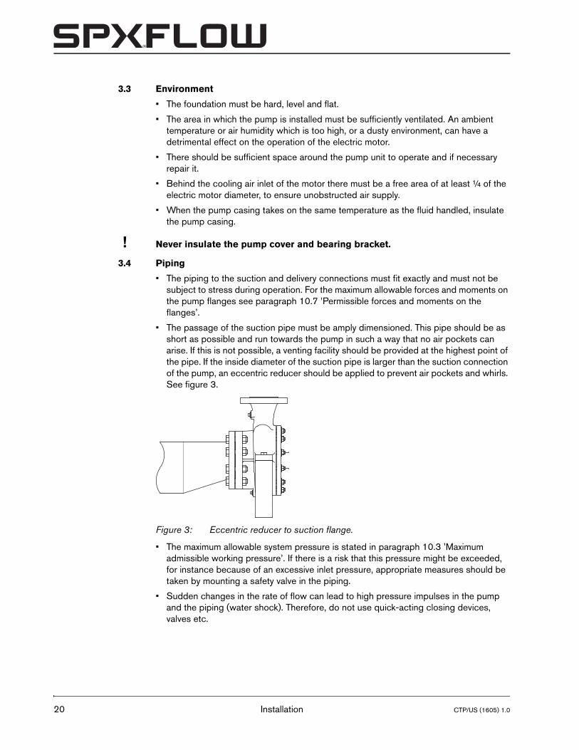
• The passage of the suction pipe must be amply dimensioned. This pipe should be as short as possible and run towards the pump in such a way that no air pockets can arise. If this is not possible, a venting facility should be provided at the highest point of the pipe. If the inside diameter of the suction pipe is larger than the suction connection of the pump, an eccentric reducer should be applied to prevent air pockets and whirls. See figure 3.
• The maximum allowable system pressure is stated in paragraph 10.3 ’Maximum admissible working pressure’. If there is a risk that this pressure might be exceeded, for instance because of an excessive inlet pressure, appropriate measures should be taken by mounting a safety valve in the piping.
• Sudden changes in the rate of flow can lead to high pressure impulses in the pump and the piping (water shock). Therefore, do not use quick-acting closing devices, valves etc.
Figure 3: Eccentric reducer to suction flange.
Installation CTP/US (1605) 1.0
CTP/US (1605) 1.0
CombiThermPlus
3.5 Accessories
• Fit any parts that may have been supplied separately.
• If the liquid does not flow towards the pump, fit a foot valve at the bottom of the suction pipe. If necessary, combine this foot valve with a suction strainer to prevent impurities from being drawn in.
• When mounting, place temporarily (for the first 24 operating hours) a fine gauze between suction flange and suction pipe to prevent internal pump parts from being damaged by foreign matter. If the risk of damage continues to exist, fit a permanent filter.
• Thermal oil pump: install the overflow line (1400) and related parts on the bearing bracket (2100). Apply Teflon tape on the thread.If applicable: Remove plug (2130) and install the optional PT-100. For connection refer to the manufacturers’ instructions.
• Hot water pump: install the de-aerator assembly (1460) and related parts on the bearing bracket (2100). Apply Teflon tape on the thread.
3.6 Installation of a pump unit
Pump and motor shafts of complete pump units are adjusted perfectly in line in the works.
1 Place the pump unit on the foundation. Align the pump flanges with the corresponding piping flanges, by shimming the baseplate, using wedges.
2 Ensure all piping to the pump is adequately bracketed. The piping may not exert any dead load on the pump flanges.
3 Connect the pump to the suction and discharge flanges. The connections must be stress-free!
• Always apply new gaskets!
• Always use fasteners of the proper size and material.
• Ensure all fasteners are properly tightened and that there are no missing fasteners!
4 Carefully tighten the nuts on the foundation bolts.
5 Check the alignment of pump and motor shafts and if necessary realign, see paragraph 3.8.3 ’Alignment’.
3.7 Assembling a pump unit
If the pump and the electric motor still have to be assembled, do the following:
1 Install the pump on the baseplate.
2 Place the electric motor on the baseplate. The distance between the pump shaft and the motor shaft must be 3.5”.
3 If size db of the pump, see paragraph 8.2.1 ’Dimensions drawing’, is not equal to the NEMA size of the motor:
• Level up the difference by placing properly sized spacers under the pump or under the motor feet.
• If the baseplate is supplied by SPXFLOW: adjust the levelling screws to obtain proper alignment of pump and motor. Secure the levelling screws with jam nuts.
4 Install the coupling. See paragraph 3.8 ’Rexnord Omega Coupling’.
Installation 21
22
3.8 Rexnord Omega Coupling
3.8.1 Elastomer element replacement
When the elastomer elements must be replaced:
• Always replace both half elements.
• Install both half elements from the same box.
3.8.2 Installation
1 Inspect both shafts and hub bores and make sure they are free from dirt and burrs.
2 Verify that the keys fit the shafts properly.
3 Mount the hub on the pump shaft. The hub must be mounted flush with the end of the pump shaft. Tighten the set screw.
4 Mount the other hub on the motor shaft. Do not tighten the set screw.
5 Mount a half elastomer element around the hub on the pump shaft, using the cap screws provided.
! Do not lubricate cap screw threads!
! Apply a drop of Loctite 641 on the cap screw threads!
! When installing the elements, first seat all cap screws with a light torque, then tighten all cap screws to proper torque using a torque wrench.
6 Use this elastomer element to determine the hub location on the motor shaft. Slide the hub on the motor shaft until the threaded holes in the hub coincide with one of the rows of holes of the hole pattern in the half element. The hub may not extend beyond the motor shaft end! There must always be a free space of 3.5” between both extremeties to permit the removal of the Back-Pull-Out unit.
7 Mount the elastomer element to the other hub, using the cap screws provided.
8 Now the hubs are properly spaced, tighten the set screw of the second hub.
9 Rotate the shaft 180 degrees and mount the second half element.
➢ If the shaft cannot be rotated, mount the half elements at 90 degrees.
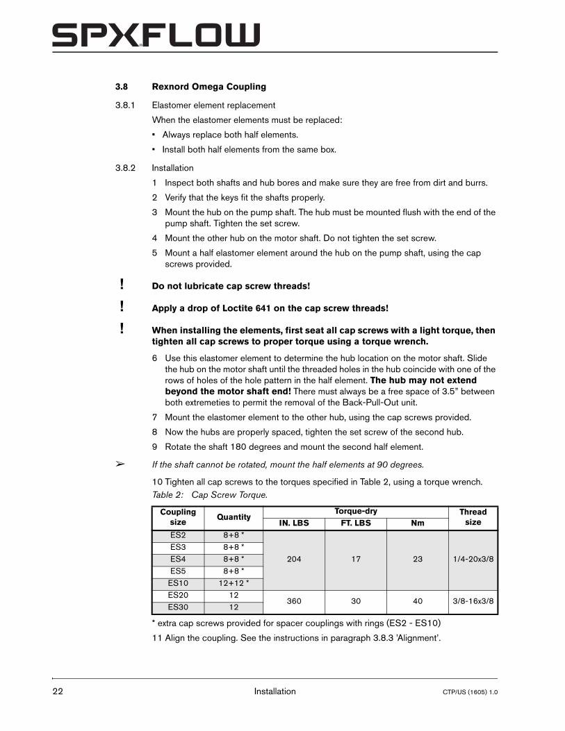
10 Tighten all cap screws to the torques specified in Table 2, using a torque wrench.
* extra cap screws provided for spacer couplings with rings (ES2 - ES10)
11 Align the coupling. See the instructions in paragraph 3.8.3 ’Alignment’.
Table 2: Cap Screw Torque.
Coupling size
QuantityTorque-dry Thread
sizeIN. LBS FT. LBS NmES2 8+8 *
204 17 23 1/4-20x3/8ES3 8+8 *ES4 8+8 *ES5 8+8 *
ES10 12+12 *ES20 12
360 30 40 3/8-16x3/8ES30 12
Installation CTP/US (1605) 1.0
CTP/US (1605) 1.0
CombiThermPlus
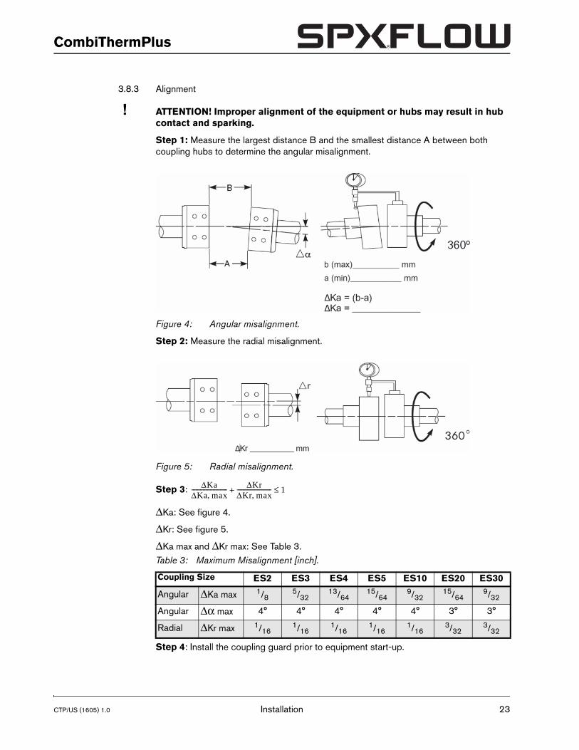
3.8.3 Alignment
! ATTENTION! Improper alignment of the equipment or hubs may result in hub contact and sparking.
Step 1: Measure the largest distance B and the smallest distance A between both coupling hubs to determine the angular misalignment.
Step 2: Measure the radial misalignment.
Step 3:
ΔKa: See figure 4.
ΔKr: See figure 5.
ΔKa max and ΔKr max: See Table 3.
Step 4: Install the coupling guard prior to equipment start-up.
Figure 4: Angular misalignment.
Figure 5: Radial misalignment.
Table 3: Maximum Misalignment [inch].
Coupling Size ES2 ES3 ES4 ES5 ES10 ES20 ES30
Angular ΔKa max 1/85/32
13/6415/64
9/3215/64
9/32
Angular Δα max 4° 4° 4° 4° 4° 3° 3°
Radial ΔKr max 1/161/16
1/161/16
1/163/32
3/32
ΔKaΔKa max,------------------------- ΔKr
ΔKr max,------------------------+ 1≤
Installation 23
24
3.9 Connection of the electric motor
� The electric motor must be connected to the mains by an approved electrician, according to the locally prevailing regulations of the electricity company.
• Refer to the instruction manual belonging to the electric motor.
• If possible, fit a working switch as close as possible to the pump.
� Only use electric motors whose cooling air flows axial direction towards the pump end.
3.10 Combustion engine
� Only use engines whose cooling air is drawn in or blown out through the coupling.
3.10.1 Safety
If the pump set is designed with a combustion engine, the manual for the engine should be included in the delivery. If the manual is missing we urgently request you to contact us immediately.
Irrespective of the manual, the following points should be observed for all combustion engines:
• Comply with the local safety regulations.
• The exhaust of combustion gases must be screened off to prevent incidental contact.
• The starting device should automatically be disengaged after the engine has been started.
• The maximum speed of the engine set by us should not be changed.
• Before starting the engine check the oil level.
3.10.2 Sense of rotation
� The sense of rotation of combustion engine and pump is indicated by means of an arrow on the combustion engine and the pump casing. Verify whether the sense of rotation of the combustion engine is the same as that of the pump.
Installation CTP/US (1605) 1.0
CTP/US (1605) 1.0
CombiThermPlus
4 Commissioning
4.1 Pump start-up checklist
Check these points after pump installation and before starting up the pump.
1 Be sure all users have read and understood the instruction manual.
2 Review the pump data sheet for the service rating of the pump and any special features.
3 Verify that the seal chamber has been vented.
4 Check all piping connections. Make sure that they are both tight and in the proper places.
5 Make sure that the base plate has been properly installed.
6 Break the coupling by removing the coupling spacer and bump the motor starting button to check motor rotation.
! Operating the pump in reverse rotation may cause extensive damage. If driver rotation is correct, replace the coupling spacer. If not, connect the wiring for proper rotation and recheck.
7 Rotate the pump shaft by hand to be sure that there is no binding or rubbing within the pump or motor. Wear heavy gloves to protect your hands. Correct any problems before proceeding.
8 Check the coupling for proper alignment. Realign if necessary.
9 Reinstall the coupling guard and verify that the coupling guard is fastened securely in place.
10 Verify that the quench fluid has been installed, if the quench fluid is required for your operation.
11 Check to be sure that the leak detection connection at the bottom of the bearing bracket is open for proper operation.
12 Remove all dirt, waste, tools, and construction debris from the area.
Commissioning 25
26
4.2 Inspection of the motor
� The cooling air flows axial direction towards the pump end should never be blocked.
Pump driven by an electric motor:
• Verify that the motor is of the fan cooled type. A fan cooled motor is necessary for successful operation of the pump.
• Check the electrical connections to the motor.
• Check whether the fuses have been mounted.
Pump driven by a combustion engine:
• Check whether the room in which the engine is placed is well ventilated.
• Check whether the exhaust of the engine is not obstructed.
• Before starting the engine check the oil level.
• Never run the engine in a closed room.
4.3 Preparing the pump unit for commissioning
Proceed as follows, both when the unit is put into operation for the first time and after the pump has been overhauled:
1 Fully open the stop valve in the suction pipe. Close the delivery stop valve.
2 Fill the pump and the suction pipe with the liquid to be pumped.
3 For thermal oil pumps: Remove plug (2130) and fill the seal chamber complete with the liquid to be pumped.
4 Turn the pump shaft a few times by hand and add more liquid, if necessary.
5 Reinstall the plug.
6 For hot water pumps: Remove plug (1480).
7 Turn the shaft a few times until pumped liquid flows out of the opening.
8 Reinstall the plug.
Commissioning CTP/US (1605) 1.0
CTP/US (1605) 1.0
CombiThermPlus
4.4 Checking the sense of rotation
� Beware of possible non-screened rotating parts, when checking the sense of rotation!
1 The sense of rotation of the pump is indicated by an arrow. Check whether the sense of rotation of the motor corresponds with that of the pump.
2 Let the motor run for only a short time and check the sense of rotation.
3 If the sense of rotation is not correct, alter the sense of rotation. See the instructions in the user manual belonging to the electric motor.
4 Fit the guard.
4.5 Start-up
1 Start the pump.
2 As soon as the pump is under pressure, slowly open the delivery stop valve until the working pressure is attained.
� Make sure that when a pump is running, rotating parts are always properly screened off by the guard!
4.6 Pump in operation
When the pump is in operation, pay attention to the following:
• The pump should never run dry.
• Never use a stop valve in the suction line to control pump output. The stop valve should always be fully opened during operation.
• Check whether the absolute inlet pressure is sufficient, to prevent vaporization in the pump.
• Check whether the pressure difference between suction and delivery side corresponds with the specifications of the pump's duty point.
! In the run-in phase of the pump, it is recommended to vent the pump several times through the plug on the bearing bracket.
4.7 Noise
The noise production of a pump depends to a great extent on the operating conditions. The values stated in paragraph 10.9 ’Noise data’ are based on normal operation of the pump, driven by an electric motor. In case the pump is driven by a combustion engine, or in case it is used outside the normal operation area, as well as in case of cavitation, the noise level may exceed 85 dB(A). In that case precautions should be taken, like building a noise-barrier around the unit or wearing hearing protection.
Commissioning 27

28
Commissioning CTP/US (1605) 1.0
CTP/US (1605) 1.0
CombiThermPlus
5 Maintenance
5.1 Daily maintenance
Regularly check the outlet pressure.
� No water should get into the terminal box of the electric motor when the pump room is sprayed clean! Never spray water on hot pump parts! The sudden cooling down may cause them to burst and hot water may flow out!
! Flawed maintenance will result in shorter lifespan, possible break down and in any event loss of warranty.
5.2 Mechanical seal
A mechanical seal generally requires no maintenance, however, it should never be allowed to run dry. If there are no problems, do not dismantle the mechanical seal. As the seal faces have run in on one another dismantling usually implicates replacement of the mechanical seal. If a mechanical seal shows any leakage it has to be replaced.
5.3 Lubrication of the bearings
• The drive-end bearing (2240) are grease lubricated with high temperature grease and must be lubricated regularly every 2000 hours with a shot of fresh grease with a grease gun. See paragraph 10.2 ’Lubricants and sealants’ for the grease specifications.
• The pump-end bearing bush (2230) is lubricated by the fluid handled.
• The bearings do not require any maintenance.
• It is recommended to replace the bearings after 5 years of operation or 40.000 operating hours.
Maintenance 29
30
5.4 Environmental influences
• Regularly clean the filter in the suction pipe or the suction strainer at the bottom of the suction pipe, as the inlet pressure may become too low if the filter or the suction strainer is fouled.
• If there is a risk that the pumped liquid expands during solidification or freezing, the pump has to be drained and, if necessary, flushed after it has been put out of service.
• If the pump is out of service for a long time, it has to be preserved.
• Check motor for accumulation of dust or dirt, which might influence motor temperature.
5.5 Noise
If a pump starts making noise, this may point to certain problems with the pump unit. A crackling noise can indicate cavitation or excessive motor noise can indicate deterioration of the bearings.
5.6 Motor
Check motor specifications for start-stop frequency.
5.7 Faults
� The pump, of which you want to determine the fault, may be hot or under pressure. Take the appropriate precautions first and protect yourself with the proper safety devices (safety goggles, gloves, protective clothing)!
To determine the source of the malfunctioning of the pump, proceed as follows:
1 Switch off the power supply to the pump unit. Lock the working switch with a padlock or remove the fuse. In case of a combustion engine: switch off the engine and close the fuel supply to the engine.
2 Close the stop valves.
3 Determine the nature of the fault.
4 Try to determine the cause of the fault with chapter 6 "Problem solving" and take the appropriate measures or contact your installer.
Maintenance CTP/US (1605) 1.0
CTP/US (1605) 1.0
CombiThermPlus
6 Problem solving
Faults in a pump installation can have various causes. The fault may not be in the pump, it may also be caused by the pipe system or the operating conditions. Firstly, always check that installation has been executed in accordance with the instructions in this manual and that the operating conditions still correspond with the specifications for which the pump was purchased.
In general, breakdowns in a pump installation are attributable to the following causes:
• Faults with the pump.
• Breakdowns or faults in the pipe system.
• Faults due to incorrect installation or commissioning.
• Faults due to incorrect choice of pump.
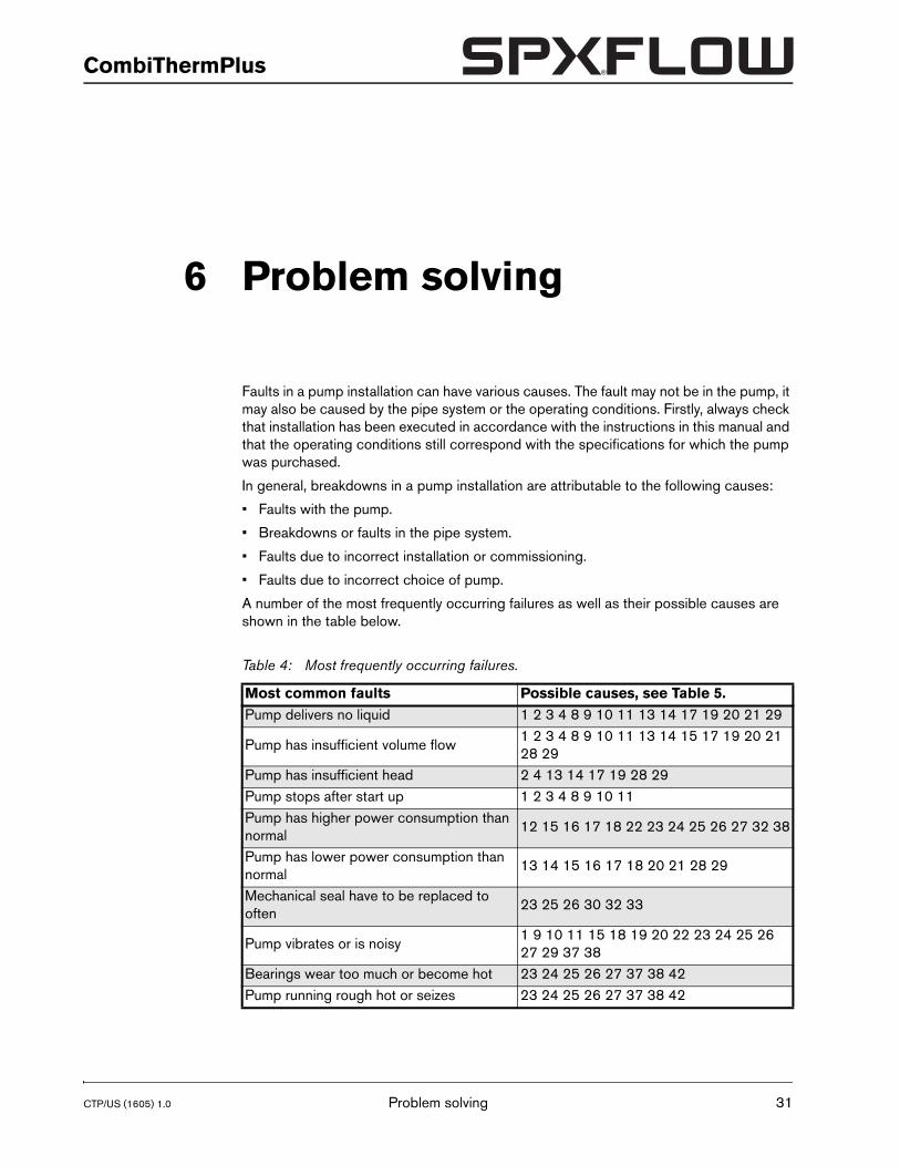
A number of the most frequently occurring failures as well as their possible causes are shown in the table below.
Table 4: Most frequently occurring failures.
Most common faults Possible causes, see Table 5.Pump delivers no liquid 1 2 3 4 8 9 10 11 13 14 17 19 20 21 29
Pump has insufficient volume flow1 2 3 4 8 9 10 11 13 14 15 17 19 20 21 28 29
Pump has insufficient head 2 4 13 14 17 19 28 29Pump stops after start up 1 2 3 4 8 9 10 11Pump has higher power consumption than normal
12 15 16 17 18 22 23 24 25 26 27 32 38
Pump has lower power consumption than normal
13 14 15 16 17 18 20 21 28 29
Mechanical seal have to be replaced to often
23 25 26 30 32 33
Pump vibrates or is noisy1 9 10 11 15 18 19 20 22 23 24 25 26 27 29 37 38
Bearings wear too much or become hot 23 24 25 26 27 37 38 42Pump running rough hot or seizes 23 24 25 26 27 37 38 42
Problem solving 31
32
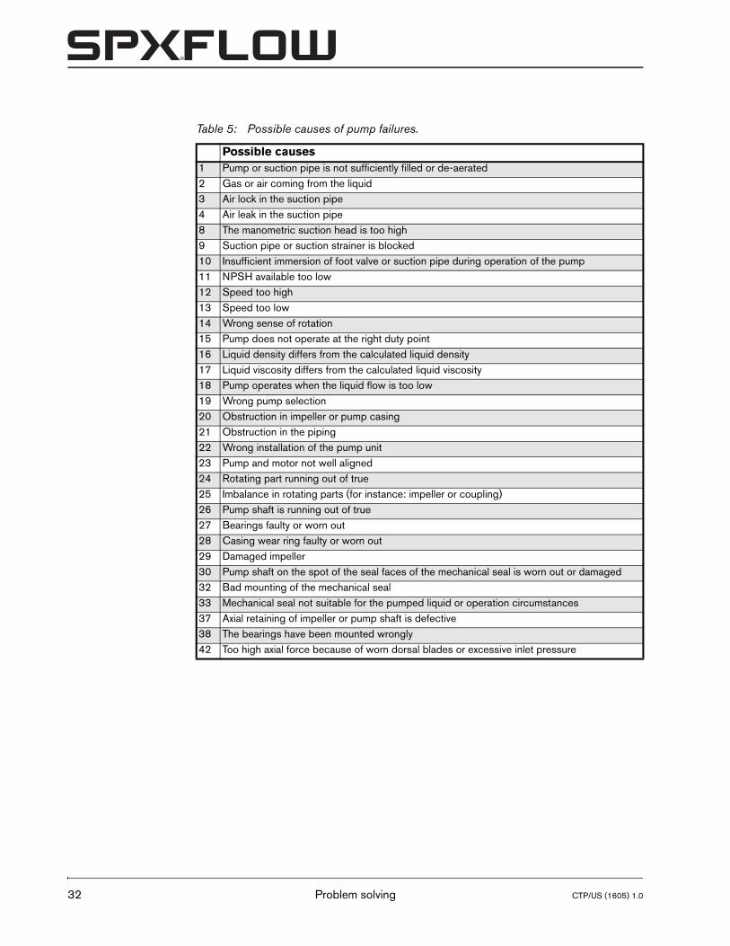
Table 5: Possible causes of pump failures.
Possible causes1 Pump or suction pipe is not sufficiently filled or de-aerated2 Gas or air coming from the liquid3 Air lock in the suction pipe4 Air leak in the suction pipe8 The manometric suction head is too high9 Suction pipe or suction strainer is blocked10 Insufficient immersion of foot valve or suction pipe during operation of the pump11 NPSH available too low12 Speed too high13 Speed too low14 Wrong sense of rotation15 Pump does not operate at the right duty point16 Liquid density differs from the calculated liquid density17 Liquid viscosity differs from the calculated liquid viscosity18 Pump operates when the liquid flow is too low19 Wrong pump selection20 Obstruction in impeller or pump casing21 Obstruction in the piping22 Wrong installation of the pump unit23 Pump and motor not well aligned24 Rotating part running out of true25 Imbalance in rotating parts (for instance: impeller or coupling)26 Pump shaft is running out of true27 Bearings faulty or worn out28 Casing wear ring faulty or worn out29 Damaged impeller30 Pump shaft on the spot of the seal faces of the mechanical seal is worn out or damaged32 Bad mounting of the mechanical seal33 Mechanical seal not suitable for the pumped liquid or operation circumstances37 Axial retaining of impeller or pump shaft is defective38 The bearings have been mounted wrongly42 Too high axial force because of worn dorsal blades or excessive inlet pressure
Problem solving CTP/US (1605) 1.0
CTP/US (1605) 1.0
CombiThermPlus
7 Disassembly and assembly
7.1 Precautionary measures
� Take adequate measures to avoid that the motor is started while you are working on the pump. This is especially important for electric motors with remote control:
• Switch the operating switch near the pump (if available) to "OFF".
• Switch off the pump switch on the switchboard.
• If necessary remove the fuses.
• Hang a danger board near the switchboard cabinet.
� The pump must have cooled down to ambient temperature.
7.2 Draining
! Make sure no liquid or oil gets into the environment!
Before starting any disassembly the pump should be drained.
1 If necessary, close the valves in the suction and delivery pipe.
2 Remove the drain plugs (0310) and (2150).
3 Place a container under the drain port of the bearing bracket.
4 Remove the drain plug (2145) to evacuate the quench oil (Thermal oil pump only). Reinstall the plug after draining the oil.
5 If harmful liquids are pumped wear protective gloves, shoes, glasses, etc., and thoroughly flush the pump.
6 Refit the drain plugs.
� If possible, wear protective gloves. Regular contact with oil products may result in allergic reactions.
Disassembly and assembly 33
34
7.3 Tools
The following tools are needed for disassembling and assembling the pump.
• Hydraulic press
• Work bench. The work bench must be provided with a hole or aperture to contain the shaft end during assembly.
• Circlip pliers
• Vice with copper covered jaws
• Thermostat controlled electric hot plate for pre-heating bearings
• Oven for temperature up to 660 °F for carbon journal bearing bush
• Hook spanner for lock nut
• Plastic mallet
• Hammer
• Torque wrench
• Sockets for pump cover nuts and pump casing nuts
• Allen screw bits
• Metric sockets M12 and M16 for impeller cap nut
• Lifting device, crane to lift and lower the heavier assembled parts.
➢ Cover the work bench with sheets of cardboard to avoid damage to the machined parts.
➢ Ensure the work bench is clean.
Disassembly and assembly CTP/US (1605) 1.0
CTP/US (1605) 1.0
CombiThermPlus
7.4 Back-Pull-Out system
The pumps are designed with a Back-Pull-Out system. If the pump unit is designed with a spacer-coupling, just remove the spacer. After that the bearing bracket with the entire rotating part can be removed. This means that almost the whole pump can be dismantled without having to detach the suction and delivery piping. The motor remains in its position.
If the pump unit does not have a spacer coupling, the motor has to be removed from the foundation before disassembly.
7.4.1 Disassembling the coupling guard
1 Loosen the fixation screws (0230) and remove these these including washers (0232).
2 Remove the coupling guard (0270) from the coupling.
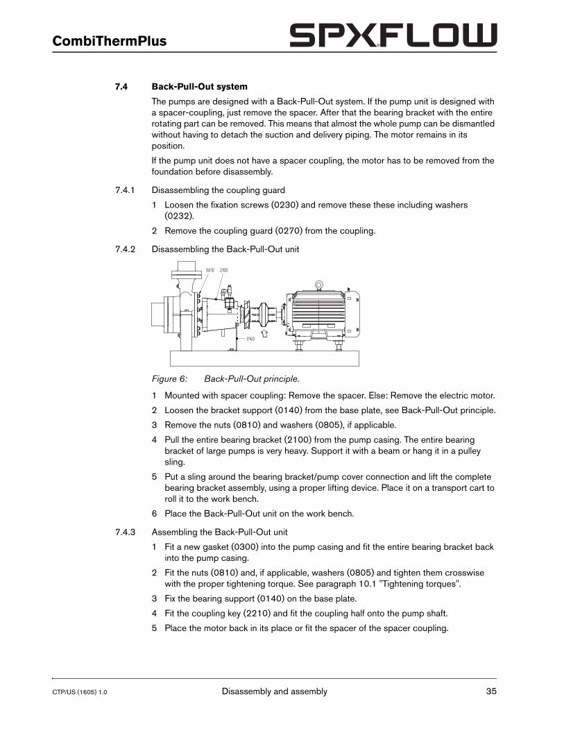
7.4.2 Disassembling the Back-Pull-Out unit
1 Mounted with spacer coupling: Remove the spacer. Else: Remove the electric motor.
2 Loosen the bracket support (0140) from the base plate, see Back-Pull-Out principle.
3 Remove the nuts (0810) and washers (0805), if applicable.
4 Pull the entire bearing bracket (2100) from the pump casing. The entire bearing bracket of large pumps is very heavy. Support it with a beam or hang it in a pulley sling.
5 Put a sling around the bearing bracket/pump cover connection and lift the complete bearing bracket assembly, using a proper lifting device. Place it on a transport cart to roll it to the work bench.
6 Place the Back-Pull-Out unit on the work bench.
7.4.3 Assembling the Back-Pull-Out unit
1 Fit a new gasket (0300) into the pump casing and fit the entire bearing bracket back into the pump casing.
2 Fit the nuts (0810) and, if applicable, washers (0805) and tighten them crosswise with the proper tightening torque. See paragraph 10.1 "Tightening torques".
3 Fix the bearing support (0140) on the base plate.
4 Fit the coupling key (2210) and fit the coupling half onto the pump shaft.
5 Place the motor back in its place or fit the spacer of the spacer coupling.
Figure 6: Back-Pull-Out principle.
0810 2100
0140
Disassembly and assembly 35
36
6 Check the alignment of pump and motor shaft, see paragraph 3.4.3 "Alignment of the coupling". If necessary, realign.
7.4.4 Assembling the coupling guard
1 Place the coupling guard (0270) over the coupling.
2 Fix it to the baseplate with fixation screws (0230). Place washers (0232) under the screw heads.
7.5 Disassembling the pump
1 Remove the Back-Pull-Out unit, see paragraph 7.4.2 "Disassembling the Back-Pull-Out unit".
2 Block the impeller (0120) with a rod and unscrew the impeller cap nut (1820). IMPORTANT: Apply a METRIC socket M12 or M16!
3 Remove the cap nut.
4 Remove the impeller (0120) with a pulley puller, or wrest the impeller by inserting for instance 2 big screwdrivers between the impeller and the pump cover (0110).
5 Remove the impeller key (1860).
7.6 Removing the pump cover
1 Remove circlip (1850).
2 Unscrew nuts (0860) and remove nuts and washers (0870).
3 Remove the pump cover (0110).
4 Remove gasket (0330) and carefully clean the mating faces of the pump cover (0110) and the bearing bracket (2100).
7.7 Removing the fan
1 Place the assembly upright on work bench, with the shaft end clamped in the vice.
2 Remove the coupling half from the pump shaft (2200), using a properly fitting pulley puller.
3 Remove the coupling key (2210). Be careful not to damage the machined shaft surface.
4 Unscrew the Allen screws (1260), remove spring washers (1265) and remove the fan (1250) from the pump shaft (2200).
5 Loosen the Allen screw and remove the shaft collar (1255) from the pump shaft. In case it is stuck on the shaft remove the Allen screw and wrest the shaft collar by inserting 2 big screwdrivers between the shaft collar and the bearing cover (2110).
7.8 Removing the bearing assembly
1 Unscrew Allen screws (2810) and remove the bearing cover (2110). Inspect the oil catcher (2180). Replace when damaged or worn out.
2 Tap the shaft at impeller side, using a plastic mallet and remove the shaft with bearings and seal housing from the bearing bracket (2100).
3 Bend back the bent tab of the lock washer (2570), to release it from the slot of the lock nut, using a drift and a hammer.
4 Unscrew the lock nut (2560). Remove lock nut and lock washer. Discard of the lock washer.
Disassembly and assembly CTP/US (1605) 1.0
CTP/US (1605) 1.0
CombiThermPlus
5 Place the shaft assembly under the hydraulic press, with the shaft drive end up. Support the outer edge of the shaft seal housing (1230). Do not rest the shaft seal housing on the protruding collar of the stationary ring of the mechanical seal (1230)!
6 Press down the shaft until the bearings and the seal housing are free.
7 Remove the bearings (2240), NILOS ring (2320), adjustment ring (2340) and the inner ring (2350).
8 Remove O-ring (2160) and O-ring (2850) from the seal housing. If the O-ring (2160) is not present on the seal housing, it means the O-ring is still in its groove inside the bearing bracket (2100). If this is the case, remove the O-ring from its groove.
9 Remove the rotating part of the mechanical seal (1230) from the pump shaft.
10 Remove the stationary part of the mechanical seal (1230) from the seal housing.
Disassembly and assembly 37
38
7.9 Replacing the impeller and the wear ring
The gap between the impeller and the wear ring is 0,011” to the diameter on supply. In case the gap has increased to 0,019”-0,027” due to wear, the impeller and the wear ring should be replaced.
7.9.1 Disassembling the impeller
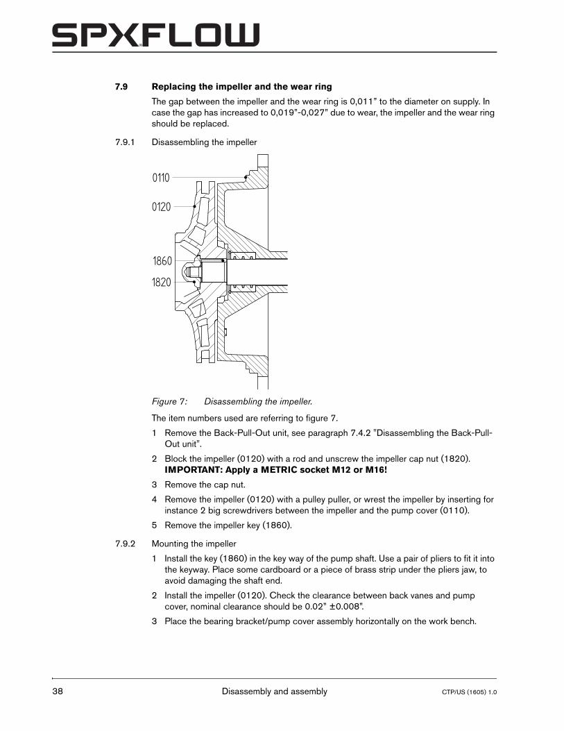
The item numbers used are referring to figure 7.
1 Remove the Back-Pull-Out unit, see paragraph 7.4.2 "Disassembling the Back-Pull-Out unit".
2 Block the impeller (0120) with a rod and unscrew the impeller cap nut (1820). IMPORTANT: Apply a METRIC socket M12 or M16!
3 Remove the cap nut.
4 Remove the impeller (0120) with a pulley puller, or wrest the impeller by inserting for instance 2 big screwdrivers between the impeller and the pump cover (0110).
5 Remove the impeller key (1860).
7.9.2 Mounting the impeller
1 Install the key (1860) in the key way of the pump shaft. Use a pair of pliers to fit it into the keyway. Place some cardboard or a piece of brass strip under the pliers jaw, to avoid damaging the shaft end.
2 Install the impeller (0120). Check the clearance between back vanes and pump cover, nominal clearance should be 0.02” ±0.008”.
3 Place the bearing bracket/pump cover assembly horizontally on the work bench.
Figure 7: Disassembling the impeller.
0110
0120
1820
1860
Disassembly and assembly CTP/US (1605) 1.0

CTP/US (1605) 1.0
CombiThermPlus
4 Apply a drop of LOCTITE 641 to the thread of the cap nut (1820) and install the cap nut.
5 Block the impeller with a rod.
6 Tighten the cap nut with a torque wrench, applying the tightening torque as stated in paragraph 10.1 "Tightening torques". IMPORTANT: Apply a METRIC socket M12 or M16!
Disassembly and assembly 39
40
7.9.3 Disassembling the wear ring
After removing the Back-Pull-Out unit the wear ring can be removed. In most cases the ring has been fixed so tightly that it cannot be removed undamaged.
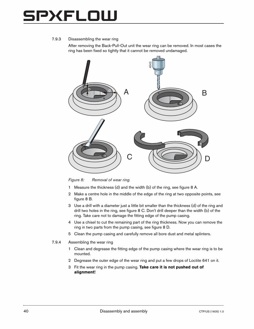
1 Measure the thickness (d) and the width (b) of the ring, see figure 8 A.
2 Make a centre hole in the middle of the edge of the ring at two opposite points, see figure 8 B.
3 Use a drill with a diameter just a little bit smaller than the thickness (d) of the ring and drill two holes in the ring, see figure 8 C. Don't drill deeper than the width (b) of the ring. Take care not to damage the fitting edge of the pump casing.
4 Use a chisel to cut the remaining part of the ring thickness. Now you can remove the ring in two parts from the pump casing, see figure 8 D.
5 Clean the pump casing and carefully remove all bore dust and metal splinters.
7.9.4 Assembling the wear ring
1 Clean and degrease the fitting edge of the pump casing where the wear ring is to be mounted.
2 Degrease the outer edge of the wear ring and put a few drops of Loctite 641 on it.
3 Fit the wear ring in the pump casing. Take care it is not pushed out of alignment!
Figure 8: Removal of wear ring.
A B
C D40
43
b d
Disassembly and assembly CTP/US (1605) 1.0
CTP/US (1605) 1.0
CombiThermPlus
7.10 Assembly instructions
7.10.1 Lubricants and sealants
The following lubricants and sealants are required for assembly
• SKF bearing grease LGHP 2/1 or equivalent
• Loctite 641
• Silicon grease
• Molycote grease
• Teflon tape
7.10.2 Instructions for mounting a mechanical seal
➢ First read the following instructions regarding the mounting of a mechanical seal. Follow these instructions closely when mounting a mechanical seal.
• A mechanical seal is a fragile precision instrument. Leave the seal in its original packing until you are ready to fit it!
• Clean all receiving parts properly. Make sure your hands and working environment are clean!
• Never touch the sliding surfaces with ones fingers!
• Take care not to damage the seal during assembly. Never put the rings down on their sliding surfaces!
7.10.3 Instructions for assembly of bearings
➢ First read the following instructions regarding assembly. Follow these instructions closely when assembling bearings.
• Make sure your working place is clean.
• Leave the bearings in their original packing as long as possible.
• Make sure the pump shaft and the bearing seats do have a smooth surface, free of burrs.
• Slightly oil the pump shaft and the other relevant parts before assembly.
• Preheat the bearings to 230 °F before mounting them on the pump shaft.
7.11 Assembly
All item numbers refer to drawings and parts lists in chapter 9 "Parts".
7.11.1 Installing the mechanical seal
1 Pre-heat the inner ring (2350) on the hotplate. Set the temperature to 230 °F.
2 Clamp the pump shaft (2200) upright in the vice, drive end upward.
3 Install the inner ring (2350) when it has the set temperature. Push it against the shaft shoulder. Let it cool down.
4 Place the seal housing (1230) flat on the work bench, with the rear end up.
5 Install oil seal or oil catcher (2185). Carefully tap it in its seat, using a plastic hammer.
6 Turn over the seal housing (1230) and place it flat on the work bench, with the seal seat up.
Disassembly and assembly 41
42
7 Lube the O-ring of the stationary ring of the mechanical seal (1220) with some silicon grease and install the O-ring on the seal ring.
8 Install the stationary ring in the seal housing (1230). Ensure the lock pin (1270) in the seal housing slots into the slot in the seal ring. Press the stationary seal ring straight in, using a properly fitting plastic pressure piece. Clean the sliding face of the seal ring, using a soft non-abrasive cloth.
9 Clamp the pump shaft in the vice, with the drive end up.
10 Slide the drive collar of the rotary part of the mechanical seal (1220) with the spring side upward on the pump shaft (2200) until it rests on the shaft shoulder.
11 Lube the O-ring of the rotary ring of the mechanical seal (1220) with some silicon grease and install the O-ring in the seal ring.
12 Install the rotary seal ring in the drive collar on the pump shaft. Ensure the slots in the seal ring corresponds with the anti-rotation tabs of the drive collar. Clean the sliding face of the seal ring, using a soft non-abrasive cloth.
13 Lube the oil seal (2185) with some silicon grease and carefully install the seal housing (1230) on the pump shaft (2200), with the seal ring down and the oil seal up. Be careful not to damage the mechanical seal.
14 Install the adjusting ring (2340) on the pump shaft.
15 Install the NILOS ring (2320) on the pump shaft, with the convex side up.
7.11.2 Installing the bearings
1 Pre-heat a ball bearing (2240) on the hotplate. Set the temperature to 230 °F.
2 Install the ball bearing when it has the set temperature. IMPORTANT: The thicker part of the bearing inner ring must FACE THE ADJUSTING RING (2340) and NILOS ring (2320). Push it firmly against the shaft shoulder. Let it cool down.
3 Fill the space between the bearing balls with SKF bearing grease LGHP 2/1.
4 Pre-heat the other ball bearing (2240) on the hotplate. Set the temperature to 230 °F.
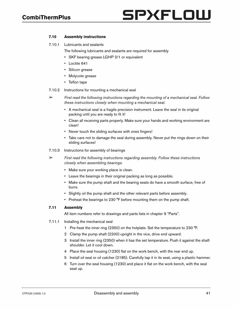
5 Install the ball bearing when it has the set temperature. IMPORTANT: the thicker part of the bearing inner ring must point to the rear end of the shaft. Push it firmly against the shaft shoulder. Let it cool down. Be sure that the ball bearings (2240) and inner ring (2350) are firmly positioned against the shaft shoulder. Verify the length of the compressed mechanical seal l3= 1.516” [38.5 mm]. See figure 9.
6 Install a new lock washer (2570).
Figure 9: Length L3 of compressed seal.
l3
Disassembly and assembly CTP/US (1605) 1.0
CTP/US (1605) 1.0
CombiThermPlus
! Never reuse used lock washers!
7 Install the lock nut (2560) and tighten the nut, using a proper fitting hook spanner and a hammer. Bend a tab of the lock washer in the slot of the lock nut, using a drift and a hammer.
8 Fill the space between the bearing balls with SKF bearing grease LGHP 2/1.
7.11.3 Installing the journal bearing
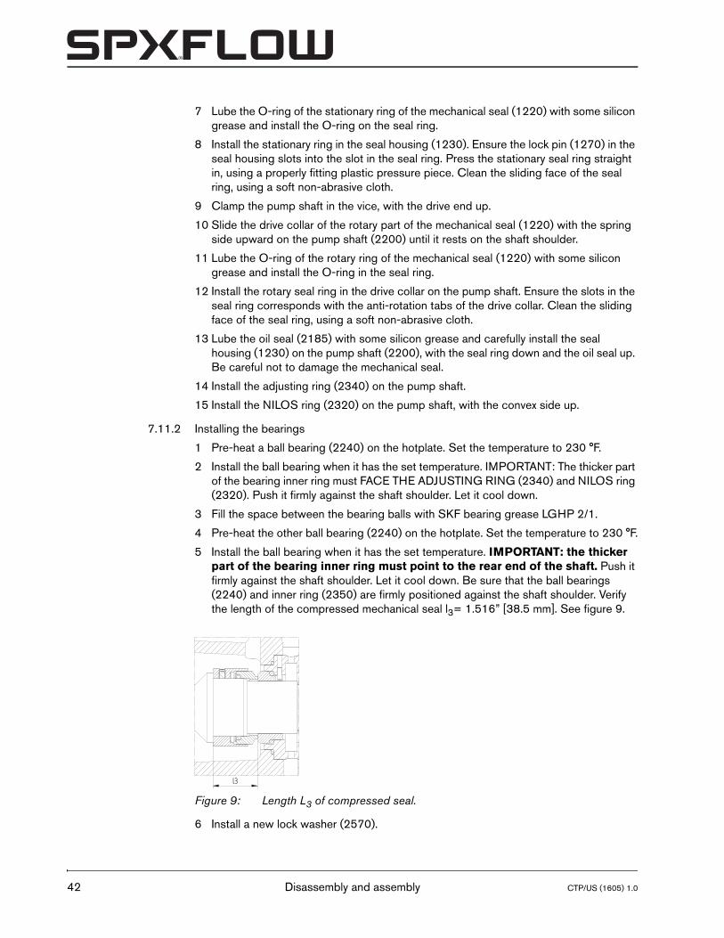
1 The bearing holder (2840) is provided with 4 holes. Mark the position of a non-threaded hole (e.g. with a felt tip pen or a sticker).
2 Also mark the top of the bearing bracket (2100).
3 Install the bearing holder (2840) in the bearing bracket, the marked non-threaded hole facing towards the marked top of the bearing bracket.
4 Place the bearing bracket under the hydraulic press and press in the bearing holder, using a properly dimensioned bush. Press until the collar of the bearing holder abuts the holder seat. The bearing holder must be recessed in the bearing bracket for at least 0.039”.
7.11.4 Assembling the pump cover
1 Place the pump cover (0110) flat on the work bench, resting on the connection flange.
2 Install the throttling bush (1210) and press it in the pump cover, using the hydraulic press.
3 Install the inner circlip (1850), using a properly fitting pair of circlip pliers.
7.11.5 Bearing bracket
1 Apply some LOCTITE 641 to the outer rim of the oil catcher (2180) and hammer it in the bearing cover (2110), using a plastic hammer, until it is flush with the bearing cover.
2 Put the bearing bracket (2100) upright on the work bench, with the rear end up, the shaft protruding the hole in the work bench.
3 Lube the O-ring (2160) with some silicon grease and install in the groove inside the bearing bracket.
4 Lube the O-ring (2850) with some silicon grease and install it in the groove of the seal housing assembly (1230) on the pump shaft.
Figure 10: A = non-threaded hole, B = threaded hole.
A
A
BB
Disassembly and assembly 43
44
5 Install the complete pump shaft assembly in the bearing bracket (2100). Carefully tap it in, using a plastic hammer, until the rear bearing is flush with the bearing bracket.
6 Install the bearing cover (2110). Fix it with Allen screws (2810). Ensure the hole for grease nipple lines up with the top of the bearing bracket.
7 Turn over the complete bearing bracket assembly and place it on the work bench, resting on the bearing cover, the shaft protruding the hole in the work bench.
8 Install the studs (0860) in the bearing bracket.
9 Install a new gasket (0330) in the bearing bracket.
10 Install the pump cover (0110). Fix it with nuts (0870). Tighten the nuts crosswise, using a torque wrench, applying the tightening torque from the table paragraph 10.1 "Tightening torques".
7.11.6 Impeller
1 Install the key (1860) in the key way of the pump shaft. Use a pair of pliers to fit it into the keyway. Place some cardboard or a piece of brass strip under the pliers jaw, to avoid damaging the shaft end.
2 Install the impeller (0120). Check the clearance between back vanes and pump cover, nominal clearance should be 0.02” ±0.008”.
3 Place the bearing bracket/pump cover assembly horizontally on the work bench.
4 Apply a drop of LOCTITE 641 to the thread of the cap nut (1820) and install the cap nut.
5 Block the impeller with a rod.
6 Tighten the cap nut with a torque wrench, applying the tightening torque as stated in paragraph 10.1 "Tightening torques". IMPORTANT: apply a METRIC socket M12 or M16!
7.11.7 Assembling the pump
1 Install the gasket (0300) in the pump casing.
2 Put a sling around the bearing bracket/pump cover connection and lift the complete bearing bracket assembly, using a proper lifting device.
3 Lower the assembly onto the pump casing. Ensure the studs protrude the holes of the pump casing flange.
4 Lube the studs with some Molycote grease and install the nuts (0810) with washers (0805), if applicable. Tighten the nuts crosswise, with a torque wrench, applying the tightening torque as stated in paragraph 10.1 "Tightening torques".
5 Put some Teflon tape on the plugs (2145 and 2150) and install them in the bearing bracket (2100).
6 Install the centerline support (0410). Fix it with bolts (0880).
7 Install the bracket support (0140). Fix it with Allen screw (2820) and washer (2830).
8 Lift the pump and place it horizontally on the work bench, resting on the centerline support and the bracket support.
9 Apply some Teflon tape on the thread and install the constant level oiler (2140) and the quench lines.
Disassembly and assembly CTP/US (1605) 1.0
CTP/US (1605) 1.0
CombiThermPlus
10 Install the shaft collar (1255) on the pump shaft, push it against the shaft shoulder and tighten the Allen screw, using a torque wrench, applying the tightening torque from the table paragraph 10.1 "Tightening torques".
11 Install the fan (1250) with the Allen screws (1260) and spring washers (1265) to the shaft collar (1255). See paragraph 10.1 "Tightening torques".
Disassembly and assembly 45

46
Disassembly and assembly CTP/US (1605) 1.0
CTP/US (1605) 1.0
CombiThermPlus
8 Dimensions
Dimensions 47
48
aaae
acag
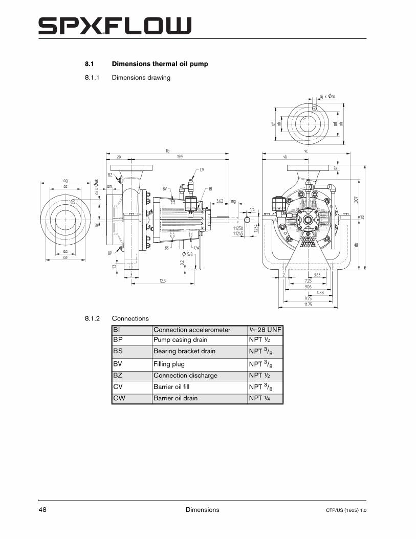
8.1 Dimensions thermal oil pump
8.1.1 Dimensions drawing
8.1.2 Connections
BI Connection accelerometer ¼-28 UNFBP Pump casing drain NPT ½
BS Bearing bracket drain NPT 3/8
BV Filling plug NPT 3/8BZ Connection discharge NPT ½
CV Barrier oil fill NPT 3/8CW Barrier oil drain NPT ¼
4.88
3.637.259.06
11.75
dbzd
an
ai x
Oak
abaf ad ah
aj x Oal
0.2
1.3
12.53
am
zb 19.5tb
3.62
vcvb
O 5/8
av
BZ
BP
BV
BS CW
1.12451.1250
1/4
1.234
mg
9.75
207
2
BI
CV
Dimensions CTP/US (1605) 1.0
CTP/US (1605) 1.0
CombiThermPlus
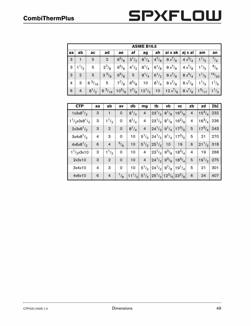
ASME B16.5
aa ab ac ad ae af ag ah ai x ak aj x al am an
3 1 5 2 65/8 31/2 81/4 47/8 8 x7/8 4 x3/4 11/57/9
3 11/2 5 27/8 65/8 41/2 81/4 61/8 8 x7/8 4 x7/8 11/58/9
3 2 5 3 5/8 65/8 5 81/4 61/2 8 x7/8 8 x3/4 11/519/20
4 3 6 3/16 5 77/8 65/8 10 81/4 8 x7/8 8 x7/8 11/3 11/5
6 4 81/2 6 3/16 105/8 77/8 121/2 10 12 x7/8 8 x7/8 19/17 11/3
CTP aa ab av db mg tb vb vc zb zd [lb]
1x3x81/2 3 1 0 81/4 4 231/2 81/8 162/8 4 153/4 232
11/2x3x81/2 3 11/2 0 81/4 4 231/2 81/8 162/8 4 163/4 236
2x3x81/2 3 2 0 81/4 4 241/2 91/4 173/5 5 173/4 243
3x4x81/2 4 3 0 10 51/2 241/2 91/4 173/5 5 21 270
4x6x81/2 6 4 5/8 10 51/2 251/2 10 19 6 211/2 318
11/2x3x10 3 11/2 0 10 4 231/2 93/8 183/4 4 19 268
2x3x10 3 2 0 10 4 241/2 93/8 183/4 5 191/2 275
3x4x10 4 3 0 10 51/2 241/2 97/8 191/4 5 21 301
4x6x10 6 4 1/8 111/2 51/2 251/2 122/5 232/8 6 24 407
Dimensions 49
50
aaae
acag
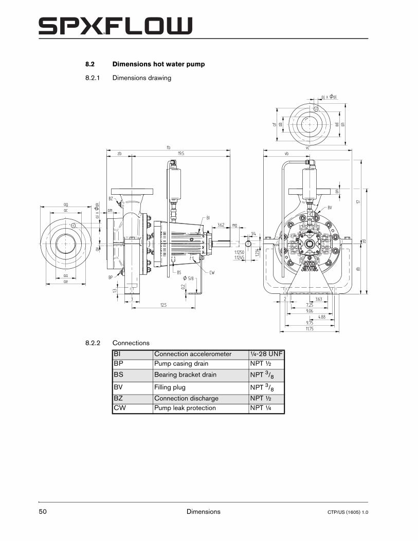
8.2 Dimensions hot water pump
8.2.1 Dimensions drawing
8.2.2 Connections
BI Connection accelerometer ¼-28 UNFBP Pump casing drain NPT ½
BS Bearing bracket drain NPT 3/8
BV Filling plug NPT 3/8BZ Connection discharge NPT ½CW Pump leak protection NPT ¼
4.88
3.637.259.06
11.75
dbzd
an
ai x
Oak
abaf ad ah
aj x Oal
0.2
1.3
12.53
am
zb 19.5tb
3.62
vcvb
O 5/8
av
BZ
BPBS
BV
1.12451.1250
1/4
1.234
mg
9.75
17
2
CW
BI
Dimensions CTP/US (1605) 1.0

CTP/US (1605) 1.0
CombiThermPlus
ASME B16.5aa ab ac ad ae af ag ah ai x ak aj x al am an
3 1 5 2 65/8 31/2 81/4 47/8 8 x7/8 4 x3/4 11/57/9
3 11/2 5 27/8 65/8 41/2 81/4 61/8 8 x7/8 4 x7/8 11/58/9
3 2 5 3 5/8 65/8 5 81/4 61/2 8 x7/8 8 x3/4 11/519/20
4 3 63/16 5 77/8 65/8 10 81/4 8 x7/8 8 x7/8 11/3 11/5
6 4 81/2 6 3/16 105/8 77/8 121/2 10 12 x7/8 8 x7/8 19/17 11/3
CTP aa ab av db mg tb vb vc zb zd [lb]
1x3x81/2 3 1 0 81/4 4 231/2 81/8 162/8 4 153/4 232
11/2x3x81/2 3 11/2 0 81/4 4 231/2 81/8 162/8 4 163/4 236
2x3x81/2 3 2 0 81/4 4 241/2 91/4 173/5 5 173/4 244
3x4x81/2 4 3 0 10 51/2 241/2 91/4 173/5 5 21 271
4x6x81/2 6 4 5/8 10 51/2 251/2 10 19 6 211/2 319
11/2x3x10 3 11/2 0 10 4 231/2 93/8 183/4 4 19 268
2x3x10 3 2 0 10 4 241/2 93/8 183/4 5 191/2 276
3x4x10 4 3 0 10 51/2 241/2 97/8 191/4 5 21 302
4x6x10 6 4 1/8 111/2 51/2 251/2 122/5 232/8 6 24 408
Dimensions 51
52
4.5
zb
a
aa
1.25
Ofa
BZ
BP
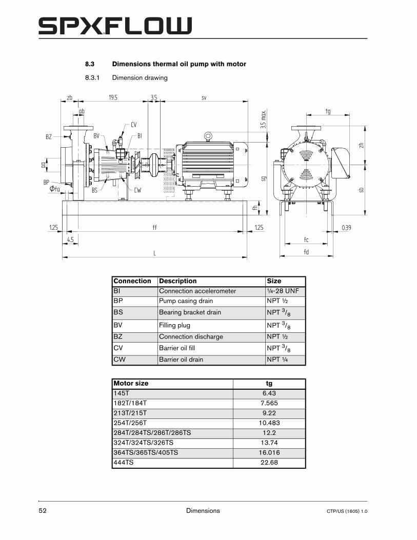
8.3 Dimensions thermal oil pump with motor
8.3.1 Dimension drawing
Connection Description SizeBI Connection accelerometer ¼-28 UNFBP Pump casing drain NPT ½
BS Bearing bracket drain NPT 3/8
BV Filling plug NPT 3/8BZ Connection discharge NPT ½
CV Barrier oil fill NPT 3/8CW Barrier oil drain NPT ¼
Motor size tg145T 6.43182T/184T 7.565213T/215T 9.22254T/256T 10.483284T/284TS/286T/286TS 12.2324T/324TS/326TS 13.74364TS/365TS/405TS 16.016444TS 22.68
fhfd
19.5 3.5 sv
tg
0.39
sbzh
b
L
fc
ff 1.25
sg3.5
max
.
BV
BS CW
BI
CV
Dimensions CTP/US (1605) 1.0
CTP/US (1605) 1.0
CombiThermPlus
Ty
1
11
2
3
4
1
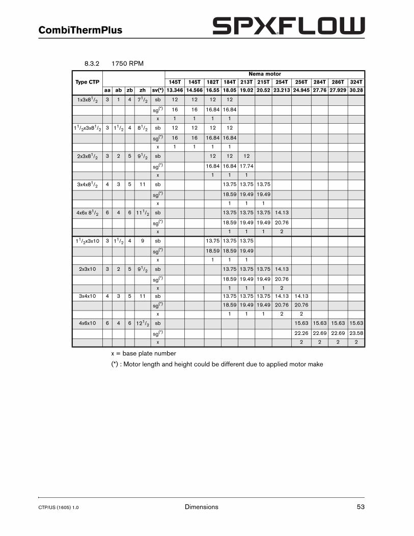
8.3.2 1750 RPM
x = base plate number
(*) : Motor length and height could be different due to applied motor make
pe CTP
Nema motor
145T 145T 182T 184T 213T 215T 254T 256T 284T 286T 324T
aa ab zb zh sv(*) 13.346 14.566 16.55 18.05 19.02 20.52 23.213 24.945 27.76 27.929 30.28
x3x81/2 3 1 4 71/2 sb 12 12 12 12
sg(*) 16 16 16.84 16.84
x 1 1 1 1
/2x3x81/2 3 11/2 4 81/2 sb 12 12 12 12
sg(*) 16 16 16.84 16.84
x 1 1 1 1
x3x81/2 3 2 5 91/2 sb 12 12 12
sg(*) 16.84 16.84 17.74
x 1 1 1
x4x81/2 4 3 5 11 sb 13.75 13.75 13.75
sg(*) 18.59 19.49 19.49
x 1 1 1
x6x 81/2 6 4 6 111/2 sb 13.75 13.75 13.75 14.13
sg(*) 18.59 19.49 19.49 20.76
x 1 1 1 21/2x3x10 3 11/2 4 9 sb 13.75 13.75 13.75
sg(*) 18.59 18.59 19.49
x 1 1 1
2x3x10 3 2 5 91/2 sb 13.75 13.75 13.75 14.13
sg(*) 18.59 19.49 19.49 20.76
x 1 1 1 2
3x4x10 4 3 5 11 sb 13.75 13.75 13.75 14.13 14.13
sg(*) 18.59 19.49 19.49 20.76 20.76
x 1 1 1 2 2
4x6x10 6 4 6 121/2 sb 15.63 15.63 15.63 15.63
sg(*) 22.26 22.69 22.69 23.58
x 2 2 2 2
Dimensions 53
54
Type CT
1x3x81/
11/2x3x81
2x3x81/
3x4x81/
4x6x 81/
11/2x3x1
2x3x10
3x4x10
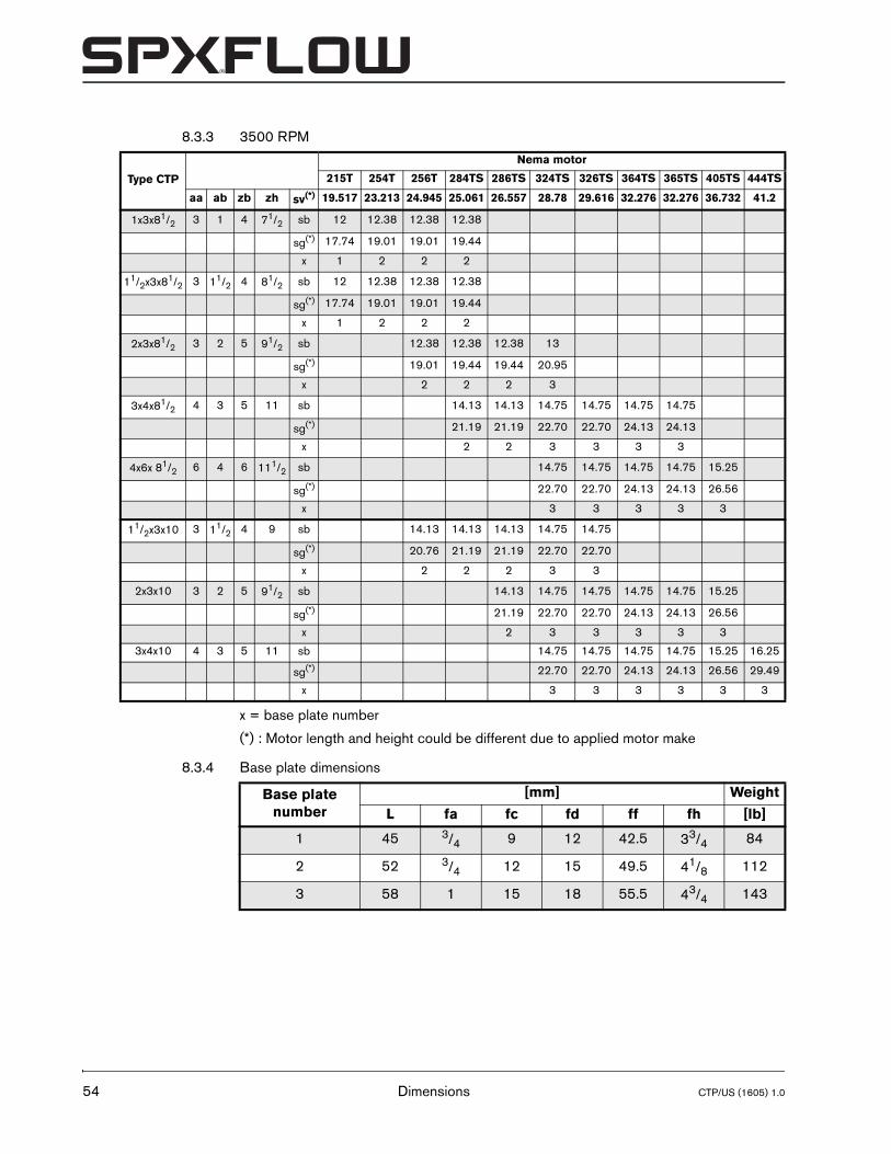
8.3.3 3500 RPM
x = base plate number
(*) : Motor length and height could be different due to applied motor make
8.3.4 Base plate dimensions
P
Nema motor
215T 254T 256T 284TS 286TS 324TS 326TS 364TS 365TS 405TS 444TS
aa ab zb zh sv(*) 19.517 23.213 24.945 25.061 26.557 28.78 29.616 32.276 32.276 36.732 41.2
2 3 1 4 71/2 sb 12 12.38 12.38 12.38
sg(*) 17.74 19.01 19.01 19.44
x 1 2 2 2
/2 3 11/2 4 81/2 sb 12 12.38 12.38 12.38
sg(*) 17.74 19.01 19.01 19.44
x 1 2 2 2
2 3 2 5 91/2 sb 12.38 12.38 12.38 13
sg(*) 19.01 19.44 19.44 20.95
x 2 2 2 3
2 4 3 5 11 sb 14.13 14.13 14.75 14.75 14.75 14.75
sg(*) 21.19 21.19 22.70 22.70 24.13 24.13
x 2 2 3 3 3 3
2 6 4 6 111/2 sb 14.75 14.75 14.75 14.75 15.25
sg(*) 22.70 22.70 24.13 24.13 26.56
x 3 3 3 3 3
0 3 11/2 4 9 sb 14.13 14.13 14.13 14.75 14.75
sg(*) 20.76 21.19 21.19 22.70 22.70
x 2 2 2 3 3
3 2 5 91/2 sb 14.13 14.75 14.75 14.75 14.75 15.25
sg(*) 21.19 22.70 22.70 24.13 24.13 26.56
x 2 3 3 3 3 3
4 3 5 11 sb 14.75 14.75 14.75 14.75 15.25 16.25
sg(*) 22.70 22.70 24.13 24.13 26.56 29.49
x 3 3 3 3 3 3
Base plate number
[mm] Weight
L fa fc fd ff fh [lb]
1 45 3/4 9 12 42.5 33/4 84
2 52 3/4 12 15 49.5 41/8 112
3 58 1 15 18 55.5 43/4 143
Dimensions CTP/US (1605) 1.0
CTP/US (1605) 1.0
CombiThermPlus
4.5
zb
ab
aa
1.25
Ofa
BZ
BP
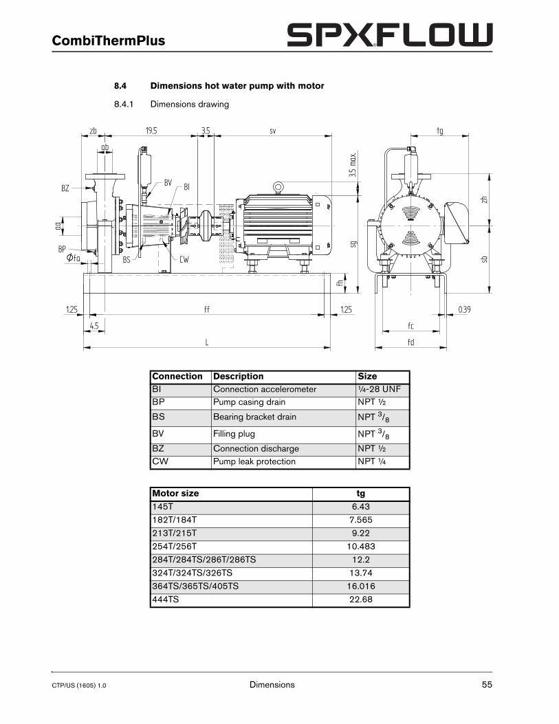
8.4 Dimensions hot water pump with motor
8.4.1 Dimensions drawing
Connection Description SizeBI Connection accelerometer ¼-28 UNFBP Pump casing drain NPT ½
BS Bearing bracket drain NPT 3/8
BV Filling plug NPT 3/8BZ Connection discharge NPT ½CW Pump leak protection NPT ¼
Motor size tg145T 6.43182T/184T 7.565213T/215T 9.22254T/256T 10.483284T/284TS/286T/286TS 12.2324T/324TS/326TS 13.74364TS/365TS/405TS 16.016444TS 22.68
fhfd
19.5 3.5 sv tg
0.39
sbzh
L
fc
ff 1.25
sg3.5
max
.
BS CW
BIBV
Dimensions 55
56
Ty
1
11
2
3
4
1
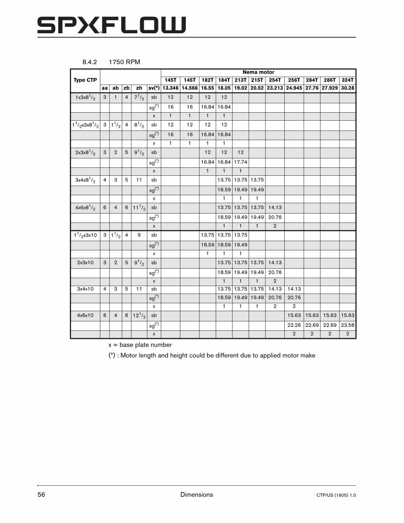
8.4.2 1750 RPM
x = base plate number
(*) : Motor length and height could be different due to applied motor make
pe CTP
Nema motor
145T 145T 182T 184T 213T 215T 254T 256T 284T 286T 324T
aa ab zb zh sv(*) 13.346 14.566 16.55 18.05 19.02 20.52 23.213 24.945 27.76 27.929 30.28
x3x81/2 3 1 4 71/2 sb 12 12 12 12
sg(*) 16 16 16.84 16.84
x 1 1 1 1
/2x3x81/2 3 11/2 4 81/2 sb 12 12 12 12
sg(*) 16 16 16.84 16.84
x 1 1 1 1
x3x81/2 3 2 5 91/2 sb 12 12 12
sg(*) 16.84 16.84 17.74
x 1 1 1
x4x81/2 4 3 5 11 sb 13.75 13.75 13.75
sg(*) 18.59 19.49 19.49
x 1 1 1
x6x81/2 6 4 6 111/2 sb 13.75 13.75 13.75 14.13
sg(*) 18.59 19.49 19.49 20.76
x 1 1 1 21/2x3x10 3 11/2 4 9 sb 13.75 13.75 13.75
sg(*) 18.59 18.59 19.49
x 1 1 1
2x3x10 3 2 5 91/2 sb 13.75 13.75 13.75 14.13
sg(*) 18.59 19.49 19.49 20.76
x 1 1 1 2
3x4x10 4 3 5 11 sb 13.75 13.75 13.75 14.13 14.13
sg(*) 18.59 19.49 19.49 20.76 20.76
x 1 1 1 2 2
4x6x10 6 4 6 121/2 sb 15.63 15.63 15.63 15.63
sg(*) 22.26 22.69 22.69 23.58
x 2 2 2 2
Dimensions CTP/US (1605) 1.0
CTP/US (1605) 1.0
CombiThermPlus
Type CT
1x3x81
11/2x3x8
2x3x81
3x4x81
4x6x81
11/2x3x
2x3x10
3x4x10
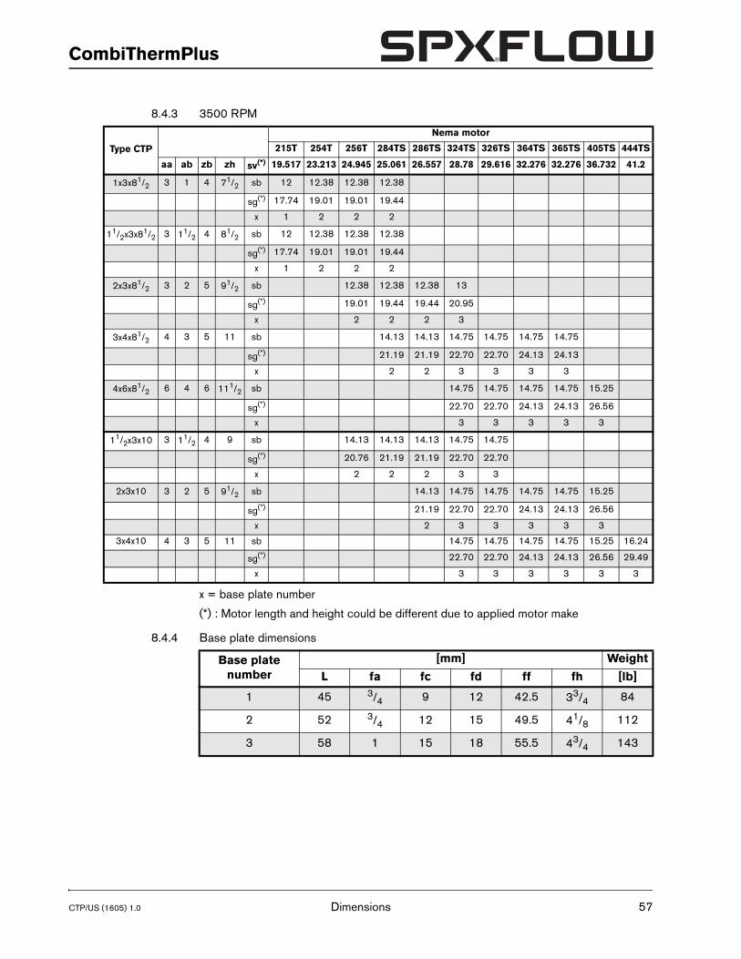
8.4.3 3500 RPM
x = base plate number
(*) : Motor length and height could be different due to applied motor make
8.4.4 Base plate dimensions
P
Nema motor
215T 254T 256T 284TS 286TS 324TS 326TS 364TS 365TS 405TS 444TS
aa ab zb zh sv(*) 19.517 23.213 24.945 25.061 26.557 28.78 29.616 32.276 32.276 36.732 41.2
/2 3 1 4 71/2 sb 12 12.38 12.38 12.38
sg(*) 17.74 19.01 19.01 19.44
x 1 2 2 21/2 3 11/2 4 81/2 sb 12 12.38 12.38 12.38
sg(*) 17.74 19.01 19.01 19.44
x 1 2 2 2
/2 3 2 5 91/2 sb 12.38 12.38 12.38 13
sg(*) 19.01 19.44 19.44 20.95
x 2 2 2 3
/2 4 3 5 11 sb 14.13 14.13 14.75 14.75 14.75 14.75
sg(*) 21.19 21.19 22.70 22.70 24.13 24.13
x 2 2 3 3 3 3
/2 6 4 6 111/2 sb 14.75 14.75 14.75 14.75 15.25
sg(*) 22.70 22.70 24.13 24.13 26.56
x 3 3 3 3 3
10 3 11/2 4 9 sb 14.13 14.13 14.13 14.75 14.75
sg(*) 20.76 21.19 21.19 22.70 22.70
x 2 2 2 3 3
3 2 5 91/2 sb 14.13 14.75 14.75 14.75 14.75 15.25
sg(*) 21.19 22.70 22.70 24.13 24.13 26.56
x 2 3 3 3 3 3
4 3 5 11 sb 14.75 14.75 14.75 14.75 15.25 16.24
sg(*) 22.70 22.70 24.13 24.13 26.56 29.49
x 3 3 3 3 3 3
Base plate number
[mm] Weight
L fa fc fd ff fh [lb]
1 45 3/4 9 12 42.5 33/4 84
2 52 3/4 12 15 49.5 41/8 112
3 58 1 15 18 55.5 43/4 143
Dimensions 57
58
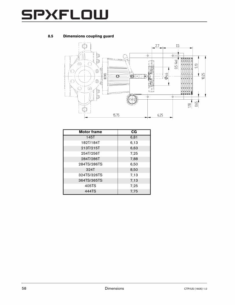
8.5 Dimensions coupling guard
Motor frame CG145T 6,81
182T/184T 6,13213T/215T 6,63254T/256T 7,25284T/286T 7,88
284TS/286TS 6,50324T 8,50
324TS/326TS 7,13364TS/365TS 7,13
405TS 7,25444TS 7,75
1.18
CG2.7
4.6O
0.5 (4
x)
15.75 6.25
0.65
5.13
10.25
Dimensions CTP/US (1605) 1.0
CTP/US (1605) 1.0
CombiThermPlus
9 Parts
9.1 Ordering parts
9.1.1 Order form
When ordering parts always quote the following data:
1 Your address.
2 The quantity, the item number and the description of the part.
3 The pump number. The pump number is stated on the label on the cover of this manual and on the type plate of the pump.
4 In the event of different electric motor voltage you should state the correct voltage.
9.1.2 Recommended spare parts
Parts marked with a * are recommended spare parts.
Parts 59
60
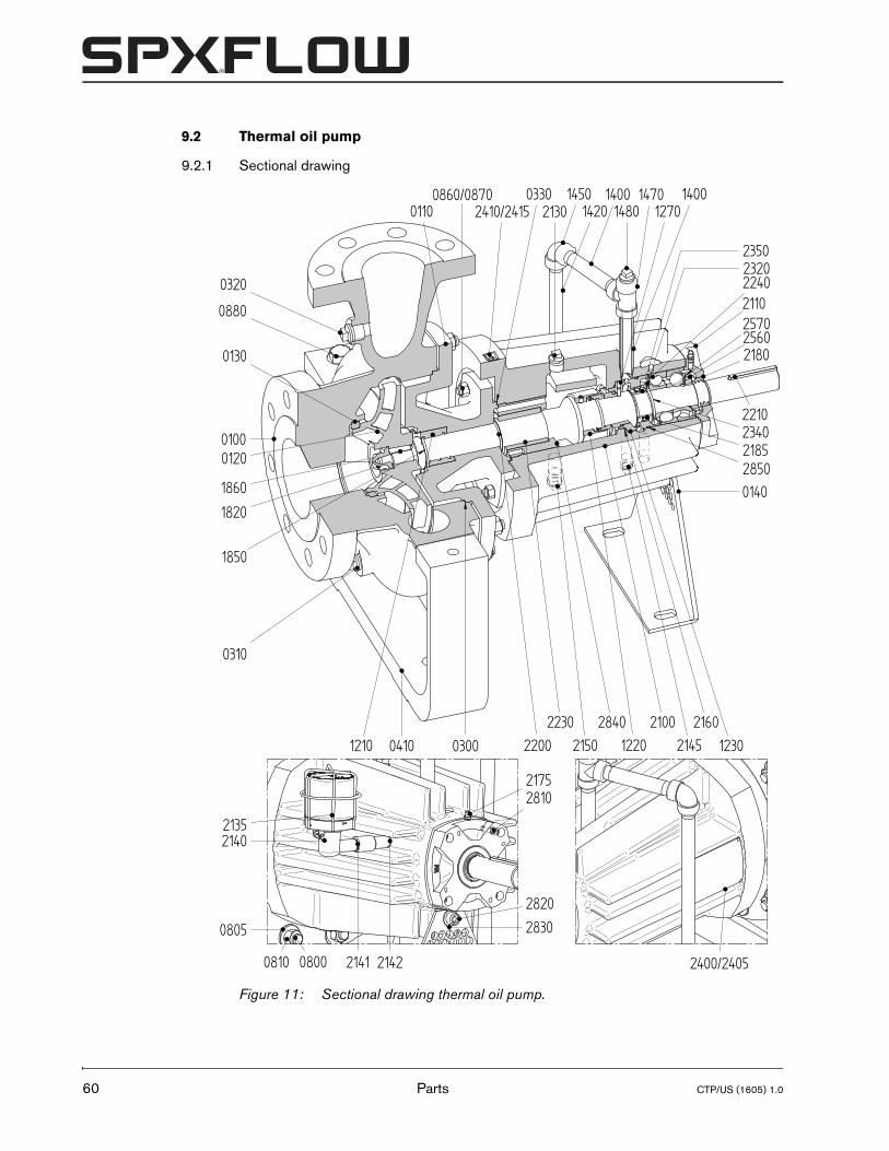
9.2 Thermal oil pump
9.2.1 Sectional drawing
Figure 11: Sectional drawing thermal oil pump.
0100
0140
2400/24050800
1820
1860
0310
0320
0860/08702130
2820
2830
2810
2110
2175
2135
2141 2142
0120
0110
0880
2180
2230 2100 216012300410 0300 2200 2150
0330 14501420
14001480
1470
25602570
2240
2340
28502185
23202350
1400
12202840
21451210
1850
0130
2410/2415
2140
1270
2210
0805
0810
Parts CTP/US (1605) 1.0
CTP/US (1605) 1.0
CombiThermPlus
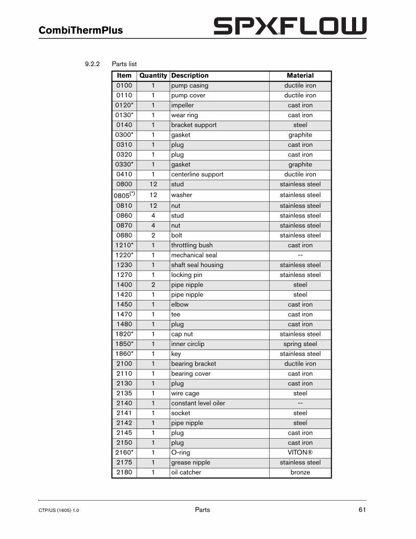
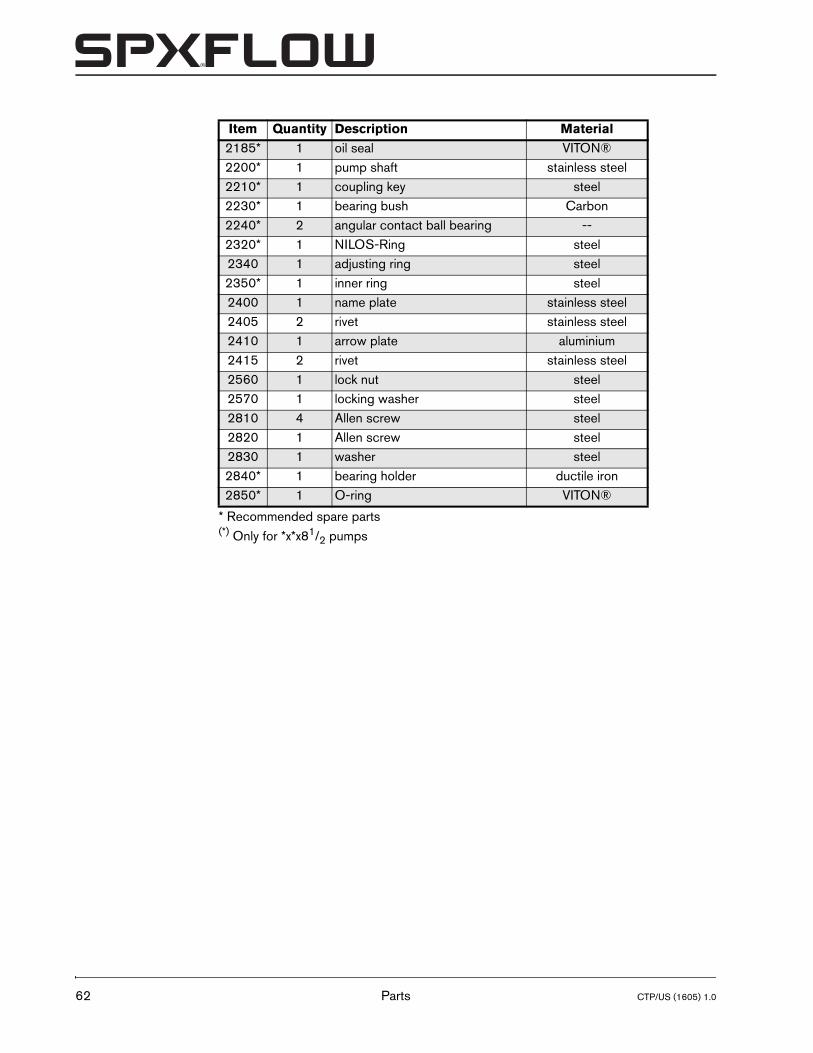
9.2.2 Parts list
Item Quantity Description Material0100 1 pump casing ductile iron0110 1 pump cover ductile iron0120* 1 impeller cast iron0130* 1 wear ring cast iron0140 1 bracket support steel0300* 1 gasket graphite0310 1 plug cast iron0320 1 plug cast iron0330* 1 gasket graphite0410 1 centerline support ductile iron0800 12 stud stainless steel
0805(*) 12 washer stainless steel
0810 12 nut stainless steel0860 4 stud stainless steel0870 4 nut stainless steel0880 2 bolt stainless steel1210* 1 throttling bush cast iron1220* 1 mechanical seal --1230 1 shaft seal housing stainless steel1270 1 locking pin stainless steel1400 2 pipe nipple steel1420 1 pipe nipple steel1450 1 elbow cast iron1470 1 tee cast iron1480 1 plug cast iron1820* 1 cap nut stainless steel1850* 1 inner circlip spring steel1860* 1 key stainless steel2100 1 bearing bracket ductile iron2110 1 bearing cover cast iron2130 1 plug cast iron2135 1 wire cage steel2140 1 constant level oiler --2141 1 socket steel2142 1 pipe nipple steel2145 1 plug cast iron2150 1 plug cast iron2160* 1 O-ring VITON®2175 1 grease nipple stainless steel2180 1 oil catcher bronze
Parts 61
62
* Recommended spare parts(*) Only for *x*x81/2 pumps
2185* 1 oil seal VITON®2200* 1 pump shaft stainless steel2210* 1 coupling key steel2230* 1 bearing bush Carbon2240* 2 angular contact ball bearing --2320* 1 NILOS-Ring steel2340 1 adjusting ring steel2350* 1 inner ring steel2400 1 name plate stainless steel2405 2 rivet stainless steel2410 1 arrow plate aluminium2415 2 rivet stainless steel2560 1 lock nut steel2570 1 locking washer steel2810 4 Allen screw steel2820 1 Allen screw steel2830 1 washer steel2840* 1 bearing holder ductile iron2850* 1 O-ring VITON®
Item Quantity Description Material
Parts CTP/US (1605) 1.0
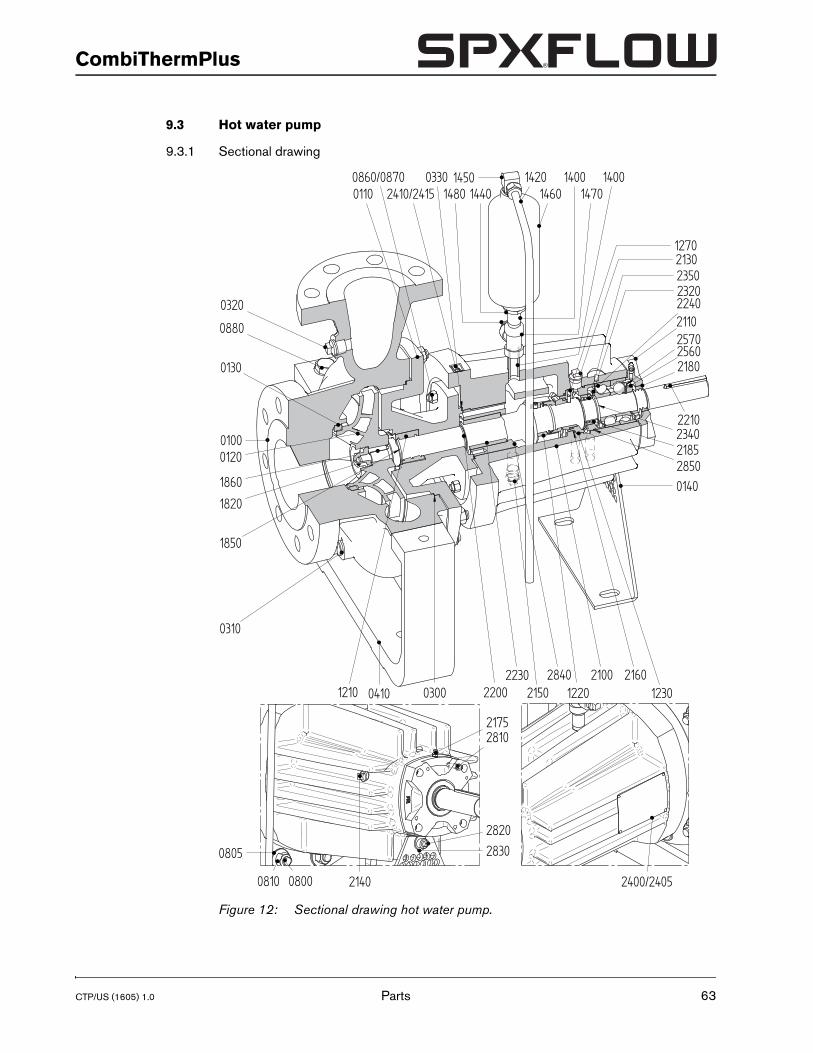
CTP/US (1605) 1.0
CombiThermPlus
9.3 Hot water pump
9.3.1 Sectional drawing
Figure 12: Sectional drawing hot water pump.
0100
0140
0800
1820
1860
0310
0320
2130
2820
2830
2810
2110
2175
2140
0120
0110
0880
2180
2230 2100 216012300410 0300 2200 2150
0330 1450 1420 14001480 1470
25602570
2240
2340
28502185
23202350
1400
12202840
1210
1850
0130
1270
2210
0805
0810
2410/24150860/0870
14601440
2400/2405
Parts 63
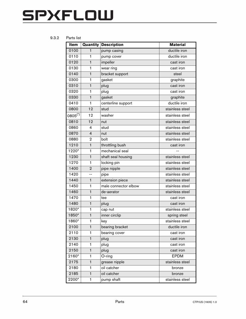
64
9.3.2 Parts list
Item Quantity Description Material0100 1 pump casing ductile iron0110 1 pump cover ductile iron0120 1 impeller cast iron0130 1 wear ring cast iron0140 1 bracket support steel0300 1 gasket graphite0310 1 plug cast iron0320 1 plug cast iron0330 1 gasket graphite0410 1 centerline support ductile iron0800 12 stud stainless steel
0805(*) 12 washer stainless steel
0810 12 nut stainless steel0860 4 stud stainless steel0870 4 nut stainless steel0880 2 bolt stainless steel1210 1 throttling bush cast iron1220* 1 mechanical seal --1230 1 shaft seal housing stainless steel1270 1 locking pin stainless steel1400 2 pipe nipple stainless steel1420 -- pipe stainless steel1440 1 extension piece stainless steel1450 1 male connector elbow stainless steel1460 1 de-aerator stainless steel1470 1 tee cast iron1480 1 plug cast iron1820* 1 cap nut stainless steel1850* 1 inner circlip spring steel1860* 1 key stainless steel2100 1 bearing bracket ductile iron2110 1 bearing cover cast iron2130 1 plug cast iron2140 1 plug cast iron2150 1 plug cast iron2160* 1 O-ring EPDM2175 1 grease nipple stainless steel2180 1 oil catcher bronze2185 1 oil catcher bronze2200* 1 pump shaft stainless steel
Parts CTP/US (1605) 1.0
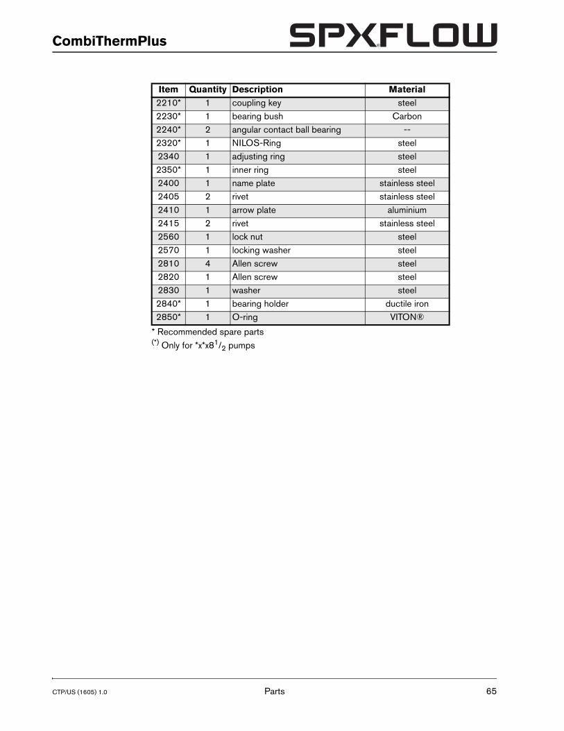
CTP/US (1605) 1.0
CombiThermPlus
* Recommended spare parts(*) Only for *x*x81/2 pumps
2210* 1 coupling key steel2230* 1 bearing bush Carbon2240* 2 angular contact ball bearing --2320* 1 NILOS-Ring steel2340 1 adjusting ring steel2350* 1 inner ring steel2400 1 name plate stainless steel2405 2 rivet stainless steel2410 1 arrow plate aluminium2415 2 rivet stainless steel2560 1 lock nut steel2570 1 locking washer steel2810 4 Allen screw steel2820 1 Allen screw steel2830 1 washer steel2840* 1 bearing holder ductile iron2850* 1 O-ring VITON®
Item Quantity Description Material
Parts 65
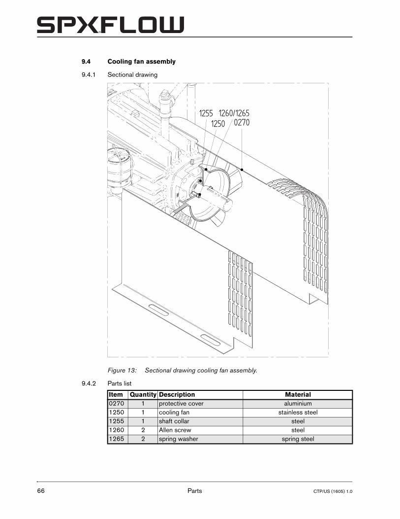
66
9.4 Cooling fan assembly
9.4.1 Sectional drawing
9.4.2 Parts list
Figure 13: Sectional drawing cooling fan assembly.
Item Quantity Description Material0270 1 protective cover aluminium1250 1 cooling fan stainless steel1255 1 shaft collar steel1260 2 Allen screw steel1265 2 spring washer spring steel
027012501255 1260/1265
Parts CTP/US (1605) 1.0
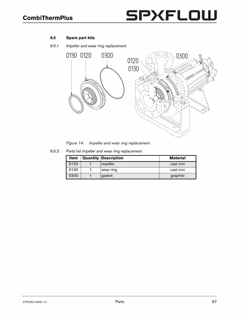
CTP/US (1605) 1.0
CombiThermPlus
9.5 Spare part kits
9.5.1 Impeller and wear ring replacement
9.5.2 Parts list impeller and wear ring replacement
Figure 14: Impeller and wear ring replacement.
Item Quantity Description Material0120 1 impeller cast iron0130 1 wear ring cast iron0300 1 gasket graphite
0130
03000120
030001200130
Parts 67
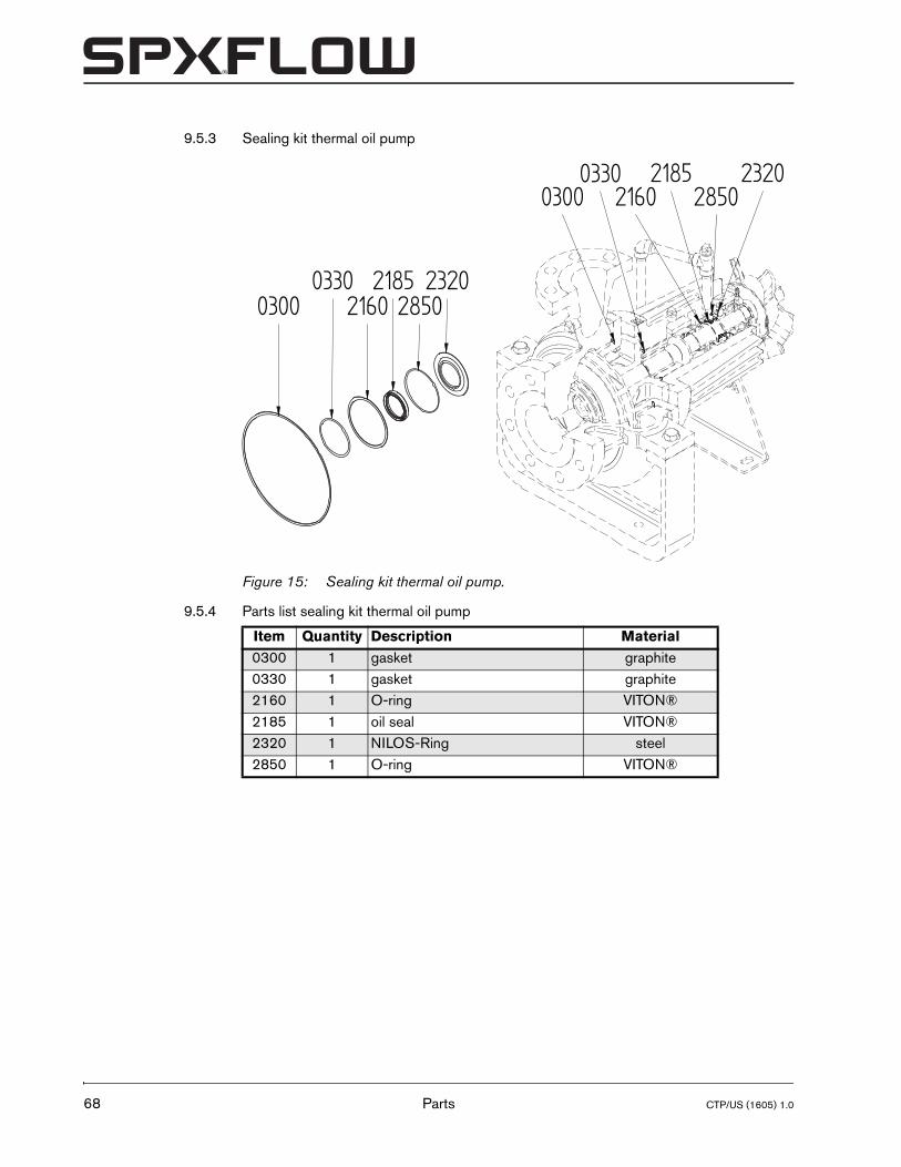
68
9.5.3 Sealing kit thermal oil pump
9.5.4 Parts list sealing kit thermal oil pump
Figure 15: Sealing kit thermal oil pump.
Item Quantity Description Material0300 1 gasket graphite0330 1 gasket graphite2160 1 O-ring VITON®2185 1 oil seal VITON®2320 1 NILOS-Ring steel2850 1 O-ring VITON®
030023200330
0300 28500330
28502185
2160
232021852160
Parts CTP/US (1605) 1.0
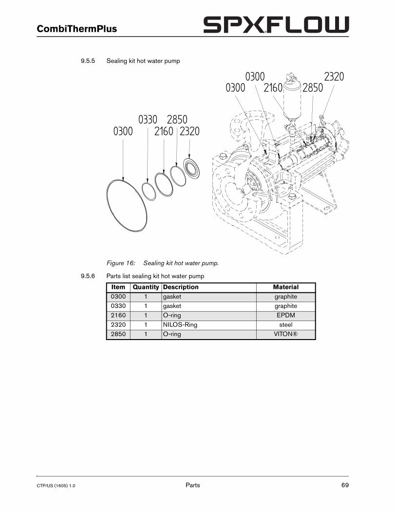
CTP/US (1605) 1.0
CombiThermPlus
9.5.5 Sealing kit hot water pump
9.5.6 Parts list sealing kit hot water pump
Figure 16: Sealing kit hot water pump.
Item Quantity Description Material0300 1 gasket graphite0330 1 gasket graphite2160 1 O-ring EPDM2320 1 NILOS-Ring steel2850 1 O-ring VITON®
03002320
030028500330
28502160
23202160
0300
Parts 69
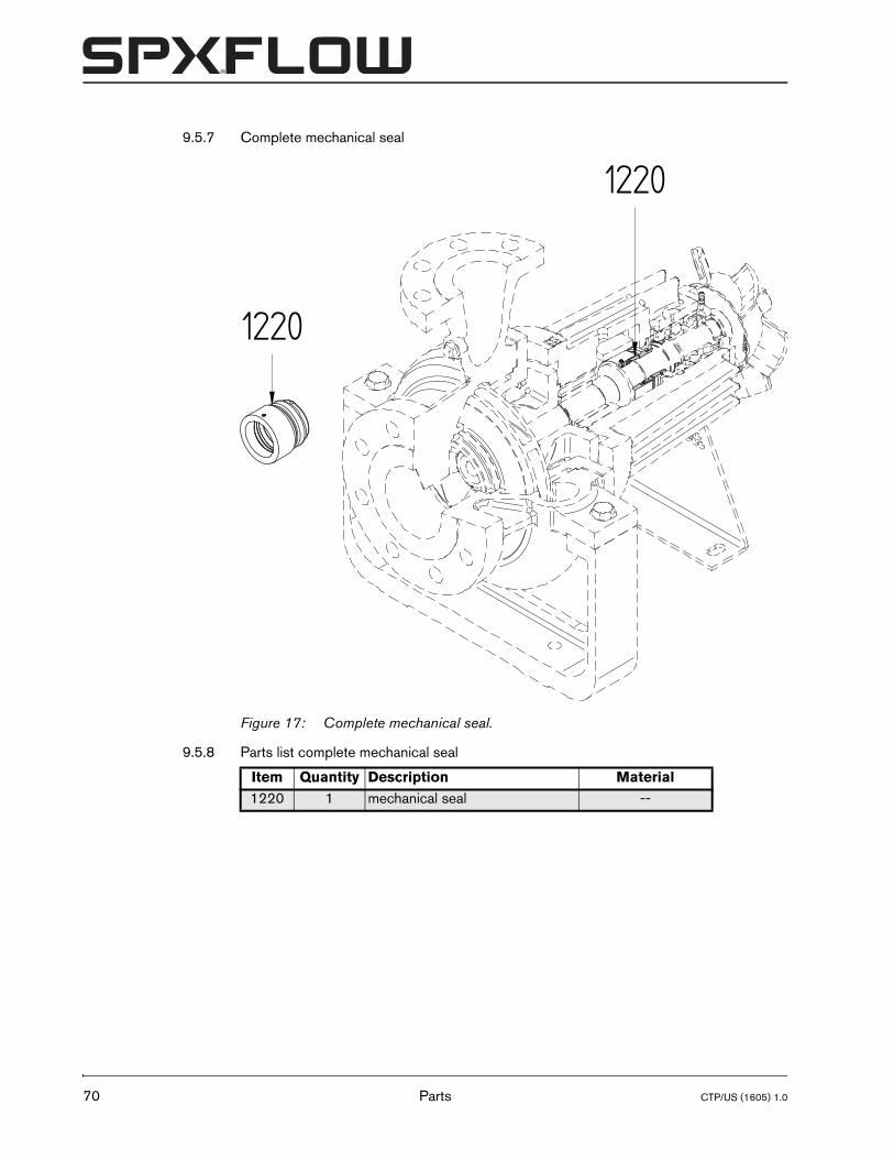
70
9.5.7 Complete mechanical seal
9.5.8 Parts list complete mechanical seal
Figure 17: Complete mechanical seal.
Item Quantity Description Material1220 1 mechanical seal --
1220
1220
Parts CTP/US (1605) 1.0
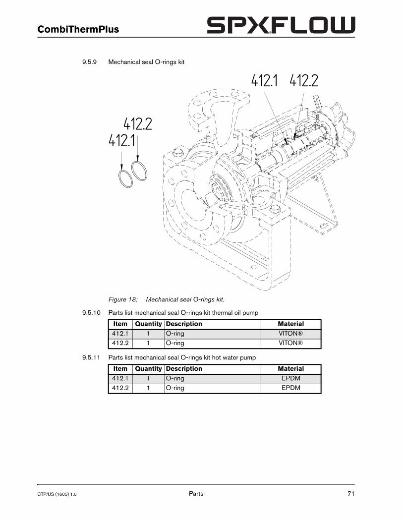
CTP/US (1605) 1.0
CombiThermPlus
9.5.9 Mechanical seal O-rings kit
9.5.10 Parts list mechanical seal O-rings kit thermal oil pump
9.5.11 Parts list mechanical seal O-rings kit hot water pump
Figure 18: Mechanical seal O-rings kit.
Item Quantity Description Material412.1 1 O-ring VITON®412.2 1 O-ring VITON®
Item Quantity Description Material412.1 1 O-ring EPDM412.2 1 O-ring EPDM
412.2
412.2
412.1
412.1
Parts 71

72
9.5.12 Ball bearings
9.5.13 Parts list ball bearings
Figure 19: Ball bearings.
Item Quantity Description Material2240 2 angular contact ball bearing --
2240
2240
Parts CTP/US (1605) 1.0
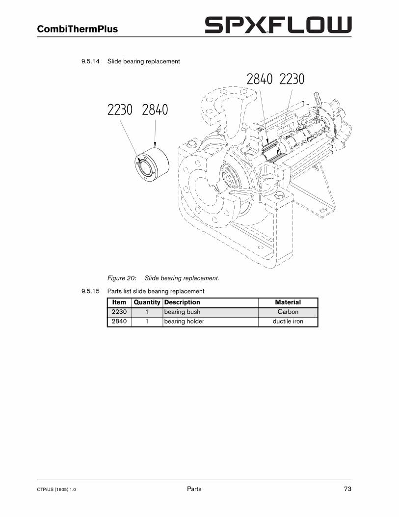
CTP/US (1605) 1.0
CombiThermPlus
9.5.14 Slide bearing replacement
9.5.15 Parts list slide bearing replacement
Figure 20: Slide bearing replacement.
Item Quantity Description Material2230 1 bearing bush Carbon2840 1 bearing holder ductile iron
2230
2840
2840
2230
Parts 73

74
Parts CTP/US (1605) 1.0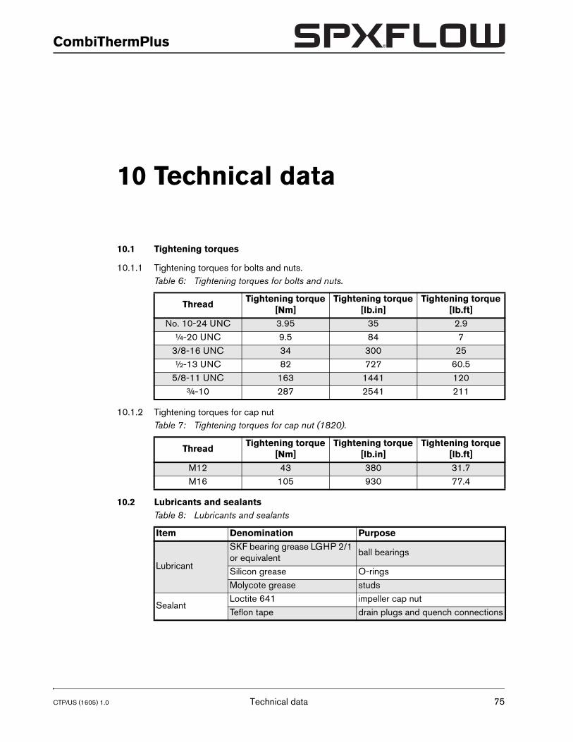
CTP/US (1605) 1.0
CombiThermPlus
10 Technical data
10.1 Tightening torques
10.1.1 Tightening torques for bolts and nuts.
10.1.2 Tightening torques for cap nut
10.2 Lubricants and sealants
Table 6: Tightening torques for bolts and nuts.
ThreadTightening torque
[Nm]Tightening torque
[lb.in]Tightening torque
[lb.ft]No. 10-24 UNC 3.95 35 2.9
¼-20 UNC 9.5 84 73/8-16 UNC 34 300 25½-13 UNC 82 727 60.5
5/8-11 UNC 163 1441 120¾-10 287 2541 211
Table 7: Tightening torques for cap nut (1820).
ThreadTightening torque
[Nm]Tightening torque
[lb.in]Tightening torque
[lb.ft]M12 43 380 31.7M16 105 930 77.4
Table 8: Lubricants and sealants
Item Denomination Purpose
Lubricant
SKF bearing grease LGHP 2/1 or equivalent
ball bearings
Silicon grease O-ringsMolycote grease studs
SealantLoctite 641 impeller cap nutTeflon tape drain plugs and quench connections
Technical data 75
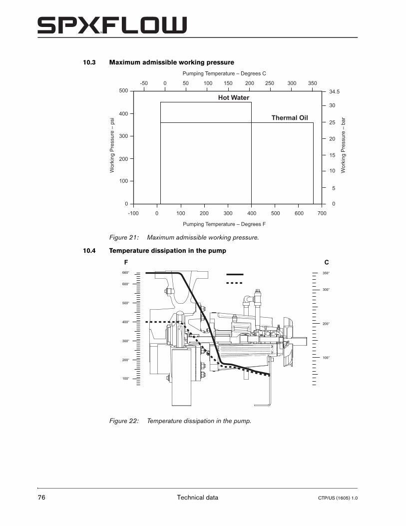
76
10.3 Maximum admissible working pressure
10.4 Temperature dissipation in the pump
Figure 21: Maximum admissible working pressure.
Figure 22: Temperature dissipation in the pump.
-100 0 100 200 300 400 500 600 700
-50 50 100
100
200
300
400
500
0 0
5
10
15
20
25
30
34.5150 200 250 300 3500
Pumping Temperature – Degrees F
Wor
king
Pre
ssur
e –
psi
Wor
king
Pre
ssur
e –
bar
Pumping Temperature – Degrees C
Thermal Oil
Hot Water
100°
100°
200°
300°
350°
200°
300°
400°
500°
600°
660°
F C
Technical data CTP/US (1605) 1.0
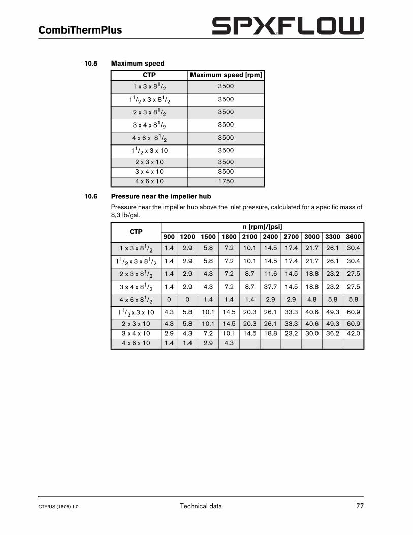
CTP/US (1605) 1.0
CombiThermPlus
10.5 Maximum speed
10.6 Pressure near the impeller hub
Pressure near the impeller hub above the inlet pressure, calculated for a specific mass of 8,3 lb/gal.
CTP Maximum speed [rpm]
1 x 3 x 81/2 3500
11/2 x 3 x 81/2 3500
2 x 3 x 81/2 3500
3 x 4 x 81/2 3500
4 x 6 x 81/2 3500
11/2 x 3 x 10 3500
2 x 3 x 10 35003 x 4 x 10 35004 x 6 x 10 1750
CTPn [rpm]/[psi]
900 1200 1500 1800 2100 2400 2700 3000 3300 3600
1 x 3 x 81/2 1.4 2.9 5.8 7.2 10.1 14.5 17.4 21.7 26.1 30.4
11/2 x 3 x 81/2 1.4 2.9 5.8 7.2 10.1 14.5 17.4 21.7 26.1 30.4
2 x 3 x 81/2 1.4 2.9 4.3 7.2 8.7 11.6 14.5 18.8 23.2 27.5
3 x 4 x 81/2 1.4 2.9 4.3 7.2 8.7 37.7 14.5 18.8 23.2 27.5
4 x 6 x 81/2 0 0 1.4 1.4 1.4 2.9 2.9 4.8 5.8 5.8
11/2 x 3 x 10 4.3 5.8 10.1 14.5 20.3 26.1 33.3 40.6 49.3 60.9
2 x 3 x 10 4.3 5.8 10.1 14.5 20.3 26.1 33.3 40.6 49.3 60.93 x 4 x 10 2.9 4.3 7.2 10.1 14.5 18.8 23.2 30.0 36.2 42.04 x 6 x 10 1.4 1.4 2.9 4.3
Technical data 77
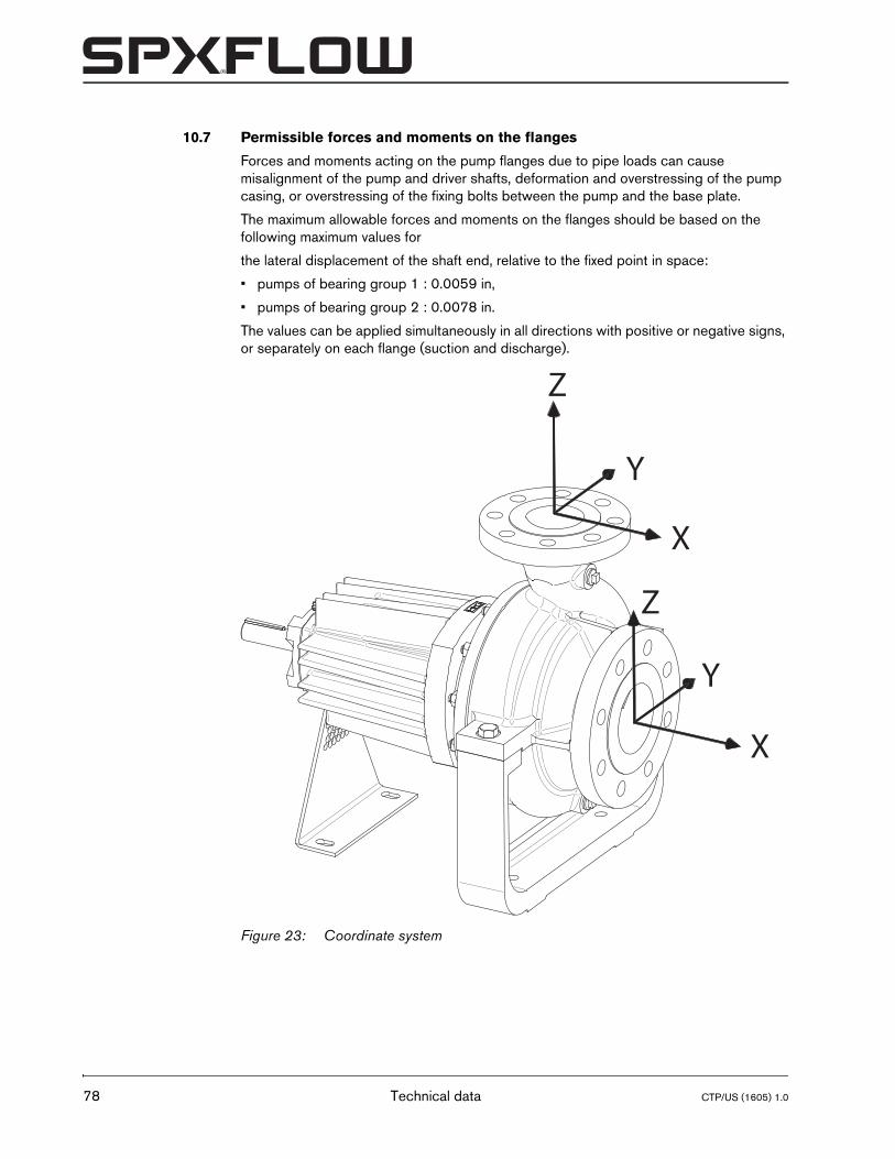
78
10.7 Permissible forces and moments on the flanges
Forces and moments acting on the pump flanges due to pipe loads can cause misalignment of the pump and driver shafts, deformation and overstressing of the pump casing, or overstressing of the fixing bolts between the pump and the base plate.
The maximum allowable forces and moments on the flanges should be based on the following maximum values for
the lateral displacement of the shaft end, relative to the fixed point in space:
• pumps of bearing group 1 : 0.0059 in,
• pumps of bearing group 2 : 0.0078 in.
The values can be applied simultaneously in all directions with positive or negative signs, or separately on each flange (suction and discharge).
Figure 23: Coordinate system
X
X
Y
Z
Y
Z
Technical data CTP/US (1605) 1.0
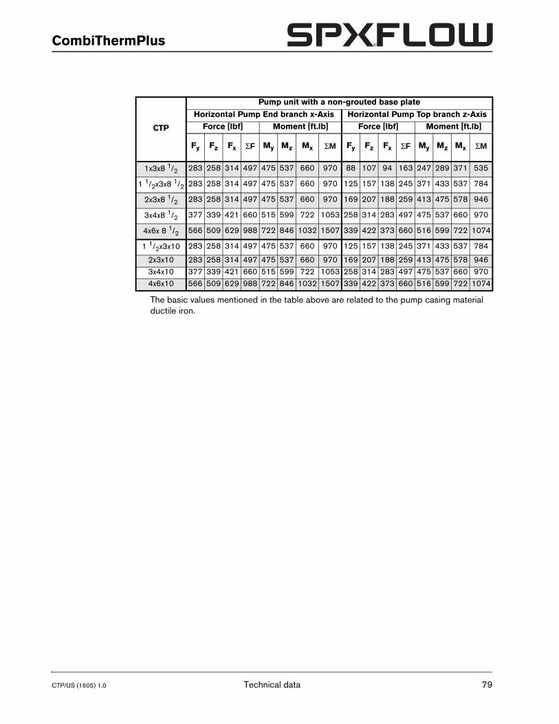
CTP/US (1605) 1.0
CombiThermPlus
The basic values mentioned in the table above are related to the pump casing material ductile iron.
CTP
Pump unit with a non-grouted base plate
Horizontal Pump End branch x-Axis Horizontal Pump Top branch z-Axis
Force [lbf] Moment [ft.lb] Force [lbf] Moment [ft.lb]
Fy Fz Fx ΣF My Mz Mx ΣM Fy Fz Fx ΣF My Mz Mx ΣM
1x3x8 1/2 283 258 314 497 475 537 660 970 88 107 94 163 247 289 371 535
1 1/2x3x8 1/2 283 258 314 497 475 537 660 970 125 157 138 245 371 433 537 784
2x3x8 1/2 283 258 314 497 475 537 660 970 169 207 188 259 413 475 578 946
3x4x8 1/2 377 339 421 660 515 599 722 1053 258 314 283 497 475 537 660 970
4x6x 8 1/2 566 509 629 988 722 846 1032 1507 339 422 373 660 516 599 722 1074
1 1/2x3x10 283 258 314 497 475 537 660 970 125 157 138 245 371 433 537 784
2x3x10 283 258 314 497 475 537 660 970 169 207 188 259 413 475 578 9463x4x10 377 339 421 660 515 599 722 1053 258 314 283 497 475 537 660 9704x6x10 566 509 629 988 722 846 1032 1507 339 422 373 660 516 599 722 1074
Technical data 79
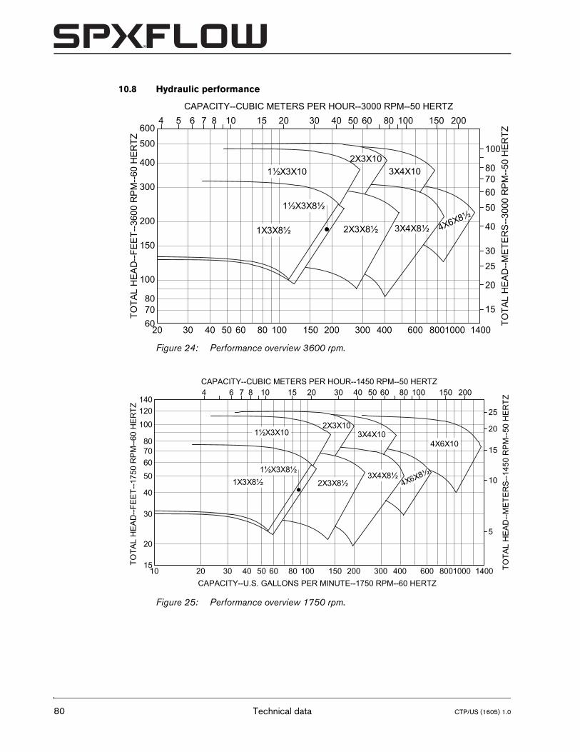
80
10.8 Hydraulic performance
Figure 24: Performance overview 3600 rpm.
Figure 25: Performance overview 1750 rpm.
4X6X8½3X4X8½
2X3X10
7080
100
500
200
300
400
15020 30 40 50 60 80 100 200 300 400 1400800600 100060
150
15
20
25
0020518764 10 15 20 30 40 50 60 80 1005
50
607080
100
30
40
TOTA
L H
EA
D--F
EE
T--3
600
RP
M--6
0 H
ER
TZ
CAPACITY--CUBIC METERS PER HOUR--3000 RPM--50 HERTZ
TOTA
L H
EA
D--M
ETE
RS
--300
0 R
PM
--50
HE
RTZ
1X3X8½
1½X3X8½
1½X3X10
2X3X8½
3X4X10
600
50
607080
100
6 7 8
150
150 2004
15
20
30
40
120
10
15
20
25
5
10 15 20 30 40 50 60 80 100140
10 20 30 40 50 60 80 100 200 300 400 1400800600 1000CAPACITY--U.S. GALLONS PER MINUTE--1750 RPM--60 HERTZ
CAPACITY--CUBIC METERS PER HOUR--1450 RPM--50 HERTZ
TOTA
L H
EA
D--F
EE
T--1
750
RP
M--6
0 H
ER
TZ
TOTA
L H
EA
D--M
ETE
RS
--145
0 R
PM
--50
HE
RTZ
1X3X8½1½X3X8½
1½X3X10
2X3X8½
2X3X10
4X6X8½
4X6X103X4X10
3X4X8½
Technical data CTP/US (1605) 1.0
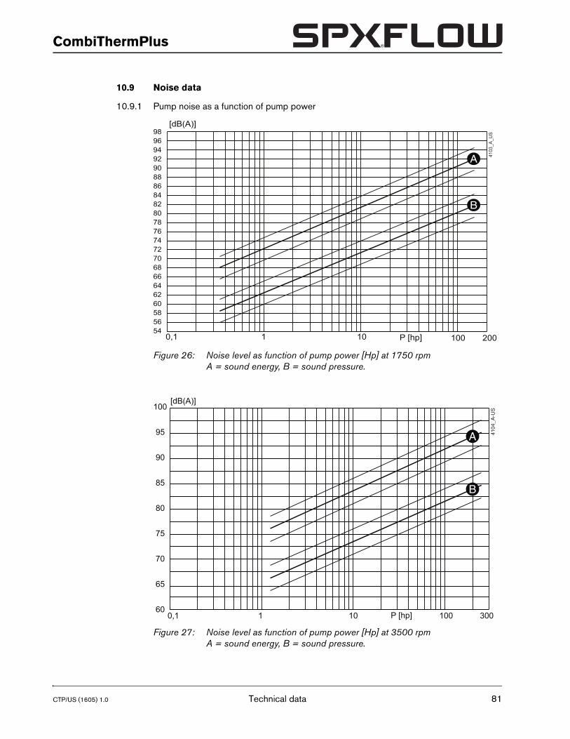
CTP/US (1605) 1.0
CombiThermPlus
10.9 Noise data
10.9.1 Pump noise as a function of pump power
Figure 26: Noise level as function of pump power [Hp] at 1750 rpmA = sound energy, B = sound pressure.
Figure 27: Noise level as function of pump power [Hp] at 3500 rpmA = sound energy, B = sound pressure.
5456586062646668707274767880828486889092949698
0,1 1 10 100 200P [hp]
[dB(A)]
A 4103
_A_U
S
B
60
65
70
75
80
85
90
95
100
0,1 1 10 100 300P [hp]
[dB(A)]
4104
_A-U
S
A
B
Technical data 81
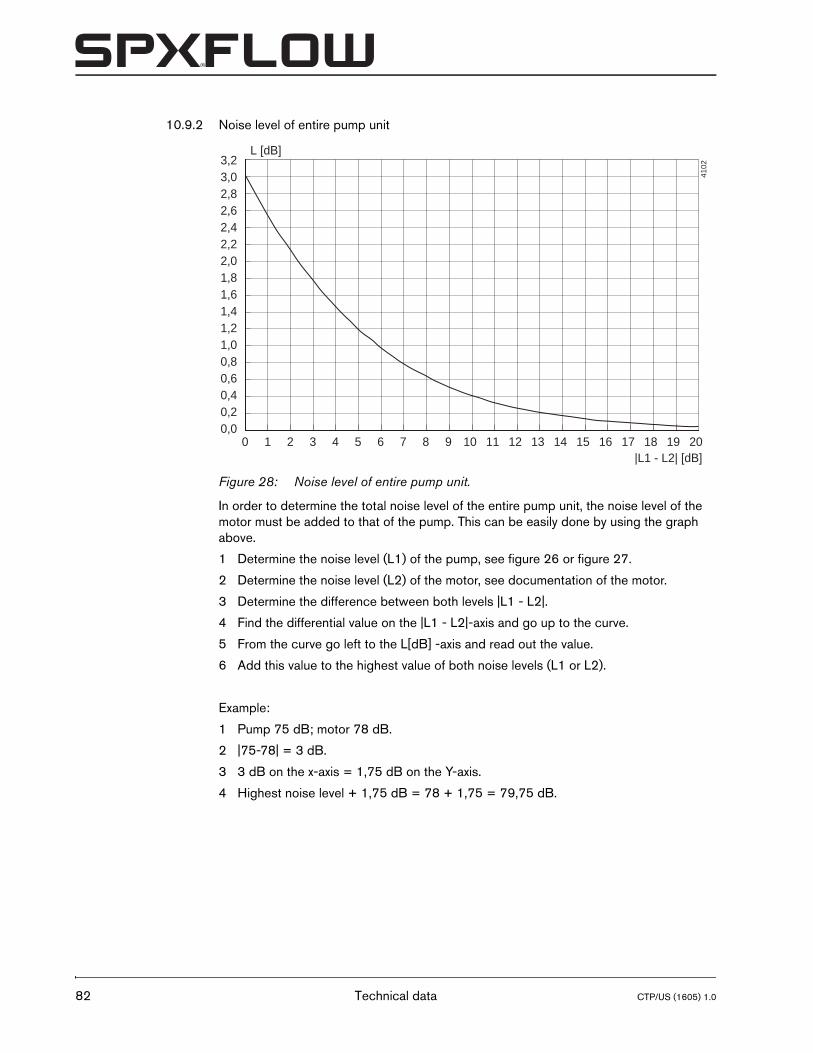
82
10.9.2 Noise level of entire pump unit
In order to determine the total noise level of the entire pump unit, the noise level of the motor must be added to that of the pump. This can be easily done by using the graph above.
1 Determine the noise level (L1) of the pump, see figure 26 or figure 27.
2 Determine the noise level (L2) of the motor, see documentation of the motor.
3 Determine the difference between both levels |L1 - L2|.
4 Find the differential value on the |L1 - L2|-axis and go up to the curve.
5 From the curve go left to the L[dB] -axis and read out the value.
6 Add this value to the highest value of both noise levels (L1 or L2).
Example:
1 Pump 75 dB; motor 78 dB.
2 |75-78| = 3 dB.
3 3 dB on the x-axis = 1,75 dB on the Y-axis.
4 Highest noise level + 1,75 dB = 78 + 1,75 = 79,75 dB.
Figure 28: Noise level of entire pump unit.
4102
L [dB]
|L1 - L2| [dB]0 1 2 3 4 5 6 7 8 9 10 11 12 13 14 15 16 17 18 19 20
3,23,02,82,62,42,22,01,81,61,41,21,00,80,60,40,20,0
Technical data CTP/US (1605) 1.0
CTP/US (1605) 1.0
CombiThermPlus
Index
AAccessories . . . . . . . . . . . . . . . . . . . . . . . . .21Application area . . . . . . . . . . . . . . . . . . . . .17Applications . . . . . . . . . . . . . . . . . . . . . . . . .15
BBack-Pull-Out system . . . . . . . . . . . . . . . .35Back-Pull-Out unit
assembling . . . . . . . . . . . . . . . . . . . . . .35disassembly . . . . . . . . . . . . . . . . . . . . .35
Bearing assemblyremoving . . . . . . . . . . . . . . . . . . . . . . . .36
Bearing groups . . . . . . . . . . . . . . . . . . . . . .16Bearings
lubrication . . . . . . . . . . . . . . . . . . . . . . .29
CCombustion engine . . . . . . . . . . . . . . . . . .24
oil level . . . . . . . . . . . . . . . . . . . . . . . . .26safety . . . . . . . . . . . . . . . . . . . . . . . . . .24sense of rotation . . . . . . . . . . . . . . . . .24ventilation . . . . . . . . . . . . . . . . . . . . . . .26
Construction . . . . . . . . . . . . . . . . . . . . . . . .16bearing . . . . . . . . . . . . . . . . . . . . . . . . .17impeller . . . . . . . . . . . . . . . . . . . . . . . . .16pump casing . . . . . . . . . . . . . . . . . . . .16shaft seal . . . . . . . . . . . . . . . . . . . . . . .17
DDaily maintenance . . . . . . . . . . . . . . . . . . . .29
mechanical seal . . . . . . . . . . . . . . . . . .29disassembling . . . . . . . . . . . . . . . . . . . . . . .36
EEarthing . . . . . . . . . . . . . . . . . . . . . . . . . . . .19Electric motor
connection . . . . . . . . . . . . . . . . . . . . . .24
83
84
Environment . . . . . . . . . . . . . . . . . . . . . . . .20Environmental influences . . . . . . . . . . . . . .30
FFan
removing . . . . . . . . . . . . . . . . . . . . . . . .36Faults . . . . . . . . . . . . . . . . . . . . . . . . . . . . . .30Foundation . . . . . . . . . . . . . . . . . . . . . . . . .20
GGuarantee . . . . . . . . . . . . . . . . . . . . . . . . . .11Guard
assembling . . . . . . . . . . . . . . . . . . . . . .36disassembly . . . . . . . . . . . . . . . . . . . . .35
HHoisting . . . . . . . . . . . . . . . . . . . . . . . . . . . .12
IImpeller
disassembly . . . . . . . . . . . . . . . . . . . . .38mounting . . . . . . . . . . . . . . . . . . . . . . . .38replacement . . . . . . . . . . . . . . . . . . . . .38
Inspectionmotor . . . . . . . . . . . . . . . . . . . . . . . . . .26pump . . . . . . . . . . . . . . . . . . . . . . . . . . .25
LLifting eye . . . . . . . . . . . . . . . . . . . . . . . . . .12Liquid draining . . . . . . . . . . . . . . . . . . . . . . .33Lubricants . . . . . . . . . . . . . . . . . . . . . . . . . .75
MMaintenance staff . . . . . . . . . . . . . . . . . . . . . 9Monitoring . . . . . . . . . . . . . . . . . . . . . . . . . .27
NNoise . . . . . . . . . . . . . . . . . . . . . . . . . . 27, 30
OOperational range . . . . . . . . . . . . . . . . . . . .80
PPallets . . . . . . . . . . . . . . . . . . . . . . . . . . . . .11Permissible forces on flanges . . . . . . . . . .78Permissible torques on flanges . . . . . . . . .78Piping . . . . . . . . . . . . . . . . . . . . . . . . . . 20, 24Precautionary measures . . . . . . . . . . . . . . .33Preserving agent . . . . . . . . . . . . . . . . . . . . .19Pressure near the impeller hub . . . . . . . . .77Pump . . . . . . . . . . . . . . . . . . . . . . . . . . . . . .36
CTP/US (1605) 1.0
CTP/US (1605) 1.0
CombiThermPlus
Pump coverremoving . . . . . . . . . . . . . . . . . . . . . . . .36
Pump description . . . . . . . . . . . . . . . . . . . .15Pump start-up checklist . . . . . . . . . . . . . . .25Pump unit
assembly . . . . . . . . . . . . . . . . . . . . . . .21commissioning . . . . . . . . . . . . . . . . . . .26installation . . . . . . . . . . . . . . . . . . . . . .21
RRe-use . . . . . . . . . . . . . . . . . . . . . . . . . . . . .17
SSafety . . . . . . . . . . . . . . . . . . . . . . . . . . 10, 19
symbols . . . . . . . . . . . . . . . . . . . . . . . .10Scrapping . . . . . . . . . . . . . . . . . . . . . . . . . .17Sealants . . . . . . . . . . . . . . . . . . . . . . . . . . . .75Sense of rotation . . . . . . . . . . . . . . . . . . . .27Serial number . . . . . . . . . . . . . . . . . . . . . . .16Start-up . . . . . . . . . . . . . . . . . . . . . . . . . . . .27Static electricity . . . . . . . . . . . . . . . . . . . . .19Storage . . . . . . . . . . . . . . . . . . . . . . . . 11, 13
TTechnicians . . . . . . . . . . . . . . . . . . . . . . . . . . 9Tightening torques
for bolts and nuts . . . . . . . . . . . . . . . . .75for cap nut . . . . . . . . . . . . . . . . . . . . . .75
Tools . . . . . . . . . . . . . . . . . . . . . . . . . . . . . .34Transport . . . . . . . . . . . . . . . . . . . . . . . . . . .11Type description . . . . . . . . . . . . . . . . . . . . .16
VVentilation . . . . . . . . . . . . . . . . . . . . . . . . . .20
WWear ring
assembly . . . . . . . . . . . . . . . . . . . . . . .40disassembly . . . . . . . . . . . . . . . . . . . . .40replacement . . . . . . . . . . . . . . . . . . . . .38
Working switch . . . . . . . . . . . . . . . . . . . . . .24
85

86
CTP/US (1605) 1.0
CombiThermPlus
CombiPrime HHorizontal self-priming centrifugal pump
SPX FLOW TECHNOLOGY5885 11th StreetRockford, Illinois, 61109, USAPhone: +1 (800) 541 1418E-Mail: [email protected]
For more information about our worldwide locations, approvals, certifications, and local representatives, please visit www.spxflow.com and www.johnson-pump.com.
SPXFLOW Corporation reserves the right to incorporate our latest design and material changes without notice or obligation. Design features, materials of construction and dimensional data, as described in this bulletin, are provided for your information only and should not be relied upon unless confirmed in writing.
ISSUED 12/2015Copyright © 2015 SPXFLOW Corporation
Centrifugal pump for thermal oil /hot water applications