Combining Test Case Generation and Runtime …Combining Test Case Generation and Runtime...
32
Combining Test Case Generation and Runtime Verification Cyrille Artho a1 , Howard Barringer b2 , Allen Goldberg c , Klaus Havelund c , Sarfraz Khurshid d3 , Mike Lowry e , Corina Pasareanu c , Grigore Ro¸ su f , Koushik Sen f4 , Willem Visser g , Rich Washington g a Computer Systems Institute, ETH Zurich, Switzerland b Department of Computer Science, University of Manchester, England c Kestrel Technology, NASA Ames Research Center, USA d MIT Computer Science and Artificial Intelligence Laboratory, USA e NASA Ames Research Center, USA f Department of Computer Science, Univ. of Illinois at Urbana-Champaign, USA g RIACS, NASA Ames Research Center, USA Abstract Software testing is typically an ad-hoc process where human testers manually write test inputs and descriptions of expected test results, perhaps automating their execution in a regression suite. This process is cumbersome and costly. This paper reports results on a framework to further automate this process. The framework consists of combining auto- mated test case generation based on systematically exploring the input domain of the pro- gram with runtime verification, where execution traces are monitored and verified against properties expressed in temporal logic. Capabilities also exist for analyzing traces for con- currency errors, such as deadlocks and data races. The input domain of the program is ex- plored using a model checker extended with symbolic execution. Properties are formulated in an expressive temporal logic. A methodology is advocated that automatically generates properties specific to each input rather than formulating properties uniformly true for all inputs. The paper describes an application of the technology to a NASA rover controller. Key words: Automated testing, test case generation, model checking, symbolic execution, runtime verification, temporal logic, concurrency analysis, NASA rover controller. Preprint submitted to Theoretical Computer Science 12th April 2004
Transcript of Combining Test Case Generation and Runtime …Combining Test Case Generation and Runtime...
CombiningTest Case Generation and Runtime Verification
Cyrille Artho a � 1, Howard Barringer b � 2, Allen Goldberg c,Klaus Havelund c, Sarfraz Khurshid d � 3, Mike Lowry e,Corina Pasareanu c, Grigore Rosu f, Koushik Sen f � 4,
Willem Visser g, Rich Washington g
aComputer Systems Institute, ETH Zurich, SwitzerlandbDepartment of Computer Science, University of Manchester, England
cKestrel Technology, NASA Ames Research Center, USAdMIT Computer Science and Artificial Intelligence Laboratory, USA
eNASA Ames Research Center, USAfDepartment of Computer Science, Univ. of Illinois at Urbana-Champaign, USA
gRIACS, NASA Ames Research Center, USA
Abstract
Software testing is typically an ad-hoc process where human testers manually write testinputs and descriptions of expected test results, perhaps automating their execution in aregression suite. This process is cumbersome and costly. This paper reports results on aframework to further automate this process. The framework consists of combining auto-mated test case generation based on systematically exploring the input domain of the pro-gram with runtime verification, where execution traces are monitored and verified againstproperties expressed in temporal logic. Capabilities also exist for analyzing traces for con-currency errors, such as deadlocks and data races. The input domain of the program is ex-plored using a model checker extended with symbolic execution. Properties are formulatedin an expressive temporal logic. A methodology is advocated that automatically generatesproperties specific to each input rather than formulating properties uniformly true for allinputs. The paper describes an application of the technology to a NASA rover controller.
Key words:Automated testing, test case generation, model checking, symbolic execution, runtimeverification, temporal logic, concurrency analysis, NASA rover controller.
Preprint submitted to Theoretical Computer Science 12th April 2004

1 Introduction
A program is typically tested by manually creating a test suite, which in turn is a setof test cases. An individual test case is a description of a single test input to the pro-gram, together with a description of the properties that the corresponding output isexpected to have. This manual procedure may be unavoidable since for real systemswriting test cases is an inherently innovative process requiring human insight intothe logic of the application being tested. However, we believe that a non-trivial partof the testing work can be automated. Evidence is found in a previous case study,where an 8,000-line Java application was tested by different student groups usingdifferent testing techniques [14]. It was observed that the vast majority of faultsthat were found in this system could have been found in a fully automatic way. Wesuggest a framework for generating and executing test cases in an automated wayas illustrated by Figure 1. For a particular application to be tested, one establishesa test harness consisting of two modules: a test case generator and an observer.
Application trace ObserverinputgeneratorTest case
Modelinput/output
Properties
Figure 1. Test case generation and runtime verification.
The test case generator takes as input a model of the input domain of the applica-tion to be tested. The model furthermore describes a mapping from input values toproperties: for each input element, the model defines what properties an executionon that input should satisfy. The test case generator automatically generates inputsto the application. For each generated input a set of properties is generated. Theinput is applied to the program, which executes, generating an execution trace. Theobserver module checks the trace against the generated set of properties. Hence, it
1 Cyrille Artho is grateful to QSS for the partial support provided to conduct this research.2 Howard Barringer is grateful to RIACS/USRA and the UK’s EPSRC under grantGR/S40435/01 for the partial support provided to conduct this research.3 Sarfraz Khurshid is grateful to RIACS/USRA for the partial support provided to conductthis research.4 Koushik Sen is grateful to RIACS/USRA for the partial support provided to conduct thisresearch.
2
takes the execution trace and the set of generated properties as input. The programitself must be instrumented to report events that are relevant for monitoring thatthe properties are satisfied on a particular execution. This instrumentation can insome cases be automated. In the rest of this paper the term test case generation isused to refer to test input generation and property generation and the term runtimeverification is used to refer to instrumentation as well as observation.
Test cases are generated using the JAVA PATHFINDER model checker extendedwith techniques for symbolic execution and the properties generated are expressedin the EAGLE temporal logic, capable of embedding most temporal logics. Theframework described is being applied to a case study, a multi-threaded NASA rovercontroller written in C++ (35,000 lines of code), which interprets and executes com-plicated activity plans. The individual techniques, model checking with symbolicexecution and runtime verification in EAGLE, have been described elsewhere, re-spectively in [38] and [10]. The contribution of this paper is to demonstrate theircombination on a realistic case study. A special characteristic is that the proper-ties to be verified are generated automatically from the inputs to the program to betested.
The paper is organized as follows. Section 2 outlines our technology for test casegeneration: symbolic execution and model checking. Section 3 describes the run-time verification techniques: temporal logic monitoring and concurrency analysis.Section 4 describes the case study, where these technologies are applied to a plane-tary rover controller. Section 5 outlines some related work. Section 6 concludes thepaper and outlines how this work will be continued.
2 Test Case Generation
This section presents the test case generation framework. As mentioned earlier, testcase generation is considered as consisting of test input generation and propertygeneration.
2.1 Test Input Generation
2.1.1 Model-based testing
In practice today, the generation of test inputs for a program under test is a time-consuming and mostly manual activity. However, test input generation lends itselfto automation and therefore has been the focus of much research attention – re-cently it has also been adopted in industry [51,66,18,27]. There are two main ap-proaches to generating test inputs automatically: a static approach that generates
3
inputs from some kind of model of the system, also called model-based testing,and a dynamic approach that generates tests by executing the program repeatedly,while employing criteria to rank the quality of the tests produced [41,65]. The dy-namic approach is based on the observation that test input generation can be seen asan optimization problem, where the cost function used for optimization is typicallyrelated to code coverage, e.g. statement or branch coverage. The model-based testinput (test case) generation approach is used more widely, e.g. the TGV tool [2] forthe generation of conformance test suites for protocols, and the AGEDIS tool [1]for automated generation and execution of test suites for distributed component-based software, see also Hartman’s survey of the field [31]. The model used formodel-based testing is typically a model of expected system behavior and can bederived from a number of sources, namely, a model of the requirements, use cases,design specifications of a system [31] – even the code itself can be used to create amodel, e.g. approaches based on symbolic execution [40,51]. As with the dynamicapproach, it is most typical to use some notion of coverage of the model to derivetest inputs, i.e., generate inputs that cover all transitions, or branches, etc., in themodel. Constructing a model of the expected system behavior can be a costly pro-cess. On the other hand, generating test inputs just based on a specification of theinput structure and input pre-conditions can be very effective, while typically lesscostly. This is the approach pursued in the following.
In [38] a framework is presented that combines symbolic execution and modelchecking techniques for the verification of Java programs. The framework can beused for test input generation for white-box and black-box testing. For white-boxtest input generation, the framework model checks the program under test. A testingcoverage criterion, e.g. branch coverage, is encoded in a temporal logic specifica-tion. Counter-examples to the specification represent paths that satisfy the coveragecriterion. Symbolic execution, which is performed during model checking, com-putes a representation, i.e., a set of constraints, of all the inputs that execute thosepaths. The actual testing requires solving the input constraints in order to instantiatetest inputs that can be executed. The framework can also be used for black-box testinput generation. In this case, the inputs to the program under test are described bya Java input specification, i.e., a Java program, annotated with special instructionsto model non-determinism and to encode constraints, for symbolic execution. Theframework is then used to check this Java specification, i.e., to systematically ex-plore the input domain of the program under test and to generate inputs accordingto this specification. It is in this latter context (black-box) that we use the frame-work from [38] in this paper. Note that for black-box test input generation, only theinput specification is required to be expressed in Java; the program under test canbe written in another language, e.g. C++ as it is the case for this paper. Note thatin writing input specifications, we can take full advantage of the expressive powerof the Java language and thus we can easily express inputs with complex structure,e.g. linked lists, red-black search trees, executive plans.
Using symbolic execution for test input generation is a well-known approach, but
4

int x, y;read x,y;
1: if (x > y) {2: x = x + y;3: y = x - y;4: x = x - y;5: if (x > y)6: assert(false);
}
x: Y, y: XPC: X>Y
x: X+Y, y: XPC: X>Y
x: X+Y, y: YPC: X>Y
x: X, y: YPC: X>Y
x: X, y: YPC: true
x: X, y: YPC: X<=Y
PC: X>Y & Y<=Xx: Y, y: X
FALSE!PC: X>Y & Y>Xx: Y, y: X
5 5
4
3
2
1 1
Figure 2. Code for swapping integers and corresponding symbolic execution tree.
typically only handles sequential code with simple data. In [38], this technique hasbeen extended to handle complex data structures, e.g. lists and trees, concurrencyas well as linear constraints on integer data. Symbolic execution of a program pathresults in a set of constraints that define program inputs that execute the path; theseconstraints are then solved using off-the-shelf decision procedures to generate con-crete test inputs. When the program represents an executable input specification,symbolic execution of the specification enables us to generate inputs that give us,for instance, full specification coverage. Note that these specifications are typicallynot very large – no more than a few thousand lines, in our experience – and hencewill allow efficient symbolic execution.
2.1.2 Symbolic Execution
The enabling technology for black-box test input generation from an input specifi-cation is the use of symbolic execution. In fact, the same techniques can be appliedfor white box testing. The main idea behind symbolic execution [40] is to use sym-bolic values, instead of actual data, as input values and to represent the values ofprogram variables as symbolic expressions. The state of a symbolically executedprogram includes, in addition to the symbolic values of program variables and theprogram counter, a path condition. The path condition is a quantifier-free Booleanformula over the symbolic inputs; it accumulates constraints which the inputs mustsatisfy in order for an execution to follow the particular associated path. A sym-bolic execution tree characterizes the execution paths followed during the symbolicexecution of a program. The nodes represent program states and the arcs representtransitions between states.
Consider as an example, taken from [38], the code fragment in Figure 2, whichswaps the values of integer variables x and y, when x is greater than y. Figure 2also shows the corresponding symbolic execution tree. Initially, the path condition,PC, is true and x and y have symbolic values X and Y, respectively. At each branch
5
Modelchecking
Decisionprocedures
path condition (data)heap configuration
test coveragecriterion
test suite[constraints on inputs]
stateinput specification
continue/backtrack
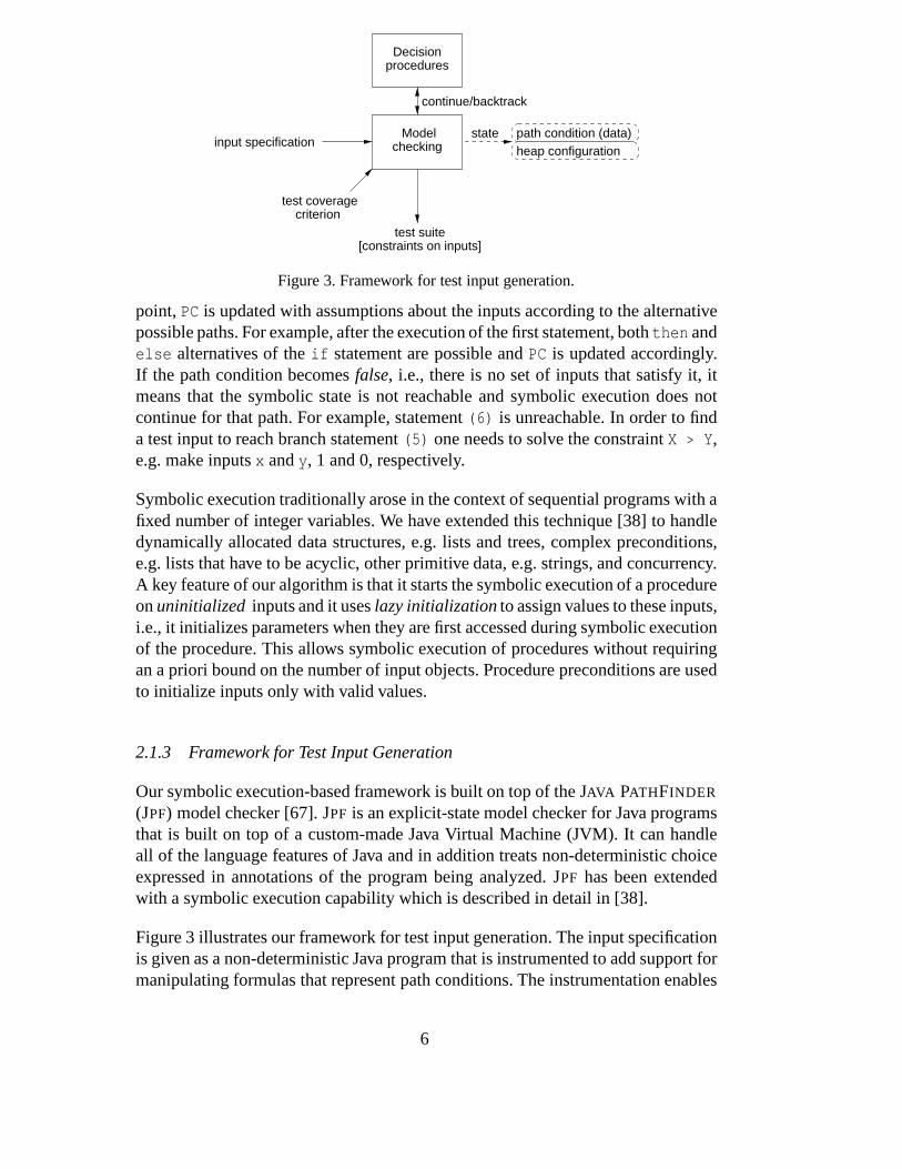
Figure 3. Framework for test input generation.
point, PC is updated with assumptions about the inputs according to the alternativepossible paths. For example, after the execution of the first statement, both then andelse alternatives of the if statement are possible and PC is updated accordingly.If the path condition becomes false, i.e., there is no set of inputs that satisfy it, itmeans that the symbolic state is not reachable and symbolic execution does notcontinue for that path. For example, statement (6) is unreachable. In order to finda test input to reach branch statement (5) one needs to solve the constraint X > Y,e.g. make inputs x and y, 1 and 0, respectively.
Symbolic execution traditionally arose in the context of sequential programs with afixed number of integer variables. We have extended this technique [38] to handledynamically allocated data structures, e.g. lists and trees, complex preconditions,e.g. lists that have to be acyclic, other primitive data, e.g. strings, and concurrency.A key feature of our algorithm is that it starts the symbolic execution of a procedureon uninitialized inputs and it uses lazy initialization to assign values to these inputs,i.e., it initializes parameters when they are first accessed during symbolic executionof the procedure. This allows symbolic execution of procedures without requiringan a priori bound on the number of input objects. Procedure preconditions are usedto initialize inputs only with valid values.
2.1.3 Framework for Test Input Generation
Our symbolic execution-based framework is built on top of the JAVA PATHFINDER
(JPF) model checker [67]. JPF is an explicit-state model checker for Java programsthat is built on top of a custom-made Java Virtual Machine (JVM). It can handleall of the language features of Java and in addition treats non-deterministic choiceexpressed in annotations of the program being analyzed. JPF has been extendedwith a symbolic execution capability which is described in detail in [38].
Figure 3 illustrates our framework for test input generation. The input specificationis given as a non-deterministic Java program that is instrumented to add support formanipulating formulas that represent path conditions. The instrumentation enables
6
JPF to perform symbolic execution. Essentially, the model checker explores thesymbolic state space of the program, for example, the symbolic execution tree inFigure 2. A symbolic state includes information about the heap configuration andthe path condition on integer variables. Whenever a path condition is updated, itis checked for satisfiability using an appropriate decision procedure; currently oursystem uses the Omega library [53] that manipulates linear integer constraints. Ifthe path condition is unsatisfiable, the model checker backtracks. A testing cover-age criterion is encoded in the property the model checker should check for. Thiscauses the model checker to produce a counter-example trace, that represents a paththat satisfies the coverage criterion. The model checker also outputs the input con-straints for this path. Finding a solution to these constraints will allow a valid set oftest data to be produced. Currently a simple approach is used to find these solutions:only the first solution is considered, using an off the shelf constraint solver. In futurework we will refine the solution discovery process to also consider characteristicssuch as boundary cases.
Currently, the model checker is not required to perform state matching, since statematching is, in general, undecidable when states represent path conditions on un-bounded data. Note that symbolic execution performed on programs with loopscan explore infinite execution trees, hence symbolic execution might not termi-nate. Therefore, for systematic state space exploration, limited depth-first search orbreadth-first search is used; our framework also supports various heuristic searchstrategies, for example, based on branch coverage [28] or random search.
2.2 Property Generation
Any verification activity is in essence a consistency check between two artifacts. Inthe framework presented here the check is between the execution of the programon a given input and an automatically generated specification for that given input,consisting of a set of properties about the corresponding execution trace. In othercontexts it may be a check of the consistency between the program and a com-plete specification of the program under all inputs. This redundancy of providinga specification in addition to the program is expensive but necessary. The successof a verification technology partly depends on the cost of producing the specifica-tion. The hypothesis of this work is twofold. First, focusing on the test effort itselfand writing “testing-oriented” properties, rather than a complete formal specifica-tion, may be a cheaper development process. Second, automatically generating thespecification from the input may be easier than writing a specification for all inputs.
More precisely, the artifact produced here is a program that takes an input to theprogram under test and generates a set of properties representing the test oracle.The properties are assertions in temporal logic, which are then checked against theprogram execution using the runtime verification tools described in Section 3.
7

This approach leverages the runtime verification technology to great effect, just astest case generation leverages model checking and symbolic execution. In addition,we anticipate the development of property generation tools specific to a domain orclass of problems. The software under test in our case study is an interpreter for aplan execution language. In this circumstance, the program to generate propertiesuses the decomposition of the plan with respect to the grammar of the plan lan-guage. Like a trivial compiler, the property generator produces test-input-specificproperties as semantic actions corresponding to the parse. Several of NASA’s soft-ware systems have an interpreter structure and it is anticipated that this testingapproach can be applied to several of these as well.
3 Runtime Verification
Runtime verification is divided into two parts: instrumentation and event obser-vation. A monitor receives events from the executing program, emitted by eventgenerators inserted during instrumentation and dispatches them to a collection ofalgorithms, each of which performs a specialized trace analysis. We consider twokinds of such algorithms: the EAGLE temporal logic monitor and three concur-rency analyzers, that can detect deadlock potentials, as well as two kinds of datarace potentials. The concurrency analyzers are currently not yet fully integrated inthe presented testing environment, but are mentioned since they form an interest-ing addition to temporal logic monitoring, experiments have been made and theintension is to integrate them.
Instrumentation can be achieved by code instrumentation or code wrapping. In thecode instrumentation approach, code that generates the event stream is manually orautomatically inserted into source or object code. In the wrapping approach, callsto system library functions within user-defined methods are replaced with calls towrapper functions that generate the event stream and make the system calls. Asan example, Purify [54] uses code instrumentation to check against illegal reads(whether e.g. *p accesses a valid address), and uses wrapping to trace memoryallocations and deallocations.
Our experiments have used manual source code instrumentation as well as manualwrapping. The source code instrumentation approach is used to generate events forthe temporal logic monitoring. The wrapping approach is used to generate eventsfor the deadlock concurrency analysis, where POSIX thread [49] lock and unlockmethods are wrapped and instrumented. In other work, we describe an instrumen-tation package, named JSpy [25], that automatically instruments Java bytecode.However, this could not be applied here as the code to be tested is written in C++.An automated instrumentation is necessary in order to perform data race analysissince all accesses to shared variables need to be monitored.
8

3.1 Temporal Logic Monitoring with EAGLE
Many different languages and logics have been proposed for specifying and an-alyzing properties of program state or event traces, each with characteristics thatmake it more or less suitable for expressing various classes of trace properties; theyrange from stream-based functional, state chart, single-assignment and dataflowlanguages, through pattern-matching languages based on regular (and extended reg-ular) expressions, to a whole host of modal and, in particular, linear-time temporallogics. In Section 5, such languages and logics that have been applied directly toruntime verification are discussed more fully. Since for runtime verification one isinterested in analyzing traces, the framework of linear-time temporal logics (LTL)[52] appeared most appropriate for our own work, but none of the proposed tem-poral logics for runtime verification, of which we were aware, provided the rightcombination of expressivity, naturalness, flexibility, effectiveness and ease of usewe desired. Of course, more often than not, it can be observed that the greaterthe expressivity of the property specification logic, the higher the computationalcost for its analysis. As a consequence this has led us in the past to research effi-cient algorithms for the evaluation of restricted sub-logics, e.g. pure past-time LTL,pure future-time LTL, extended regular expressions, metric temporal logic and soforth. But we were dissatisfied that (i) we had no unifying base logic from whichthese different temporal logics could be built and (ii) we were overly restrictiveon the way properties could be expressed, e.g. forcing pure past, or pure future,etc. Our research thus led us to develop and implement a core, discrete tempo-ral logic, EAGLE, that supports recursively defined formulas, parameterizable byboth logical formulas and data expressions, over a set of four primitive modalitiescorresponding to the “next”, “previous”, “concatenation” and “sequential temporalcomposition” operators. The logic, whilst simple, is expressively rich and enablesusers define their own set of more complex temporal predicates tuned to the par-ticular needs of the run-time verification application. Indeed, in [10] it is shownhow a range of finite-trace monitoring logics, including future-time and past-timetemporal logic, extended regular expressions, real-time and metric temporal logics,interval logics, forms of quantified temporal logics and context free temporal log-ics, can be embedded within EAGLE. However, in order to be truly fit for purpose,the implementation of EAGLE must ensure that “users only pay for what they use”.
3.2 Syntax of EAGLE
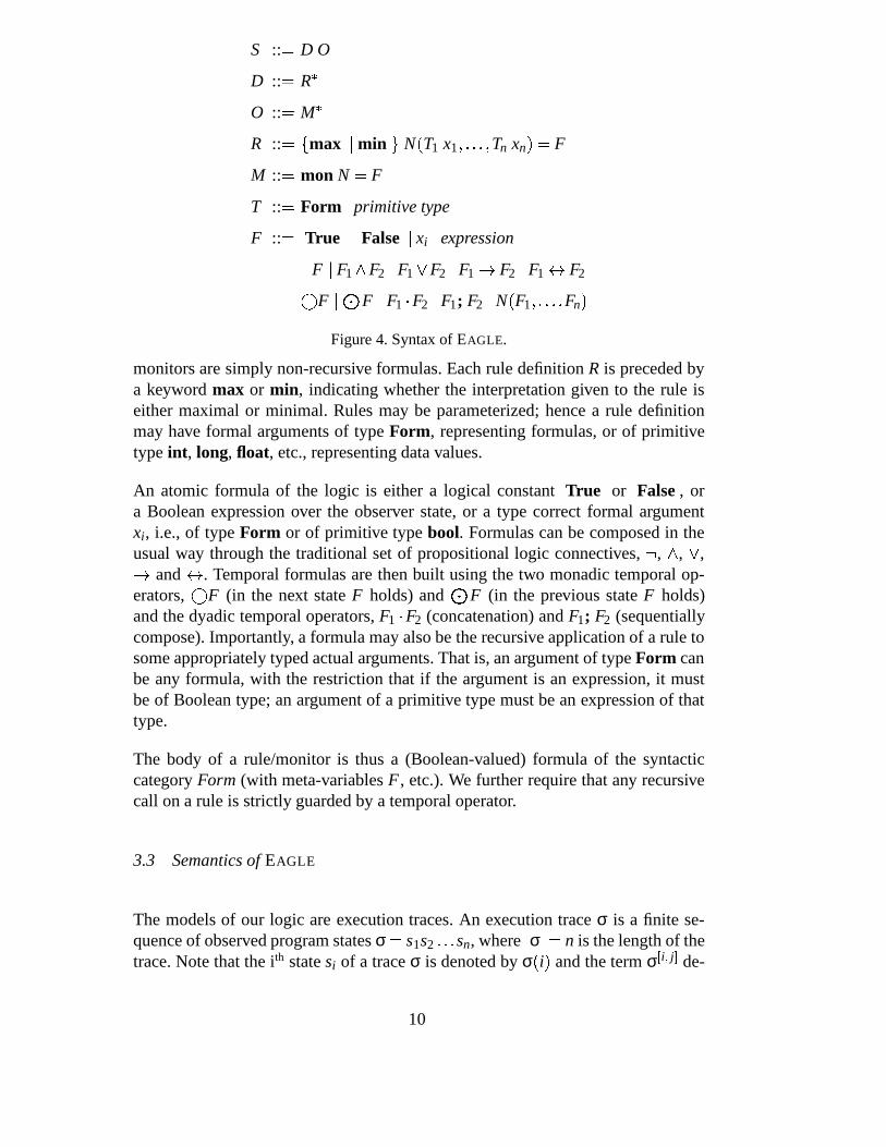
The syntax of EAGLE is shown in Figure 4. A specification S consists of a declara-tion part D and an observer part O. The declaration part, D, comprises zero or morerule definitions R and similarly, the observer part, O, comprises zero or more mon-itor definitions M, which specify the properties that are to be monitored. Both rulesand monitors are named (N), however, rules may be recursively defined, whereas
9
S :: � D O
D :: � R�
O :: � M�
R :: ��� max � min � N � T1 x1 ����� Tn xn � � F
M :: � mon N � F
T :: � Form � primitive type
F :: � True � False � xi � expression
� F � F1 F2 � F1 � F2 � F1 � F2 � F1 � F2�F ��� F � F1 � F2 � F1; F2 � N � F1 ����� Fn �
Figure 4. Syntax of EAGLE.
monitors are simply non-recursive formulas. Each rule definition R is preceded bya keyword max or min, indicating whether the interpretation given to the rule iseither maximal or minimal. Rules may be parameterized; hence a rule definitionmay have formal arguments of type Form, representing formulas, or of primitivetype int, long, float, etc., representing data values.
An atomic formula of the logic is either a logical constant True or False , ora Boolean expression over the observer state, or a type correct formal argumentxi, i.e., of type Form or of primitive type bool. Formulas can be composed in theusual way through the traditional set of propositional logic connectives, � , , � ,� and � . Temporal formulas are then built using the two monadic temporal op-erators,
�F (in the next state F holds) and � F (in the previous state F holds)
and the dyadic temporal operators, F1 � F2 (concatenation) and F1; F2 (sequentiallycompose). Importantly, a formula may also be the recursive application of a rule tosome appropriately typed actual arguments. That is, an argument of type Form canbe any formula, with the restriction that if the argument is an expression, it mustbe of Boolean type; an argument of a primitive type must be an expression of thattype.
The body of a rule/monitor is thus a (Boolean-valued) formula of the syntacticcategory Form (with meta-variables F , etc.). We further require that any recursivecall on a rule is strictly guarded by a temporal operator.
3.3 Semantics of EAGLE
The models of our logic are execution traces. An execution trace σ is a finite se-quence of observed program states σ � s1s2 ��� sn, where �σ � � n is the length of thetrace. Note that the ith state si of a trace σ is denoted by σ � i � and the term σ � i � j � de-
10

σ � i � � D exp iff 1 � i � �σ � and evaluate � exp � � σ � i �� � � true
σ � i � � D True
σ � i �� � D False
σ � i � � D� F iff σ � i �� � D F
σ � i � � D F1 F2 iff σ � i � � D F1 and σ � i � � D F2
σ � i � � D F1 � F2 iff σ � i � � D F1 or σ � i � � D F2
σ � i � � D F1 � F2 iff σ � i � � D F1 implies σ � i � � D F2
σ � i � � D F1 � F2 iff σ � i � � D F1 is equivalent to σ � i � � D F2
σ � i � � D�
F iff i � �σ � and σ � i � 1 � � D F
σ � i � � D � F iff 1 � i and σ � i � 1 � � D F
σ � i � � D F1 � F2 iff � j s.t. i � j � �σ ��� 1 and
σ � 1 � j � 1 � � i � � D F1 and σ � j ���σ � � � 1 � � D F2
σ � i � � D F1; F2 iff � j s.t. i j � �σ ��� 1 and
σ � 1 � j � 1 � � i � � D F1 and σ � j � 1 ���σ � � � 1 � � D F2
σ � i � � D N � F1 ����� Fm � iff
���������� ���������
if 1 � i � �σ � then:
σ � i � � D F � x1 �� F1 ���� � xm �� Fm �where (N � T1 x1 ���� � Tm xm � � F ��� D
otherwise, if i � 0 or i � �σ ��� 1 then:
rule N is defined as max in D
Figure 5. Definition of σ � i � � D F for 0 � i ���σ ��� 1 for some trace σ � s1s2 ����� s �σ � .notes the sub-trace of σ from position i to position j, both positions being included.The semantics of the logic is then defined in terms of a satisfaction relation betweenexecution traces and specifications. That is, given a trace σ and a specification D O,satisfaction is defined as follows:
σ � � D O iff � � mon N � F ��� O � σ � 1 � � D F
A trace satisfies a specification if the trace, observed from position 1 — the index ofthe first observed program state — satisfies each monitored formula. The definitionof the satisfaction relation � � D � � Trace � nat � � Form, for a set of rule definitionsD, is defined inductively over the structure of the formula and is presented in Fig-ure 5. First of all, note that the satisfaction relation � � D is actually defined for theindex range 0 � i � �σ ��� 1 and thus provides a value for a formula before the startof observations and also after the end of observations. This approach was taken to
11
fit with our model of program observation and evaluation of monitoring formulas.The observer only knows the end when it has been passed and no more obser-vation states are forthcoming. It is at that point that a final value for the formulaneeds to be determined. At these boundary points, expressions involving referenceto the observation state (where no state exists) are trivially false. A next-time (resp.previous-time) formula also evaluates false at the point beyond the end (resp. beforethe beginning). A rule, however, has its value at such points determined by whetherit is maximal, in which case it is true, or minimal, in which case it is false. Indeed,there is a correspondence between this evaluation strategy and maximal (minimal)fixed point solutions to the recursive definitions. Thus, for example, referring tothe first three rules defined below in Section 3.4 formula Always � F � will evaluateto true on an empty trace — since Always is defined maximal, whereas formulasEventually � F � and Previously � F � will evaluate to false on an empty trace — asthey are defined as minimal.
The propositional connectives are given their usual interpretation. The next-timeand previous-time temporal operators are as expected. The concatenation and se-quential temporal composition operators are, however, not standard in linear tempo-ral logics, although the sequential temporal composition is often featured in intervaltemporal logics and can also be found in process logics. A concatenation formulaF1 � F2 is true if and only if the trace σ can be split into two sub-traces σ � σ1σ2,such that F1 is true on σ1, observed from the current position i and F2 is true onσ2 from position 1 (relative to σ2). Note that the first formula F1 is not checked onthe second trace σ2 and, similarly, the second formula F2 is not checked on the firsttrace σ1. Also note that either σ1 or σ2 may be an empty sequence. The sequentialtemporal composition differs from concatenation in that the last state of the firstsequence is also the first state of the second sequence. Thus, formula F1; F2 is trueif and only if trace σ can be split into two overlapping sub-traces σ1 and σ2 such
that σ � σ � 1 ���σ1 � � 1 �1 σ2 and σ1 � �σ1 � � � σ2 � 1 � and such that F1 is true on σ1, observed
from the current position i, and F2 is true on σ2 from position 1 (relative to σ2).This operator captures the semantics of sequential composition of finite programs.
Finally, applying a rule within the trace, i.e., positions 1 ��� n, consists of replacingthe call by the right-hand side of its definition, substituting the actual arguments forformal parameters. At the boundaries (0 and n � 1) a rule application evaluates totrue if and only if it is maximal.
3.4 Programming in EAGLE
To illustrate EAGLE we describe the framework for the case study to be presentedin Section 4. Consider a controller for an autonomous mobile robot, referred to asa rover, that executes actions according to a given plan. The goal is to observe thatactions start and terminate in an expected order and within expected time periods.
12

class State extends EagleState {public int kind;// 1=start, 2=end, 3=fail
public String action;public int time;
public boolean start(){return kind == 1;
}
public boolean end(){return kind == 2;
}
public boolean fail(){return kind == 3;
}
public boolean start(String a){return start() && action.equals(a);
}
public boolean end(String a){return end() && action.equals(a);
}
public boolean fail(String a){return fail() && action.equals(a);
}}
Figure 6. The state in which EAGLE Java expressions are evaluated.
Actions can either end successfully, or they can fail. The rover controller is instru-mented to emit events containing an event kind (start, end, or fail), an action name(a string) and a time stamp (an integer) – the number of milliseconds since the startof the application.
event � :: � kind � string � int �
kind � :: � start � end � fail
As events are received by the monitor, they are parsed and stored in a state, whichthe EAGLE formulas can refer to. The state is an object of a user-defined Java classand an example is given in Figure 6. The class defines the state and a set of methodsobserving the state, which can be referred to in EAGLE formulas. To illustrate theuse of formulas as parameters to rules, the following EAGLE fragment defines threerules, Always, Eventually and Previously – corresponding to the usual temporaloperators for “always in the future”, “eventually in the future” and “previously inthe past”.
max Always � Form f � � f � Always � f �min Eventually � Form f � � f � � Eventually � f �min Previously � Form f � � f � � Previously � f �
The following two monitors check that every observed start of the particular action“turn” is matched by a subsequent end of that action and conversely, that every end
13

of the action is preceded by a start of the action.
mon M1 � Always � start � “turn” � � Eventually � end � “turn” ���mon M2 � Always � end � “turn” � � Previously � start � “turn” ���
To illustrate data parameterization, consider the more generic property: “for anyaction, if it starts it must eventually end” and conversely for the past-time case.This is stated as follows.
min EventuallyEnd � String a � � Eventually � end � a ��min PreviouslyStart � String a � � Previously � start � a ��mon M3 � Always � start � � � EventuallyEnd � action ��mon M4 � Always � end � � � PreviouslyStart � action ��
Consider the following properties about real-time behavior, such as the property“when the rover starts a turn, the turn should end within 10 – 30 seconds”. For this,a real-timed version of the Eventually operator is needed. The formulaEventuallyWithin � f � l � u � monitors that f occurs within the relative time boundsl (lower bound) and u (upper bound), measured in seconds. It is defined with thehelp of the auxiliary rule EventuallyAbs, which is an absolute-timed version.
min EventuallyAbs � Form f � int al � int au � �time � au
�� f time � al � �� � f �
EventuallyAbs � f � al � au ���
min EventuallyWithin � Form f � int l � int u � �EventuallyAbs � f � time � � l � 1000 ��� time � � u � 1000 ��
Note that variable time is defined in the state and contains the latest time stamp inmilliseconds since the start of the application. The property “when the rover startsa turn, the turn should end within 10 – 30 seconds” can now be stated as follows:
mon M5 � Always � start � “turn” � � EventuallyWithin � end � “turn” ��� 10 � 30 ��
3.5 Online Evaluation Algorithm
A monitoring algorithm for EAGLE determines whether a trace σ models a mon-itoring specification D O. Our algorithm operates in an online fashion. That is, it
14

is applied sequentially at each state of σ and does not refer back to prior states orforward to future states. This allows the algorithm to be used in online-monitoringcontexts.
Ideally, if a monitoring specification is expressible in a more restricted logic, e.g.LTL, then the EAGLE algorithm should perform about as well as an efficient algo-rithm for the restricted logic. We have for example proved this for LTL [9].
The algorithm employs a function eval � F � s � that examines a state, s, and transformsa monitor F into a monitor F � such that s � σ � 1 � � D F iff s � σ � 2 � � D F � .
The algorithm is, where possible, a direct implementation of the definition of theEAGLE semantics. So for example if D monitors a formula F1 � F2, then (with aslight overloading of the notation)
eval � F1 � F2 � s � � eval � F1 � s � � eval � F2 � s ���Furthermore,
eval � � F � s � � F �However, an online algorithm that examines a trace in temporal order cannot treatthe previous-state operator so easily. Thus the algorithm maintains an auxiliary datastructure used by eval on sub-formulas headed by the � operator, that records theresult of (partially) evaluating the formula in the previous state.
This is illustrated as follows.
min R � int k � � � � y � 1 � � k �mon M � Eventually � R � x ��
This monitor will be true if somewhere in the trace there are two successive statessuch that the value of y in the first state is one less than the value of x in the secondstate. More generally, notice that the combination of parameterizing rules with datavalues and use of the next and previous state operators enable constraints that relatethe values of state variables occurring in different states.
Since eval recursively decomposes the formulas, eventually eval will be called on� � y � 1 � � k � . Note the state variable y refers to the value of y in the previous state,while the formal parameter k is bound to the value of x in the current state. Since theprevious state is unavailable, in the prior step the algorithm must take some action torecord relevant information. Our algorithm pre-evaluates and caches the evaluationof any formula P headed by a previous-state operator, in this case formula y � 1 � �k. However, since the value of k will not be known at that point, the evaluation ispartial. In particular note that the atomic formulas and the underlying expression
15

language (in our case this is Java expressions), must be partially evaluated 5 . Alsonote that since formula P can be arbitrarily complex, in particular another previous-state operator may be nested within, the pre-evaluation is done by a recursive callto eval.
This is basic idea of the algorithm. One subtle point is that the sub-formulas thatmust be pre-evaluated must be identified and properly initialized prior to process-ing the first state. This is done by expanding monitor formulas by unfolding ruledefinitions, while avoiding infinite expansion due to recursive rule definitions. Atthe end of the trace, function value is called yielding a truth value as the final resultof evaluating each monitor over the trace. Function value implements the EAGLE
semantics with respect to boundary conditions regarding the end of the trace.
Function eval yields a formula that may be simplified without altering the correct-ness of the algorithm. Indeed the key to efficient monitoring and provable spacebounds is adequate simplification. In our implementation, formulas are representedin disjunctive normal form where each literal is an instance of negation, the previ-ous, next, concatenation or sequential composition operator or a rule application.Subsumption, i.e., simplifying � a b � � a to a, is essential.
3.6 Complexity of EAGLE
It is evident from the semantics given in Section 3.3 that, in theory, EAGLE is ahighly expressive and powerful language; indeed, given the unrestricted nature ofthe data types and expression language, it is straightforward to see it is Turing-complete. However, what is of interest is the performance of EAGLE on specialcases, i.e., for arbitrary monitors defined over fixed rule sets that implement stan-dard temporal logics. Furthermore one must distinguish complexity due to any datacomputation ascribed to methods defined for state update and predicate evaluationfrom the evaluation of the purely temporal aspects of the logic. An alternative wayof viewing this is to show that our algorithm can meet known optimal bounds forvarious sub-logics embedded within Eagle. To that end, there are some initial com-plexity results that are of interest.
Our first result relates to an embedding of propositional linear-time temporal logic(LTL), over both future and past. In [9], we show that the step evaluation for an ini-tial LTL formula of size m has an upper time complexity bound of O � m422m log2 m �and a space bound of O � m22m logm � , thus showing that the evaluation at any pointis not dependent on the length of the history, i.e., the input seen so far. The result isclose to the lower bound of O � 2 �
m � for monitoring LTL given in [60].
5 A simpler alternative to partial evaluation is to form a closure and do the complete eval-uation when all variables are bound.
16
For metric temporal logic (MTL) where time constants are stated as natural num-bers, embedded in EAGLE, it can be shown that the time and space complexityof monitoring of a formula is 2O � m � where m is the size of the monitored formulaplus the sum of all time constants that appear in the formula. Note that the bound,although exponential, is independent of the length of the trace. The proof for thiscomplexity bound is similar to the proof of the same result in [64].
For real-time logic where time constants are stated as real numbers, embedded inEAGLE, the time and complexity bound, although independent of the length of thetrace, is dependent on the minimum of all time differences between any two eventsin the trace. The bound is given by 2O � mt � δ � where m is the size of the formula, t isthe sum of all time constants appearing in the formula and δ is the minimum timedifference between any two events in the trace monitored.
3.7 A Java Library for Monitoring EAGLE Properties
The EAGLE monitoring engine implements the EAGLE monitoring algorithm as aJava library. The library provides three basic methods, parse, eval and value,that can be called by any client program for the purpose of monitoring. The firstmethod parse takes a file containing a specification involving several monitors(sets of monitored formulas) written in EAGLE and compiles them internally intodata structures representing monitors. After compilation, the client program callsthe method eval iteratively with an observer state. This call internally modifiesthe monitors according to the definition of eval in subsection 3.5. If a monitoredformula becomes false during this modification, it calls a method error which theclient program is expected to implement. Similarly, if a formula becomes true themethod success is called. It is up to the client program to define the observerstate. The client program also modifies the observer state at every event. Once allthe events are consumed the client program calls the method value to check if themonitored formulas are satisfied by the sequence of observer states. If a formula isnot satisfied the method warning implemented by the client is called; otherwise,the method nowarning is invoked.
3.8 Concurrency Analysis
A scheduler may schedule the different threads in a multi-threaded program, suchas the rover controller, in a non-deterministic manner, causing the order in whichthreads access shared objects to differ among different executions on the same in-put. This may lead to different observed execution traces, causing temporal logicspecifications to be violated in some traces while not being violated in others. Con-sequently one cannot infer that a temporal property holds for all traces (that is,holds for the program on some particular input) based on the observation that it
17
holds on some trace. The ideal solution would be a framework for transformingtemporal properties to stronger properties that when checked will be less sensitiveto the non-determinism of traces. Ideally one would like to be able to infer that ifthe property holds on some trace then with high probability it holds on all traces.Or perhaps more importantly: if the property is violated on some trace then it isviolated with high probability on any trace, thereby increasing our chance of de-tecting the problem on a random trace. Although this may appear a very difficultproblem to solve for the general case, it actually can be done for certain propertiesthat are generally desirable for concurrent programs: deadlock freedom and datarace freedom.
Deadlocks can occur when two or more threads acquire locks in a cyclic manner.As an example of such a situation consider two threads T1 and T2 both acquiringlocks A and B. Thread T1 acquires first A and then B before releasing A. Thread T2
acquires B and then A before releasing B. This situation poses a deadlock potentialsince thread T1 can acquire A where upon thread T2 can acquire B, resulting in adeadlocked situation. Potentials for such deadlocks can be detected by identifyingcycles in lock graphs [12]. Another main issue for programmers of multi-threadedapplications is to avoid data races where several threads access a shared object si-multaneously. If all threads utilize the same lock when accessing an object, mutualexclusion is guaranteed, otherwise data races are possible. The Eraser algorithm[57] can detect such data races by maintaining a so-called lock set for each mon-itored variable. Recent work [5] has identified another kind of data races, termedhigh-level data races, that are not detectable by the Eraser algorithm. These racescan occur when sets of fields are accessed incorrectly. Monitors have been devel-oped for analyzing traces for the three above mentioned concurrency problems andautomated instrumentation has been done for Java. For C++, manual instrumenta-tion for deadlock analysis has been done using wrapping as mentioned earlier. Forthe two kinds of data race analysis, automated instrumentation of C++ remains tobe done.
Although the above mentioned concurrency algorithms have been implemented asspecialized programs, one can well imagine using EAGLE for specifying such prop-erties. As an experiment, the deadlock detection algorithm has been encoded in EA-GLE as described in [9], although restricted to the detection of deadlocks betweenpairs of threads. The general algorithm described in [12] can detect deadlock poten-tials between any number of threads. Further work will integrate the concurrencyalgorithms and EAGLE fully.
4 Case Study: A Planetary Rover Controller
The subject of the case study described here is a controller for the K9 planetaryrover, developed at NASA Ames Research Center. A full account of this controller
18
Plan � Node
Node � Block � Task
Block � (block
NodeAttr
:node-list (NodeList))
NodeList � Node NodeList � εTask � (task
NodeAttr
:action Symbol
:duration DurationTime)
NodeAttr � :id Symbol�:start-condition Condition �
�:end-condition Condition �
�:continue-on-failure �
Condition � (time StartTime EndTime)
(block:id plan:continue-on-failure:node-list (
(task:id drive1:start-condition (time +1 +5):end-condition (time +1 +30):action BaseMove1:duration 20
)(task:id drive2:end-condition (time +10 +16):action BaseMove2:duration 20
) ) )
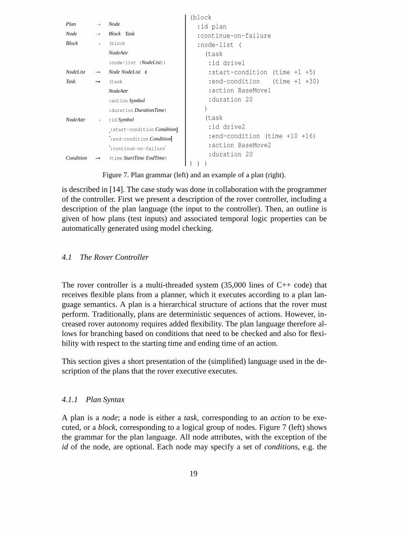
Figure 7. Plan grammar (left) and an example of a plan (right).
is described in [14]. The case study was done in collaboration with the programmerof the controller. First we present a description of the rover controller, including adescription of the plan language (the input to the controller). Then, an outline isgiven of how plans (test inputs) and associated temporal logic properties can beautomatically generated using model checking.
4.1 The Rover Controller
The rover controller is a multi-threaded system (35,000 lines of C++ code) thatreceives flexible plans from a planner, which it executes according to a plan lan-guage semantics. A plan is a hierarchical structure of actions that the rover mustperform. Traditionally, plans are deterministic sequences of actions. However, in-creased rover autonomy requires added flexibility. The plan language therefore al-lows for branching based on conditions that need to be checked and also for flexi-bility with respect to the starting time and ending time of an action.
This section gives a short presentation of the (simplified) language used in the de-scription of the plans that the rover executive executes.
4.1.1 Plan Syntax
A plan is a node; a node is either a task, corresponding to an action to be exe-cuted, or a block, corresponding to a logical group of nodes. Figure 7 (left) showsthe grammar for the plan language. All node attributes, with the exception of theid of the node, are optional. Each node may specify a set of conditions, e.g. the
19

start condition (that must be true at the beginning of node execution) and the endcondition (that must be true at the end of node execution). Each condition includesinformation about a relative or absolute time window, indicating a lower and anupper bound on the time. Flag continue-on-failure indicates what the behavior willbe when an node failure is encountered. Attribute duration specifies the duration ofthe action. Figure 7 (right) shows a plan that has one block with two tasks (drive1and drive2). The time windows here are relative (indicated by the ’+’ signs in theconditions).
4.1.2 Plan Semantics
For every node, execution proceeds through the following steps:
� Wait until the start condition is satisfied; if the current time passes the end of thestart condition, the node times out and this is a node failure.
� The execution of a task proceeds by invoking the corresponding action (e.g. aroutine that interacts with the rover hardware). The action takes the time spec-ified in the :duration attribute when the software is run in simulation mode,with a hardware simulator. The task succeeds or fails, for example depending onwhether the time window is respected. The execution of a block simply proceedsby executing each of the nodes in the node-list in order.
� If time exceeds the end condition, the node fails. On a node failure, when exe-cution returns to the sequence, the value of flag continue-on-failure of the failednode is checked. If true, execution proceeds to the next node in the sequence.Otherwise the node failure is propagated to any enclosing nodes. If the node fail-ure passes out to the top level of the plan, the remainder of the plan is aborted.
4.2 Test Input Generation
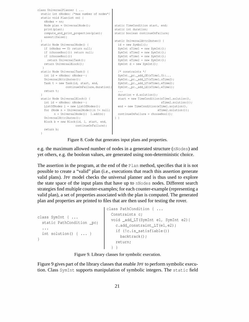
Figure 8 shows part of the Java code, referred to as the universal planner, that isused to generate plans (i.e., test inputs for the executive) and properties (i.e., testoracles, as discussed in the next section). The framework described in Section 2is used to generate test inputs from a specification written as an annotated Javaprogram. Model checking with symbolic execution generates the inputs. The inputplans are specified using non-deterministic choice (choosemethods) over the struc-tures allowed in the grammar presented in Figure 7 and constraints over the integervariables in the input structure (updates to the path condition _pc). For brevity,only a small sample set of constraints is shown here (stating that the time pointsare proper positive values defining intervals and the end time is larger than the starttime of an interval). The actual testing requires solving these constraints in order toinstantiate input plans that can be then executed (method solution). To illustratethe flexibility of our approach, some of the variables are considered concrete inputs,
20
class UniversalPlanner { ...static int nNodes; /*max number of nodes*/static void Plan(int nn) {
nNodes = nn;Node plan = UniversalNode();print(plan);compute_and_print_properties(plan);assert(false);
}static Node UniversalNode() {
if (nNodes == 0) return null;if (chooseBool()) return null;if (chooseBool())return UniversalTask();
return UniversalBlock();}
static Node UniversalTask() {int id = nNodes; nNodes--;UniversalAttributes();Task t = new Task(id, start, end,
continueOnFailure,duration);return t;
}static Node UniversalBlock() {
int id = nNodes; nNodes--;ListOfNodes l = new ListOfNodes();for (Node n = UniversalNode();n != null;
n = UniversalNode()) l.add(n);UniversalAttributes();Block b = new Block(id, l, start, end,
continueOnFailure);return b;
}
static TimeCondition start, end;static int duration;static boolean continueOnFailure;
static UniversalAttributes() {id = new Symbol();SymInt sTime1 = new SymInt();SymInt sTime2 = new SymInt();SymInt eTime1 = new SymInt();SymInt eTime2 = new SymInt();SymInt d = new SymInt();
/* constraints */SymInt._pc._add_GE(sTime1,0);...SymInt._pc._add_LT(sTime1,sTime2);SymInt._pc._add_LT(eTime1,eTime2);SymInt._pc._add_LE(sTime1,eTime1);...duration = d.solution();start = new TimeCondition(sTime1.solution(),
sTime2.solution());end = new TimeCondition(eTime1.solution(),
eTime2.solution());continueOnFailure = chooseBool();
} }
Figure 8. Code that generates input plans and properties.
e.g. the maximum allowed number of nodes in a generated structure (nNodes) andyet others, e.g. the boolean values, are generated using non-deterministic choice.
The assertion in the program, at the end of the Plan method, specifies that it is notpossible to create a “valid” plan (i.e., executions that reach this assertion generatevalid plans). JPF model checks the universal planner and is thus used to explorethe state space of the input plans that have up to nNodes nodes. Different searchstrategies find multiple counter-examples; for each counter-example (representing avalid plan), a set of properties associated with the plan is computed. The generatedplan and properties are printed to files that are then used for testing the rover.
class SymInt { ...static PathCondition _pc;...int solution() { ... }
}
class PathCondition { ...Constraints c;void _add_LT(SymInt e1, SymInt e2){
c.add_constraint_LT(e1,e2);if (!c.is_satisfiable())
backtrack();return;
} }
Figure 9. Library classes for symbolic execution.
Figure 9 gives part of the library classes that enable JPF to perform symbolic execu-tion. Class SymInt supports manipulation of symbolic integers. The static field
21
SymInt._pc stores the (numeric) path condition. Method _add_LT updates the pathcondition with a constraint encoding e1 less-than e2. Method is_satisfiableuses the Omega library to check if the path condition is infeasible (in which case,JPF will backtrack). The solution method first solves the constraints and thenreturns one solution for a symbolic integer.
4.3 Property Generation
For each generated plan, a set of properties formulated in the EAGLE temporal logicis automatically generated, according to the semantics of the planning language.Note that such a set of properties is generated for each plan and monitored duringthe execution of that specific plan. In generating these properties, the followingpredicates are used: start � id � (true immediately after the start of the execution of thenode with the corresponding id), end � id � (true when the execution of the node endssuccessfully) and fail � id � (true when the execution of the node ends with a failure).The code has been instrumented to monitor these predicates and the validity of thegenerated properties is checked on execution traces. As an example, some of thegenerated properties for the plan from Figure 7 (right) are shown in Figure 10.
The set of generated properties does not fully represent the semantics of the plan.As an example, the illustrated properties do not state the fact that drive1 shouldonly start once. A complete specification of the plan semantics would require amore elaborate set of formulas. This would be possible since EAGLE is a veryexpressive logic. However, the current set of properties generated for a plan seemsappropriate to catch many kinds of errors. The effort invested in designing whatproperties to be generated for a particular plan was minimal and likely so due tothe fact that not all the plan semantics is modeled. The properties could be inferredvery directly from the informal plan semantics communicated by the engineer thatprogrammed the system.
4.4 Results
The tool is fully automated after setup and does not require any input from the userto run. The tool generates a set of test cases, each consisting of a plan (input) and aset of properties (expected of the output). A script will execute each test case, firstby running the controller, together with a rover hardware simulator, on the inputplan and then calling EAGLE to verify that the generated execution trace satisfiesthe properties. Due to the automated nature of the process, the developer of the K9rover controller is capable of running it himself. All test results used in the processhave been generated by the developer running the tool.
The automated testing system found (in the first application) a missing feature that
22

� M1 = Eventually(start("plan"))
i.e., the initial node plan should eventually start.
� M2 = Always(start("plan") -> Eventually(end("plan")))
i.e., if plan starts, then it should eventually terminate successfully.
� M3 = Always(start("plan") -> EventuallyWithin(start("drive1"),1,5))
i.e., if plan starts, then drive1 should start within 1 and 5 time units.
� M4 = Always((end("drive2") \/ fail("drive2")) ->Eventually(end("plan")))
i.e., successful or failed termination of drive2 implies successful terminationof the whole plan (due to continue-on-failure flag).
� M5 = Always(start("drive1") ->( EventuallyWithin(end("drive1"),1,30) \/
Eventually(fail("drive1"))))
i.e. if drive1 starts, then it should end successfully within 1 and 30 time units orit should eventually terminate with a failure.
� M6 = Always(fail("drive1") -> ~ Eventually(start("drive2")))
i.e., if drive1 fails, then drive2 should not start.
� M7 = Always(end("drive1") -> Eventually(start("drive2")))
i.e., if drive1 ends successfully, then drive2 should eventually start.
� M8 = Always(start("drive2") -> Eventually(fail("drive2")))
i.e., if drive2 starts, then it should eventually fail (due to the time conditions).
Figure 10. Properties representing partial semantics of plan in Fig. 7.
had been overlooked by the developers: the lower bounds on execution durationwere not enforced. Hence, where a certain generated temporal logic formula pre-dicted failure, the execution in fact wrongly succeeded, and this was detected as aviolation of the temporal property. The error was not corrected immediately afterits detection, and showed up later during actual rover operation in a field test be-fore it was corrected. A preliminary version of the testing environment, not usingautomated test case generation, found a deadlock and a data race. The data race,involving access to a shared variable used to communicate between threads, wassuspected by the developer, but had not been confirmed in code. The trace anal-ysis allowed the developer to see the read/write pattern clearly and redesign thecommunication.
The K9 rover controller, essentially an interpreter, seemed to be very well suitedfor this kind of testing framework. It was in particular simple to determine whattemporal properties should be generated for a plan. This is, however, not as easyin general for other kinds of applications. Another drawback is the fact that only
23
events of the form start, end and fail are monitored. Hence, failures which can onlybe detected by monitoring sub-events between these events cannot be observed.
5 Related Work
5.1 Test Case Generation
In section 2 we have already discussed some of the related work on specification-based testing. Here we link our approach to test input generation tools.
The idea of using constraints to represent inputs dates back at least three decades[37,17,40,55]; the idea has been implemented in various tools including EFFIGY[40], TEGTGEN [42] and INKA [26]. Most of this work has been focused on solv-ing constraints on primitive data, such as integers and booleans.
Some recent frameworks, most notably TestEra [46] and Korat [13,45], do sup-port generation of complex structures. TestEra generates inputs from constraintsgiven in Alloy, a first-order declarative language based on relations. TestEra usesoff-the-shelf SAT solvers to solve constraints. Korat generates inputs from con-straints given as Java predicates. The Korat algorithm has recently been includedin the AsmL Test Generator [22] to enable generation of structures. TestEra andKorat focus on solving structural constraints. They do not directly solve constraintson primitive data as we do in our framework. Instead, they systematically try allprimitive values within given bounds, which may be inefficient.
The first version of AsmLT Test Generator [27] was based on finite-state machines(FSMs): an AsmL [30] specification is transformed into an FSM and differenttraversals of the FSM are used to construct test inputs. Korat adds structure gen-eration to generation based on finite-state machines [27]. AsmLT was successfullyused for detecting faults in a production-quality XPath compiler [63].
Several researchers have investigated the use of model checking for test input gen-eration (see [36] for a good survey). Gargantini and Heitmeyer [23] use a modelchecker to generate tests that violate known properties of a specification given inthe SCR notation. Ammann and Black [4] combine model checking and mutationanalysis to generate test cases from a specification. Rayadurgam et al. use a struc-tural coverage-based approach to generate test cases from specifications given inRSML � e by using a model checker [35]. Hong et al. formulate a theoretical frame-work for using temporal logic to specify data-flow test coverage in [36]. Theseapproaches cannot handle structurally complex inputs.
There are many tools that produce test inputs from a description of tests. QuickCheck
24
[16] is a tool for testing Haskell programs. It requires the tester to write Haskellfunctions that can produce valid test inputs; executions of such functions with dif-ferent random seeds produce different test inputs. Our work differs in that it requiresonly a specification that characterizes valid test inputs and then uses a general-purpose search to generate all valid inputs up to a certain size. DGL [48] andlava [62] generate test inputs from production grammars. They were used mostlyfor random testing, although they can also systematically generate test inputs. How-ever, they cannot easily represent inputs with complex structure, as we do by usingJava as a specification language.
5.2 Runtime verification
The EAGLE logic and its implementation for runtime monitoring has been signif-icantly influenced by earlier work on the executable, trace-generating as well astrace-checking, temporal logic METATEM [8]. In the parallel work [44] a frame-work is described where recursive equations are used to implement a real-timelogic. Although this is a similar approach to the one presented in this paper, EAGLE
goes much further and provides the language of recursive equations to the user,supporting a mixture of future-time and past-time operators and treating real timeas a special case of data values, hence allowing a more general logic.
The most directly case study specific related work is presented in [11], which for thesame rover application describes a framework for generating timed automata fromplans. From the timed automata, monitors are generated that can monitor the planexecution. Since EAGLE can embed timed automata, EAGLE can be seen as a moregeneral framework, that also allows for more partial temporal logic specifications.The main difference in approach is that [11] defines the full semantics of a plan,whereas the here presented temporal logic approach defines a partial semantics.
At a more general level, several runtime verification systems have recently beendeveloped, a collection of which have been presented at a series of runtime ver-ification (RV) workshops [3]. Linear temporal logic (LTL) [52] has been core toseveral of these attempts. The MaC tool [39] supports a past-time interval tempo-ral logic. Real-time is modeled by introducing an explicit state in the specification,containing explicit clock variables, which get updated when new events arrive. Thecommercial tools Temporal Rover and DBRover [18,19], support future-time andpast-time LTL properties, annotated with real-time and data constraints. Alternatingautomata algorithms to monitor LTL properties are proposed in [21] and a special-ized LTL collecting statistics along the execution trace is described in [20]. Variousalgorithms to generate testing automata from temporal logic formulas are discussedin [56,50]. Complexity results for testing a finite trace against temporal formulasexpressed in different temporal logics are investigated in [47]. A technique whereexecution events are stored in an SQL database at runtime is proposed in [43]. These
25
events are then analyzed by queries derived from interval logic temporal formulasafter the program terminates. The PET tool [29] uses a future-time temporal logicformula to guide the execution of a program for debugging purposes. The model-based specification language AsmL is being used for runtime verification [7], aswell as for test case generation (see Section 5.1). AsmL is a very comprehensivegeneral-purpose specification language for abstractly specifying computation steps.It does not directly support temporal logic.
Our own related work includes the development of several algorithms for moni-toring with temporal logic, such as generating dynamic programming algorithmsfor past-time logic [34], using a rewriting system for monitoring future-time logic[33,32], or generating Büchi automata inspired algorithms adapted to finite-traceLTL [24]. A logic based on extended regular expressions is described in [59].Java MultiPathExplorer [61] is a tool which checks a past-time LTL safety for-mula against a partial order extracted online from an execution trace. POTA [58]is another partial-order trace analyzer system. Java-MoP [15] is a generic logicmonitoring tool encouraging “monitoring-oriented programming”. JNuke [6] is aframework that combines runtime verification and model checking. It is written inC, achieving scalability through high performance and low memory usage.
6 Conclusions and Future Work
A framework for testing based on automated test case generation and runtime ver-ification has been presented. This paper proposed and demonstrated the use ofmodel checking and symbolic execution for test case generation using the JAVA
PATHFINDER tool, and the use of temporal logic monitoring in EAGLE during theexecution of the test cases. The framework requires construction of a test input andproperty generator for the application. From that, a large test suite can be automat-ically generated, executed and verified to be in conformity with the properties. Foreach input is generated a set of EAGLE properties that must hold when the pro-gram under test is executed on that input. The program is instrumented to emit anexecution log of events. An observer checks that the event log satisfies the set ofproperties.
We take the position that writing test oracles as temporal logic formulas is bothnatural and leverages algorithms that efficiently check if execution on a test inputconforms to the properties. Due to EAGLE’s expressive power, properties can fur-thermore be stated in combinations of different sub-logics and notations, such asfor example temporal logic, regular expressions and state machines. While propertydefinition in general often is difficult, an effective approach for some domains maybe to write a property generator, rather than a universal set of properties that are in-dependent of the test inputs. Note also that the properties need not completely char-acterize correct execution. Instead, a user can choose among a spectrum of weak
26

but easily generated properties to strong properties that may require constructionof complex formulas.
In the near future, we will be exploring how to improve the quality of the generatedtest suite by altering the search strategy of the model checker and by improvingthe symbolic execution technology. We will also investigate improvements to theEAGLE logic and its engine. Experiments will be made combining different speci-fication paradigms, such as temporal logic, regular expressions and state machines,all currently expressible in EAGLE within a single framework. Furthermore, an at-tempt will be made to integrate the concurrency analysis algorithms for deadlockand data race analysis fully into EAGLE. We are continuing the work on instru-mentation of Java bytecode and will extend this work to C and C++. Our researchgroup has done fundamental research in other areas, such as software model check-ing (model checking the application itself and not just the input domain) and staticanalysis. In general, our ultimate goal is to combine the different technologies intoa single coherent framework.
References
[1] AGEDIS - model based test generation tools. http://www.agedis.de.
[2] The test sequence generator TGV. http://www-verimag.imag.fr/~async/TGV.
[3] 1st, 2nd, 3rd and 4th Workshops on Runtime Verification (RV’01 - RV’04), volume55(2), 70(4), 89(2), (RV’04 to be published) of ENTCS. Elsevier Science: 2001, 2002,2003, 2004.
[4] P. Ammann and P. Black. A Specification-Based Coverage Metric to Evaluate TestSets. In Proceedings of the 4th IEEE International Symposium on High AssuranceSystems and Engineering, pages 239–248, November 1999.
[5] C. Artho, K. Havelund, and A. Biere. High-level Data Races. In VVEIS’03: TheFirst International Workshop on Verification and Validation of Enterprise InformationSystems, France, April 2003.
[6] C. Artho, V. Schuppan, A. Biere, P. Eugster, M. Baur, and B. Zweimüller. JNuke:Efficient Dynamic Analysis for Java. In Proc. of CAV’04: Computer Aided Verification– to appear, Lecture Notes in Computer Science. Springer-Verlag, 2004.
[7] M. Barnett and W. Schulte. Contracts, Components, and their Runtime Verification.Technical Report MSR-TR-2002-38, Microsoft Research, April 2002. Download:http://research.microsoft.com/fse.
[8] H. Barringer, M. Fisher, D. Gabbay, G. Gough, and R. Owens. METATEM: AnIntroduction. Formal Aspects of Computing, 7(5):533–549, 1995.
[9] H. Barringer, A. Goldberg, K. Havelund, and K. Sen. Program Monitoring with LTLin EAGLE. In Proceedings of Workshop on Parallel and Distributed Systems: Testingand Debugging (PADTAD’04) – to appear, Santa Fe, New Mexico, USA, April 2004.
27

[10] H. Barringer, A. Goldberg, K. Havelund, and K. Sen. Rule-Based RuntimeVerification. In B. Steffen and G. Levi, editors, Proceedings of Fifth InternationalConference on Verification, Model Checking and Abstract Interpretation, volume 2937of Lecture Notes in Computer Science, pages 44–57. Springer, January 2004.
[11] S. Bensalem, M. Bozga, M. Krichen, and S. Tripakis. Testing Conformance of Real-Time Software by Automatic Generation of Observers. In Proc. of RV’04: FourthInternational Workshop on Runtime Verification, Electronic Notes in TheoreticalComputer Science, Barcelona, Spain, 2004. Elsevier Science.
[12] S. Bensalem and K. Havelund. Deadlock Analysis of Multi-Threaded Java Programs.Kestrel Technology, NASA Ames Research Center, California, October 2002.
[13] C. Boyapati, S. Khurshid, and D. Marinov. Korat: Automated Testing Based onJava Predicates. In Proc. International Symposium on Software Testing and Analysis(ISSTA), pages 123–133, July 2002.
[14] G. Brat, D. Giannakopoulou, A. Goldberg, K. Havelund, M. Lowry, C. Pasareanu,A. Venet, and W. Visser. Experimental Evaluation of Verification and ValidationTools on Martian Rover Software. In SEI Software Model Checking Workshop, 2003.Extended version to appear in the journal Formal Methods in System Design.
[15] F. Chen and G. Rosu. Towards Monitoring-Oriented Programming: A ParadigmCombining Specification and Implementation. In Proc. of RV’03: the ThirdInternational Workshop on Runtime Verification, volume 89(2) of Electronic Notesin Theoretical Computer Science, Boulder, USA, 2003. Elsevier Science.
[16] K. Claessen and J. Hughes. Testing Monadic Code with QuickCheck. In Proc. ACMSIGPLAN workshop on Haskell, pages 65–77, 2002.
[17] L. A. Clarke. A System to Generate Test Data and Symbolically Execute Programs.IEEE Transactions on Software Engineering, SE-2:215–222, September 1976.
[18] D. Drusinsky. The Temporal Rover and the ATG Rover. In Proc. of SPIN’00: SPINModel Checking and Software Verification, volume 1885 of Lecture Notes in ComputerScience, pages 323–330, Stanford, California, USA, 2000. Springer.
[19] D. Drusinsky. Monitoring Temporal Rules Combined with Time Series. In Proc. ofCAV’03: Computer Aided Verification, volume 2725 of Lecture Notes in ComputerScience, pages 114–118, Boulder, USA, 2003. Springer-Verlag.
[20] B. Finkbeiner, S. Sankaranarayanan, and H. Sipma. Collecting Statistics over RuntimeExecutions. In Proc. of RV’02: The Second International Workshop on RuntimeVerification, volume 70(4) of Electronic Notes in Theoretical Computer Science, Paris,France, 2002. Elsevier Science.
[21] B. Finkbeiner and H. Sipma. Checking Finite Traces using Alternating Automata.Formal Methods in System Design, 24(2):101–128, March 2004.
[22] Foundations of Software Engineering, Microsoft Research. The AsmL test generatortool. http://research.microsoft.com/fse/asml/doc/AsmLTester.html.
28

[23] A. Gargantini and C. Heitmeyer. Using Model Checking to Generate Tests fromRequirements Specifications. In Proceedings of the 7th European engineeringconference held jointly with the 7th ACM SIGSOFT international symposium onFoundations of software engineering, pages 146–162. Springer-Verlag, 1999.
[24] D. Giannakopoulou and K. Havelund. Automata-Based Verification of TemporalProperties on Running Programs. In Proc. of ASE’01: International Conferenceon Automated Software Engineering, pages 412–416. Institute of Electrical andElectronics Engineers, Coronado Island, California, 2001.
[25] A. Goldberg and K. Havelund. Instrumentation of Java Bytecode for RuntimeAnalysis. In Proc. Formal Techniques for Java-like Programs, volume 408 ofTechnical Reports from ETH Zurich, Switzerland, 2003. ETH Zurich.
[26] A. Gotlieb, B. Botella, and M. Rueher. Automatic Test Data Generation usingConstraint Solving Techniques. In Proc. International Symposium on Software Testingand Analysis (ISSTA), pages 53–62, Clearwater Beach, FL, March 1998.
[27] W. Grieskamp, Y. Gurevich, W. Schulte, and M. Veanes. Generating Finite StateMachines from Abstract State Machines. In Proc. International Symposium onSoftware Testing and Analysis (ISSTA), pages 112–122, July 2002.
[28] A. Groce and W. Visser. Model Checking Java Programs using Structural Heuristics.In Proceedings of the 2002 International Symposium on Software Testing and Analysis(ISSTA), pages 12 – 21. ACM Press, July 2002.
[29] E. Gunter and D. Peled. Tracing the Executions of Concurrent Programs. In Proc.of RV’02: Second International Workshop on Runtime Verification, volume 70(4)of Electronic Notes in Theoretical Computer Science, Copenhagen, Denmark, 2002.Elsevier Science.
[30] Y. Gurevich. Evolving Algebras 1993: Lipari Guide. In Specification and ValidationMethods, pages 9–36. Oxford University Press, 1995.
[31] A. Hartman. Model Based Test Generation Tools.http://www.agedis.de/documents/ModelBasedTestGenerationTools_cs.pdf.
[32] K. Havelund and G. Rosu. Monitoring Programs using Rewriting. In Proceedingsof the International Conference on Automated Software Engineering (ASE’01), pages135–143. IEEE CS Press, Coronado Island, California, 2001. Extended version toappear in the journal Automated Sofware Engineering.
[33] K. Havelund and G. Rosu. An Overview of the Runtime Verification Tool JavaPathExplorer. Formal Methods in System Design, 24(2):189–215, March 2004.
[34] K. Havelund and G. Rosu. Synthesizing Monitors for Safety Properties. In Tools andAlgorithms for Construction and Analysis of Systems (TACAS’02), volume 2280 ofLNCS, pages 342–356. Springer, 2002. Extended version to appear in the InternationalJournal on Software Tools for Technology Transfer.
[35] M. P. E. Heimdahl, S. Rayadurgam, W. Visser, D. George, and J. Gao. Auto-Generating Test Sequences using Model Checkers: A Case Study. In Proc. 3rd
29
International Workshop on Formal Approaches to Testing of Software (FATES),volume 2931 of Lecture Notes in Computer Science, pages 42–59, Montreal, Canada,October 2003. Springer.
[36] H. Seok Hong, I. Lee, O. Sokolsky, and H. Ural. A Temporal Logic Based Theoryof Test Coverage and Generation. In Proc. 8th International Conference on Toolsand Algorithms for Construction and Analysis of Systems (TACAS), volume 2280 ofLecture Notes in Computer Science, pages 327–341, Grenoble, France, April 2002.Springer.
[37] J. C. Huang. An Approach to Program Testing. ACM Computing Surveys, 7(3), 1975.
[38] S. Khurshid, C. Pasareanu, and W. Visser. Generalized Symbolic Execution for ModelChecking and Testing. In Proceedings of TACAS’03: Tools and Algorithms for theConstruction and Analysis of Systems, volume 2619 of LNCS, Warsaw, Poland, April2003.
[39] M. Kim, M. Viswanathan, S. Kannan, I. Lee, and O. Sokolsky. Java-MaC: a Run-timeAssurance Tool for Java. Formal Methods in System Design, 24(2):129–156, March2004.
[40] J. C. King. Symbolic Execution and Program Testing. Communications of the ACM,19(7):385–394, 1976.
[41] B. Korel. Automated Software Test Data Generation. IEEE Transaction on SoftwareEngineering, 16(8):870–879, August 1990.
[42] B. Korel. Automated Test Data Generation for Programs with Procedures. In Proc.International Symposium on Software Testing and Analysis (ISSTA), pages 209–215,San Diego, CA, 1996.
[43] D. Kortenkamp, R. Simmons, T. Milam, and J. Fernandez. A Suite of Tools forDebugging Distributed Autonomous Systems. Formal Methods in System Design,24(2):157–188, March 2004.
[44] K. Jelling Kristoffersen, C. Pedersen, and H. R. Andersen. Runtime Verification ofTimed LTL using Disjunctive Normalized Equation Systems. In Proc. of RV’03: ThirdInternational Workshop on Runtime Verification, volume 89(2) of Electronic Notes inTheoretical Computer Science, Boulder, USA, 2003. Elsevier Science.
[45] D. Marinov. Testing Using a Solver for Imperative Constraints. PhD thesis, ComputerScience and Artificial Intelligence Laboratory, Massachusetts Institute of Technology,2004. (to appear).
[46] D. Marinov and S. Khurshid. TestEra: A Novel Framework for Automated Testing ofJava Programs. In Proc. 16th IEEE International Conference on Automated SoftwareEngineering (ASE), pages 22–34, San Diego, CA, November 2001.
[47] N. Markey and P. Schnoebelen. Model Checking a Path (Preliminary Report). In Proc.of CONCUR’03: International Conference on Concurrency Theory, volume 2761 ofLecture Notes in Computer Science, pages 251–265, Marseille, France, August 2003.Springer.
30

[48] P. M. Maurer. Generating Test Data with Enhanced Context-Free Grammars. IEEESoftware, 7(4):50–55, July 1990.
[49] B. Nichols, D. Buttlar, and J. P. Farrell. Pthreads Programming. O’Reilly, 1998.
[50] T. O’Malley, D. Richardson, and L. Dillon. Efficient Specification-Based Oracles forCritical Systems. In Proc. of the California Software Symposium, 1996.
[51] Parasoft. http://www.parasoft.com.
[52] A. Pnueli. The Temporal Logic of Programs. In Proceedings of the 18th IEEESymposium on Foundations of Computer Science, pages 46–77, 1977.
[53] W. Pugh. A Practical Algorithm for Exact Array Dependence Analysis.Communications of the ACM, 35(8):102 – 114, August 1992.
[54] Purify: Fast Detection of Memory Leaks and Access Errors. January 1992.
[55] C. V. Ramamoorthy, Siu-Bun F. Ho, and W. T. Chen. On the Automated Generation ofProgram Test Data. IEEE Transactions on Software Engineering, 2(4):293–300, 1976.
[56] D. J. Richardson, S. L. Aha, and T. O. O’Malley. Specification-Based Test Oraclesfor Reactive Systems. In Proc. of ICSE’92: International Conference on SoftwareEngineering, pages 105–118, Melbourne, Australia, 1992.
[57] S. Savage, M. Burrows, G. Nelson, P. Sobalvarro, and T. Anderson. Eraser: A DynamicData Race Detector for Multithreaded Programs. ACM Transactions on ComputerSystems, 15(4):391–411, November 1997.
[58] A. Sen and V. K. Garg. Partial Order Trace Analyzer (POTA) for Distributed Programs.In Proc. of RV’03: the Third International Workshop on Runtime Verification, volume89(2) of Electronic Notes in Theoretical Computer Science, Boulder, USA, 2003.Elsevier Science.
[59] K. Sen and G. Rosu. Generating Optimal Monitors for Extended Regular Expressions.In Proc. of RV’03: Third International Workshop on Runtime Verification, volume89(2) of Electronic Notes in Theoretical Computer Science, Boulder, USA, 2003.Elsevier Science.
[60] K. Sen, G. Rosu, and G. Agha. Generating Optimal Linear Temporal Logic Monitorsby Coinduction. In V.A. Saraswat, editor, Proceedings of 8th Asian Computing ScienceConference (ASIAN’03), volume 2896 of Lecture Notes in Computer Science, pages260–275, December 2003.
[61] K. Sen, G. Rosu, and G. Agha. Runtime Safety Analysis of Multithreaded Programs.In Proc. of ESEC/FSE’03: European Software Engineering Conference and ACMSIGSOFT International Symposium on the Foundations of Software Engineering,pages 337 – 346. ACM, Helsinki, Finland, September 2003.
[62] E. G. Sirer and B. N. Bershad. Using Production Grammars in Software Testing. InProc. 2nd conference on Domain-specific languages, pages 1–13, 1999.
[63] K. Stobie. Advanced Modeling, Model Based Test Generation, and Abstract statemachine Language AsmL. http://www.sasqag.org/pastmeetings/asml.ppt, 2003.
31

[64] P. Thati and G. Rosu. Monitoring Algorithms for Metric Temporal Logic. In Proc.of RV’04: Fourth International Workshop on Runtime Verification, Electronic Notes inTheoretical Computer Science, Barcelona, Spain, 2004. Elsevier Science. To appear.
[65] N. Tracey, J. Clark, and K. Mander. The Way Forward for Unifying Dynamic Test-Case Generation: The Optimisation-Based Approach. In International Workshop onDependable Computing and Its Applications (DCIA), pages 169–180. IFIP, January1998.
[66] T-VEC. http://www.t-vec.com.
[67] W. Visser, K. Havelund, G. Brat, S.-J. Park, and F. Lerda. Model Checking Programs.Automated Software Engineering Journal, 10(2):203–232, April 2003.
32