![Phase stabilization of mode-locked lasersjunye/yelabsOLD/pubs/science...mode-locked Ti:sapphire lasers [9, 10]. It is also possible to use an auxiliary CW laser [19–21]; however,](https://static.fdocuments.in/doc/165x107/611c631d3eb22307be7a4ce5/phase-stabilization-of-mode-locked-lasers-junyeyelabsoldpubsscience-mode-locked.jpg)
Combined cw single-frequency ring dye/Ti:sapphire laser
5
Abstract. A new combined cw single-frequency dye/Ti : sap- phire laser with a ring resonator located in the horizontal plane and improved radiation frequency stability is developed. The short-term radiation linewidth does not exceed 10 kHz for the Ti : sapphire laser and is smaller than 100 kHz for the dye laser. The drift velocity of the emission line does not exceed 25 MHz h 1 . The scheme and design of the developed laser are presented which allow convenient switching of the laser between its solid-state and dye conØgurations. Keywords: continuous-wave single-frequency ring laser, dye laser, Ti : sapphire laser, laser radiation frequency stabilisation. 1. Introduction Dye and Ti : sapphire lasers can be tuned in broad spectral ranges which are among the broadest ranges inherent in tunable lasers. The tuning ranges of these lasers are over- lapped in the region between 700 and 800 nm. However, a Ti : sapphire laser is, as a rule, preferable for operating in the range above 700 nm as more efØcient and simple for this wavelength range, while dye lasers are traditionally used in the region below 700 nm. The idea of the develop- ment of a combined tunable laser based on a Ti : sapphire laser and a dye laser is quite reasonable because such a laser can be tuned in a very broad spectral range from the visible to near-IR region. The development of a combined tunable laser is espe- cially expedient in the case of cw Ti : sapphire and dye lasers in which similar selecting elements and optical schemes are used (the active medium is located between two short-focus spherical mirrors, etc.). Another important argument in favour of the creation of a combined laser is that a Ti : sapphire laser and many dye lasers can be pumped by the same lasers. Until now, only one combined cw single-frequency Ti : sapphire/dye ring laser was available (model 899, Coherent). The resonator of this laser was Ørst used in a dye laser [1] and then in combined liquid º solid-state laser [2]. The main component of this laser design is a massive invar rod on which holders for all optical elements forming the vertical resonator of the laser are Øxed. Most of the elements are located near the supporting invar rod; however, some of them are remote from the rod, which, of course, impairs the passive stability of the resonator. The emission linewidth of this laser in the frequency stabilisation regime is approximately 500 kHz and the drift velocity of the emission line does not exceed 50 MHz h 1 [3]. At the time of the development of this laser, more than two decades ago, these parameters were considered ‘top-level’; however, at present even some commercial Ti : sapphire lasers emit lines of width smaller than 100 kHz [4, 5]. The aim of this work was the development of a com- bined cw single-mode Ti : sapphire/dye ring laser with improved emission parameters of lasers of both types. In this paper, we present the results of detailed experimental tests of this laser. 2. The laser design The resonator of a combined laser is based on the scheme of a Ti : sapphire laser proposed in [6]. The speciØc feature and advantage of the ring resonator of this laser is the absence of the ultraØne quartz birefringent plate, which is commonly used together with a Faraday element in ring lasers [2, 4] to generate a single travelling wave. Optical rotation in the resonator described in [6] is performed by using a mirror located outside the resonator plane. In addition, the laser design makes it possible to obtain generation in a linear resonator, in particular, with all selecting elements and even a Faraday rotator, which is important for the preliminary optimisation of the adjust- ment of these elements. The idea of realisation of a dye laser based on this scheme is to place a dye solution jet in the short arm of the resonator (see the resonator scheme in Fig. 1). A Ti : sap- phire crystal is removed from the intermediate (in length) arm of the resonator, spherical mirror M1 of the Ti : sap- phire laser resonator is replaced by a Œat mirror (mirror M3 of the dye laser resonator) and plane mirror M3 of the Ti : sapphire laser resonator is replaced by a spherical mirror (mirror M1 of the dye laser resonator). In addition, spherical mirror M2 (R 100 mm for the Ti : sapphire laser) is replaced by a spherical mirror with R 75 mm and the pump beam is directed to the dye jet with auxiliary spherical mirror PM4. The positions of most optic holders in the combined laser do not change upon laser switching from one conØguration to another (part I in Fig. 1). Thus, the resonator is switched from the dye laser conØguration to the Ti : sapphire laser conØguration and S.M. Kobtsev, V.I. Baraulya Novosibirsk State University, ul. Pirogova 2, 630090 Novosibirsk, Russia; e-mail: [email protected]; V.M. Lunin Tekhnoscan Joint-Stock Company, ul. Sirenevaya 37, k. 141, 630058 Novosibirsk, Russia; e-mail: [email protected] Received 2 August 2006 Kvantovaya Elektronika 36 (12) 1148 º 1152 (2006) Translated by M.N. Sapozhnikov PACS numbers: 42.55.Mv; 42.55.Rz; 42.60. ^ v LASERS DOI:10.1070/QE2006v036n12ABEH013369 Combined cw single-frequency ring dye/Ti : sapphire laser S.M. Kobtsev, V.I. Baraulya, V.M. Lunin 234/181 º VOLO º 2/ii-07 º SVERKA º 5 ÒÑ˛ÑÔ ˝ÑˇÒ. å 3 Quantum Electronics 36 (12) 1148 º 1152 (2006) ß2006 Kvantovaya Elektronika and Turpion Ltd
-
Upload
truongmien -
Category
Documents
-
view
216 -
download
1
Transcript of Combined cw single-frequency ring dye/Ti:sapphire laser
Abstract. A new combined cw single-frequency dye/Ti : sap-phire laser with a ring resonator located in the horizontalplane and improved radiation frequency stability is developed.The short-term radiation linewidth does not exceed 10 kHzfor the Ti : sapphire laser and is smaller than 100 kHz for thedye laser. The drift velocity of the emission line does notexceed 25 MHz hÿ1. The scheme and design of the developedlaser are presented which allow convenient switching of thelaser between its solid-state and dye conégurations.
Keywords: continuous-wave single-frequency ring laser, dye laser,Ti : sapphire laser, laser radiation frequency stabilisation.
1. Introduction
Dye and Ti : sapphire lasers can be tuned in broad spectralranges which are among the broadest ranges inherent intunable lasers. The tuning ranges of these lasers are over-lapped in the region between 700 and 800 nm. However, aTi : sapphire laser is, as a rule, preferable for operating inthe range above 700 nm as more efécient and simple forthis wavelength range, while dye lasers are traditionallyused in the region below 700 nm. The idea of the develop-ment of a combined tunable laser based on a Ti : sapphirelaser and a dye laser is quite reasonable because such a lasercan be tuned in a very broad spectral range from the visibleto near-IR region.
The development of a combined tunable laser is espe-cially expedient in the case of cw Ti : sapphire and dye lasersin which similar selecting elements and optical schemes areused (the active medium is located between two short-focusspherical mirrors, etc.). Another important argument infavour of the creation of a combined laser is that aTi : sapphire laser and many dye lasers can be pumpedby the same lasers.
Until now, only one combined cw single-frequencyTi : sapphire/dye ring laser was available (model 899,Coherent). The resonator of this laser was érst used in adye laser [1] and then in combined liquid ë solid-state laser[2]. The main component of this laser design is a massive
invar rod on which holders for all optical elements formingthe vertical resonator of the laser are éxed. Most of theelements are located near the supporting invar rod; however,some of them are remote from the rod, which, of course,impairs the passive stability of the resonator. The emissionlinewidth of this laser in the frequency stabilisation regime isapproximately 500 kHz and the drift velocity of theemission line does not exceed 50 MHz hÿ1 [3]. At thetime of the development of this laser, more than twodecades ago, these parameters were considered `top-level';however, at present even some commercial Ti : sapphirelasers emit lines of width smaller than 100 kHz [4, 5].
The aim of this work was the development of a com-bined cw single-mode Ti : sapphire/dye ring laser withimproved emission parameters of lasers of both types. Inthis paper, we present the results of detailed experimentaltests of this laser.
2. The laser design
The resonator of a combined laser is based on the schemeof a Ti : sapphire laser proposed in [6]. The speciéc featureand advantage of the ring resonator of this laser is theabsence of the ultraéne quartz birefringent plate, which iscommonly used together with a Faraday element in ringlasers [2, 4] to generate a single travelling wave. Opticalrotation in the resonator described in [6] is performed byusing a mirror located outside the resonator plane. Inaddition, the laser design makes it possible to obtaingeneration in a linear resonator, in particular, with allselecting elements and even a Faraday rotator, which isimportant for the preliminary optimisation of the adjust-ment of these elements.
The idea of realisation of a dye laser based on thisscheme is to place a dye solution jet in the short arm of theresonator (see the resonator scheme in Fig. 1). A Ti : sap-phire crystal is removed from the intermediate (in length)arm of the resonator, spherical mirror M1 of the Ti : sap-phire laser resonator is replaced by a êat mirror (mirror M3of the dye laser resonator) and plane mirror M3 of theTi : sapphire laser resonator is replaced by a spherical mirror(mirror M1 of the dye laser resonator). In addition,spherical mirror M2 (R � 100 mm for the Ti : sapphirelaser) is replaced by a spherical mirror with R � 75 mmand the pump beam is directed to the dye jet with auxiliaryspherical mirror PM4. The positions of most optic holdersin the combined laser do not change upon laser switchingfrom one conéguration to another (part I in Fig. 1).
Thus, the resonator is switched from the dye laserconéguration to the Ti : sapphire laser conéguration and
S.M. Kobtsev, V.I. Baraulya Novosibirsk State University, ul. Pirogova2, 630090 Novosibirsk, Russia; e-mail: [email protected];V.M. Lunin Tekhnoscan Joint-Stock Company, ul. Sirenevaya 37, k.141, 630058 Novosibirsk, Russia; e-mail: [email protected]
Received 2 August 2006Kvantovaya Elektronika 36 (12) 1148 ë 1152 (2006)Translated by M.N. Sapozhnikov
PACSnumbers:42.55.Mv; 42.55.Rz; 42.60. ^ vLASERS
DOI:10.1070/QE2006v036n12ABEH013369
Combined cw single-frequency ring dye/Ti : sapphire laser
S.M. Kobtsev, V.I. Baraulya, V.M. Lunin
234/181 ëVOLO ë 2/ii-07 ë SVERKA ë 5 ÒÑÎÑÔ ÍÑÏÒ. å 3Quantum Electronics 36 (12) 1148 ë 1152 (2006) ß2006 Kvantovaya Elektronika and Turpion Ltd
vice versa by replacing resonator mirrors and Faradayrotator and interchanging several optic holders. A birefrin-gent élter and a thick etalon can be used in bothconégurations of the combined laser. This scheme is alsoconvenient because the laser can operate in both conégura-tions with the ring and linear resonators. The possibility oflasing in both conégurations with the linear resonator(without mirror M5) considerably simpliéers the prelimi-nary optimisation of the adjustment of the resonator andselectors. The electronic control systems and frequencystabilisation systems for both lasers are identical.
3. Vertical direction of the dye jet
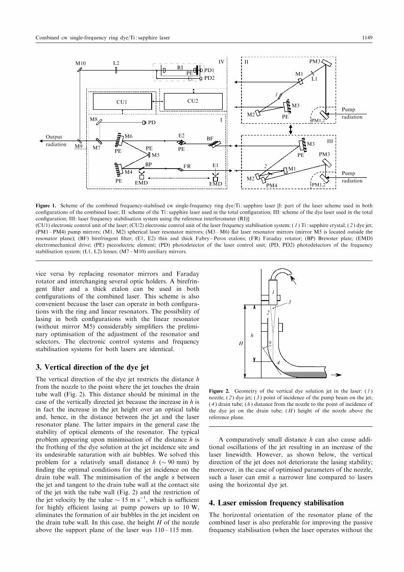
The vertical direction of the dye jet restricts the distance hfrom the nozzle to the point where the jet touches the draintube wall (Fig. 2). This distance should be minimal in thecase of the vertically directed jet because the increase in h isin fact the increase in the jet height over an optical tableand, hence, in the distance between the jet and the laserresonator plane. The latter impairs in the general case thestability of optical elements of the resonator. The typicalproblem appearing upon minimisation of the distance h isthe frothing of the dye solution at the jet incidence site andits undesirable saturation with air bubbles. We solved thisproblem for a relatively small distance h (� 90 mm) byénding the optimal conditions for the jet incidence on thedrain tube wall. The minimisation of the angle a betweenthe jet and tangent to the drain tube wall at the contact siteof the jet with the tube wall (Fig. 2) and the restriction ofthe jet velocity by the value � 15 m sÿ1, which is sufécientfor highly efécient lasing at pump powers up to 10 W,eliminates the formation of air bubbles in the jet incident onthe drain tube wall. In this case, the height H of the nozzleabove the support plane of the laser was 110 ë 115 mm.
A comparatively small distance h can also cause addi-tional oscillations of the jet resulting in an increase of thelaser linewidth. However, as shown below, the verticaldirection of the jet does not deteriorate the lasing stability;moreover, in the case of optimised parameters of the nozzle,such a laser can emit a narrower line compared to lasersusing the horizontal dye jet.
4. Laser emission frequency stabilisation
The horizontal orientation of the resonator plane of thecombined laser is also preferable for improving the passivefrequency stabilisation (when the laser operates without the
Output
radiation
Pump
radiation
Pump
radiation
M10 L2
CU1 CU2
RI PD1
PD2PE
M8
M7M9
M6
M5PEPE
PE
M4
EMD
BP FR
PE
E2
EMD
E1
I
PM3
L1
1
M3
PE
PE
M2
M1
PM1,2
PM1,2M2
2
PM4
PM3
M1
M3 III
PD
BF
IV II
Figure 1. Scheme of the combined frequency-stabilised cw single-frequency ring dye/Ti : sapphire laser [I: part of the laser scheme used in bothconégurations of the combined laser; II: scheme of the Ti : sapphire laser used in the total conéguration; III: scheme of the dye laser used in the totalconéguration; III: laser frequency stabilisation system using the reference interferometer (RI)]:(CU1) electronic control unit of the laser; (CU2) electronic control unit of the laser frequency stabilisation system; ( 1 ) Ti : sapphire crystal; ( 2 ) dye jet;(PM1 ëPM4) pump mirrors; (M1, M2) spherical laser resonator mirrors; (M3 ëM6) êat laser resonator mirrors (mirror M5 is located outside theresonator plane); (BF) birefringent élter; (E1, E2) thin and thick Fabry ëPerot etalons; (FR) Faraday rotator; (BP) Brewster plate; (EMD)electromechanical drive; (PE) piezoelectric element; (PD) photodetector of the laser control unit; (PD, PD2) photodetectors of the frequencystabilisation system; (L1, L2) lenses; (M7 ëM10) auxiliary mirrors.
H
h
4
2
3
1
a
Figure 2. Geometry of the vertical dye solution jet in the laser: ( 1 )nozzle; ( 2 ) dye jet; ( 3 ) point of incidence of the pump beam on the jet;( 4 ) drain tube; ( h ) distance from the nozzle to the point of incidence ofthe dye jet on the drain tube; (H ) height of the nozzle above thereference plane.
Combined cw single-frequency ring dye/Ti : sapphire laser 1149
frequency stabilisation system). The laser linewidth in thefree running mode does not exceed 5 MHz for theTi : sapphire laser and 10 MHz for the dye laser.
The laser line is further narrowed by stabilising theemission frequency by the slope of the transmission peak ofa temperature-controlled interferometer with a free spectralrange of 750 MHz and a énesse of up to 400 (the typicalwidth of the transmission peak slope of the interferometerwas � 2 MHz). The interferometer was located near thelaser and éxed on the optical table through vibrationisolation rubber cushions.
The emission frequency of the combined laser is stabi-lised by using the fast and low feedback circuits. Theworking off bandwidth of the stabilisation system is� 100 kHz; an actuating element is a small mirror (M5)on a thin piezoelectric ceramics. The relatively broadworking off bandwidth of the stabilisation system makesit possible to narrow the emission line of the Ti : sapphirelaser down to � 20 kHz (similar laser linewidths wereobtained in [7, 8]). In this case, the 2-kHz componentcaused by the modulation of the base of thick etalon E2at the laser frequency dominates in the spectrum of residualperturbations of the laser frequency (this modulation is usedin an automatic system for locking the transmissionmaximum of the thick etalon to the laser frequency).The laser linewidth smaller than 20 kHz was achieved bysuppressing the residual 2-kHz modulation of the emissionfrequency of the Ti : sapphire laser with the help of anadditional electronic circuit. The circuit feeds a weak out-of-phase signal at frequency 2 kHz (with controllable ampli-tude and phase) into piezoelectric elements of the resonatormirrors to compensate for this residual modulation, therebynarrowing the emission line of the Ti : sapphire laser downto � 10 kHz. The narrowest emission linewidth of theTi : sapphire laser obtained in our experiments was 7 kHz.
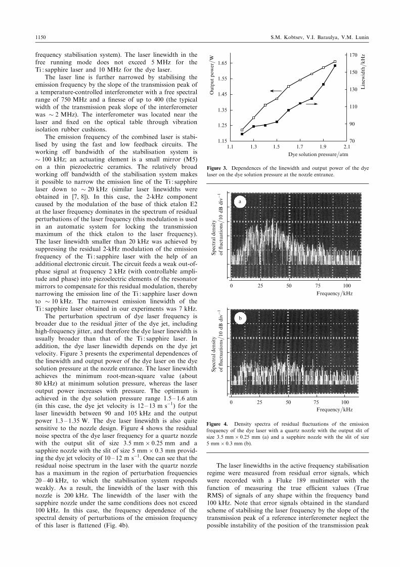
The perturbation spectrum of dye laser frequency isbroader due to the residual jitter of the dye jet, includinghigh-frequency jitter, and therefore the dye laser linewidth isusually broader than that of the Ti : sapphire laser. Inaddition, the dye laser linewidth depends on the dye jetvelocity. Figure 3 presents the experimental dependences ofthe linewidth and output power of the dye laser on the dyesolution pressure at the nozzle entrance. The laser linewidthachieves the minimum root-mean-square value (about80 kHz) at minimum solution pressure, whereas the laseroutput power increases with pressure. The optimum isachieved in the dye solution pressure range 1.5 ë 1.6 atm(in this case, the dye jet velocity is 12 ë 13 m sÿ1) for thelaser linewidth between 90 and 105 kHz and the outputpower 1.3 ë 1.35 W. The dye laser linewidth is also quitesensitive to the nozzle design. Figure 4 shows the residualnoise spectra of the dye laser frequency for a quartz nozzlewith the output slit of size 3:5 mm� 0:25 mm and asapphire nozzle with the slit of size 5 mm� 0:3 mm provid-ing the dye jet velocity of 10 ë 12 m sÿ1. One can see that theresidual noise spectrum in the laser with the quartz nozzlehas a maximum in the region of perturbation frequencies20 ë 40 kHz, to which the stabilisation system respondsweakly. As a result, the linewidth of the laser with thisnozzle is 200 kHz. The linewidth of the laser with thesapphire nozzle under the same conditions does not exceed100 kHz. In this case, the frequency dependence of thespectral density of perturbations of the emission frequencyof this laser is êattened (Fig. 4b).
The laser linewidths in the active frequency stabilisationregime were measured from residual error signals, whichwere recorded with a Fluke 189 multimeter with thefunction of measuring the true efécient values (TrueRMS) of signals of any shape within the frequency band100 kHz. Note that error signals obtained in the standardscheme of stabilising the laser frequency by the slope of thetransmission peak of a reference interferometer neglect thepossible instability of the position of the transmission peak
Outputpower� W
Linew
idth� kH
z
Dye solution pressure�atm
1.1 1.3 1.5 1.7 1.9 2.170
90
110
130
150
170
1.15
1.25
1.35
1.45
1.55
1.65
Figure 3. Dependences of the linewidth and output power of the dyelaser on the dye solution pressure at the nozzle entrance.
a
Frequency�kHz
0 25 50 75 100
Spectral
density
ofêuctuations� 10
dB
divÿ1
b
Frequency�kHz
0 25 50 75 100
Spectral
density
ofêuctuations� 10
dB
divÿ1
Figure 4. Density spectra of residual êuctuations of the emissionfrequency of the dye laser with a quartz nozzle with the output slit ofsize 3:5 mm� 0:25 mm (a) and a sapphire nozzle with the slit of size5 mm� 0:3 mm (b).
1150 S.M. Kobtsev, V.I. Baraulya, V.M. Lunin
itself. Therefore, the linewidths presented here are relative(with respect to the reference interferometer), although weassume that the absolute laser linewidths weakly differ fromthe relative linewidths measured in our experiments becauseof a high vibration isolation of the reference interferometerachieved due to its independent disposition.
5. Long-term drift of the laser line
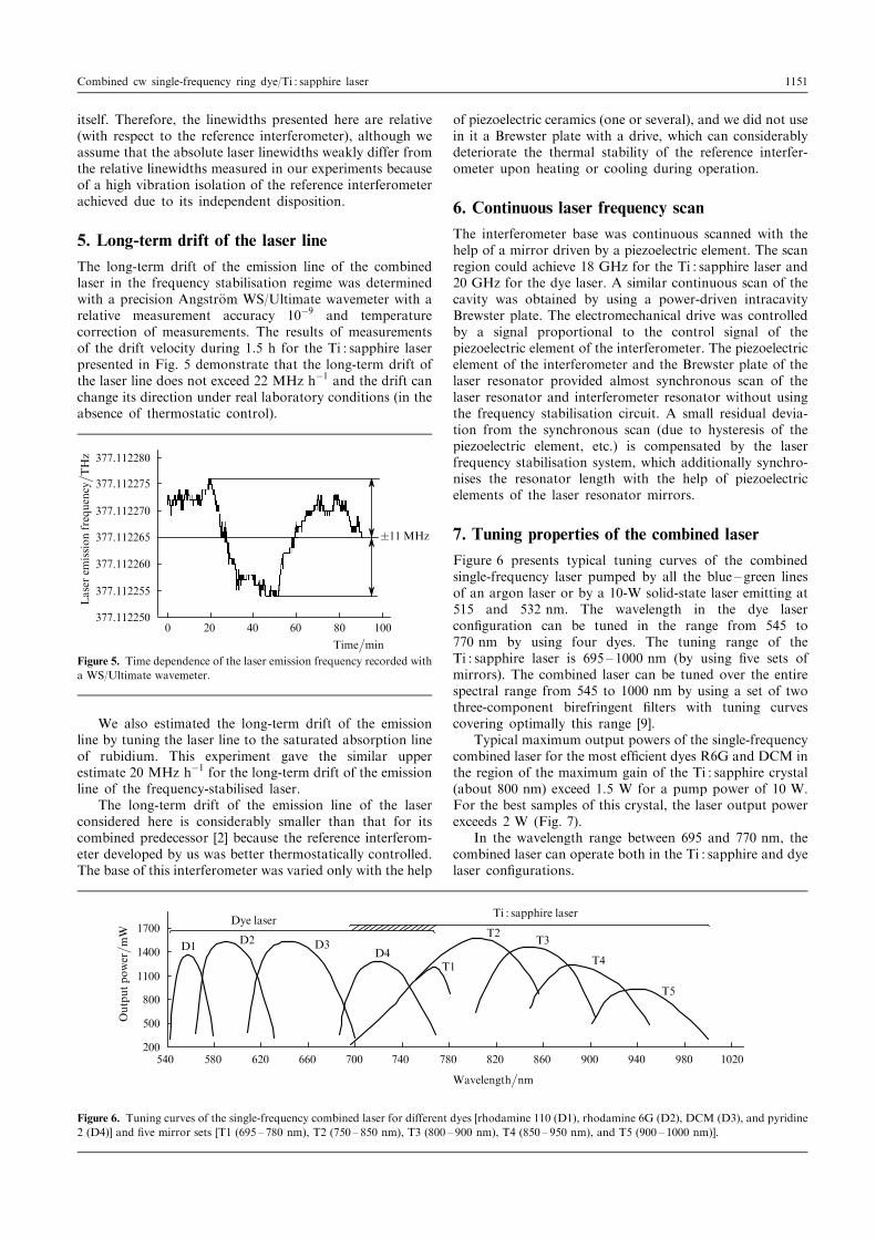
The long-term drift of the emission line of the combinedlaser in the frequency stabilisation regime was determinedwith a precision Angstr�om WS/Ultimate wavemeter with arelative measurement accuracy 10ÿ9 and temperaturecorrection of measurements. The results of measurementsof the drift velocity during 1.5 h for the Ti : sapphire laserpresented in Fig. 5 demonstrate that the long-term drift ofthe laser line does not exceed 22 MHz hÿ1 and the drift canchange its direction under real laboratory conditions (in theabsence of thermostatic control).
We also estimated the long-term drift of the emissionline by tuning the laser line to the saturated absorption lineof rubidium. This experiment gave the similar upperestimate 20 MHz hÿ1 for the long-term drift of the emissionline of the frequency-stabilised laser.
The long-term drift of the emission line of the laserconsidered here is considerably smaller than that for itscombined predecessor [2] because the reference interferom-eter developed by us was better thermostatically controlled.The base of this interferometer was varied only with the help
of piezoelectric ceramics (one or several), and we did not usein it a Brewster plate with a drive, which can considerablydeteriorate the thermal stability of the reference interfer-ometer upon heating or cooling during operation.
6. Continuous laser frequency scan
The interferometer base was continuous scanned with thehelp of a mirror driven by a piezoelectric element. The scanregion could achieve 18 GHz for the Ti : sapphire laser and20 GHz for the dye laser. A similar continuous scan of thecavity was obtained by using a power-driven intracavityBrewster plate. The electromechanical drive was controlledby a signal proportional to the control signal of thepiezoelectric element of the interferometer. The piezoelectricelement of the interferometer and the Brewster plate of thelaser resonator provided almost synchronous scan of thelaser resonator and interferometer resonator without usingthe frequency stabilisation circuit. A small residual devia-tion from the synchronous scan (due to hysteresis of thepiezoelectric element, etc.) is compensated by the laserfrequency stabilisation system, which additionally synchro-nises the resonator length with the help of piezoelectricelements of the laser resonator mirrors.
7. Tuning properties of the combined laser
Figure 6 presents typical tuning curves of the combinedsingle-frequency laser pumped by all the blue ë green linesof an argon laser or by a 10-W solid-state laser emitting at515 and 532 nm. The wavelength in the dye laserconéguration can be tuned in the range from 545 to770 nm by using four dyes. The tuning range of theTi : sapphire laser is 695 ë 1000 nm (by using éve sets ofmirrors). The combined laser can be tuned over the entirespectral range from 545 to 1000 nm by using a set of twothree-component birefringent élters with tuning curvescovering optimally this range [9].
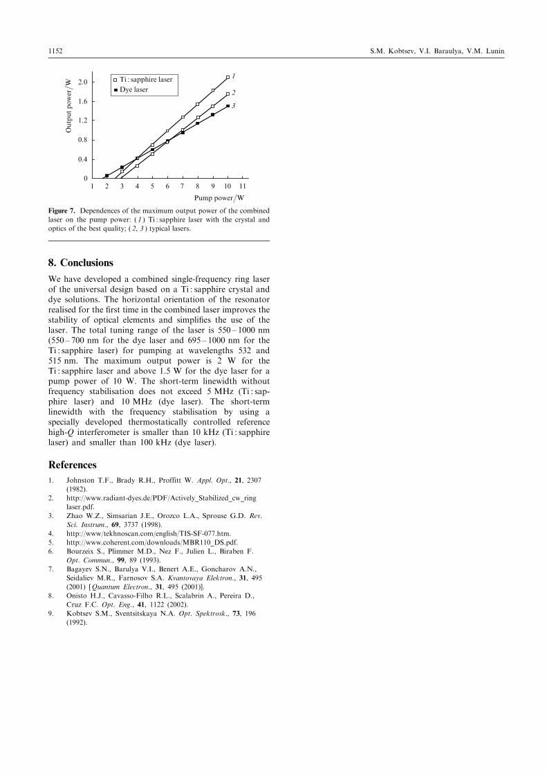
Typical maximum output powers of the single-frequencycombined laser for the most efécient dyes R6G and DCM inthe region of the maximum gain of the Ti : sapphire crystal(about 800 nm) exceed 1.5 W for a pump power of 10 W.For the best samples of this crystal, the laser output powerexceeds 2 W (Fig. 7).
In the wavelength range between 695 and 770 nm, thecombined laser can operate both in the Ti : sapphire and dyelaser conégurations.
0 20 40 60 80 100
Time�min
Laser
emissionfrequency� TH
z
�11MHz
377.112250
377.112255
377.112260
377.112265
377.112270
377.112275
377.112280
Figure 5. Time dependence of the laser emission frequency recorded witha WS/Ultimate wavemeter.
540 580 620 660 700 740 780 820 860
Wavelength�nm
Outputpower� mW
Dye laserTi : sapphire laser
900 940 980 1020200
500
1700
1400
1100
800
D1D2 D3
D4T1
T2T3
T4
T5
Figure 6. Tuning curves of the single-frequency combined laser for different dyes [rhodamine 110 (D1), rhodamine 6G (D2), DCM (D3), and pyridine2 (D4)] and éve mirror sets [T1 (695 ë 780 nm), T2 (750 ë 850 nm), T3 (800 ë 900 nm), T4 (850 ë 950 nm), and T5 (900 ë 1000 nm)].
Combined cw single-frequency ring dye/Ti : sapphire laser 1151
8. Conclusions
We have developed a combined single-frequency ring laserof the universal design based on a Ti : sapphire crystal anddye solutions. The horizontal orientation of the resonatorrealised for the érst time in the combined laser improves thestability of optical elements and simpliées the use of thelaser. The total tuning range of the laser is 550 ë 1000 nm(550 ë 700 nm for the dye laser and 695 ë 1000 nm for theTi : sapphire laser) for pumping at wavelengths 532 and515 nm. The maximum output power is 2 W for theTi : sapphire laser and above 1.5 W for the dye laser for apump power of 10 W. The short-term linewidth withoutfrequency stabilisation does not exceed 5 MHz (Ti : sap-phire laser) and 10 MHz (dye laser). The short-termlinewidth with the frequency stabilisation by using aspecially developed thermostatically controlled referencehigh-Q interferometer is smaller than 10 kHz (Ti : sapphirelaser) and smaller than 100 kHz (dye laser).
References1. Johnston T.F., Brady R.H., Proffitt W. Appl. Opt., 21, 2307
(1982).
2. http://www.radiant-dyes.de/PDF/Actively_Stabilized_cw_ring
laser.pdf.
3. Zhao W.Z., Simsarian J.E., Orozco L.A., Sprouse G.D. Rev.Sci. Instrum., 69, 3737 (1998).
4. http://www/tekhnoscan.com/english/TIS-SF-077.htm.
5. http://www.coherent.com/downloads/MBR110_DS.pdf.
6. Bourzeix S., Plimmer M.D., Nez F., Julien L., Biraben F.
Opt. Commun., 99, 89 (1993).
7. Bagayev S.N., Barulya V.I., Benert A.E., Goncharov A.N.,
Seidaliev M.R., Farnosov S.A. Kvantovaya Elektron., 31, 495(2001) [Quantum Electron., 31, 495 (2001)].
8. Onisto H.J., Cavasso-Filho R.L., Scalabrin A., Pereira D.,
Cruz F.C. Opt. Eng., 41, 1122 (2002).
9. Kobtsev S.M., Sventsitskaya N.A. Opt. Spektrosk., 73, 196(1992).
1 2 3 4 5 6 7 8 9 10 11
Outputpower� W
Pump power�W
Ti : sapphire laser
Dye laser
0
0.4
0.8
1.2
1.6
2.01
2
3
Figure 7. Dependences of the maximum output power of the combinedlaser on the pump power: ( 1 ) Ti : sapphire laser with the crystal andoptics of the best quality; ( 2, 3 ) typical lasers.
1152 S.M. Kobtsev, V.I. Baraulya, V.M. Lunin