Combination Unit (Model D) and Vacuum Power Mixer Plus...
12
Combination Unit (Model D) and Vacuum Power Mixer Plus (Model F) Use & Care Whip Mix Corporation • P.O. Box 17183 • Louisville, KY 40217-0183 USA 502-637-1451 • 800-626-5651 • Fax 502-634-4512 • www.whipmix.com
Transcript of Combination Unit (Model D) and Vacuum Power Mixer Plus...
1
Combination Unit (Model D) and Vacuum Power Mixer Plus (Model F)
Use & Care
Whip Mix Corporation • P.O. Box 17183 • Louisville, KY 40217-0183 USA 502-637-1451 • 800-626-5651 • Fax 502-634-4512 • www.whipmix.com

2
Parts
The Ortho Vacuum Power Mixer Plus:
1 – #6615 875 mL Vac-U-Mixer (650 g capacity)
1 – Handy-Holder Bowl Support
Combination Unit, complete with accessories:
1 – #6500 500 mL Vac-U-Mixer (350 g capacity)
1 – #4120 200 mL Vac-U–Spat (100 g capacity)
2 – #4085 Casting Ring, 11/4" O.D. x 13/8"
2 – #4081 Crucible Former
1 – 26 mL Plastic Water Graduate
1 – Stick Pliable Sticky Wax
2 – 50 gram Envelopes of Beauty-Cast Investment
Motor:1/4 HP Single Phase
1,725 RPM @ 60 Hz, 115V, 4.4A
1,425 RPM @ 50 Hz, 230V, 2.2A
Duty Cycle: 50%
Combination Unit
#6011 MufflerIteM # 06157
#6014C Motor SwItChIteM # 13455
#6380 BenCh Stand IteM # 06149(optIonal)
#6108 frICtIon drIve ChuCk (hIgh Speed)IteM # 06211
#6104a vIBrator SprIngIteM # 06432
Vacuum Power Mixer Plus
#6011 MufflerIteM # 06157
#6324 vaCuuM gaugeIteM # 06181
#6324 vaCuuM gaugeIteM # 06181
#6012 oIler unItIteM # 06254
#6012 oIler unItIteM # 06254
#6012-2 oIler JarIteM # 06351
#6012-2 oIler JarIteM # 06351
#5700 tuBIng and ConneCtIonSIteM # 09156
#5700 tuBIng and ConneCtIonSIteM # 09156
#6007 vIBrator knoBIteM # 06440
#6007 vIBrator knoBIteM # 06440
#6104a vIBrator SprIngIteM # 06432
#6014C Motor SwItChIteM # 13455
#6380 BenCh Stand IteM # 06149(optIonal)
#6125 vaC-u-tIMer IteM # 25585 (optIonal)
#6109 vIBrator retaInerIteM # 06556
#6109 vIBrator retaInerIteM # 06556
#6103 vIBrator rodIteM # 06424
#6103 vIBrator rodIteM # 06424
Standard parts packaged with all Vacuum Power Mixer Plus and all Combination Units are:
1 – #5700 21/4" Tubing with connection
1 – 4 oz. bottle of VV #56 Lubricant
1 – #6116 Mounting Bolts, package of 2
1 – Tube of Lubriplate
When purchasing specific units, they also include the following accessories:
1 – #4450 300 mL Vac-U-Mixer (150 g capacity)
1 – #6500 500 mL Vac-U-Mixer (350 g capacity)
Warranty:The Vacuum Power Mixer Plus and Combination Unit are covered by a standard Whip Mix three year warranty (US and Canada only). All parts and labor for three years on purchases made after 9/1/05.
Caution: Hot Surface
Caution: Refer to accompanying documents
A. Technical SpecificationsDimensions: Unit OnlyWeight: 24 lbs. (10.9 kg)
Width: 9 in. (22 cm)
Height: 16 in. (40 cm)
Bowl clearance (from counter) with handy holder: 10 in. (25.4 cm)
Depth: 9 in. (22 cm)
Dimensions: With Bench StandWeight: 30 lbs. (13.6 kg)
Width: 9 in. (22 cm)
Height: 26 in. (66 cm)
Recommended clearance with bench stand: 29 in. (73.7 cm)
Depth: 9 in. (22 cm)

3
oil wick will extend down into oil. Screw Oil Jar firmly into oiler top. Use only VV #56 Lubricant since other oils may harm the Vacuum Pump mechanism.
CAUTion: Do noT oVerfill SinCe oiler felTS MAy beCoMe oil-SoAkeD, reSUlTing in exCeSSiVe oil being DrAWn inTo The VACUUM PUMP WiTh A PoSSible reDUCTion of PUMP effiCienCy.
Push open end of plastic tubing over hose nipple on oiler unit.
The muffler is normally installed to discharge vertically, but if space is restricted, it can be pointed horizontally to the left or even downward.
Plug cord into electrical outlet. CAUTion: MAke SUre AVAilAble eleCTriCAl
VolTAge AnD CyCleS CorreSPonD WiTh ThoSe on MoTor DATA PlATe.
activates, the red button on the top edge of the motor will pop out slightly, signifying a thermal overload. Turn OFF the main power switch and wait 3-5 minutes then depress the red button. It should stay depressed when you release it. If it does not, wait another few minutes for the motor to cool down, and then try pushing in the red button. When it stays depressed, make sure there are no obstructions binding the shaft of the mixer motor before turning on the main power switch and resuming use of the mixer.
Switching—Manual and AutomaticThe units are equipped with a Manual Switch on the front of the gear housing. There is an automatic switch built into the low-speed Drive Chuck. The mixing bowl with a slotted Drive Nut is inserted into the low-speed Drive Chuck by aligning the slotted Drive Nut with the cross pin inside the Drive Chuck. The motor will start automatically when the slotted Drive nut on the mixing bowl assembly is pushed upward into the Drive Chuck. The motor will stop upon disengaging and the vacuum will drop. For high-speed mixing or to establish a vacuum, turn on the Manual Switch.
VibratorThe built-in Vibrator is sturdy and dependable — use it in a regular manner. All wear takes place on the #6103 Vibrator Rod rather than on the cam from which it operates. Therefore, replacement of the rod is required when loss of vibration is noted. To replace vibrator rod, release Vibrator Retainer #6109 (see diagram page 2). Swing arm up and remove worn rod. In some instances it may be necessary to grasp rod with pliers and pull out with a twisting motion. Insert new rod in hole.
b. installationMountingWhip Mix Vacuum Mixing and Investing Units are designed for operation in a vertical position. If it is to be attached to a wooden wall or cabinet, lag bolts and washers are suitable for mounting. For a plastered wall, the use of a wooden board long enough to span the wall studs is recommended. A #6380 Bench Stand, which fastens onto a counter, is available separately. When mounting, be sure to leave clearance above the vacuum pump for service.
AssemblyPlease note the Drive Shaft must point downward. Keep minimum distance of 9" between the end of the Drive Chuck and bench or table to allow access for the larger #6600 and #7600 Vac-U-Mixers.
Pour Whip Mix VV #56 Lubricant into Oil Jar and fill to the level mark on jar. Make sure gasket is in place inside oiler top and
D. featuresDrive ChucksThe Vacuum Power Mixer Plus is equipped with a low-speed (430 RPM) Drive Chuck for vacuum-mixing of plasters, stones, die materials, investments and alginates, with the Vac-U-Mixer (200 mL, 300 mL, 500 mL, 875 mL or 1200 mL size) and Flexible Vac-U-Mixer (350 g or 650 g).
The Combination Unit is equipped with two separate Drive Chucks.
(a) The Rear Chuck turns at high speed (1,725 RPM) for vacuum-mixing with the Vac-U-Mixer and investing with the Vac-U-Spat (200 mL or 300 mL sizes).
(b) The Front Chuck turns at low speed (430 RPM) for vacuum-mixing plasters, stones, die materials, investments in larger quantities, and alginates with the Vac-U-Mixer (200 mL, 300 mL, 500 mL, 875 mL or 1,200 mL sizes).
The Vac-U-Spat has a round Drive Nut with a rubber “O” Ring for friction drive. It fits into the rear high-speed Drive Chuck #6108. See page 6 for detailed instructions for operation of the Vac-U-Spat.
Vacuum PumpThe 1/4 HP motor drives the Vacuum Pump, located on the top of the unit, and the low-speed Drive Chuck through the gear housing on the lower end. The Vacuum Pump will produce a vacuum of 26" to 28" Hg (66 to 71 cm Hg) at sea level (deduct 1" for each 1,000 feet elevation above sea level) and therefore can be used as a high vacuum source for other equipment.
overload SwitchThe Electric Motor is equipped with an internal thermal Overload Switch to protect it from overheating. If the overload switch
C. Caution Do noT inSerT Any PADDle ASSeMbly inTo
DriVe ChUCk WiThoUT boWl in PlACe.
Do noT inSerT Any objeCT oTher ThAn An ASSeMbleD Mixing boWl inTo A DriVe ChUCk AT Any TiMe.
before PlUgging UniT in, CheCk eleCTriCAl SUPPly ChArACTeriSTiCS WiTh MoTor ChArACTeriSTiCS.
if TherMAl oVerloAD SWiTCh ShUTS DoWn MoTor, iMMeDiATely MoVe MAnUAl SWiTCh To “off” PoSiTion AnD CheCk for CAUSe of oVerloAD.
rUn UniT AfTer eACh USe for one MinUTe or More To PUrge WATer VAPor AnD lUbriCATe PUMP.
Do noT fill oil jAr AboVe oil leVel MArk.
USe only The VV #56 lUbriCAnT fUrniSheD WiTh yoUr UniT. oTher oilS MAy hArM The VACUUM PUMP.
The roTor iS glUeD To The ShAfT of The MoTor — Do noT ATTeMPT To reMoVe iT. SenD MoTor To The fACTory for Any rePAir WhiCh inVolVeS reMoVAl of roTor. oTherWiSe, DAMAge To oTher PArTS of MoTor MAy reSUlT. All oTher PUMP PArTS CAn be reMoVeD for SerViCe AS neeDeD.

4
e. operation
Parts
noTe: TWo “o” ringS #1 (#4008) Are inSTAlleD on PADDle ShAfT of All SizeS exCePT The #7600, WhiCh reqUireS “o” ringS #2 (#5702).
MixingThe Vac-U-Mixer has been thoroughly tested and is ready for use upon unpacking.
1. Before using, rinse Bowl and Lid assembly. Shake off excess water. This is most important whenever water and material are measured. Proportion water and material into bowl according to manufacturer’s directions. Incorporate thoroughly with hand spatula, no dry powder or large lumps should remain.
Vac-U-Mixer
Capacity Volume Gypsum Alginate Model Number (mL) (grams) (scoops)
#6400 200 25–100 1–2
#4450 300 25–150 1–3
#6500 500 50–350 2–5
#6600 875 50–800
#7600 1,200 100–1,000
#6606 StaInleSS Steel paddle IteM # 09040
#6602 plaStIC Bowl IteM # 09032
875 ml #6600
#7602 StaInleSS Steel Bowl IteM # 07374
1,200 ml #7600
#6865 drIve nut IteM # 09105
#7601 Metal lId IteM # 09059
#7605 “o” rIng #8 IteM # 09083
#7606 StaInleSS Steel paddle IteM # 09075
300 ml #4450
#4452 plaStIC Bowl IteM # 07609
StaInleSS Steel paddle #4458 (algInate) IteM # 08923#4455 (gypSuMS) IteM # 08931
200 ml #6400
#6375 drIve nut IteM # 09091
#6375 drIve nut IteM # 09091
#6401 plaStIC lId IteM # 08885
#6401 plaStIC lId IteM # 08885
#4006 “o” rIng #4 IteM # 07390
#4006 “o” rIng #4 IteM # 07390
#4002 plaStIC Bowl IteM # 07595
#6406 StaInleSS Steel paddle IteM # 08907
#6506 StaInleSS Steel paddle (gypSuMS) IteM # 08982
500 ml #6500
#6501 plaStIC lId IteM # 08958
#6501 plaStIC lId IteM # 08958
#6502 plaStIC Bowl IteM # 08974
#6505“o” rIng #6 IteM # 09024
#6505“o” rIng #6 IteM # 09024
Vac-U-MixerThe Vac-U-Mixer is available in the five sizes shown. It is designed to give dense, smooth, mixes of plaster, stone, investment, alginate, etc., by mixing under vacuum.
2. Place Lid on Bowl, rotate Bowl clockwise to engage locking tabs, and/or press together to help seat the Bowl on “O” Ring (rubber gasket) in Lid.
3. Connect vacuum by slipping metal nozzle at end of Vacuum Hose into opening on top of Lid.
Mixing at low Speed
4. Holding Bowl and Lid together, insert the slotted Drive Nut into Drive Chuck for automatic start. After starting, move the Manual Switch to the “On” position so the Pump continues to run after the Vac-U-Mixer is disengaged.
Mixing at high Speed
Turn Pump “On” to establish vacuum. Insert friction Drive Nut #4109 into turning Drive Chuck — rubber “O” Ring on Drive Nut must be dry for best results.
#6375 drIve nut IteM # 09091
#6375 drIve nut IteM # 09091
CAUTion: hoT SUrfACe When in oPerATion

5
Suggested Mixing Times (seconds)
@ High Speed @ Low Speed Material 1,725 RPM 430 RPM
Plaster, Stone, Die Material 10–15 20–30
Gypsum Investment 20–30 40–50
Phosphate Investment 30–45 60–90
Alginate Not Suggested 12–15
Ideal spatulation time can be determined by a few experimental test runs, as this depends on the material and the consistency of mix used by the individual.
for AlginATeS SkiP To STeP 9.
5. With Motor still running, disengage Vac-U-Mixer from Drive Chuck. Vibrate mix to bottom of Bowl and slowly break vacuum by turning Manual Switch to “Off” position then removing Trap Cap from Vac-U-Mixer. Return unit to “On” position, let Motor run for approximately one minute to purge water vapor from Pump and to re-oil.
6. Separate Paddle from mix by vibrating as Lid and Paddle Assembly is removed.
MaintenanceLubriplate (lubricating grease) has been applied to the Shaft and “O” Rings of the Vac-U-Mixer before leaving our plant. This should be sufficient for several weeks. Thereafter, Lubriplate should be applied lightly several times a year. For this purpose, unscrew Drive Nut on top of Paddle Shaft, grasp Paddle and pull from Lid. Wipe off shaft and pull a piece of cloth through bearing. Apply Lubriplate to “O” Ring #1 on shaft and top of bearing Lid. After reassembling, wipe away excess grease. A tube of Lubriplate has been included with shipment for this purpose.
“O” Rings provide leakproof vacuum needed. Replacement will be necessary depending upon use. Lubriplate applied lightly to the “O” Ring #1 on the end of the Metal Trap Cap makes insertion and removal easier and increases the life of the “O” Ring.
7. Pour mix as usual, taking care that no air bubbles are trapped when pouring.
8. Rinse Vac-U-Mixer parts thoroughly at once under running water — no need for drying before next use.
9. For Alginates, break vacuum immediately and use mix in conventional manner. it is still important to let Vacuum Pump run for approximately one minute to flush water vapor and re-oil. Allow excess material on Paddle and Bowl to set thoroughly before cleaning since the set alginate will peel away easily.
For mixing Alginates, special Flat Paddles are available for 200 mL and 500 mL sizes that facilitate the removal of material from the Paddle for filling the impression tray. The Paddle of the 300 mL size is Teflon-coated to promote easy cleaning.
noTe: PhoSPhATe inVeSTMenTS AnD AlginATeS CAn ConTAMinATe gyPSUM MATeriAlS, SerioUSly AffeCTing Their Working ProPerTieS. Therefore, iT iS STrongly reCoMMenDeD ThAT SePArATe Mixing boWlS be USeD AnD MArkeD To AVoiD ThiS PoSSibiliTy.
6
Parts
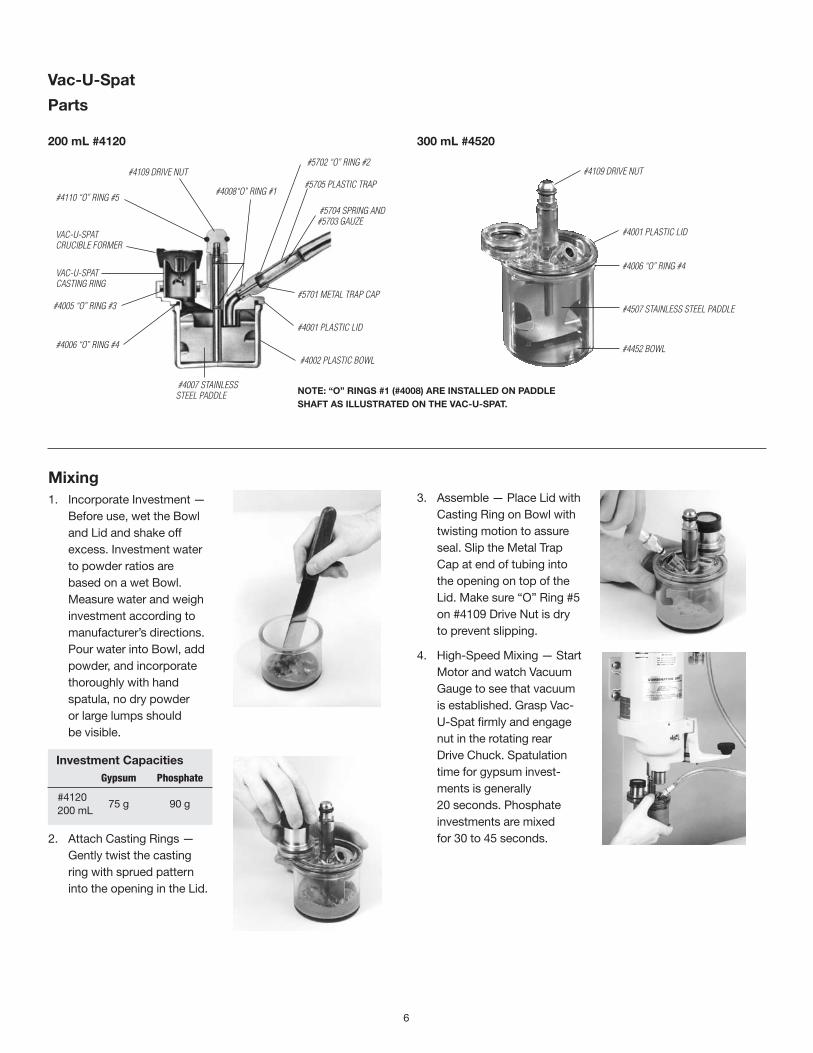
Vac-U-Spat
3. Assemble — Place Lid with Casting Ring on Bowl with twisting motion to assure seal. Slip the Metal Trap Cap at end of tubing into the opening on top of the Lid. Make sure “O” Ring #5 on #4109 Drive Nut is dry to prevent slipping.
4. High-Speed Mixing — Start Motor and watch Vacuum Gauge to see that vacuum is established. Grasp Vac-U-Spat firmly and engage nut in the rotating rear Drive Chuck. Spatulation time for gypsum invest-ments is generally 20 seconds. Phosphate investments are mixed for 30 to 45 seconds.
Mixing1. Incorporate Investment —
Before use, wet the Bowl and Lid and shake off excess. Investment water to powder ratios are based on a wet Bowl. Measure water and weigh investment according to manufacturer’s directions. Pour water into Bowl, add powder, and incorporate thoroughly with hand spatula, no dry powder or large lumps should be visible.
investment Capacities Gypsum Phosphate
#4120 75 g 90 g
200 mL
2. Attach Casting Rings — Gently twist the casting ring with sprued pattern into the opening in the Lid.
200 ml #4120 300 ml #4520
noTe: “o” ringS #1 (#4008) Are inSTAlleD on PADDle ShAfT AS illUSTrATeD on The VAC-U-SPAT.
#4109 drIve nut
#4001 plaStIC lId
#4006 “o” rIng #4
#4507 StaInleSS Steel paddle
#4452 Bowl
#4007 StaInleSS Steel paddle
#4006 “o” rIng #4
#4005 “o” rIng #3
vaC-u-Spat CaStIng rIng
vaC-u-Spat CruCIBle forMer
#4110 “o” rIng #5
#4109 drIve nut
#4008“o” rIng #1
#5702 “o” rIng #2
#5705 plaStIC trap
#5704 SprIng and #5703 gauze
#5701 Metal trap Cap
#4001 plaStIC lId
#4002 plaStIC Bowl

7
Tips1. It is necessary to wet Bowl and Lid before mixing measured
water and powder. Shaking off excess water will prevent dilution of investment mix. Wetting also facilitates insertion of the Casting Ring.
2. If the Casting Ring is not completely filled after investing, fill with investment mix remaining on Lid. Next time, vibrate a few seconds longer when filling ring.
3. “O” Rings are the “Heart of the Vac-U-Spat.” Practically all the wear and abrasion are confined to the replaceable “O” Ring #1 on the Shaft, Metal Trap Cap, and #4109 Drive Nut. After appreciable use and wear, replacement is necessary.
4. If working vacuum is not obtained quickly, twist Lid on the Bowl with a little pressure, or twist Casting Ring into its seat.
5. If sufficient vacuum is not obtained as outlined above, hold thumb over Metal Trap Cap and check Gauge reading. If incomplete vacuum is found at this point, unscrew Metal Trap Cap and see that “O” Ring #2 is found therein and properly seated. Screw cap back on and test. If this fails, refer to page 9.
MaintenanceFollow same procedures described for the Vac-U-Mixer on page 5.
5. Invest — With Motor still running, disengage Vac-U-Spat. Vibrate investment to bottom of Bowl tilting Vac-U-Spat toward Casting Ring. Check that Paddle is not blocking entry to ring. Place rim of Lid, which holds casting ring on vibrator knob. Gradually tilt Bowl to 45° position and vibrate investment into the ring. Continue to vibrate for 5 to 10 seconds after the ring is filled.
6. Release Vacuum — With Motor still running, hold Vac-U-Spat inverted and break vacuum by pulling out vacuum tubing with a twisting motion. Let Motor run for approximately one minute more to flush water vapor from Pump and to lubricate.
7. Remove Ring — Still hold-ing Vac-U-Spat inverted, grasp filled Casting Ring and remove by gently twisting and pulling down-ward. If Hygroscopic Technique is used, ring should be placed in waterbath (Hygrobath) immediately. Otherwise, let invested ring benchset.
8. Wash Vac-U-Spat Parts— Lid, Bowl and hand spatula should be washed thor-oughly at once under running water. For subse-quent use, make sure "O" Ring #5 on #4109 drive nut is dry to prevent slipping.
8
f. MaintenancePumpRegardless of the mixing equipment used, it is most important to allow the units to run for approximately one minute after each use. During spatulation under vacuum, water vapor is drawn into the Vacuum Pump. If the unit is shut off immediately, this vapor condenses to water as the pressure returns to atmospheric. By running the unit with the vacuum tubing open, air is pumped through, thus purging the water vapor from the Pump. At the same time, airflow through the Oiler Unit carries oil vapor into the Pump keeping it properly lubricated. If water accumulates in the Vacuum Pump, rusting can occur and this, and the mixture of oil and water, can cause a loss of vacuum. If this happens, refer to the service instruction on pages 9–11.
Cleaning PumpTo clean Pump a maintenance procedure which does not require dismantling of the Pump:
1. Remove Oil Jar.
2. Remove Muffler and Oiler Unit.
3. Cover Muffler hole with rag.
4. Turn Motor on. One drop at a time, slowly add one tablespoon of mineral spirits into the Oiler Unit hole. Let unit run for a minute — residues in Pump will exhaust into rag along with mineral spirits.
5. Repeat addition of mineral spirits.
6. With Motor running, place finger over Oiler Unit hole and read Gauge. A higher gauge reading indicates the vanes are now moving freely.
7. With Motor running, slowly add 1/2 tablespoon of VV #56 Lubricant through Oiler Unit opening/hole.
8. Place finger over hole and check vacuum gauge. Normal vacuum over 26" Hg should be indicated. Reassemble Muffler and Oiler Unit. If vacuum remains low, see page 10 for Pump repair procedures.
9. Replace felts every two years.
10. Replace vanes every five years.
Vacuum PressureIf at any time vacuum pressure drops for unknown reasons (other than leaks in connections or mixing units), unscrew Gauge (use wrench on boss on back of Gauge) and put 4 or 5 drops of VV #56 Lubricant in opening of motor housing. Then put Gauge
back, screwing in tightly. Turn on Motor and let it run for one minute or more. Vacuum pressure should be normal again. If this operation does not restore vacuum, refer to service instructions on pages 9–11.
oil jarKeep clean VV #56 Lubricant in Oil Jar to level mark and replace when dirty (at least every six months). Use only Whip Mix VV #56 Lubricant in Oil Jar to maintain proper lubrication in vacuum chamber and prevent rusting of Pump parts. The units do not require other oiling or greasing at any time. Lifetime sealed bearings on the Motor, Drive Shaft, and reducing gears are designed for continuous operation and need no lubrication.
Quick, sure vacuum can only be obtained with no leaks — check Oil Jar and tubing connections occasionally for tightness. Vacuum will vary due to atmospheric conditions (barometric pressure) — reading on Vacuum Gauge may be high one day and lower on another.
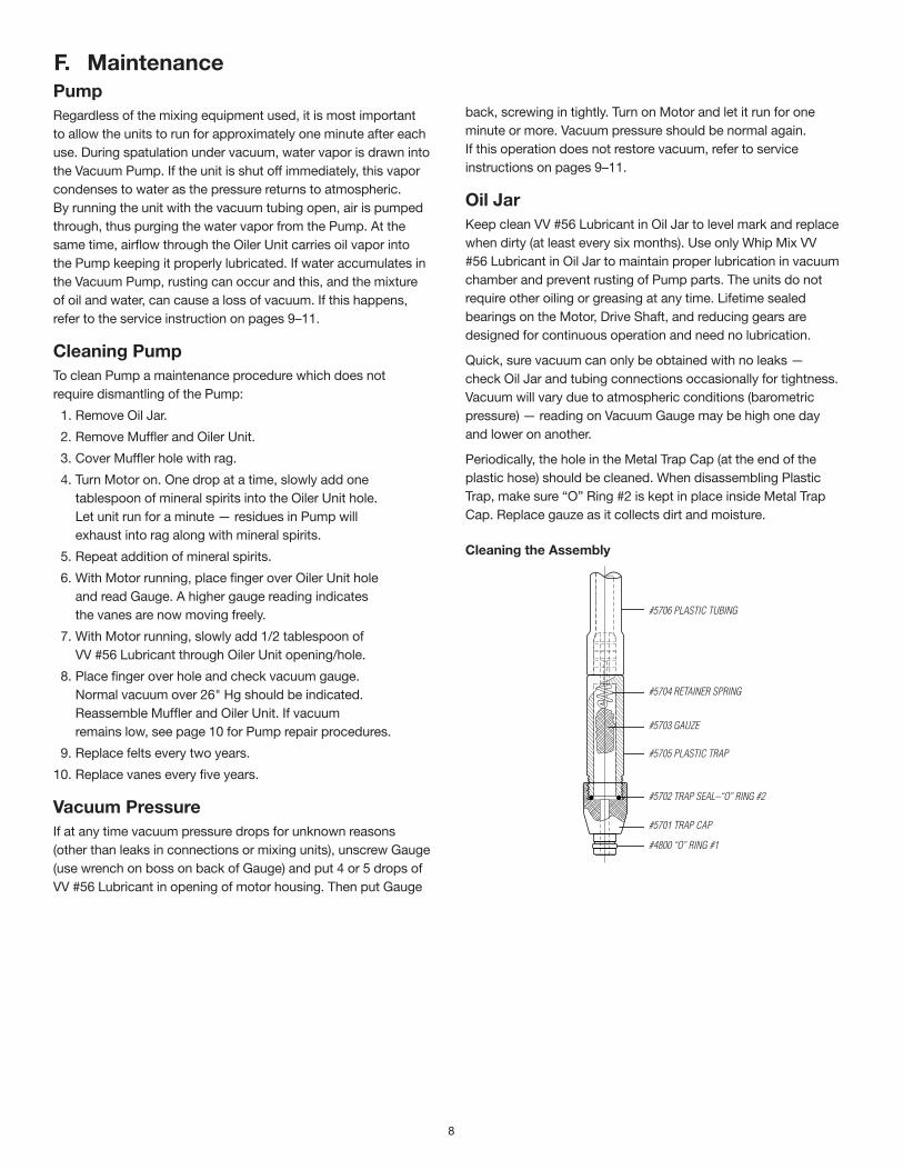
Periodically, the hole in the Metal Trap Cap (at the end of the plastic hose) should be cleaned. When disassembling Plastic Trap, make sure “O” Ring #2 is kept in place inside Metal Trap Cap. Replace gauze as it collects dirt and moisture.
#5706 plaStIC tuBIng
#5704 retaIner SprIng
#5703 gauze
#5705 plaStIC trap
#5702 trap Seal–“o” rIng #2
#5701 trap Cap
#4800 “o” rIng #1
Cleaning the Assembly

9
if the Vacuum is normal (over 26" hg), there may be a leak in the Mixing bowl or vacuum connection. Check for:
1. Worn or missing “O” Ring #1 on #5701 Metal Trap Cap. (Replace)
2. “O” Ring in Lid worn or positioned unevenly in groove. (Replace or if uneven, remove and clean material out of groove, then reinsert “O” Ring.)
3. Cracked Lid or Bowl. (Replace)
4. Warped Lid or Bowl. (Replace)
5. Leak around Paddle Shaft due to worn bearing or worn “O” Rings on Shaft. Grasp Paddle in hand and unscrew Drive Nut with pliers — thread direction may be right or left. Pull a rag through bearing to clean, grease Shaft with Lubriplate, and reassemble. The fit of the Shaft in the bearing should be tight. Any side play indicates a worn bearing. (Replace Lid)
low Vacuum
g. Troubleshooting
Vacuum Pump
rotor nearly touCheS puMp Body at thIS poInt. the puMp Body Can Be Moved when puMp Body SCrewS are looSened SlIghtly. teSt to aSSure proper ClearanCe By turn-Ing Motor Shaft By hand. after fInal aSSeMBly of puMp end plate, CheCk By turnIng drIve ChuCk By hand.
#6023 rotor DO NOT REMOVE — to Be reMoved only By faCtory.
#6027 puMp Body
#6010 vane
two #6028 puMp Body SCrewS hold puMp In poSItIon and are a MeanS of adJuStIng Clear-anCe Between puMp and rotor.View with #6025 end
Plate removed
MountIng BraCket
#6027 puMp Body
#6028 puMp Body SCrew
#6023 rotor
#6010 vane, Set of 4
#6025 end plate
#6026 end plate SCrew
#6099 gaSket
COaT NEw VaNEs wiTh VV #56 LubRiCaNT whEN iNsERTiNg.
#6010 VaNE EDgE wiTh sMaLL NOTCh MusT pOiNT TOwaRD CENTER Of ROTOR.
NEVER REMOVE ThE puMp MOuNTiNg fROM ThE MOTOR.
consistently produce a vacuum of 26" to 28" Hg at sea level. Deduct 1" for each 1,000' elevation above sea level. Turn unit on, place finger over end of vacuum line, and check Vacuum Gauge reading.
Before removing Pump end plate because of low vacuum, make sure there are no leaks due to cracked Oil Jar lip or loose connections. Often, several drops of VV #56 Lubricant applied directly into the Pump by removing the Vacuum Gauge will raise the vacuum. During normal operation, the Vacuum Pump will
if the same low vacuum occurs, check for:
1. Chipped or cracked lip on Oil Jar. (Replace)
2. Missing or broken #6040 Cork Gasket. (Replace)
3. Cracked #5705 Plastic Trap. (Replace)
4. Missing “O” Ring #2, located inside #5071 Metal Trap Cap. (Replace)
5. Loose fittings on Oiler-Filter Unit. (Replace)
6. Gummy Pump — vanes not sliding in slots. (Clean Pump)
7. Worn #6010 Vanes. (Replace)

10
Avoid The Problems of low Vacuum With These Simple Maintenance Tips1. As the “Reminder” label on the Motor suggests, run the unit
at least one minute after each use to purge water vapor and lubricate the Pump. (This is especially important when unit is run less than five times each day.)
2. Replace lubricant in Oil Jar every six months, or earlier if lubricant appears dirty.
3. At the same time the oil is changed, unscrew the plastic felt support from the baffle to check condition of the felt filter set. Felts should be clean and dry. Rinse felts in solvent to remove dirt and oil. Squeeze in a towel to dry. It is recommended felts be replaced every two years.
4. Replace gauze in #5705 Plastic Trap whenever it becomes wet or if vacuum gauge reading goes over 15" Hg.
5. Replace “O” Rings as they become worn.
6. Replacement parts most commonly needed are provided in the Vac-U-Care Maintenance Kit. See page 12. Please visit www.whipmix.com for a video on the installation of the Vac-U-Care Maintenance Kit.
Cleaning Vacuum ChamberWhen vacuum has dropped or motor appears locked, the Pump vacuum chamber should be cleaned. Generally, this is caused by sticking vanes as a result of moisture in the vacuum chamber. Failure to run the Motor for approximately one minute after each use is usually the cause. Unscrew Oil Jar and set aside. Remove six end plate screws and lift off the pump end plate. Remove the four vanes from the Rotor and wipe them clean of dirt and moisture and clean the slots in the Rotor. With a rag or towel, clean the vacuum chamber and the end plate. Dip each vane in VV #56 Lubricant and re-insert, making sure the notched edge points toward the Shaft (see drawing on page 9).
For checking, turn the Shaft at the opposite end by hand and then replace the end plate. Fasten all six screws until almost tight, then tighten all screws evenly and check again for binding by turning the Shaft by hand before starting the Motor. If the vacuum is still low, vane replacement or resetting of clearance between Pump body and Rotor is indicated (see below).
Vane replacementProceed in the same manner as outlined above for cleaning and insert new vanes instead. Replacement vanes are Part #6010 (set of 4). It is recommended that the vanes be replaced every five years. For a video on replacing the vanes visit www.whipmix.com
Setting Clearance between Pump ring and rotorWith end plate removed, loosen the two screws holding the Pump body. Tap body slightly until it gently rubs the Rotor. For checking, turn Motor Shaft by hand. After clearance has been corrected, tighten the holding screws. Reassemble Pump end plate and check for binding by turning Shaft again by hand before operating.
Pump interior Should Always be Wet With lubricantIf Pump chamber is dry when Pump end plate is taken off, check to see that oil wick is properly located in the Oiler Unit. The wick must touch the lubricant in the Oil Jar and must also extend into the pipe nipple that connects the Oiler Unit to the Pump.
Cross Section of #6112 oiler-filter Unit
#6012-7 1/8" pIpe nIpple
#6012-4 oIl wICk Should extend Into pIpe nIpple ConneCtIng oIler to puMp
#6012-1 oIler top
#6040 Cork gaSket (CraCked or ChIpped Jar lIp wIll CauSe loSS of vaCuuM at Seal)
#6012-6 1/8" Street elBow
#6012-9hose nipple
#7502 “o” rIng #7
#6013a Baffle preventS MoISture dropletS froM ContaCtIng felt fIlter
#6012-15 felt fIlter Set aSSureS only Clean aIr wIll enter puMp ChaMBer
#6012-8 plaStIC felt Support
#6012-2 plaStIC oIl Jar
oil Splatter from MufflerIf too much lubricant is supplied to the Pump, any excess will be pumped into the Muffler. Generally, this will occur when the felt filter in the Oiler Unit has become wetted with lubricant or the oil wick extends too far into the pipe nipple. Oiler Unit felts can be dried by squeezing out excess lubricant with a dry cloth. The oil wick may be pulled out about 1/8". Care should be taken to keep lubricant level low enough so none will contact the felt filter.
rusty Pump interiorRust can form inside the Pump when insufficient lubricant reaches the chamber of the Pump (see “Pump Interior Should Always Be Wet With Lubricant”) or when water vapor is drawn into the unit. This may be caused by failure to run Motor after each use, by wet gauze in the Plastic Trap, or when the felt filter in the Oiler Unit has become wet. Any rust should be cleaned off all surfaces with very fine emery paper, and all surfaces oiled before reassembly.
Motor hums but Will not TurnUsually this occurs with a rust-bound Rotor (See “Rusty Pump Interior”). Turn starting switch off immediately to avoid damaging the Motor.
11
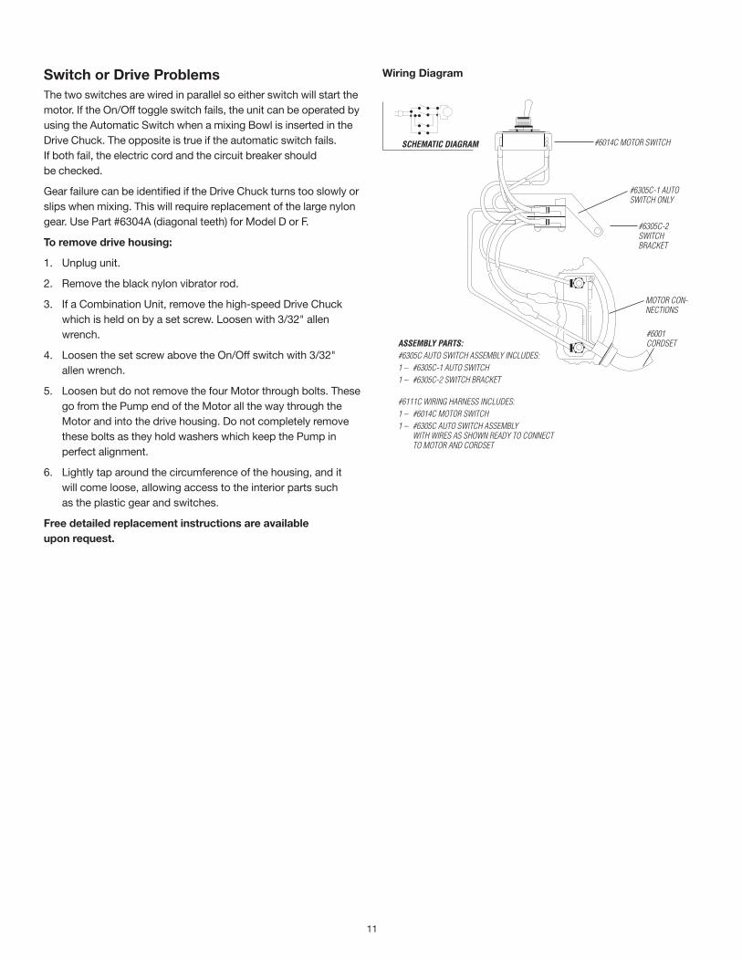
sChEMaTiC DiagRaM #6014C Motor SwItCh
#6305C-1 auto SwItCh only
#6305C-2 SwItCh BraCket
Motor Con-neCtIonS
#6001 CordSetassEMbLy paRTs:
#6305C auto SwItCh aSSeMBly InCludeS:1 – #6305C-1 auto SwItCh1 – #6305C-2 SwItCh BraCket
#6111C wIrIng harneSS InCludeS:1 – #6014C Motor SwItCh1 – #6305C auto SwItCh aSSeMBly
wIth wIreS aS Shown ready to ConneCt to Motor and CordSet
Wiring DiagramSwitch or Drive ProblemsThe two switches are wired in parallel so either switch will start the motor. If the On/Off toggle switch fails, the unit can be operated by using the Automatic Switch when a mixing Bowl is inserted in the Drive Chuck. The opposite is true if the automatic switch fails. If both fail, the electric cord and the circuit breaker should be checked.
Gear failure can be identified if the Drive Chuck turns too slowly or slips when mixing. This will require replacement of the large nylon gear. Use Part #6304A (diagonal teeth) for Model D or F.
To remove drive housing:
1. Unplug unit.
2. Remove the black nylon vibrator rod.
3. If a Combination Unit, remove the high-speed Drive Chuck which is held on by a set screw. Loosen with 3/32" allen wrench.
4. Loosen the set screw above the On/Off switch with 3/32" allen wrench.
5. Loosen but do not remove the four Motor through bolts. These go from the Pump end of the Motor all the way through the Motor and into the drive housing. Do not completely remove these bolts as they hold washers which keep the Pump in perfect alignment.
6. Lightly tap around the circumference of the housing, and it will come loose, allowing access to the interior parts such as the plastic gear and switches.
free detailed replacement instructions are available upon request.

MPL30480 02/10
h. Accessories
Vac-U-TimerThe Vac-U-Timer will accurately time your mixing and other laboratory operations.
• Minutesandsecondsprogrammableup to 99 minutes/59 seconds with responsive touch-tone buttons.
• Easytoactivatealarmandmemoryfunction.
• Velcro® back easily affixes Vac-U-Timer to your mixing unit or any convenient surface.
• Timerautomaticallyresetsattheendoftiming cycle.
Item # 25585
bench StandBench Stand #6380 is available for bench-top mounting.
Item # 06149
Vac-U-Care Maintenance kitWhen it comes to taking care of any kind of machinery or equipment, a little maintenance goes a long way. So if your Whip Mix Combination Unit or Vacuum Power Mixer Plus Unit has yellow, oily tubing or your Vacuum Gauge is not reading as high as it should, it’s time to order our simple do-it-yourself Vac-U-Care Maintenance Kit.
Item # 28398
The kit includes:#5700 Tubing and Connections4 oz. VV #56 Lubricant#6010 Vanes (Set of 4)#4008 “O” Ring #1 (Pkg. 6)#4079 Lubriplate (1 Tube)#6011-7 Exhaust Trap#6012-15 Felt Set for Oiler Unit#6012-4 Wick#6040 Cork Gasket (1)
flexible Vacuum Mixing bowls
Designed to work with all Whip Mix vacuum mixers. With just a firm squeeze, the technician can crack and release without damaging the bowl. Available in 350g and 650g bowls.
Item# DescriptionFor Combination Unit and Vacuum Power Mixer Plus(Lid & Paddle Assembly Included)15665 #6720 350g Flexible Vac-U-Mixer 15667 #6750 650g Flexible Vac-U-Mixer
Flexible Bowl(No Lid & Paddle Assembly)15670 #6702A 350g Flexible Bowl15675 #6752 650g Flexible Bowl
Spatulas15677 #6712 Spatula Plastic Straight (For use with Flexible-Vac-U-Mixer)15680 #6711 Spatula Plastic Round (For use with Standard-Vac-U-Mixer)
handy-holder Vac-U-MixerFor use with the Ortho Power Vacuum Mixer Plus.
500 ml #6515
#6516 plaStIC lId IteM # 15482
#6516 plaStIC lId IteM # 15482
#6393 drIve nutIteM # 15555
#6393 drIve nutIteM # 15555
875 ml #6615


![Untitled-1 [] › files › product_docs › ... · Title: Untitled-1 Author: Lehel Created Date: 7/15/2014 10:36:08 AM](https://static.fdocuments.in/doc/165x107/5f20f56d1af47d5cda7d5648/untitled-1-a-files-a-productdocs-a-title-untitled-1-author-lehel.jpg)