COMBINATION EJECTOR/VACUUM Texaco GEMS E-1M and E-10. The liquid ring vacuum pumps and compressors...
16
Transcript of COMBINATION EJECTOR/VACUUM Texaco GEMS E-1M and E-10. The liquid ring vacuum pumps and compressors...
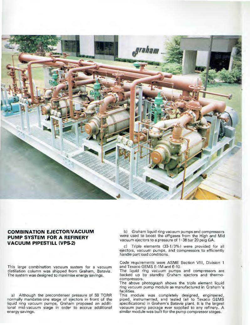
COMBINATION EJECTOR/VACUUM PUMP SYSTEM FOR A REFINERY VACUUM PIPESTILL (VPS2)
This large combination vacuum system for a vacuum distillation column was shipped from Graham, Batavia. The system was designed to maximise energy savings.
a) Although the precondenser pressure of 59 TORR normally mandates one stage of ejectors in front of the liquid ring vacuum pumps, Graham proposed an additional mid-vacuum stage in order to accrue additional energy savings.
b) Graham liquid ring vacuum pumps and compressors were used to boost the offgases from the High and Mid vacuum ejectors to a pressure of 1·38 bar 20 psig GA.
c) Triple elements (33-1 / 3%) were provided for all ejectors, vacuum pumps, and compressors to efficiently handle part load conditions.
Code requirements were ASME Section VIII, Division 1 and Texaco GEMS E-1M and E-10 . The liquid ring vacuum pumps and compressors are backed up by standby Graham ejectors and thermocompressors. The above photograph shows the triple element liquid ring vacuum pump module as manufactured in Graham's facilities . This module was completely designed, engineered , piped, instrumented, and tested (all to Texaco GEMS specifications) in Graham's Batavia plant. It is the largest vacuum pump package ever supplied to any refinery. A similar module was built for the pump compressor stages.
GRAHAM (PEPVAC) LIQUID RING GAS PUMPS
Pepvac pumps are of t he well proven liquid ring design and are equally su itable for use as either vacuum pumps or oil free compressors. The pump is particularly suitable for handling gases con taining condensible vapors or contaminates .
GRAHAM PEPVAC FEATURES Pepvac pumps offer the designer, engineer and user the following outstanding features Reliability. The simple design involves only one rotating part, which is not subject to wear . The elimination of reciprocating pa rts and valves increases the overal l rel iabi li ty and reduces maintenance and strip down t ime . Unaffected by liquid. Condensible vapors or even slugs of liquid entrained in t he gas stream wi ll pass through the pump without damaging or affecting pump performance .
GRAHAM PEPVAC APPLICATIONS Boiling processes. Many products in the food and pharmaceutica l industries are boiled down at reduced temperature, the Pepvac pump is ideal for this appl ication since t he presence of condensible vapors w ill not effect the pump or its performance. Central vacuum systems. Central vacuum systems are often fitted for convenience in hospitals and process plants , sim ilarly in installations involving multiple pump assemblies such as Public Utilities, Waterworks, Sewage Works and on board ship , a central vacuum system for pump priming frequently incorporates a Pepvac pump . Conveying systems. The transfer of many products in granule or powder form is often most conveniently performed by the use of vacuum conveying systems based on a Pepvac pump . Condenser plants. The pump is particularly su itable for use with vacuum condensers where it will handle equally wel l the air and vapor mixtures to be removed. Deaerating systems. Many industries rely for the quality of the finished product on the removal of air contained in the raw material, such an application is to be found in the production of high quality ceramic products where a number of Pepvac pumps are in use.
3
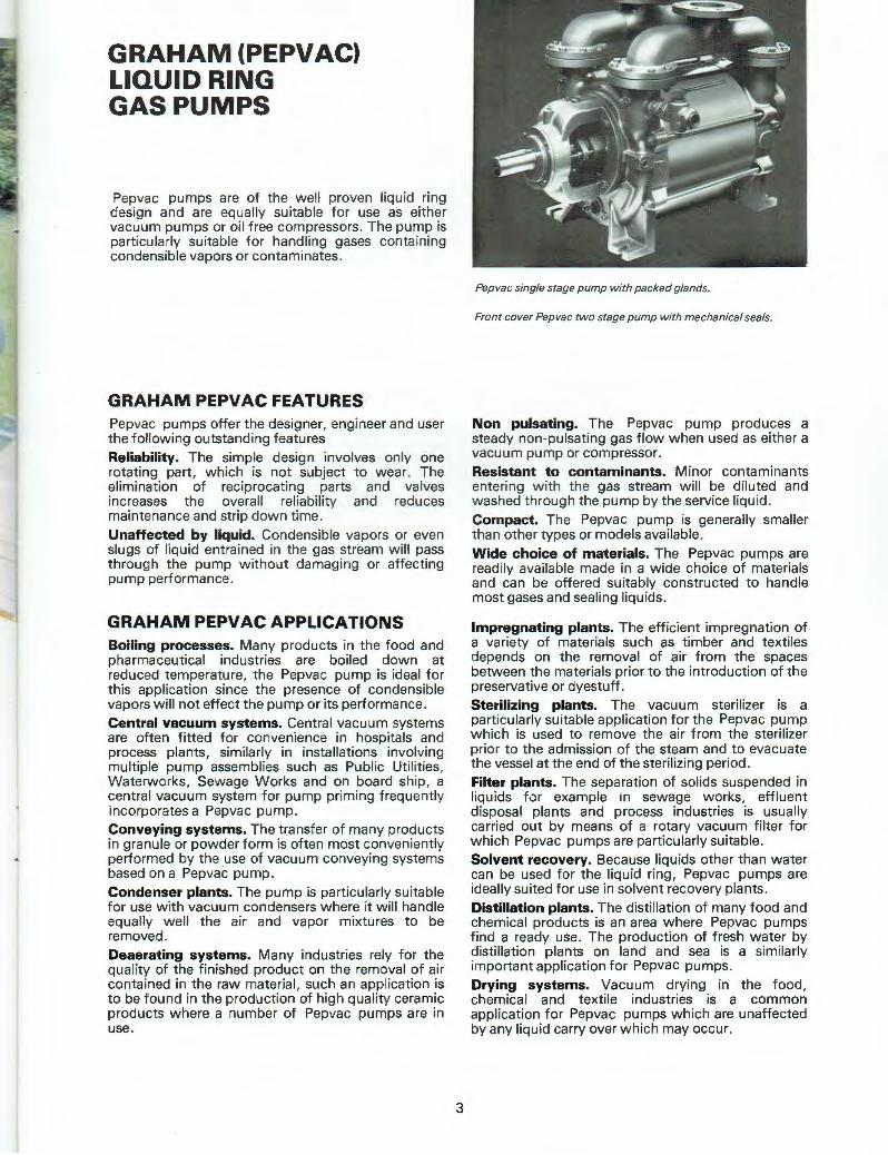
Pepvac single stage pump with packed glands.
Front cover Pepvac two stage pump with mechanical seals.
Non pulsating. The Pepvac pump produces a steady non-pulsating gas flow when used as either a vacuum pump or compressor. Resistant to contaminants. Minor contaminants enteri ng w ith the gas stream will be diluted and washed through the pump by the service liqu id. Compact. The Pepvac pump is generally smaller t han other types or models available. Wide choice of materials. The Pepvac pumps are read ily available made in a wide choice of materials and can be offered suitably constructed to handle most gases and sealing liquids.
Impregnating plants. The efficient impregnation of a variety of materials such as timber and text iles depends on the removal of air from the spaces between the materia ls prior to the introduction of the preservative or dyestuff . Sterilizing plants. The vacuum sterilizer is a particularly suitable application for the Pepvac pump which is used to remove the air from the sterilizer prior to the admission of the steam and to evacuate the vessel at the end of the sterilizing period . Filter plants. The separation of solids suspended in liquids for example in sewage works , effluent disposal plants and process industries is usually carried out by means of a rotary vacuum filter for which Pepvac pumps are particularly su itable. Solvent recovery. Because liquids other than water can be used for the liquid ring, Pepvac pumps are ideally suited for use in solvent recovery plants . Distillation plants. The dist illation of many food and chemical products is an area where Pepvac pumps find a ready use. The production of fresh water by distillation plants on land and sea is a similarly important application for Pepvac pumps. Drying systems. Vacuum drying in the food, chemical and textile industries is a common application for Pepvac pumps which are unaffected by any liquid carry over which may occur.
CONSTRUCTION
The Pepvac pump is of a rugged simple construction with the minimum of rotating parts, the design however incorporates major improvements over other types of liquid ring pump available.
Shafts. The shaft is considerably shorter and larger in diameter than those fitted to other makes. This is an important feature since failures of liquid ring pumps when they occur are generally associated w ith shaft damage arising through incorrect operation which sets up lateral vibrations in the rotating element . The provision of "oversize" shafts of shortened length reduces the risk of this type of damage.
TYPES AVAILABLE
Pepvac Single stage pumps capable of producing medium vacuum down to 90 Torr (26·4 inches Hg. vac .)
Pepvac Two stage pumps designed to operate in the higher industrial vacuum range down to 25 Torr (29 inches Hg . vac.)
Pepvac Two stage pumps with atmospheric air operated ejector staging for vacuua down to 2 Torr .
Pepvac Single Two stage compressors for pressures up to 2 bar (30 psig.)
SERIES 2 PUMPS
Mechanical seals. Pepvac pumps can be supplied as standard with mechanical sea ls. This feature eliminates shaft wear and overcomes a potential source of air leakage. In the case of the standard pump fitted with single seals it is not necessary to provide an additiona l external supply of gland flushing liquid since provision is made internally in the pump itself for a liquid flush to pass over the seal faces at all times when the pump is operating. For special applications double mechanical seals can be fitted . In these applications connections for the supply of external flushing liqu id are provided. Pumps with single or double packed glands can be supplied to special order if required.
PACKED GLANDS
The Series 1 pump is produced as standard with packed glands and well spaced outboard bearings. This series of pumps continues to be available in response to those users wishing to extend plants already incorporating Series 1 pumps and for engineers who have a preference for packed glands. Single and double seals in various configurations can also be supplied in this design if the end user wishes it. Drive. The Pepvac pump is equally suitable for either direct coupling to electric motors or for belt driving, optimum performance is based on operating at synchronous electric motor speeds.
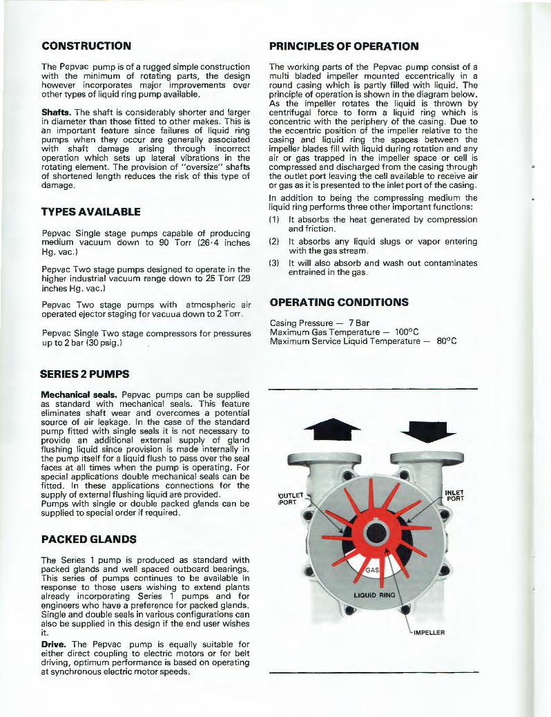
PRINCIPLES OF OPERATION
The working parts of the Pepvac pump consist of a multi bladed impeller mounted eccentrically in a round casing which is partly filled with liquid. The principle of operation is shown in the diagram below. As the impeller rotates the liquid is thrown by centrifugal force to form a liquid ring which is concentric with the periphery of the casing. Due to the eccentric position of the impeller relative to the casing and liquid ring the spaces between the impeller blades fill with liquid during rotation and any air or gas trapped in the impeller space or cell is compressed and discharged from the casing through the outlet port leaving the cell available to receive air or gas as it is presented to the inlet port of the casing.
In addition to being the compressing medium the liquid ring performs three other important functions:
( 1) It absorbs the heat generated by compression and friction.
(2) It absorbs any liquid slugs or vapor entering w ith the gas stream.
(3) It will also absorb and wash out contaminates entrained in the gas.
OPERATING CONDITIONS
Casing Pressure - 7 Bar Maximum Gas Temperature - 100°C Maximum Service Liquid Temperature - 80°C
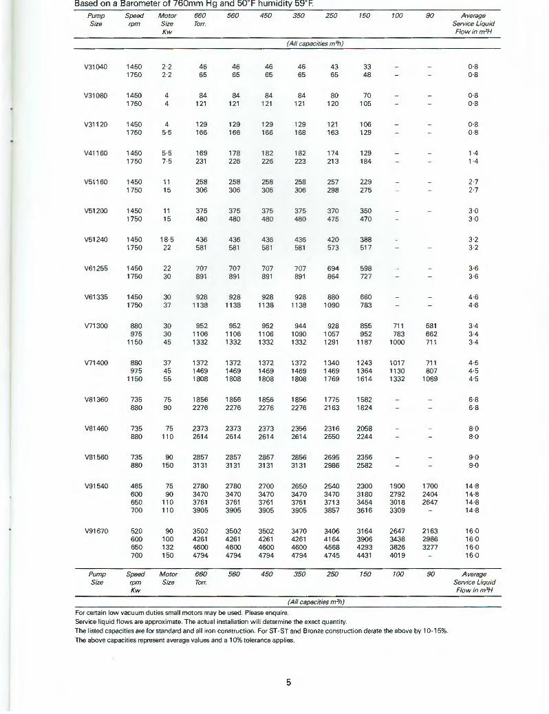
Based on a Barometer of 760mm Hg and 50°F humidity 59°F Pump Speed M otor 660 560 450 350 250 150 100 90 Average Size rpm Size Torr. Service Liquid
Kw Flow inm 3H
(All capacities m 3h}
V31040 1450 2·2 46 46 46 46 43 33 - - 08 1750 2·2 65 65 65 65 65 48 - - 08
V31080 1450 4 84 84 84 84 80 70 - - 0·8 1750 4 121 121 121 121 120 105 0·8
V31120 1450 4 129 129 129 129 121 106 - - 0·8 1750 5·5 166 166 166 168 163 129 - 0·8
V41160 1450 5·5 169 178 182 182 174 129 - - 1 A 1750 7·5 231 226 226 223 213 184 - 1-4
V51160 1450 11 258 258 258 258 257 229 - 27 1750 15 306 306 306 306 298 275 - - 27
V51200 1450 11 375 375 375 375 370 350 - 3·0 1750 15 480 480 480 480 475 470 - - 3·0
V51240 1450 18·5 436 436 436 436 420 388 - - 3·2 1750 22 581 581 581 581 573 51 7 - - 3·2
V61255 1450 22 707 707 707 707 694 598 - 3·6 1750 30 891 891 891 891 864 727 3·6
V61335 1450 30 928 928 928 928 880 660 - 4·6 1750 37 11 38 1138 1138 1138 1090 783 - 4·6
V71300 880 30 952 952 952 944 928 855 711 581 3-4 975 30 1106 1106 1106 1090 1057 952 783 662 3-4
1150 45 1332 1332 1332 1332 1291 1187 1000 711 3-4
V71400 880 37 1372 1372 1372 1372 1340 1243 1017 711 4·5 975 45 1469 1469 1469 1469 1469 1364 1130 807 4·5
1150 55 1808 1808 1808 1808 1769 1614 1332 1089 4·5
V81360 735 75 1856 1856 1856 1856 1775 1582 6·8 880 90 2276 2276 2276 2276 2163 1824 6·8
V81460 735 75 2373 2373 2373 2356 2316 2058 - - 8·0 880 110 2614 2614 2614 2614 2550 2244 - - 8·0
V81560 735 90 2857 2857 2857 2856 2695 2356 - - 9·0 880 150 3131 3131 3131 3131 2986 2582 - - 9·0
V91540 465 75 2780 2780 2700 2650 2540 2300 1900 1700 14·8 600 90 3470 3470 3470 3470 3470 3180 2792 2404 14·8 650 110 3761 3761 3761 3761 3713 3454 3018 2647 14·8 700 110 3905 3905 3905 3905 3857 3616 3309 - 14·8
V91670 520 90 3502 3502 3502 3470 3406 3164 2647 2163 16·0 600 100 4261 4261 4261 4261 4164 3906 3438 2986 16·0 650 132 4600 4600 4600 4600 4568 4293 3826 3277 16·0 700 150 4794 4794 4794 4794 4745 4431 4019 16·0
Pump Speed Motor 660 560 450 350 250 150 100 90 Average Size rpm Size Torr. Service Liquid
Kw Flowinm3H
(All capacities m 3h)
For certain low vacuum duties small motors may be used. Please enquire. Service liquid flows are approximate. The actual installation will determine the exact quantity. The listed capacities are for standard and all iron construction. For ST-ST and Bronze construction derate the above by 10-15%. The above capacities represent average values and a 10% tolerance applies.
5
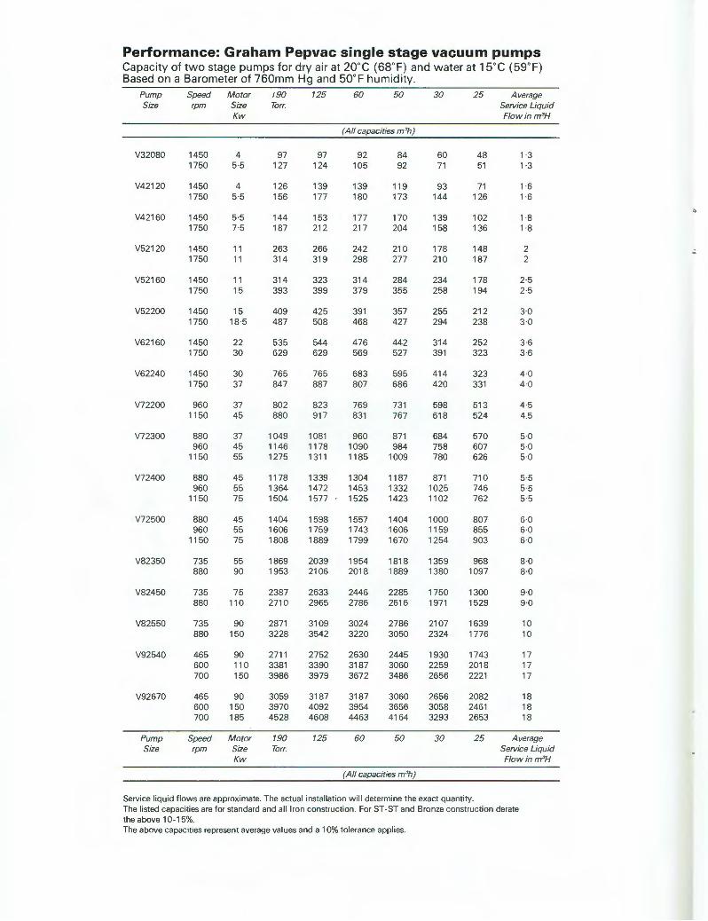
Performance: Graham Pepvac single stage vacuum pumps Capacity of two stage pumps for dry air at 20°C (68°F) and water at 15°C (59°F) Based on a Barometer of 760mm Hg and 50°F humidity.
Pump Speed Motor !90 125 60 50 30 25 Average Size rpm Size Torr. Service Liquid
Kw Flowinm 3H
(All capacities m 3h)
V32080 1450 4 97 97 92 84 60 48 1 3 1750 5·5 127 124 105 92 71 51 1 ·3
V42120 1450 4 126 139 139 119 93 71 1 ·6 1750 55 156 177 180 173 144 126 1 ·6
V42160 1450 55 144 153 177 170 139 102 1 8 1750 7·5 187 212 217 204 158 136 1 8
V52120 1450 11 263 266 242 210 178 148 2 1750 11 314 319 298 277 210 187 2
V52160 1450 11 314 323 314 284 234 178 2·5 1750 15 393 399 379 355 258 194 25
V52200 1450 15 409 425 391 357 255 212 3·0 1750 18 5 487 508 468 427 294 238 3·0
V62160 1450 22 535 544 476 442 314 252 3·6 1750 30 629 629 569 527 391 323 36
V62240 1450 30 765 765 683 595 414 323 40 1750 37 847 887 807 686 420 331 40
V72200 960 37 802 823 769 731 598 513 4·5 1150 45 880 917 831 767 618 524 4.5
V72300 880 37 1049 1081 960 871 684 570 5·0 960 45 11 46 1178 1090 984 758 607 50
1150 55 1275 1311 1185 1009 780 626 50
V72400 880 45 11 78 1339 1304 1187 87 1 710 5 5 960 55 1364 1472 1453 1332 1025 746 55
1150 75 1504 1577 1525 1423 1102 762 5·5
V72500 880 45 1404 1598 1557 1404 1000 807 60 960 55 1606 1759 1743 1606 1159 855 60
11 50 75 1808 1889 1799 1670 1254 903 6·0
V82350 735 55 1869 2039 1954 1818 1359 968 80 880 90 1953 2106 2018 1889 1380 1097 80
V82450 735 75 2387 2633 2446 2285 1750 1300 90 880 110 2710 2965 2786 2616 1971 1529 90
V82550 735 90 2871 3109 3024 2786 2107 1639 10 880 150 3228 3542 3220 3050 2324 1776 10
V92540 465 90 2711 2752 2630 2445 1930 1743 17 600 110 3381 3390 3187 3060 2259 2018 17 700 150 3986 3979 3672 3486 2656 2221 17
V92670 465 90 3059 3187 3187 3060 2656 2082 18 600 150 3970 4092 3954 3656 3058 2461 18 700 185 4528 4608 4463 4164 3293 2653 18
Pump Speed Motor 190 725 60 50 30 25 Average Size rpm Size Torr. Service Liquid
Kw Flowinm 3H
(All capacities m 3h)
Service liquid flows are approximate. The actual instal lation wi ll determine the exact quantity The listed capacities are for standa rd and all Iron construction. For ST-ST and Bronze construction derate the above 10-15%. The above capacities represent average values and a 10% to lerance applies.
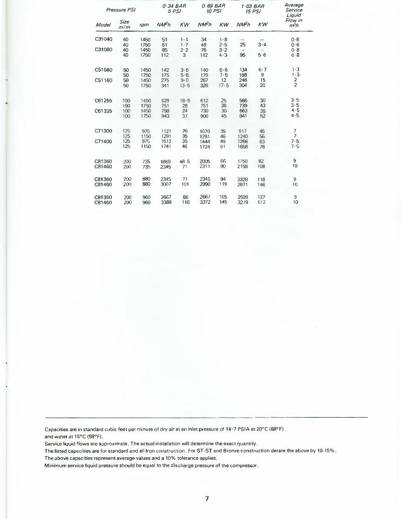
Pressure PSI 0 34 BAR 0 ·69 BAR 1 ·03 BAR
5 PSI 10 PSI 15 PSI
Size Model m ! m rpm NM3h KW NM3h KW NM3h KW
C31040 40 1450 51 1·1 34 1 ·8 -40 1750 61 1· 7 49 2·5 25 3·4
C31080 40 1450 85 2 ·2 76 3·2 - -40 1750 112 3 112 4·3 95 5·6
C51080 50 1450 142 3·5 140 5 ·6 134 6·7 50 1750 175 5·8 175 7·5 168 9
C51160 50 1450 275 9·0 267 12 246 15 50 1750 341 13· 5 326 17 · 5 304 20
C61255 100 1450 629 18 · 5 612 25 586 30 100 1750 751 28 751 36 739 43
C61335 100 1450 798 24 730 30 663 35 100 1750 943 37 900 45 841 52
C71300 125 975 11 21 26 1070 35 917 45 125 1150 1291 35 1291 46 1240 56
C71400 125 975 1512 35 1444 49 1266 63 125 1150 1741 46 1724 61 1658 78
C81360 200 735 1869 48 ·5 2005 66 1750 82 C81460 200 735 2345 71 2311 90 2158 108
C81360 200 880 2345 71 2345 94 2328 118 C81460 200 880 3007 101 2990 119 2871 146
C81360 200 960 2667 86 2667 105 2599 127 C81460 200 960 3389 11 8 3372 145 3279 172
Capacities are in standard cubic feet per minute of dry air at an inlet pressure of 14· 7 PS IA at 20° C 168° FI
and water at 15° C 159°Fi .
Service liquid flows are approximate . T he actual instaliation will determine the exa ct quantity .
Average Service Liquid Flow in
rri3h
0·6 0 · 6 0 ·8 0·8
1 ·3 1 ·3 2 2
3·5 3 · 5 4·5 4·5
7 7
7· 5 7· 5
9 10
9 10
9 10
The listed capacities are for standard and all Iron construction . For ST -ST and Bronze construction derate the above by 10-15%.
The above capac it ies represen t average values and a 10% to lera nce applies.
M inimum service liquid pressure shou ld be equal to the discharge pressure of the compressor.
7
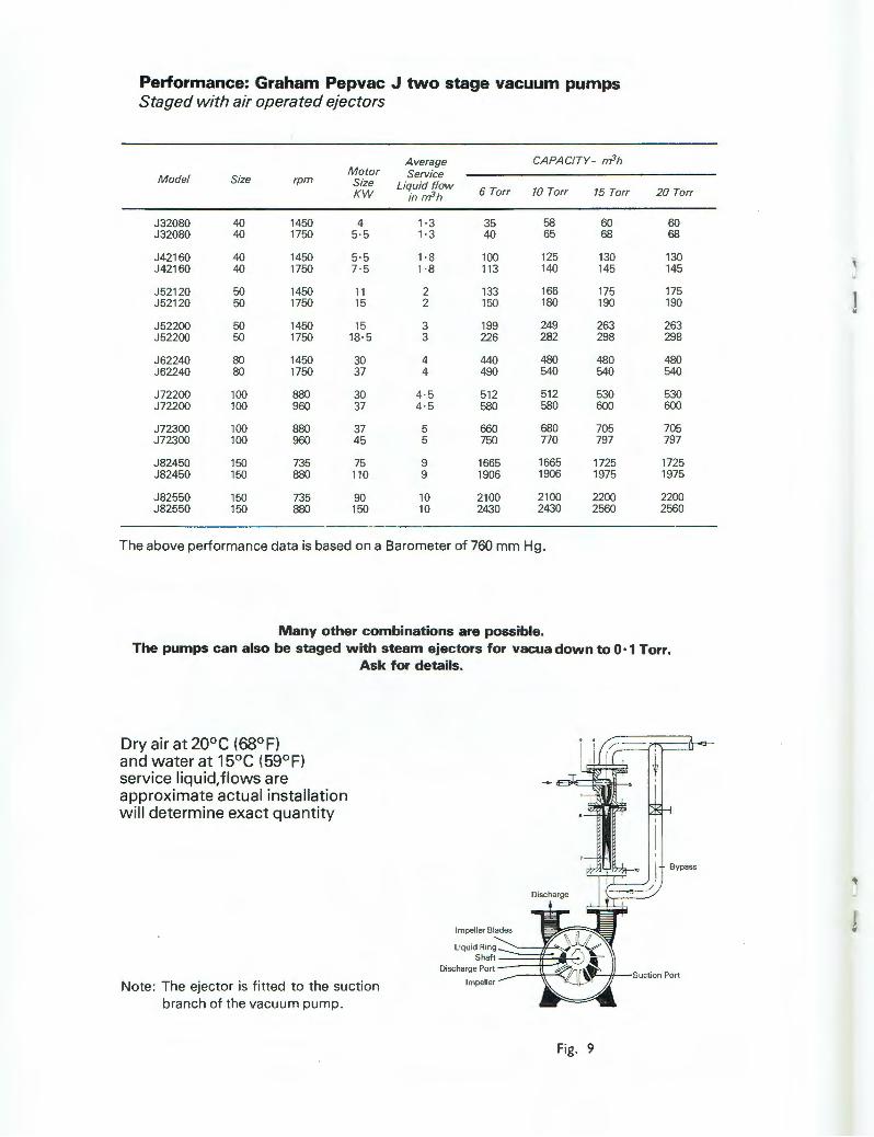
Performance: Graham Pepvac J two stage vacuum pumps Staged with air operated ejectors
Average CAPACITY- m3h Motor Service Model Size rpm Size Liquid flow KW in m3h 6 Torr 70 Torr 15 Torr 20 Torr
J32080 40 1450 4 1 ·3 35 58 60 60 J32080 40 1750 5·5 1 ·3 40 65 68 68
J42160 40 1450 5·5 1 ·8 100 125 130 130 J42160 40 1750 7 · 5 1 ·8 113 140 145 145
J52120 50 1450 11 2 133 166 175 175 J52120 50 1750 15 2 150 180 190 190
J52200 50 1450 15 3 199 249 263 263 J52200 50 1750 18·5 3 226 282 298 298
J62240 80 1450 30 4 440 480 480 480 J62240 80 1750 37 4 490 540 540 540
J72200 100 880 30 4·5 512 512 530 530 J72200 100 960 37 4 ·5 580 580 600 600
J72300 100 880 37 5 660 680 705 705 J72300 100 960 45 5 750 770 797 797
J82450 150 735 75 9 1665 1665 1725 1725 J82450 150 880 110 9 1906 1906 1975 1975
J82550 150 735 90 10 2100 2100 2200 2200 J82550 150 880 150 10 2430 2430 2560 2560
The above performance data is based on a Barometer of 760 mm Hg .
Many other combinations are possible. The pumps can also be staged with steam ejectors for vacua down to 0· 1 Torr.
Dry air at 20° C (68° F) and water at 15° C (59° F) service liquid, flows are approximate actual installation will determine exact quantity
Ask for details.
Note : The ejector is f itted to the su ct ion branch of the vacuum pump .
Fig. 9
' J
j
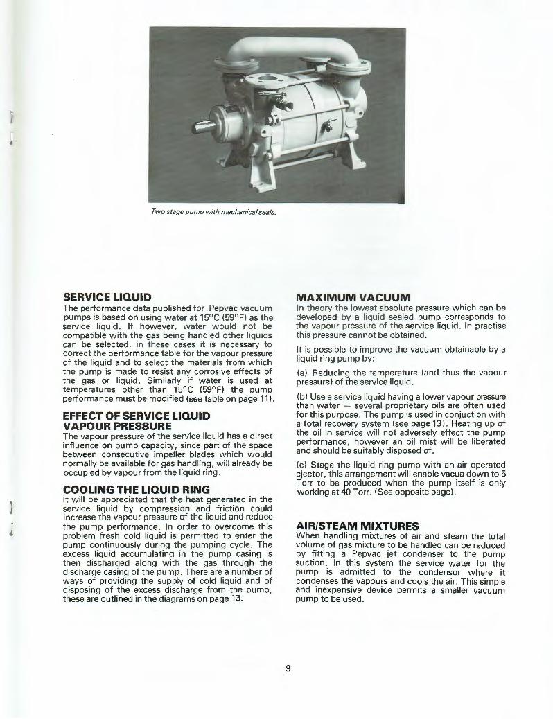
Two stage pump with mechanical seals.
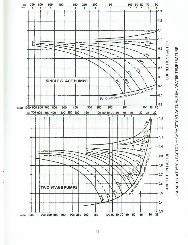
SERVICE LIQUID The performance data published for Pepvac vacu um pumps is based on using water at 15° C (59° F) as the service liquid. If how ever, w ater wou ld not be compatib le w ith t he gas being handled other liquids can be selected , in these cases it is necessary to correct the performance table f or the vapour pressure of the liquid and to select the materials from which the pump is made to resist any corrosive effects of the gas or liquid. Similarly if water is used at temperatures other than 15°C (59°F) the pump performance must be modified (see table on page 11) .
EFFECT OF SERVICE LIQUID VAPOUR PRESSURE The vapou r pressure of t he service liqu id has a direct infl uence on pump capaci ty , since part of the space between consecutive impeller blades which wou.ld normally be available for gas handl ing, wil l already be occupied by vapour from the liquid ring.
COOLING THE LIQUID RING It will be appreciated that the heat generated in the service liquid by compression and friction could increase the vapour pressure of the liquid and reduce the pump performance . In order to overcome this problem fresh cold liquid is permitted to enter the pump continuously during t he pumping cycle. The excess liquid accumulating in the pump casing is then discharged along with the gas through the discharge casing of the pump . There are a number of ways of providing the supply of cold liquid and of disposing of the excess discharge from the oump, these are outlined in the diagrams on page 13.
9
MAXIMUM VACUUM In theory t he lowest absolute pressure which can be developed by a liquid sea led pump corresponds to the vapour pressure of the service liqu id . In practise th is pressu re cannot be obtained .
It is possible to improve the vacuum obtainable by a liquid ring pump by :
(a) Reducing the temperature (and thus the vapour pressure) of the service liquid .
(b) Use a service liqu id having a lower vapour pressure than water - several proprietary oils are of ten used for this purpose . The pump is used in conjuction w ith a t ota l recovery system (see page 13) . Heating up of the oil in service wi ll not adversely effect the pump performance, however an oi l mist will be liberated and should be su itably disposed of .
(c) Stage the liquid ring pump with an air operated ejector, this arrangement will enable vacua down to 5 Torr to be produced when the pump itself is only working at 40 Torr. (See opposite page).
AIR/STEAM MIXTURES When handling mixtures of air and steam the total volume of gas mixture to be handled can be reduced by fitting a Pepvac jet condenser to the pump suction. In this system the service water for the pump is admitted to the condensor where it condenses the vapours and cools the air. This simple and inexpensive device permits a smaller vacuum pump to be used.
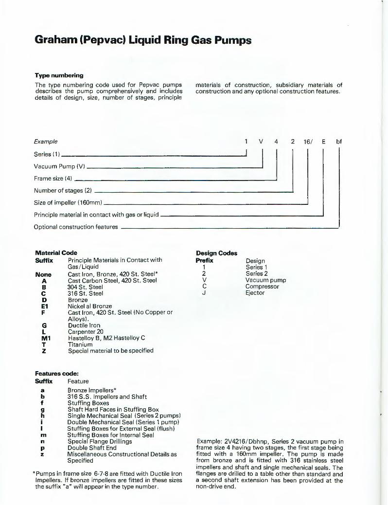
Graham {Pepvac) Liquid Ring Gas Pumps
Type numbering
The type numbering code used for Pepvac pumps describes the pump comprehensively and includes details of design, size , number of stages, principle
Example
materials of construction, subsidiary materials of construction and any optional construction features.
v 4 2 16/ E bf
Series (1) -------------------------Vacuum Pump (V) ______________________ __.
Frame size (4) --------------------------~
Number of stages (2) -------------------------____.
Size of impeller ( 160mm) --------------------------___,
Principle material in contact with gas or liquid -------------------------'
Optional construction features -----------------------------
Material Code Suffix Principle Materials in Contact with
None A B c D E1 F
G L M1 T z
Gas / Liquid Cast Iron, Bronze, 420 St. Steel * Cast Carbon Steel, 420 St. Steel 304 St. Steel 316 St. Steel Bronze Nickel al Bronze Cast Iron, 420 St. Steel (No Copper or Alloys). Ductile Iron Carpenter 20 Hastelloy B, M2 Hastelloy C Titanium Special material to be specified
Features code: Suffix Feature
a Bronze Impellers* b 316 S.S . Impellers and Shaft f Stuffing Boxes g Shaft Hard Faces in Stuffing Box h Single Mechanical Seal (Series 2 pumps)
Double Mechanical Seal (Series 1 pump) Stuffing Boxes for External Seal (flush)
m Stuffing Boxes for Internal Seal n Special Flange Drillings p Double Shaft End z Miscellaneous Constructional Details as
Specified
* Pumps in frame size 6-7-8 are fitted with Ductile Iron Impellers. If bronze impellers are fitted in these sizes the suffix " a" will appear in the type number.
Design Codes Prefix
1 2 v c J
Design Series 1 Series 2 Vacuum pump Compressor Ejector
Example : 2V4216/ Dbhnp, Series 2 vacuum pump in frame size 4 having two stages, the first stage being fitted with a 160mm impeller. The pump is made from bronze and is fitted with 316 stainless steel impellers and shaft and single mechanical seals. The flanges are drilled to a table other than standard and a second shaft extension has been provided at the non-drive end.
Torr 700 600 500 400 300 250 200 150 100 90 80 70 60
1,3
1,2
'\Ooc ,__ ., ----r-~
1,1
15°C
l - ------.-- 17° C -- - - .L c: - -- - -- --- ·- -.._ .__
r---- -- ::--::.. -- ----- -- ~~ -- -. ~ --~- ----- --....; - --r--.... - .. ~ - ....... I ......... ---- - ~ ~ -... ......... .... "" ',<>~C' -.......... ....
. ~ .... , ~ '" ".... ....... ..... ' ..... ' .....
,_ '
"" '', ' ~ '\ ~ 'f
..... '· (> " " SINGLE STAGE PUMPS ~ ,,~o \
\ \ 0 \ (>
'· (> ~ .. ~
\~:Y \ \' .\' · contact G·
. in tnis area _,__ For Op~rat1on I I
1,0 c:: 0
0,9 I-u <{ u...
0,8 z 0 I-
0,7 u UJ c:: c::
0,6 0 u
0,5
0,4
mbar 1000 900 800 700 600
Torr 700 600 500 400
500 400
300 250 200
300
150
250 200 150
100 90 80 70 60 50 40
0,3 100 90 80
30 25 20
m bar 1000
TI rrr
t)' "
[/'.,c../ l/ ""}.."
- '\'?>o~ i.--"' - ~1;1 '--- .-- --~
~~AoC -- -- -- - 15°C --- - . -· -- -- --- 76oc Q - ...... -- -- -- ~ - =-=:.i.- ---- -1 Q . ·-- i--- --::::::- -- ....... ._- -1 .... ......._""-- leo c.::;" -- - - ~ ... _ - - ............. ~ - ........ -.................... ........ I' C' ;..., - i-
,.._r--r--- ....... r---..... i....., ~~ .... r-.....' CJ ..... r--..... ' ""1-...?oo /J r--....._ ....... r--... .. • ~ .. r-... '" '2 ,c 0
.................... ,,
" ' ' .., -:.?o- CJ -
~'"~ ~ ~ ' " ', .. 9 o 4...:
'" t\.. ' .:>~ 0 . "'ro
' "' '· "'\. ' Vl 0 "
• "'R~o (> s \ (> (> ·$"
' '& \ . Qc::-
TWO STAG E PUMPS \ \ \\ ~ ,0 t0 ~ rt-
~ I , Q~ ~ ~~ 0 o'"""
'ho \(I L/~ <(
(\ · ~ ~
i...-----
1,3
1,2
1,1
1,0
c:: 0,9 ~
u <{
0,8 u... z 0
0,7 I-u UJ c:: 0,6 c:: 0 u
0,5
0,4
700 600 500 400 300 250 200 150 100 90 80 70 60 50 40 0,3
30 25
11
UJ c:: ::::> 1-<i:: c:: UJ Cl... ~ UJ IC: UJ 1-<i:: s _J
<{ UJ (/) _J
<{ ::::> 1-u <{
1-<i:: >-1-u <{ Cl... <{ u II
c:: 0 1-u <{ u... x u 0 i.!) ....... 1-<i:: >-1-u <{ Cl... <{ u
75
74
73
72
E :i :i
~ 70 cii
I
E u E :i :i u
"' > Cl c:
:_;;;; 0 s
68
65
60
50
40
30
20
10
0
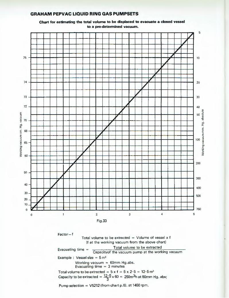
GRAHAM PEPVAC LIQUID RING GAS PUMPSETS
-
-
-
-
-
- ~ 'I
0
Chart for estimating the total volume to be displaced to evacuate a closed vessel to a pre-determined vacuum.
/ l/
I/
~
~ /
~, ,
Factor-f
7 , ~ ,
/ ~ ,
/i v
v ~
~ II"
~ ~
~' / ~ ,
v 7
~' /
2
Fig.33
3 4
Total volume to be extracted = Volume of vessel x f (f at the working vacuum from the above chart)
Total volume to be extracted
/ ~ ..
7
Evacuating time = Capacitvof the vacuum pump at the working vacuum
Example : Vessel size = 5 m3
Working vacuum = 60mm Hg.abs. Evacuating time = 3 minutes
Totalvolumetobeextracted = 5xf = 5x2·5 = 12·5m3
Capacity to be extracted = 123 5 x 60 = 250m3h at 60mm Hg . abs;
Pump selection = V5212 (from chart p.6). at 1450 rpm.
/
5
5
10
20
30
40 ~ :i
50 0 "' .0
"' Cl I
E E E :i
100 13
200
300
400
500
760
"' > Cl c:
:_;;;; 0 s
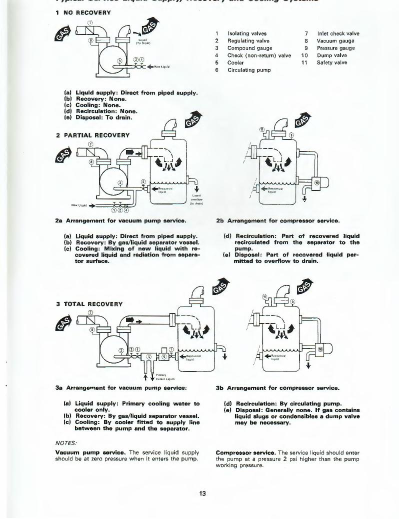
.,,., ...................... "' ..... _ . .., ............. ,..,...,, .. -.................. , .... _ ---····.:;, -,---···-1 NO RECOVERY
" ~' L iciu1d ( To Drain)
+ New l iquid
(a) Liquid supply: Direct from piped supply. (b) Recovery: None. (c) Cooling: None. (d) Recirculation: None. -1J!!t (e) Disposal: To drain. ........, ~
2 PARTIAL RECOVERY
" CD®©
2a Arrangement for vacuum pump service.
(a) Liquid supply: Direct from piped supply. (b) Recovery: By gas/liquid separator vessel. (c) Cooling: Mixing of new liquid with re-
covered liquid and radiation from separator surface.
3 TOTAL RECOVERY
-- ...... ,
" -- \ ~l__J#
J~\i.
t . l .p,;m"y T Cooler Liquid
3a Arrangement for vacuum pump service;
(a) Liquid supply: Primary cooling water to cooler only.
(b) Recovery: By gas/liquid separator vessel. (c) Cooling: By cooler fitted to supply line
between the pump and the separator.
NOTES:
Vacuum pump service. The service liquid supply should be at zero pressure when it enters the pump.
13
1 Isolating valves 7 Inlet check valve 2 Regulating valve 8 Vacuum gauge 3 Compound gauge 9 Pressure gauge 4 Check (non-return) valve 10 Dump valve
5 Cooler 11 Safety valve 6 Circulating pump
~
2b Arrangement for compressor service.
(d) Recirculation: Part of recovered liquid recirculated from the separator to the pump.
(e) Disposal: Part of recovered liquid permitted to overflow to drain. ,
~ ~
3b Arrangement for compressor service.
(d) Recirculation: By circulating pump. (e) Disposal: Generally none. If gas contains
liquid slugs or condensibles a dump valve may be necessary.
Compressor service. The service liquid should enter the pump at a pressure 2 psi higher than the pump working pressu re.
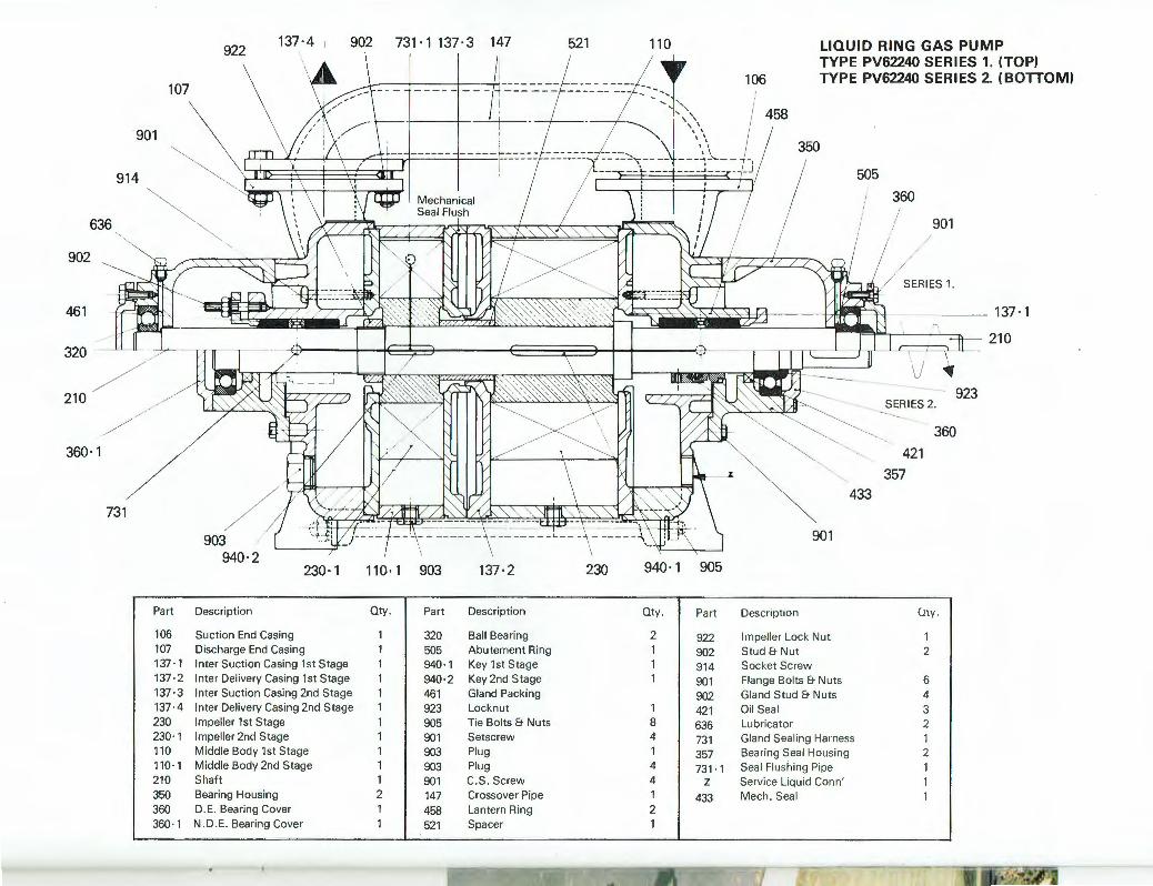
636
902
461
360· 1
922 137 ·4 I 902 731· 1137·3 147
107 __...~~--t-~~--j~~-rt--- -----
901
914
"
521
458
LIQUID RING GAS PUMP TYPE PV62240 SERIES 1. (TOPI TYPE PV62240 SERIES 2. (BOTTOM)
505
360
901
SERIES 1.
~ '~f~~ · ' · ( . ' ·. " v ' ' ' · , · '" , , · , · ~ (~ /;; { S I~ >k ~~~·~'~>,'),'~;,fu~ ?f' ) ) :)£1 -~ I ", -- 137·1 ' I :::J>-- 21 0
433
421 357
360
731
Part
106 107 137· 1 137 ·2 137·3 137·4 230 230·1 110 110· 1 210 350 360 360·1
903 940·2
Descript ion
Suction End Casing
230 · 1
Discharge End Casing Inter Suction Casing 1st Stage Inter Delivery Casing 1st Stage Inter Suction Casing 2nd Stage Inter Delivery Casing 2nd Stage Impeller 1st Stage Impeller 2nd Stage Middle Body 1st Stage Middle Body 2nd Stage Shaft Bearing Housing D.E. Bearing Cover N.D .E. Bearing Cover
110· 1 903 137 ·2
Oty. Part Description
1 320 Ball Bearing 1 505 Abutement Ring 1 940 ·1 Key 1st Stage 1 940·2 Key 2nd Stage 1 461 Gland Packing 1 923 Locknut 1 905 Tie Bolts & Nuts 1 901 Setscrew 1 903 Plug 1 903 Plug 1 901 C.S. Screw 2 147 Crossover Pipe 1 458 Lantern Ri ng 1 521 Spacer
901
230 940· 1 905
Oty. Part Description C.!ly .
2 922 Impeller Lock Nut 1 1 902 Stud & Nut 2 1 914 Socket Screw 1 901 Flange Bolts & Nuts 6
902 Gland Stud & Nuts 4 1 421 Oil Seal 3 8 636 Lubricator 2 4 731 Gland Sealing Harness 1 1 357 Bearing Sea l Housing 2 4 731· 1 Sea l Flushing Pipe 1 4 z Service Liquid Conn' 1 1 433 Mech. Seal 1 2 1
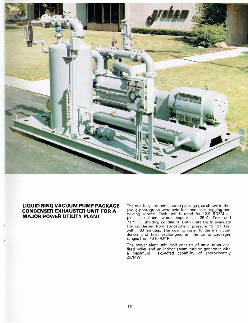
LIQUID RING VACUUM PUMP PACKAGE CONDENSER EXHAUSTER UNIT FOR A MAJOR POWER UTILITY PLANT
The two fully automatic pump packages, as shown in the above photograph were sold for condenser hogging and holding service. Each unit is rated for 12.5 SCFM air plus associated water vapour at 25·4 Torr and 71 ·5° F. (holding condition). Both units are to evacuate the condenser from atmostpheric pressure to 127 Torr within 60 minutes. The cooling water to the main condenser and heat exchangers on the pump packages ranges from 40 to 90° F.
The power plant unit itself consists of an outdoor coal fired boiler and an indoor steam turbine generator with a maximum expected capability of approximately 267MW
15

PV1 /2 0792
The Best of British
Graham Precision Pumps Limited The Forge, Congleton, Cheshire, CW12 4HQ, England. Telephone. 0260 274721. Telex . 667383. Fax.0260 276965