![COMBINATION CAMERA TK-C675B - JVCpro.jvc.com/pro/attributes/cctv/manual/tkc675bu.pdf · exigences du Réglement sur le matériel brouilleur du Canada. This Class [B] digital apparatus](https://static.fdocuments.in/doc/165x107/5edfd7eaad6a402d666b245f/combination-camera-tk-c675b-exigences-du-rglement-sur-le-matriel-brouilleur.jpg)
COMBINATION CAMERA C-CC514 NT, C-CC514 PL C ... you for your purchasing TOA’s Combination Camera....
82
Thank you for your purchasing TOA’s Combination Camera. Please carefully follow the instructions in this manual to ensure long, trouble-free use of your equipment. COMBINATION CAMERA OUTDOOR COMBINATION CAMERA C-CC514 NT, C-CC514 PL C-CC564 NT, C-CC564 PL C-CC574 NT, C-CC574 PL C-CC714 NT, C-CC714 PL C-CC764 NT, C-CC764 PL C-CC774 NT, C-CC774 PL SETUP MANUAL
Transcript of COMBINATION CAMERA C-CC514 NT, C-CC514 PL C ... you for your purchasing TOA’s Combination Camera....

Thank you for your purchasing TOA’s Combination Camera. Please carefully follow the instructions inthis manual to ensure long, trouble-free use of your equipment.
COMBINATION CAMERA
OUTDOOR COMBINATIONCAMERA
C-CC514 NT, C-CC514 PLC-CC564 NT, C-CC564 PLC-CC574 NT, C-CC574 PLC-CC714 NT, C-CC714 PLC-CC764 NT, C-CC764 PLC-CC774 NT, C-CC774 PL
SETUP MANUAL

2
TABLE OF CONTENTS
1. SETTING ITEMS GUIDE ................................................................................ 5
2. BEFORE SETTING 2.1. Address Display When Turning Power On ................................. 82.2. Keys Used to Settings ................................................................ 82.3. Setting Basic Operation ............................................................. 9
3. ENTERING CAMERA MENU SCREEN3.1. Selecting the Language ............................................................ 10
4. SETTING PRESETS4.1. Entering Presets Into the Memory ............................................ 114.2. Global Preset Memory Correction ............................................ 134.3. Preset Memory Reset ............................................................... 144.4. Preset Memory All Reset .......................................................... 154.5. Automatic Return Setting ......................................................... 154.6. Home Setting ............................................................................ 164.7. Preset Memory Freeze Setting
(C-CC564, C-CC574, C-CC764 and C-CC774 only) ....................... 16
5. ID (TITLE) SETTINGS5.1. Setting Display Content ............................................................ 17
5.1.1. Setting display items ............................................................................ 185.2. ID Settings ................................................................................ 19
5.2.1. Camera ID setting ................................................................................ 195.2.2. Position ID setting ................................................................................ 195.2.3. Trace ID setting .................................................................................... 205.2.4. Auto Pan ID setting .............................................................................. 205.2.5. Tour ID setting ..................................................................................... 205.2.6. Home ID setting ................................................................................... 215.2.7. Alarm ID setting ................................................................................... 215.2.8. Sector ID setting .................................................................................. 215.2.9. AUX ID setting ..................................................................................... 23
5.3. Entering Title Characters .......................................................... 245.3.1. Understanding the ID Entry screen ...................................................... 245.3.2. Character entry basic operation ........................................................... 255.3.3. Erasing or correcting characters .......................................................... 255.3.4. Entering title using code ....................................................................... 265.3.5. ID code table ........................................................................................ 27
5.4. ID Display Position Settings ..................................................... 285.4.1. Setting the common title display position and its length ...................... 285.4.2. Initializing the common title display position ........................................ 30
5.5. Frame Adjustment Setting ........................................................ 305.6. Angle Origin Point (Zero point) Change ................................... 30

3
6. CAMERA CHARACTERISTICS SETTINGS .......................................... 316.1. Setting the White Balance ........................................................ 326.2. Setting the Backlight Compensation ........................................ 336.3. Adjusting the Brightness ........................................................... 346.4. Setting the Day and Night
(C-CC564, C-CC574, C-CC764 and C-CC774 only) ........................ 346.5. Setting the Auto Focus ............................................................. 356.6. Setting the AGC ....................................................................... 356.7. Setting the Slow Shutter (High Sensitivity) ................................... 366.8. Setting the Shutter Speed ........................................................ 366.9. Setting the Electronic Zoom ..................................................... 376.10. Setting the Enhancer Function ............................................... 376.11. Setting the Chroma ................................................................. 386.12. Changing the Synchronization System .................................. 386.13. Electronic Image Stabilization Settings
(C-CC574 and C-CC774 only) ................................ 396.14. Sensitivity-Up Settings (C-CC574 and C-CC774 only) ...................... 396.15. Initializing Camera Settings .................................................... 40
7. SETTING AUTOMATIC OPERATIONS ................................................... 407.1. Assigning the Function to the Auto Key ................................. 417.2. Auto Pan Function Setting ....................................................... 41
7.2.1. Setting Auto Pan option operations ..................................................... 417.2.2. Setting the Auto Pan stop duration at an endpoint ............................. 427.2.3. Auto Pan speed setting ....................................................................... 427.2.4. Setting the direction of Auto Pan rotation ........................................... 427.2.5. Setting or deleting the Auto Pan limits ................................................ 43
7.3. Setting the Sequence Function ............................................... 447.3.1. Setting the sequential order ................................................................ 447.3.2. Setting the interval of sequential playback duration ............................ 44
7.4. Trace Function Setting ........................................................... 457.4.1. Storing the Trace operation ................................................................ 45
7.5. Setting the Trace Pause Time 1 and 2 ..................................... 467.6. Tour Setting .............................................................................. 47
7.6.1. Tour programming ............................................................................... 477.6.2. Inserting operation into Tour program .................................................. 497.6.3. Deleting Tour program ......................................................................... 50
8. ALARM SETTINGS8.1. Input Setting ............................................................................. 518.2. Report Setting .......................................................................... 528.3. Active Level Setting .................................................................. 538.4. Priority Setting .......................................................................... 538.5. Operation (Action) Setting ........................................................ 548.6. Clock Setting ............................................................................ 558.7. Reset Operation (Action) Setting .............................................. 568.8. Verifying Alarm Logs (Alarm Data) .............................................. 57
4
9. CONTACT OUTPUT SETTINGS 9.1. AUX 1 Setting ........................................................................... 589.2. AUX 2 Setting (C-CC564 and C-CC574 only) ...................................... 59
10. TIMER SETTINGS 10.1. Program Settings .................................................................... 60
10.1.1. Erasing Timer program ...................................................................... 6210.2. Time Display Selection ........................................................... 6310.3. Date Display Setting ............................................................... 6310.4. Setting the Timer .................................................................... 6410.5. Setting the Date ...................................................................... 6410.6. Setting the Summer Time (Daylight saving time) ......................... 65
11. MANUAL SETTINGS11.1. Resetting Zoom Interlocking ................................................... 6611.2. Rotation Limit Selection .......................................................... 6611.3. Rotation Limit Setting ............................................................. 6711.4. Manual Speed Setting ............................................................ 6711.5. Setting the Flip Function
(C-CC564,C-CC574, C-CC764 and C-CC774 only) ........................ 6811.6. Resetting Tilt Angle Limits ...................................................... 69
12. MAINTENANCE SETTINGS12.1. Initializing ................................................................................ 7012.2. Refresh Function Settings ...................................................... 7112.3. Password Setting ................................................................... 7212.4. Motor Power Setting ............................................................... 7212.5. Return All Settings to Initial Status Set by the Factory ........... 7312.6. Automatic Correction (Auto Adjust) ............................................. 7312.7. Data Backup ........................................................................... 7412.8. Motion Detection Settings
(C-CC564,C-CC574, C-CC764 and C-CC774 only) ........................ 7412.8.1. Detection area setting ........................................................................ 7512.8.2. Action setting ..................................................................................... 76
12.9. Privacy Masking Settings(C-CC564,C-CC574, C-CC764 and C-CC774 only) ........................ 77
12.9.1. Setting the Privacy Masking .............................................................. 7712.9.2. Clearing the Privacy Masking ............................................................ 7912.9.3. Changing the masking patterns ......................................................... 79
13. CHANGING THE CAMERA SETTINGS FOR ARBITRARY POSITIONS
13.1. Entering the Camera Setting Screenfor Individual Camera Positions ........................... 80
13.2. Changing Position Picture Qualityand ID Display Positions ..................................... 81
13.2.1. Changing arbitrary position picture quality using the scene function .......................................... 81
13.2.2. Changing the ID display positionfor arbitrary camera position using the pattern function ...... 81

5
CAMERA MENU
PRESET (p.11)
MEMORY *1 (p.11)
READJUST ALL POS (p.13)
DISPLAY (p.17)
ID SETTING (p.19)
WHITE BALANCE *2 (p.32)
BACKLIGHT *2 (p.33)
BRIGHTNESS *2 (p.34)
DAY/ NIGHT *2 *3 (p.34)
ID SETTING (p.17)
CAMERA SETTING (p.31)
(p.10)
Setting Item
MAIN MENU
To next page
Programs the camera position (camera direction), displayssetting status, and performs reset.
Programs the camera position.
Corrects all preset camera positions.
Sets to display or hides the title.
Sets the title.
Sets ID.
Sets camera properties.
Sets the camera’s white balance.
Sets the backlight compensation.
Adjust the camera’s brightness.
Sets to give operation priority to black & white modeor slow shutter mode depending on the subject’sbrightness.
Sets Auto-Focus mode.
Sets AGC.
Sets slow shutter.
Sets shutter speed.
Sets a maximum enlargement of electronic zoom.
ENHANCER *2 (p.37)
CHROMA *2 (p.38)
SYNC (p.38)
Sets contour enhancement.
Switches sync. system and adjusts phase.
Adjusts the chroma.
MEMORY RESET (p.14) Resets preset camera position.
MEMORY ALL RESET (p.15) Resets all preset camera positions.
AUTO RETURN (p.15)The camera returns to the preset position auto-matically when the preset period of time elapses byexternal control.
HOME (p.16) Designates the program the camera automaticallyreturns to.
PRESET FREEZE *3 (p.16) Displays the still image during camera movementbetween preset positions.
LOCATION *2 (p.28) Sets title display position and its length.
FRAME ADJUST (p.30) Sets the character display position.
AUTO FOCUS (p.35)
AGC *2 (p.35)
SLOW SHUTTER *2 (p.36)
SHUTTER SPEED *2 (p.36)
E–ZOOM (p.37)
ZERO POINT (p.30) Sets the origin point of the angle display.
1. SETTING ITEMS GUIDE
The camera menu screens are comprised of the following setting item screens.

6
From previous page
AUTO KEY (p.41)
AUTO PAN (p.41)
SEQUENCE (p.44)
TRACE (p.45)
TOUR (p.47)
AUTO MODE (p.40) Sets automatic operation of Auto Pan, Preset sequence, Traceand Tour.
Assigns automatic function to the Auto key.
Sets the Auto Pan operations.
Sets the preset sequence order.
Stores trace movements.
Sets the operation to be programmed.
ALARM (p.51) Sets alarm operations.
AUX (p.58) Sets contact output.
TIMER (p.60) Sets the timer.
TRACE 1 PAUSE TIME (p.46) Sets the stop duration of trace movements.
TRACE 2 PAUSE TIME (p.46) Sets the stop duration of trace movements.
INPUT (p.51)
REPORT (p.52)
ACTIVE STATE (p.53)
PRIORITY (p.53)
RESET ACTION (p.56)
Sets input number of alarm input.
Sets the terminal that transmits the alarminformation.
Selects whether to activate the alarm input withmake or break contacts.
Sets whether to forcibly execute action or to setpriority order to operation.
Sets camera operation when the alarm conditionsare released.
ACTION (p.54)Sets camera operation when alarm signal isreceived.
INTERVAL (p.55) Sets the period of time that alarm conditions aremaintained.
ALARM DATA (p.57) Verify alarm logs.
AUX1 (p.58) Sets contact output.
AUX2 *4 (p.59) Sets contact output.
PROGRAM (p.60)
ENTER TIME (p.64)
Sets predetermined operations to be performed atpreset times.
Sets the time.
TIME DISPLAY (p.63) Sets time display to 12-hour or 24-hour displayformats.
DATE DISPLAY (p.63) Sets date display.
ENTER DATE (p.64) Sets the date.
To next page
SUMMER TIME (p.65) Sets the summer time (Daylight saving time).
RESET (CAM SETTING) (p.40)Return each item on the camera setting screen tothe factory default status.
EIS *5 (p.39) Electronic Image Stabilization settings.
SENSITIVITY *5 (p.39) Sensitivity-Up selection.

7
*1 Setting for this item can be entered by the Main Menu screen not by the Camera Menu screen when theequipments other than the C-RM500 are connected.
*2 Can also be changed for individual positions at the Camera setting screen for individual positions.*3 Can be only set for the C-CC564, C-CC574, C-CC764 and C-CC774.*4 Can be only set for the C-CC564 and C-CC574.*5 Can be only set for the C-CC574 and C-CC774.
MANUAL (p.66) Individual settings.
ZOOM SCALABLE P/T (p.66)
MAX P/T SPEED (p.67)
Resets zoom interlocking.
Sets the maximum speed of pan and tilt operation.
P/T LIMIT (p.66) Designate the pan and tilt rotation limits.
P/T LIMIT SETTING (p.67) Sets the pan and tilt rotation limits.
FLIP (p.68) Sets whether to set the tilt rotation range to 90 orover.
UP LIMIT (p.69) Sets the tilt angle limit.
From previous page
INITIALIZE (p.70)
REFRESH (p.71)
PASSWORD (p.72)
MOTOR POWER (p.72)
DATA BACKUP (p.74)
MAINTENANCE (p.70) Sets functions during maintenance.
LANGUAGE (p.10) Selecting the language.
Corrects deviation of stepping motor.
Corrects deviation of position.
Sets the password required when activatingmaintenance menu screen.
Improves deviation of preset position.
Sets data writing and reading.
FACTORY PRESET (p.73) Returns all setting to initial status set by the factory.
AUTO ADJUST (p.73) Automatically corrects deviation of position.
MOTION DETECTION *3 (p.74)
PRIVACY MASK *3 (p.77)
Sets motion detection.
Sets privacy masking area.
NoteThe name of article of the text is displayed as follows;
C-CC514: C-CC514 NT or C-CC514 PLC-CC564: C-CC564 NT or C-CC564 PLC-CC574: C-CC574 NT or C-CC574 PLC-CC714: C-CC714 NT or C-CC714 PLC-CC764: C-CC764 NT or C-CC764 PLC-CC774: C-CC774 NT or C-CC774 PL

8
C A M E R A A D D R E S S
- N T S C
3 8 4 0 0 B P S* * * * * - * * * * *
* * *
X X X X X X X O X X X X X X X X X O X X
Camera address screen
P
A B C D
WIPER
ZOOMTELE
WIDE
FOCUSFAR
NEAR
LENS SPEEDUP
DOWN
RIGHTLEFT
LOW HIGH
DEF AUX AUTO
E F G H SELECT MENUGROUP
CHSEQUENCEF U N C T I O N
A L A R M
RESET HOLD
AF POSITION CONTROLFREEZE FULL
REMOTE CONTROLLER C-RM500
1 2 3
4 5 6
7 8 9
C 0 SET
Joystick Clear keyFocus keyZoom key Set key
Numerical keypad
Menu start switch
Use the joystick and each key on the C-RM500.
[ C-RM500 Top ]
2. BEFORE SETTING
2.1. Address Display When Turning Power On
When the camera’s power is turned on, the camera performs the initial operation (initializing operation) andsimultaneously the camera address appears on the monitor. After the completion of initial operation andperipheral device connections, the camera can be controlled and the camera address screen will disappear.
Notes• In the place of “***”, a camera address such as “001” will be
displayed.The area on the screen at right will flash.
• The alphabets and numeral appearing in the place of “*****-*****” of the screen are for maintenance, not the indicationcaused by equipment failure.
2.2. Keys Used to Settings
Settings can be performed by the equipment itself to be controlled or from the remote controller connected tothe equipment.
9
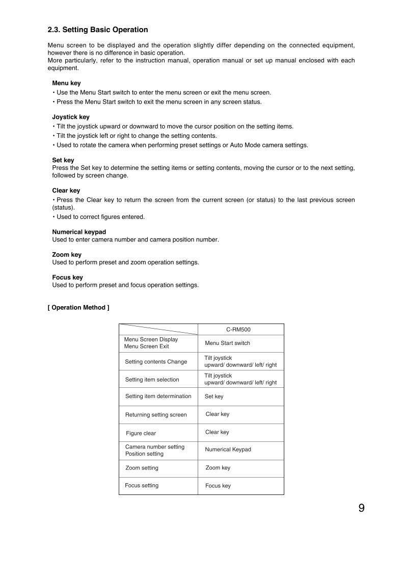
2.3. Setting Basic Operation
Menu screen to be displayed and the operation slightly differ depending on the connected equipment,however there is no difference in basic operation.More particularly, refer to the instruction manual, operation manual or set up manual enclosed with eachequipment.
Menu key• Use the Menu Start switch to enter the menu screen or exit the menu screen.
• Press the Menu Start switch to exit the menu screen in any screen status.
Joystick key• Tilt the joystick upward or downward to move the cursor position on the setting items.
• Tilt the joystick left or right to change the setting contents.
• Used to rotate the camera when performing preset settings or Auto Mode camera settings.
Set keyPress the Set key to determine the setting items or setting contents, moving the cursor or to the next setting,followed by screen change.
Clear key• Press the Clear key to return the screen from the current screen (or status) to the last previous screen(status).
• Used to correct figures entered.
Numerical keypadUsed to enter camera number and camera position number.
Zoom keyUsed to perform preset and zoom operation settings.
Focus keyUsed to perform preset and focus operation settings.
C-RM500
Menu Screen DisplayMenu Screen Exit
Setting contents Change
Setting item selection
Setting item determination
Returning setting screen
Figure clear
Camera number settingPosition setting
Zoom setting
Focus setting
Menu Start switch
Tilt joystick upward/ downward/ left/ right
Tilt joystick upward/ downward/ left/ right
Set key
Clear key
Clear key
Numerical Keypad
Zoom key
Focus key
[ Operation Method ]

10
1. Press the Menu key. (When a password is required,enter it with the numerical keypad.) The menu screenis displayed on the remote controller’s liquid crystaldisplay.
2. With the joystick, select “CAMERA MENU” and pressthe Set key. The display is placed in the standby mode for theentry of a camera number to call up the camera menu.
3. Enter the camera number with the numerical keypad,and press the Set key. The liquid crystal displayshows the selected camera’s camera menu screen.
4. Select the desired item with the joystick, and performthe required settings on each setting screen. Camera menu screen
C A M
E N G L I S H
C A M E R A M E N U
P R E S E T
I D S E T T I N G
C A M E R A S E T T I N G
A U T O M O D E
A L A R M
A U X
T I M E R
M A N U A L
M A I N T E N A N C E
L A N G U A G E
Language selecting screen
C A M
E N G L I S H
C A M E R A M E N U
P R E S E T
I D S E T T I N G
C A M E R A S E T T I N G
A U T O M O D E
A L A R M
A U X
T I M E R
M A N U A L
M A I N T E N A N C E
L A N G U A G E
Menu
O P E R A T I O N M O D E
C A M E R A M E N U * * * C H
DOWN
LEFT RIGHT
UP
SET21(Example)
3. ENTERING CAMERA MENU SCREEN
3.1. Selecting the Language
The language to be displayed on the screen can be selected among English, German, French and Italian.(Factory default: English)
1. Select "LANGUAGE" on the Camera Menu screenwith the joystick, then press the Set key.The arrow moves to “ENGLISH” (factory default).
2. Select "ENGLISH," "DEUTSCH," "FRANÇAIS," or"ITALIANO" with the joystick, then press the Set key.The screen switches to the Menu screen of theselected language.
( )

11
1. Select “PRESET” on the camera menu screen and press the Set key.The Preset Settings screen is displayed.
2. Select “MEMORY” and press the Set key.The arrow key moves in the place of “***.”( )
Preset memory screen
M E M O R Y * * * P O S* P R E S E T *
- - - - - - - - - - - - - - - - - - - - - - - - - - -
1 : O
2 : O3 : O
4 : O
6 : O
5 : O
7 : O
8 : O
9 : X
1 0 : X1 1 : X
1 2 : X
1 4 : X
1 3 : X
1 5 : X
1 6 : X
Preset setting screen
M E M O R Y
R E A D J U S T A L L P O S
M E M O R Y R E S E T
M E M O R Y A L L R E S E T
A U T O R E T U R N
H O M E
P R E S E T F R E E Z E
* * * P O S
N O
O F F
1 P O S
O F F
* P R E S E T *
Camera menu screen
C A M
E N G L I S H
C A M E R A M E N U
P R E S E T
I D S E T T I N G
C A M E R A S E T T I N G
A U T O M O D E
A L A R M
A U X
T I M E R
M A N U A L
M A I N T E N A N C E
L A N G U A G E
3. Enter the camera position number with the numerical keypad,and press the Set key. The place of “***” shows the inputcamera number.
Note: Positions between 1 and 255 can be set.
4. SETTING PRESETS
Settings such as camera direction, lens angular field of view, and focus can be preset in advance. Up to 255positions can be set.
4.1. Entering Presets Into the Memory
NotePositions cannot be preset in the electronic zoom range (p. 37) or in flip mode (p. 68).Presetting is possible only for parts other than the electronic zoom or when the Flip function has beendisabled. It is recommended that the Auto-Flip function (p. 68) be temporarily turned off when entering presetsinto the memory of the C-CC564, C-CC574, C-CC764 or C-CC774.

12
4. Press the Set key.The position setting screen (the selected camera image) isdisplayed.
Note“*** – ***” on the first line of the Setting screen indicates thecamera number on the left and the position number on theright.
5. Operating the joystick, Zoom key, and Focus key, move thecamera to the desired position, then press the Set key. Preset memory setting screen
S E T T I N G* * * - * * *
6. Operate the joystick, Zoom key, and Focus key further more tofine adjust, then press the Set key.The designated camera position for preset memory isperformed.
Preset memory fine setting screen
F I N E S E T T I N G* * * - * * *

13
4.2. Global Preset Memory Correction
This function simultaneously resets all preset camera panning positions. The deviation of one camera positionis measured, based on which all other positions are globally corrected. When performing this globalcorrection, use the position on the telescope side whenever possible.
1. Select “PRESET” on the camera menu screen and press theSet key.The Preset Settings screen is displayed.
2. Select “READJUST ALL POS” with the joystick and press theSet key.
3. Enter the camera position number with the numerical keypad,and press the Set key. The Entered figure is displayed.
4. Press the Set key.Preset memory correction screen is displayed.
NoteIf a number not used for the preset memory setting is entered,that number is displayed, however the preset memorycorrection screen is not displayed. Enter the figures that areused for the preset memory setting.
5. After adjusting the panning direction with the joystick, pressthe Set key. All preset memory positions can be corrected.
Preset setting screen
M E M O R Y
R E A D J U S T A L L P O S
M E M O R Y R E S E T
M E M O R Y A L L R E S E T
A U T O R E T U R N
H O M E
P R E S E T F R E E Z E
* * * P O S
N O
O F F
1 P O S
O F F
* P R E S E T *

14
R E S E T O K ?* * * - * * *
Preset reset confirmation screen
R E S E T * * * P O S* P R E S E T *
- - - - - - - - - - - - - - - - - - - - - - - - - - -
1 : O
2 : O3 : O
4 : O
6 : O
5 : O
7 : O
8 : O
9 : X
1 0 : X1 1 : X
1 2 : X
1 4 : X
1 3 : X
1 5 : X
1 6 : X
1. Select “PRESET” on the camera menu screen and press theSet key. The Preset Settings screen is displayed.
2. Select “MEMORY RESET” with the joystick and press the Setkey.
3. Enter the desired number to be erased with the numericalkeypad, and press the Set key. The Entered figure isdisplayed.
NotePosition No. 1 cannot be deleted. Entering “1” makes the entryinvalid.
4. Press the Set key.The number entered is selected and “RESET OK?” appearsbelow the number.
5. Press the Set key.The stored position is erased.Position setting item screen is displayed after settingcompletion.
Preset setting screen
M E M O R Y
R E A D J U S T A L L P O S
M E M O R Y R E S E T
M E M O R Y A L L R E S E T
A U T O R E T U R N
H O M E
P R E S E T F R E E Z E
* * * P O S
N O
O F F
1 P O S
O F F
* P R E S E T *
4.3. Preset Memory Reset

15
4.4. Preset Memory All ResetDeletes all preset position data.
1. Select “PRESET” on the camera menu screen and press theSet key.The Preset Settings screen is displayed.
Preset setting screen
M E M O R Y
R E A D J U S T A L L P O S
M E M O R Y R E S E T
M E M O R Y A L L R E S E T
A U T O R E T U R N
H O M E
P R E S E T F R E E Z E
* * * P O S
N O
O F F
1 P O S
O F F
* P R E S E T *
2. Select “MEMORY ALL RESET” with the joystick and press theSet key.
3. Select “YES” with the joystick and press the Set key.Deletes all preset position data.
2. Select “AUTO RETURN” with the joystick and press the Setkey.
3. With the joystick, select “OFF,” “5s,” “10s,” “15s,” “20s,” “30s,”“45s,” “1min,” “3min,” or “5min,” then press the Set key. The program to which the camera will automatically return orrelease (OFF) is then set.
NoteThis function operates separately from the automatic returnfunction of the C-RM500, disabling the automatic return holdfunction by way of alarm hold of the C-RM500. If hold function isrequired, use the automatic return function of the C-RM500.
M E M O R Y
R E A D J U S T A L L P O S
M E M O R Y R E S E T
M E M O R Y A L L R E S E T
A U T O R E T U R N
H O M E
P R E S E T F R E E Z E
* * * P O S
N O
O F F
1 P O S
O F F
* P R E S E T *
Preset setting screen
4.5. Automatic Return Setting
This function is used to determine operation when the camera is not controlled at all. The cameraautomatically reverts to the initially set program when the preset period of time elapses after the controller’scontrol has been finished.
1. Select “PRESET” on the camera menu screen and press theSet key. The Preset Settings screen is displayed.

16
M E M O R Y
R E A D J U S T A L L P O S
M E M O R Y R E S E T
M E M O R Y A L L R E S E T
A U T O R E T U R N
H O M E
P R E S E T F R E E Z E
* * * P O S
N O
O F F
1 P O S
O F F
* P R E S E T *
Preset setting screen
2. Select “HOME” with the joystick and press the Set key.
3. With the joystick, select “1POS,” “2POS,” “254POS,”“255POS,” “AUTO PAN,” “SEQUENCE,” “TRACE1,”“TRACE2,” or “TOUR1 – 16,” then press the Set key. Theprogram to which the camera will automatically return is thenset.
Note: Items that have not been set cannot be selected.
1. Select “PRESET” on the camera menu screen and press theSet key. The Preset Settings screen is displayed.
2. Select “PRESET FREEZE” with the joystick and press the Setkey.
3 With the joystick, select “ON,” then press the Set key. The Preset Memory Freeze is then set.
Designate the program the camera automatically returns to.
1. Select “PRESET” on the camera menu screen and press theSet key. The Preset Settings screen is displayed.
4.6. Home Setting
4.7. Preset Memory Freeze Setting (C-CC564, C-CC574, C-CC764 and C-CC774 only)
Freezing the screen immediately before replaying preset memory blanks out the view of the camera’smovement between camera positions. It is recommended that the preset memory freeze function also be usedtogether when using the privacy masking function (p. 77).
M E M O R Y
R E A D J U S T A L L P O S
M E M O R Y R E S E T
M E M O R Y A L L R E S E T
A U T O R E T U R N
H O M E
P R E S E T F R E E Z E
* * * P O S
N O
O F F
1 P O S
O F F
* P R E S E T *
Preset setting screen

17
5.1. Setting Display Content
Contents or time to be displayed can be set by selecting “DISPLAY” on the ID setting screen.
1. Select “ALL” on the ID display screen with the joystick andpress the Set key.
2. With the joystick, select “OFF,” “ON,” “INDIVIDUAL,” “1s,” “3s,”“5s,” or “10s,” then press the Set key. The selected item isthen set.
OFF: Nothing is displayed.ON: Every ID are all displayed.1S, 3S, 5S, 10S: ID is displayed for a set length of time.INDIVIDUAL: Performs display settings for each ID.
A L L
A D D R E S S
C A M E R A I D
P O S I T I O N I D
T R A C E I D
A U T O P A N I D
T O U R I D
H O M E I D
N E X T P A G E
O F F
O F F
O F F
O F F
O F F
O F F
O F F
I N D I V I D U A L* D I S P L A Y *
ID Display screen
When set to “OFF” (factory default).When “Camera,” “Position,” and “Home” are turned ON. When “All Display” is set to ON.
* Example shows display position and its length are factory preset value.
C A M E R A I D
P O S I T I O N
H O M E I D 2 * H O M E I D 3 *
H O M E I D 1 *
A D D R * * *C A M E R A I D
P O S I T I O N
H O M E I D 2 * H O M E I D 3 *
T O U R I D * *M M / D D / Y Y
* * : * * A M
Z O O S E C T O R I D A L A R M I D *H O M E I D 1 * A U X I D * * ** * * / * * *
5. ID (TITLE) SETTINGS
Up to 8 alphanumeric characters can be used. The display position and its length can be freely adjusted.
[ Entering the ID Setting Screen from the Camera Menu Screen ]
First enter the ID setting screen from the camera menu screen to set titles.
1. Select “ID SETTING” on the camera menu screen with the joystick and press the Set key.The ID Settings screen is displayed.
Camera menu screen
C A M
C A M E R A M E N U
P R E S E T
I D S E T T I N G
C A M E R A S E T T I N G
A U T O M O D E
A L A R M
A U X
T I M E R
M A N U A L
M A I N T E N A N C E
E N G L I S HL A N G U A G E
ID Setting screen
D I S P L A Y
I D S E T T I N G
L O C A T I O N
F R A M E A D J U S T
Z E R O P O I N T
* I D S E T T I N G *
2. Select the setting item with the joystick and perform each item setting.

18
5.1.1. Setting display items
Display setting “ON” or “OFF” for each ID can be set by selecting “INDIVIDUAL” on the ID display screen.
1. Select the desired ID on the ID display screen with the joystick and press the Set key.
2. Select “ON” or “OFF” with the joystick and press the Set key.(Setting contents can be displayed on the screen when setting item is set to “ON.”)
Note: The ID setting items that can be displayed are as follows.
Displays the time in accordance with the time (hour, minute) setting (timer setting) format.(Format: fixed 5 or 7-charactors)
Setting Item Setting Contents
Displays the camera address and camera position No. Title length can be freely adjusted from 3 to 7 digits. (Camera address: DIP switch 1: for setting, factory-preset: 001)[ ] Camera address - Position number
Address
Displays the Camera Title. *1 Camera
Displays the Position title (1 – 255). *1 Position
Displays the Trace title (1 – 2). *1 Trace
Maximum character length can be set in the range of1 to 8 characters. (factory default : 8 characters)*1
Displays the Auto-Pan title. *1 Auto-Pan
Displays the Tour title (1 – 16). *1 Tour
Displays the Home Position title (1 – 3). Up to 3 titles can be set.*1 Home
Displays the Alarm title (1 – 8). *1 Alarm
Displays the title for the sectors split in the panning direction. Setting North permits the direction to be automatically divided into 8 sectors. (north, north east, east, south east, south, south west, west, and north west) *1
Sector
Displays the AUX contact output title (1 – 2).AUX
Displays the coordinate. Pan (0 to 359)/ Tilt (5 to -185) fixed 8 characters.[ ] Pan angle (0 to 359)/ Tilt (5 to 185)
Coordinate
Displays the Electronic Zoom. Fixed 3-charactors. Lens
Displays the date in accordance with the date setting (timer setting) format. Fixed 8-charactors.
Date
Time
*** - ***
*** /- ***

19
5.2.2. Position ID setting
1. Select “POSITION” on the ID setting screen 2 with the joystickand press the Set key.
2. Enter the desired position number with the numerical keypad,and press Set key.The place of “***” shows the input ID number.
Note: Position between 1 and 255 can be set.
3. Press the Set key.ID setting screen is displayed.
4. Enter the title characters.(p. 25, Character entry basic operation)
Position ID setting screen
P O S I T I O N * * * P O S- - - - - - - - - - - - - - - - - - - - - - - - - - -
1 : * * * * * * * *
2 : * * * * * * * * 3 : * * * * * * * *
4 : * * * * * * * *
6 : * * * * * * * *
5 : * * * * * * * *
7 : * * * * * * * *
8 : * * * * * * * *
1 0 : * * * * * * * * 1 1 : * * * * * * * *
1 2 : * * * * * * * *
1 4 : * * * * * * * *
1 3 : * * * * * * * *
1 5 : * * * * * * * *
1 6 : * * * * * * * *
* I D S E T T I N G *
9 : * * * * * * * *
5.2.1. Camera ID setting
1. Select “CAMERA” on the ID setting screen 2 with the joystickand press the Set key.ID input screen is displayed.
2. Enter the title characters.(p. 25, Character entry basic operation)
* C A M E R A ** * * * * * * *
S P A C E C L E A R - - - E N DA B C D E F G H I J K L M N O P Q R S T U V W X Y Za b c d e f g h i j k l m n o p q r s t u v w x y z0 1 2 3 4 5 6 7 8 9 ! ? ¿ / ( ) < > : . · , - & *Ä Ö Å Ü Ş ä ö å ü μ à á â ã è é ë ê ç ì í î ñ ò ó õù ú û ô ï β È Ã Ç Æ æ Ø ø Γ Д Ж И Й К Л П Ф Ц Ч Ш ЩЭ Ю Я б в г д ж з и й к л м н п т ф ц ч ш щ ъ ы ь эю я Ą Ć } Ł Ń Ó Ś Ź Ż ą ć � ł ń Ë ś œ ź ż i … § Ñ É Ê À Á Â Ù Û Î Ì Í Ï Ò Õ Ú Ƃ З У Ъ Ы ЬLI II rr ck tz
Ch ch
5.2. ID Settings
1. Select “ID SETTING” on the ID setting screen with the joystickand press the Set key.ID setting screen 2 is displayed.
2. Select the setting item with the joystick to set each ID.
C A M E R A
P O S I T I O N
T R A C E
A U T O P A N
T O U R
H O M E
* I D S E T T I N G *
ID Setting screen 2
A L A R M
S E C T O R
A U X

20
5.2.4. Auto Pan ID setting
1. Select “AUTO PAN” on the ID setting screen 2 with thejoystick and press the Set key. ID setting screen is displayed.
2. Enter the title characters.(p. 25, Character entry basic operation)
* A U T O P A N ** * * * * * * *
S P A C E C L E A R - - - E N DA B C D E F G H I J K L M N O P Q R S T U V W X Y Za b c d e f g h i j k l m n o p q r s t u v w x y z0 1 2 3 4 5 6 7 8 9 ! ? ¿ / ( ) < > : . · , - & *Ä Ö Å Ü Ş ä ö å ü μ à á â ã è é ë ê ç ì í î ñ ò ó õù ú û ô ï β È Ã Ç Æ æ Ø ø Γ Д Ж И Й К Л П Ф Ц Ч Ш ЩЭ Ю Я б в г д ж з и й к л м н п т ф ц ч ш щ ъ ы ь эю я Ą Ć } Ł Ń Ó Ś Ź Ż ą ć � ł ń Ë ś œ ź ż i … § Ñ É Ê À Á Â Ù Û Î Ì Í Ï Ò Õ Ú Ƃ З У Ъ Ы ЬLI II rr ck tz
Ch ch
5.2.3. Trace ID setting
1. Select “TRACE” on the ID setting screen 2 with the joystickand press the Set key.
2. Select the number on the ID setting screen with the joystickand press the Set key.ID setting screen is displayed.
3. Enter the title characters.(p. 25, Character entry basic operation)
Trace ID setting screen
* I D S E T T I N G *T R A C E
2 : * * * * * * * *
1 : * * * * * * * *
5.2.5. Tour ID setting
1. Select “TOUR” on the ID setting screen 2 with the joystick andpress the Set key.
2. Select the number on the Tour ID setting screen with thejoystick, and press Set key.ID setting screen is displayed.
3. Enter the title characters.(p. 25, Character entry basic operation)
Tour ID setting screen
T O U R
1 : * * * * * * * *
2 : * * * * * * * * 3 : * * * * * * * *
4 : * * * * * * * *
6 : * * * * * * * *
5 : * * * * * * * *
7 : * * * * * * * *
8 : * * * * * * * *
1 0 : * * * * * * * * 1 1 : * * * * * * * *
1 2 : * * * * * * * *
1 4 : * * * * * * * *
1 3 : * * * * * * * *
1 5 : * * * * * * * *
1 6 : * * * * * * * *
* I D S E T T I N G *
9 : * * * * * * * *

21
5.2.8. Sector ID setting
1. Select “SECTOR” on the ID setting screen 2 with the joystickand press the Set key.
2. Select “SECTOR SETTING” or “ID SETTING” with the joystick,and press Set key.
“SECTOR SETTING” [ Sector Range setting/ clearing ]
“ID SETTING” [ Sector title settings ] Sector ID setting screen
* S E C T O R *S E C T O R S E T T I N G
I D S E T T I N G
5.2.6. Home ID setting
1. Select “HOME” on the ID setting screen 2 with the joystick andpress the Set key.
2. Select the number on the Home ID setting screen with thejoystick, and press Set key.ID setting screen is displayed.
3. Enter the title characters.(p. 25, Character entry basic operation)
Home ID setting screen
H O M E
1 : * * * * * * * *
2 : * * * * * * * * 3 : * * * * * * * *
* I D S E T T I N G *
5.2.7. Alarm ID setting
1. Select “ALARM” on the ID setting screen 2 with the joystickand press the Set key.
2. Select the number on the Alarm ID setting screen with thejoystick, and press Set key.ID setting screen is displayed.
3. Enter the title characters.(p. 25, Character entry basic operation)
Alarm ID setting screen
A L A R M
1 : * * * * * * * *
2 : * * * * * * * * 3 : * * * * * * * *
4 : * * * * * * * *
6 : * * * * * * * *
5 : * * * * * * * *
7 : * * * * * * * *
8 : * * * * * * * *
* I D S E T T I N G *

22
[ Sector Range setting/ clearing ]
1. Select “FIX,” “EACH,” or “CLEAR” on the sector ID settingscreen with the joystick, and press Set key.
1-1 When “FIX” is selected
Tilt the joystick left or right to move the camera direction tothe “North” position, then press the Set key.Eight directions are automatically set.
Fixed direction screen
N O R T H
S E C T O R S E T T I N G
1-2 When “EACH” is selected
(1) Press the Set key. The arrow moves to a number.
(2) Select the sector to be set with the joystick and press the Setkey.
(3) Tilt the joystick left or right to move the camera direction tothe left position of the sector, then press the Set key.Similarly, with the joystick, move the camera direction to theright position of the sector, then press the Set key.
( ) L E F TS E C T O R S E T T I N G
Individual orientation setting screen
Sector setting screen
* S E C T O R *S E C T O R S E T T I N G F I X
- - - - - - - - - - - - - - - - - - - - - - - - - - -
1 : N O S E T U P
2 : N O S E T U P3 : N O S E T U P
4 : N O S E T U P
6 : N O S E T U P
5 : N O S E T U P
7 : N O S E T U P
8 : N O S E T U P
1
2
3
4
5
6
7
8( NE )
( E )
( SE )
( S )
( SW )
( W )
( NW )
( N )
North
1-3 When “CLEAR” is selected
(1) Press the Set key. The arrow moves to a number.
(2) Select the sector to be cleared with the joystick and press theSet key.
(3) The screen moves to the preset position, then “SECTORCLEAR OK?” is displayed. Press the Set key.
( )
Clear screen
S E C T O R C L E A R O K ?

23
[ Sector title settings ]
1. Select “ID SETTING” on the Sector ID setting screen with thejoystick and press the Set key.When “Fixed direction” is selected, “N,” “NE,” “E,” “SE,” “S,”“SW,” “W,” and “NW” titles are displayed automatically in theorder of 1 – 8. These titles can be changed freely.
2. Select the ID number, and press Set key.ID setting screen is displayed.
3. Enter the title characters.(p. 25, Character entry basic operation)
5.2.9. AUX ID setting
1. Select “AUX” on the ID setting screen 2 with the joystick andpress the Set key.
2. Select the number on the AUX ID setting screen with thejoystick and press the Set key. ID setting screen is displayed.
3. Enter the title characters.(p. 25, Character entry basic operation)
NoteAUX2 : C-CC564 and C-CC574 only
AUX ID setting screen
* I D S E T T I N G *A U X
1 : * * * * * * * *
2 : * * * * * * * *
Sector ID setting screen
* S E C T O R *S E C T O R
1 : N
2 : N E3 : E
4 : S E
6 : S W
5 : S
7 : W
8 : N W

24
5.3. Entering Title Characters
5.3.1. Understanding the ID Entry screen
ID Entry screen
(Close-up View of the above display)
Character Selection AreaThis area is used to select the characters to be used in the title.
Title Display AreaThe title is displayed here. A title may be up to 8 characters long.
Clears all of the characters entered for a title.
Select when entering code.
Completes title setting.
Moves the Title Display Area arrow one place to the right.
Moves the Title Display Area arrow one place to the left.
Inserts a single space.
* C A M E R A ** * * * * * * *
S P A C E C L E A R - - - E N DA B C D E F G H I J K L M N O P Q R S T U V W X Y Za b c d e f g h i j k l m n o p q r s t u v w x y z0 1 2 3 4 5 6 7 8 9 ! ? ¿ / ( ) < > : . · , - & *Ä Ö Å Ü Ş ä ö å ü μ à á â ã è é ë ê ç ì í î ñ ò ó õù ú û ô ï β È Ã Ç Æ æ Ø ø Γ Д Ж И Й К Л П Ф Ц Ч Ш ЩЭ Ю Я б в г д ж з и й к л м н п т ф ц ч ш щ ъ ы ь эю я Ą Ć } Ł Ń Ó Ś Ź Ż ą ć � ł ń Ë ś œ ź ż i … § Ñ É Ê À Á Â Ù Û Î Ì Í Ï Ò Õ Ú Ƃ З У Ъ Ы ЬLI II rr ck tz
Ch ch
* C A M E R A ** * * * * * * *
S P A C E C L E A R - - - E N D
• Within the ID Entry screen, arrows appear in both the Title Display Area and the Character Selection Area.The arrow within the Character Selection Area can be moved with the joystick.
• Each time the arrow in the Title Display Area is moved one place to the right when the Set key is pressedafter selecting a character in the Character Selection area.If you wish to move only the arrow, select the “left” or “right” and press the Set key to move the arrow oneplace to the left or right.

25
5.3.3. Erasing or correcting characters
[ To erase all characters ]
1. On the ID Entry screen, move the arrow over the“CLEAR” with the joystick, then press the Set key.
All of the characters in the Title Display Area are erased.
2. Enter new characters according to the character entry basicoperations.
[ To correct only selected characters ]
1. On the ID Entry screen, move the arrow to “Left” or“Right”, then press the Set key.The arrow in the Title Display Area moves one place tothe selected direction.
2. Repeat Step 1 to move the arrow in the Title DisplayArea until it is positioned over the desired character.
3. Enter new characters according to the character entry basicoperations.
( )
( )
( )
( )
* C A M E R A *A B C * * * * *
S P A C E C L E A R - - - E N DA B C D E F G H I J K L M N O P Q R S T U V W X Y Za b c d e f g h i j k l m n o p q r s t u v w x y z0 1 2 3 4 5 6 7 8 9 ! ? ¿ / ( ) < > : . · , - & *Ä Ö Å Ü Ş ä ö å ü μ à á â ã è é ë ê ç ì í î ñ ò ó õù ú û ô ï β È Ã Ç Æ æ Ø ø Γ Д Ж И Й К Л П Ф Ц Ч Ш ЩЭ Ю Я б в г д ж з и й к л м н п т ф ц ч ш щ ъ ы ь эю я Ą Ć } Ł Ń Ó Ś Ź Ż ą ć � ł ń Ë ś œ ź ż i … § Ñ É Ê À Á Â Ù Û Î Ì Í Ï Ò Õ Ú Ƃ З У Ъ Ы ЬLI II rr ck tz
Ch ch
ID entry screen (Correction)
* C A M E R A *A B C * * * * *
S P A C E C L E A R - - - E N DA B C D E F G H I J K L M N O P Q R S T U V W X Y Za b c d e f g h i j k l m n o p q r s t u v w x y z0 1 2 3 4 5 6 7 8 9 ! ? ¿ / ( ) < > : . · , - & *Ä Ö Å Ü Ş ä ö å ü μ à á â ã è é ë ê ç ì í î ñ ò ó õù ú û ô ï β È Ã Ç Æ æ Ø ø Γ Д Ж И Й К Л П Ф Ц Ч Ш ЩЭ Ю Я б в г д ж з и й к л м н п т ф ц ч ш щ ъ ы ь эю я Ą Ć } Ł Ń Ó Ś Ź Ż ą ć � ł ń Ë ś œ ź ż i … § Ñ É Ê À Á Â Ù Û Î Ì Í Ï Ò Õ Ú Ƃ З У Ъ Ы ЬLI II rr ck tz
Ch ch
ID entry screen (Erasure)
5.3.2. Character entry basic operation
The arrow is positioned on the “RIGHT” in the Character Selection Area.
1. Move the arrow to the desired character in the CharacterSelection Area, then press the Set key.The selected character appears at the in the Title DisplayArea and the position pointed by the arrow in the TitleDisplay Area moves one place to the right.
NoteIf title characters have been entered already in the TitleDisplay Area, that character is overwritten by the newcharacter.
2. Repeat Step 1 until the whole title is entered.
3. After completion of title entry, move the arrow in theCharacter Selection Area to “END”, then press the Set key.The title is recorded in the memory.
( )
( )
( )
( )* C A M E R A ** * * * * * * *
S P A C E C L E A R - - - E N DA B C D E F G H I J K L M N O P Q R S T U V W X Y Za b c d e f g h i j k l m n o p q r s t u v w x y z0 1 2 3 4 5 6 7 8 9 ! ? ¿ / ( ) < > : . · , - & *Ä Ö Å Ü Ş ä ö å ü μ à á â ã è é ë ê ç ì í î ñ ò ó õù ú û ô ï β È Ã Ç Æ æ Ø ø Γ Д Ж И Й К Л П Ф Ц Ч Ш ЩЭ Ю Я б в г д ж з и й к л м н п т ф ц ч ш щ ъ ы ь эю я Ą Ć } Ł Ń Ó Ś Ź Ż ą ć � ł ń Ë ś œ ź ż i … § Ñ É Ê À Á Â Ù Û Î Ì Í Ï Ò Õ Ú Ƃ З У Ъ Ы ЬLI II rr ck tz
Ch ch
ID entry screen

26
5.3.4. Entering title using code
1. On the ID code entry screen, move the arrow to “---” ,then press the Set key.The “---” indication turns to “000” indication.
2. Select the desired entry code number with the joystick andpress the Set key.The figure can be set in 1-digit settings. The arrow movesone place to the right each time 1-digit is confirmed.
Notes• The figures cannot be entered with the Numerical keypad.• The figure increases by one when the joystick is tilted to the
right and decrease by one when tilted to the left.• When entering the code, refer to p. 27 “ID Code Table.”
3. Repeat Step 2 to enter the 3-digit ID code, then press the Setkey.The character corresponding to the entered code is displacedto the arrow position in the Title Display area.
NoteWhen the figure not listed on “ID Code Table” is entered, theindication in “---” is disappeared, while leaving the ID entryscreen unchanged.
( )
( )
( )
S P A C E C L E A R - - - E N D
S P A C E C L E A R 0 1 0 E N D
* C A M E R A ** * * * * * * *
S P A C E C L E A R - - - E N DA B C D E F G H I J K L M N O P Q R S T U V W X Y Za b c d e f g h i j k l m n o p q r s t u v w x y z0 1 2 3 4 5 6 7 8 9 ! ? ¿ / ( ) < > : . · , - & *Ä Ö Å Ü Ş ä ö å ü μ à á â ã è é ë ê ç ì í î ñ ò ó õù ú û ô ï β È Ã Ç Æ æ Ø ø Γ Д Ж И Й К Л П Ф Ц Ч Ш ЩЭ Ю Я б в г д ж з и й к л м н п т ф ц ч ш щ ъ ы ь эю я Ą Ć } Ł Ń Ó Ś Ź Ż ą ć � ł ń Ë ś œ ź ż i … § Ñ É Ê À Á Â Ù Û Î Ì Í Ï Ò Õ Ú Ƃ З У Ъ Ы ЬLI II rr ck tz
Ch ch
ID code entry screen

27
5.3.5. ID code table

28
5.4. ID Display Position Settings
5.4.1. Setting the common title display position and its length
Set the title display position and its length common to all camera positions. It is also possible to set the titledisplay position and its length (pattern settings) individually for each camera position. When setting the displayposition, each “Display” ID on the ID setting screen must be set to ON.
1. With the joystick, select “LOCATION SETTING” on the IDsetting screen and press the Set key.
2. Select each setting item with the joystick and perform itssettings.
ID display position setting screen
* L O C A T I O N S E T T I N G *A D D R E S S
C A M E R A
P O S I T I O N
T O U R
H O M EA L A R M
S E C T O R
N E X T P A G E
[ Setting the ID display positions for the address, coordinate, zoom, date, and time ]
1. With the joystick, select each ID selection screen for ID displayposition settings and press the Set key. The arrow is displayed at the selected ID on the IDdisplay position setting screen.
2. Use the joystick to select each setting item and perform itssettings.
NoteWhen the selected title coincides with another title, theselected title takes precedence, causing the other title to bemoved so as not to coincide with the selected title.
( )
Position setting screen
Example when “Address * * * is selected”
A D D R * * *A M E R A I D
P O S I T I O N
H O M E I D 2 * H O M E I D 3 *
T O U R I D * *M M / D D / Y Y
* * : * * A M
Z O O S E C T O R I D A L A R M I D *H O M E I D 1 * A U X I D * * ** * * / * * *

29
[ Setting the Home title display position and the length ]
1. With the joystick, select Home ID selection screen for IDdisplay position settings and press the Set key.
2. With the joystick, select “LOCATION SETTING” or “LENGTHSETTING” and press the Set key.
2-1 When “LOCATION SETTING” is selected
(1) With the joystick, select “HOME” number and press the Setkey.The arrow is displayed at the selected ID on the IDdisplay position setting screen.
(2) Use the joystick to select each setting item and perform itssettings. The position is confirmed at the selected position.
2-2 When “LENGTH SETTING” is selected
(1) With the joystick, select “HOME” number and press the Setkey.
(2) With the joystick, adjust the title length, then press the Setkey.The arrow is displayed at the last character of theselected title.
( )
( )
ID display position setting screen
* H O M E *
L O C A T I O N S E T T I N G
L E N G T H S E T T I N G
H O M E 1
H O M E 1
ID length setting screen
A D D R * * *C A M E
P O S T I O N
H O M E I D 2 * H O M E I D 3 *
T O U R I D * *M M / D D / Y Y
* * : * * A M
Z O O S E C T O R I D A L A R M I D *H O M E I D 1 * A U X I D * * ** * * / * * *
Example: When setting the camera ID length to 4 characters
[ Setting the ID display positions and lengths for the camera, position, tour, alarm, sector and AUX ]
1. With the joystick, select each ID selection screen for ID displayposition settings and press the Set key.
2. With the joystick, select “LOCATION SETTING” or “ LENGTHSETTING” and press the Set key.
2-1 When “LOCATION SETTING” is selectedThe arrow is displayed at the selected ID on the IDdisplay position setting screen.
(1) Use the joystick to select each setting item and perform itssettings.The position is confirmed at the selected position.
2-2 When “LENGTH SETTING” is selected
(1) Adjust the title length with the joystick, then press the Setkey.The arrow is displayed over the last character of theselected title.
( )
( )
ID display position and its length setting screen
Example: When setting Camera ID position
* C A M E R A *
L O C A T I O N S E T T I N G
L E N G T H S E T T I N G
A D D R * * *C A M E R A I D
P O S I T I O N
H O M E I D 2 * H O M E I D 3 *
T O U R I D * *M M / D D / Y Y
* * : * * A M
Z O O S E C T O R I D A L A R M I D *H O M E I D 1 * A U X I D * * ** * * / * * *
Home ID setting screen
Example shows "Home ID 1 * * * ."

30
5.5. Frame Adjustment Setting
Adjust the character display position.
1. With the joystick, select “FRAME ADJUST” on the ID settingscreen and press the Set key.
2. With the joystick, move the character display position with theindicated markers as a guide, then press the Set key.Titles and menu character display positions are adjustedsimultaneously.
Frame adjustment setting screen
5.6. Angle Origin Point (Zero point) Change
Change the origin point of the angle (Zero point) display.
1. With the joystick, select “ZERO POINT SETTING” on the IDsetting screen, and press the Set key.
2. Use the joystick to With the joystick (after tilting upward anddownward, tilt left and right when the controller other than theC-RM500 is connected), move to the position to be set as theorigin point (0°/ 0°), then press the Set key.
NoteOnce the setting has been made, it cannot be cleared unless itis reset to factory settings. Angle origin point setting screen
Z E R O P O I N T S E T T I N G
* * * / - * * *
5.4.2. Initializing the common title display position
All set display positions and lengths can be reset to initial factory-preset conditions.
1. With the joystick, select “PATTERN CLEAR” on the ID settingscreen and press the Set key. The arrow moves to the “NO” position.
2. With the joystick, select “YES,” then press the Set key. The title setting position and its length revert to factory-presetconditions.
( )
* L O C A T I O N S E T T I N G *A U X
A N G L E D I S P
Z O O M D I S P
D A T E D I S P
T I M E D I S P
P A T T E R N C L E A R
F R O N T P A G E
P A T T E R N C L E A R Y E S

31
6. CAMERA CHARACTERISTIC SETTINGS
Camera characteristics can be individually set for each camera. There are 14 types of setting functions and setting initializations: white balance, backlight compensation,brightness, day & night *1, auto-focus, AGC, slow shutter, shutter speed, electronic zoom, enhancer, colordepth, synchronization, EIS *2 and sensitivity *2.Settings can be changed for individual positions except synchronization, auto-focus, electronic zoom, EIS andsensitivity settings (p. 80)
*1 C-CC564, C-CC574, C-CC764 and C-CC774 only*2 C-CC574 and C-CC774 only
[ Entering the Camera Setting Screen from the Camera Menu Screen ]
The camera setting screen to be displayed differs slightly depending on the equipment connected, howeverthere is no difference in basic operation.
1. With the joystick, select “CAMERA SETTING” on the CameraMenu screen, and press the Set key.The arrow moves over “CAM.”
2. Press the Set key during the arrow is indicated over “CAM” todisplay the camera setting screen.
3. With the joystick, select the setting item, then perform eachitem settings.
( ) C A M
C A M E R A M E N U
P R E S E T
I D S E T T I N G
C A M E R A S E T T I N G
A U T O M O D E
A L A R M
A U X
T I M E R
M A N U A L
M A I N T E N A N C E
Camera menu screen
E N G L I S HL A N G U A G E
- - - - - -
- *- - - - - -
*
* C A M E R A S E T T I N G *W H I T E B A L A N C E
B A C K L I G H T
D A Y / N I G H T
A U T O F O C U S
A G C
S L O W S H U T T E R
S H U T T E R S P E E D
N E X T P A G E
B R I G H T N E S S
A T W
R B
O F F
N O R M A L
O N E P U S H
A U T O
X 3 2
N O R M A L
-
White Balance setting screen

32
6.1. Setting the White Balance
The white balance may be set to either AWB or ATW. (factory default: ATW)
ATW: The camera adjusts its white balance setting according to fluctuations in the color temperature of thesubject’s illumination.
AWB: The camera uses a fixed white balance setting regardless of fluctuations in the color temperature of thesubject’s illumination.
NoteThe ATW will not work when the High-Sensitivity Slow Shutter function is active.It is also possible to change these settings for arbitrarily positions. (p. 80)
1. With the joystick, select the “WHITE BALANCE” on thecamera setting screen, then press the Set key.The arrow moves to “ATW” (factory default).
2. Select “AWB” or “ATW” with the joystick, then press the Setkey.The arrow moves over the setting bar.
3. Move “*” at the appropriate position with the joystick, thenpress the Set key.The White Balance setting is recorded.
( )
( )- - - - - -
- *- - - - - -
*
* C A M E R A S E T T I N G *W H I T E B A L A N C E
B A C K L I G H T
D A Y / N I G H T
A U T O F O C U S
A G C
S L O W S H U T T E R
S H U T T E R S P E E D
N E X T P A G E
B R I G H T N E S S
A T W
R B
O F F
N O R M A L
O N E P U S H
A U T O
X 3 2
N O R M A L
-
White Balance setting screen
- - - - - -*
W H I T E B A L A N C E A T W
R B

33
1. With the joystick, select “BACKLIGHT” on the Camera Settingscreen, then press the Set key.The arrow moves over “OFF” (factory default).
2. Select the desired item with the joystick, then press the Setkey.If “OFF,” “WIDE DYNAMIC2,” “PATTERN1,” “PATTERN2,” or“PATTERN3” is selected, the Backlight Compensation settingis recorded and the arrow moves to “BACKLIGHT.”If “WIDE DYNAMIC” is selected, the arrow moves to“Wide Dynamic compensation Level Adjustment” screen.Proceed to Step 3 to adjust the compensation level.
3. Move “*” at the appropriate position with the joystick, thenpress the Set key.The Backlight Compensation setting is recorded and the arrow
moves to “BACKLIGHT.”( )
( )
( )
( )
6.2. Setting the Backlight Compensation
The Backlight Compensation function makes the image displayed on the screen easier to see when there isstrong light behind the subject.Backlight Compensation may be set to “OFF,” “WIDE DYNAMIC *1,” “WIDE DYNAMIC2 *2,” “PATTERN1,”“PATTERN2,” or “PATTERN3.” (factory default: OFF)
*1 C-CC564, C-CC574, C-CC764 andC-CC774 only.*2 C-CC574 andC-CC774 only.
OFF:Turns the Backlight Compensation function off. This is the setting usually used.
WIDE DYNAMIC:Allows backlight compensation that prevents the subject from becoming too dark or the surroundingbackground from becoming too white. When with the C-CC564, C-CC574, C-CC764 andC-CC774, try usingWIDE DYNAMIC as the initial setting to compensate for backlighting.
WIDE DYNAMIC2:Allows objects in a dark location with a bright background to be distinguished, which cannot be achieved byWide Dynamic. However, the bright background may look darker.
PATTERN1, PATTERN2 or PATTERN3:Turns the Backlight Compensation function on. This automatically adjusts the overall brightness so thatbrightness is optimized for easier viewing in the screen areas indicated in shaded region. Select 1, 2, or 3depending on which makes the intended subject the easiest to see.
Notes• Backlight compensation will not function whenever the Auto-Flip function (p. 68) is engaged (when the actual
image-flipping is taking place).
• It is possible to make settings different from these for arbitrarily positions. (p. 80)
PATTERN 1 PATTERN 2 PATTERN 3
Backlight compensation setting screen
- - - - - -
- *- - - - - -
*
* C A M E R A S E T T I N G *W H I T E B A L A N C E
B A C K L I G H T
D A Y / N I G H T
A U T O F O C U S
A G C
S L O W S H U T T E R
S H U T T E R S P E E D
N E X T P A G E
B R I G H T N E S S
A T W
R B
O F F
N O R M A L
O N E P U S H
A U T O
X 3 2
N O R M A L
-
Wide dynamic compensation level adjustment screen
L E V E L
L H
- - - - - - - - - -*

34
6.3. Adjusting the Brightness
The brightness of the camera image can be adjusted to suit user preferences.
NoteIt is possible to make settings different from these for arbitrarily positions. (p. 80)
1. With the joystick, select the “BRIGHTNESS” on the CameraSetting screen, then press the Set key.The arrow moves over the setting bar.
2. Move “*” at the appropriate position with the joystick, thenpress the Set key.The Brightness setting is recorded.
NoteMoving “*” further to the right increases the brightness of thecamera image.
( )
Brightness setting screen
- - - - - -
- *- - - - - -
*
* C A M E R A S E T T I N G *W H I T E B A L A N C E
B A C K L I G H T
D A Y / N I G H T
A U T O F O C U S
A G C
S L O W S H U T T E R
S H U T T E R S P E E D
N E X T P A G E
B R I G H T N E S S
A T W
R B
O F F
N O R M A L
O N E P U S H
A U T O
X 3 2
N O R M A L
-
- *- - - - -B R I G H T N E S S - +
6.4. Setting the Day and Night (C-CC564, C-CC574, C-CC764 and C-CC774 only)
This function gives operation priority to black & white mode or slow shutter mode depending on the subjectbrightness. Choose from “COLOR,” “MOTION,” “NORMAL,” “ON,” and “OFF.” (factory default: NORMAL)
COLOR: Slow shutter mode takes operating precedence. When a moving subject is photographed, thepicture is like the one shot during camera movement, but can be viewed in color.
MOTION: Black & white mode takes operating precedence. Even if a moving subject is photographed, clearpictures can be provided.
NORMAL: Balanced black & white mode and slow shutter operation.
ON: Turns on black & white mode, and always provides black and white pictures.
OFF: Turns off black & white mode and always provides color pictures.
NoteIf NORMAL, COLOR, or MOTION is selected, it may take a relatively long time before the black & white modeswitches over to color mode when shooting such subjects as a sunrise that slowly becomes bright.
1. With the joystick, select the “DAY/ NIGHT” on the CameraSetting screen, then press the Set key.The arrow moves over “OFF” (factory default).
2. Select “COLOR,” “MOTION,” “NORMAL,” “ON,” or “OFF” withthe joystick, then press the Set key.The selected contents are recorded.
( )
Day and night setting screen
- - - - - -
- *- - - - - -
*
* C A M E R A S E T T I N G *W H I T E B A L A N C E
B A C K L I G H T
D A Y / N I G H T
A U T O F O C U S
A G C
S L O W S H U T T E R
S H U T T E R S P E E D
N E X T P A G E
B R I G H T N E S S
A T W
R B
O F F
N O R M A L
O N E P U S H
A U T O
X 3 2
N O R M A L
-

35
6.6. Setting the AGC
The automatic gain controller (AGC) can be set to “AUTO,” “OFF,” or “MAX.” (Factory default: Auto)
AUTO: Automatically adjusts the gain depending on the subject’s brightness level.OFF: Disables the automatic gain control function.MAX: Used when the subject brightness is insufficient when in AUTO mode.
NoteOperation in “MAX” mode may cause excessive vertical noise, however this is not a failure. If it becomesannoying, select “AUTO” mode.
1. With the joystick, select “AGC” on the Camera Setting screen,then press the Set key.The arrow moves to “AUTO” (factory default).
2. Select “AUTO,” “OFF,” or “MAX” with the joystick, then pressthe Set key.The AGC setting is recorded.
( )
AGC setting screen
- - - - - -
- *- - - - - -
*
* C A M E R A S E T T I N G *W H I T E B A L A N C E
B A C K L I G H T
D A Y / N I G H T
A U T O F O C U S
A G C
S L O W S H U T T E R
S H U T T E R S P E E D
N E X T P A G E
B R I G H T N E S S
A T W
R B
O F F
N O R M A L
O N E P U S H
A U T O
X 3 2
N O R M A L
-
- - - - - -
- *- - - - - -
*
* C A M E R A S E T T I N G *W H I T E B A L A N C E
B A C K L I G H T
D A Y / N I G H T
A U T O F O C U S
A G C
S L O W S H U T T E R
S H U T T E R S P E E D
N E X T P A G E
B R I G H T N E S S
A T W
R B
O F F
N O R M A L
O N E P U S H
A U T O
X 3 2
N O R M A L
-
Auto focus setting screen
6.5. Setting the Auto Focus
There are 3 auto-focus modes: “ONE PUSH,” “STOP AF,” and “CONTINUOUS” modes.(Factory default: ONE PUSH)
ONE PUSH: Auto focusing is operated when the Auto-focus key is pressed.
STOP AF: Auto focusing is automatically operated after the camera scene or angle of view has beenchanged. The STOP AF function does not work when the Focus key is used. Pressing theAuto-focus key again will put the camera in the STOP AF mode.
CONTINUOUS:The Auto-focus function is always operated. However, it cannot be used after preset playback(including Home Position). In this event, the Auto-focus function can be used through manualoperations. Also, the Auto-focus function cannot be used if the Auto-focus key is pressed, andcan be used if the Auto-focus key is pressed again.
Notes• Use “ONE PUSH” mode in normal operations. The use of “STOP AF” or “CONTINUOUS” mode may shorten
the life of lens.
• In the following cases, the subject may not be brought into focus using the Auto-focus function.• When part of the subject shines brightly.• When the distant and near subjects exist together.• When the camera shoots a blind or other subject with horizontal stripes.• When the subject’s lighting conditions are poor.• When the camera rotates at high speed.
1. With the joystick, select “AUTO FOCUS” on the CameraSetting screen, then press the Set key.The arrow moves over “ONE PUSH” (factory default).
2. Select “ONE PUSH,” “STOP AF,” or “CONTINUOUS” with thejoystick, then press the Set key.The selected content is recorded.
( )

36
6.7. Setting the Slow Shutter (High Sensitivity)
The camera is automatically placed in slow shutter mode depending on subject brightness. The slow shutterlimit can be set by selecting “OFF,” “X2,” “X4,” “X8,” “X16,” or “X32.” (Factory default: X32)The Slow Shutter function cannot be used when set to OFF.
NoteIf C-CC564, C-CC574, C-CC764 or C-CC774 is connected, slow shutter will not function whenever the Auto-Flip function (p. 68) is engaged (when the actual image-flipping is taking place).
1. With the joystick, select “SLOW SHUTTER” on the CameraSetting screen, then press the Set key.The arrow moves to “X32” (factory default).
2. Select “OFF,” “X2,” “X4,” “X8,” “X16,” or “X32” with the joystick,then press the Set key.The selected content is recorded.
( )
Slow shutter setting screen
- - - - - -
- *- - - - - -
*
* C A M E R A S E T T I N G *W H I T E B A L A N C E
B A C K L I G H T
D A Y / N I G H T
A U T O F O C U S
A G C
S L O W S H U T T E R
S H U T T E R S P E E D
N E X T P A G E
B R I G H T N E S S
A T W
R B
O F F
N O R M A L
O N E P U S H
A U T O
X 3 2
N O R M A L
-
6.8. Setting the Shutter Speed
Fixed shutter speed can be selected from “NORMAL,” “1/100,” “1/120 (PAL:1/150),” “1/250,” “1/500,” “1/1000,”“1/2000,” “1/4000,” or “1/10000.”(Factory default: NORMAL)
Notes• If speed other than NORMAL is selected, the Wide Dynamic function (p. 33), the Day & Night function
(p. 34), and the Slow Shutter function (p. 36) cannot be used.
• Avoid selecting shutter speed of 1/100 for the purposes of reducing flicker as the unit is performingautomatic flicker control*1.
*1 Operates to reduce flickering of the image that may occur when a subject is shot by a camera underfluorescent lamps used in 50 Hz areas.
• Usually use NORMAL setting.
• It is possible to make settings different from these for arbitrarily positions. (p. 80)
1. With the joystick, select “SHUTTER SPEED” on the CameraSetting screen, then press the Set key.The arrow moves to “NORMAL” (factory default).
2. Select “NORMAL,” “1/100,” “1/120 (PAL:1/150),” “1/250,”“1/500,” “1/1000,” “1/2000,” “1/4000,” or “1/10000” with thejoystick, then press the Set key.The selected content is recorded.
( )- - - - - -
- *- - - - - -
*
* C A M E R A S E T T I N G *W H I T E B A L A N C E
B A C K L I G H T
D A Y / N I G H T
A U T O F O C U S
A G C
S L O W S H U T T E R
S H U T T E R S P E E D
N E X T P A G E
B R I G H T N E S S
A T W
R B
O F F
N O R M A L
O N E P U S H
A U T O
X 3 2
N O R M A L
-
Shutter speed setting screen

37
6.9. Setting the Electronic Zoom
Electronic Zoom*1 is used to enlarge the view of the subject more than is possible with normal optical zoom*2
. A maximum enlargement can be set for the Electronic Zoom. It is also possible to set the zoom to stop for amoment before switching from optical to electronic zoom. (factory default: X12)
OFF: Turns the Electronic Zoom function off.
X2, X4, X8, X12:Engages the Electronic Zoom function. The numbers indicate the maximum electronic zoom enlargement.When the Zoom key (telephoto) is pressed and held, zooming stops for a moment before switching toelectronic zoom. Pressing the Zoom key (telephoto) again continues the image enlargement via ElectronicZoom.
X2 CONT, X4 CONT, X8 CONT, X12 CONT:Engages the Electronic Zoom function. The numbers indicate the maximum electronic zoom enlargement.When the Zoom key (telephoto) is pressed and held, zooming switches from optical to electronic zoom withoutstopping so that the zooming proceeds continuously until it reaches the maximum enlargement.
*1 The zoom function through an optical lens.*2 Electronically enlarges or reduces the image by processing stored image signals through an image pick-
up sensor. The more the magnification of electronic zoom multiplies, the rougher screen images arecaused.
1. With the joystick, select “E-ZOOM” on the Camera Settingscreen, then press the Set key.The arrow moves to “X12” (factory default).
2. Select “OFF,” “X2,” “X4,” “X8,” “X12,” “X2CONT,” “X4CONT,”“X8CONT,” or “X12CONT” with the joystick, then press the Setkey.The electronic zoom function is recorded.
( )
Electronic zoom function setting screen
- *- - - - - -
* C A M E R A S E T T I N G *E - Z O O M
C H R O M A
S Y N C
E I SS E N S I T I V I T YR E S E T ( C A M S E T T I N G )
F R O N T P A G E
E N H A N C E R
I N T
O F FO F FN O
X 1 2
-
- *- - - - - --
E N H A N C E R - *- - - - -- +
6.10. Setting the Enhancer Function
The Enhancer function enhances the contours within the camera image. It may be adjusted to suit userpreferences.
1. With the joystick, select “ENHANCER” on the Camera Settingscreen, then press the Set key.The arrow moves over “*” on the setting bar.
2. Move “*” at the appropriate position with the joystick, thenpress the Set key.The Enhancer setting is recorded.
NoteMoving “*” further to the right on the setting bar increases thecontour enhancement.
( )
Enhancer setting screen
- *- - - - - -
* C A M E R A S E T T I N G *E - Z O O M
C H R O M A
S Y N C
E I SS E N S I T I V I T YR E S E T ( C A M S E T T I N G )
F R O N T P A G E
E N H A N C E R
I N T
O F FO F FN O
X 1 2
-
- *- - - - - --

38
6.12. Changing the Synchronization System
The camera’s sync system can be switched to the system that uses the power frequency. It is also possible toadjust the phase. (Factory default: INT.)
INT: Represents the internal sync system. Select this setting when only a single camera is used and it is notnecessary to synchronize it with other camera.
LL: Represent the power sync system. Select this setting when synchronizing 2 or more cameras using thepower frequency. Note that when the screen is switched by the sequential switcher, etc., the picturemay be distorted depending on the camera installation conditions, such as the distance to the powersource. In such cases, adjust the phase to prevent the picture distortion from occurring. The phase canbe adjusted in 83 – step ranging from “00” to “82” for NTSC system and in 100 – step ranging from “00”to “99” for PAL system.
Notes• NTSC Systems of LL cannot be used in the 50Hz area.• PAL Systems of LL cannot be used in the 60Hz area.
1. With the joystick, select “SYNC” on the Camera Settingscreen, then press the Set key.The arrow moves to “INT” (factory default).
2. Select “INT” or “LL” which you wish with the joystick, thenpress the Set key.Selecting “INT” will record the sync system setting, and thearrow will move to “SYNC”. When “LL” is selected, thearrow moves over “*” position on the phase adjustmentbar. Proceed to Step 3. (factory default: 00)
3. Adjust the phase with the joystick, then press the Set key.The sync system setting is recorded.
( )
( )
( )
Synchronization changing screen
- *- - - - - -
* C A M E R A S E T T I N G *E - Z O O M
C H R O M A
S Y N C
E I SS E N S I T I V I T YR E S E T ( C A M S E T T I N G )
F R O N T P A G E
E N H A N C E R
I N T
O F FO F FN O
X 1 2
-
- *- - - - - --
S Y N C L L0 0
- * - - - - - -C H R O M A +
6.11. Setting the Chroma
The chroma may be adjusted to suit user preferences.
1. With the joystick, select “CHROMA” on the Camera Settingscreen, then press the Set key.The arrow moves over “*” on the setting bar.
2. Move “*” at the appropriate position with the joystick, thenpress the Set key.The Chroma setting is recorded.
NoteMoving “*” further to the right in the setting bar increases thecontour density.
( )
Chroma setting screen
- *- - - - - -
* C A M E R A S E T T I N G *E - Z O O M
C H R O M A
S Y N C
E I SS E N S I T I V I T YR E S E T ( C A M S E T T I N G )
F R O N T P A G E
E N H A N C E R
I N T
O F FO F FN O
X 1 2
-
- *- - - - - --

39
6.13. Electronic Image Stabilization Settings (C-CC574 and C-CC774 only)
Screen vibrations can be reduced. (Factory default: OFF)
OFF: No image stabilization performed.ON1: Use this mode for relatively quick screen vibration.ON2: Use this mode for relatively slow screen vibration.
Notes• Setting Electronic Image Stabilization to ON narrows the view angle and prevents the electronic zoom
magnification from exceeding 1.8-times.• When Electronic Image Stabilization is set to ON, the Slow Shutter, Wide Dynamic and Motion Detection
functions cannot be used.• When Electronic Image Stabilization is set while Backlight Correction is set to Wide Dynamic, the Backlight
Correction setting reverts to its default OFF setting.• Significant vibration may not be corrected even with Electronic Image Stabilization enabled.• The screen may vibrate when the camera stops during pan/tilt operations, even if the Electronics Image
Stabilization function is used.
1. Select "EIS" from the Camera Settings screen using thejoystick and press the Set key. The arrow moves to the OFF indication (default setting).
2. Select "ON1" or "ON2" using the joystick, then press the Setkey. The Electronic Image Stabilization function is set.
( )
6.14. Sensitivity-Up Settings (C-CC574 and C-CC774 only)
This function increases sensitivity. Selecting ON doubles the sensitivity. (Factory default: OFF)
Notes• Selecting Sensitivity "ON" disables both the Motion Detection and Wide Dynamic functions. (They are
deleted from the menu display.)• This function is switched to the selected "ON" or "OFF" mode when the Set key is pressed. The indication
“SETTING” is displayed when the mode is switched. • When Sensitivity-Up is set while Backlight Correction is set to Wide Dynamic, the Backlight Correction
setting reverts to its default OFF setting.• Setting Sensitivity-Up to ON causes more moiré fringes to appear.
1. Select "SENSITIVITY" from the Camera Settings screen usingthe joystick and press the Set key. The arrow moves to the OFF indication (default setting).
2. Select "ON" or "OFF" using the joystick, then press the Setkey. The Sensitivity-Up function is set.
( )
EIS settings screen
- *- - - - - -
* C A M E R A S E T T I N G *E - Z O O M
C H R O M A
S Y N C
E I SS E N S I T I V I T YR E S E T ( C A M S E T T I N G )
F R O N T P A G E
E N H A N C E R
I N T
O F FO F FN O
X 1 2
-
- *- - - - - --
E I S O N 1
Sensitivity screen
- *- - - - - -
* C A M E R A S E T T I N G *E - Z O O M
C H R O M A
S Y N C
E I SS E N S I T I V I T YR E S E T ( C A M S E T T I N G )
F R O N T P A G E
E N H A N C E R
I N T
O F FO F FN O
X 1 2
-
- *- - - - - --
S E N S I T I V I T Y O N

40
7. SETTING AUTOMATIC OPERATIONS
Automatic operations of 4 automatic functions can be set here: Auto Pan, Sequence, trace and Tour. The Auto Pan function horizontally moves (pans) the camera between set 2 points.The Preset Sequence function displays set positions of one same camera on the monitor in predeterminedsequential order.The Trace function follows a set path. Tour function can be operated in combination of Preset, Trace, etc. One of the 4 functions can be assigned to the Auto key (or Auto Pan key).
[ Entering the Auto Mode Setting Screen from the Camera Menu Screen ]
Auto operation settings can be performed entering the automatic operation setting screen from the cameramenu screen.
1. With the joystick, select “AUTO MODE” on the Camera Menu screen, then press the Set key. The autooperation settings screen is displayed.
Camera menu screen
C A M
C A M E R A M E N U
P R E S E T
I D S E T T I N G
C A M E R A S E T T I N G
A U T O M O D E
A L A R M
A U X
T I M E R
M A N U A L
M A I N T E N A N C E
E N G L I S HL A N G U A G E
Automatic operation setting screen
A U T O K E Y
T R A C E
S E Q U E N C E
* A U T O M O D E *
T O U R
A U T O P A N
T R A C E 1 P A U S E T I M E
T R A C E 2 P A U S E T I M E
T R A C E 1
1 s e c
1 s e c
A U T O P A N
2. Select the setting items with the joystick, then perform each item settings.
6.15. Initializing Camera Settings
Settings of each item on the Camera Setting screen can be reset and returned to initial status set by thefactory.
Note: Settings of Scene function (p. 81) cannot be reset.
1. With the joystick, select “RESET (CAM SETTING)” on theCamera Setting screen, then press the Set key.The arrow moves to “NO” (factory default).
2. Select “YES” with the joystick, then press the Set key. The setting contents related to the camera setting will be resetand returned to the initial status set by the factory.
( )
Camera setting initialization screen
- *- - - - - -
* C A M E R A S E T T I N G *E - Z O O M
C H R O M A
S Y N C
E I SS E N S I T I V I T YR E S E T ( C A M S E T T I N G )
F R O N T P A G E
E N H A N C E R
I N T
O F FO F FN O
X 1 2
-
- *- - - - - --
R E S E T ( C A M S E T T I N G ) Y E S
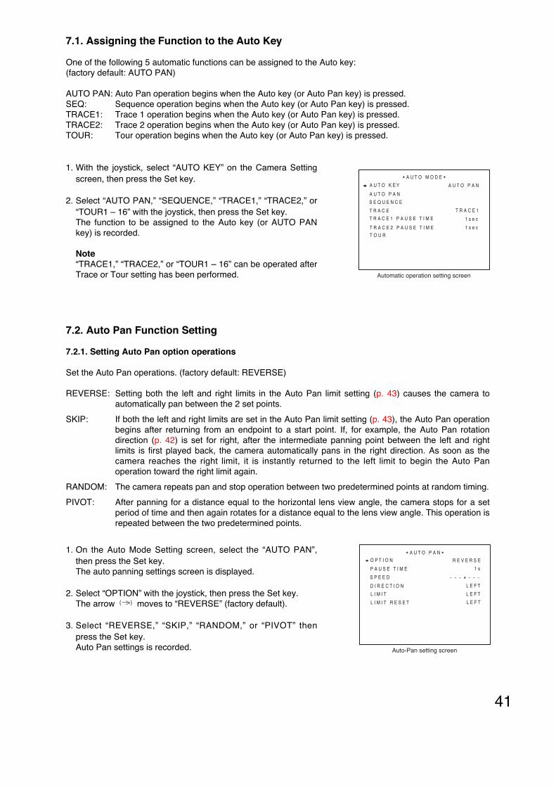
41
- - - - -
Auto-Pan setting screen
* A U T O P A N *O P T I O N
P A U S E T I M E
S P E E D
D I R E C T I O N
L I M I T
L I M I T R E S E T
R E V E R S E
1 s
L E F T
L E F T
L E F T
*-
7.1. Assigning the Function to the Auto Key
One of the following 5 automatic functions can be assigned to the Auto key: (factory default: AUTO PAN)
AUTO PAN: Auto Pan operation begins when the Auto key (or Auto Pan key) is pressed.SEQ: Sequence operation begins when the Auto key (or Auto Pan key) is pressed.TRACE1: Trace 1 operation begins when the Auto key (or Auto Pan key) is pressed.TRACE2: Trace 2 operation begins when the Auto key (or Auto Pan key) is pressed.TOUR: Tour operation begins when the Auto key (or Auto Pan key) is pressed.
1. With the joystick, select “AUTO KEY” on the Camera Settingscreen, then press the Set key.
2. Select “AUTO PAN,” “SEQUENCE,” “TRACE1,” “TRACE2,” or“TOUR1 – 16” with the joystick, then press the Set key.The function to be assigned to the Auto key (or AUTO PANkey) is recorded.
Note“TRACE1,” “TRACE2,” or “TOUR1 – 16” can be operated afterTrace or Tour setting has been performed. Automatic operation setting screen
A U T O K E Y
T R A C E
S E Q U E N C E
* A U T O M O D E *
T O U R
A U T O P A N
T R A C E 1 P A U S E T I M E
T R A C E 2 P A U S E T I M E
T R A C E 1
1 s e c
1 s e c
A U T O P A N
7.2. Auto Pan Function Setting
7.2.1. Setting Auto Pan option operations
Set the Auto Pan operations. (factory default: REVERSE)
REVERSE: Setting both the left and right limits in the Auto Pan limit setting (p. 43) causes the camera toautomatically pan between the 2 set points.
SKIP: If both the left and right limits are set in the Auto Pan limit setting (p. 43), the Auto Pan operationbegins after returning from an endpoint to a start point. If, for example, the Auto Pan rotationdirection (p. 42) is set for right, after the intermediate panning point between the left and rightlimits is first played back, the camera automatically pans in the right direction. As soon as thecamera reaches the right limit, it is instantly returned to the left limit to begin the Auto Panoperation toward the right limit again.
RANDOM: The camera repeats pan and stop operation between two predetermined points at random timing.
PIVOT: After panning for a distance equal to the horizontal lens view angle, the camera stops for a setperiod of time and then again rotates for a distance equal to the lens view angle. This operation isrepeated between the two predetermined points.
1. On the Auto Mode Setting screen, select the “AUTO PAN”,then press the Set key.The auto panning settings screen is displayed.
2. Select “OPTION” with the joystick, then press the Set key.The arrow moves to “REVERSE” (factory default).
3. Select “REVERSE,” “SKIP,” “RANDOM,” or “PIVOT” thenpress the Set key.Auto Pan settings is recorded.
( )

42
7.2.3. Auto Pan speed setting
Select the Auto Pan speed.
1. On the Auto Pan Mode Setting screen, select “SPEED” withthe joystick, then press the Set key.Auto Pan speed is recorded.
2. Move “*” at the appropriate position with the joystick, thenpress the Set key.This will record the Auto Pan speed.
NoteMoving “*” further to the right on the setting bar increases theAuto Pan speed setting. Speed setting screen
- - - - -
* A U T O P A N *O P T I O N
P A U S E T I M E
S P E E D
D I R E C T I O N
L I M I T
L I M I T R E S E T
R E V E R S E
1 s
L E F T
L E F T
L E F T
*-
S P E E D - - + - - -*
7.2.2. Setting the Auto Pan stop duration at an endpoint
The duration can be selected from 1s, 2s, 3s, 5s, 10s, 20s, and 30s. (Factory default: 1s)
1. On the Auto Pan Mode Setting screen, select “ PAUSE TIME”with the joystick, then press the Set key.The arrow moves to “1s” (factory default).
2. Select “1s,” “2s,” “3s,” “5s,” “10s,” “20s,” or “30s,” then pressthe Set key.Auto Pan stop duration at an endpoint is recorded.
( )
Pause time setting screen
- - - - -
* A U T O P A N *O P T I O N
P A U S E T I M E
S P E E D
D I R E C T I O N
L I M I T
L I M I T R E S E T
R E V E R S E
1 s
L E F T
L E F T
L E F T
*-
7.2.4. Setting the direction of Auto Pan rotation
When the direction of Auto Pan rotation is not set, the Auto Pan camera continues to rotate only in the one-way direction and is not reversed. When either the left or right limit or both limits are set, the direction set heremeans the direction in which the camera first moves. (Factory default: LEFT)
1. On the Auto Pan Mode Setting screen, select “DIRECTION”with the joystick, then press the Set key.
2. Select “LEFT” or “RIGHT” with the joystick, then press the Setkey.The direction of Auto Pan rotation is recorded.
Rotation direction setting screen
- - - - -
* A U T O P A N *O P T I O N
P A U S E T I M E
S P E E D
D I R E C T I O N
L I M I T
L I M I T R E S E T
R E V E R S E
1 s
L E F T
L E F T
L E F T
* +

43
Limit setting in progress screen
* * * - L E F T
L I M I T S E T T I N G
Limit setting screen
- - - - -
* A U T O P A N *O P T I O N
P A U S E T I M E
S P E E D
D I R E C T I O N
L I M I T
L I M I T R E S E T
R E V E R S E
1 s
L E F T
L E F T
L E F T
* +
[ When setting the limit location of Auto Pan rotation ]
1. On the Auto Pan Mode Setting screen, select “LIMIT” with thejoystick, then press the Set key.
2. Select “LEFT”, then press the Set key.The Limit Setting screen (left limit) is displayed.
NoteIn the Place of “***” on the Limit Setting screen, the cameranumber is displayed.
3. Set the desired angle of view with the joystick, zoom key andfocus key, then press the Set key.The left limit location of Auto Pan rotation is recorded.
3-1 When setting the right limit location as well
Select “RIGHT” with the joystick, then press the Set key.Since the Limit Setting screen (right limit) is displayed, setthe right limit location in the same way as Step 3 above.
3-2 When setting no right limit location
Exit the Camera Menu screen by pressing the menu startswitch or press CLEAR key on the Limit Setting Screen ofStep 3-1.
[ Deleting the set limit location of Auto Pan rotation ]
1. On the Auto Pan Mode Setting screen, select “LIMIT RESET”with the joystick, then press the Set key.
2. Select limit location to delete either “LEFT” or “RIGHT” with thejoystick, then press the Set key.
3. “LIMIT RESET OK?” appears, then press the Set key.The selected limit location will be deleted.
Limit reset screen
- - - - -
* A U T O P A N *O P T I O N
P A U S E T I M E
S P E E D
D I R E C T I O N
L I M I T
L I M I T R E S E T
R E V E R S E
1 s
L E F T
L E F T
L E F T
* +
7.2.5. Setting or deleting the Auto Pan limits
Set both the left and right limits of Auto Pan rotation.When only either the left or right limit is stored, the Auto Pan operation returns at a set point according to thesetting of the direction of Auto Pan rotation, that is, the camera is reversed for every 360° rotation. When thetilting position, zoom, and focus position differ between the left and right limits, data last set are stored. In thisevent, an intermediate panning point between both limits, and last set tilting position, zoom, and focus positionare first played back, and then the Auto Pan operation begins.

44
7.3.2. Setting the interval of sequential playback duration
Set the interval of sequential playback duration.The interval can be selected from “1s,” “2s,” “3s,” “5s,” “10s,” “20s,” and “30s.” (Factory default: 10s)
1. On the Auto Pan Mode Setting screen, select “SEQUENCE” with the joystick, then press the Set key.
2. On the Sequence Setting screen, select “STOP TIME”, then press the Set key.The arrow moves to “1s” (factory default).
3. Select “1s,” “2s,” “3s,” “5s,” “10s,” “20s,” or “30s” with the joystick, then press the Set key.The interval of sequential playback duration is recorded.
( )
Sequence setting screen
M O D E* S E Q U E N C E *
S T O P T I M E 1 0 s
N O R M A L
7.3. Setting the Sequence Function
7.3.1. Setting the sequential order
Sets the sequence order. (factory default: Normal)
NORMAL: Playbacks preset-memory stored camera positions in numerical order. The stop duration for eachposition and whether to skip the position depend on “Sequence Playback Duration Settings.”
RANDOM: Playbacks preset memory store camera positions in random order. The stop duration for eachposition is determined in random order.
TEST: Playbacks preset-memory stored camera positions in numerical order. The stop time for eachposition is set to 1 second and the sequence will be terminated after making a position circuit.
1. On the Auto Pan Mode Setting screen, select “SEQUENCE”with the joystick, then press the Set key.
2. On the Sequence Setting screen, select “MODE”, then pressthe Set key.The arrow moves to “Normal” (factory default).
3. Select “NORMAL,” “RANDOM,” or “TEST” with the joystick,then press the Set key. The sequence order is recorded.
( )
Auto-Pan mode setting screen
A U T O K E Y
T R A C E
S E Q U E N C E
* A U T O M O D E *
T O U R
A U T O P A N
T R A C E 1 P A U S E T I M E
T R A C E 2 P A U S E T I M E
T R A C E 1
1 s e c
1 s e c
A U T O P A N

45
Trace start location screen
T R A C E 1
S T A R T P O S I T I O N
Auto operation setting screen
A U T O K E Y
T R A C E
S E Q U E N C E
* A U T O M O D E *
T O U R
A U T O P A N
T R A C E 1 P A U S E T I M E
T R A C E 2 P A U S E T I M E
T R A C E 1
1 s e c
1 s e c
A U T O P A N
1. On the Auto Operation Setting screen, select “TRACE” withthe joystick, then press the Set key.
2. Select “TRACE1” or “TRACE2” with the joystick, then pressthe Set key.The Trace start location screen is displayed.
NoteSelect either “CLEAR1” or “CLEAR2” to delete the eachcorresponding trace operation.
3. Set the desired angle of view with the joystick, and zoom key,then press the Set key.The Trace Setting in progress screen is displayed, then storesthe joystick and zoom operations afterward.
Trace setting in progress screen
T R A C E 1
R E C
E V E N T : 2 5 5
7.4. Trace Function Setting
7.4.1. Storing the Trace operation
NoteUsing the rotation limit function after the trace operation has been stored into memory erases the traceoperation memory.

46
7.5. Setting the Trace Pause Time 1 and 2
When continuously playing back the trace operations with the Auto key (or Auto-Pan key), the stop durationinterval between start position and end position of one trace operations can be set. (Factory default: 1s)
1. On the Auto Operation Setting screen, select “TRACE1PAUSE TIME” or “TRACE2 PAUSE TIME” with the joystick,then press the Set key.
2. Select “1sec,” “2sec,” “3sec,” “5sec,” “10sec,” “20sec,” or“30sec” with the joystick, then press the Set key.The Trace pause time is recorded.
Auto operation setting screen
A U T O K E Y
T R A C E
S E Q U E N C E
* A U T O M O D E *
T O U R
A U T O P A N
T R A C E 1 P A U S E T I M E
T R A C E 2 P A U S E T I M E
T R A C E 1
1 s e c
1 s e c
A U T O P A N
Trace playback memory screen
T R A C E 1
R E P L A Y
M E M O R Y
4. Press the Set key on Trace Setting in progress screen.“REPLAY” and “MEMORY” screen is displayed.
4-1 When “REPLAY” is selectedConfirms the stored trace.
4-2 When “MEMORY” is selectedSets the trace function.
NoteTrace can be set after above Step 4 – 2 procedure has beenperformed on trace playback and memory screens.
[ Deleting the trace operation memory ]Select “CLEAR1” or “CLEAR2” in the same way as “Trace Function setting” Step 3 (p. 45) to delete eachcorresponding trace operation.
[ Storing the trace operation over again ]Follow Step 1 – 4 again after deleting the trace operation in the above way.
Notes• The stored trace operation may slightly differ from the actual played back image on the monitor. To avoid
this, select a wider angle of view than you wish, and slowly operate camera movements during the traceoperation memory.
• To ensure the reproduction performance, the manual operation speed is limited during trace operation.

47
7.6. Tour Setting
7.6.1. Tour programming
Set the operation to be programmed to each Tour Nos. 1 – 16.
1. On the Auto Operation Setting screen, select “TOUR” with thejoystick, then press the Set key.
2. On the Tour Number Selection screen, select the number tobe programmed with the joystick, then press the Set key.
3. On the Tour setting screen, select “ORDER” with the joystick,then press the Set key.
4. Select the number to be set, then press the Set key.
5. Select the setting items with the joystick, then press the Setkey.Choices are as follows.
***POS: Performs preset playback.AUX1 ON, AUX1 OFF: Gates auxiliary contact.AUX2 ON, AUX2 OFF: Gates auxiliary contact.TOUR1 – 16: Executes the program of other tour.TRACE1, TRACE2: Executes the trace.B/W ON, B/W OFF: Switches to Black & White mode or release it.STOP: Stops tour.
NoteAUX2 : C-CC564 and C-CC574 onlyB/W ON, B/W OFF : C-CC564, C-CC574, C-CC764 and C-CC774 only
Auto operation setting screen
A U T O K E Y
T R A C E
S E Q U E N C E
* A U T O M O D E *
T O U R
A U T O P A N
T R A C E 1 P A U S E T I M E
T R A C E 2 P A U S E T I M E
T R A C E 1
1 s e c
1 s e c
A U T O P A N
Tour number selection screen
1 : e n t r a n c e
2 : w - e x i t 3 : e - e x i t
4 : x
6 : o
5 : x
7 : o
8 : o
1 0 : x1 1 : x
1 2 : x
1 4 : x
1 3 : x
1 5 : x
1 6 : x
* T O U R *9 : o
Tour setting screen
* TOUR 1 S E T T I N G *O R D E R I N S E R T R E S E T
1 : * * 1 P O S S P 1 2 0 1 0 s e c
2 : * * 2 P O S S P 2 4 3 s e c
3 : * * 3 P O S S P 1 6 0 5 s e c
4 : * * 4 P O S S P 1 2 0 1 0 s e c5 : T R A C E 1 1 T I M E
6 : * * * P O S S P * * * * * s e c
7 : * * * P O S S P * * * * * s e c
8 : * * * P O S S P * * * * * s e c
N E X T P A G E

48
NoteWhen selecting preset playback, select “***POS” with the joystick, enter the position number, then pressthe Set key.
Choice Selected contents 1
***POS SPA / SP8 / SP16 / SP24 /SP40 / SP60 / SP90 / SP120 /SP160 / SP240 / SP360
1sec / 2sec / 3sec / 5sec / 10sec / 20sec / 30sec
TRACE 1 / TRACE 2
1TIME / 2TIME / 3TIME / 4TIME / 5TIME
1TIME / 2TIME / 3TIME / 4TIME / 5TIME
B/W ON / B/W OFF
AUX1 ON / AUX1 OFF /AUX2 ON / AUX2 OFF
TOUR 1 – 16
STOP
Note: For the details of choice and contents, refer to Step 5-1 afterward.
Selected contents 2
5-1 When preset playback “***POS” is selected
(1) Enter the position number with the numerical keypad, then press the Set key. Pressing the Set key againconfirms the number.
(2) Select the preset transfer speed of Pan and Tilt from “SPA,” “SP8,” “SP16,” “SP24,” “SP40,” “SP60,”“SP90,” “SP120,” “SP240,” or “SP360” with the joystick, then press the Set key.
NoteThe figure represents the maximum speed of Pan and Tilt (rotation angle per second) when performingthe preset transfer.“A”: Operates at a constant speed of “25” without acceleration or deceleration.
(3) Select the stop duration after preset playback completion from “1sec,” “2sec,” “3sec,” “5sec,” “10sec,”“20sec,” or “30sec” with the joystick, then press the Set key. This will record the program.
5-2 When “TRACE” or “TOUR” is selected
(1) Select the repeat times of Trace or Tour from “Once” – “5 times” with the joystick, then press the Set key.This will record the program.
5-3 When “AUX ON,” “AUX OFF,” “B/W ON,” “B/ W OFF,” or “STOP” is selected
This will record the program.
6. Programming all desired operations to be set in the selected tour number completes the settings.

49
Tour number selection screen
1 : e n t r a n c e
2 : w - e x i t 3 : e - e x i t
4 : x
6 : o
5 : x
7 : o
8 : o
1 0 : x1 1 : x
1 2 : x
1 4 : x
1 3 : x
1 5 : x
1 6 : x
* T O U R *9 : o
Tour setting screen
* TOUR 1 S E T T I N G *O R D E R I N S E R T R E S E T
1 : * * 1 P O S S P 1 2 0 1 0 s e c
2 : * * 2 P O S S P 2 4 3 s e c
3 : * * 3 P O S S P 1 6 0 5 s e c
4 : * * 4 P O S S P 1 2 0 1 0 s e c5 : T R A C E 1 1 T I M E
6 : * * * P O S S P * * * * * s e c
7 : * * * P O S S P * * * * * s e c
8 : * * * P O S S P * * * * * s e c
N E X T P A G E
7.6.2. Inserting operation into Tour program
Add the program into the set tour.
1. On the Auto Operation Setting screen, select “TOUR” with thejoystick, then press the Set key.
2. On the Tour Number Selection screen, select the tour numberto be programmed with the joystick, then press the Set key.
3. On the Tour Setting screen, select “INSERT” with the joystick,then press the Set key.
4. Select the number to be inserted, then press the Set key.New Tour is inserted at one place before the selected number. Set the program in the same way as Tour Programming (p. 47)Step 4 afterward.
Auto operation setting screen
A U T O K E Y
T R A C E
S E Q U E N C E
* A U T O M O D E *
T O U R
A U T O P A N
T R A C E 1 P A U S E T I M E
T R A C E 2 P A U S E T I M E
T R A C E 1
1 s e c
1 s e c
A U T O P A N

50
7.6.3. Deleting Tour program
1. On the Auto Operation Setting screen, select “TOUR” with thejoystick, then press the Set key.
2. On the Tour Number Selection screen, select the tour numberto be programmed with the joystick, then press the Set key.
3. On the Tour Setting screen, select “RESET” with the joystick,then press the Set key.
4. Select the number to be deleted, then press the Set key.Tour program is deleted.
Tour number selection screen
1 : e n t r a n c e
2 : w - e x i t 3 : e - e x i t
4 : x
6 : o
5 : x
7 : o
8 : o
1 0 : x1 1 : x
1 2 : x
1 4 : x
1 3 : x
1 5 : x
1 6 : x
* T O U R *9 : o
Auto operation setting screen
A U T O K E Y
T R A C E
S E Q U E N C E
* A U T O M O D E *
T O U R
A U T O P A N
T R A C E 1 P A U S E T I M E
T R A C E 2 P A U S E T I M E
T R A C E 1
1 s e c
1 s e c
A U T O P A N
Tour setting screen
* TOUR 1 S E T T I N G *O R D E R I N S E R T R E S E T
1 : * * 1 P O S S P 1 2 0 1 0 s e c
2 : * * 2 P O S S P 2 4 3 s e c
3 : * * 3 P O S S P 1 6 0 5 s e c
4 : * * 4 P O S S P 1 2 0 1 0 s e c5 : T R A C E 1 1 T I M E
6 : * * * P O S S P * * * * * s e c
7 : * * * P O S S P * * * * * s e c
8 : * * * P O S S P * * * * * s e c
N E X T P A G E

51
8. ALARM SETTINGS
The camera is equipped with alarm contact inputs. When an alarm signal is detected across the two contactsand the alarm is activated, if the ID display has been set to ON, the set ID is displayed on the screen, causingan alarm to operate according to the following settings. When multiple alarms are simultaneously activated,the most recent alarm takes precedence in playback.
Notes• The number of alarm contact inputs differs depending on the model. Refer to the following.
3 Contact inputs: C-CC514, C-CC714, C-CC764, C-CC774 8 Contact inputs: C-CC564, C-CC574
• When assigning the C-RM500’s camera alarm and camera alarm preset functions to the unit alarm contactinputs, refer below to set.
INPUT: ON REPORT: ON ACTIVE: CLOSE or OPENPRIORITY: ALARM ACTION: OFFTIME: Put the clock right to the C-RM500’s alarm time settings RESET ACTION: OFF
• The alarm can also be activated by setting “Action” Alarms 1–8 of the Motion Detection setting item, otherthan alarm input terminals (refer to p. 76). The following table shows the number of inputs and settings foreach camera. The number of the alarm input terminal matches the number of the setting item.
8.1. Input Setting
Of alarm inputs, designate the input number to which an alarm signal is actually connected. Unless the alarminput settings are performed, alarm is not activated even if the alarm signal is received.
1. On the Camera Menu screen, select “ALARM”, then press the Set key.
C A M
C A M E R A M E N U
P R E S E T
I D S E T T I N G
C A M E R A S E T T I N G
A U T O M O D E
A L A R M
A U X
T I M E R
M A N U A L
M A I N T E N A N C E
Camera menu screen
E N G L I S HL A N G U A G E
I N P U T* A L A R M *
R E P O R T
A C T I V E S T A T E
P R I O R I T Y
A C T I O N
I N T E R V A L
R E S E T A C T I O NA L A R M D A T A
Alarm setting screen
2. On the Alarm Settings screen, select “INPUT”, then press the Set key.
3. On the Alarm Input Setting screen, select the number, thenpress the Set key.
C-CC564, C-CC574
No. of alarminput terminals
Motion detection–action
8 8
3 8
3 0
No. of alarmsetting items
8
8
3
Model Number
C-CC764, C-CC774
C-CC514, C-CC714
Input Method Setting

52
8.2. Report Setting
Specify the terminal that transmits alarm input information to the controller.
1. On the Alarm Setting screen, select “REPORT”, then press theSet key.
2. On the Alarm Setting screen, select the number, then pressthe Set key.
3. Select “ON” with the joystick, then press the Set key to enabletransmission of alarm input information.
4. Repeat Step 2, 3 to turn the all numbers to which alarm signalis transmitted “ON.”
Alarm report setting screen
* A L A R M *R E P O R T
- - - - - - - - - - - - - - - - - - - - - - - - - - -
1 : O N
2 : O N3 : O F F
4 : O F F
6 : O F F
5 : O F F
7 : O F F
8 : O F F
Alarm setting screen
I N P U T* A L A R M *
R E P O R T
A C T I V E S T A T E
P R I O R I T Y
A C T I O N
I N T E R V A L
R E S E T A C T I O NA L A R M D A T A
4. Select “ON” with the joystick, then press the Set key to enablealarm reception.
Note: Set to “OFF” when disabling alarm reception.
5. Repeat Step 3, 4 to turn the all numbers to which alarm signalis input “ON.”
Alarm input setting screen
* A L A R M *I N P U T
- - - - - - - - - - - - - - - - - - - - - - - - - - -
1 : O N
2 : O N3 : O F F
4 : O F F
6 : O F F
5 : O F F
7 : O F F
8 : O F F

53
Alarm setting screen
I N P U T* A L A R M *
R E P O R T
A C T I V E S T A T E
P R I O R I T Y
A C T I O N
I N T E R V A L
R E S E T A C T I O NA L A R M D A T A
8.4. Priority Setting
Specify whether to display the set alarm ID on the screen and forcibly execute alarm operation or give priorityto operation when an alarm signal is received.
Alarm: Ignores commands from the controller and starts alarm operation.
Manual: Initiates alarm operation only while operating the initial program.
Timer: Initiates alarm operation after the preset time elapses. When the initial program is operating, alarmoperations are initiated immediately.
1. On the Alarm Setting screen, select “PRIORITY”, then pressthe Set key.
2. On the Alarm Priority Setting screen, select the number, thenpress the Set key.
3. Select “ALARM,” “MANUAL,” or “TIMER” with the joystick,then press the Set key to confirm the priority function settings.
3-1 When “ALARM,” or “MANUAL” is selected
Priority function settings are recorded.
3-2 When “Timer” is selected
Select the preset time before alarm operation initiation from“3sec,” “5sec,” “10sec,” “15sec,” “20sec,” “30sec,” “45sec,” or“1min” and press the Set key to confirm the priority functionsettings.
4. Repeat Step 2, 3 to perform priority function settings of alarminputs to be used.
Alarm priority setting screen
* A L A R M *A C T I V E S T A T E
- - - - - - - - - - - - - - - - - - - - - - - - - - -
1 : A L A R M
2 : T I M E R 3 s e c3 : A L A R M
4 : A L A R M
6 : A L A R M
5 : A L A R M
7 : A L A R M
8 : A L A R M
Alarm active setting screen
* A L A R M *A C T I V E S T A T E
- - - - - - - - - - - - - - - - - - - - - - - - - - -
1 : C L O S E
2 : O P E N3 : C L O S E
4 : C L O S E
6 : C L O S E
5 : C L O S E
7 : C L O S E
8 : C L O S E
8.3. Active Level Setting
Specify whether to receive alarm signal information with make or break contact.
1. On the Alarm Setting screen, select “ACTIVE STATE”, thenpress the Set key.
2. On the Alarm Active Setting screen, select the number, thenpress the Set key.
3. Select “CLOSE” or “OPEN” with the joystick, then press theSet key to determine the alarm signal reception condition.
4. Repeat Step 2, 3 to perform Active Level setting in accordancewith the alarm signal reception condition.
Alarm setting screen
I N P U T* A L A R M *
R E P O R T
A C T I V E S T A T E
P R I O R I T Y
A C T I O N
I N T E R V A L
R E S E T A C T I O NA L A R M D A T A

54
8.5. Operation (Action) Setting
Specify the camera’s operation (Action) when an alarm signal is received.
NoteThe camera’s alarm function, and the C-RM500 Controller’s camera alarm function and camera alarm presetfunction are operated independently, and cannot be used together. Also, the C-RM500’s alarm hold functioncannot be used to hold alarm operation.To enable the camera’s alarm operation function, set the C-RM500’s Camera Alarm Settings to OFF.
1. On the Alarm Setting screen, select “ACTION”, then press theSet key.
2. On the Alarm Action Setting screen, select the number, thenpress the Set key.
3. Select “OFF,” “***POS,” “TOUR1 – 16,” “AUX1 ON,” “AUX2ON,” “AUX1 OFF,” “AUX2 OFF,” “TRACE1,” “TRACE2,” or“HOME” with the joystick, then press the Set key.
3-1 When item other than “***POS” is selected
Selecting the items other than “***POS” records cameraoperation (Action).
3-2 When “***POS” is selected
3-2-1 Enter the position number with numerical keypad, thenpress the Set key.
3-2-2 Pressing the Set key displays the selected positionnumber on the monitor screen.
4. Repeat Step 2, 3 to record the camera operation corresponding to each receiving input number.
NoteAUX2 : C-CC564 and C-CC574 only
Alarm setting screen
I N P U T* A L A R M *
R E P O R T
A C T I V E S T A T E
P R I O R I T Y
A C T I O N
I N T E R V A L
R E S E T A C T I O NA L A R M D A T A
Alarm action setting screen
* A L A R M *A C T I O N
- - - - - - - - - - - - - - - - - - - - - - - - - - -
1 : O F F
2 : T R A C E 13 : O F F
4 : O F F
6 : O F F
5 : O F F
7 : O F F
8 : O F F

55
8.6. Clock Setting
Specify the period of time that alarm conditions are maintained when an alarm signal is received.
1. On the Alarm Setting screen, select “INTERVAL”, then pressthe Set key.
2. On the Alarm Clock Setting screen, select the number, thenpress the Set key.
3. Select “3sec,” “5sec,” “10sec,” “15sec,” “20sec,” “30sec,”“45sec,” “1min,” “3min,” “5min,” or “Level” with the joystick,then press the Set key to confirm the duration that alarmconditions are maintained.When the Alarm Report is set to ON, pressing the Set keytransmits the alarm input signal for the preset period of time tothe controller.
NoteLevel will continue alarm status during alarm signal reception.
4. Repeat Step 2, 3 to perform duration settings.
Alarm setting screen
I N P U T* A L A R M *
R E P O R T
A C T I V E S T A T E
P R I O R I T Y
A C T I O N
I N T E R V A L
R E S E T A C T I O NA L A R M D A T A
Alarm clock setting screen
* A L A R M *I N T E R V A L
- - - - - - - - - - - - - - - - - - - - - - - - - - -
1 : 2 0 s e c
2 : 5 s e c3 : 2 0 s e c
4 : 2 0 s e c
6 : 2 0 s e c
5 : 2 0 s e c
7 : 2 0 s e c
8 : 2 0 s e c

56
8.7. Reset Operation (Action) Setting
Specify the camera’s operation when alarm conditions are reset.
NoteThe camera’s alarm reset operation function, and the C-RM500 Controller’s camera alarm function andcamera alarm preset function are operated independently, and cannot be used together. Also, the C-RM500’salarm hold function cannot be used to hold alarm reset operation.To enable the camera’s alarm operation function, set the C-RM500’s Camera Alarm Settings to OFF.
1. On the Alarm Setting screen, select “RESET ACTION,” thenpress the Set key.
2. On the Alarm Reset Operation Setting screen, select thenumber, then press the Set key.
3. Select “OFF,” “***POS,” “TOUR1 – 16,” “AUX1 ON,” “AUX2ON,” “AUX1 OFF,” “AUX2 OFF,” “TRACE1,” “TRACE2,” or“HOME” with the joystick, then press the Set key.
3-1 When item other than “***POS” is selected
Selecting the items other than “***POS” record cameraoperation (Action).
3-2 When “***POS” is selected
3-2-1 Enter the position number with numerical keypad, thenpress the Set key.
3-2-2 Pressing the Set key displays the selected positionnumber on the monitor screen.
4. Repeat Step2, 3 to record the camera operationcorresponding to each receiving input number.
NoteAUX2 : C-CC564 and C-CC574 only
Alarm setting screen
I N P U T* A L A R M *
R E P O R T
A C T I V E S T A T E
P R I O R I T Y
A C T I O N
I N T E R V A L
R E S E T A C T I O NA L A R M D A T A
Alarm reset operation setting screen
* A L A R M *R E S E T A C T I O N
- - - - - - - - - - - - - - - - - - - - - - - - - - -
1 : 3 P O S
2 : T R A C E 13 : T O U R 1
4 : 3 2 P O S
6 : O F F
5 : O F F
7 : O F F
8 : O F F

57
8.8. Verifying Alarm Logs (Alarm Data)
1. Select “ALARM DATA” on the Alarm Setting screen, thenpress the Set key.
2. Search the log number to be confirmed on the alarm logscreen.
NoteAlarm log recorded most recently takes precedence.Up to 16 latest logs can be displayed.
I N P U T* A L A R M *
R E P O R T
A C T I V E S T A T E
P R I O R I T Y
A C T I O N
I N T E R V A L
R E S E T A C T I O NA L A R M D A T A
Alarm setting screen
* A L A R M *A L A R M D A T A
- - - - - - - - - - - - - - - - - - - - - - - - - - -
1 : M M / D D / Y Y A 1
2 : 3 :
4 :
6 :
5 :
7 :
8 :
Alarm log screen

58
9. CONTACT OUTPUT SETTINGS
Camera built-in contact outputs can be controlled by the controller.
9.1. AUX1 Setting
The AUX1 is an open collector type contact. The controller’s auxiliary switch is used to control it.
1. Select “AUX” on the Camera Menu screen, then press the Setkey.
2. Select “AUX1” on the AUX (Contact Output Setting) screen,then press the Set key.
3. Select “INITIAL STATE” on AUX1 Setting screen, then pressthe Set key.
4. Select “ON” or “OFF” with the joystick, then press the Set key.When the initializing operation has been terminated after thepower had been turned on, set the AUX1 to ON (valid) or OFF(invalid).
5. Select “ON STATE” on the AUX1 Setting screen, then pressthe Set key.
6. Select “CLOSE” or “OPEN” with the joystick, then press theSet key.Set the contact whether to Close or Open when it is turnedON.
7. Do not change setting of “TYPE” on the AUX1 Setting screen.
NoteDo not set types other than Momentary (factory default). If changed, AUX1 does not operate correctly.
8. Select “ON TIME” on the AUX1 Setting screen, then press the Set key.
9. Select “NO LIMIT,” “1sec,” “2sec,” “3sec,” “5sec,” “10sec,” “20sec,”or “30sec” with the joystick, then pressthe Set key to set the duration that the contact is maintained ON.
NO LIMIT:Maintained to be ON until it is turned OFF
“1sec,” “2sec,” “3sec,” “5sec,” “10sec,” “20sec,” “30sec”:Contact is maintained ON for the preset duration.
C A M
C A M E R A M E N U
P R E S E T
I D S E T T I N G
C A M E R A S E T T I N G
A U T O M O D E
A L A R M
A U X
T I M E R
M A N U A L
M A I N T E N A N C E
Camera menu screen
E N G L I S HL A N G U A G E
* A U X *- - - - - - - - - - - - - - - - - - - - - - - - - - -
A U X 1A U X 2
AUX (Contact output setting) screen
* A U X *A U X 1
- - - - - - - - - - - - - - - - - - - - - - - - - - -
I N I T I A L S T A T E
O N S T A T E
T Y P E
O N T I M E
O F F
C L O S E
M O M E N T A R Y
N O L I M I T
AUX 1 (Contact output 1) setting screen

59
9.2. AUX2 Setting (C-CC564 and C-CC574 only)
The AUX2 is a relay type contact. The controller’s defroster switch is used to control it.
1. Select “AUX2” on the AUX (Contact Output Setting) screen,then press the Set key.
2. Do not change setting of “Type” on the AUX2 Setting screen.
NoteDo not set types other than Momentary (factory default). Ifchanged, AUX2 does not operate correctly.
3. Select “ON TIME” in the AUX2 Setting screen, then press theSet key.
4. Select “NO LIMIT,” “1sec,” “2sec,” “3sec,” “5sec,” “10sec,”“20sec,”or “30sec” with the joystick, then press the Set key toset the duration that the contact is maintained ON.
NO LIMIT:Maintained to be ON until it is turned OFF
“1sec,” “2sec,” “3sec,” “5sec,” “10sec,” “20sec,” “30sec”:Contact is maintained ON for the preset duration after receiptof ON instruction.
* A U X *- - - - - - - - - - - - - - - - - - - - - - - - - - -
A U X 1A U X 2
AUX setting screen
* A U X *A U X 2
- - - - - - - - - - - - - - - - - - - - - - - - - - -
T Y P E
O N T I M E
M O M E N T A R Y
N O L I M I T
AUX 2 setting screen
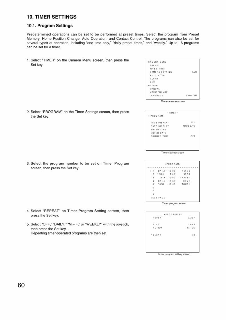
60
10. TIMER SETTINGS
10.1. Program Settings
Predetermined operations can be set to be performed at preset times. Select the program from PresetMemory, Home Position Change, Auto Operation, and Contact Control. The programs can also be set forseveral types of operation, including “one time only,” “daily preset times,” and “weekly.” Up to 16 programscan be set for a timer.
1. Select “TIMER” on the Camera Menu screen, then press theSet key.
2. Select “PROGRAM” on the Timer Settings screen, then pressthe Set key.
3. Select the program number to be set on Timer Programscreen, then press the Set key.
4. Select “REPEAT” on Timer Program Setting screen, thenpress the Set key.
5. Select “OFF,” “DAILY,” “M – F,” or “WEEKLY” with the joystick,then press the Set key. Repeating timer-operated programs are then set.
C A M
C A M E R A M E N U
P R E S E T
I D S E T T I N G
C A M E R A S E T T I N G
A U T O M O D E
A L A R M
A U X
T I M E R
M A N U A L
M A I N T E N A N C E
Camera menu screen
E N G L I S HL A N G U A G E
P R O G R A M* T I M E R *
T I M E D I S P L A Y
D A T E D I S P L A Y
E N T E R T I M E
E N T E R D A T E
S U M M E R T I M E
1 2 H
M M / D D / Y Y
O F F
Timer setting screen
- - - - - - - - - - - - - - - - - - - - - - - - - - -
* P R O G R A M *
1 D A I L Y 1 8 : 0 0 1 5 P O S
2 1 2 / 2 0 7 : 0 0 3 P O S
3 M - F 1 2 : 0 0 T R A C E 1
4 D A I L Y 1 0 : 3 0 H O M E5 F r i / W 1 5 : 0 0 T O U R 1
6
7
8
N E X T P A G E
Timer program screen
* P R O G R A M 1 *
T I M E
A C T I O N
R E P E A T
C L E A R
D A I L Y
1 8 : 0 0
1 5 P O S
N O
Timer program setting screen

61
5-1 When OFF is selected
(1) Select “DATE” and press the Set key.(2) Enter the month with Numerical keypad and press the Set key.(3) Press the Set key to set the month.
Similarly, set last 2 digits for day and year.
NoteThe display formats of Month /Day/ Year or Day/ Month/ Year follows the date display setting.
5-2 When WEEKLY is selected
(1) Select “DATE” and press the Set key.(2) Select a day of the week from “SUN” to “SAT”, then press the Set key.
6. Select “TIME” on the Program Setting screen, the press the Set key.
6-1 Enter the time with Numerical keypad and press the Set key.
6-2 Press the Set key to set the time.Similarly, set the minute.
7. Select “***POS” on the Program Setting screen, then press the Set key.
8. Select “***POS,” “TOUR1 – 16,” “AUX1 ON,” “AUX2 ON,” “AUX1 OFF,” “AUX2 OFF,” “TRACE1,”“TRACE2,” or “HOME” with the joystick, then press the Set key.
8-1 When setting “***POS”
(1) Select “***POS” with the joystick, designate the number with the Numerical keypad and press the Set key.(2) Press the Set key to set the action.
8-2 When setting “AUX1 ON,” “AUX1 OFF,” “AUX2 ON,” “AUX2 OFF,” “TRACE1,” “TRACE2” and “TOUR1 – 16”
(1) Select the desired item from the above, then press the Set key.(2) Press the Set key to set the action.
8-3 When setting “Home”
(1) Select “HOME” with the joystick, then press the Set key.(2) Select “1POS,” “2POS,” “254POS,” “255POS,” “AUTO PAN,” “SEQUENCE,” “TRACE1,” “TRACE2,” or
“TOUR1 – 16” with the joystick, then press the Set key.Press the Set key to set the action.
NoteWhen the “Home” has been set, the home operation can be changed at the preset time.
NoteAUX2 : C-CC564 and C-CC574 only

62
10.1.1. Erasing Timer program
1. Select “PROGRAM” on the Timer Setting screen, press theSet key.
2. Select the program number to be erased on program screen,then press the Set key.
3. Select “CLEAR” on the Program Setting screen, then pressthe Set key.
4. Select “YES” with the joystick, then press the Set key. Pressing the Set key erases the timer program.
- - - - - - - - - - - - - - - - - - - - - - - - - - -
* P R O G R A M *
1 D A I L Y 1 8 : 0 0 1 5 P O S
2 1 2 / 2 0 7 : 0 0 3 P O S
3 M - F 1 2 : 0 0 T R A C E 1
4 D A I L Y 1 0 : 3 0 H O M E5 F r i / W 1 5 : 0 0 T O U R 1
6
7
8
N E X T P A G E
Timer program screen
* P R O G R A M 1 *
T I M E
A C T I O N
R E P E A T
C L E A R
D A I L Y
1 8 : 0 0
1 5 P O S
N O
Timer program setting screen
P R O G R A M* T I M E R *
T I M E D I S P L A Y
D A T E D I S P L A Y
E N T E R T I M E
E N T E R D A T E
S U M M E R T I M E
1 2 H
M M / D D / Y Y
O F F
Timer setting screen

63
10.3. Date Display Setting
The date display can be set for month/ day /year, day/ month/ year or year/ month/ day display formats.
1. Select “DATE DISPLAY” on the Timer Setting screen, thenpress the Set key.
2. Select “MM/ DD/ YY,” “DD/ MM/ YY,” or “YY/ MM/ DD” with thejoystick, then press the Set key.Pressing the Set key sets the date display format.
Note: MM: month, DD: date, YY: year
P R O G R A M* T I M E R *
T I M E D I S P L A Y
D A T E D I S P L A Y
E N T E R T I M E
E N T E R D A T E
S U M M E R T I M E
1 2 H
M M / D D / Y Y
O F F
Timer setting screen
10.2. Time Display Selection
The time display can be set to 12-hour or 24-hour display formats.
1. Select “TIME DISPLAY” on the Timer Setting screen, thenpress the Set key.
2. Select “12H” or “24H”with the joystick, then press the Set key.Pressing the Set key sets the timer display format.
P R O G R A M* T I M E R *
T I M E D I S P L A Y
D A T E D I S P L A Y
E N T E R T I M E
E N T E R D A T E
S U M M E R T I M E
1 2 H
M M / D D / Y Y
O F F
Timer setting screen

64
10.5. Setting the Date
1. Select “ENTER DATE” on the Timer Setting screen, thenpress the Set key.
2. Enter the month figures with Numerical keypad, then press theSet key.The arrow moves to “Date.”
3. Repeat Step 2 to set month/date/year.
NoteThe display formats of Month/ Day/ Year or Day/ Month/ Yearfollows the date display setting.
( )
* T I M E R *E N T E R D A T E
0 1 / 2 5 / 0 4
Date setting screen
P R O G R A M* T I M E R *
T I M E D I S P L A Y
D A T E D I S P L A Y
E N T E R T I M E
E N T E R D A T E
S U M M E R T I M E
1 2 H
M M / D D / Y Y
O F F
Timer setting screen
10.4. Setting the Timer
1. Select “ENTER TIME” on the Timer Setting screen, then pressthe Set key.
2. Enter the time figures with Numerical keypad, then press theSet key.Pressing the Set key sets the time and the arrow movesto “minutes.”
3. Repeat Step 2 to set the minute.
4. When the arrow moves to “second”, press the Set key.“Second” indication is cleared to 00 and the time is set.
Note: Time can be set in the order of hour/ minute/ second.
( )
( )
* T I M E R *E N T E R T I M E
1 5 : 2 6 : 2 7
Time setting (Enter time) screen
P R O G R A M* T I M E R *
T I M E D I S P L A Y
D A T E D I S P L A Y
E N T E R T I M E
E N T E R D A T E
S U M M E R T I M E
1 2 H
M M / D D / Y Y
O F F
Timer setting screen

65
10.6. Setting the Summer Time (Daylight saving time)
Enables summer time between 2:00 AM on the set first day of summer time and 2:00 AM on the last day.
OFF: Disables summer time.ON: Enables summer time.SET: Performs summer time setting.
1. On the Timer Setting screen, select “SUMMER TIME”, thenpress the Set key.
2. Select “OFF,” “ON,” or “SET” with the joystick, then press theSet key.
2-1 When “ON,” or “OFF” is selected
Selecting “ON” or “OFF” terminates Summer time enable/disable settings.
2-2 When “SET” is selected
(1) Select either “FIRST DAY” or “LAST DAY” with the joystick,then press the Set key.The arrow moves to “Month.”
(2) Select “Month” with the joystick, then press the Set key.The arrow moves to “Week.”
(3) Select “Week” with the joystick, then press the Set key.Pressing the Set key sets the first day or the last day of thesummer time.
( )
( )
P R O G R A M* T I M E R *
T I M E D I S P L A Y
D A T E D I S P L A Y
E N T E R T I M E
E N T E R D A T E
S U M M E R T I M E
1 2 H
M M / D D / Y Y
O F F
Summer time setting screen
* T I M E R *S U M M E R T I M E S E T T I N G
F I R S T D A Y
L A S T D A Y1 S T S U N
1 S T S U NJ A N
J A N
Summer time setting screen

66
11. MANUAL SETTINGS
11.1. Resetting Zoom Interlocking
Rotation speed relative to zoom ratio can be set to OFF. Select OFF when the function of reducing therotation speed during telescopic operation is not needed.
1. Select “MANUAL” on the Camera Menu screen, then press theSet key.
2. Select “ZOOM SCALABLE P/T” on the Manual Settingsscreen, then press the Set key.
3. Select “ON” or “OFF” with the joystick, then press the Set key.Pressing the Set key sets the Zoom Interlocking function status.
C A M
C A M E R A M E N U
P R E S E T
I D S E T T I N G
C A M E R A S E T T I N G
A U T O M O D E
A L A R M
A U X
T I M E R
M A N U A L
M A I N T E N A N C E
Camera menu screen
E N G L I S HL A N G U A G E
Z O O M S C A L A B L E P / T
M A X P / T S P E E D
P / T L I M I T S E T T I N G
* M A N U A L *
P / T L I M I T
F L I P
U P L I M I T
1 2 0
O F F
O N
O F F
L E F T
O N
Manual setting screen
11.2. Rotation Limit Selection
Designate the pan and tilt rotation range limits.
OFF: Disables rotation limits.ON: Enables rotation limits. The camera does not tilt between –90° and –185°.CLEAR: Deletes all rotation limit positions.
Notes• Enabling the rotation limit sets the tilt range to between +5° and –185°. The auto-flip function is
automatically disabled.• Enabling the rotation limit cancels the trace setting.
1. Select “P/T LIMIT” on the Manual Setting screen, then pressthe Set key.
2. Select “OFF,” “ON,” or “CLEAR ” with the joystick, then pressthe Set key.Pressing the Set key sets the Rotation Limit status.
Z O O M S C A L A B L E P / T
M A X P / T S P E E D
P / T L I M I T S E T T I N G
* M A N U A L *
P / T L I M I T
F L I P
U P L I M I T
1 2 0
O F F
O N
O F F
L E F T
O N
Manual setting screen

67
11.3. Rotation Limit Setting
Set the pan and tilt rotation range.
1. Select “P/T LIMIT SETTING” on the Manual Setting screen,then press the Set key.
2. Select “LEFT,” “RIGHT,” “UP,” or “DOWN” with the joystick,then press the Set key.Pressing the Set key sets the direction of rotation range to be set.
3. Tilt the joystick left or right to set the limit orientation to “LEFT”or “RIGHT” and upward or downward to set “UP” or “DOWN”,then press the Set key.
4. Repeat Step 2, 3 to perform settings for all directions.The rotation limit can be set.
Z O O M S C A L A B L E P / T
M A X P / T S P E E D
P / T L I M I T S E T T I N G
* M A N U A L *
P / T L I M I T
F L I P
U P L I M I T
1 2 0
O F F
O N
O F F
L E F T
O N
Manual setting screen
P / T L I M I T S E T T I N G* * * - L E F T
Rotation limit (left) setting screen
11.4. Manual Speed Setting
Set the maximum speed of panning and tilt in manual operation.
1. Select “MAX P/T SPEED” on the Manual Setting screen, thenpress the Set key.
2. Select “A,” “8,” “16,” “24,” “40,” “60,” “90,” “120,” “160,” “240,”or “360”, then press the Set key.Pressing the Set key sets the maximum speed in manualoperation.
NoteThe larger the figure is, the faster pan and tilt speeds.“A” : Operates at a constant speed of “25” without accelerationor deceleration.
Z O O M S C A L A B L E P / T
M A X P / T S P E E D
P / T L I M I T S E T T I N G
* M A N U A L *
P / T L I M I T
F L I P
U P L I M I T
1 2 0
O F F
O N
O F F
L E F T
O N
Manual setting screen

68
Z O O M S C A L A B L E P / T
M A X P / T S P E E D
P / T L I M I T S E T T I N G
* M A N U A L *
P / T L I M I T
F L I P
U P L I M I T
1 2 0
A U T O
O N
O F F
L E F T
O N
Manual setting screen
11.5. Setting the Flip Function (C-CC564, C-CC574, C-CC764 and C-CC774 only)
Sets a tilt operation (rotating the camera vertically) between –90° to –185°. (Factory default : OFF)
OFF: Turns the Flip function off.Tilt operation between –90° to –185° cannot be performed.
AUTO: Turns the Flip function on. This function flips the image shown on the monitor when the camera stops executing a tiltoperation (rotating the camera vertically) between –90° to –185°.
MECHANICAL: Turns the Mechanical Flip function on.This function flips the image shown on the monitor by rotating the camera 180° in the panningdirection while its tilt operation (rotating the camera vertically) is going on at the range of–90°.
Notes• If Backlight Compensation is set to “WIDE DYNAMIC”,
backlight compensation by “WIDE DYNAMIC” will notfunction for the duration that the Auto-Flip function is inoperation.
• The Auto-Flip function automatically switches to OFFwhen the Privacy Masking function is ON (p. 77) orRotation Limit function is ON.
• When the Auto-Flip function is in the process of flippingthe image on the monitor, the Slow Shutter function (p. 36) will not operate.
• When setting Preset Memory for the C-CC564, C-CC574, C-CC764 or C-CC774, it is recommended thatthe Auto-Flip function be turned off temporarily.
1. On the Manual Setting screen, select “FLIP” with the joystick,then press the Set key.The arrow moves to “OFF” (factory default).
2. Select “AUTO,” “OFF,” or “MECHANICAL” with the joystick,then press the Set key.Pressing the Set key sets the Flip function settings.
( )
-185°
-90°
5°
LensRange of Auto Flip operation

69
11.6. Resetting Tilt Angle Limits
When the camera’s vertical rotation is set to horizontal (0°or –180°) with the joystick, the camera’s case may appearat the top of the screen, causing a dark patch. Setting thisswitch to the ON position limits the tilt angle, as shown atright, and reduces the amount of case visible onscreen.(Factory default : ON)
1. Select “UP LIMIT” on the Manual Setting screen, thenpress the Set key.The arrow moves to “ON” (factory default).
2. Select “ON” or “OFF” with the joystick, then press theSet key.Pressing the Set key sets the Tilt Angle Limit status.
( )
Z O O M S C A L A B L E P / T
M A X P / T S P E E D
P / T L I M I T S E T T I N G
* M A N U A L *
P / T L I M I T
F L I P
U P L I M I T
1 2 0
O F F
O N
O F F
L E F T
O N
Manual setting screen
5
-5
-185
-175
-90
Lens
When the C-CC514 or C-CC714 is mounted
When the C-CC564, C-CC574, C-CC764 or C-CC774 is mounted

70
12. MAINTENANCE SETTINGS
This menu is used to control functions as well as to display information required during installation ormaintenance.
1. Select “MAINTENANCE” on the Camera Menu screen, thenpress the Set key.
2. Change the portion pointed by the arrow with thepassword ( figures) with the joystick, then press the Set key.The arrow moves to place to the right.
3. Repeat Step 2 to enter 4-digit password, then press the Setkey.Pressing the Set key displays the Maintenance screen.
12.1. Initializing
In the combination camera’s preset memory playback function, a stepping motor is controlled by open loop.Therefore, if the camera is used for long uninterrupted periods of time, the camera position may deviate fromthe original settings. In such cases, deviation can be corrected with re-initialization.
Note: Set data are not erased during initialization.
1. Select “INITIALIZE” on the Maintenance screen, then pressthe Set key.
2. Select “YES” with the joystick, then press the Set key.Pressing the Set key starts initialization.
( )
( )
C A M
C A M E R A M E N U
P R E S E T
I D S E T T I N G
C A M E R A S E T T I N G
A U T O M O D E
A L A R M
A U X
T I M E R
M A N U A L
M A I N T E N A N C E
Camera menu screen
E N G L I S HL A N G U A G E
* M A I N T E N A N C E *
P A S S W O R D
1 1 1 1
Password entry screen
N OI N I T I A L I Z E
R E F R E S H
P A S S W O R D
M O T O R P O W E R
F A C T O R Y P R E S E T
A U T O A D J U S T
D A T A B A C K U P
N E X T P A G E
* M A I N T E N A N C E *
O N
O F F
N O
O F F 1
Maintenance setting screen

71
(1) Enter the time with Numerical keypad and press the Set key.
(2) Press the Set key again.The figures are set and the arrow moves to “minutes.”
(3) Repeat Step (1), (2) to set the time, then press the Set key.Pressing the Set key to set the Refresh function.
( )
12.2. Refresh Function Settings
If the camera is used for long uninterrupted periods of time, the camera position may deviate when theposition is played back. In such cases, deviation can be corrected using the auto-refresh function. Also, if thecamera’s horizontal rotation contacts get dirty, the displayed image may become distorted or manualhorizontal rotation interrupted. In such cases, the auto-refresh function cleans horizontal rotation contactsperiodically.
OFF: Not refreshed.EVERY: Refreshes at set time each day.SUN-SAT: Refreshes at set time and day each week.
1. Select “REFRESH” on the Maintenance screen, then press theSet key.
2. Select “DATE” on the Refresh screen, then press the Set key.
3. Select day of the week from “OFF,” “EVERY,” or “SUN – SAT”with the joystick, then press the Set key.
4. Select “TIME” on the Refresh screen, then press the Set key.The arrow moves to “00 : 00” (factory default).( )
R E F R E S H
D A T E
T I M E
* M A I N T E N A N C E *
0 0 : 0 0
O F F
Refresh screen (Date)
R E F R E S H
D A T E
T I M E
* M A I N T E N A N C E *
0 0 : 0 0
O F F
Refresh screen (Time)
N OI N I T I A L I Z E
R E F R E S H
P A S S W O R D
M O T O R P O W E R
F A C T O R Y P R E S E T
A U T O A D J U S T
D A T A B A C K U P
N E X T P A G E
* M A I N T E N A N C E *
O N
O F F
N O
O F F 1
Maintenance Setting screen

72
12.3. Password Setting
Set the password to be required when activating Maintenance menu screen. (Factory default password: 1111)
ON: When “ON” is selected, the Password Setting screen will be displayed when displaying theMaintenance screen.
OFF: The selection of “OFF” will establish no password required when entering the Maintenance screen.SET: Displays the Password setting screen.
1. Select “PASSWORD” on the Maintenance screen, then pressthe Set key.
2. Select “ON,” “OFF,” or “SET” with the joystick, then press theSet key.
2-1 When “ON,” or “OFF” is selected
Selecting “ON” or “OFF” terminates Password setting.
2-2 When “SET” is selected
(1) Change the portion pointed by the arrow with thepassword figure using the joystick, then press the Set key.The arrow moves one place to the right.
(1) Enter 4-digit password, then press the Set key.Pressing the Set key sets the Password.
12.4. Motor Power Setting
When the preset camera position frequently deviates from its original position, the symptom may be improvedby setting the Motor Power to ON.
NoteSetting Motor Power to ON causes the temperature inside the camera to rise, which could possibly result in ashortened camera life. Since the Motor Power setting is not always effective in improving preset positiondeviation, it is recommended that this method be used together with the Refresh function. To immediatelycorrect positional deviation, use the initialization function.
1. On the Maintenance screen, select “MOTOR POWER”, thenpress the Set key.
2. Select “ON” or “OFF” with the joystick, then press the Set key.Pressing the Set key sets Motor Power function.
( )
( )
N OI N I T I A L I Z E
R E F R E S H
P A S S W O R D
M O T O R P O W E R
F A C T O R Y P R E S E T
A U T O A D J U S T
D A T A B A C K U P
N E X T P A G E
* M A I N T E N A N C E *
O N
O F F
N O
O F F 1
Maintenance Setting screen
P A S S W O R D ?1 1 1 1
Password Setting screen
N OI N I T I A L I Z E
R E F R E S H
P A S S W O R D
M O T O R P O W E R
F A C T O R Y P R E S E T
A U T O A D J U S T
D A T A B A C K U P
N E X T P A G E
* M A I N T E N A N C E *
O N
O F F
N O
O F F 1
Maintenance Setting screen

73
12.5. Return All Settings to Initial Status Set by the Factory
Used to return all settings to initial status set by the factory.
1. On the Maintenance screen, select “FACTORY PRESET”,then press the Set key.
2. Select “YES” with the joystick, then press the Set key.Pressing the Set key starts memory clear, displaying “MemoryClearing” in the screen. Camera Menu screen wil l bedisplayed when Memory Clearing has been terminated.
12.6. Automatic Correction (Auto Adjust)
Positional deviation can be set to be automatically corrected when it occurs. Perform correction when thecamera has rotated to some degree of deviation.
OFF1: No automatic correction.OFF2: Displays a circle indication at the upper center of the screen if positional deviation is detected.ON1: Automatically corrects positional deviation.ON2: Displays a circle indication at the upper center of the screen if positional deviation is detected, and
deletes the indicator when deviation is corrected.
1. On the Maintenance screen, select “AUTO ADJUST”, thenpress the Set key.
2. Select “OFF1,” “OFF2,” “ON1,” or “ON2” with the joystick, thenpress the Set key.
( )
( )
N OI N I T I A L I Z E
R E F R E S H
P A S S W O R D
M O T O R P O W E R
F A C T O R Y P R E S E T
A U T O A D J U S T
D A T A B A C K U P
N E X T P A G E
* M A I N T E N A N C E *
O N
O F F
N O
O F F 1
Maintenance Setting screen
N OI N I T I A L I Z E
R E F R E S H
P A S S W O R D
M O T O R P O W E R
F A C T O R Y P R E S E T
A U T O A D J U S T
D A T A B A C K U P
N E X T P A G E
* M A I N T E N A N C E *
O N
O F F
N O
O F F 1
Maintenance Setting screen

74
12.7. Data Backup
Setting data can be transferred to or read out from the backup memory. However, data cannot be backed upfor Privacy Masking, alarm logs, date, and time.
NoteWhen setting data has been transferred from the backup memory to the main memory during repair orreplacement of equipment, set the preset memory again. Since each camera’s basic information is backed upin preset memory, preset positions can deviate if the data is transferred to another camera.
1. On the Maintenance screen, select “DATA BACKUP”, thenpress the Set key.
2. On the Data Backup screen, select the data transmissiondirection, then press the Set key.
3. Select “YES” with the joystick, then press the Set key.Pressing the Set key starts data transfer.
“Main Backup”: Stores the setting data in the backupmemory.
“Main Backup”: Reflects the setting data stored in thebackup memory to the camera.
12.8. Motion Detection Settings (C-CC564, C-CC574, C-CC764 and C-CC774 only)
When any movement is detected within the set area, preset positions can be played back, the tour sequenceis called up, or the contact opened and closed.
NoteThis function is not a dedicated device for prevention of fire, etc. TOA takes no responsibility for any incidentalloss or accidents. While the motion detection function is operating, certain other functions (slow shutter, day &night, Privacy Masking) cannot be used.
D A T A B A C K U P
M A I N
M A I N
* M A I N T E N A N C E *
N OB A C K U P
B A C K U P N O
Data backup setting screen
N OI N I T I A L I Z E
R E F R E S H
P A S S W O R D
M O T O R P O W E R
F A C T O R Y P R E S E T
A U T O A D J U S T
D A T A B A C K U P
N E X T P A G E
* M A I N T E N A N C E *
O N
O F F
N O
O F F 1
Maintenance Setting screen

75
P O S 1
C H E C K
A R E A 1
* M O T I O N D E T E C T I O N *
O F F
A R E A 2
A R E A 3
A R E A 4
A R E A 5
A R E A 6
A R E A 7
A R E A 8
O F F
O F F
O F F
O F F
O F F
O N - L
O N - M
Motion detection area setting screen
12.8.1. Detection area setting
Set locations for motion detection sensors.
1. On the Maintenance screen, select “MOTION DETECTION”,then press the Set key.
2. Select “1POS,” “2POS,” “254POS,” or “255POS” with thejoystick, then press the Set key.
3. On the Motion Detect Setting screen, select “FUNCTION”,then press the Set key.
4. Select “ON” with the joystick, then press the Set key.
5. On the Motion Detection Area Setting screen, select the areanumber to be detected, then press the Set key.
6. Select “OFF,” “ON – L,” “ON – M,” or “ON – H”, with the joystick,then press the Set key.
OFF: No movement detected. ON – L: Detects movement at low sensitivity.ON – M: Detects movement at intermediate sensitivity.ON –H: Detects movement at high sensitivity.
7. If the detection area (a semi-transparent, blue rectangle) isdisplayed, select the desired detection area with the joystick,then press the Set key. The detection area is then set.
8. Select “CHECK” under area number selection conditions, thenpress the Set key.The area number is displayed in the set area. Conduct the test to see if the set area can be detected asintended. If detected, a semi-transparent, blue rectangle isdisplayed in the detection area.
9. Press the Set key.A transparent, blue rectangle is displayed to indicate that thesetting has been confirmed.
M O T I O N D E T E C T I O N
P R I V A C Y M A S K
F R O N T P A G E
* M A I N T E N A N C E *1 P O S
Maintenance setting screen
P O S 1
F U N C T I O N
A C T I O N
* M O T I O N D E T E C T I O N *
O F F
Motion detection setting screen

76
12.8.2. Action setting
Set operations that will take place when sensors are activated.
1. On the Maintenance screen, select “MOTION DETECTION”,then press the Set key.
2. Select “1POS,” “2POS,” “254POS,” or “255POS” with thejoystick, then press the Set key.
3. On the Motion Detection Setting screen, select “ACTION”,then press the Set key.
4. On the Motion Detection Action Setting screen, select the areanumber to be set, then press the Set key.
5. Select “OFF,” “***POS,” “AUX1 ON,” “AUX1 OFF,” ”AUX2ON,” “AUX2 OFF,” “TOUR1 – 16,” “TRACE1,” “TRACE2,” or“ALARM1 – 8” with the joystick, then press the Set key.
OFF: No operation.
***POS: Presets to the designated position.
TOUR1 – 16: Activates the selected camera’s Toursequence.
TRACE1, TRACE2: Activates selected trace functions.
AUX1 ON, AUX1 OFF:Performs specif ied operations atspecified contact numbers.
AUX2 ON, AUX2 OFF:Performs specif ied operations atspecified contact numbers.
ALARM1 – 8: Activates the alarm and performs thesame operation as when an alarmsignal is received at the specified alarmnumber.
NoteAvoid specifying the level in the “Time” settings of the set alarm number.
5-1 When selecting function other than“***POS”Selecting function other than “***POS” terminates the Action designation.
5-2 When selecting “***POS”(1) Designate the position number, then press the Set key.(2) Pressing the Set key terminates Action settings.
NoteAUX2 : C-CC564 and C-CC574 only
P O S 1
F U N C T I O N
A C T I O N
* M O T I O N D E T E C T I O N *
O F F
Motion detection setting screen
M O T I O N D E T E C T I O N
P R I V A C Y M A S K
F R O N T P A G E
* M A I N T E N A N C E *1 P O S
Maintenance setting screen
P O S 1
C H E C K
A R E A 1
* M O T I O N D E T E C T I O N *
O F F
A R E A 2
A R E A 3
A R E A 4
A R E A 5
A R E A 6
A R E A 7
A R E A 8
O F F
O F F
O F F
O F F
O F F
A U X 1 O N
A L A R M 2
Motion detection area setting screen

77
* * * - M A S K 1 P A N
S E T T I N G
Subject to be masked out of view
Now setting screen
Example
12.9. Privacy Masking Settings (C-CC564, C-CC574, C-CC764 and C-CC774 only)
When there are locations that are required to be kept out of view in a camera scene, up to 8 of such locationscan be masked out of view.
Notes• Setting Privacy Masking to ON automatically disables the Auto-Flip function. Up to 2 areas can be masked
on the same screen when the C-CC564 or C-CC764 camera is used, and up to 4 areas can be masked forthe C-CC574 or C-CC774 cameras. Depending on the masked area and its size, the number of maskingareas that can be set decreases.
• It is recommended that the Privacy Masking function be used in conjunction with the Preset Freeze function.
12.9.1. Setting the Privacy Masking
1. On the Maintenance screen, select “PRIVACY MASK”, thenpress the Set key.
2. On the Privacy Masking Setting screen, select “SET”, thenpress the Set key.
3. On the Privacy Masking Setting screen, select the number,then press the Set key.
4. Tilt the joystick left or right to determine the central position ofthe horizontal view angle, then press the Set key. Thecamera’s zoom is set to the maximum wide angle, displayingthe screen being set. The masking area can be set in thevicinity of a rectangle situated in the center of the screen.
M O T I O N D E T E C T I O N
P R I V A C Y M A S K
F R O N T P A G E
* M A I N T E N A N C E *1 P O S
Maintenance setting screen
S E T
C L E A R
P A T E R N
* P R I V A C Y M A S K *
F U L L
Privacy masking setting screen
* P R I V A C Y M A S K *S E T
- - - - - - - - - - - - - - - - - - - - - - - - - - -
M A S K 1 : X
M A S K 2 : XM A S K 3 : X
M A S K 4 : X
M A S K 6 : X
M A S K 5 : X
M A S K 7 : X
M A S K 8 : X
Privacy masking set screen

78
5. Tilt the joystick upward or downward to determine the centralposition of the vertical views angle, then press the Set key.
6. Tilt the joystick upward or downward to move the verticalmasking position, then press the Set key.
7. Tilt the joystick left or right to change the horizontal maskingsize, then press the Set key.
8. Tilt the joystick upward or downward to change the verticalmasking size, then press the Set key. The masking positionand its size are determined.
NoteThe masking movement may not be able to follow the camera’sdistant rotation, allowing the masked portion to only be viewedmomentarily. Therefore, set the masking size larger than needed wheneverpossible.
* * * - M A S K 1 H S I Z E
S E T T I N G
* * * - M A S K 1 V S I Z E
S E T T I N G
* * * - M A S K 1 P A N
S E T T I N G
Object that the masking is required.
* * * - M A S K 1 T I L T
S E T T I N G
NoteThe Privacy Masking function cannot be used when thecamera’s vertical direction is between –45°and –185°.
-185°
-90°
-45°
5°
The range that the Privacy Masking function can be set. Lens

79
12.9.2. Clearing the Privacy Masking
1. On the Maintenance screen, select “PRIVACY MASK”, thenpress the Set key.
2. On the Privacy Masking Setting screen, select “CLEAR”, thenpress the Set key.
3. On the Privacy Masking Clearing screen, select the Masknumber to be cleared, then press the Set key.
4. On the Privacy Masking Clearing screen, select “YES”, thenpress the Set key.Pressing the Set key clears Privacy Masking settings.
M O T I O N D E T E C T I O N
P R I V A C Y M A S K
F R O N T P A G E
* M A I N T E N A N C E *1 P O S
Maintenance setting screen
S E T
C L E A R
P A T T E R N
* P R I V A C Y M A S K *
F U L L
Privacy masking setting screen
* P R I V A C Y M A S K *C L E A R
- - - - - - - - - - - - - - - - - - - - - - - - - - -
M A S K 1 : O
M A S K 2 : XM A S K 3 : X
M A S K 4 : X
M A S K 6 : X
M A S K 5 : X
M A S K 7 : X
M A S K 8 : X
N OY E S
N O
N O
N O
N O
N O
N O
Privacy masking clearing screen
12.9.3. Changing the masking patterns
Two different patterns are available: One is a Full pattern that completely hides the masked area and the otheris a Half pattern that makes it semi-transparent.
1. On the Maintenance screen, select “PRIVACY MASK”, thenpress the Set key.
2. On the Privacy Masking Setting screen, select “PATTERN”,then press the Set key.
3. Select the pattern from “FULL” and “HALF” with the joystick,then press the Set key.Pressing the Set key sets masking patterns.
M O T I O N D E T E C T I O N
P R I V A C Y M A S K
F R O N T P A G E
* M A I N T E N A N C E *1 P O S
Maintenance setting screen
S E T
C L E A R
P A T T E R N
* P R I V A C Y M A S K *
F U L L
Privacy masking setting screen

80
13. CHANGING THE CAMERA SETTINGS FOR ARBITRARY POSITIONS
It is possible to change the following camera characteristics for individual camera positions.
Notes• Individual settings for picture quality (white balance, backlight compensation, brightness, day & night, shutter
speed, AGC, slow shutter, enhancer, and color depth) can be changed by using the Scene function (p. 81).
• The ID display position can be changed by using the Pattern function (p. 81).
• Even if factory-preset settings for individual cameras are changed, the camera setting screen’s settingscontents (setting values) for each camera position do not change.
• Preset memory (p. 11) can be called up from this setting screen.
13.1. Entering the Camera Setting Screen for Individual Camera Positions
1. On the Camera Menu screen, select “CAMERA SETTING”with the joystick, then press the Set key.The arrow moves to “CAM.”
2. Select “***POS” with the joystick, press the Set key.
3. Enter the position number with Numerical keypad, then pressthe Set key.“***” portion turns the figures entered.
4. Press the Set key.Pressing Set key displays the Camera Setting screen forindividual position.
NotePosition number is displayed on the Camera Settings screenfor individual position’s “***” portion.
5. Perform each item setting. (p. 81)
( )
C A M
C A M E R A M E N U
P R E S E T
I D S E T T I N G
C A M E R A S E T T I N G
A U T O M O D E
A L A R M
A U X
T I M E R
M A N U A L
M A I N T E N A N C E
Camera menu screen
E N G L I S HL A N G U A G E
* * * P O SC A M E R A S E T T I N G
P O S 1
I M A G E
L O C A T I O N
* C A M E R A P O S *
C O M M O N
P R E S E T M E M O R Y
P A T T E R N 1
Camera Setting screen for individual position

81
13.2.2. Changing the ID display position for arbitrary camera position using the pattern function
All ID display positions can be preset and stored in 10 different patterns (1–10). All ID display positions can bechanged by selecting one of the 10 patterns at each individual position.
1. On the Camera Setting screen for individual position, select“LOCATION” with the joystick, then press the Set key.
2. Select “COMMON” or “PATTERN1 – 10” with the joystick, thenpress the Set key.
3. Select the item to be changed with the joystick, then press theSet key.
NoteSetting procedures and option contents are the same as thoseof “Camera Settings.”
P O S 1
I M A G E
L O C A T I O N
* C A M E R A P O S *
C O M M O N
P R E S E T M E M O R Y
P A T T E R N 1
Camera Setting screen for individual position
* P A T T E R N 1 *A D D R E S S
C A M E R A
P O S I T I O N
T O U R
H O M EA L A R M
S E C T O R
N E X T P A G E
Pattern setting screen
13.2. Changing Position Picture Quality and ID Display Positions
13.2.1. Changing arbitrary position picture quality using the scene function
Such picture quality settings as white balance, backlight compensation, brightness, day & night, shutterspeed, AGC, slow shutter, enhancer, and chroma can be preset and stored for up to 10 different scenes(1–10). Picture quality can be changed by selecting one of the preset 10 scenes at each individual position.
1. On the Camera Setting screen for individual position, select“IMAGE” with the joystick, then press the Set key.
2. Select “COMMON” or “SCENE1 – 10” with the joystick, thenpress the Set key.
3. Select the item to be changed with the joystick, then press theSet key.
NoteSetting procedures and option contents are the same as thoseof “Camera Settings.”
P O S 1
I M A G E
L O C A T I O N
* C A M E R A P O S *
C O M M O N
P R E S E T M E M O R Y
P A T T E R N 1
Camera Setting screen for individual position
- - - - - -
- * - - - - - -
** S C E N E 1 *
W . B .
B A C K L I G H T
D A Y / N I G H T
A G C
S L O W S H U T T E R
S H U T T E R S P E E D
E N H A N C E R
B R I G H T N E S S
A T W R B
O F F
N O R M A L
A U T O
X 3 2
C H R O M A
N O R M A L
- *- - - - --
- *- - - - -- +
+
+
Scene setting screen

Ver. 1.05