com Plant Locations · Worthington Industries is a leading diversified metal processing company...
156
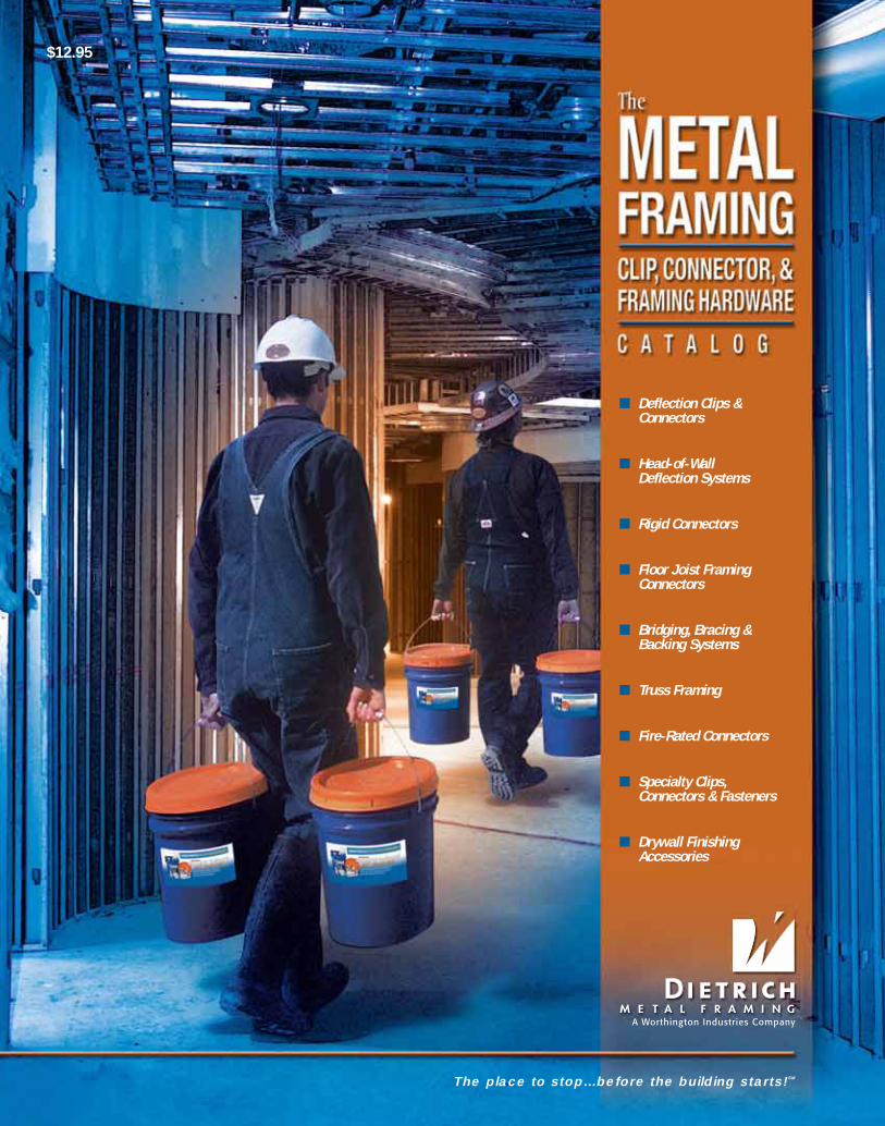
■ Deflection Clips & Connectors ■ Head-of-Wall Deflection Systems ■ Rigid Connectors ■ Floor Joist Framing Connectors ■ Bridging, Bracing & Backing Systems ■ Truss Framing ■ Fire-Rated Connectors ■ Specialty Clips, Connectors & Fasteners ■ Drywall Finishing Accessories The place to stop…before the building starts! SM $12.95 Dietrich Metal Framing The Metal Framing Clip, Connector, & Framing Hardware Catalog
Transcript of com Plant Locations · Worthington Industries is a leading diversified metal processing company...
■ Deflection Clips &Connectors
■ Head-of-Wall Deflection Systems
■ Rigid Connectors
■ Floor Joist FramingConnectors
■ Bridging, Bracing &Backing Systems
■ Truss Framing
■ Fire-Rated Connectors
■ Specialty Clips,Connectors & Fasteners
■ Drywall FinishingAccessories
The place to stop…before the building starts!SM
About Worthington IndustriesWorthington Industries is a leading diversified metal processing company with annual sales of approximately$3 billion. The Columbus, Ohio, based company is North America’s premier value-added steel processor anda leader in manufactured metal products such as metal framing, metal ceiling grid systems, pressure cylinders,automotive past model service stampings and laser welded blanks. The company employs more than 8,000people and operates 64 facilities in 10 countries.
©Copyright 2008 by Dietrich Industries, Inc. All rights reserved. DMF08/2008Printed in USA Form# 155 25M 09-08
Plant LocationsWorld Headquarters
200 Old Wilson Bridge Rd.
Columbus, OH 43085
800-873-2604
United StatesArizona Phoenix ............... 602-447-0204
California Colton ................ 909-824-9717Stockton .............. 209-547-9066
Colorado Denver ................ 303-289-4092Florida Miami .................. 305-652-5423
Georgia McDonough........ 678-304-5500Hawaii Kapolei ................ 808-682-5747Illinois Joliet ................... 815-207-0110
Indiana Hammond ........... 219-931-3741Kansas Lenexa ................ 913-599-2026
Maryland Baltimore............. 410-477-8700Massachusetts Lunenburg........... 978-342-9742
New Jersey Boonton............... 973-335-3240Ohio Warren ................ 330-372-4014
Texas Baytown .............. 281-383-1617Hutchins .............. 972-225-1100
Washington Renton ................ 425-251-1497International Miami .................. 305-652-5423
CanadaEdmonton ....................................... 780-469-9850Montreal ......................................... 514-368-7005Toronto ........................................... 905-565-9665Vancouver ...................................... 604-434-3737
Other Dietraich DivisionsAccelerated Building Technologies 412-490-5037Aegis Metal Framing ...................... 314-851-2200Vinyl Corp. ...................................... 800-648-4695Dietrich Design Group North .......... 800-873-2443
or ............................... 219-853-9474Dietrich Design Group South.......... 800-873-2443
or .............................. 678-304-5525Dietrich Design Group West ........... 800-873-2443
or .............................. 760-931-0465
dietrich metalframing •com
$12.95
Dietrich Metal Fram
ing The M
etal Framing Clip, Connector, & Fram
ing Hardware Catalog
A Worthington Industries Com
pany
081016 DMF_ClipExp08_ofc&obc:DMF_ClipExp07_ofc&obc 6/24/10 3:29 PM Page 1

dietrichmetalframing•comThe place to stop…before the building starts!SM
Take your own personal tour of North America’smost advanced resource for metal framing.
dietrich metalframing •comrequest a quote online @
CADLibraryTo assist you with
designing and
detailing. Our entire
library is available in
DWG, DXF and PDF
file formats.
ProjectSubmittalsDietrich’s on-line
submittal system is the
easiest way to create job submittals.
Point, click and print for fast, professional project submittals.
We make it easy for you to do business!
www.dietrichmetalframing.com is one of the most advanced
resources for metal framing information in the industry. From
extensive product information, to on-line catalogs, to video
installations, this site is your resource to building better, faster
and more profitably.
dietrich metalframing •com
INTRODUCTION
Dietrich Metal Framing is the largest producer of cold-formedmetal framing products in the world. As the industry leader,Dietrich provides the widest selection of products, systems,services and companies to provide the construction industrywith integrated, low-cost, single-source cold-formed framingsolutions. Dietrich believes leadership is about action — notsimply position. That’s why we continually strive to expandour existing markets, develop framing technologies, createvalue-added systems and introduce countless new productsto meet the ever-changing demands of the building andconstruction industry.
The Dietrich Clip ExpressSM delivery service is one of thenewest innovations from Dietrich Metal Framing. TheDietrich Clip ExpressSM delivery service is a dedicated productand delivery service specializing in meeting the connector, connection, support and framing hardware needs of the commercial and residential building industry. This highly specialized and focused support arm of Dietrich Metal Framingprovides you with the widest array of rigid, deflection, bridging and general-purpose clips, connectors, and light-gaugeframing hardware.
Clips, Connectors and Framing Hardware The Dietrich Clip ExpressSM service is your one stop shop for the widest and most cost-effective array of rigid, deflection, bridging and general-purpose clips, connectors,supports and framing hardware for light-gauge steel framing. Having the right products,at the right time and at the right price is critical to getting the job done. Turn to Dietrich ClipExpresssm as your source for:
■ Deflection Clips & Connectors■ Head-of-Wall Deflection Systems■ Rigid Connectors■ Floor Joist Framing Connectors■ Bridging, Bracing & Backing Systems■ Shear Wall and Header Connectors■ Truss Framing■ Fire-Rated Connectors■ Specialty Clips, Connectors
and Fasteners■ Drywall Finishing Accessories
Why Choose Dietrich?When you choose Dietrich Metal Framing clips,connectors and hardware you not only get thehighest-quality product available, you get thepeace-of-mind knowing your project is backedand supported by the largest light-gauge framingmanufacturer in the world. You get the peace-of-mind knowing that our products have beenextensively tested at our ICC certified testinglaboratory. That’s not all. You get:
■ Industry’s Widest Product Selection
■ Single Sourcing
■ Low Cost to Lowest Installed Costs Products
■ Next Day Delivery Available
■ Engineered Systems-Minimized Liability
■ Labor Saving Solutions
■ Product and Installation Training
■ FastClip™ Deflection Technology
■ Total Light-Gauge System Responsibility
■ Local Manufacturing with Global Distribution
■ Expert Technical Support
■ LEED® Certification
081016 DMF_ClipExp07_ifc&ibc:DMF_ClipExp07_IFC&IBC 6/24/10 3:18 PM Page 1
1
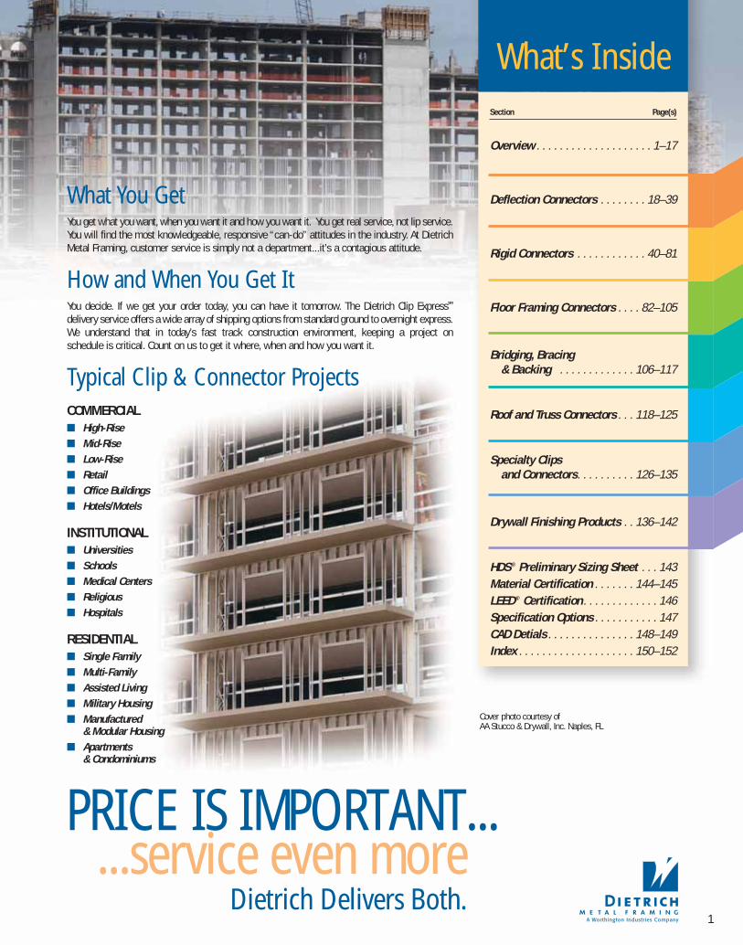
What’s InsideSection Page(s)
Overview . . . . . . . . . . . . . . . . . . . . 1–17
Deflection Connectors . . . . . . . . 18–39
Rigid Connectors . . . . . . . . . . . . 40–81
Floor Framing Connectors . . . . 82–105
Bridging, Bracing & Backing . . . . . . . . . . . . . 106–117
Roof and Truss Connectors . . . 118–125
Specialty Clips and Connectors. . . . . . . . . . 126–135
Drywall Finishing Products . . 136–142
HDS® Preliminary Sizing Sheet . . . 143Material Certification . . . . . . . 144–145LEED® Certification . . . . . . . . . . . . . 146Specification Options . . . . . . . . . . . 147CAD Detials . . . . . . . . . . . . . . . 148–149Index . . . . . . . . . . . . . . . . . . . . 150–152
Typical Clip & Connector ProjectsCOMMERCIAL■ High-Rise■ Mid-Rise■ Low-Rise■ Retail■ Office Buildings■ Hotels/Motels
INSTITUTIONAL■ Universities■ Schools■ Medical Centers■ Religious■ Hospitals
RESIDENTIAL■ Single Family■ Multi-Family■ Assisted Living■ Military Housing■ Manufactured
& Modular Housing■ Apartments
& Condominiums
What You Get You get what you want, when you want it and how you want it. You get real service, not lip service.You will find the most knowledgeable, responsive “can-do” attitudes in the industry. At DietrichMetal Framing, customer service is simply not a department...it’s a contagious attitude.
How and When You Get It You decide. If we get your order today, you can have it tomorrow. The Dietrich Clip ExpressSM
delivery service offers a wide array of shipping options from standard ground to overnight express.We understand that in today’s fast track construction environment, keeping a project on schedule is critical. Count on us to get it where, when and how you want it.
PRICE IS IMPORTANT...Dietrich Delivers Both.
...service even more
Cover photo courtesy of AA Stucco & Drywall, Inc. Naples, FL
081016 DMF Catalog 1-17.qxd:Pgs 1-17 6/24/10 3:33 PM Page 1

dietrich metalframing •com
PhoenixColton
Stockton
Renton
Vancouver
Edmonton
Kapolei, HI
about DIETRICHCLIP EXPRESS…
The Dietrich Clip ExpressSM Service is a dedicated and streamlined support and delivery system for steel framing connection products. It’s your source for fast and economicalconnection solutions. No matter what your needs, The DietrichClip ExpressSM Service can provide you with the products, pricingand quantities you need to keep your project moving. With hugefinished product inventories and a ship-it-now mentality, we’llkeep you on-time and under budget. With over 100 varieties ofclips and connectors to select from you can decide what worksbest for you. Choose from low cost products to our high performance line of lowest installed cost products or systems.
Look for the Blue and Orange Bucket. Your clip and connector orders areshipped in waterproof, easy to carry, easy to spot bright orange and bluebuckets. The buckets are easily resealable and when the clips are gonethey can be used for a variety of jobs around the construction site.
2
TM
081016 DMF Catalog 1-17.qxd:Pgs 1-17 6/24/10 3:33 PM Page 2
3
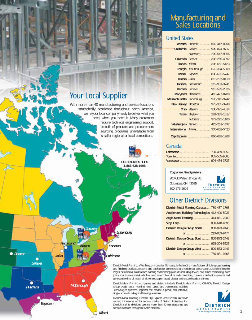
Your Local SupplierWith more than 40 manufacturing and service locations
strategically positioned throughout North America,we’re your local company ready to deliver what you
need, when you need it. Many customersrequire technical engineering support,breadth of products and procurementsourcing programs unavailable fromsmaller regional or local competitors.
Manufacturing and Sales Locations
United StatesArizona Phoenix ............... 602-447-0204
California Colton ................ 909-824-9717
Stockton .............. 209-547-9066
Colorado Denver ................ 303-289-4092
Florida Miami .................. 305-652-5423
Georgia McDonough........ 678-304-5500
Hawaii Kapolei ................ 808-682-5747
Illinois Joliet ................... 815-207-0110
Indiana Hammond ........... 219-931-3741
Kansas Lenexa ................ 913-599-2026
Maryland Baltimore............. 410-477-8700
Massachusetts Lunenburg........... 978-342-9742
New Jersey Boonton............... 973-335-3240
Ohio Warren ................ 330-372-4014
Texas Baytown .............. 281-383-1617
Hutchins .............. 972-225-1100
Washington Renton ................ 425-251-1497
International Miami .................. 305-652-5423
Clip Express ........................... 866-638-1908
CanadaEdmonton ....................................... 780-469-9850Toronto ........................................... 905-565-9665Vancouver ...................................... 604-434-3737
Other Dietrich DivisionsDietrich Metal Framing Canada ..... 780-437-1763
Accelerated Building Technologies 412-490-5037
Aegis Metal Framing ...................... 314-851-2200
Vinyl Corp. ...................................... 800-648-4695
Dietrich Design Group North .......... 800-873-2443
or ............................... 219-853-9474
Dietrich Design Group South.......... 800-873-2443
or .............................. 678-304-5525
Dietrich Design Group West ........... 800-873-2443
or .............................. 760-931-0465
Dietrich Metal Framing, a Worthington Industries Company, is the leading manufacturer of light-gauge framingand finishing products, systems and services for commercial and residential construction. Dietrich offers thelargest selection of cold-formed framing and finishing products including drywall and structural framing, floorjoists, roof trusses, metal lath, fire-rated assemblies, clips and connectors, numerous deflection systems andan extensive line of metal, vinyl, veneer, paper-faced, plaster and stucco beads and trims.
Dietrich Metal Framing companies and divisions include Dietrich Metal Framing CANADA, Dietrich DesignGroup, Aegis Metal Framing, Vinyl Corp., and Accelerated BuildingTechnologies Systems. Together, we provide superior, cost-effective,single-source building and framing solutions.
Dietrich Metal Framing, Dietrich Clip Express, and Dietrich, are tradenames, trademarks and/or service marks of Dietrich Industries, Inc.Dietrich and its divisions operate more than 40 manufacturing andservice locations throughout North America.
Miami
Baytown
Hutchins
Lenexa
Denver Joliet
Warren
CLIP EXPRESS HUBS1.866.638.1908
LunenburgToronto
ton
Boonton
Baltimore
McDonough
Corporate Headquarters
200 Old Wilson Bridge Rd.
Columbus, OH 43085
800-873-2604
Hammond
081016 DMF Catalog 1-17.qxd:Pgs 1-17 6/24/10 3:34 PM Page 3

dietrich metalframing •com
Connections play a vital role in the performance of light-gaugeframing assemblies. Connectors, clips or framing hardware areused to either make or support cold-formed framing connections. The most common types of connections are rigid( fixed) connections and deflection (movement) connections.Dietrich Metal Framing provides one of the widest selections ofconnectors, clips, supports and framing hardware for just aboutevery rigid or deflection connection. This wide selection ofoptions gives the designer the ability to attain optimalperformance at the most economical costs.
4
understanding FRAMINGCONNECTIONS
Rigid Connectors Rigid connectors and supports are used in a variety of ways to secure cold-formed framingmembers to each other or to the building structure. Some of the most common types ofrigid or fixed connections include joist connections, punched openings, beam/wall connections and bridging, header and truss connections.
Dietrich Metal Framing provides one of the widestselections of rigid connectorsand supports available. Thisextensive line provides a widearray of options to provide themost efficient load transferpath.
Design Considerations One of the most important considerations is load transfer. Whensizing a connector, it is important to consider forces in all directions. This could include shear, vertical or horizontal, tension, compression or moments. For the purpose of this catalog,the load capacities are defined by direction as listed below.
■ F1 = Shear■ F2 = Tension■ F3 = Compression■ M = Moment or Rotation
When we developed our extensive line of clips, connectors andframing hardware we did so with two key elements in mind:Provide cost effective solutions that satisfy design and performance requirements and reduce or streamline installation. By partnering with architects, specifiers,designers, engineers and installers, we were able to learn,understand and ultimately develop products and technologiesthat provide highly cost-effective solutions that satisfy buildingrequirements. Many of our products were developed by or inconjunction with framing installers who desperately sought efficient solutions to common framing problems. We delivered.
FastClip™ Technology Many of the Dietrich clips are embossed andprepunched to ensure accurate fastener placement and proper clip performance. TheFastClips™ and Uni-Clips™ also feature reinforced and stiffened corners that providesuperior design values for maximum performance and economy.
PRODUCTand performanceENHANCEMENTS
F3
F2
F1
M
081016 DMF Catalog 1-17.qxd:Pgs 1-17 6/24/10 3:34 PM Page 4

5
Easy-to-Read and Clearly Marked Connectors All too often, clips, connectors and supports arefabricated or made from local job shops or onthe jobsite from generic or surplus framing materials, which may or may not be the proper gauge,strength or coating needed to meet specific performance criteria.
In order to alleviate any liability or performance issues, Dietrich embosses almost every clip, connector or support with easy-to-find andeasy-to-read product identifiers so you can quickly verify that the properclip or connector is being used. When you design or specify by part nameor number, you know you’re getting an engineered connector and willeliminate any weak link between design and installation.
FastClip™
Deflection Screw
Deflection DistancesDeflection distance is a measure of the maximum vertical distance that the primary structure is anticipated to move due to the imposition and orremoval of “live loading.” Dietrich™ deflection productspermit deflection ranging from 1/2" to over 4" based on thespecific product. Each catalog page indicates the range ofdeflection so the designer can easily and economically choosethe correct connector to meet their specific requirements.
Standoff DistancesStandoff distance is defined as the distancebetween the secondary frame andthe primary frame. The primary frame is the mainbuilding structural supportusually consisting of red ironor concrete. The secondary frame isthe curtain-wall assembly comprised ofcold-formed light steel framing. Thestandoff distance allows for the framerto install the cold-formed framing in a“true” line while the structure of the building may vary either “in or out” or mayvary out of plumb from floor to floor. Dietrichdeflection clips permit or accept standoff fromas little as 1/8" up to 21" inches to accommodate just about every framing condition. Custom products are available to accommodate even greater standoff.
“FastClip™” Fasteners Many of the Dietrich deflection clips includeour proprietary “FastClip™” deflection screwthat has been specifically designed to providefriction-free deflection. These fasteners feature a smooth shoulder that eliminate drag,binding or resistance that can often occur withcommon fasteners. FastClip™ deflection screw:
■ Ensures friction-free deflection
■ Reduces the potential for overtightening
■ Eliminates the chance of using wrongfasteners
■ Correctly indicates proper fastenerplacement
■ No bushings or additional pieces thatfall out, get lost or never get used.
DeflectionConnectors Deflection or movement connectionsare designed to permit movement of the primary structure of the building without imposingany axial loading onto the exterior curtain wall orinterior head of wall. Movement of the primarystructure may result from thermal expansion and contraction, seismic disturbances, foundation settling or normal head ofwall compression. Deflection connectors are used in awide array of framing conditions including exterior,bypass, head of wall or infill and interior head of wall.Dietrich Metal Framing provides one of thewidest selections of deflection and slipconnections available. Thisextensive line provides awide array of options fromlowest installed costs tolowest unit costs so you candecide what works best for yourparticular situation. Many of the Dietrich™
deflection clips feature “FastClip™” technology. These “FastClips™” areembossed with fastening patterns toensure accurate and proper placement of fasteners. Specialty“FastClip™” Deflection Screws are also provided with each clip to ensure friction-free deflection.
081016 DMF Catalog 1-17.qxd:Pgs 1-17 6/24/10 3:34 PM Page 5
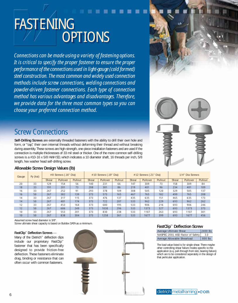
Screw Connections Self-Drilling Screws are externally threaded fasteners with the ability to drill their own hole andform, or “tap,” their own internal threads without deforming their thread and without breakingduring assembly. These screws are high-strength, one-piece installation fasteners and are used if theconnection is multiple thicknesses of 33 mil steel or thicker. One of the more common self-drillingscrews is a #10-16 x 5/8 HWH SD, which indicates a 10 diameter shaft, 16 threads per inch, 5/8length, hex washer head self-drilling screw.
FastClip™ Deflection Screws —Many of the Dietrich™ deflection clipsinclude our proprietary FastClip™
fastener that has been specificallydesigned to provide friction-freedeflection. These fasteners eliminatedrag, binding or resistance that canoften occur with common fasteners.
dietrich metalframing •com
FASTENING OPTIONS
Connections can be made using a variety of fastening options.It is critical to specify the proper fastener to ensure the properperformance of the connections used in light-gauge (cold formed)steel construction. The most common and widely used connectionmethods include screw connections, welding connections andpowder-driven fastener connections. Each type of connectionmethod has various advantages and disadvantages. Therefore,we provide data for the three most common types so you canchoose your preferred connection method.
6
#8 Screws (.16" Dia) #10 Screws (.19" Dia) #12 Screws (.21" Dia) 1/4" Dia ScrewsGauge Fy (ksi)
Shear Pullover Pullout Shear Pullover Pullout Shear Pullover Pullout Shear Pullover Pullout20 33 129 154 56 140 231 66 147 309 73 158 309 8418 33 191 201 73 208 301 86 219 401 96 234 401 10916 33 267 252 91 293 378 109 308 505 120 329 505 13716 50 267 382 139 373 573 165 467 765 182 499 765 20814 33 267 317 115 373 476 137 435 635 151 465 635 17314 50 267 481 174 373 722 207 533 962 229 693 962 26212 33 267 453 164 373 680 195 533 906 216 693 906 24612 50 267 686 249 373 1030 296 533 1373 327 693 1373 37310 33 267 553 201 373 830 238 533 1107 263 693 1107 30110 50 267 838 304 373 1258 361 533 1677 399 693 1677 456
Allowable Screw Design Values (lb)
Average Ultimate Shear 2400 lbsNASPEC 2001 ASD Factor of Safety 3.0Average Allowable Shearload 800 lbs
FastClip™ Deflection Screw
Assumed screw head diameter is 3/8".Screw ultimate shear capacity is based on Buildex DATA as a minimum.
The load value listed is for single shear. There maybeother controlling shear failure modes specific to theapplication (e.q. pull-through from slot, bearing failure)which are to be considered seperately in the design ofthat perticular application.
081016 DMF Catalog 1-17.qxd:Pgs 1-17 6/24/10 3:34 PM Page 6
7
WeldsGauge Fy (ksi)
FilletFlare
Groove20 33 *** ***18 33 482 40516 33 606 51016 50 721 51014 33 762 64114 50 907 64112 33 1087 91512 50 1294 91510 33 1328 111810 50 1581 1118
Allowable Weld Design Values(lbs) per inch of weld
PinGauge and Yield Strength (ksi) of Connected Part
Diameter20 18 16 14 12 1033 33 33 50 33 50 33 50 33 50
0.145" 179 233 292 443 368 558 526 796 642 9720.177" 218 285 357 541 450 681 642 972 783 1187
Allowable Hilti* Bearing Against Sheet Steel Design Values (lbs)
Fastener Shank 1/8" Steel 3/16" Steel 1/4" Steel 3/8" Steel 1/2" Steel 3/4" SteelType Diameter Shear Tension Shear Tension Shear Tension Shear Tension Shear Tension Shear Tension
X-EDNI .145" 230 110 425 455 620 800 680 810 605 850 545 500DS .177" — — 795 390 625 620 780 780 810 560 — —
Allowable Hilti* Powder-Driven Fastener Design Values in Structural Steel (lbs)
Shear values shall be checked against allowable bearing design values. The minimum value shall be used for design.Tension values shall be checked against pullout or pullover values and the minimum value used.Reference Hilti North America Products Technical Guide 2001 section 3.2.3.
Fastener Shank Min 2000 psi 3000 psi 4000 psi 6000 psiType Diameter Embed. Shear Tension Shear Tension Shear Tension Shear Tension
5/8" — — — — — — 60 45
X-DNI .145"3/4" 95 70 110 90 125 110 95 751" 140 90 160 120 185 155 195 130
1-1/2" 230 165 280 190 335 215 — —DS .177" 1-7/16" 250 150 285 205 330 275 — —
Allowable Hilti* Powder Driven Fastener Design Values in Normal Weight Concrete (lb)
Shear values shall be checked against allowable bearing design values and the minimum value used.Tension values shall be checked against pullout or pullover values and the minimum value used.Reference Hilti North America Products Technical Guide 2001 section 3.2.3.1
Powder-Actuated Connections Powder-actuated or low velocity driven-fasteners are commonly used to attach cold-formed steelframing members to concrete or structural steel supports. Drive pins are used for permanentattachments and are the most common type used for cold-formed construction.
Flare Bevel
Powder Driven Fasteners in Concrete
Minimum Fastener Spacing and Edge Distances:Light-Gauge SteelMinimum Slab Thickness: 3"4"
Powder-Driven Fasteners in Steel
Flare V
4"
Minimum Fastener Spacing and Edge Distances:Light-Gauge Steel
Welded Connections Fillet welds are used to make lap joints, cornerjoints and T-joint connections. As the illustrationsuggests, the fillet weld is roughly triangular incross-section, although its shape is not alwaysa right triangle or an isosceles triangle. Weldmetal is deposited in a corner formed by thefit-up of the two members and penetrates andfuses with the base metal to form the joint.
Flare welds, including Flare Bevel and Flare V,are used to join rounded or curved pieces.
A Flare Bevel groove weld is commonly usedto join a rounded or curved piece to a flat piece.
A Flare V groove weld is commonly used to jointwo rounded or curved parts.
NOTE: For graphical clarity, the weld illustrationsdo not show the penetration of the welded material.Weld penetration is critical in determining thequality of the weld.
Fillet welds
.5"1.5"
*Based on E60XX electrodes.
*Hilti is a registered trademark of the Hilti Aktiengeseilschaft Corporation.
081016 DMF Catalog 1-17.qxd:Pgs 1-17 6/24/10 3:34 PM Page 7

dietrich metalframing •com
how to USEthis MANUAL
This catalog is designed to help you select the right product orsystem for your construction applications. It is one of the mostcomprehensive light gauge steel connector, clip, support andframing hardware manuals in the industry. This catalog is dividedinto seven major sections that are color coded for easy reference.■ Deflection Clips and Connectors
■ Rigid Connectors
■ Floor Framing Clips, Stiffeners, Supports and Hangers
■ Bridging, Bracing and Backing Systems
■ Roof and Truss Connectors
■ Specialty Connectors and Fasteners
■ Drywall Finishing Accessories
8
Product LabelingThe majority of the connectors in this catalog followa very simple A, B, and C product code letteringsystem. It’s what we refer to as the A, B, C’s, oflight steel framing connectors. Each clip, connectoror support is clearly embossed with anidentifiable code so the installer can easily identifyand use the proper connection hardware. For theengineer or architect, the embossed markingsprovide a very easy way to field verify the correctconnector or hanger is used.
The majority of clips are packaged in distinct,easy to spot blue and orange buckets. Eachbucket is clearly labeled with the product code,gauge, size, length, dimensions, piece counts,and any special markings as requested. Basedon order quantity, buckets will be packed inskids for easy handling. Each skid is clearlyidentified with master skid labels that displayproduct, gauge, size, length, piece count and anyspecial skid markings as requested.
Product Page OverviewEach product page includes an extensive product overview, benefits, features andproduct and application renderings. In additionto application renderings each product pagefeatures common CAD details available atwww.dietrichmetalframing.com. Reference chartscontain size availability and packaging information.Each chart also includes metric sizing for yourconvenience.
All load tables are presented with multiple fasteningoptions including welding, powder driven fasteningand screw connections so you can determine themost efficient fastening method that’s right foryou. Each page also provides detailed fasteninginstructions including fastening patterns toachieve various levels of performance based oncondition requirements.Each section features a detailed building cutaway that showcases
the products for that particular section.
Comprehensive IndexA comprehensive index can be found at the back of the catalog for a quick reference guide to ourcomplete product and system offering, so you can easily locate the specific Dietrich product or sys-tem that meets your needs. This index includes common names, synonyms and even industryslang to help you quickly find exactly what you’re seeking.
Photo courtesy of AA Stucco & Drywall, Inc.
081016 DMF Catalog 1-17.qxd:Pgs 1-17 6/24/10 3:34 PM Page 8
9
Yield Strength, Fy/(psi or ksi)Yield strength is the property by which the strength of steel is typicallydefined. The majority of clips, connectors, supports and framing hardwareare manufactured from mill certified, ASTM A 1003 Structural Grade 50Type H (340 MPa) steel. KSI is short for kips per square inch. One kip isequal to 1,000 pounds.
Protective CoatingsDietrich Metal Framing offers a variety ofgalvanized products that can be selected tomeet the specific requirements of a project.
Non-structural products have a corrosion resistantgalvanized coating that conforms to ASTMspecification A1003 – G40 coating weight orequivalent corrosion protection. This coating is inaccordance with the industry standard coatingrequirements of ASTM C 645. These productscan also be ordered with enhanced coatings forspecial applications.
Structural Framing products are available with avariety of protective coatings. G60 zinc coatingsmeet the most widely applicable building codesand we are able to provide certified G60 productthat meets the G60 coating weight provisions ofASTM to C 955. Certified G90 coatings are anenhanced option that can be requested for highlycorrosive environments. G60E coatings are aneconomical choice. G60E coatings for structuralproducts will pass the 100-hour salt spray testapplicable to “equivalent” coatings under ASTMA 1003, but cannot be certified by any supplierto meet the G60 minimum coating standardunder ASTM C 955. The buyer is solely responsi-ble to assure that products purchased properlysatisfy any applicable code or specification.
Steel Thickness (Gauge)The steel thickness of a connector, clip, support or hanger is referenced in terms of gauge or mils. Thethickness or gauge is a key contributor to the strength of the product.
Note: All products comply with ASTM standards and Federal specifications as shown in Certification ofMaterials in the back of this catalog. Minimum thickness is 95% of the design thickness per AISI code.The trend today is to refer to steel thickness in terms of “mil” rather than “gauge”. This catalog includesboth for ease of use. One mil is equivalent to 1/1000, (0.001) of an inch. The mil thickness measuresthe uncoated base metal material. A 20-gauge stud measuring the minimum uncoated base metal at0.030 inches is “30 mils thick”.
Thickness
Gauge Mils Design Thickness Minimum ThicknessInches mm Inches mm
20 DW 30 0.0312 0.792 0.0296 0.75120 STR 33 0.0346 0.879 0.0329 0.835
18 43 0.0451 1.146 0.0428 1.08716 54 0.0566 1.438 0.0538 1.36714 68 0.0713 1.811 0.0677 1.72012 97 0.1017 2.583 0.0966 2.454
Steel Thickness
Section Title Product Illustrationswith Dimensions
Subsection TitleLoad Tables
Load Table Notes Color Tab
ApplicationIllustrations
Sizing andPackagingInformation
ProductName and Code
FeaturesandBenefits
InstallationInstructions CAD
Drawings
*ASTM is a registered trademark of the American Society for Testing and Materials.
081016 DMF Catalog 1-17.qxd:Pgs 1-17 6/24/10 3:34 PM Page 9

dietrich metalframing •com10
how to USEthis MANUAL
continued
Standards & SpecificationsAll structural properties are developed in accordancewith the American Iron and Steel Institute’s (AISI’s)“Specification for the Design of Cold-Formed SteelStructural Members.”
Metric SpecificationsAt your request, Dietrich Metal Framing will provide“soft” metric conversions on its products and systems to help specifiers match metric designsizes. In addition, some products are availablewith hard metric dimensions from selected manufacturing facilities.
WarrantyOur products are manufactured in accor-dance with company standards and/orindustry standards, as applicable. AllDietrich Metal Framing products are covered by our standard warranty which is contained in our Standard Terms and Conditions of Sale and which will beprovided upon request. Generally, we warrant our products will be free fromdefects in material and workmanship at thetime of shipment, subject to the limitationsstated in the warranty. Unless specificallyagreed in writing by us with respect to specific orders, we do not make any warranty of merchantability or fitness for aparticular purpose. The buyer is responsibleto assure that buyer orders the appropriateproduct for any applicable code or specifi-cation requirements.
NOTICE: Our liability is expressly limited toreplacement of defective products. We shallnot be liable for incidental and consequentialdamages, nor for any loss caused by misuseor misapplication of our products. Any claimshall be deemed waived unless made in writing to us within thirty (30) days fromthe date it was or reasonably should havebeen discovered.
WARNING: Not All LoadTables are Created Equal
It is critical that the allowable load tables for clips, connectorsand fasteners are interpreted correctly. Especially when comparing the performance criteria from one company’s clip toanother. The allowable load for a clip assembly is governed notonly by the capacity of the clip, but also by the method of attachment to the structure. Some manufacturers provide tablesthat display allowable loads for the clip, while ignoring theattachment to the structure. Unfortunately, when attaching aclip to the structure with pins, screws, welds or concrete anchorsthe overall capacity can often be lower than the publishedvalue. Load tables that ignore the attachment to the structureessentially imply that the clip or connector must be welded toachieve the stated values. More often than not, clips and connectors will not be welded based on the installation costs.
In order to provide more accurate and realistic data, DietrichMetal Framing publishes its values for multiple attachmentmethods. That way the designer or engineer will have the proper information to correctly determine the appropriate clipor connector and have confidence that all load requirementshave been satisfied. As an example, the tabulated valuesDietrich provides for the FastClip™ includes data for 0.145 Hilti* X-EDNI pins and Buildex** #12-24 screws.
*Hilti is a registered trademark of the Hilti Aktiengeseilschaft Corporation.
**Buildex is a registered trademark of Illinois Tool Works, Inc.
Be aware and make sure you aren’t comparing apples to oranges.
081016 DMF Catalog 1-17.qxd:Pgs 1-17 6/24/10 3:34 PM Page 10
11
General NotesThe data contained in this brochure is intendedto be used as a general guideline only and doesnot replace the judgments and designs of aqualified architect and/or engineer. Product,application renderings and photographs areprovided as a tool to show the general intent ofthe framing or finishing application only. Theserenderings or photographs may or may not beapplicable to a specific project. They do notreplace or supercede the architect or engineer ofrecord, ASTM guidelines, national or localbuilding codes or approved industry standards.It is the responsibility of the design engineer toproperly detail project drawings and documentsfor proper clip installation.
■ Install products per installationinstructions detailed in this catalog.
■ Install all connectors and fastenersbefore load application.
■ Do not modify, change or alter any connector in this catalog.
■ Do not bend connectors unless they are specifically designed to be bent.Connectors that are not designed to be bent may fracture. Fractured steel will not carry load and must bereplaced. Connectors that are designedto be bent shall only be bent one time.
■ Install fasteners per the manufacturer’sinstructions.
■ Load tables have been developed using the following fastener data:
■ Hilti 0.145” dia. X-EDNI fasteners –Reference 2002 Edition of the Hilti North American Product Technical Guide, page 29 for 3/16” steel
■ Hilti Kwik-Con II – Reference 2002Edition of the Hilti North AmericanProduct Technical Guide, page 180
■ #10-16 Screws – As applicable,capacities calculated according to the AISI North American Specificationfor the Design of Cold-Formed SteelMembers. The ultimate nominal screw shear capacity must be 1400# or greater.
■ Tabular footnotes must be followed and supercede general notes when in conflict.
■ Fasteners other that those specified may be substituted with the approval of the engineer of record
■ Allowable loads and material data listed in this catalog supercedes allinformation in previous publications
■ Allowable loads, in some cases, havebeen increased 1/3rd per allowablecodes. It is important to verify that the actual installation meets therequirements to allow the 1/3rdincrease. If not the engineer of recordshould adjust the loads down.
■ Listed loads are the maximummonotonic design loads to be applied to the connection based on testing or calculations. Load tables have been developed using Allowable Stress Design methodologies.
■ Allowable loads are the maximum forcesapplied in one direction only. When loadsare applied in multiple directions theengineer of record is responsible toverify the maximum capabilities basedon an appropriate interaction equation
■ Where maximum movements (deflections) are specified they are the total movement in both directions. The fastener positioning and size will affect the amount of allowable movement.
Dietrich Metal Framing strongly recommendsthe following language be included in plansand specifications: “Dietrich Metal Framing con-nectors were utilized in developing the plansand specifications for this project. Before substi-tuting another brand, the engineer of recordmust verify the load capacities and approve thesubstitution in writing.”
Dietrich Metal Framing reserves the rightto change or modify the information and tech-nical data contained in this catalog withoutprior notice or obligation. The informationin this catalog supercedes all previously pub-lished data. Products and systems may beimproved and/or changed after this catalog isprinted.
All products described here may not be avail-able in all geographic markets. Consult yourlocal sales office for information.
PatentsU.S. Patent Nos. 5,784,850; 6,021,618; 6,694,695;
5,689,922; 6,301,854; 6,691,478;6,418,694; 6,430,890, 6,688,069 and 6,708,460 are owned by Dietrich Industries, Inc.
U.S. Patent Nos. 5,467,570; 6,230,467 are owned by Simpson Strong-Tie® Company, Inc.
U.S. Patent No. RE39,462 is owned by SlipTrack Systems, Inc.
U.S. Patent No. 5,836,133 is owned by B&D Industries, Inc.
U.S. Patent No. 6,705,056 is owned by Daniel W. Tollenaar.
TrademarksDietrich Metal Framing and Dietrich are trade names, trademarksand service marks of Dietrich Industries, Inc.
TRADEREADY®, SPAZZER®, FAST CLIP™, EASYCLIP™, FAST TOP™,FAST STRUT™, UNI-CLIP™, DOUBLETRACK™, THIS BUCKET COULDSAVE YOUR BUTT!™, ONE CALL CAN DO IT ALLSM, THE PLACETO STOP BEFORE THE BUILDING STARTSSM, SPAZZER andDesign™, BEST VALUE and Design™, YOUR BEST VALUE™,DIETRICH CLIP EXPRESSSM, DIETRICH CLIP EXPRESS andDesignSM, BAR GUARD™, B-SERIES™, BP-SERIES™, C-SERIES™,CA-SERIES™, CS-SERIES™, CHN-SERIES™, DT-SERIES™,DTN-SERIES™, E-SERIES™, FC-SERIES™, M400-SERIES™,OT-SERIES™, QC-SERIES™, S-SERIES™, TD-SERIES™, TR-SERIES™,TS-SERIES™, U-SERIES™, X-SERIES™, ZF-SERIES™, EVERYTHINGYOU NEED, WHEN YOU NEED IT, HOW YOU NEED IT AND WHERE...YOU NEED ITSM, HDS® Header System are owned by DietrichIndustries, Inc.
ULTRA-SPAN® is a registered trademark of Aegis Metal Framing LLC
QUICKCLIP® is a registered trademark of B & D Industries.
DANBACK® is a trademark of Daniel W. Tollenaar
GRABBER® and are registered trademarks of GRABBER SUPERDRIVE® John Wagner Associates, Inc.
LOX DRIVE® is a registered trademark of JJCT Enterprises, Inc.
SIMPSON® and are trademarks of SIMPSON STRONG-TIE® Simpson Strong-Tie Company, Inc.
SLP-TRK® is a registered trademark of Sliptrack Systems, Inc.
UL® and UL and Design® are trademarks of Underwriter's Laboratories, Inc.
TAPCON® is a registered trademark of Illinois Tool Works, Inc.
© 2007 Dietrich Industries, Inc. All rights reserved. Printed in U.S.A.
WARNING: Handling of this productwithout the proper use of hand and eyeprotection may result in injury.
081016 DMF Catalog 1-17.qxd:Pgs 1-17 6/24/10 3:34 PM Page 11

dietrich metalframing •com
the “CLIP EXPRESSSM”difference
More products…more options…and more value with fast,accurate and reliable service at economical prices. It’s whatyou expect from a leader—it’s what you get from Dietrich ClipExpress.SM
12
Single SourcingOne company provides the entire light-gaugeframing package from design to delivery.
Industry’s WidestProduct SelectionThe industry’s widest selection of framingconnectors and clips for deflection, rigid, floor,roof, truss, header, shear wall and specialtyconnections.
Engineered ProductsWhen you design or specify by Dietrich productname or number you get fully engineered andrigorously tested connectors. Eliminate anychance that inferior or untested job shop or jobsite modified connectors or clips are beingused.
Lowest Installed CostMany of our products are specifically designedto achieve or provide lowest cost installationalternatives. Based on the design requirements and installation proceduresthese products provide significant installedsavings.
Superior Quality“Zero” defects is our goal. You get the samehigh quality, consistent, precision-formedproducts each and every time. Your and ourreputation depend on it.
EVERYTHING you need, when you need it,
081016 DMF Catalog 1-17.qxd:Pgs 1-17 6/24/10 3:34 PM Page 12
13
System Responsibility and Limited LiabilityWhen you specify, design or build with the entire line of Dietrich framingand connection products, you are using engineered systems by one company and one material source. Eliminate multiple liability concerns byusing tested, approved and reliable engineered systems.
Fast DeliveryWe ship most orders the same day they are received. You choose theshipping option from standard ground service to overnight express. We’llget it there when, how and where you want it.
National Distribution40+ manufacturing and service locations in North America with facilitiesin or near most major metropolitan cities servicing all 50 states andCanada. Dietrich is the acknowledged leader when it comes to supportingthe supply requirements of large national and multi-national customers.
Labor Saving SolutionsMany of our connectors were developed by or in conjunction with framinginstallers in order to develop and deliver the lowest installed cost, highestperformance products.
Expert Technical SupportThe finest light gauge technical assistance and support in the world. From shopdrawings, to design assistance, we respond to over 30,000 calls per year.
Extensively Tested Products & AssembliesOur products have been rigorously and extensively tested under the AmericanIron and Steel Institutes specifications to ensure product performance.
Peace-of-MindThat’s what you’ll get when you design, engineer or build with the entireline of Dietrich Metal Framing products, connectors, clips, supports andhangers. You’ll have peace-of-mind knowing the entire framing system isbacked by the largest light gauge framing and light gauge engineeringcompany in the world.
New Product DevelopmentWe continually develop and introduce countless new products, systemsand services to meet the expanding needs of the construction industry.We continually focus on developing products that keep costs down andproductivity up.
Product & TrainingOur field representatives are recognized as experts in the industry. Theyprovide comprehensive product, installation and sales training.
LEED® CertificationDietrich Metal Framing can significantly contribute towards achievingLEED credits in several areas including 4.1 and 4.2.
*LEED® is a registered trademark of the Green Building Council.
You Get… What You Pay for
You can always find someone with a cheaperprice. But no one will offer a lower overall costand better value. We go far beyond supplyingproducts. No matter where you are in the supply chain, Dietrich will streamline thedesign, procurement and building processwhile improving reliability, quality, productivityand your bottom line.
how you need it and where…
YOU NEED IT.SM
081016 DMF Catalog 1-17.qxd:Pgs 1-17 6/24/10 3:34 PM Page 13

AEC support
and SERVICESDietrich offers unparalleled support, training, education andproject assistance to design, engineering and building profes-sionals. We have the products, systems, services and compa-nies that can help you drive cost out of the building process.
Architects and Specifiers■ CEU On-Site and On-Line Learning
■ Technical Assistance
■ LEED* Accredited Professionals
■ On-Line Specifications, Certifications and Code-Body Approval Reports
■ Integrated Light-Gauge Framing Systems
■ National and World-Wide Availability
■ Design/Build Support and Assistance
■ Extensive Light-Gauge CAD Library
■ Prefabricated and Turnkey Light-Gauge Building Systems
Engineering and Design Professionals■ Broadest Product Selection for Cost Effective Design and Building
■ Boxed-Lunch Learning Sessions
■ Certified/Sealed Shop Drawing in all 50 States
■ Extensive Light-Gauge CAD Library
■ Design Build Assistance
■ Advanced Light-Gauge FramingTechnologies
Contractors and Builders■ On-Site Product Demonstrations
■ Certified/Sealed Shop Drawing in all 50 States and Canada
■ Technical Support
■ On-Line Submittal Builder
■ Products and Services that Reduce Costs and Improve Productivity
* LEED® is a trademark of the Green Building Council.14
HOPSON SPECIALTY SYSTEMS
DRYWALL CONSTRUCTION
ACOUSTICAL CEILINGS • LATHING AND PLASTERING • SPRAYED FIREPROOFING • DEMOUNTABLE PARTITIONS
SOUND CONTROL • EXTERIOR INSULATION FINISH SYSTEMS • INSULATION
RELATED MATERIALS
February
5, 2004
Re: A de
served t
estimoni
al
Dietrich
Design
Group
1414 Fie
ld Stree
t
Building
C
Suite 1
Hammond,
Indiana
46320
Attentio
n: Mr Mi
chael C.
Kerner,
Manager
of Tech
nical Se
rvices
Dear Mik
e,
Our rela
tionship
with Di
etrich s
pans man
y years.
This is
our twe
nty-fift
h year a
nd throu
ghout
our hist
ory, we
can say
with all
candor
that Die
trich De
sign Gro
up has b
een a si
lent par
tner in
aiding u
s to att
ain a st
rong pre
sence in
the col
d-formed
metal f
raming s
ector of
the mar
ket
which we
serve.
We have
said in
the past
and con
tinue to
believe
that
our destin
y, indee
d
Dietrich
Industr
ies, Inc
.?s dest
iny too, r
ests squ
arely on
the sho
ulders o
f Dietri
ch Desig
n Group,
since me
tal fram
ing cont
inues to
be the
product
of choic
e in the
commerc
ial cons
truction
market a
nd conti
nues to
develop
a presen
ce in th
e light
commerci
al as we
ll as th
e reside
ntial
sector.
ignGrou
p elevat
es metal
framing
from be
ing just
another
commodi
ty item
essen
-
through
its well
-staffed
, well-e
ducated,
dedicat
ed and c
ommitted
enginee
r
-
is the ften
than not
, one sp
eaks wit
h a REAL
person�
and for
is necessar
y, human
follow-
up ALWAY
S occurs
.
dramatic
ally; it
is rare
that a
week
ious mem
bers of
your
with DDG
.
081016 DMF Catalog 1-17.qxd:Pgs 1-17 6/24/10 3:34 PM Page 14
15
TECHNICAL assistance& SUPPORTSpecialized Services for
Specialized Needs
FREE Preliminary DesignDietrich Design Group provides unparalleled customer support through our free preliminary designservice. Customers can e-mail or fax building cross-sections, or can express mail full-size projectplans and specifications. This valuable design service provides the critical information that can helpcustomers during the bidding process.
FREE Technical Support HotlineWe respond to more than 30,000 calls each year through our Technical Support Hotline. This uniqueand value-added service provides immediate response to engineers, architects, contractors andbuilders, ranging from general questions to detailed specification interpretations.
Certified Shop DrawingsThrough our in-house engineering staff,Dietrich Design Group provides certified shopdrawings and calculations. This service providesour customers with the most detailed, easy-to-use drawings, and the most cost-effectiveframing solutions in the industry. From multi-story load-bearing structures to curtainwallconstruction, no matter how big or small thejob, DDG is there to help. Our lead-times andfees are among the best available.
The “Dietrich”AdvantageDietrich Metal Framing is the industry leader insteel-framing products for the residential andcommercial markets. Dietrich Design Groupsupports these products through engineeringand technical expertise and superior customerservice. Together, customers have a one-stopresource for completing projects on time andwithin budget—all backed by safe, reliableand trusted products and technical expertise.
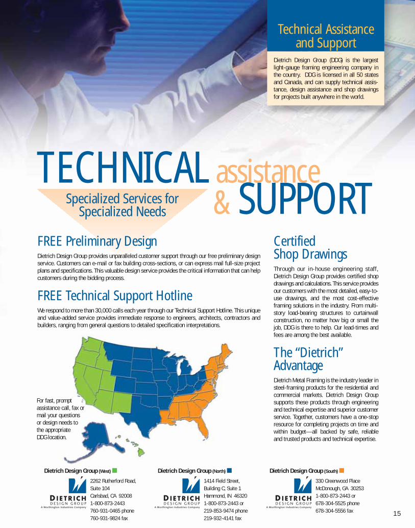
Technical Assistanceand Support
Dietrich Design Group (DDG) is the largestlight-gauge framing engineering company inthe country. DDG is licensed in all 50 statesand Canada, and can supply technical assis-tance, design assistance and shop drawingsfor projects built anywhere in the world.
For fast, prompt assistance call, fax or mail your questions or design needs to the appropriate DDG location.
Dietrich Design Group (North) ■
1414 Field Street, Building C, Suite 1Hammond, IN 463201-800-873-2443 or 219-853-9474 phone219-932-4141 fax
Dietrich Design Group (West) ■
2262 Rutherford Road,Suite 104Carlsbad, CA 920081-800-873-2443760-931-0465 phone760-931-9824 fax
Dietrich Design Group (South) ■
330 Greenwood PlaceMcDonough, GA 302531-800-873-2443 or 678-304-5525 phone678-304-5556 fax
081016 DMF Catalog 1-17.qxd:Pgs 1-17 6/24/10 3:34 PM Page 15

dietrich metalframing •com
one CALLcan do it ALL
ShippingNeed it fast — we ship 95% of in-stock orderswithin 48 hours.
OrderingPhone, fax, e-mail or EDI — you decide.
ServiceFar more than order takers, Dietrich CustomerCare Representatives are experts in the industry.Let us put our knowledge to work for you.
SupportHave questions? We have the answers. Call, faxor e-mail us and we will answer your questionspromptly.
ProductsWe have over 3,000 different products/productcombinations. The largest selection of products inthe industry. One call that truly does it all.
CustomWhen “off-the-shelf” just won’t do, call Dietrich.We can custom fabricate and provide made-to-order products to meet your needs.
16
E-BusinessWe make it easy for you to do business. Fast,flexible options to make you more efficient,reduce procurement and administrative costsand improve productivity.
■ EDI — Electronic Data Interchange
■ Flexible invoicing by mail, fax, e-mail or EDI
■ Easy payment options by check, wiretransfer or credit card
Dietrich is committed to ongoing developmentof technologies and e-business solutions tolower procurement costs.
SM
081016 DMF Catalog 1-17.qxd:Pgs 1-17 6/24/10 3:34 PM Page 16

17
CUSTOMER careConvenient OrderingWith just one call, you can reach the expert sales and support team for prices, availability, ordering, technical support or additional information on our over 3,000 products.
At Dietrich, our Customer Care Representatives are ready to help you with all your needs. Ourskilled, knowledgeable staff utilizes a sophisticated order entry system to ensure customer ordersand inquiries are handled quickly and accurately.
We Get It Right the First TimeThe clip order you placed on Monday with another company arrives on Thursday and you find outit’s wrong. What a mess. Now you have to deal with that very upset contractor waiting for the material, not to mention all the paperwork, phone calls and hassles that go along with a wrongorder. Maybe next time you’ll turn to Dietrich. We get it right the first time.
Starting with the order process, our Customer Care Representatives double and triple check eachand every order. Next, we send you a faxed confirmation to verify the correct size, gauge, length,piece count and price.
Using state-of-the-art manufacturing technologies and automated production control, your order ismanufactured to exact specifications. Every step of the way numerous quality control checks aremade to ensure the highest product quality and integrity. When your order is completed and readyfor transit, each unit is automatically reconciled against the pick list using detailed bar code tracking. The truck cannot be released until the order completely reconciles. It’s no wonder Dietrichhas one of the best fill-rates in the business.
“Can Do” AttitudeIf there is a way, we go the extra mile to find it and do it. We know the success of your business depends on our ability to get it when you want it, how you want it and where you want it.No one works harder to exceed your expectations.
Your Business Is Built on ServiceThat’s why our Customer Care Representatives are dedicated to immediate and quick response. If we can’t answer your inquiry immediately, we will within 60 minutes. It’s our commitment to you.
CustomerCare
It’s all about taking care of you. We get it. Weunderstand that you are the lifeblood of ourbusiness. Our world revolves around you.That’s why we do everything in our power to make sure you experience world-class customer care each and every time.
081016 DMF Catalog 1-17.qxd:Pgs 1-17 6/24/10 3:34 PM Page 17
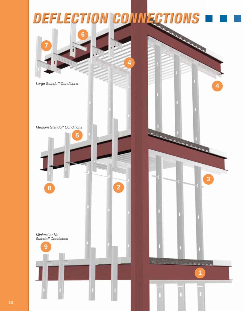
1
23
4
4
5
8
9
18
Large Standoff Conditions
Medium Standoff Conditions
Minimal or NoStandoff Conditions
7
6
081016 DMF Catalog 18-39.qxd:Pgs 18-39 6/24/10 3:31 PM Page 18
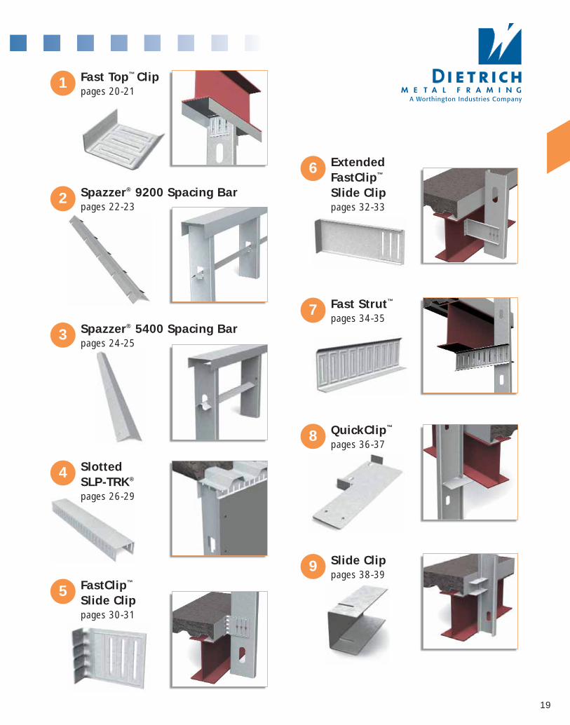
19
1 Fast Top™ Clippages 20-21
5 FastClip™
Slide Clippages 30-31
7 Fast Strut™
pages 34-35
2 Spazzer® 9200 Spacing Barpages 22-23
3 Spazzer® 5400 Spacing Barpages 24-25
4 Slotted SLP-TRK®
pages 26-29
6 Extended FastClip™
Slide Clippages 32-33
8 QuickClip™
pages 36-37
9 Slide Clippages 38-39
081016 DMF Catalog 18-39.qxd:Pgs 18-39 6/24/10 3:31 PM Page 19
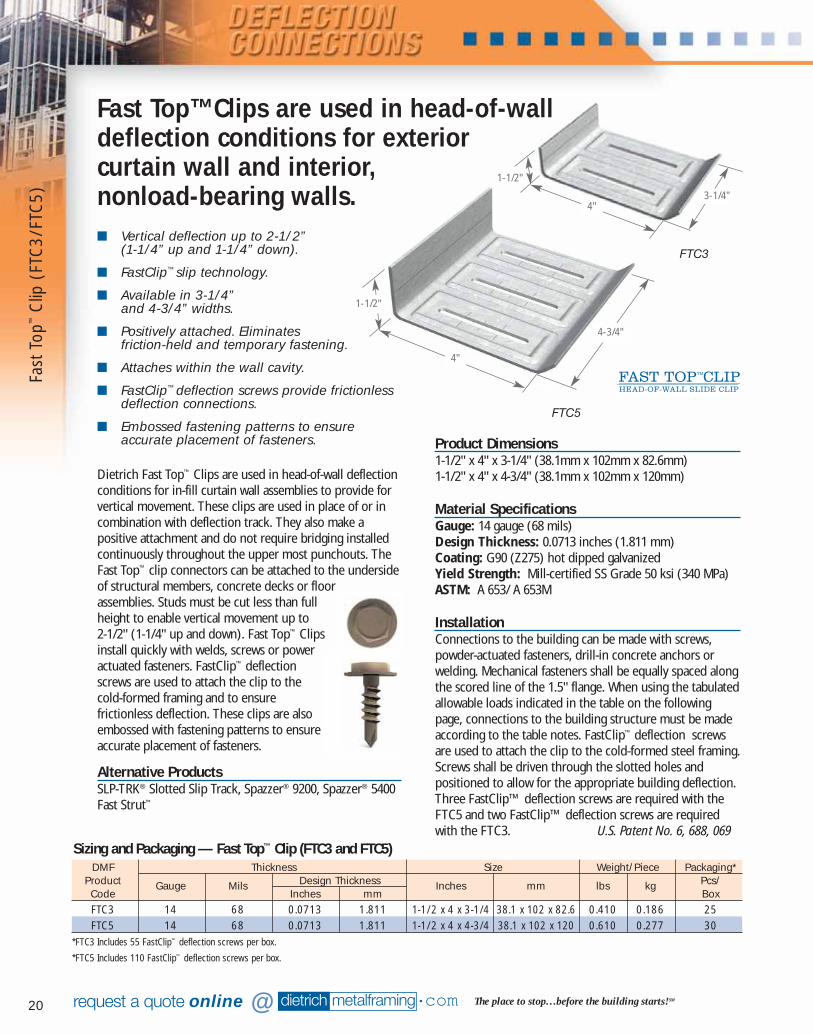
20
■ Vertical deflection up to 2-1/2” (1-1/4” up and 1-1/4” down).
■ FastClip™ slip technology.
■ Available in 3-1/4” and 4-3/4” widths.
■ Positively attached. Eliminates friction-held and temporary fastening.
■ Attaches within the wall cavity.
■ FastClip™ deflection screws provide frictionlessdeflection connections.
■ Embossed fastening patterns to ensureaccurate placement of fasteners.
dietrich metalframing •com The place to stop…before the building starts! SMrequest a quote online @
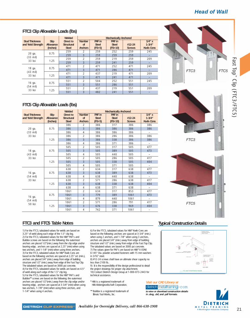
Dietrich Fast Top™ Clips are used in head-of-wall deflectionconditions for in-fill curtain wall assemblies to provide forvertical movement. These clips are used in place of or incombination with deflection track. They also make apositive attachment and do not require bridging installedcontinuously throughout the upper most punchouts. TheFast Top™ clip connectors can be attached to the undersideof structural members, concrete decks or floorassemblies. Studs must be cut less than fullheight to enable vertical movement up to 2-1/2" (1-1/4" up and down). Fast Top™ Clipsinstall quickly with welds, screws or poweractuated fasteners. FastClip™ deflectionscrews are used to attach the clip to thecold-formed framing and to ensurefrictionless deflection. These clips are alsoembossed with fastening patterns to ensureaccurate placement of fasteners.
Alternative ProductsSLP-TRK® Slotted Slip Track, Spazzer® 9200, Spazzer® 5400Fast Strut™
DMF Thickness Size Weight/Piece Packaging*Product Gauge Mils Design Thickness Inches mm lbs kg Pcs/Code Inches mm BoxFTC3 14 68 0.0713 1.811 1-1/2 x 4 x 3-1/4 38.1 x 102 x 82.6 0.410 0.186 25FTC5 14 68 0.0713 1.811 1-1/2 x 4 x 4-3/4 38.1 x 102 x 120 0.610 0.277 30
*FTC3 Includes 55 FastClip™ deflection screws per box.
*FTC5 Includes 110 FastClip™ deflection screws per box.
Sizing and Packaging — Fast Top™ Clip (FTC3 and FTC5)
Product Dimensions1-1/2" x 4" x 3-1/4" (38.1mm x 102mm x 82.6mm)1-1/2" x 4" x 4-3/4" (38.1mm x 102mm x 120mm)
Material SpecificationsGauge: 14 gauge (68 mils)Design Thickness: 0.0713 inches (1.811 mm)Coating: G90 (Z275) hot dipped galvanized Yield Strength: Mill-certified SS Grade 50 ksi (340 MPa)ASTM: A 653/ A 653M
InstallationConnections to the building can be made with screws,powder-actuated fasteners, drill-in concrete anchors orwelding. Mechanical fasteners shall be equally spaced alongthe scored line of the 1.5" flange. When using the tabulatedallowable loads indicated in the table on the followingpage, connections to the building structure must be madeaccording to the table notes. FastClip™ deflection screwsare used to attach the clip to the cold-formed steel framing.Screws shall be driven through the slotted holes andpositioned to allow for the appropriate building deflection.Three FastClip™ deflection screws are required with theFTC5 and two FastClip™ deflection screws are requiredwith the FTC3. U.S. Patent No. 6, 688, 069
4"3-1/4"
4"
1-1/2"
1-1/2"
Fast Top™ Clips are used in head-of-walldeflection conditions for exterior curtain wall and interior, nonload-bearing walls.
4-3/4"
FTC5
FTC3
Fast
Top
™C
lip (
FTC
3/FT
C5)
081016 DMF Catalog 18-39.qxd:Pgs 18-39 6/24/10 3:32 PM Page 20
21
FTC3 and FTC5 Table Notes
FTC3 Clip Allowable Loads (lbs)Welded Mechanically Anchored
Stud Thickness Slip Direct to Number PAF in PAF in 1/4" xand Yield Strength Allowance Structural of Steel Steel #12-24 1-3/4"
(Inches) Steel Anchors (FS=5) (FS=10) Screws Kwik-Cons
20 ga. 0.75259 2 259 252 259 245
(33 mil)259 3 259 259 259 –
33 ksi 1.25259 2 259 219 259 209259 3 259 241 259 –
18 ga. 0.75471 2 471 252 471 245
(43 mil)471 3 471 286 471 –
33 ksi 1.25471 2 437 219 471 209471 3 471 241 471 –
16 ga. 0.75551 2 504 252 551 245
(54 mil)551 3 551 286 551 –
33 ksi 1.25551 2 437 219 551 209551 3 482 241 551 –
FTC5 Clip Allowable Loads (lbs)Welded Mechanically Anchored
Stud Thickness Slip Direct to Number PAF in PAF in 1/4" xand Yield Strength Allowance Structural of Steel Steel #12-24 1-3/4"
(Inches) Steel Anchors (FS=5) (FS=10) Screws Kwik-Cons386 2 386 317 386 386
20 ga. 0.75 386 3 386 386 386 386(33 mil) 386 4 386 386 386 –33 ksi 386 2 386 286 386 386
1.25 386 3 386 338 386 386386 4 386 371 386 –505 2 505 317 505 477
18 ga. 0.75 505 3 505 389 505 473(43 mil) 505 4 505 440 505 –33 ksi 505 2 505 286 505 417
1.25 505 3 505 338 505 404505 4 505 371 505 –638 2 634 317 638 477
16 ga. 0.75 638 3 638 389 638 473(54 mil) 638 4 638 440 638 –33 ksi 638 2 571 286 638 417
1.25 638 3 638 338 638 404638 4 638 371 638 –1061 2 634 317 853 477
16 ga.0.75 1061 3 779 389 1061 473
(54 mil)1061 4 879 440 1061 –
50 ksi1061 2 571 286 791 417
1.25 1061 3 676 338 969 4041061 4 742 371 1061 –
Available for Overnight Delivery, call 866-638-1908
1) For the FTC3, tabulated values for welds are based on3.25" of weld along each edge of the 1.5" clip leg.2) For the FTC3, tabulated values for the Hilti* PAF's andBuildex screws are based on the following: the outermostanchors are placed 1/2"(min.) away from the clip edge and/orbearing edge, anchors are spaced at 2.25" (min) when usingtwo anchors, and 1-1/8" (min) when using three anchors.3) For the FTC3, tabulated values for Hilti* Kwik-Cons arebased on the following: anchors are spaced at 2.25" o/c (min.),anchors are placed 3/4" (min.) away from edge of buildingstructure and 1/2" (min.) away from edge of the Fast Top Clip.The tabulated values are based on 3000 psi concrete.4) For the FTC5, tabulated values for welds are based on 4.5"of weld along each edge of the 1.5" clip leg. 5) For the FTC5, tabulated values for the Hilti* PAF's andBuildex** screws are based on the following: the outermostanchors are placed 1/2"(min.) away from the clip edge and/orbearing edge, anchors are spaced at 3-3/4" (min) when usingtwo anchors, 1-7/8" (min) when using three anchors, and 1-1/4" when using 4 anchors.
6) For the FTC5, tabulated values for Hilti* Kwik-Cons arebased on the following: anchors are spaced at 3-3/4" (min.)when using 2 anchors, and 1-7/8" when using 3 anchors,anchors are placed 3/4" (min.) away from edge of buildingstructure and 1/2" (min.) away from edge of the Fast Top Clip.The tabulated values are based on 3000 psi concrete. 7) The values given for PAF's are based on Hilti* X-EDNI0.145" Dia. powder actuated fasteners with 15 mm washersin 3/16" steel.8) #12-24 screws shall have an ultimate shear capacity noless than 2100 lb..9) It is the responsibility of the design professional to detailthe project drawings for proper clip attachment.10) Contact Dietrich Design Group at 1-800-873-2443 fortechnical assistance.
* Hilti is a registered trademark of Hilti Aktiengeseilschaft Corporation.
** Buildex is a registered trademark of Illinois Tool Works, Inc.
Typical Construction Details
dietrich metalframing •comto view or download construction details in .dwg, .dxf, and .pdf formats.
Visit our CAD Library at
Head of Wall
FTC3
FTC3
FTC5
FTC5
Fast Top™
Clip (FTC
3/FTC5)
081016 DMF Catalog 18-39.qxd:Pgs 18-39 6/24/10 3:32 PM Page 21

22
■ Eliminates high material cost of custom-madehead tracks.
■ Requires only a single generic long leg trackto provide deflection.
■ Eliminates temporary fastening.
■ Facilitates sprayable intumescent/elastomericfirestops.
■ Eliminates stud spacing layout at deck.
■ Improves drywall hanging since bow isremoved from tall studs.
■ Automatically positions and rigidly holds studson 16" or 24" centers without fasteners in thehead track.
■ Use with 3" long leg track for 2" deflection (1" deflection up or down).
dietrich metalframing •com The place to stop…before the building starts! SMrequest a quote online @
Material SpecificationsGauge: 20 gauge (33 mils)Design Thickness: 0.0346 inches (0.879mm)Coating: G40 (Z120) hot-dipped galvanized or equivalentcorrosion resistance.Yield Strength: 33 ksi (230 MPa)ASTM: A 653/A 653M
InstallationInstall long leg track and metal studs, utilizing Spazzer®
Bars to position and rigidly hold studs without fasteners inthe head track. The Spazzer® 9200 Bars are passed throughthe upper stud knockouts (must be within 12" of the headtrack) and rotated 90˚ to position, engaging each side ofthe knockout. Spazzer® Bars should not be spaced morethan 5'-0" on center and should not be used with studswider than 6".
U.S. Patent No. 5, 784, 850 and 6, 021, 618
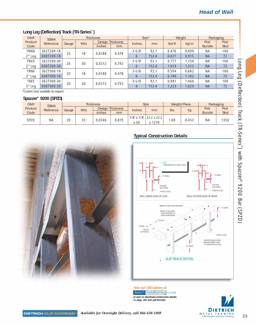
Dietrich Spazzer® 9200 is a prenotched, 20-gauge,galvanized steel spacer bar engineered to handle deflectionat the head track of interior, nonload-bearing,nonstructural stud walls. The prenotched slots andgripping power of the 50-inch bar holds studs into a rigid,accurately laid out gridwork that has excellent resistance tostud rotation and displacement. The Spazzer® 9200 spacerbar saves time and material by eliminating the cost ofcustom head tracks and the time required to fasten andremove screws or layout stud spacing at the deck. Hangingdrywall is also faster and easier because the Spazzer® 9200spacer bar eliminates the bow that often occurs in tallinterior studs.
Alternative ProductsSLP-TRK® Slotted Slip Track, Spazzer® 5400, Fast Top™ Clip
Product Dimensions7/8" by 7/8" by 50" long (22.2mm x 22.2mm x 1270mm)prenotched for 16" and 24" centers.
Long LegTrack
Spazzer® 9200
50"
7/8"7/8"The Spazzer® 9200 Spacing Barin conjunction with long legtrack provides a rapidlyinstalled, prenotched,prespaced interiordeflection systemthat saves time andeliminates materials.
Long
Leg
(D
efle
ctio
n) T
rack
(TR
-Ser
ies™
) w
ith S
pazz
er®
9200
Bar
(SP
ZD)
081016 DMF Catalog 18-39.qxd:Pgs 18-39 6/24/10 3:32 PM Page 22
23Available for Overnight Delivery, call 866-638-1908
Typical Construction Details
dietrich metalframing •comto view or download construction details in .dwg, .dxf, and .pdf formats.
Visit our CAD Library at
Head of Wall
DMF SSMA Thickness Size* Weight PackagingProduct Reference Gauge Mils Design Thickness Inches mm lbs/ft kg/m Pcs/ Pcs/Code Inches mm Bundle SkidTRND 362T200-18
25 18 0.0188 0.4783-5/8 92.1 0.470 0.699 NA 100
2" Leg 600T200-18 6 152.4 0.617 0.915 NA 72TRED 362T200-30
20 30 0.0312 0.7923-5/8 92.1 0.777 1.154 NA 100
2" Leg 600T200-30 6 152.4 1.019 1.512 NA 72TRNF 362T300-18
25 18 0.0188 0.4783-5/8 92.1 0.594 0.882 NA 100
3" Leg 600T300-18 6 152.4 0.740 1.102 NA 72TREF 362T300-30
20 30 0.0312 0.7923-5/8 92.1 0.981 1.460 NA 100
3" Leg 600T300-30 6 152.4 1.223 1.820 NA 72*Custom sizes available on request.
Long Leg (Deflection) Track (TR-Series™)
DMF SSMA Thickness Size Weight/Piece PackagingProduct Reference Gauge Mils Design Thickness Inches mm lbs kg Pcs/ Pcs/Code Inches mm Bundle Skid
SPZD NA 20 33 0.0346 0.8797/8 x 7/8 22.2 x 22.2
1.00 0.452 NA 1350x 50 x 1270
Spazzer® 9200 (SPZD)
Long Leg (Deflection) Track (TR-Series
™) with Spazzer ®
9200 Bar (SPZD)
081016 DMF Catalog 18-39.qxd:Pgs 18-39 6/24/10 3:32 PM Page 23
24
■ Vertical deflection up to 1-1/2" (3/4" up and 3/4" down) when using 2" long leg track.
■ Greater deflection can be achieved byincreasing length of long leg track andreducing stud height.
■ Eliminates high material cost of custom-madehead tracks.
■ Requires only a single generic long leg trackto provide deflection.
■ Facilitates sprayable intumescent/elastomericfirestops.
■ Eliminates stud spacing layout at deck.
■ Automatically positions and holds studs rigidlyon 12", 16" or 24" spacing.
dietrich metalframing •com The place to stop…before the building starts! SMrequest a quote online @
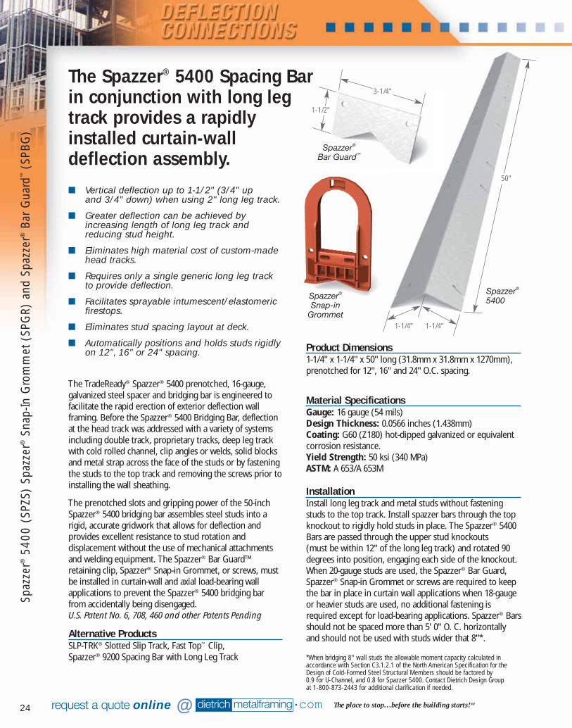
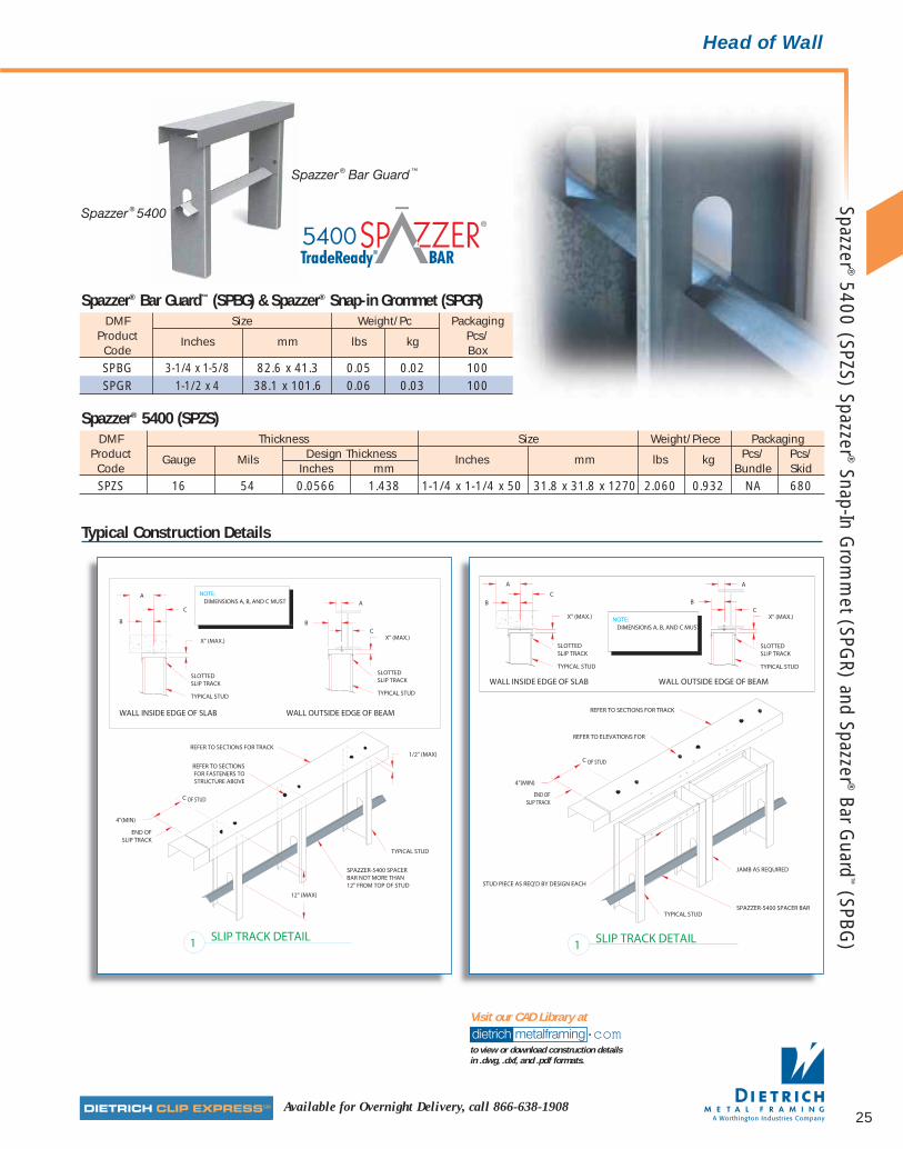
The TradeReady® Spazzer® 5400 prenotched, 16-gauge,galvanized steel spacer and bridging bar is engineered tofacilitate the rapid erection of exterior deflection wallframing. Before the Spazzer® 5400 Bridging Bar, deflectionat the head track was addressed with a variety of systemsincluding double track, proprietary tracks, deep leg trackwith cold rolled channel, clip angles or welds, solid blocksand metal strap across the face of the studs or by fasteningthe studs to the top track and removing the screws prior toinstalling the wall sheathing.
The prenotched slots and gripping power of the 50-inchSpazzer® 5400 bridging bar assembles steel studs into arigid, accurate gridwork that allows for deflection andprovides excellent resistance to stud rotation anddisplacement without the use of mechanical attachmentsand welding equipment. The Spazzer® Bar Guard™retaining clip, Spazzer® Snap-in Grommet, or screws, mustbe installed in curtain-wall and axial load-bearing wallapplications to prevent the Spazzer® 5400 bridging barfrom accidentally being disengaged.U.S. Patent No. 6, 708, 460 and other Patents Pending
Alternative ProductsSLP-TRK® Slotted Slip Track, Fast Top™ Clip, Spazzer® 9200 Spacing Bar with Long Leg Track
The Spazzer® 5400 Spacing Barin conjunction with long legtrack provides a rapidlyinstalled curtain-walldeflection assembly.
Product Dimensions1-1/4" x 1-1/4" x 50" long (31.8mm x 31.8mm x 1270mm),prenotched for 12", 16" and 24" O.C. spacing.
Material SpecificationsGauge: 16 gauge (54 mils)Design Thickness: 0.0566 inches (1.438mm)Coating: G60 (Z180) hot-dipped galvanized or equivalentcorrosion resistance.Yield Strength: 50 ksi (340 MPa)ASTM: A 653/A 653M
InstallationInstall long leg track and metal studs without fasteningstuds to the top track. Install spazzer bars through the topknockout to rigidly hold studs in place. The Spazzer® 5400Bars are passed through the upper stud knockouts (must be within 12" of the long leg track) and rotated 90degrees into position, engaging each side of the knockout.When 20-gauge studs are used, the Spazzer® Bar Guard,Spazzer® Snap-in Grommet or screws are required to keepthe bar in place in curtain wall applications when 18-gaugeor heavier studs are used, no additional fastening isrequired except for load-bearing applications. Spazzer® Barsshould not be spaced more than 5' 0" O. C. horizontallyand should not be used with studs wider that 8"*.
*When bridging 8" wall studs the allowable moment capacity calculated in accordance with Section C3.1.2.1 of the North American Specification for theDesign of Cold-Formed Steel Structural Members should be factored by 0.9 for U-Channel, and 0.8 for Spazzer 5400. Contact Dietrich Design Group at 1-800-873-2443 for additional clarification if needed.
Spazzer®
Bar Guard™
3-1/4"
1-1/2"
Spaz
zer®
5400
(SP
ZS)
Spaz
zer®
Snap
-In G
rom
met
(SP
GR)
and
Spa
zzer
®Ba
r G
uard
™(S
PBG
)
50"
1-1/4" 1-1/4"
Spazzer®
5400Spazzer®
Snap-inGrommet
081016 DMF Catalog 18-39.qxd:Pgs 18-39 6/24/10 3:32 PM Page 24
25Available for Overnight Delivery, call 866-638-1908
Typical Construction Details
dietrich metalframing •comto view or download construction details in .dwg, .dxf, and .pdf formats.
Visit our CAD Library at
Head of Wall
DMF Thickness Size Weight/Piece PackagingProduct Gauge Mils Design Thickness Inches mm lbs kg Pcs/ Pcs/Code Inches mm Bundle SkidSPZS 16 54 0.0566 1.438 1-1/4 x 1-1/4 x 50 31.8 x 31.8 x 1270 2.060 0.932 NA 680
Spazzer® 5400 (SPZS)
DMF Size Weight/Pc PackagingProduct Inches mm lbs kg Pcs/Code BoxSPBG 3-1/4 x 1-5/8 82.6 x 41.3 0.05 0.02 100SPGR 1-1/2 x 4 38.1 x 101.6 0.06 0.03 100
Spazzer® Bar Guard™ (SPBG) & Spazzer® Snap-in Grommet (SPGR)
Spazzer ® Bar Guard ™
Spazzer ® 5400
Spazzer ®5400 (SPZS) Spazzer ®
Snap-In Grom
met (SPG
R) and Spazzer ®Bar G
uard™
(SPBG)
081016 DMF Catalog 18-39.qxd:Pgs 18-39 6/24/10 3:32 PM Page 25
26 dietrich metalframing •com The place to stop…before the building starts! SMrequest a quote online @
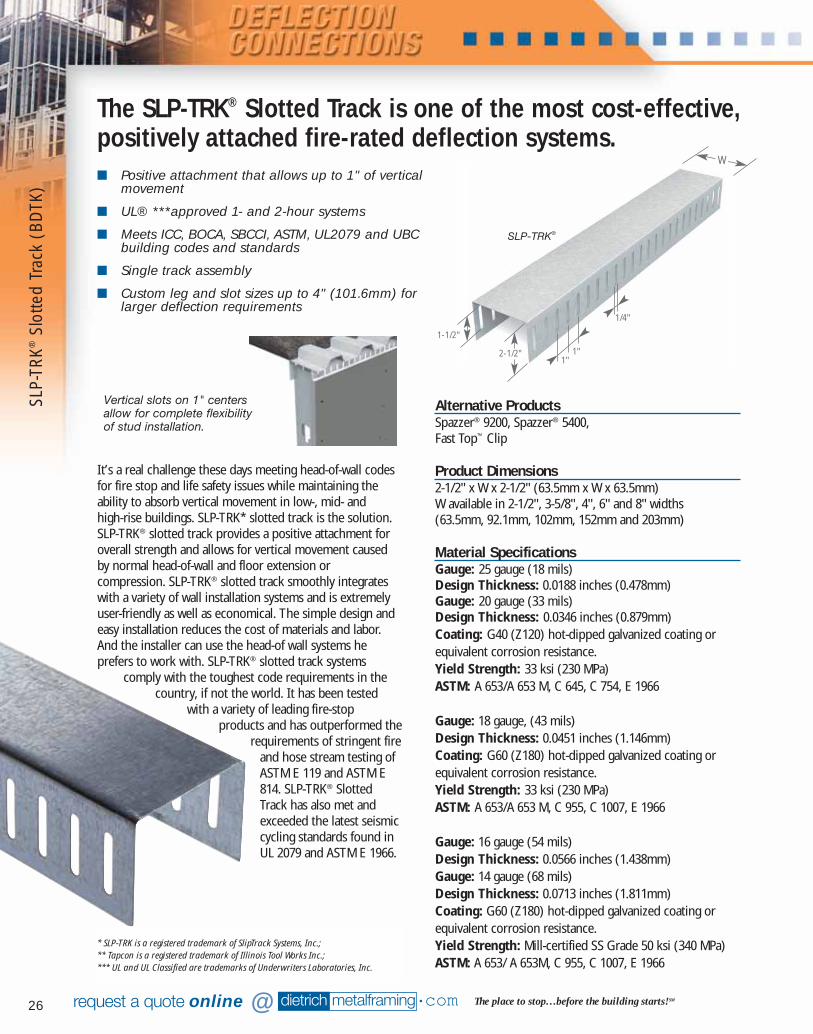
SLP-
TRK®
Slot
ted
Trac
k (B
DTK
)
■ Positive attachment that allows up to 1" of verticalmovement
■ UL® ***approved 1- and 2-hour systems
■ Meets ICC, BOCA, SBCCI, ASTM, UL2079 and UBCbuilding codes and standards
■ Single track assembly
■ Custom leg and slot sizes up to 4" (101.6mm) forlarger deflection requirements
It’s a real challenge these days meeting head-of-wall codesfor fire stop and life safety issues while maintaining theability to absorb vertical movement in low-, mid- and high-rise buildings. SLP-TRK* slotted track is the solution.SLP-TRK® slotted track provides a positive attachment foroverall strength and allows for vertical movement causedby normal head-of-wall and floor extension orcompression. SLP-TRK® slotted track smoothly integrateswith a variety of wall installation systems and is extremelyuser-friendly as well as economical. The simple design andeasy installation reduces the cost of materials and labor.And the installer can use the head-of wall systems heprefers to work with. SLP-TRK® slotted track systems
comply with the toughest code requirements in thecountry, if not the world. It has been tested
with a variety of leading fire-stopproducts and has outperformed the
requirements of stringent fireand hose stream testing ofASTM E 119 and ASTM E814. SLP-TRK® SlottedTrack has also met andexceeded the latest seismiccycling standards found inUL 2079 and ASTM E 1966.
SLP-TRK®
The SLP-TRK® Slotted Track is one of the most cost-effective,positively attached fire-rated deflection systems.
1/4"
2-1/2"
1-1/2"
1"1"
Vertical slots on 1" centersallow for complete flexibilityof stud installation.
W
* SLP-TRK is a registered trademark of SlipTrack Systems, Inc.;** Tapcon is a registered trademark of Illinois Tool Works Inc.;*** UL and UL Classified are trademarks of Underwriters Laboratories, Inc.
Alternative ProductsSpazzer® 9200, Spazzer® 5400, Fast Top™ Clip
Product Dimensions2-1/2" x W x 2-1/2" (63.5mm x W x 63.5mm)W available in 2-1/2", 3-5/8", 4", 6" and 8" widths(63.5mm, 92.1mm, 102mm, 152mm and 203mm)
Material SpecificationsGauge: 25 gauge (18 mils)Design Thickness: 0.0188 inches (0.478mm)Gauge: 20 gauge (33 mils)Design Thickness: 0.0346 inches (0.879mm)Coating: G40 (Z120) hot-dipped galvanized coating orequivalent corrosion resistance.Yield Strength: 33 ksi (230 MPa)ASTM: A 653/A 653 M, C 645, C 754, E 1966
Gauge: 18 gauge, (43 mils)Design Thickness: 0.0451 inches (1.146mm)Coating: G60 (Z180) hot-dipped galvanized coating orequivalent corrosion resistance.Yield Strength: 33 ksi (230 MPa)ASTM: A 653/A 653 M, C 955, C 1007, E 1966
Gauge: 16 gauge (54 mils)Design Thickness: 0.0566 inches (1.438mm)Gauge: 14 gauge (68 mils)Design Thickness: 0.0713 inches (1.811mm)Coating: G60 (Z180) hot-dipped galvanized coating orequivalent corrosion resistance.Yield Strength: Mill-certified SS Grade 50 ksi (340 MPa)ASTM: A 653/ A 653M, C 955, C 1007, E 1966
081016 DMF Catalog 18-39.qxd:Pgs 18-39 6/24/10 3:32 PM Page 26

27Available for Overnight Delivery, call 866-638-1908
Head of Wall
Code ApprovalsThe SLP-TRK® slotted track has achieved or meets the followingbuilding code approvals and requirements:• ICBO – ESR 1042• UL Classified R19236• UL Certified for Canada XHL17• LA City RR25344• OSHPD R#0371• NY City MEA 285-01-M• National Build Code of Canada.
InstallationInstall slotted track at the head of wall. Secure studs toslotted top track with #8 wafer-head screws. Be sure tosecure the studs to the track by screwing through the trackslots for a positive connection. Maintain a minimumdeflection gap of 5/8" (16.5mm) between top of stud andtop of slotted track. For fire-rated construction joints, usingthe approved system, install the drywall and other fire-ratedmaterials to the wall and complete the assembly.NOTE: No mixing of approved brand namecomponents in the assembly is allowed.
DMF Thickness Size*** Weight PackagingProduct Gauge Mils Design Thickness Inches mm lbs/ft kg/m Pcs/ Pcs/Code Inches mm Bundle Skid
2-1/2 63.5 0.484 0.718 1123-5/8 92.1 0.556 0.826 100
BDTK 25 18 0.0188 0.478 4 101.6 0.580 0.859 906 152.4 0.708 1.050 608 203.2 0.836 1.240 50
2-1/2 63.5 0.882 1.309 1123-5/8 92.1 1.015 1.505 100
BDTK 20 33 0.0346 0.879 4 101.6 1.059 1.571 906 152.4 1.294 1.922 608 203.2 1.529 2.270 50
2-1/2 63.5 1.150 1.706 1123-5/8 92.1 1.323 1.965 100
BDTK 18 43 0.0451 1.146 4 101.6 1.380 2.047 N/A 906 152.4 1.687 2.503 608 203.2 1.993 2.959 50
2-1/2 63.5 1.443 2.142 1123-5/8 92.1 1.660 2.463 100
BDTK 16 54 0.0566 1.438 4 101.6 1.732 2.571 906 152.4 2.117 3.142 608 203.2 2.502 3.713 50
2-1/2 63.5 1.818 2.699 1123-5/8 92.1 2.091 3.103 100
BDTK 14 68 0.0713 1.811 4 101.6 2.182 3.237 906 152.4 2.667 3.959 608 203.2 3.152 4.677 50
* SLP-TRK is a registered trademark of SlipTrack Systems, Inc. ** UL and UL Classified are trademarks of Underwriters Laboratories, Inc.*** Custom sizes available upon request. ∅ This product is not delivered via the Dietrich Clip Express Service
SLP-TRK® Slotted Track (BDTK)
"P = the maximum horizontal force allowed at the top of the stud for all cases. Please note that the seismic load for the weight of the wall itself and equipment attached to the wall is not required to be additive with 5 psfinterior partition wall lateral load (they are separate load cases).
SLP-TRK® Slotted Track Allowable Loads
Table Notes
1) Fire-rated assemblies shall comply to UL 2079Test Standard
2) Load data based on Twining Laboratories LoadTest #95-9080 / 9/11/1995
3) Sliptrack Systems Slotted Track – SLP-TRK®
4) Track is 14, 16, 18 & 20 Gauge5) Fy = 50 ksi for 14 and 16 gauge members;
Fy = 33 ksi for 18 and 20 gauge members6) SLP-TRK® Single Track Systems: A second top
track is not required7) The connection of the track to the structure is
a minimum standard. The engineer of recordfor a site-specific project is responsible for thedesign of the connection to the structure.
8) Minimum 5/8" (16.5mm) space requirementfor deflection
9) Partition studs at 12", 16", or 24" o/c typically.Studs attached to tracks with #8 x 9/16"wafer head screws
10) For larger details or CAD downloads visitwww.dietrichmetalframing.com
11) One- and two-hour fire rated designs aretested perpendicular to the fluted deck per UL-2079 test standard. For various fire-ratedinstallation conditions, referencewww.bradyinnovations.com and obtain site-specific approval from the Project Architectand Building Official having jurisdiction. Submitdata and installation details via the projectsubmittal process prior to field installations.
Typical Construction Details
dietrich metalframing •comview or download construction details in .dwg, .dxf, and .pdf formats.
Over 60 SLP-TRK CAD Details Available on
20 Gauge SLP-TRK® 16 Gauge SLP-TRK®
P = 166 lbs P = 314 lbs
18 Gauge SLP-TRK® 14 Gauge SLP-TRK®
P = 196 lbs P = 314+ lbs
SLP-TRK®
Slotted Track (BD
TK)
081016 DMF Catalog 18-39.qxd:Pgs 18-39 6/24/10 3:32 PM Page 27

dietrich metalframing •com The place to stop…before the building starts! SMrequest a quote online @28
System 1 – W.R. GraceWHI-495-PSV-1201
System 2 – W.R. GraceWHI-495-PSV-1333
System 3 – IsolatekWHI-495-PSV-1333
System 4 – IsolatekWHI-495-PSV-1334
System 5 – IsolatekWHI-495-PSV-1333
System 6 – W.R. GraceWHI-495-PSV-1338
SLP-TRK® Systems — Fire-Rated AssembliesSystem 1–6 Warnok Hersey/ITS ICBO ESR-1042
System 7STI
UL-HW-D-0003UL-HW-D-0034UL-HW-D-0043UL-HW-D-0044UL-HW-D-0054UL-HW-D-0079UL-HW-D-0088UL-HW-D-0099UL-HW-D-0102UL-HW-D-0136UL-HW-D-0137UL-HW-D-0152UL-HW-D-0153UL-HW-D-0194UL-HW-D-0210UL-HW-D-0241UL-HW-D-0242UL-HW-D-0243UL-HW-D-0260UL-HW-D-0363UL-HW-D-0365UL-HW-D-0371
System 8PFPP
UL-HW-D-0024UL-HW-D-0025UL-HW-D-0036UL-HW-D-0062UL-HW-D-0063UL-HW-D-0071UL-HW-D-0072UL-HW-D-0073UL-HW-D-0162UL-HW-D-0185UL-HW-D-0191UL-HW-D-0271UL-HW-D-0272UL-HW-D-0263UL-HW-D-0278
System 93M
UL-HW-D-0020UL-HW-D-0021UL-HW-D-0029UL-HW-D-0031UL-HW-D-0101UL-HW-D-0111UL-HW-D-0134UL-HW-D-0170UL-HW-D-0173UL-HW-D-0205UL-HW-D-0265
System 10HILTI
UL-HW-D-0042UL-HW-D-0045UL-HW-D-0046UL-HW-D-0049UL-HW-D-0076UL-HW-D-0077UL-HW-D-0082UL-HW-D-0083UL-HW-D-0084UL-HW-D-0085UL-HW-D-0087UL-HW-D-0089UL-HW-D-0106UL-HW-D-0154UL-HW-D-0184UL-HW-D-0190UL-HW-D-0218UL-HW-D-0259UL-HW-D-0313UL-HW-D-0321UL-HW-D-0322UL-HW-D-0324
System 11Johns-ManvilleUL-HW-D-0047UL-HW-D-0048UL-HW-D-0067UL-HW-D-0068UL-HW-D-0069UL-HW-D-0167UL-HW-D-0186UL-HW-D-0193UL-HW-D-0195UL-HW-D-0275UL-HW-D-0277
System 12Rectorseal
UL-HW-D-0032UL-HW-D-0033UL-HW-D-0058UL-HW-D-0059UL-HW-D-0104UL-HW-D-0105UL-HW-D-0127UL-HW-D-0128UL-HW-D-0129UL-HW-D-0130UL-HW-D-0179UL-HW-D-0180UL-HW-D-0221UL-HW-D-0222UL-HW-D-0297UL-HW-D-0298
System 13GRACE-Flamesafe
UL-HW-D-0107UL-HW-D-0108UL-HW-D-0124UL-HW-D-0144UL-HW-D-0146UL-HW-D-0147UL-HW-D-0148UL-HW-D-0165UL-HW-D-0213UL-HW-D-0217UL-HW-D-0219UL-HW-D-0257UL-HW-D-0299
System 14EGS Nelson
UL-HW-D-0223UL-HW-D-0224UL-HW-D-0227UL-HW-D-0228UL-HW-D-0238UL-HW-D-0239UL-HW-D-0283UL-HW-D-0288UL-HW-D-0304UL-HW-D-0305UL-HW-D-0309UL-HW-D-0310
System 15Tremco
UL-HW-D-0016UL-HW-D-0091UL-HW-D-0255UL-HW-D-0256UL-HW-D-0291
System 16JohnWagner Assoc.
UL-HW-D-0353UL-HW-D-0356UL-HW-D-0357UL-HW-D-0358UL-HW-D-0368UL-HW-D-0370
System 17A/D Fire Protection
Systems UL-HW-D-0247UL-HW-D-0249UL-HW-D-0314UL-HW-D-0315UL-HW-D-0316UL-HW-D-0317UL-HW-D-0320
System 18OSI Sealants Inc.UL-HW-D-0183UL-HW-D-0341
System 19USG
UL-HW-D-0160
= ShaftwallSystem
Sliptrack® SystemSliptrack has been designed to be used with multiple fire-proof materials. Below is a sequence of photographs illustrating atypical installation using chemical fire-resistive sealants (courtesy of Specified Technologies Inc.)
Mineral wool is placed in the flutedmetal deck after the drywall is installed
The deflection gap is filled with mineral wool.
The head-of-wall construction joint issprayed with fire resistive sealant.
SLP-
TRK®
Slot
ted
Trac
k (B
DTK
)
081016 DMF Catalog 18-39.qxd:Pgs 18-39 6/24/10 3:32 PM Page 28
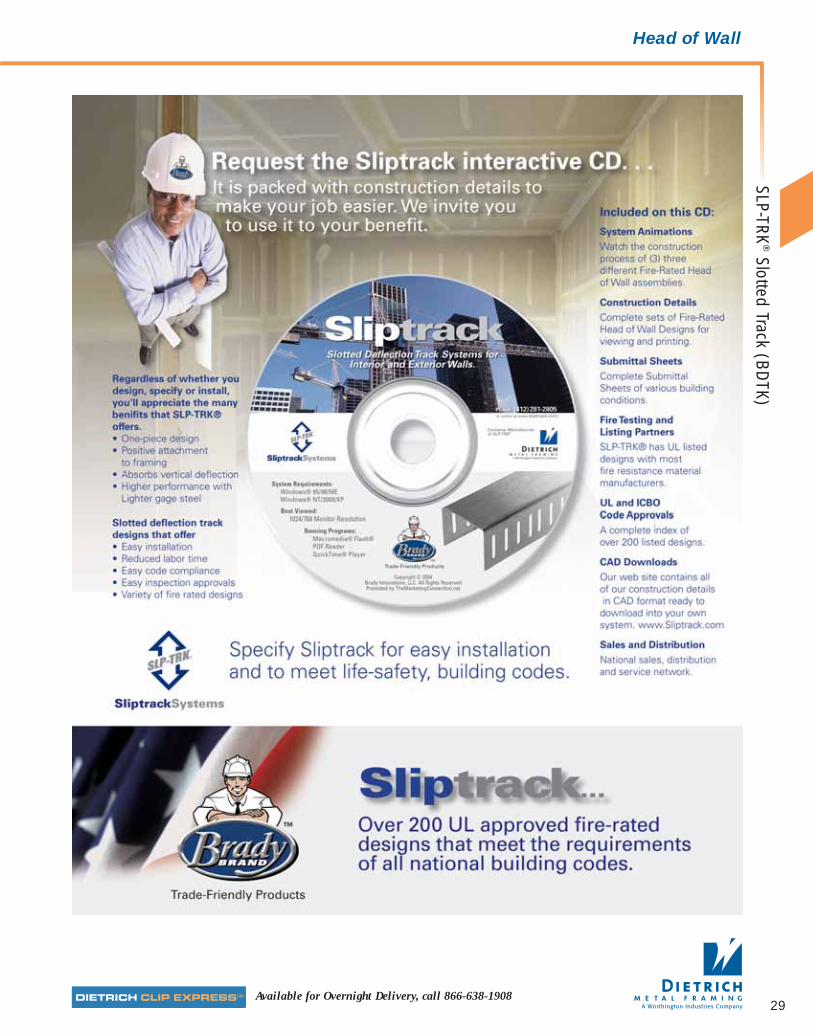
Available for Overnight Delivery, call 866-638-1908
Head of Wall
29
SLP-TRK®
Slotted Track (BD
TK)
081016 DMF Catalog 18-39.qxd:Pgs 18-39 6/24/10 3:32 PM Page 29
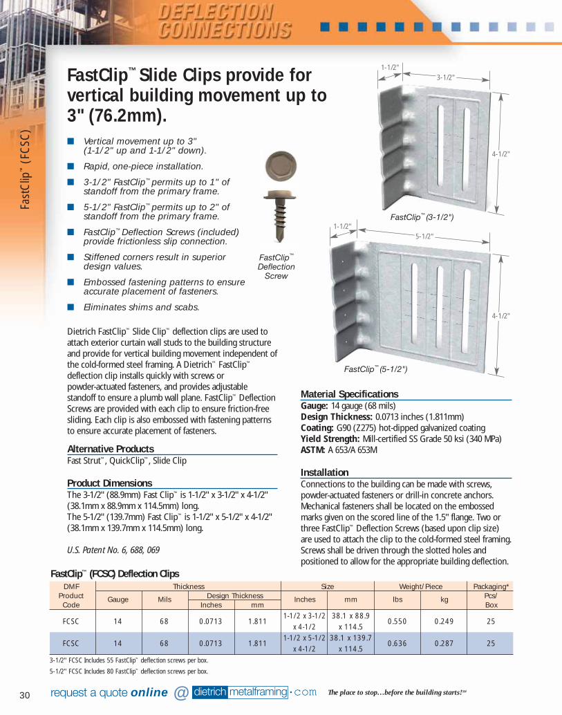
30
■ Vertical movement up to 3" (1-1/2" up and 1-1/2" down).
■ Rapid, one-piece installation.
■ 3-1/2" FastClip™ permits up to 1" ofstandoff from the primary frame.
■ 5-1/2" FastClip™ permits up to 2" ofstandoff from the primary frame.
■ FastClip™ Deflection Screws (included)provide frictionless slip connection.
■ Stiffened corners result in superiordesign values.
■ Embossed fastening patterns to ensureaccurate placement of fasteners.
■ Eliminates shims and scabs.
dietrich metalframing •com The place to stop…before the building starts! SMrequest a quote online @
Material SpecificationsGauge: 14 gauge (68 mils)Design Thickness: 0.0713 inches (1.811mm)Coating: G90 (Z275) hot-dipped galvanized coatingYield Strength: Mill-certified SS Grade 50 ksi (340 MPa)ASTM: A 653/A 653M
InstallationConnections to the building can be made with screws,powder-actuated fasteners or drill-in concrete anchors.Mechanical fasteners shall be located on the embossedmarks given on the scored line of the 1.5" flange. Two orthree FastClip™ Deflection Screws (based upon clip size)are used to attach the clip to the cold-formed steel framing.Screws shall be driven through the slotted holes andpositioned to allow for the appropriate building deflection.
Dietrich FastClip™ Slide Clip™ deflection clips are used toattach exterior curtain wall studs to the building structureand provide for vertical building movement independent ofthe cold-formed steel framing. A Dietrich™ FastClip™
deflection clip installs quickly with screws or powder-actuated fasteners, and provides adjustablestandoff to ensure a plumb wall plane. FastClip™ DeflectionScrews are provided with each clip to ensure friction-freesliding. Each clip is also embossed with fastening patternsto ensure accurate placement of fasteners.
Alternative ProductsFast Strut™, QuickClip™, Slide Clip
Product DimensionsThe 3-1/2" (88.9mm) Fast Clip™ is 1-1/2" x 3-1/2" x 4-1/2"(38.1mm x 88.9mm x 114.5mm) long.The 5-1/2" (139.7mm) Fast Clip™ is 1-1/2" x 5-1/2" x 4-1/2"(38.1mm x 139.7mm x 114.5mm) long.
U.S. Patent No. 6, 688, 069
FastClip™ Slide Clips provide forvertical building movement up to3" (76.2mm).
FastClip™ (3-1/2")
FastClip™ (5-1/2")
FastClip™
DeflectionScrew
DMF Thickness Size Weight/Piece Packaging*Product Gauge Mils Design Thickness Inches mm lbs kg Pcs/Code Inches mm Box
FCSC 14 68 0.0713 1.8111-1/2 x 3-1/2 38.1 x 88.9
0.550 0.249 25x 4-1/2 x 114.5
FCSC 14 68 0.0713 1.8111-1/2 x 5-1/2 38.1 x 139.7
0.636 0.287 25x 4-1/2 x 114.5
3-1/2" FCSC Includes 55 FastClip™ deflection screws per box.
5-1/2" FCSC Includes 80 FastClip™ deflection screws per box.
FastClip™ (FCSC) Deflection Clips
4-1/2"
4-1/2"
5-1/2"
3-1/2"
1-1/2"
1-1/2"
Fast
Clip
™(F
CSC
)
081016 DMF Catalog 18-39.qxd:Pgs 18-39 6/24/10 3:32 PM Page 30
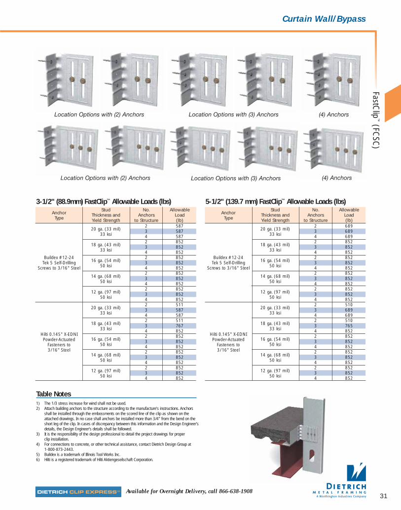
31
Curtain Wall/Bypass
Location Options with (2) Anchors Location Options with (3) Anchors (4) Anchors
Location Options with (2) Anchors Location Options with (3) Anchors (4) Anchors
Available for Overnight Delivery, call 866-638-1908
FastClip
™(FC
SC)
3-1/2" (88.9mm) FastClip™ Allowable Loads (lbs)Anchor
Stud No. Allowable
TypeThickness and Anchors LoadYield Strength to Structure (lb)
20 ga. (33 mil) 2 587
33 ksi3 5874 587
18 ga. (43 mil)2 852
33 ksi3 8524 852
Buildex #12-2416 ga. (54 mil)
2 852Tek 5 Self-Drilling
50 ksi3 852
Screws to 3/16" Steel 4 852
14 ga. (68 mil) 2 852
50 ksi3 8524 852
12 ga. (97 mil)2 852
50 ksi3 8524 852
20 ga. (33 mil) 2 511
33 ksi3 5874 587
18 ga. (43 mil)2 511
33 ksi3 767
Hilti 0.145" X-EDNI4 852
Powder-Actuated 16 ga. (54 mil)2 852
Fasteners to 50 ksi3 852
3/16" Steel4 852
14 ga. (68 mil) 2 852
50 ksi3 8524 852
12 ga. (97 mil)2 852
50 ksi3 8524 852
5-1/2" (139.7 mm) FastClip™ Allowable Loads (lbs)Anchor
Stud No. Allowable
TypeThickness and Anchors LoadYield Strength to Structure (lb)
20 ga. (33 mil) 2 689
33 ksi3 6894 689
18 ga. (43 mil)2 852
33 ksi3 8524 852
Buildex #12-2416 ga. (54 mil)
2 852Tek 5 Self-Drilling
50 ksi3 852
Screws to 3/16" Steel 4 852
14 ga. (68 mil) 2 852
50 ksi3 8524 852
12 ga. (97 mil)2 852
50 ksi3 8524 852
20 ga. (33 mil) 2 510
33 ksi3 6894 689
18 ga. (43 mil)2 510
33 ksi3 765
Hilti 0.145" X-EDNI4 852
Powder-Actuated 16 ga. (54 mil)2 852
Fasteners to 50 ksi3 852
3/16" Steel4 852
14 ga. (68 mil) 2 852
50 ksi3 8524 852
12 ga. (97 mil)2 852
50 ksi3 8524 852
Table Notes1) The 1/3 stress increase for wind shall not be used.2) Attach building anchors to the structure according to the manufacture’s instructions. Anchors
shall be installed through the embossments on the scored line of the clip as shown on theattached drawings. In no case shall anchors be installed more than 3/4" from the bend on theshort leg of the clip. In cases of discrepancy between this information and the Design Engineer’sdetails, the Design Engineer’s details shall be followed.
3) It is the responsibility of the design professional to detail the project drawings for properclip installation.
4) For connections to concrete, or other technical assistance, contact Dietrich Design Group at1-800-873-2443.
5) Buildex is a trademark of Illinois Tool Works Inc.6) Hilti is a registered trademark of Hilti Aktiengeseilschaft Corporation.
081016 DMF Catalog 18-39.qxd:Pgs 18-39 6/24/10 3:32 PM Page 31

32
■ Use for all medium and large standoff conditions.
■ Eliminates shims and scabs.
■ Vertical movement up to 3" (1-1/2" up and 1-1/2"down).
■ Specially designed to simplify welding installation
■ Fast, one-piece universal installation. No left or right handed clips.
■ FastClip™ Deflection Screws(included) provide frictionless slip connections.
■ Custom and longer lengths available
dietrich metalframing •com The place to stop…before the building starts! SMrequest a quote online @
1-7/8" x 10" x 4-3/4"(47.6mm x 254.0mm x 120.6mm) long.The 12" (304.8mm) EXTENDED FastClip™ is 1-7/8" x 12” x 4-3/4"(47.6mm x 304.8mm x 120.6mm) long.
Material SpecificationsGauge: 14 gauge (68 mils)Design Thickness: 0.0713 inches (1.811mm)Coating: G90 (Z275) hot-dipped galvanized coating.Yield Strength: Mill-certified SS Grade 50 ksi (340 MPa)ASTM: A 653/A 653M
InstallationConnections to the building can be made with screws,welds powder-actuated fasteners or drill-in concreteanchors. Mechanical fasteners shall be located on theembossed marks given on the scored line of the 1-7/8"flange. Attach building anchors to the structure accordingto the manufacture’s instructions. Anchors shall be installedthrough the embossments on the scored line of the clip asshown on the attached drawings. In no case shall anchors beinstalled more than 3/4" from the bend on the short leg of theclip. In cases of discrepancy between this information and theDesign Engineer’s details, the Design Engineer’s details shallbe followed. Three FastClip™ Deflection Screws are used toattach the clip to the cold-formed steel framing. Screwsshall be driven through the slotted holes and positionedto allow for the appropriate building deflection.
U.S. Patent No. 6, 688, 069
Dietrich EXTENDED FastClip™ Slide Clip™ deflection clips areused to attach exterior curtain wall studs to the buildingstructure and provide for vertical building movementindependent of the cold-formed steel framing. The clips areavailable in standard lengths of 8”, 10” and 12” and are idealfor medium to larger standoff conditions. EXTENDEDFastClip™ deflection clips install quickly with screws, welds orpowder-actuated fasteners, and provide adjustable standoff toensure a plumb wall plane. FastClip™ Deflection Screws areprovided with each clip to ensure friction-free sliding.
Alternative ProductsFast Strut™
Product DimensionsThe 8" (203.2mm) EXTENDED FastClip™ is 1-7/8" x 8" x 4-3/4"(47.6mm x 203.2mm x 120.6mm) long.The 10" (254.0mm) EXTENDED FastClip™ is
FastClip™
DeflectionScrew
EXTE
ND
ED F
astC
lip™
Slid
e C
lip™
(FC
EC)
DMF Thickness Size Weight/Piece Packaging*Product Gauge Mils Design Thickness Inches mm lbs kg Pcs/Code Inches mm Box
FCEC 14 68 0.0713 1.8111-7/8 x 8 47.6 x 203.2
1.092 0.495 25x 4-3/4 x 120.6
FCEC 14 68 0.0713 1.8111-7/8 x 10 47.6 x 254.0
1.366 0.619 25x 4-3/4 x 120.6
FCEC 14 68 0.0713 1.8111-7/8 x 12 47.6 x 304.8
1.639 0.743 25x 4-3/4 x 120.6
Includes 80 FastClip™ deflection screws per box.
EXTENDED FastClip™ (FCEC) Deflection Clips
4-3/4"
1/2"
1-7/8"
EXTENDED FastClip™
NEWITEM
8", 10" or 12"
The EXTENDED FastClip™ slide clip curtain wall deflectionconnector provides for vertical building movementup to 3” (76.2mm) and is commonly usedfor large standoff conditions.
081016 DMF Catalog 18-39.qxd:Pgs 18-39 6/24/10 3:32 PM Page 32

33Available for Overnight Delivery, call 866-638-1908
Curtain Wall/BypassEXTEN
DED
FastClip
™Slide C
lip™
(FCEC
)
EXTENDED FastClip™ Allowable Loads (lbs)
Location Options with (2) Anchors
Location Options with (3) Anchors
(4) Anchors
Table Notes1) The 1/3 stress increase for wind shall not be used.2) Attach building anchors to the structure according to the manufacture’s instructions. Anchors
shall be installed through the embossments on the scored line of the clip as shown on theattached drawings. In no case shall anchors be installed more than 3/4" from the bend on theshort leg of the clip. In cases of discrepancy between this information and the Design Engineer’sdetails, the Design Engineer’s details shall be followed.
3) It is the responsibility of the design professional to detail the project drawings for properclip installation.
4) For connections to concrete, or other technical assistance, contact Dietrich Design Group at1-800-873-2443.
5) Buildex is a trademark of Illinois Tool Works Inc.6) Hilti is a registered trademark of Hilti Aktiengeseilschaft Corporation.
AnchorStud No. Allowable
TypeThickness and Anchors LoadYield Strength to Structure (lb)
20 ga. (33 mil) 2 689
33 ksi3 6894 689
18 ga. (43 mil)2 852
33 ksi3 8524 852
Buildex #12-2416 ga. (54 mil)
2 852Tek 5 Self-Drilling
50 ksi3 852
Screws to 3/16" Steel 4 852
14 ga. (68 mil) 2 852
50 ksi3 8524 852
12 ga. (97 mil)2 852
50 ksi3 8524 852
20 ga. (33 mil) 2 689
33 ksi3 6894 689
18 ga. (43 mil)2 510
33 ksi3 765
Hilti 0.145" X-EDNI4 852
Powder-Actuated 16 ga. (54 mil)2 852
Fasteners to 50 ksi3 852
3/16" Steel4 852
14 ga. (68 mil) 2 852
50 ksi3 8524 852
12 ga. (97 mil)2 852
50 ksi3 8524 852
081016 DMF Catalog 18-39.qxd:Pgs 18-39 6/24/10 3:32 PM Page 33

34
■ Vertical movement up to 2-1/2"(63.5mm), 1-1/4" (31.8mm) up and1-1/4" (31.8mm) down).
■ Use for all large standoff conditions.
■ Fast, one-piece universal installation. No left or right handed clips.
■ FastClip™ Deflection Screws (included)provide frictionless slip connections.
■ Embossed fastening pattern toensure accurate placement offasteners.
■ Custom and longer lengths available.
dietrich metalframing •com The place to stop…before the building starts! SMrequest a quote online @
Material SpecificationsGauge: 14 gauge (68 mils)Design Thickness: 0.0713 inches (1.811mm)Coating: G90 (Z275) hot-dipped galvanized coating.Yield Strength: Mill-certified SS Grade 50 ksi (340 MPa)ASTM: A 653/A 653M
InstallationConnections to the building can be made with screws,powder-actuated fasteners, drill-in concrete anchors orwelding. Mechanical fasteners shall be equally spaced alongthe scored line of the 2" flange. The strut must engage thebuilding structure a minimum of 4". When using thetabulated allowable loads indicated in the table on thefollowing page, connections to the building structure mustbe made according to the table notes. Three FastClip™
Deflection Screws are used to attach the strut to the cold-formed steel framing. Screws shall be driven through theslotted holes and positioned to allow for the appropriatebuilding deflection.
U.S. Patent No. 6, 688, 069
The Dietrich Fast Strut™ curtain wall connector employsthe Fast Clip™ technology for curtain wall stud attachmentand is commonly used when large stand-off conditionsexist. Fast Strut™ products are available in standard lengthsof 12-1/4" and 15-1/4" and custom lengths of up to 24" long to allow framing attachment well beyond theperimeter of the structural steel or when the spandrelbeams are set back from the edge of the structure. Strutsare attached to the underside of structural members withscrews, welds or powder-actuated fasteners. Studs areplumbed and secured with propriety screws for friction-free deflection. Each clip is also embossed with fasteningpatterns to ensure accurate placement of fasteners.
Alternative ProductsFast Clip™, QuickClip™, Slide Clip
Product DimensionsFS12: 4" x 2" x 12-1/4" (102mm x 50.8mm x 311mm)FS15: 4" x 2" x 15-1/4" (102mm x 50.8mm x 387mm)FS24: 4" x 2" x 24" (102mm x 50.8mm x 610mm)
The Fast Strut™ curtain walldeflection connector is commonlyused for large standoff conditions.
DMF Thickness Size Weight/Piece Packaging*Product Gauge Mils Design Thickness Inches mm lbs kg Pcs/Code Inches mm BoxFS12 14 68 0.0713 1.811 4 x 2 x 12-1/4 102 x 50.8 x 311 1.560 0.706 10FS15 14 68 0.0713 1.811 4 x 2 x 15-1/4 102 x 50.8 x 387 1.970 0.891 10FS24 14 68 0.0713 1.811 4 x 2 x 24 102 x 50.8 x 610 3.060 1.371 10
*Includes 55 FastClip™ deflection screws per box.Custom lengths are available up to 24".
Fast Strut™ 12, 15 and 24 (FS12/FS15/FS24) Curtain-Wall Connector
Fast Strut™ 12
Fast Strut™ 15
12-1/4"
15-1/4"
4"
4"
2"
2"
FastClip™
DeflectionScrewFa
st S
trut™
(FS1
2, F
S15,
FS2
4)
081016 DMF Catalog 18-39.qxd:Pgs 18-39 6/24/10 3:32 PM Page 34

35Available for Overnight Delivery, call 866-638-1908
Curtain Wall/Bypass
1) Except when welding, tabulated values require a minimumof 4" of structure engagement. For other conditions ortechnical assistance, contact Dietrich Design Group at 1-800-873-2443.
2) The tabulated values for welds are based on the followingweld lengths: use 4.5" of weld along each edge of the1.5" FastStrut leg for 20, and 18 gage, use 5.5" alongeach edge for 16 and 14 gage, use 6.5" along each edgefor 12 gage. Use E60XX (min.) electrodes. (Note that the welded values may require more than 4" of structure engagement.)
3) Tabulated values for Hilti PAF's and Buildex screws arebased on the following: fasteners are spaced at 3" o/c(min.) when using 2 anchors, and 1.5" o/c (min.) whenusing 3 anchors, anchors are placed 1/2" (min.) away fromthe edge of the building structure, and 1/2" (min.) awayfrom edge of the Fast Strut.
4) Tabulated values for Hilti Kwik-Cons are based on thefollowing: anchors are spaced at 2.75" o/c (min.), anchorsare placed 3/4" (min.) away from edge of building structureand 1/2" (min.) away from edge of Fast Strut. Thetabulated values are based on 3000 psi concrete.
5) For 3/4" deflection, center the proprietary screws along thetop most hash mark. For 1.25" deflection, center thescrews along the center hash-mark.
6) The values given for PAF's are based on Hilti X-EDNI0.145" Dia. powder actuated fasteners with 15 mm washers.
7) It is the responsibility of the design professional to detail theproject drawings for proper clip attachment.
dietrich metalframing •comto view or download construction details in .dwg, .dxf, and .pdf formats.
Visit our CAD Library at
Table Notes
Stud Welded Mechanically AnchoredThickness Slip Direct to Number
Hilti HiltiBuildex
Hiltiand Allowance Structural of
PAF in PAF in#12-24
1/4" xYield (Inches) Steel Anchors
Steel SteelScrews
1-3/4"Strength (FS=5) (FS=10) Kwik-Cons
20 ga. 0.75546 2 546 290 546 273
(33 mil) 546 3 546 343 546 ---
33 ksi 1.25546 2 513 257 546 235546 3 546 294 546 ---
18 ga. 0.751522 2 579 290 791 273
(43 mil) 1522 3 686 343 966 ---
33 ksi 1.251522 2 513 257 722 2351522 3 587 294 853 ---
16 ga. 0.751612 2 579 290 791 273
(54 mil) 1612 3 686 343 966 ---
33 ksi 1.251612 2 513 257 722 2351612 3 587 294 853 ---
16 ga. 0.751705 2 579 290 791 273
(54 mil) 1705 3 686 343 966 ---
50 ksi 1.251705 2 513 257 722 2351705 3 587 294 853 ---
14 ga. 0.751792 2 579 290 791 273
(68 mil) 1792 3 686 343 966 ---
33 ksi 1.251792 2 513 257 722 2351792 3 587 294 853 ---
14 ga. 0.751978 2 579 290 791 273
(68 mil) 1978 3 686 343 966 ---
50 ksi 1.251978 2 513 257 722 2351978 3 587 294 853 ---
12 ga. 0.752481 2 579 290 791 273
(97 mil) 2481 3 686 343 966 ---
33 ksi 1.252481 2 513 257 722 2352481 3 587 294 853 ---
12 ga. 0.752997 2 579 290 791 273
(97 mil) 2997 3 686 343 966 ---
50 ksi 1.252997 2 513 257 722 2352997 3 587 294 853 ---
FS12, FS15 and FS24 — Allowable Loads (lbs)
Typical Construction Details
Fast Strut ™(FS12, FS15, FS24)
081016 DMF Catalog 18-39.qxd:Pgs 18-39 6/24/10 3:32 PM Page 35
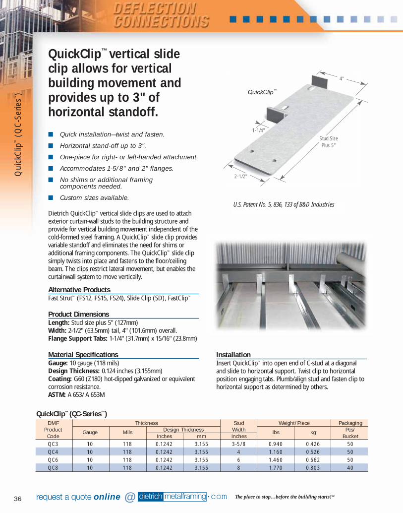
36
■ Quick installation—twist and fasten.
■ Horizontal stand-off up to 3".
■ One-piece for right- or left-handed attachment.
■ Accommodates 1-5/8" and 2" flanges.
■ No shims or additional framing components needed.
■ Custom sizes available.
dietrich metalframing •com The place to stop…before the building starts! SMrequest a quote online @
Dietrich QuickClip™ vertical slide clips are used to attachexterior curtain-wall studs to the building structure andprovide for vertical building movement independent of thecold-formed steel framing. A QuickClip™ slide clip providesvariable standoff and eliminates the need for shims oradditional framing components. The QuickClip™ slide clipsimply twists into place and fastens to the floor/ceilingbeam. The clips restrict lateral movement, but enables thecurtainwall system to move vertically.
Alternative ProductsFast Strut™ (FS12, FS15, FS24), Slide Clip (SD), FastClip™
Product DimensionsLength: Stud size plus 5" (127mm)Width: 2-1/2" (63.5mm) tail, 4" (101.6mm) overall. Flange Support Tabs: 1-1/4" (31.7mm) x 15/16" (23.8mm)
Material SpecificationsGauge: 10 gauge (118 mils)Design Thickness: 0.124 inches (3.155mm)Coating: G60 (Z180) hot-dipped galvanized or equivalentcorrosion resistance.ASTM: A 653/ A 653M
QuickClip™ vertical slideclip allows for verticalbuilding movement andprovides up to 3" ofhorizontal standoff.
QuickClip™
U.S. Patent No. 5, 836, 133 of B&D Industries
DMF Thickness Stud Weight/Piece PackagingProduct Gauge Mils Design Thickness Width lbs kg Pcs/Code Inches mm Inches BucketQC3 10 118 0.1242 3.155 3-5/8 0.940 0.426 50QC4 10 118 0.1242 3.155 4 1.160 0.526 50QC6 10 118 0.1242 3.155 6 1.460 0.662 50QC8 10 118 0.1242 3.155 8 1.770 0.803 40
QuickClip™ (QC-Series™)
InstallationInsert QuickClip™ into open end of C-stud at a diagonaland slide to horizontal support. Twist clip to horizontalposition engaging tabs. Plumb/align stud and fasten clip tohorizontal support as determined by others.
Stud SizePlus 5"
2-1/2"
4"
1-1/4"
Qui
ckC
lip™
(QC
-Ser
ies™
)
081016 DMF Catalog 18-39.qxd:Pgs 18-39 6/24/10 3:32 PM Page 36

37Available for Overnight Delivery, call 866-638-1908
Curtain Wall/Bypass
Table Notes
1) Tabulated values do not include the 1/3 stress increase.2) The Quick-Clip is not recommended for use in areas controlled by seismic.3) Tabulated values are based on 1" of weld to the structural steel on each side of the Quick-Clip.
Use E60XX electrodes.4) For technical service call Dietrich Design Group at 1-800-873-2443.
dietrich metalframing •comto view or download construction details in .dwg, .dxf, and .pdf formats.
Visit our CAD Library at
Typical Construction Details
QuickC
lip™
(QC
-Series™)
Stud Type/Flange Width Stud GaugeMin Thickness Yield Strength Allowable
(Inches) Fy (ksi) Load (lbs)20 0.0329 33 27718 0.0428 33 469
16 0.053833 476
CSJ / 1.625"50 722
14 0.067733 75450 837
12 0.096633 83750 837
20 0.0329 33 8418 0.0428 33 151
16 0.053833 166
CSW / 2"50 252
14 0.067733 29350 444
12 0.096633 70250 837
Allowable Loads for the 10 Gauge QuickClip™
081016 DMF Catalog 18-39.qxd:Pgs 18-39 6/24/10 3:32 PM Page 37
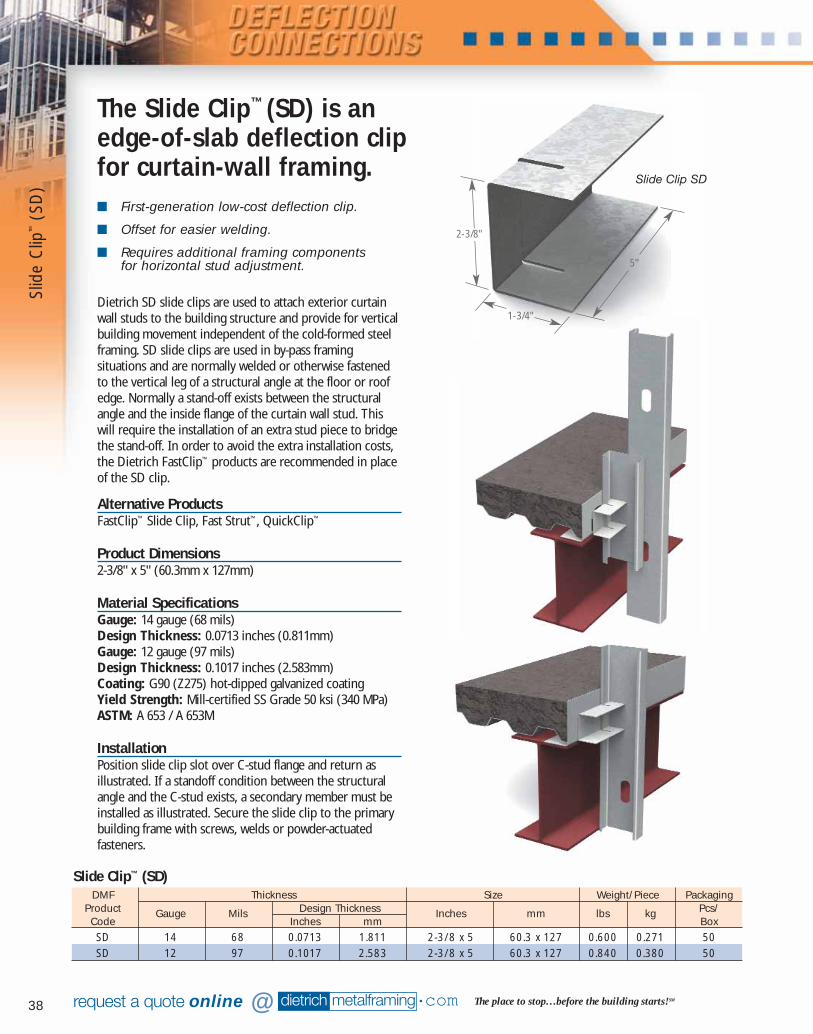
38
■ First-generation low-cost deflection clip.
■ Offset for easier welding.
■ Requires additional framing components for horizontal stud adjustment.
dietrich metalframing •com The place to stop…before the building starts! SMrequest a quote online @
Dietrich SD slide clips are used to attach exterior curtainwall studs to the building structure and provide for verticalbuilding movement independent of the cold-formed steelframing. SD slide clips are used in by-pass framingsituations and are normally welded or otherwise fastenedto the vertical leg of a structural angle at the floor or roofedge. Normally a stand-off exists between the structuralangle and the inside flange of the curtain wall stud. Thiswill require the installation of an extra stud piece to bridgethe stand-off. In order to avoid the extra installation costs,the Dietrich FastClip™ products are recommended in placeof the SD clip.
Alternative ProductsFastClip™ Slide Clip, Fast Strut™, QuickClip™
Product Dimensions2-3/8" x 5" (60.3mm x 127mm)
Material SpecificationsGauge: 14 gauge (68 mils)Design Thickness: 0.0713 inches (0.811mm)Gauge: 12 gauge (97 mils)Design Thickness: 0.1017 inches (2.583mm)Coating: G90 (Z275) hot-dipped galvanized coatingYield Strength: Mill-certified SS Grade 50 ksi (340 MPa)ASTM: A 653 / A 653M
InstallationPosition slide clip slot over C-stud flange and return asillustrated. If a standoff condition between the structuralangle and the C-stud exists, a secondary member must beinstalled as illustrated. Secure the slide clip to the primarybuilding frame with screws, welds or powder-actuatedfasteners.
The Slide Clip™ (SD) is anedge-of-slab deflection clipfor curtain-wall framing.
Slide Clip SD
DMF Thickness Size Weight/Piece PackagingProduct Gauge Mils Design Thickness Inches mm lbs kg Pcs/Code Inches mm BoxSD 14 68 0.0713 1.811 2-3/8 x 5 60.3 x 127 0.600 0.271 50SD 12 97 0.1017 2.583 2-3/8 x 5 60.3 x 127 0.840 0.380 50
Slide Clip™ (SD)
5"
2-3/8"
1-3/4"
Slid
e C
lip™
(SD
)
081016 DMF Catalog 18-39.qxd:Pgs 18-39 6/24/10 3:32 PM Page 38

39Available for Overnight Delivery, call 866-638-1908
Curtain Wall/Bypass
Mechanically Fastened Partially Welded
Table Notes
1) A fully welded clip is a clip that is welded across the top flange, bottom flange and side.2) A partially welded clip is a clip that is welded across the top and side only.3) A mechanically fastened slide clip requires (2) fasteners as shown in the detail.4) A 1/3 stress increase has not been used for the tabulated clip capacity for mechanical fasteners.
Allowable Clip Capacity Using Mechanical Fasteners (lb)Stud
Min StudAllowable Welded
Using Hilti 0.145 dia. X-DNS Pins with 15 mm dia. Washers BuildexType/ Stud
Thickness FyClip Capacity (lb)
12-24, Flange Gauge
(Inches) (ksi)Using a Safety Factor of 5 Using a Safety Factor of 10
T5 TEK Width Fully Partially Steel Thickness (Inches)
ScrewsWelded Welded 3/16" 1/4" 3/8" 1/2" 3/16" 1/4" 3/8" 1/2"
20 0.0329 33 880 440 270 378 378 378 135 191 251 281 51518 0.0428 33 880 440 270 378 378 378 135 191 251 281 515
16 0.053833 880 440 270 378 378 378 135 191 251 281 515
CWN=1.375"50 880 440 270 378 378 378 135 191 251 281 515
14 0.067733 880 440 270 378 378 378 135 191 251 281 51550 880 440 270 378 378 378 135 191 251 281 515
12 0.096633 880 440 270 378 378 378 135 191 251 281 51550 880 440 270 378 378 378 135 191 251 281 515
20 0.0329 33 380 380 270 378 378 378 135 191 251 281 38018 0.0428 33 402 402 270 378 378 378 135 191 251 281 402
16 0.053833 635 440 270 378 378 378 135 191 251 281 515
CSJ=1.625"50 880 440 270 378 378 378 135 191 251 281 515
14 0.067733 880 440 270 378 378 378 135 191 251 281 51550 880 440 270 378 378 378 135 191 251 281 515
12 0.096633 880 440 270 378 378 378 135 191 251 281 51550 880 440 270 378 378 378 135 191 251 281 515
20 0.0329 33 173 173 173 173 173 173 135 173 173 173 17318 0.0428 33 183 183 183 183 183 183 135 183 183 183 183
16 0.053833 289 289 270 289 289 289 135 191 251 281 289
CSW=2"50 437 437 270 378 378 378 135 191 251 281 437
14 0.067733 457 440 270 378 378 378 135 191 251 281 45750 693 440 270 378 378 378 135 191 251 281 515
12 0.096633 880 440 270 378 378 378 135 191 251 281 51550 880 440 270 378 378 378 135 191 251 281 515
20 0.0329 33 100 100 100 100 100 100 100 100 100 100 10018 0.0428 33 106 106 106 106 106 106 106 106 106 106 106
16 0.053833 167 167 167 167 167 167 135 167 167 167 167
CSE=2.5"50 253 253 253 253 253 253 135 191 251 253 253
14 0.067733 265 265 265 265 265 265 135 191 251 265 26550 401 401 270 378 378 378 135 191 251 281 401
12 0.096633 539 440 270 378 378 378 135 191 251 281 51550 816 440 270 378 378 378 135 191 251 281 515
20 0.0329 33 70 70 70 70 70 70 70 70 70 70 7018 0.0428 33 74 74 74 74 74 74 74 74 74 74 74
16 0.053833 118 118 118 118 118 118 118 118 118 118 118
CSS=3"50 178 178 178 178 178 178 135 178 178 178 178
14 0.067733 186 186 186 186 186 186 135 186 186 186 18650 282 282 270 282 282 282 135 191 251 281 282
12 0.096633 379 379 270 378 378 378 135 191 251 281 37950 574 440 270 378 378 378 135 191 251 281 515
* 14 gauge Slide Clip™ (SD) data available on request.
Slide Clip (SD) Allowable Loads for Dietrich 12 Gauge, 50 ksi Slide Clips
3/8"3/8"
Fully Welded
1"t 1"t
1"t 1"t
1"t
Slide Clip
™(SD
)
081016 DMF Catalog 18-39.qxd:Pgs 18-39 6/24/10 3:32 PM Page 39

1
2
3
413
15
14
12
10
11
9
5
6
7
8
40*For demonstration purposes only. Simpson® Holdownshould be installed where strapping and gusset connect.
07856 DMF Catalog 40-81.qxd:Pgs 40-81 6/24/10 3:26 PM Page 40

6 EasyClip™
X-Series™
Clip Anglespages 54-55
7 EasyClip™
A-Series™
End Clips pages 56-57
8 EasyClip™
D-Series™
AnchorClippages 58-59
9 EasyClip™
T-Series™
Anchor Clippages 58-59
10 Simpson®
Holdownspages 60-61
11 Simpson®
Tension Ties pages 62-63
12 Gusset Platespages 64-65
13 H-Series™
Universal Header Hanger pages 66-67
14 HDS®
FramingSystempages 68-81
2 EasyClip™
E-Series™
Support Clipspages 44-47
3 EasyClip™
S-Series™
Support Clipspages 48-49
5 EasyClip™
B-Series™
Clip Angles pages 52-53
4 EasyClip™
U-Series™
Clip Anglespages 50-51
41
1 Uni-Clip™
pages 42-43
15 HDSC HeaderHanger Clippages 68-81
07856 DMF Catalog 40-81.qxd:Pgs 40-81 6/24/10 3:26 PM Page 41
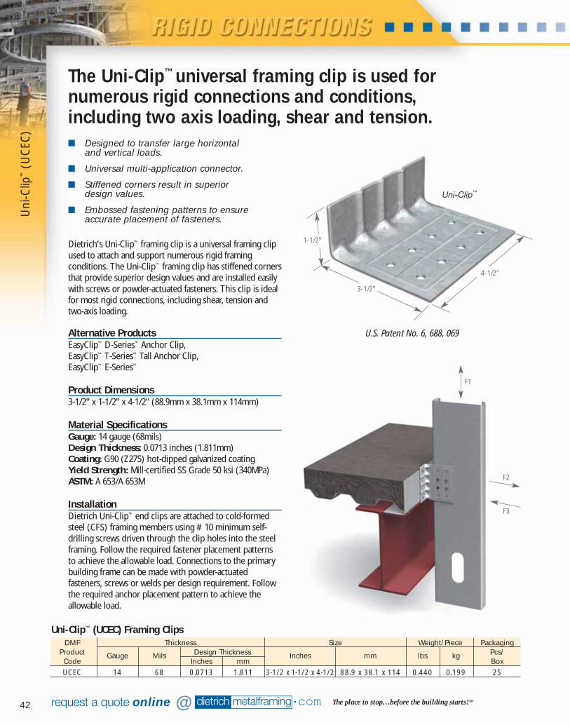
42
Uni
-Clip
™(U
CEC
)
dietrich metalframing •com The place to stop…before the building starts! SMrequest a quote online @
■ Designed to transfer large horizontal and vertical loads.
■ Universal multi-application connector.
■ Stiffened corners result in superior design values.
■ Embossed fastening patterns to ensureaccurate placement of fasteners.
Dietrich’s Uni-Clip™ framing clip is a universal framing clipused to attach and support numerous rigid framingconditions. The Uni-Clip™ framing clip has stiffened cornersthat provide superior design values and are installed easilywith screws or powder-actuated fasteners. This clip is idealfor most rigid connections, including shear, tension andtwo-axis loading.
Alternative ProductsEasyClip™ D-Series™ Anchor Clip, EasyClip™ T-Series™ Tall Anchor Clip, EasyClip™ E-Series™
Product Dimensions3-1/2" x 1-1/2" x 4-1/2" (88.9mm x 38.1mm x 114mm)
Material SpecificationsGauge: 14 gauge (68mils)Design Thickness: 0.0713 inches (1.811mm)Coating: G90 (Z275) hot-dipped galvanized coatingYield Strength: Mill-certified SS Grade 50 ksi (340MPa)ASTM: A 653/A 653M
InstallationDietrich Uni-Clip™ end clips are attached to cold-formedsteel (CFS) framing members using #10 minimum self-drilling screws driven through the clip holes into the steelframing. Follow the required fastener placement patternsto achieve the allowable load. Connections to the primarybuilding frame can be made with powder-actuatedfasteners, screws or welds per design requirement. Followthe required anchor placement pattern to achieve theallowable load.
DMF Thickness Size Weight/Piece PackagingProduct Gauge Mils Design Thickness Inches mm lbs kg Pcs/Code Inches mm BoxUCEC 14 68 0.0713 1.811 3-1/2 x 1-1/2 x 4-1/2 88.9 x 38.1 x 114 0.440 0.199 25
Uni-Clip™ (UCEC) Framing Clips
Uni-Clip™
The Uni-Clip™ universal framing clip is used fornumerous rigid connections and conditions,including two axis loading, shear and tension.
3-1/2"
1-1/2"
4-1/2"
U.S. Patent No. 6, 688, 069
F3
F2
F1
07856 DMF Catalog 40-81.qxd:Pgs 40-81 6/24/10 3:26 PM Page 42
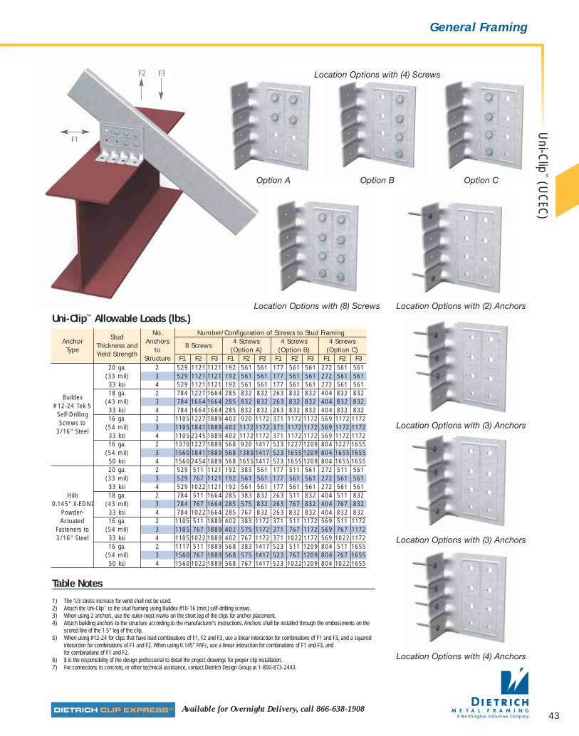
43Available for Overnight Delivery, call 866-638-1908
Uni-C
lip™
(UC
EC)
General Framing
Table Notes
1) The 1/3 stress increase for wind shall not be used.2) Attach the Uni-Clip™ to the stud framing using Buildex #10-16 (min.) self-drilling screws.3) When using 2 anchors, use the outer-most marks on the short leg of the clips for anchor placement.4) Attach building anchors to the structure according to the manufacturer's instructions. Anchors shall be installed through the embossments on the
scored line of the 1.5" leg of the clip.5) When using #12-24 for clips that have load combinations of F1, F2 and F3, use a linear interaction for combinations of F1 and F3, and a squared
interaction for combinations of F1 and F2. When using 0.145" PAFs, use a linear interaction for combinations of F1 and F3, and for combinations of F1 and F2.
6) It is the responsibility of the design professional to detail the project drawings for proper clip installation.7) For connections to concrete, or other technical assistance, contact Dietrich Design Group at 1-800-873-2443.
Location Options with (4) Screws
Option A Option B Option C
Location Options with (2) AnchorsLocation Options with (8) Screws
Location Options with (4) Anchors
StudNo. Number/Configuration of Screws to Stud Framing
AnchorThickness and
Anchors8 Screws
4 Screws 4 Screws 4 Screws Type
Yield Strengthto (Option A) (Option B) (Option C)
Structure F1 F2 F3 F1 F2 F3 F1 F2 F3 F1 F2 F320 ga. 2 529 1121 1121 192 561 561 177 561 561 272 561 561
(33 mil) 3 529 1121 1121 192 561 561 177 561 561 272 561 56133 ksi 4 529 1121 1121 192 561 561 177 561 561 272 561 561
Buildex18 ga. 2 784 1227 1664 285 832 832 263 832 832 404 832 832
#12-24 Tek 5 (43 mil) 3 784 16641664 285 832 832 263 832 832 404 832 832
Self-Drilling 33 ksi 4 784 16641664 285 832 832 263 832 832 404 832 832
Screws to 16 ga. 2 1105 1227 1889 402 920 1172 371 1172 1172 569 1172 1172
3/16" Steel(54 mil) 3 1105 1841 1889 402 1172 1172 371 1172 1172 569 1172 117233 ksi 4 110523451889 402 1172 1172 371 1172 1172 569 1172 117216 ga. 2 1370 1227 1889 568 920 1417 523 12271209 804 1227 1655
(54 mil) 3 15601841 1889 568 1380 1417 523 16551209 804 1655 165550 ksi 4 156024541889 568 1655 1417 523 16551209 804 1655 165520 ga. 2 529 511 1121 192 383 561 177 511 561 272 511 561
(33 mil) 3 529 767 1121 192 561 561 177 561 561 272 561 56133 ksi 4 529 1022 1121 192 561 561 177 561 561 272 561 561
Hilti 18 ga. 2 784 511 1664 285 383 832 263 511 832 404 511 8320.145" X-EDNI (43 mil) 3 784 767 1664 285 575 832 263 767 832 404 767 832
Powder- 33 ksi 4 784 1022 1664 285 767 832 263 832 832 404 832 832Actuated 16 ga. 2 1105 511 1889 402 383 1172 371 511 1172 569 511 1172
Fasteners to (54 mil) 3 1105 767 1889 402 575 1172 371 767 1172 569 767 11723/16" Steel 33 ksi 4 11051022 1889 402 767 1172 371 1022 1172 569 1022 1172
16 ga. 2 1117 511 1889 568 383 1417 523 511 1209 804 511 1655(54 mil) 3 1560 767 1889 568 575 1417 523 767 1209 804 767 165550 ksi 4 15601022 1889 568 767 1417 523 10221209 804 1022 1655
Uni-Clip™ Allowable Loads (lbs.)
Location Options with (3) Anchors
Location Options with (3) Anchors
F1
F3F2
07856 DMF Catalog 40-81.qxd:Pgs 40-81 6/24/10 3:26 PM Page 43
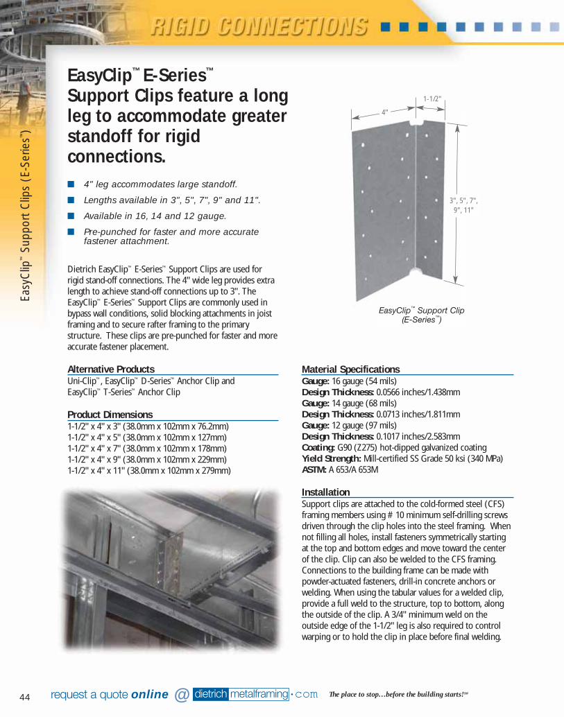
44
Easy
Clip
™Su
ppor
t Clip
s (E
-Ser
ies™
)
dietrich metalframing •com The place to stop…before the building starts! SMrequest a quote online @
■ 4" leg accommodates large standoff.
■ Lengths available in 3", 5", 7", 9" and 11".
■ Available in 16, 14 and 12 gauge.
■ Pre-punched for faster and more accuratefastener attachment.
Material SpecificationsGauge: 16 gauge (54 mils)Design Thickness: 0.0566 inches/1.438mmGauge: 14 gauge (68 mils)Design Thickness: 0.0713 inches/1.811mmGauge: 12 gauge (97 mils)Design Thickness: 0.1017 inches/2.583mmCoating: G90 (Z275) hot-dipped galvanized coatingYield Strength: Mill-certified SS Grade 50 ksi (340 MPa)ASTM: A 653/A 653M
InstallationSupport clips are attached to the cold-formed steel (CFS)framing members using #10 minimum self-drilling screwsdriven through the clip holes into the steel framing. Whennot filling all holes, install fasteners symmetrically startingat the top and bottom edges and move toward the centerof the clip. Clip can also be welded to the CFS framing.Connections to the building frame can be made withpowder-actuated fasteners, drill-in concrete anchors orwelding. When using the tabular values for a welded clip,provide a full weld to the structure, top to bottom, alongthe outside of the clip. A 3/4" minimum weld on theoutside edge of the 1-1/2" leg is also required to controlwarping or to hold the clip in place before final welding.
EasyClip™ E-Series™
Support Clips feature a longleg to accommodate greaterstandoff for rigidconnections.
EasyClip™ Support Clip(E-Series™)
3", 5", 7",9", 11"
4"
1-1/2"
Dietrich EasyClip™ E-Series™ Support Clips are used forrigid stand-off connections. The 4" wide leg provides extralength to achieve stand-off connections up to 3". TheEasyClip™ E-Series™ Support Clips are commonly used inbypass wall conditions, solid blocking attachments in joistframing and to secure rafter framing to the primarystructure. These clips are pre-punched for faster and moreaccurate fastener placement.
Alternative ProductsUni-Clip™, EasyClip™ D-Series™ Anchor Clip and EasyClip™ T-Series™ Anchor Clip
Product Dimensions1-1/2" x 4" x 3" (38.0mm x 102mm x 76.2mm)1-1/2" x 4" x 5" (38.0mm x 102mm x 127mm)1-1/2" x 4" x 7" (38.0mm x 102mm x 178mm)1-1/2" x 4" x 9" (38.0mm x 102mm x 229mm)1-1/2" x 4" x 11" (38.0mm x 102mm x 279mm)
07856 DMF Catalog 40-81.qxd:Pgs 40-81 6/24/10 3:26 PM Page 44
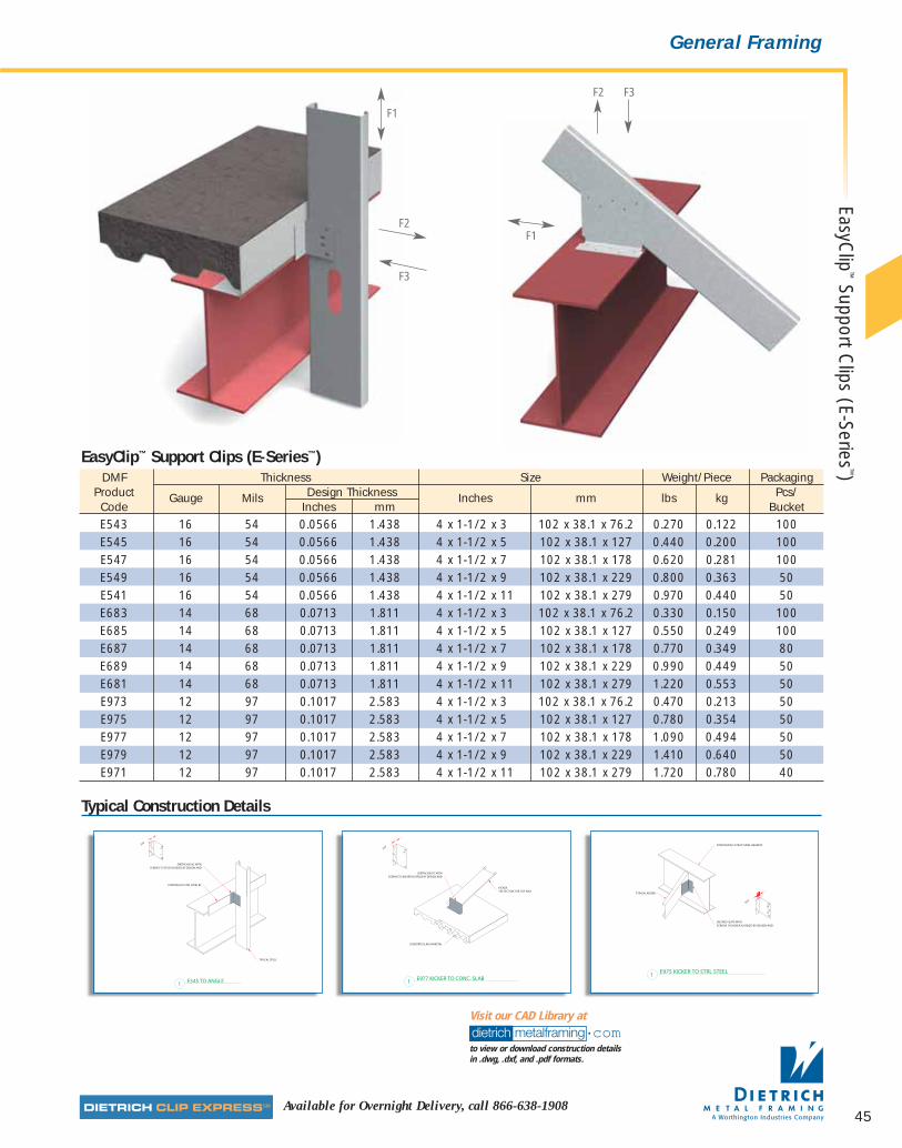
45Available for Overnight Delivery, call 866-638-1908
EasyClip
™Support C
lips (E-Series™)
General Framing
Typical Construction Details
DMF Thickness Size Weight/Piece PackagingProduct Gauge Mils Design Thickness Inches mm lbs kg Pcs/Code Inches mm BucketE543 16 54 0.0566 1.438 4 x 1-1/2 x 3 102 x 38.1 x 76.2 0.270 0.122 100E545 16 54 0.0566 1.438 4 x 1-1/2 x 5 102 x 38.1 x 127 0.440 0.200 100E547 16 54 0.0566 1.438 4 x 1-1/2 x 7 102 x 38.1 x 178 0.620 0.281 100E549 16 54 0.0566 1.438 4 x 1-1/2 x 9 102 x 38.1 x 229 0.800 0.363 50E541 16 54 0.0566 1.438 4 x 1-1/2 x 11 102 x 38.1 x 279 0.970 0.440 50E683 14 68 0.0713 1.811 4 x 1-1/2 x 3 102 x 38.1 x 76.2 0.330 0.150 100E685 14 68 0.0713 1.811 4 x 1-1/2 x 5 102 x 38.1 x 127 0.550 0.249 100E687 14 68 0.0713 1.811 4 x 1-1/2 x 7 102 x 38.1 x 178 0.770 0.349 80E689 14 68 0.0713 1.811 4 x 1-1/2 x 9 102 x 38.1 x 229 0.990 0.449 50E681 14 68 0.0713 1.811 4 x 1-1/2 x 11 102 x 38.1 x 279 1.220 0.553 50E973 12 97 0.1017 2.583 4 x 1-1/2 x 3 102 x 38.1 x 76.2 0.470 0.213 50E975 12 97 0.1017 2.583 4 x 1-1/2 x 5 102 x 38.1 x 127 0.780 0.354 50E977 12 97 0.1017 2.583 4 x 1-1/2 x 7 102 x 38.1 x 178 1.090 0.494 50E979 12 97 0.1017 2.583 4 x 1-1/2 x 9 102 x 38.1 x 229 1.410 0.640 50E971 12 97 0.1017 2.583 4 x 1-1/2 x 11 102 x 38.1 x 279 1.720 0.780 40
EasyClip™ Support Clips (E-Series™)
dietrich metalframing •comto view or download construction details in .dwg, .dxf, and .pdf formats.
Visit our CAD Library at
F3
F2
F1
F1
F3F2
07856 DMF Catalog 40-81.qxd:Pgs 40-81 6/24/10 3:26 PM Page 45
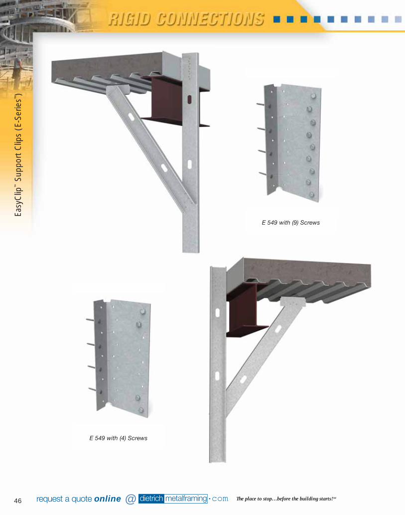
46
Easy
Clip
™Su
ppor
t Clip
s (E
-Ser
ies™
)
dietrich metalframing •com The place to stop…before the building starts! SMrequest a quote online @
E 549 with (9) Screws
E 549 with (4) Screws
07856 DMF Catalog 40-81.qxd:Pgs 40-81 6/24/10 3:26 PM Page 46

47Available for Overnight Delivery, call 866-638-1908
EasyClip
™Support C
lips (E-Series™)
General Framing
Table Notes
Screw Capacity Notes:1) The tabulated value indicates the number of screws in a single clip leg attached to the cold-
formed steel (CFS) framing.2) Screws shall be attached in a symmetric manner, starting at the outside holes.
See screw options on opposite page for examples.3) The allowable values for F1 are based only on the shear capacity of the 4" clip leg attached to
the CFS framing. The capacity of the attachment to other materials and structures must bechecked separately.
4) The allowable values for F2 assume mechanical fasteners are attached to the structure usingthe 1.5" leg, and are along the vertical centerline of the clip leg. Mechanical fasteners to othermaterials and structures must be checked separately.
5) This table is intended for use by qualified engineers only. It is the responsibility of the engineerto verify that the tabulated values apply to a specific connection application.
6) When clips have combinations of F1, F2, and F3, use a linear interaction for combinations ofF1 and F3, and a squared interaction for combinations of F1 and F2.
7) The screw diameter must be 0.19" (min.) for #10 screws.
8) The ultimate screw shear strength must be a minimum of 1400 lbs. for #10 screws.9) Screws must be long enough so that at least 3 exposed threads are visible after installation.10) Screw capacity is based on the 1996 AISI Specification.11) Allowable loads have not been increased 33% for wind or seismic.12) For connections made to 14 ga. (68 mils.) and 12 ga. (97 mils.), use the tabulated values
for 16 ga. (54 mils.), 50 ksi.13) Contact Dietrich Design Group at 1-800-873-2443 for technical assistance.Weld Capacity Notes:1) F1 and F2 values in parentheses are maximum shear and tension capacities when the clips
are welded to the base structure (min 3/16" — 36 ksi)2) Listed weld capacities are computed assuming a E60XX welding rod or wire.3) The clips are to be welded to the structure along the back corner along
the complete length of the clip. When secondary welds are used to hold the clip in place, they are not used in capacity calculations.
No. of Stud Thickness and Yield Strength
ClipScrews to 20 gauge (33 mil) 18 gauge (43 mil) 16 gauge (54mil )
Steel 33 ksi 33 ksi 50 ksiFraming (1) F1 F2 F3 F1 F2 F3 F1 F2 F3
E543 3 101(101) 210(531) 507 150(150) 210(788) 507 266(155) 210(1195) 507
E545 2 176(176) 354(354) 354 261(261) 371(525) 525 463(453) 371(933) 8115 251(251) 371(885) 885 372(372) 371(1313) 912 625(479) 371(2105) 912
E547 4 380(380) 531(708) 708 564(564) 531(1050) 1050 1002(970) 531(1867) 13477 455(455) 531(1239) 1239 675(675) 531(1838) 1318 1169(960) 531(3015) 1318
E549 4 477(477) 692(708) 708 707(707) 692(1050) 1050 1257(1257) 692(1867) 17539 706(706) 692(1593) 1593 1048(1048) 692(2363) 1724 1862(1576) 692(3925) 1724
E541 6 727(727) 852(1062) 1062 1079(1079) 852(1576) 1576 1918(1918) 852(2800) 205311 995(995) 852(1947) 1947 1476(1476) 852(2889) 2130 2623(2301) 852(4835) 2130
E683 3 101(101) 333(531) 531 150(150) 333(788) 788 266(196) 333(1400) 1011
E685 2 176(176) 354(354) 354 261(261) 525(525) 525 463(463) 587(933) 9335 251(251) 587(885) 885 372(372) 587(1313) 1313 661(602) 587(2333) 1817
E687 4 380(380) 708(708) 708 564(564) 841(1050) 1050 1002(1002) 841(1867) 18677 455(455) 841(1239) 1239 675(675) 841(1838) 1838 1200(1200) 841(3267) 2625
E689 4 477(477) 708(708) 708 707(707) 1050(1050) 1050 1257(1257) 1095(1867) 18679 706(706) 1095(1593) 1593 1048(1048) 1095(2363) 2363 1862(1862) 1095(4200) 3434
E681 6 727(727) 1062(1062) 1062 1079(1079) 1349(1576) 1576 1918(1918) 1349(2800) 280011 995(995) 1349(1947) 1947 1476(1476) 1349(2889) 2889 2623(2623) 1349(5133) 4244
E973 3 101(101) 531(531) 531 150(150) 679(788) 788 266(266) 679(1400) 1400
E975 2 176(176) 354(354) 354 261(261) 525(525) 525 463(463) 933(933) 9335 251(251) 885(885) 885 372(372) 1196(1313) 1313 661(661) 1196(2333) 2333
E977 4 380(380) 708(708) 708 564(564) 1050(1050) 1050 1002(1002) 1713(1867) 18677 455(455) 1239(1239) 1239 675(675) 1713(1838) 1838 1200(1200) 1713(3267) 3267
E979 4 477(477) 708(708) 708 707(707) 1050(1050) 1050 1257(1257) 1867(1867) 18679 706(706) 1593(1593) 1593 1048(1048) 2229(2363) 2363 1862(1862) 2229(4200) 4200
E971 6 727(727) 1062(1062) 1062 1079(1079) 1576(1576) 1576 1918(1918) 2746(2800) 280011 995(995) 1947(1947) 1947 1476(1476) 2746(2889) 2889 2623(2623) 2746(5133) 5133
E-Series™ Support Clips Allowable Clip Capacities (lbs) Using #10–16 Self-Drilling Screws
The table values are valid only whenscrews are used along the outside line
of the prepunched holes as shown.
F1
07856 DMF Catalog 40-81.qxd:Pgs 40-81 6/24/10 3:26 PM Page 47

48 dietrich metalframing •com The place to stop…before the building starts! SMrequest a quote online @
■ 1-1/2" x 1-1/2" legs.
■ Lengths available in 3", 5", 7", 9" and 11".
■ Available in 16, 14 and 12 gauge.
■ Prepunched for faster and more accuratefastener placement.
EasyClip™ S-Series™ Support Clips are used in any rigidconnection application not requiring a long leg.
EasyClip™ S-Series™ Support Clip
1-1/2"
1-1/2"
3", 5", 7", 9", 11"
F3
F2
F1
F1
F1
Dietrich EasyClip™ S-Series™ support clips are used for rigid connections in window and door framing. These clipsare also used in joist, bypass or other miscellaneousconnections to secure one framing member to another or to secure framing members to the structural frame.EasyClip™ S-Series™ clips are prepunched for faster andmore accurate fastener placement.
Alternative ProductsEasyClip™ U-Series™, EasyClip™ X-Series™, EasyClip™ D-Series™ or EasyClip™ B-Series™
Product Dimensions1-1/2" x 1-1/2" x 3" (38.1mm x 38.1mm x 76.2 mm)1-1/2" x 1-1/2" x 5" (38.1mm x 38.1mm x 127 mm)1-1/2" x 1-1/2" x 7" (38.1mm x 38.1mm x 178 mm)1-1/2" x 1-1/2" x 9" (38.1mm x 38.1mm x 229 mm)1-1/2" x 1-1/2" x 11" (38.1mm x 38.1mm x 279 mm)
Material SpecificationsGauge: 16 gauge (54 mils)Design Thickness: 0.0566 inches (1.438 mm)Gauge: 14 gauge (68 mils)Design Thickness: 0.0713 inches (1.811 mm)Gauge: 12 gauge (97 mils)Design Thickness: 0.1017 inches (2.583 mm)Coating: G90 (Z275) hot-dipped galvanized coatingYield Strength: Mill-certified SS Grade 50 ksi (340 MPa)ASTM: A 653/A 653M
InstallationE-Series™ support clips are attached to the cold-formedsteel (CFS) framing members using #10 minimum self-drilling screws driven through the clip holes into the steelframing. When not filling all holes, install fastenerssymmetrically starting at the top and bottom edges andmove toward the center of the clip. Clip can also be weldedto the CFS framing. Connections to the building frame canbe made with powder-actuated fasteners, drill-in concreteanchors or welding. When using the tabular values for awelded clip, provide a full weld to the structure, top tobottom, along the outside of the clip. A 3/4" minimum weldon the outside edge of the 1-1/2" leg is also required tocontrol warping or to hold the clip in place before finalwelding.
Easy
Clip
™S-
Serie
s™Su
ppor
t Clip
s
Figure 1
07856 DMF Catalog 40-81.qxd:Pgs 40-81 6/24/10 3:26 PM Page 48
49Available for Overnight Delivery, call 866-638-1908
General Framing
Table NotesScrew Capacity Notes:1) The tabulated value indicates the number of screws in a single clip leg attached to the
cold-formed steel (CFS) framing.2) Screws shall be attached in a symmetric manner, starting at the outside holes and moving to the center.
Reference Figure 1 on opposite page3) The allowable values for F1 are based only on the shear capacity of the clip leg attached to the CFS framing.
The capacity of the attachment to other materials and structures must be checked separately.4) The allowable values for F2 assume mechanical fasteners are attached to the structure, and are along the
vertical centerline of the clip leg. Mechanical fasteners to other materials and structures must be checkedseparately.
5) The screw diameter must be 0.19" (min.) for #10 screws.6) The ultimate screw shear strength must be a minimum of 1400 lbs. for #10 screws.7) When clips have combinations of F1, F2, and F3, use a linear interaction for combinations of F1 and F3, and
a squared interaction for combinations of F1 and F2.8) Screws must be long enough so that at least 3 exposed threads are visible after installation.
9) Screw capacity is based on the 1996 AISI Specification.10) Allowable loads have not been increased 33% for wind or seismic. 11) For connections made to 14 ga. (68 mils.) and 12 ga. (97 mils.), use the tabulated values
for 16 ga. (54 mils.), 50 ksi.12) It is the responsibility of the design professional to detail the drawings for proper clip attachment.13) Contact Dietrich Design Group at 1-800-873-2443 for technical assistance.Weld Capacity Notes:1) F1 and F2 values in parentheses are maximum shear and tension capacities when the clips are welded to
the base structure (min 3/16" — 36 ksi steel)2) Listed weld capacities are computed assuming a E60XX welding rod or wire.3) The clips are to be welded to the structure along the back corner
and along the complete length of the clip. When secondarywelds are used to hold the clip in place, they are not used incapacity calculations.
No. of Stud Thickness and Yield StrengthScrews to 20 ga (33 mil) 18 ga (43 mil) 16 ga (54mil )
Clip Steel 33 ksi 33 ksi 50 ksiFraming (1) F1 F2 F3 F1 F2 F3 F1 F2 F3
S543 3 295(295) 210(531) 531 437(437) 210(788) 788 777(555) 210(1195) 1400
S545 2 317(317) 354(354) 354 470(470) 371(525) 525 835(835) 371(933) 9335 651(651) 371(885) 885 965(965) 371(1313) 1313 1716(1460) 371(2105) 2333
S547 4 653(653) 531(708) 708 969(969) 531(1050) 1050 1722(1722) 531(1867) 18677 1029(1029) 531(1239) 1239 1526(1526) 531(1838) 1838 2712(2456) 531(3015) 3267
S549 4 679(679) 692(708) 708 1007(1007) 692(1050) 1050 1790(1790) 692(1867) 18679 1408(1408) 692(1593) 1593 2090(2090) 692(2363) 2363 3714(3452) 692(3925) 4200
S541 6 1015(1015) 852(1062) 1062 1505(1505) 852(1576) 1576 2675(2675) 852(2800) 280011 1785(1785) 852(1947) 1947 2648(2648) 852(2889) 2889 4706(4432) 852(4835) 5133
S683 3 295(295) 333(531) 531 437(437) 333(788) 788 777(699) 333(1400) 1400
S685 2 317(317) 354(354) 354 470(470) 525(525) 525 835(835) 587(933) 9335 651(651) 587(885) 885 965(965) 587(1313) 1313 1716(1716) 587(2333) 2333
S687 4 653(653) 708(708) 708 969(969) 841(1050) 1050 1722(1722) 841(1867) 18677 1029(1029) 841(1239) 1239 1526(1526) 841(1838) 1838 2712(2712) 841(3267) 3267
S689 4 679(679) 708(708) 708 1007(1007) 1050(1050) 1050 1790(1790) 1095(1867) 18679 1408(1408) 1095(1593) 1593 2090(2090) 1095(2363) 2363 3714(3714) 1095(4200) 4200
S681 6 1015(1015) 1062(1062) 1062 1505(1505) 1349(1576) 1576 2675(2675) 1349(2800) 280011 1785(1785) 1349(1947) 1947 2648(2648) 1349(2889) 2889 4706(4706) 1349(5133) 5133
S973 3 295(295) 531(531) 531 437(437) 679(788) 788 777(777) 679(1400) 1400
S975 2 317(317) 354(354) 354 470(470) 525(525) 525 835(835) 933(933) 9335 651(651) 885(885) 885 965(965) 1196(1313) 1313 1716(1716) 1196(2333) 2333
S977 4 653(653) 708(708) 708 969(969) 1050(1050) 1050 1722(1722) 1713(1867) 18677 1029(1029) 1239(1239) 1239 1526(1526) 1713(1838) 1838 2712(2712) 1713(3267) 3267
S979 4 679(679) 708(708) 708 1007(1007) 1050(1050) 1050 1790(1790) 1867(1867) 18679 1408(1408) 1593(1593) 1593 2090(2090) 2229(2363) 2363 3714(3714) 2229(4200) 4200
S971 6 1015(1015) 1062(1062) 1062 1505(1505) 1576(1576) 1576 2675(2675) 2746(2800) 280011 1785(1785) 1947(1947) 1947 2648(2648) 2746(2889) 2889 4706(4706) 2746(5133) 5133
EasyClip™ S-Series™ Support Clips Allowable Clip Capacities (lbs) Using #10–16 Self-Drilling Screws
DMF Thickness Size Weight/Piece PackagingProduct Gauge Mils Design Thickness Inches mm lbs kg Pcs/Code Inches mm BucketS543 16 54 0.0566 1.438 1-1/2 x 1-1/2 x 3 38.1 x 38.1 x 76.2 0.140 0.064 400S545 16 54 0.0566 1.438 1-1/2 x 1-1/2 x 5 38.1 x 38.1 x 127 0.240 0.109 200S547 16 54 0.0566 1.438 1-1/2 x 1-1/2 x 7 38.1 x 38.1 x 178 0.340 0.154 100S549 16 54 0.0566 1.438 1-1/2 x 1-1/2 x 9 38.1 x 38.1 x 229 0.430 0.195 100S541 16 54 0.0566 1.438 1-1/2 x 1-1/2 x 11 38.1 x 38.1 x 279 0.530 0.240 100S683 14 68 0.0713 1.811 1-1/2 x 1-1/2 x 3 38.1 x 38.1 x 76.2 0.180 0.082 200S685 14 68 0.0713 1.811 1-1/2 x 1-1/2 x 5 38.1 x 38.1 x 127 0.300 0.136 200S687 14 68 0.0713 1.811 1-1/2 x 1-1/2 x 7 38.1 x 38.1 x 178 0.420 0.191 100S689 14 68 0.0713 1.811 1-1/2 x 1-1/2 x 9 38.1 x 38.1 x 229 0.540 0.245 100S681 14 68 0.0713 1.811 1-1/2 x 1-1/2 x 11 38.1 x 38.1 x 279 0.660 0.299 100S973 12 97 0.1017 2.583 1-1/2 x 1-1/2 x 3 38.1 x 38.1 x 76.2 0.260 0.118 200S975 12 97 0.1017 2.583 1-1/2 x 1-1/2 x 5 38.1 x 38.1 x 127 0.430 0.195 150S977 12 97 0.1017 2.583 1-1/2 x 1-1/2 x 7 38.1 x 38.1 x 178 0.600 0.272 100S979 12 97 0.1017 2.583 1-1/2 x 1-1/2 x 9 38.1 x 38.1 x 229 0.770 0.349 80S971 12 97 0.1017 2.583 1-1/2 x 1-1/2 x 11 38.1 x 38.1 x 279 0.940 0.426 70
EasyClip™ S-Series™ Support Clips
EasyClip
™S-Series
™Support C
lips
07856 DMF Catalog 40-81.qxd:Pgs 40-81 6/24/10 3:26 PM Page 49
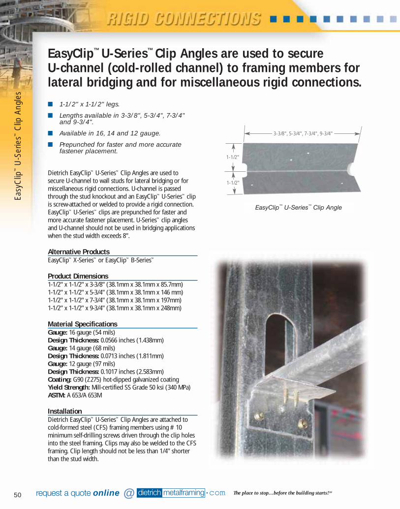
50
Easy
Clip
™U
-Ser
ies™
Clip
Ang
les
■ 1-1/2" x 1-1/2" legs.
■ Lengths available in 3-3/8", 5-3/4", 7-3/4"and 9-3/4".
■ Available in 16, 14 and 12 gauge.
■ Prepunched for faster and more accuratefastener placement.
Dietrich EasyClip™ U-Series™ Clip Angles are used to secure U-channel to wall studs for lateral bridging or formiscellaneous rigid connections. U-channel is passedthrough the stud knockout and an EasyClip™ U-Series™ clipis screw-attached or welded to provide a rigid connection.EasyClip™ U-Series™ clips are prepunched for faster andmore accurate fastener placement. U-Series™ clip anglesand U-channel should not be used in bridging applicationswhen the stud width exceeds 8".
Alternative ProductsEasyClip™ X-Series™ or EasyClip™ B-Series™
Product Dimensions1-1/2" x 1-1/2" x 3-3/8" (38.1mm x 38.1mm x 85.7mm)1-1/2" x 1-1/2" x 5-3/4" (38.1mm x 38.1mm x 146 mm)1-1/2" x 1-1/2" x 7-3/4" (38.1mm x 38.1mm x 197mm)1-1/2" x 1-1/2" x 9-3/4" (38.1mm x 38.1mm x 248mm)
Material SpecificationsGauge: 16 gauge (54 mils)Design Thickness: 0.0566 inches (1.438mm)Gauge: 14 gauge (68 mils)Design Thickness: 0.0713 inches (1.811mm)Gauge: 12 gauge (97 mils)Design Thickness: 0.1017 inches (2.583mm)Coating: G90 (Z275) hot-dipped galvanized coatingYield Strength: Mill-certified SS Grade 50 ksi (340 MPa)ASTM: A 653/A 653M
InstallationDietrich EasyClip™ U-Series™ Clip Angles are attached tocold-formed steel (CFS) framing members using #10minimum self-drilling screws driven through the clip holesinto the steel framing. Clips may also be welded to the CFSframing. Clip length should not be less than 1/4" shorterthan the stud width.
EasyClip™ U-Series™ Clip Angles are used to secure U-channel (cold-rolled channel) to framing members forlateral bridging and for miscellaneous rigid connections.
EasyClip™ U-Series™ Clip Angle
dietrich metalframing •com The place to stop…before the building starts! SMrequest a quote online @
1-1/2"
1-1/2"
3-3/8", 5-3/4", 7-3/4", 9-3/4"
07856 DMF Catalog 40-81.qxd:Pgs 40-81 6/24/10 3:26 PM Page 50
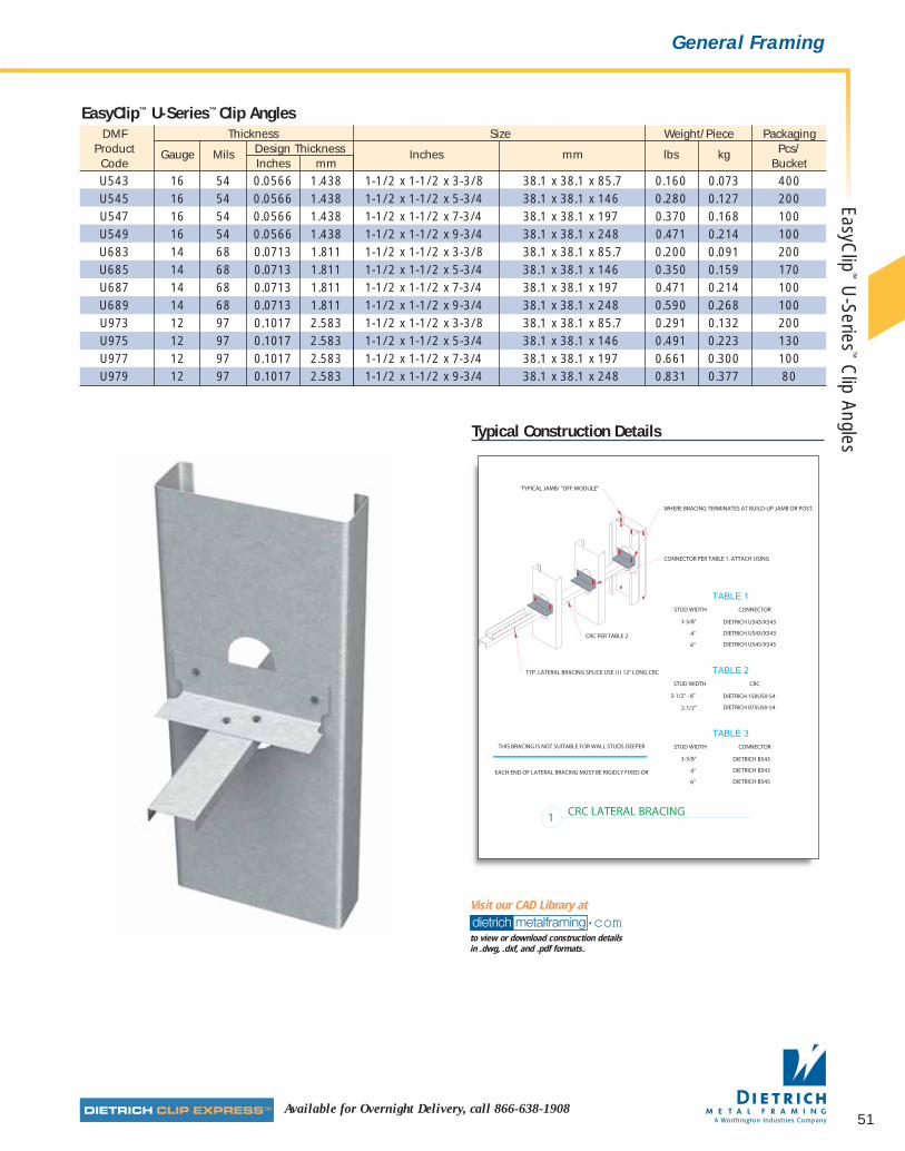
51Available for Overnight Delivery, call 866-638-1908
EasyClip
™U
-Series™
Clip Angles
General Framing
Typical Construction Details
DMF Thickness Size Weight/Piece PackagingProduct Gauge Mils Design Thickness Inches mm lbs kg Pcs/Code Inches mm BucketU543 16 54 0.0566 1.438 1-1/2 x 1-1/2 x 3-3/8 38.1 x 38.1 x 85.7 0.160 0.073 400U545 16 54 0.0566 1.438 1-1/2 x 1-1/2 x 5-3/4 38.1 x 38.1 x 146 0.280 0.127 200U547 16 54 0.0566 1.438 1-1/2 x 1-1/2 x 7-3/4 38.1 x 38.1 x 197 0.370 0.168 100U549 16 54 0.0566 1.438 1-1/2 x 1-1/2 x 9-3/4 38.1 x 38.1 x 248 0.471 0.214 100U683 14 68 0.0713 1.811 1-1/2 x 1-1/2 x 3-3/8 38.1 x 38.1 x 85.7 0.200 0.091 200U685 14 68 0.0713 1.811 1-1/2 x 1-1/2 x 5-3/4 38.1 x 38.1 x 146 0.350 0.159 170U687 14 68 0.0713 1.811 1-1/2 x 1-1/2 x 7-3/4 38.1 x 38.1 x 197 0.471 0.214 100U689 14 68 0.0713 1.811 1-1/2 x 1-1/2 x 9-3/4 38.1 x 38.1 x 248 0.590 0.268 100U973 12 97 0.1017 2.583 1-1/2 x 1-1/2 x 3-3/8 38.1 x 38.1 x 85.7 0.291 0.132 200U975 12 97 0.1017 2.583 1-1/2 x 1-1/2 x 5-3/4 38.1 x 38.1 x 146 0.491 0.223 130U977 12 97 0.1017 2.583 1-1/2 x 1-1/2 x 7-3/4 38.1 x 38.1 x 197 0.661 0.300 100U979 12 97 0.1017 2.583 1-1/2 x 1-1/2 x 9-3/4 38.1 x 38.1 x 248 0.831 0.377 80
EasyClip™ U-Series™ Clip Angles
dietrich metalframing •comto view or download construction details in .dwg, .dxf, and .pdf formats.
Visit our CAD Library at
07856 DMF Catalog 40-81.qxd:Pgs 40-81 6/24/10 3:26 PM Page 51
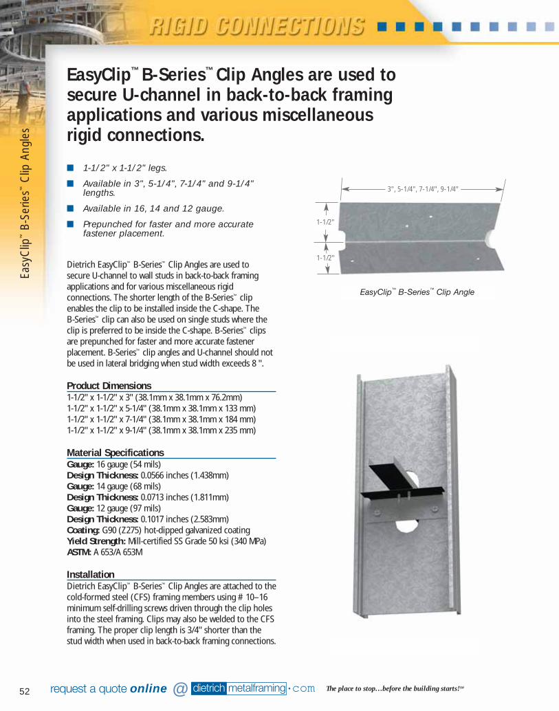
52 dietrich metalframing •com The place to stop…before the building starts! SMrequest a quote online @
■ 1-1/2" x 1-1/2" legs.
■ Available in 3", 5-1/4", 7-1/4" and 9-1/4"lengths.
■ Available in 16, 14 and 12 gauge.
■ Prepunched for faster and more accuratefastener placement.
Dietrich EasyClip™ B-Series™ Clip Angles are used to secure U-channel to wall studs in back-to-back framingapplications and for various miscellaneous rigidconnections. The shorter length of the B-Series™ clipenables the clip to be installed inside the C-shape. The B-Series™ clip can also be used on single studs where theclip is preferred to be inside the C-shape. B-Series™ clipsare prepunched for faster and more accurate fastenerplacement. B-Series™ clip angles and U-channel should notbe used in lateral bridging when stud width exceeds 8 ".
Product Dimensions1-1/2" x 1-1/2" x 3" (38.1mm x 38.1mm x 76.2mm)1-1/2" x 1-1/2" x 5-1/4" (38.1mm x 38.1mm x 133 mm)1-1/2" x 1-1/2" x 7-1/4" (38.1mm x 38.1mm x 184 mm)1-1/2" x 1-1/2" x 9-1/4" (38.1mm x 38.1mm x 235 mm)
Material SpecificationsGauge: 16 gauge (54 mils)Design Thickness: 0.0566 inches (1.438mm)Gauge: 14 gauge (68 mils)Design Thickness: 0.0713 inches (1.811mm)Gauge: 12 gauge (97 mils)Design Thickness: 0.1017 inches (2.583mm)Coating: G90 (Z275) hot-dipped galvanized coatingYield Strength: Mill-certified SS Grade 50 ksi (340 MPa)ASTM: A 653/A 653M
InstallationDietrich EasyClip™ B-Series™ Clip Angles are attached to thecold-formed steel (CFS) framing members using #10–16minimum self-drilling screws driven through the clip holesinto the steel framing. Clips may also be welded to the CFSframing. The proper clip length is 3/4" shorter than thestud width when used in back-to-back framing connections.
EasyClip™ B-Series™ Clip Angles are used tosecure U-channel in back-to-back framingapplications and various miscellaneousrigid connections.
EasyClip™ B-Series™ Clip Angle
1-1/2"
1-1/2"
3", 5-1/4", 7-1/4", 9-1/4"
Easy
Clip
™B-
Serie
s™C
lip A
ngle
s
07856 DMF Catalog 40-81.qxd:Pgs 40-81 6/24/10 3:26 PM Page 52
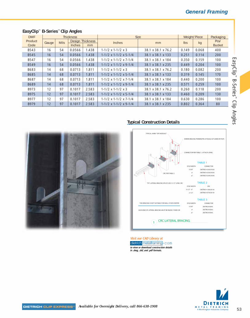
53Available for Overnight Delivery, call 866-638-1908
General Framing
Typical Construction Details
DMF Thickness Size Weight/Piece PackagingProduct Gauge Mils Design Thickness Inches mm lbs kg Pcs/Code Inches mm BucketB543 16 54 0.0566 1.438 1-1/2 x 1-1/2 x 3 38.1 x 38.1 x 76.2 0.149 0.068 400B545 16 54 0.0566 1.438 1-1/2 x 1-1/2 x 5-1/4 38.1 x 38.1 x 133 0.251 0.114 200B547 16 54 0.0566 1.438 1-1/2 x 1-1/2 x 7-1/4 38.1 x 38.1 x 184 0.350 0.159 100B549 16 54 0.0566 1.438 1-1/2 x 1-1/2 x 9-1/4 38.1 x 38.1 x 235 0.449 0.204 100B683 14 68 0.0713 1.811 1-1/2 x 1-1/2 x 3 38.1 x 38.1 x 76.2 0.180 0.082 200B685 14 68 0.0713 1.811 1-1/2 x 1-1/2 x 5-1/4 38.1 x 38.1 x 133 0.319 0.145 170B687 14 68 0.0713 1.811 1-1/2 x 1-1/2 x 7-1/4 38.1 x 38.1 x 184 0.440 0.200 100B689 14 68 0.0713 1.811 1-1/2 x 1-1/2 x 9-1/4 38.1 x 38.1 x 235 0.571 0.259 100B973 12 97 0.1017 2.583 1-1/2 x 1-1/2 x 3 38.1 x 38.1 x 76.2 0.260 0.118 200B975 12 97 0.1017 2.583 1-1/2 x 1-1/2 x 5-1/4 38.1 x 38.1 x 133 0.460 0.209 130B977 12 97 0.1017 2.583 1-1/2 x 1-1/2 x 7-1/4 38.1 x 38.1 x 184 0.630 0.286 100B979 12 97 0.1017 2.583 1-1/2 x 1-1/2 x 9-1/4 38.1 x 38.1 x 235 0.802 0.364 80
EasyClip™ B-Series™ Clip Angles
dietrich metalframing •comto view or download construction details in .dwg, .dxf, and .pdf formats.
Visit our CAD Library at
EasyClip
™B-Series
™C
lip Angles
07856 DMF Catalog 40-81.qxd:Pgs 40-81 6/24/10 3:26 PM Page 53

54 dietrich metalframing •com The place to stop…before the building starts! SMrequest a quote online @
■ 2" x 2" legs.
■ Available in 3-3/8", 5-3/4", 7-3/4" and 9-3/4"lengths.
■ Available in 16, 14 and 12 gauge.
■ Prepunched for faster and more accuratefastener placement.
Dietrich EasyClip™ X-Series™ Clip Angles are used to secureU-channel to wall studs for lateral bridging. U-Channel is passed through the stud knockout and an EasyClip™
X-Series™ clip is screw attached or welded to provide a rigidconnection. X-Series™ clip angles and U-channel should notbe used in lateral bridging when stud width exceeds 8".EasyClip™ X-Series™ clip angles are also used to secure oneframing member to another or to attach and reinforceheaders and sills in door and window openings. X-Series™
clips are prepunched for faster and more accurate fastenerplacement.
Alternative ProductsEasyClip™ U-Series™, EasyClip™ S-Series™
Product Dimensions2" x 2" x 3-3/8" (50.8mm x 50.8mm x 85.7mm)2" x 2" x 5-3/4" (50.8mm x 50.8mm x 146.0mm)2" x 2" x 7-3/4" (50.8mm x 50.8mm x 196.8mm)2" x 2" x 9-3/4" (50.8mm x 50.8mm x 247.6mm)
Material SpecificationsGauge: 16 gauge (54 mils)Design Thickness: 0.0566 inches (1.438mm)Gauge: 14 gauge (68 mils)Design Thickness: 0.0713 inches (1.811mm)Gauge: 12 gauge (97 mils)Design Thickness: 0.1017 inches (2.583mm)Coating: G90 (Z275) hot-dipped galvanized coatingYield Strength: Mill-certified SS Grade 50 ksi (340 MPa)ASTM: A 653/A 653M
EasyClip™ X-Series™ Clip Anglesare used to secure U-channel(cold-rolled channel) framingmembers for lateral bridgingor to secure one framingmember to another for rigidconnections.
InstallationEasyClip™ X-Series™ Clip Angles are attached to cold-formedsteel (CFS) framing members using #10 minimum self-drilling screws driven through the clip holes into the steelframing. Four pilot clip holes are provided and should befilled when this clip is used in a bridging application. When this clip is used in other support or connectionapplications, refer to the allowable capacity chart todetermine the appropriate number of fasteners required.As a general rule, fasteners should be evenly spaced (seefigure 1). Clips can also be welded to the CFS framing.Connections to the building frame can be made withpowder-actuated fasteners, drill-in concrete anchors orwelding. When using the tabular values for a welded clip,provide a full weld to the structure, top to bottom, alongthe outside of the clip. A 3/4" minimum weld to the outsideedge of the 2" leg is also recommended to control warpingor to hold the clip in place before final welding. When installing powder-actuated fasteners,they must be placed 1/2" minimum away from the prepunched holes.
F1
F1
F3F2
Easy
Clip
™X-
Serie
s™C
lip A
ngle
s
EasyClip™ X-Series™ Clip Angle
2"
2"
3-3/8", 5-3/4",7-3/4", 9-3/4"
Figure 1Fasteners must be evenly
spaced as noted
1" max
1/2" min
1/2" min
07856 DMF Catalog 40-81.qxd:Pgs 40-81 6/24/10 3:26 PM Page 54
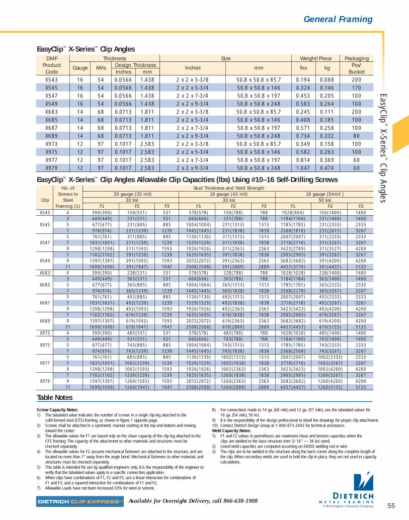
55Available for Overnight Delivery, call 866-638-1908
General Framing
DMF Thickness Size Weight/Piece PackagingProduct Gauge Mils Design Thickness Inches mm lbs kg Pcs/Code Inches mm BucketX543 16 54 0.0566 1.438 2 x 2 x 3-3/8 50.8 x 50.8 x 85.7 0.194 0.088 200X545 16 54 0.0566 1.438 2 x 2 x 5-3/4 50.8 x 50.8 x 146 0.324 0.146 170X547 16 54 0.0566 1.438 2 x 2 x 7-3/4 50.8 x 50.8 x 197 0.453 0.205 100X549 16 54 0.0566 1.438 2 x 2 x 9-3/4 50.8 x 50.8 x 248 0.583 0.264 100X683 14 68 0.0713 1.811 2 x 2 x 3-3/8 50.8 x 50.8 x 85.7 0.245 0.111 200X685 14 68 0.0713 1.811 2 x 2 x 5-3/4 50.8 x 50.8 x 146 0.408 0.185 100X687 14 68 0.0713 1.811 2 x 2 x 7-3/4 50.8 x 50.8 x 197 0.571 0.258 100X689 14 68 0.0713 1.811 2 x 2 x 9-3/4 50.8 x 50.8 x 248 0.734 0.332 80X973 12 97 0.1017 2.583 2 x 2 x 3-3/8 50.8 x 50.8 x 85.7 0.349 0.158 100X975 12 97 0.1017 2.583 2 x 2 x 5-3/4 50.8 x 50.8 x 146 0.582 0.263 100X977 12 97 0.1017 2.583 2 x 2 x 7-3/4 50.8 x 50.8 x 197 0.814 0.369 60X979 12 97 0.1017 2.583 2 x 2 x 9-3/4 50.8 x 50.8 x 248 1.047 0.474 60
EasyClip™ X-Series™ Clip Angles
No. of Stud Thickness and Yield StrengthScrews to 20 gauge (33 mil) 18 gauge (43 mil) 16 gauge (54mil )
Clip Steel 33 ksi 33 ksi 50 ksiFraming (1) F1 F2 F3 F1 F2 F3 F1 F2 F3
X543 4 390(390) 150(531) 531 578(578) 150(788) 788 1028(904) 150(1400) 14003 449(449) 231(531) 531 666(666) 231(788) 788 1184(1184) 231(1400) 1400
X545 5 677(677) 231(885) 885 1004(1004) 231(1313) 1313 1785(1785) 231(2333) 23337 974(974) 231(1239) 1239 1445(1445) 231(1838) 1838 2568(1810) 231(2617) 32675 761(761) 311(885) 885 1130(1130) 311(1313) 1313 2007(2007) 311(2333) 2333
X547 7 1031(1031) 311(1239) 1239 1529(1529) 311(1838) 1838 2718(2718) 311(3267) 32679 1298(1298) 311(1593) 1593 1926(1926) 311(2363) 2363 3423(2789) 311(3527) 42007 1102(1102) 391(1239) 1239 1635(1635) 391(1838) 1838 2905(2905) 391(3267) 3267
X549 9 1397(1397) 391(1593) 1593 2072(2072) 391(2363) 2363 3682(3682) 391(4200) 420011 1690(1690) 391(1947) 1947 2508(2508) 391(2889) 2889 4457(3779) 391(4437) 5133
X683 4 390(390) 238(531) 531 578(578) 238(788) 788 1028(1028) 238(1400) 14003 449(449) 365(531) 531 666(666) 365(788) 788 1184(1184) 365(1400) 1400
X685 5 677(677) 365(885) 885 1004(1004) 365(1313) 1313 1785(1785) 365(2333) 23337 974(974) 365(1239) 1239 1445(1445) 365(1838) 1838 2568(2278) 365(3267) 32675 761(761) 492(885) 885 1130(1130) 492(1313) 1313 2007(2007) 492(2333) 2333
X687 7 1031(1031) 492(1239) 1239 1529(1529) 492(1838) 1838 2718(2718) 492(3267) 32679 1298(1298) 492(1593) 1593 1926(1926) 492(2363) 2363 3423(3423) 492(4200) 42007 1102(1102) 619(1239) 1239 1635(1635) 619(1838) 1838 2905(2905) 619(3267) 3267
X689 9 1397(1397) 619(1593) 1593 2072(2072) 619(2363) 2363 3682(3682) 619(4200) 420011 1690(1690) 619(1947) 1947 2508(2508) 619(2889) 2889 4457(4457) 619(5133) 5133
X973 4 390(390) 485(531) 531 578(578) 485(788) 788 1028(1028) 485(1400) 14003 449(449) 531(531) 531 666(666) 743(788) 788 1184(1184) 743(1400) 1400
X975 5 677(677) 743(885) 885 1004(1004) 743(1313) 1313 1785(1785) 743(2333) 23337 974(974) 743(1239) 1239 1445(1445) 743(1838) 1838 2568(2568) 743(3267) 32675 761(761) 885(885) 885 1130(1130) 1002(1313) 1313 2007(2007) 1002(2333) 2333
X977 7 1031(1031) 1002(1239) 1239 1529(1529) 1002(1838) 1838 2718(2718) 1002(3267) 32679 1298(1298) 1002(1593) 1593 1926(1926) 1002(2363) 2363 3423(3423) 1002(4200) 42007 1102(1102) 1239(1239) 1239 1635(1635) 1260(1838) 1838 2905(2905) 1260(3267) 3267
X979 9 1397(1397) 1260(1593) 1593 2072(2072) 1260(2363) 2363 3682(3682) 1260(4200) 420011 1690(1690) 1260(1947) 1947 2508(2508) 1260(2889) 2889 4457(4457) 1260(5133) 5133
EasyClip™ X-Series™ Clip Angles Allowable Clip Capacities (lbs) Using #10–16 Self-Drilling Screws
Table Notes
Screw Capacity Notes:1) The tabulated value indicates the number of screws in a single clip leg attached to the
cold-formed steel (CFS) framing, as shown in figure 1 opposite page.2) Screws shall be attached in a symmetric manner starting at the top and bottom and moving
toward the center.3) The allowable values for F1 are based only on the shear capacity of the clip leg attached to the
CFS framing. The capacity of the attachment to other materials and structures must be checked separately.
4) The allowable values for F2 assume mechanical fasteners are attached to the structure, and arelocated no more than 1" away from the angle bend. Mechanical fasteners to other materials andstructures must be checked separately.
5) This table is intended for use by qualified engineers only. It is the responsibility of the engineer toverify that the tabulated values apply to a specific connection application.
6) When clips have combinations of F1, F2 and F3, use a linear interaction for combinations of F1 and F3, and a squared interaction for combinations of F1 and F2.
7) Allowable Loads have not been increased 33% for wind or seismic.
8) For connections made to 14 ga. (68 mils) and 12 ga. (97 mils), use the tabulated values for 16 ga. (54 mils), 50 ksi.
9) It is the responsibility of the design professional to detail the drawings for proper clip attachment.10) Contact Dietrich Design Group at 1-800-873-2443 for technical assistance.Weld Capacity Notes:1) F1 and F2 values in parentheses are maximum shear and tension capacities when the
clips are welded to the base structure (min 3/ 16" — 36 ksi steel)2) Listed weld capacities are computed assuming an E60XX welding rod or wire.3) The clips are to be welded to the structure along the back corner along the complete length of
the clip. When secondary welds are used to hold the clip in place, they are not used in capacitycalculations.
EasyClip
™X-Series
™C
lip Angles
07856 DMF Catalog 40-81.qxd:Pgs 40-81 6/24/10 3:26 PM Page 55
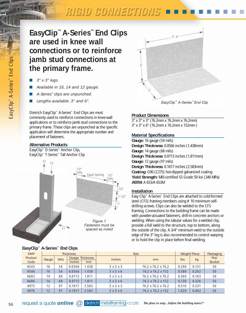
56 dietrich metalframing •com The place to stop…before the building starts! SMrequest a quote online @
■ 3" x 3" legs.
■ Available in 16, 14 and 12 gauge.
■ A-Series™ clips are unpunched.
■ Lengths available: 3" and 6".
Product Dimensions3" x 3" x 3" (76.2mm x 76.2mm x 76.2mm)3" x 3" x 6" (76.2mm x 76.2mm x 152mm )
Material SpecificationsGauge: 16 gauge (54 mils)Design Thickness: 0.0566 inches (1.438mm)Gauge: 14 gauge (68 mils)Design Thickness: 0.0713 inches (1.811mm)Gauge: 12 gauge (97 mils)Design Thickness: 0.1017 inches (2.583mm)Coating: G90 (Z275) hot-dipped galvanized coatingYield Strength: Mill-certified SS Grade 50 ksi (340 MPa)ASTM: A 653/A 653M
InstallationEasy Clip™ A-Series™ End Clips are attached to cold-formedsteel (CFS) framing members using #10 minimum self-drilling screws. Clips can also be welded to the CFSframing. Connections to the building frame can be madewith powder-actuated fasteners, drill-in concrete anchors orwelding. When using the tabular values for a welded clip,provide a full weld to the structure, top to bottom, alongthe outside of the clip. A 3/4" minimum weld to the outsideedge of the 3" leg is also recommended to control warpingor to hold the clip in place before final welding.
EasyClip™ A-Series™ End Clipsare used in knee wallconnections or to reinforcejamb stud connections at the primary frame.
EasyClip™ A-Series™ End Clip
Dietrich EasyClip™ A-Series™ End Clips are most commonly used to reinforce connections in knee-wallapplications or to reinforce jamb stud connections to theprimary frame. These clips are unpunched as the specificapplication will determine the appropriate number andplacement of fasteners.
Alternative ProductsEasyClip™ D-Series™ Anchor Clip, EasyClip™ T-Series™ Tall Anchor Clip
3", 6"
3"
3"
DMF Thickness Size Weight/Piece PackagingProduct Gauge Mils Design Thickness Inches mm lbs kg Pcs/Code Inches mm BucketA543 16 54 0.0566 1.438 3 x 3 x 3 76.2 x 76.2 x 76.2 0.290 0.131 50A546 16 54 0.0566 1.438 3 x 3 x 6 76.2 x 76.2 x 152 0.580 0.262 50A683 14 68 0.0713 1.811 3 x 3 x 3 76.2 x 76.2 x 76.2 0.360 0.163 50A686 14 68 0.0713 1.811 3 x 3 x 6 76.2 x 76.2 x 152 0.720 0.326 50A973 12 97 0.1017 2.583 3 x 3 x 3 76.2 x 76.2 x 76.2 0.510 0.231 50A976 12 97 0.1017 2.583 3 x 3 x 6 76.2 x 76.2 x 152 1.020 0.462 50
EasyClip™ A-Series™ End Clips
F1
F3F2
Easy
Clip
™A-
Serie
s™En
d C
lips
Figure 1Fasteners must bespaced as noted
Equal Spacing
1/2"
1-1/2"
1"
1/2"min
1/2"min
07856 DMF Catalog 40-81.qxd:Pgs 40-81 6/24/10 3:26 PM Page 56
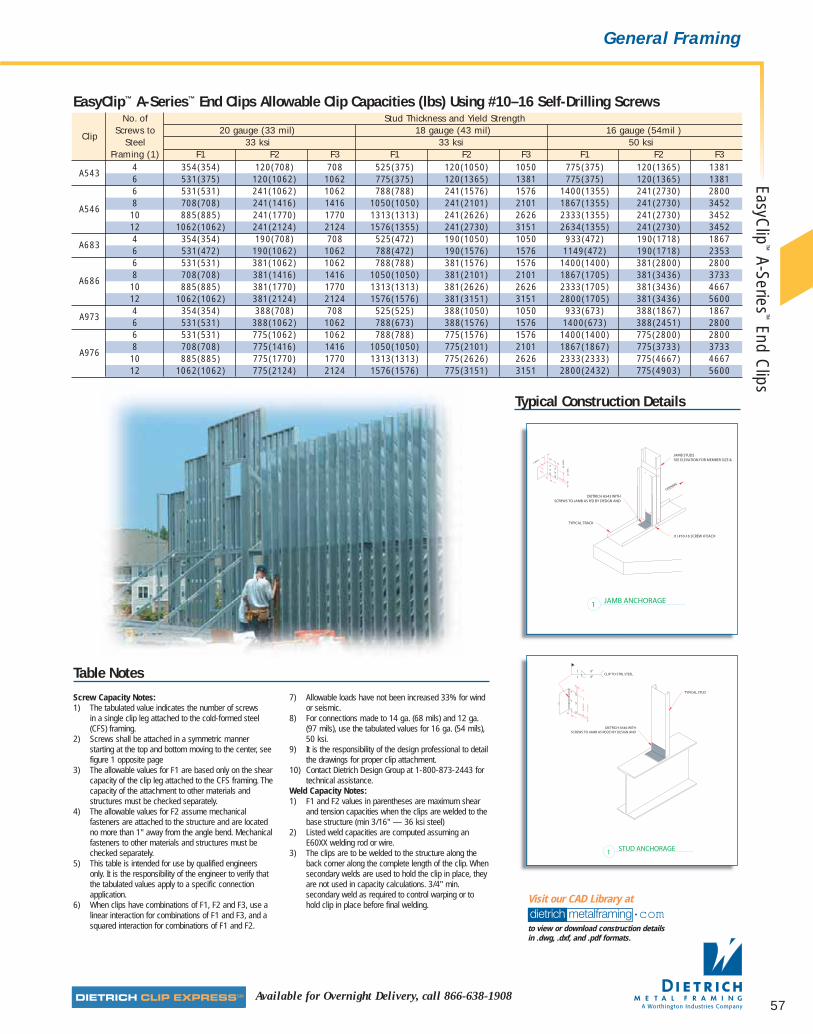
57Available for Overnight Delivery, call 866-638-1908
General Framing
No. of Stud Thickness and Yield Strength
ClipScrews to 20 gauge (33 mil) 18 gauge (43 mil) 16 gauge (54mil )
Steel 33 ksi 33 ksi 50 ksiFraming (1) F1 F2 F3 F1 F2 F3 F1 F2 F3
A5434 354(354) 120(708) 708 525(375) 120(1050) 1050 775(375) 120(1365) 13816 531(375) 120(1062) 1062 775(375) 120(1365) 1381 775(375) 120(1365) 13816 531(531) 241(1062) 1062 788(788) 241(1576) 1576 1400(1355) 241(2730) 2800
A5468 708(708) 241(1416) 1416 1050(1050) 241(2101) 2101 1867(1355) 241(2730) 345210 885(885) 241(1770) 1770 1313(1313) 241(2626) 2626 2333(1355) 241(2730) 345212 1062(1062) 241(2124) 2124 1576(1355) 241(2730) 3151 2634(1355) 241(2730) 3452
A6834 354(354) 190(708) 708 525(472) 190(1050) 1050 933(472) 190(1718) 18676 531(472) 190(1062) 1062 788(472) 190(1576) 1576 1149(472) 190(1718) 23536 531(531) 381(1062) 1062 788(788) 381(1576) 1576 1400(1400) 381(2800) 2800
A6868 708(708) 381(1416) 1416 1050(1050) 381(2101) 2101 1867(1705) 381(3436) 373310 885(885) 381(1770) 1770 1313(1313) 381(2626) 2626 2333(1705) 381(3436) 466712 1062(1062) 381(2124) 2124 1576(1576) 381(3151) 3151 2800(1705) 381(3436) 5600
A9734 354(354) 388(708) 708 525(525) 388(1050) 1050 933(673) 388(1867) 18676 531(531) 388(1062) 1062 788(673) 388(1576) 1576 1400(673) 388(2451) 28006 531(531) 775(1062) 1062 788(788) 775(1576) 1576 1400(1400) 775(2800) 2800
A9768 708(708) 775(1416) 1416 1050(1050) 775(2101) 2101 1867(1867) 775(3733) 373310 885(885) 775(1770) 1770 1313(1313) 775(2626) 2626 2333(2333) 775(4667) 466712 1062(1062) 775(2124) 2124 1576(1576) 775(3151) 3151 2800(2432) 775(4903) 5600
EasyClip™ A-Series™ End Clips Allowable Clip Capacities (lbs) Using #10–16 Self-Drilling Screws
Table Notes
Screw Capacity Notes:1) The tabulated value indicates the number of screws
in a single clip leg attached to the cold-formed steel(CFS) framing.
2) Screws shall be attached in a symmetric mannerstarting at the top and bottom moving to the center, seefigure 1 opposite page
3) The allowable values for F1 are based only on the shearcapacity of the clip leg attached to the CFS framing. Thecapacity of the attachment to other materials andstructures must be checked separately.
4) The allowable values for F2 assume mechanicalfasteners are attached to the structure and are locatedno more than 1" away from the angle bend. Mechanicalfasteners to other materials and structures must bechecked separately.
5) This table is intended for use by qualified engineersonly. It is the responsibility of the engineer to verify thatthe tabulated values apply to a specific connectionapplication.
6) When clips have combinations of F1, F2 and F3, use alinear interaction for combinations of F1 and F3, and asquared interaction for combinations of F1 and F2.
7) Allowable loads have not been increased 33% for windor seismic.
8) For connections made to 14 ga. (68 mils) and 12 ga.(97 mils), use the tabulated values for 16 ga. (54 mils),50 ksi.
9) It is the responsibility of the design professional to detailthe drawings for proper clip attachment.
10) Contact Dietrich Design Group at 1-800-873-2443 fortechnical assistance.
Weld Capacity Notes:1) F1 and F2 values in parentheses are maximum shear
and tension capacities when the clips are welded to thebase structure (min 3/16" — 36 ksi steel)
2) Listed weld capacities are computed assuming anE60XX welding rod or wire.
3) The clips are to be welded to the structure along theback corner along the complete length of the clip. Whensecondary welds are used to hold the clip in place, theyare not used in capacity calculations. 3/4" min.secondary weld as required to control warping or tohold clip in place before final welding.
Typical Construction Details
dietrich metalframing •comto view or download construction details in .dwg, .dxf, and .pdf formats.
Visit our CAD Library at
EasyClip
™A-Series
™End C
lips
07856 DMF Catalog 40-81.qxd:Pgs 40-81 6/24/10 3:26 PM Page 57

58 dietrich metalframing •com The place to stop…before the building starts! SMrequest a quote online @
■ Resist uplift, horizontal and rotational loads.
■ Stiffening ribs for superior design values.
■ Prepunched holes for fast attachment.
■ Multipurpose applications.
The Dietrich EasyClip™ D-Series™ Anchor Clips and T-Series™ Tall Anchor Clips are high-performance, cost-effective solutions for knee wall-to-foundation connections,light duty shear wall-to-foundation connections and truss-to-wall connections. These multi-application clips featurereinforced stiffening ribs that provide superior designvalues for maximum performance. The EasyClip™ D-Series™
Anchor Clips and T-Series™ Tall Anchor Clips are designedto resist horizontal, torsional and vertical (uplift) loads.These clips are prepunched with a series of attachmentholes including anchor bolt, kwik-con and screw holes, forefficient and accurate fastener placement.
Alternative ProductsEasyClip™ A-Series™ End-Clips
Product DimensionsEasyClip™ D-Series™
2" x 2" x 3-1/2" (50.8mm x 50.8mm x 88.9mm)2" x 2" x 5-1/2" (50.8mm x 50.8mm x 140.0mm)EasyClip™ T-Series™
2" x 4" x 3-1/2" (50.8mm x 101.6mm x 88.9mm)2" x 4" x 5-1/2" (50.8mm x 101.6mm x 140.0mm)
Material SpecificationsGauge: 14 gauge (68 mils)Design Thickness: 0.0713 inches (1.811mm)Gauge: 12 gauge (97 mils)Design Thickness: 0.1017 inches (2.583mm)Coating: G90 (Z275) hot-dipped galvanized coatingYield Strength: Mill-certified SS Grade 50 ksi (340 MPa)ASTM: A 653/A 653M
InstallationInstall EasyClip™ D-Series™ and T-Series™ Anchor Clips byattaching the screw hole only leg to the web of the stud,joist, rafter or track with the applicable # of fasteners(screws or welds). Secure bottom leg (anchor bolt hole) tostructure using prepunched holes provided withappropriate fastener type and # of fasteners according todesign based on load requirements.
EasyClip™ D-Series™ and T-Series™ AnchorClips provide cost-effective tie-downsolutions for knee walls, shear walls and truss connections.
DMF Thickness Size Weight/Piece PackagingProduct Gauge Mils Design Thickness Inches mm lbs kg Pcs/Code Inches mm BoxD683 14 68 0.0713 1.811 2 x 2 x 3-1/2 50.8 x 50.8 x 88.9 0.280 0.127 40T683 14 68 0.0713 1.811 2 x 4 x 3-1/2 50.8 x 101.6 x 88.9 0.421 0.191 40D685 14 68 0.0713 1.811 2 x 2 x 5-1/2 50.8 x 50.8 x 140.0 0.438 0.199 40T685 14 68 0.0713 1.811 2 x 4 x 5-1/2 50.8 x 101.6 x 140.0 0.659 0.299 40D973 12 97 0.1017 2.583 2 x 2 x 3-1/2 50.8 x 50.8 x 88.9 0.399 0.181 40T973 12 97 0.1017 2.583 2 x 4 x 3-1/2 50.8 x 101.6 x 88.9 0.599 0.272 40D975 12 97 0.1017 2.583 2 x 2 x 5-1/2 50.8 x 50.8 x 140.0 0.628 0.285 40T975 12 97 0.1017 2.583 2 x 4 x 5-1/2 50.8 x 101.6 x 140.0 0.950 0.431 40
D-Series™ Anchor Clip/T-Series™ Tall Anchor Clip
2" 2"
2" 4"
3-1/2"5-1/2"
3-1/2"5-1/2"
EasyClip™ D-Series™
Anchor Clip
EasyClip™ T-Series™
Tall Anchor Clip
Easy
Clip
™D
-Ser
ies™
Anch
or C
lip/E
asyC
lip™
T-Se
ries™
Tall
Anch
or C
lip
07856 DMF Catalog 40-81.qxd:Pgs 40-81 6/24/10 3:26 PM Page 58
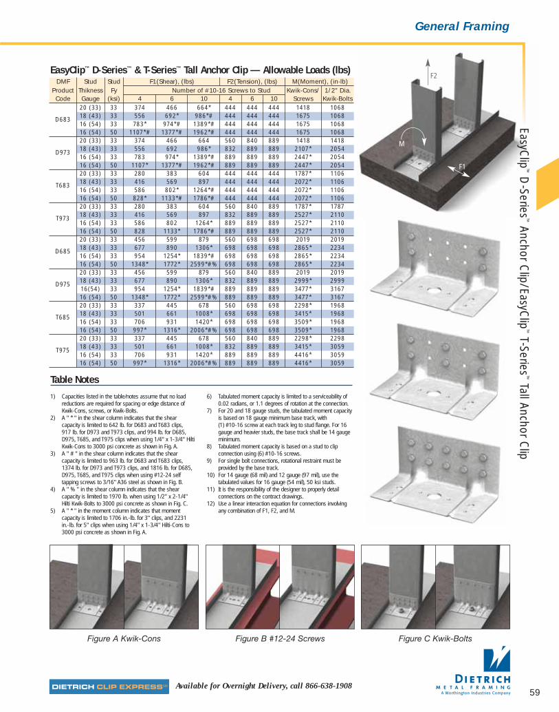
F2
F1
M
59Available for Overnight Delivery, call 866-638-1908
General FramingEasyC
lip™
D-Series
™Anchor C
lip/EasyClip
™T-Series
™Tall Anchor C
lip
DMF Stud Stud F1(Shear), (lbs) F2(Tension), (lbs) M(Moment), (in-lb)Product Thikness Fy Number of #10-16 Screws to Stud Kwik-Cons/ 1/2" Dia.Code Gauge (ksi) 4 6 10 4 6 10 Screws Kwik-Bolts
20 (33) 33 374 466 664* 444 444 444 1418 1068
D683 18 (43) 33 556 692* 986*# 444 444 444 1675 106816 (54) 33 783* 974*# 1389*# 444 444 444 1675 106816 (54) 50 1107*# 1377*# 1962*# 444 444 444 1675 106820 (33) 33 374 466 664 560 840 889 1418 1418
D973 18 (43) 33 556 692 986* 832 889 889 2107* 205416 (54) 33 783 974* 1389*# 889 889 889 2447* 205416 (54) 50 1107* 1377*# 1962*# 889 889 889 2447* 205420 (33) 33 280 383 604 444 444 444 1787* 1106
T683 18 (43) 33 416 569 897 444 444 444 2072* 110616 (54) 33 586 802* 1264*# 444 444 444 2072* 110616 (54) 50 828* 1133*# 1786*# 444 444 444 2072* 110620 (33) 33 280 383 604 560 840 889 1787* 1787
T973 18 (43) 33 416 569 897 832 889 889 2527* 211016 (54) 33 586 802 1264* 889 889 889 2527* 211016 (54) 50 828 1133* 1786*# 889 889 889 2527* 211020 (33) 33 456 599 879 560 698 698 2019 2019
D685 18 (43) 33 677 890 1306* 698 698 698 2865* 223416 (54) 33 954 1254* 1839*# 698 698 698 2865* 223416 (54) 50 1348* 1772* 2599*#% 698 698 698 2865* 223420 (33) 33 456 599 879 560 840 889 2019 2019
D975 18 (43) 33 677 890 1306* 832 889 889 2999* 299916(54) 33 954 1254* 1839*# 889 889 889 3477* 316716 (54) 50 1348* 1772* 2599*#% 889 889 889 3477* 316720 (33) 33 337 445 678 560 698 698 2298* 1968
T685 18 (43) 33 501 661 1008* 698 698 698 3415* 196816 (54) 33 706 931 1420* 698 698 698 3509* 196816 (54) 50 997* 1316* 2006*#% 698 698 698 3509* 196820 (33) 33 337 445 678 560 840 889 2298* 2298
T975 18 (43) 33 501 661 1008* 832 889 889 3415* 305916 (54) 33 706 931 1420* 889 889 889 4416* 305916 (54) 50 997* 1316* 2006*#% 889 889 889 4416* 3059
EasyClip™ D-Series™ & T-Series™ Tall Anchor Clip — Allowable Loads (lbs)
Table Notes
1) Capacities listed in the table/notes assume that no loadreductions are required for spacing or edge distance ofKwik-Cons, screws, or Kwik-Bolts.
2) A " * " in the shear column indicates that the shearcapacity is limited to 642 lb. for D683 and T683 clips, 917 lb. for D973 and T973 clips, and 994 lb. for D685,D975, T685, and T975 clips when using 1/4" x 1-3/4" HiltiKwik-Cons to 3000 psi concrete as shown in Fig. A.
3) A " # " in the shear column indicates that the shearcapacity is limited to 963 lb. for D683 and T683 clips,1374 lb. for D973 and T973 clips, and 1816 lb. for D685,D975, T685, and T975 clips when using #12-24 selftapping screws to 3/16" A36 steel as shown in Fig. B.
4) A " % " in the shear column indicates that the shearcapacity is limited to 1970 lb. when using 1/2" x 2-1/4"Hilti Kwik-Bolts to 3000 psi concrete as shown in Fig. C.
5) A " * " in the moment column indicates that momentcapacity is limited to 1706 in.-lb. for 3" clips, and 2231 in.-lb. for 5" clips when using 1/4" x 1-3/4" Hilti-Cons to3000 psi concrete as shown in Fig. A.
6) Tabulated moment capacity is limited to a serviceability of0.02 radians, or 1.1 degrees of rotation at the connection.
7) For 20 and 18 gauge studs, the tabulated moment capacityis based on 18 gauge minimum base track, with (1) #10-16 screw at each track leg to stud flange. For 16gauge and heavier studs, the base track shall be 14 gaugeminimum.
8) Tabulated moment capacity is based on a stud to clipconnection using (6) #10-16 screws.
9) For single bolt connections, rotational restraint must beprovided by the base track.
10) For 14 gauge (68 mil) and 12 gauge (97 mil), use thetabulated values for 16 gauge (54 mil), 50 ksi studs.
11) It is the responsibility of the designer to properly detailconnections on the contract drawings.
12) Use a linear interaction equation for connections involvingany combination of F1, F2, and M.
Figure A Kwik-Cons Figure B #12-24 Screws Figure C Kwik-Bolts
07856 DMF Catalog 40-81.qxd:Pgs 40-81 6/24/10 3:26 PM Page 59
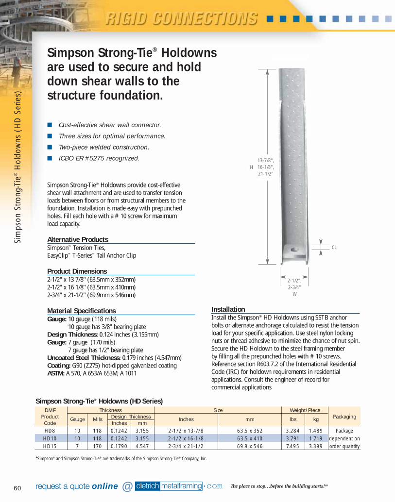
60 dietrich metalframing •com The place to stop…before the building starts! SMrequest a quote online @
■ Cost-effective shear wall connector.
■ Three sizes for optimal performance.
■ Two-piece welded construction.
■ ICBO ER #5275 recognized.
Simpson Strong-Tie® Holdowns provide cost-effective shear wall attachment and are used to transfer tensionloads between floors or from structural members to thefoundation. Installation is made easy with prepunchedholes. Fill each hole with a #10 screw for maximum load capacity.
Alternative ProductsSimpson™ Tension Ties, EasyClip™ T-Series™ Tall Anchor Clip
Product Dimensions2-1/2" x 13 7/8" (63.5mm x 352mm)2-1/2" x 16 1/8" (63.5mm x 410mm)2-3/4" x 21-1/2" (69.9mm x 546mm)
Material SpecificationsGauge: 10 gauge (118 mils)
10 gauge has 3/8" bearing plateDesign Thickness: 0.124 inches (3.155mm)Gauge: 7 gauge (170 mils)
7 gauge has 1/2" bearing plateUncoated Steel Thickness: 0.179 inches (4.547mm)Coating: G90 (Z275) hot-dipped galvanized coatingASTM: A 570, A 653/A 653M, A 1011
InstallationInstall the Simpson® HD Holdowns using SSTB anchorbolts or alternate anchorage calculated to resist the tensionload for your specific application. Use steel nylon lockingnuts or thread adhesive to minimize the chance of nut spin.Secure the HD Holdown to the steel framing member by filling all the prepunched holes with #10 screws.Reference section R603.7.2 of the International ResidentialCode (IRC) for holdown requirements in residentialapplications. Consult the engineer of record for commercial applications
Simpson Strong-Tie® Holdownsare used to secure and holddown shear walls to thestructure foundation.
DMF Thickness Size Weight/PieceProduct Gauge Mils Design Thickness Inches mm lbs kg PackagingCode Inches mmHD8 10 118 0.1242 3.155 2-1/2 x 13-7/8 63.5 x 352 3.284 1.489 PackageHD10 10 118 0.1242 3.155 2-1/2 x 16-1/8 63.5 x 410 3.791 1.719 dependent onHD15 7 170 0.1790 4.547 2-3/4 x 21-1/2 69.9 x 546 7.495 3.399 order quantity
Simpson Strong-Tie® Holdowns (HD Series)
13-7/8",16-1/8",21-1/2"
2-1/2", 2-3/4"
W
H
CL
*Simpson® and Simpson Strong-Tie® are trademarks of the Simpson Strong-Tie® Company, Inc.
Sim
pson
Stro
ng-T
ie®
Hol
dow
ns (
HD
Ser
ies)
07856 DMF Catalog 40-81.qxd:Pgs 40-81 6/24/10 3:26 PM Page 60

61Available for Overnight Delivery, call 866-638-1908
Shear Walls
Dimensions FastenersDMF
Simpson AVGAllowable Tension
Product Reference
W H CL Anchor Dia.Screws ULT
Loads
Code (lbs)(lbs)
Inches mm Inches mm Inches mm Inches mm 20 GA 18 GA 16 GAHD8 S/HD8 2-1/2 63.5 13-7/8 352 1-1/2 38.1 1/2 12.71 24- #10 29000 7615 8460 8940HD10 S/HD10 2-1/2 63.5 16-1/8 410 1-1/2 38.1 5/8 15.9 30- #10 29000 9520 9665 9665HD15 S/HD15 2-3/4 69.9 21-1/2 546 1-1/2 38.1 5/8 15.9 48- #10 46000 - 12200 13800
Simpson Strong-Tie® (HD8, HD10, HD15) Holdowns
Table Notes
1) The designer shall specify the anchorembedment and configuration. See SSTBAnchor Bolts.
2) Allowable loads have been increased33% for wind or earthquake loading withno further increase allowed.
3) Multiply the loads shown by 0.75 when a33% increase for wind or earthquakeloading is not allowed by the designstandard being used or when the 0.75load combination factor in A.I.S.I. SectionA5.1.3 (1996 Edition) is not allowed.
4) Anchor bolt washer is not required.
5) Deflection at Highest Allowable DesignLoad
6) The deflection of a holdown measuredbetween the anchor bolt and the strapportion of the holdown when loaded to thehighest allowable load listed in the catalogtable. This movement is strictly due to theholdown deformation under a static loadtest conducted on a steel jig.
7) Simpson and Simpson Strong-Tie® aretrademarks of the Simpson Strong-Tie®
Company, Inc.
Sources of Deflection at the Shearwall Holdown Connections
A) Eccentricity in stud — when a holdown isinstalled on only one side of the stud, aneccentricity exists during loading that cancause additional movement in theshearwall system
B) Nut spin — unrestrained anchor bolt nutscan spin loose during cyclic loading: theuse of steel nylon locking nuts or threadadhesive may prevent nut spin.
C) Lack of nut tightening — additionalmovement can occur when nuts are nottightened sufficiently.
D) Deflection of the holdown — deflectioncan occur in the holdown under loadcaused by stresses due to earthquake orhigh wind.
E) Vertical deflection at the holdown seatcaused by stud rotation — lateraldisplacement at the top of the wall rotatesthe stud around its base causing theholdown base plate to displace vertically.
Typical Construction Details
dietrich metalframing •comto view or download construction details in .dwg, .dxf, and .pdf formats.
Visit our CAD Library at
A
B C
D E
Simpson Strong-Tie
®H
oldowns (H
D Series)
07856 DMF Catalog 40-81.qxd:Pgs 40-81 6/24/10 3:26 PM Page 61

62 dietrich metalframing •com The place to stop…before the building starts! SMrequest a quote online @
■ Cost-effective shear wall connector.
■ Single-piece construction.
■ Post-pour installation.
■ ICBO ER #5275 recognized.
Simpson Strong-Tie® Tension Ties are designed to providean economical option for light to medium upliftrequirements. The HT14 tension tie is ideal for retrofit ornew construction. They provide high-strength, post-pour,concrete-to-steel connections.
Alternative ProductsSimpson Strong-Tie® Holdowns, EasyClip™ D-Series™
Anchor Clip or EasyClip™ T-Series™ Tall Anchor Clip
Product Dimensions2-1/2" x 15" (63.5mm x 381mm)
Material SpecificationsGauge: 11 gauge (114 mils)Uncoated Steel Thickness: 0.120 inches (3.048 mm)Coating: G90 (Z275) hot-dipped galvanized coating.ASTM: A 653/A 653M
InstallationInstall the Simpson Strong-Tie® HT14 Holdown using SSTBanchor bolts or alternate anchorage calculated to resist thetension load for your specific application. Use steel nylonlocking nuts or thread adhesive to minimize the chance ofnut spin. No washers are required. Secure the HT14Tension Tie to the steel framing member by filling all theprepunched holes with the specified number and type of screw.
Simpson Strong-Tie® Tension Ties are single-piecetension ties for shear wall anchorage for light tomedium uplift requirements.
*Simpson® and Simpson Strong-Tie® are trademarks of the Simpson Strong-Tie® Company, Inc.
DMF Thickness Size Weight/Piece PackagingProduct Gauge Mils Design Thickness Inches mm lbs kg Pcs/Code Inches mm BoxHT14 11 114 0.120 3.048 2-1/2 x 15 63.5 x 381 2.150 0.975 10
Simpson Strong-Tie® Tension Ties (HT14)
2",2-1/2"
20",15"
H
W
CL
Sim
pson
Stro
ng-T
ie®
Tens
ion
Ties
(H
T14)
07856 DMF Catalog 40-81.qxd:Pgs 40-81 6/24/10 3:27 PM Page 62
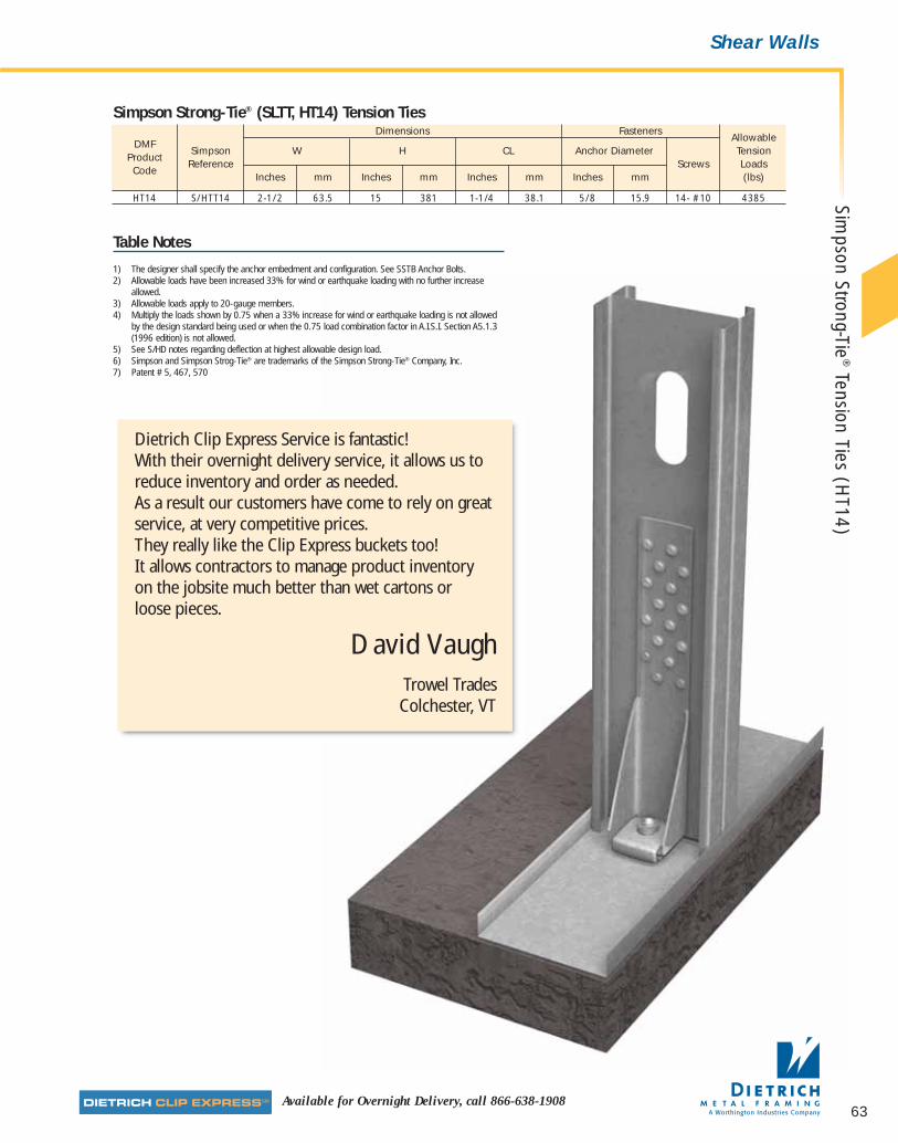
63Available for Overnight Delivery, call 866-638-1908
Shear Walls
Dimensions FastenersAllowable
DMFSimpson W H CL Anchor Diameter Tension
ProductReference Screws Loads
CodeInches mm Inches mm Inches mm Inches mm (lbs)
HT14 S/HTT14 2-1/2 63.5 15 381 1-1/4 38.1 5/8 15.9 14- #10 4385
Simpson Strong-Tie® (SLTT, HT14) Tension Ties
Table Notes
1) The designer shall specify the anchor embedment and configuration. See SSTB Anchor Bolts.2) Allowable loads have been increased 33% for wind or earthquake loading with no further increase
allowed.3) Allowable loads apply to 20-gauge members.4) Multiply the loads shown by 0.75 when a 33% increase for wind or earthquake loading is not allowed
by the design standard being used or when the 0.75 load combination factor in A.I.S.I. Section A5.1.3(1996 edition) is not allowed.
5) See S/HD notes regarding deflection at highest allowable design load.6) Simpson and Simpson Strog-Tie® are trademarks of the Simpson Strong-Tie® Company, Inc. 7) Patent # 5, 467, 570
Dietrich Clip Express Service is fantastic! With their overnight delivery service, it allows us toreduce inventory and order as needed. As a result our customers have come to rely on greatservice, at very competitive prices. They really like the Clip Express buckets too! It allows contractors to manage product inventory on the jobsite much better than wet cartons or loose pieces.
David VaughTrowel Trades
Colchester, VT
Simpson Strong-Tie
®Tension Ties (H
T14)
07856 DMF Catalog 40-81.qxd:Pgs 40-81 6/24/10 3:27 PM Page 63

64 dietrich metalframing •com The place to stop…before the building starts! SMrequest a quote online @
■ Provides racking restraint.
■ Used in shear wall assemblies.
■ Resist uplift and shear forces.
Gusset Plates and diagonal tension strapping componentsare used in combination to provide shear wall (rackingrestraint) for light-gauge load-bearing framing under windand seismic loads. They are normally installed on bothsides of the wall directly over the framing members and areeasily covered with facing materials.
CAUTION: Racking loads are first transferred to the roof orfloor decking and then to the shear walls (X-bracing). TheX-bracing then relies on a proper anchorage to thefoundation to resist uplift and shear forces. In order for thesystem to function properly, the load path from the roof orfloor deck to the shear walls to the foundation must becomplete. This normally requires additional bracing,blocking, track and rim splices, drag struts, uplift anchorsand heavy-duty foundations.
Product Dimensions6" x 6" (152mm x 152mm)6" x 12" (152mm x 305mm)12" x 12" (305mm x 305mm)
Material SpecificationsGauge: 16 gauge (54 mils)Design Thickness: 0.0566 inches (1.438mm)Gauge: 12 gauge (97 mils)Design Thickness: 0.1017 inches (2.583mm)Coating: G90 (Z275) hot-dipped galvanized coatingYield Strength: Mill-certified SS Grade 50 ksi (340 MPa)ASTM: A 653/A 653M
InstallationStraps are positioned diagonally from the bottom track to the top track. In order to resist load in each direction, an X-configuration should be used. At a minimum, doublestuds are positioned at ends of the X-brace to serve ascompression studs. Straps are either attached directly tothe compression studs or are attached via gusset plates.Compression studs must be anchored to the foundation,normally with Simpson* uplift anchors. For multistoryconstruction, the uplift loads can be extremely high. It isrecommended that you enlist the services of a qualifiedprofessional engineer to verify the applicability of thesystem selected.
Unpunched Gusset Plates are used in conjunction with X-bracing in load-bearing shear wall assemblies to resist racking under wind and seismic loads.
Gusset Plates
12"
12"
12"
6"
6"
6"
* Simpson® and Simpson Strong-Tie® are registeredtrademarks of the Simpson Strong-Tie® Company, Inc.
Unp
unch
ed G
usse
t Pla
tes
(GP)
for
Shea
r W
all B
raci
ng
07856 DMF Catalog 40-81.qxd:Pgs 40-81 6/24/10 3:27 PM Page 64
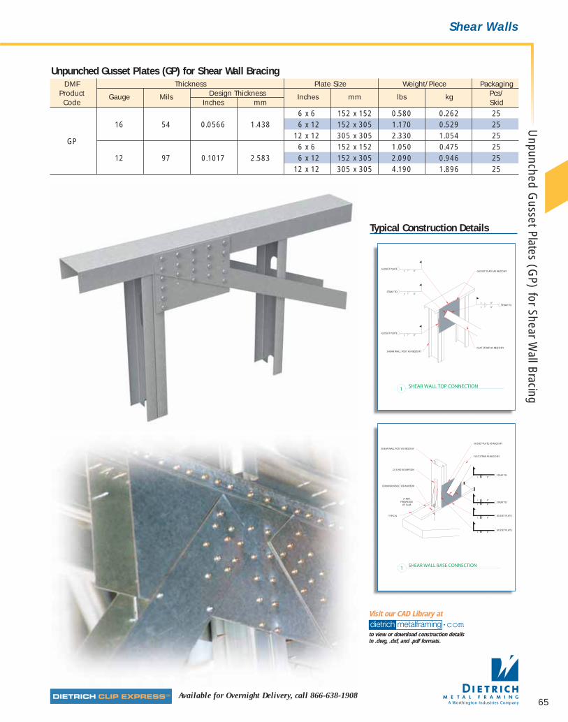
65Available for Overnight Delivery, call 866-638-1908
Shear Walls
DMF Thickness Plate Size Weight/Piece PackagingProduct Gauge Mils Design Thickness Inches mm lbs kg Pcs/Code Inches mm Skid
6 x 6 152 x 152 0.580 0.262 2516 54 0.0566 1.438 6 x 12 152 x 305 1.170 0.529 25
GP12 x 12 305 x 305 2.330 1.054 256 x 6 152 x 152 1.050 0.475 25
12 97 0.1017 2.583 6 x 12 152 x 305 2.090 0.946 2512 x 12 305 x 305 4.190 1.896 25
Unpunched Gusset Plates (GP) for Shear Wall Bracing
Typical Construction Details
dietrich metalframing •comto view or download construction details in .dwg, .dxf, and .pdf formats.
Visit our CAD Library at
Unpunched G
usset Plates (GP) for Shear W
all Bracing
07856 DMF Catalog 40-81.qxd:Pgs 40-81 6/24/10 3:27 PM Page 65
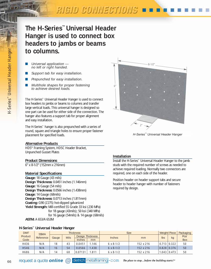
66 dietrich metalframing •com The place to stop…before the building starts! SMrequest a quote online @
■ Universal application — no left or right handed.
■ Support tab for easy installation.
■ Prepunched for easy installation.
■ Multihole shapes for proper fastening to achieve desired loads.
The H-Series™ Universal Header Hanger is used to connectbox headers to jambs or beams to columns and transferlarge vertical loads. This universal hanger is designed soone part can be used for either side of the connection. Thehanger also features a support tab for proper alignmentand easy installation.
The H-Series™ hanger is also prepunched with a series ofround, square and triangle holes to ensure proper fastenerplacement for specified loads.
Alternative ProductsHDS® Framing System, HDSC Header Bracket,Unpunched Gusset Plates
Product Dimensions6" x 8-1/2" (152mm x 216mm)
Material SpecificationsGauge: 18 Gauge (43 mils)Design Thickness: 0.0451 inches (1.146mm)Gauge: 16 Gauge (54 mils)Design Thickness: 0.0566 inches (1.438mm)Gauge: 14 Gauge (68mils)Design Thickness: 0.0713 inches (1.811mm)Coating: G90 (Z275) hot-dipped galvanizedYield Strength: Mill-certified SS Grade 33 ksi (230 MPa)
for 18 gauge (43mils); 50 ksi (340 MPa)for 16 gauge (54mils) & 14 gauge (68mils)
ASTM: A 653/A 653M
InstallationInstall the H-Series™ Universal Header Hanger to the jambstuds with the required number of screws as needed toachieve required loading. Normally two connectors arerequired, one on each side of the header.
Position header on header support tabs and secure header to header hanger with number of fasteners required by design.
The H-Series™ Universal HeaderHanger is used to connect boxheaders to jambs or beams to columns.
DMF SSMA Thickness Size Weight/Piece PackagingProduct Reference Gauge Mils Design Thickness Inches mm lbs kg Pcs/Code Inches mm BoxH436 N/A 18 43 0.0451 1.146 6 x 8-1/2 152 x 216 0.713 0.322 50H546 N/A 16 54 0.0566 1.438 6 x 8-1/2 152 x 216 0.828 0.376 50H686 N/A 14 68 0.07131 1.811 6 x 8-1/2 152 x 216 1.043 0.473 50
H-Series™ Universal Header Hanger
H-Series™ Universal Header Hanger
2"
6"
8-1/2"
H-S
erie
s™U
nive
rsal
Hea
der
Han
ger
07856 DMF Catalog 40-81.qxd:Pgs 40-81 6/24/10 3:27 PM Page 66
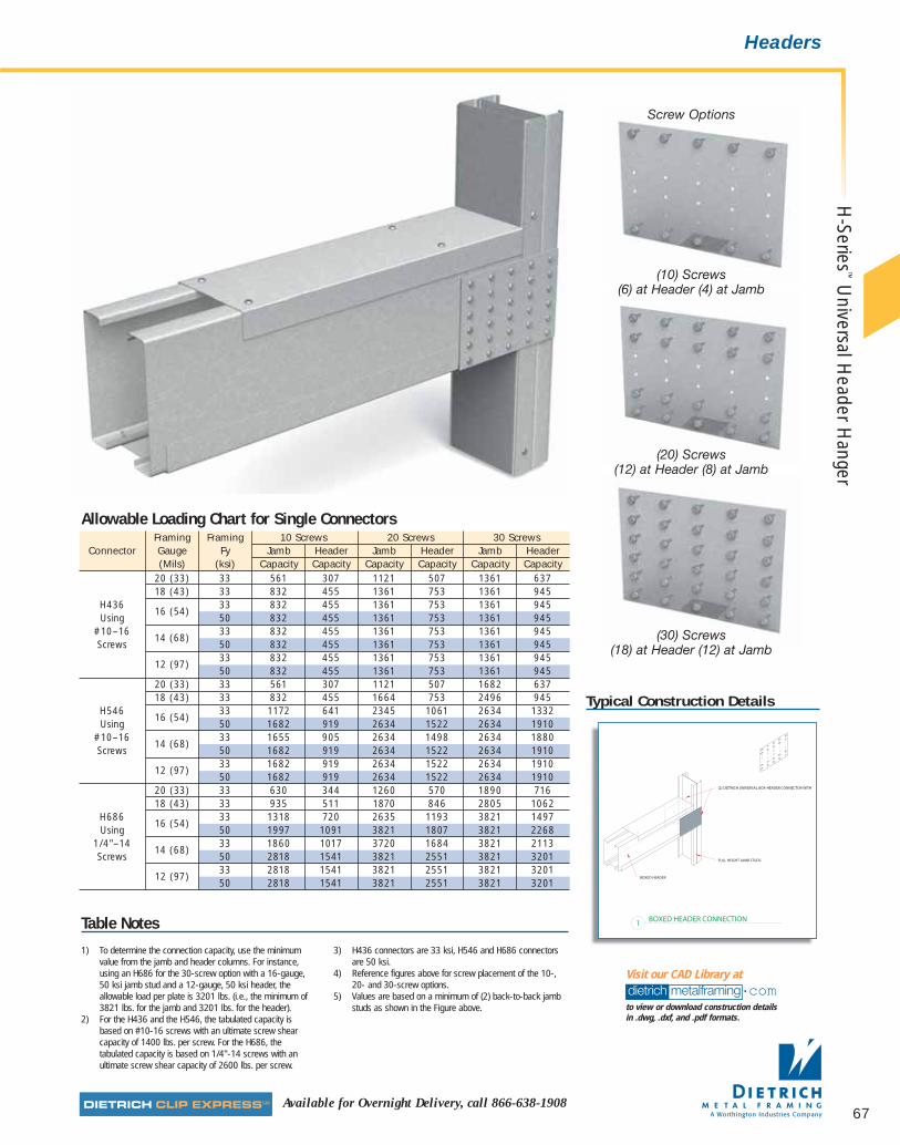
67Available for Overnight Delivery, call 866-638-1908
Headers
Framing Framing 10 Screws 20 Screws 30 ScrewsConnector Gauge Fy Jamb Header Jamb Header Jamb Header
(Mils) (ksi) Capacity Capacity Capacity Capacity Capacity Capacity20 (33) 33 561 307 1121 507 1361 63718 (43) 33 832 455 1361 753 1361 945
H43616 (54)
33 832 455 1361 753 1361 945Using 50 832 455 1361 753 1361 945
#10–1614 (68)
33 832 455 1361 753 1361 945Screws 50 832 455 1361 753 1361 945
12 (97)33 832 455 1361 753 1361 94550 832 455 1361 753 1361 945
20 (33) 33 561 307 1121 507 1682 63718 (43) 33 832 455 1664 753 2496 945
H54616 (54)
33 1172 641 2345 1061 2634 1332Using 50 1682 919 2634 1522 2634 1910
#10–1614 (68)
33 1655 905 2634 1498 2634 1880Screws 50 1682 919 2634 1522 2634 1910
12 (97)33 1682 919 2634 1522 2634 191050 1682 919 2634 1522 2634 1910
20 (33) 33 630 344 1260 570 1890 71618 (43) 33 935 511 1870 846 2805 1062
H68616 (54)
33 1318 720 2635 1193 3821 1497Using 50 1997 1091 3821 1807 3821 2268
1/4"–1414 (68)
33 1860 1017 3720 1684 3821 2113Screws 50 2818 1541 3821 2551 3821 3201
12 (97)33 2818 1541 3821 2551 3821 320150 2818 1541 3821 2551 3821 3201
Allowable Loading Chart for Single Connectors
Typical Construction Details
Table Notes
1) To determine the connection capacity, use the minimumvalue from the jamb and header columns. For instance,using an H686 for the 30-screw option with a 16-gauge,50 ksi jamb stud and a 12-gauge, 50 ksi header, theallowable load per plate is 3201 lbs. (i.e., the minimum of3821 lbs. for the jamb and 3201 lbs. for the header).
2) For the H436 and the H546, the tabulated capacity isbased on #10-16 screws with an ultimate screw shearcapacity of 1400 lbs. per screw. For the H686, thetabulated capacity is based on 1/4"-14 screws with anultimate screw shear capacity of 2600 lbs. per screw.
3) H436 connectors are 33 ksi, H546 and H686 connectorsare 50 ksi.
4) Reference figures above for screw placement of the 10-,20- and 30-screw options.
5) Values are based on a minimum of (2) back-to-back jambstuds as shown in the Figure above.
Screw Options
(10) Screws(6) at Header (4) at Jamb
(20) Screws(12) at Header (8) at Jamb
(30) Screws(18) at Header (12) at Jamb
dietrich metalframing •comto view or download construction details in .dwg, .dxf, and .pdf formats.
Visit our CAD Library at
H-Series
™U
niversal Header H
anger
07856 DMF Catalog 40-81.qxd:Pgs 40-81 6/24/10 3:27 PM Page 67
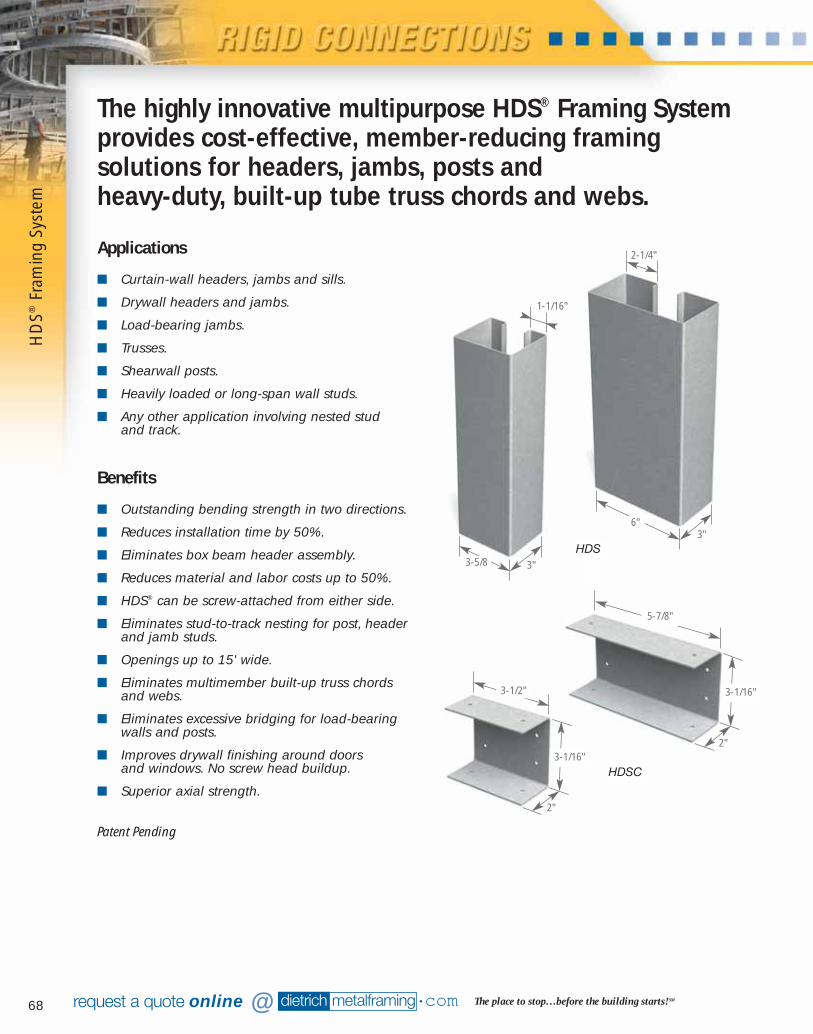
68
Benefits
■ Outstanding bending strength in two directions.
■ Reduces installation time by 50%.
■ Eliminates box beam header assembly.
■ Reduces material and labor costs up to 50%.
■ HDS® can be screw-attached from either side.
■ Eliminates stud-to-track nesting for post, headerand jamb studs.
■ Openings up to 15' wide.
■ Eliminates multimember built-up truss chordsand webs.
■ Eliminates excessive bridging for load-bearingwalls and posts.
■ Improves drywall finishing around doors and windows. No screw head buildup.
■ Superior axial strength.
dietrich metalframing •com The place to stop…before the building starts! SMrequest a quote online @
The highly innovative multipurpose HDS® Framing Systemprovides cost-effective, member-reducing framingsolutions for headers, jambs, posts and heavy-duty, built-up tube truss chords and webs.
Applications
■ Curtain-wall headers, jambs and sills.
■ Drywall headers and jambs.
■ Load-bearing jambs.
■ Trusses.
■ Shearwall posts.
■ Heavily loaded or long-span wall studs.
■ Any other application involving nested stud and track.
3"6"
3"3-5/8
2-1/4"
1-1/16"
5-7/8"
3-1/2" 3-1/16"
3-1/16"
2"
2"
HDS
HDSC
Patent Pending
HD
S®Fr
amin
g Sy
stem
07856 DMF Catalog 40-81.qxd:Pgs 40-81 6/24/10 3:27 PM Page 68
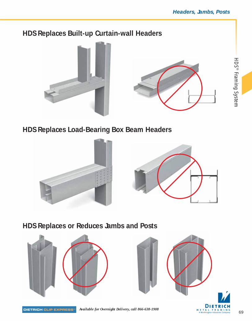
69Available for Overnight Delivery, call 866-638-1908
Headers, Jambs, Posts
HDS Replaces Built-up Curtain-wall Headers
HDS Replaces Load-Bearing Box Beam Headers
HDS Replaces or Reduces Jambs and Posts
HD
S®
Framing System
07856 DMF Catalog 40-81.qxd:Pgs 40-81 6/24/10 3:27 PM Page 69
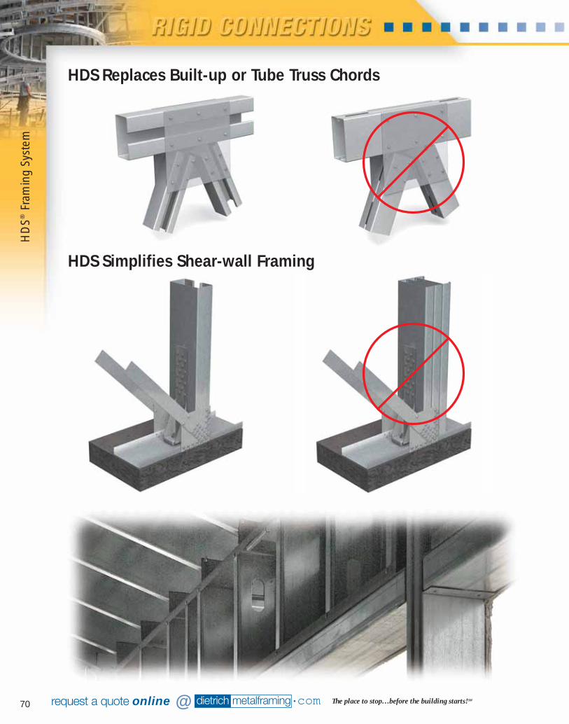
70 dietrich metalframing •com The place to stop…before the building starts! SMrequest a quote online @
HDS Replaces Built-up or Tube Truss Chords
HDS Simplifies Shear-wall Framing
HD
S®Fr
amin
g Sy
stem
07856 DMF Catalog 40-81.qxd:Pgs 40-81 6/24/10 3:27 PM Page 70
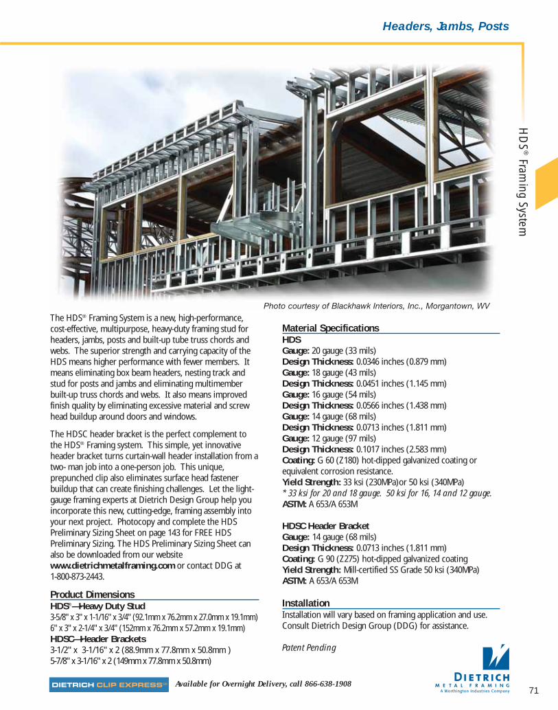
71Available for Overnight Delivery, call 866-638-1908
HD
S®
Framing System
Headers, Jambs, Posts
The HDS® Framing System is a new, high-performance, cost-effective, multipurpose, heavy-duty framing stud forheaders, jambs, posts and built-up tube truss chords andwebs. The superior strength and carrying capacity of theHDS means higher performance with fewer members. Itmeans eliminating box beam headers, nesting track andstud for posts and jambs and eliminating multimemberbuilt-up truss chords and webs. It also means improvedfinish quality by eliminating excessive material and screwhead buildup around doors and windows.
The HDSC header bracket is the perfect complement tothe HDS® Framing system. This simple, yet innovativeheader bracket turns curtain-wall header installation from atwo- man job into a one-person job. This unique,prepunched clip also eliminates surface head fastenerbuildup that can create finishing challenges. Let the light-gauge framing experts at Dietrich Design Group help youincorporate this new, cutting-edge, framing assembly intoyour next project. Photocopy and complete the HDSPreliminary Sizing Sheet on page 143 for FREE HDSPreliminary Sizing. The HDS Preliminary Sizing Sheet canalso be downloaded from our websitewww.dietrichmetalframing.com or contact DDG at 1-800-873-2443.
Product DimensionsHDS® —Heavy Duty Stud 3-5/8" x 3" x 1-1/16" x 3/4" (92.1mm x 76.2mm x 27.0mm x 19.1mm)6" x 3" x 2-1/4" x 3/4" (152mm x 76.2mm x 57.2mm x 19.1mm)HDSC—Header Brackets3-1/2" x 3-1/16" x 2 (88.9mm x 77.8mm x 50.8mm )5-7/8" x 3-1/16" x 2 (149mm x 77.8mm x 50.8mm)
Material SpecificationsHDSGauge: 20 gauge (33 mils)Design Thickness: 0.0346 inches (0.879 mm)Gauge: 18 gauge (43 mils)Design Thickness: 0.0451 inches (1.145 mm)Gauge: 16 gauge (54 mils)Design Thickness: 0.0566 inches (1.438 mm)Gauge: 14 gauge (68 mils)Design Thickness: 0.0713 inches (1.811 mm)Gauge: 12 gauge (97 mils)Design Thickness: 0.1017 inches (2.583 mm)Coating: G 60 (Z180) hot-dipped galvanized coating orequivalent corrosion resistance.Yield Strength: 33 ksi (230MPa)or 50 ksi (340MPa)* 33 ksi for 20 and 18 gauge. 50 ksi for 16, 14 and 12 gauge.ASTM: A 653/A 653M
HDSC Header BracketGauge: 14 gauge (68 mils)Design Thickness: 0.0713 inches (1.811 mm)Coating: G 90 (Z275) hot-dipped galvanized coatingYield Strength: Mill-certified SS Grade 50 ksi (340MPa)ASTM: A 653/A 653M
InstallationInstallation will vary based on framing application and use.Consult Dietrich Design Group (DDG) for assistance.
Patent Pending
Photo courtesy of Blackhawk Interiors, Inc., Morgantown, WV
07856 DMF Catalog 40-81.qxd:Pgs 40-81 6/24/10 3:27 PM Page 71

72 dietrich metalframing •com The place to stop…before the building starts! SMrequest a quote online @
WebMin.
Unperforated Section Properties Torsional PropertiesSize Ga Mils
Fy Delivered
(in)(ksi) Thickness Area Wt. Ix Sx rx Iy Sy ry Jx1000 Cw Xo Ro
(in) (in.^2) (lb./ft.) (in.^4) (in.^3) (in.) (in.^4) (in.^3) (In.) (in.^4) (in.^6) (in.) (in.) Beta20 33 33 0.0329 0.445 1.51 0.934 0.515 1.448 0.631 0.405 1.190 0.178 4.700 -3.427 3.906 0.23018 43 33 0.0428 0.574 1.94 1.198 0.661 1.444 0.805 0.516 1.184 0.389 5.896 -3.405 3.884 0.231
3.625 16 54 50 0.0538 0.715 2.41 1.483 0.818 1.441 0.990 0.632 1.177 0.764 7.093 -3.381 3.859 0.23214 68 50 0.0677 0.888 3.00 1.829 1.009 1.436 1.211 0.770 1.168 1.503 8.452 -3.349 3.827 0.23412 97 50 0.0966 1.239 4.19 2.520 1.390 1.426 1.645 1.039 1.152 4.271 10.869 -3.289 3.766 0.23720 33 33 0.0329 0.610 2.06 3.034 1.011 2.230 0.993 0.644 1.276 0.244 25.386 -3.591 4.415 0.33918 43 33 0.0428 0.788 2.66 3.907 1.302 2.226 1.273 0.824 1.271 0.533 32.231 -3.574 4.398 0.340
6 16 54 50 0.0538 0.984 3.32 4.856 1.619 2.222 1.573 1.016 1.265 1.052 39.292 -3.555 4.379 0.34114 68 50 0.0677 1.226 4.14 6.023 2.008 2.216 1.938 1.249 1.257 2.076 47.660 -3.531 4.354 0.34312 97 50 0.0966 1.722 5.82 8.380 2.793 2.206 2.662 1.707 1.243 5.936 63.365 -3.482 4.306 0.346
HDS® Properties
Unperforated Bending Properties Perforated Bending Properties Eff. Moment of InertiaWeb
Web in Ten. Web in Comp. Web in Ten. Web in Comp.Web in Web in
Size Ga Mils Sxe Mxa Sxe Mxa Ixe Ten. Comp.(in) (in.^3) (in.-lb.) Sye Mya Sye Mya (in.^3) (in.-lb.) Sye Mya Sye Mya (in.^4) Iye Iye
(in.^3) (in.-lb.) (in.^3) (in.-lb.) (in.^3) (in.-lb.) (in.^3) (in.-lb.) (in.^4) (in.^4)20 33 0.397 7846 0.401 7917 0.294 5814 0.367 7247 0.313 6192 0.243 4804 0.851 0.631 0.53718 43 0.565 11165 0.516 10187 0.425 8401 0.540 10674 0.400 7903 0.342 6753 1.161 0.805 0.741
3.625 16 54 0.711 21290 0.632 18925 0.535 16019 0.683 20464 0.492 14739 0.429 12844 1.449 0.990 0.92114 68 0.958 28672 0.770 23063 0.733 21944 0.939 28127 0.603 18051 0.572 17117 1.829 1.211 1.19412 97 1.390 41626 1.039 31111 1.039 31111 1.375 41154 0.820 24551 0.820 24551 2.520 1.645 1.64520 33 0.769 15192 0.532 10508 0.329 6505 0.752 14868 0.514 10153 0.275 5434 2.822 0.954 0.69418 43 1.150 22733 0.762 15066 0.483 9535 1.141 22553 0.697 13773 0.394 7792 3.797 1.273 0.981
6 16 54 1.449 43377 0.927 27741 0.610 18261 1.438 43053 0.865 25884 0.498 14913 4.753 1.573 1.22914 68 1.925 57642 1.226 36698 0.854 25573 1.916 57361 1.078 32268 0.686 20533 6.023 1.938 1.64512 97 2.793 83631 1.707 51102 1.429 42793 2.784 83346 1.484 44433 1.122 33607 8.380 2.662 2.522
Other PropertiesWeb
Unperforated PerforatedSize Ga Mils Lu
Vx VxVy Px Py
(in) (in)(kips) (kips)
(kips) (kips) (kips)
20 33 103 1.03 0.54 2.05 0.29 0.3818 43 103 1.74 0.68 3.09 0.46 0.61
3.625 16 54 83 3.38 1.02 5.77 1.02 1.3814 68 82 4.37 1.00 7.06 1.51 2.0812 97 82 6.05 0.92 9.71 2.85 4.0020 33 126 0.63 0.63 2.05 0.27 0.3818 43 125 1.41 1.24 3.09 0.43 0.61
6 16 54 101 2.83 1.95 5.77 0.97 1.3814 68 101 5.34 2.88 7.06 1.44 2.0812 97 100 10.58 3.90 9.71 2.74 4.00
Table Notes
Lu=Maximum unbraced length to attain Mxa.Vx=Allowable Shear for bending about x-axis.Vy=Allowable Shear for bending about y-axis.Px=Allowable Web Crippling per AISI Standard for CFSWall Stud Design 2004. This value assumes the webresists web crippling and the HDS is nested in trackhaving the same thickness. Bearing length is 1.25".Py=Allowable End One Flange Web Crippling per AISINASPEC 2001. This value assumes 2 flanges resist webcrippling for a bearing length of 1.25".
Ix=Gross Moment of Inertia about x-axis.Sx=Gross Section Modulus about x-axis.rx=Gross Radius of Gyration about x-axis.Iy=Gross Moment of Inertia about y-axis.Sy=Gross Section Modulus about y-axis.ry=Gross Radius of Gyration about y-axis.J=St. Venant Torsion Constant.Cw=Warping Torsion Constant.xo=Distance from shear center to the centroid along theprincipal x-axis.ro=Polar Radius of Gyration about the centoidal principalaxis.Beta=1-(Xo/ro)^2
Sxe=Effective Section Modulus about x-axis.Mxa=Allowable Moment about x-axis.Sye=Effective Section Modulus about y-axis.Mya=Allowable Moment about y-axis.Ixe=Effective Moment of Inertia about x-axis for deflection calculations.Iye=Effective Moment of Inertia about y-axis for deflection calculations.
Unless otherwise noted, properties are computedaccording to the AISI NASPEC, 2001.Perforated properties are based on the standard 1.5" x 4"oval Dietrich web knockout.
Clip Jamb/ Jamb/F1 (lbs) F2 (lbs)
Size Designation Head Gauge Head Gauge(Inches) Gauge (mils) Fy Jamb Head Jamb Head
20 (33) 33 560 453 560 44918 (43) 33 832 673 832 713
16 (54)33 1172 948 890 890
3.5 HDSC50 1680 1359 890 890
14 (68)33 1656 1339 890 89050 1680 1359 890 890
12 (97)33 1680 1359 890 89050 1680 1359 890 890
20 (33) 33 560 501 560 44918 (43) 33 832 744 832 713
16 (54)33 1172 1048 1172 1064
5-7/8 HDSC50 1680 1503 1493 1493
14 (68)33 1656 1481 1493 149350 1680 1503 1493 1493
12 (97)33 1680 1503 1493 149350 1680 1503 1493 1493
Allowable Loads for HDSC Header Brackets (lbs)
Table Notes
1) Screws shall be #10-16 Buildex or equivalent, with an ultimate shear capacity per screw of 1400#.2) Table to be used by qualified engineers only.3) To determine the capacity of any given connection, compare the jamb and head values, and use the minimum. For example, if a 16-gauge, 50 ksi jamb is used with a
3.625" HDS 18-gauge, 33 ksi head, the design value for F1 is the minimum value of 1680# for the jamb and 682# for the head. Therefore, the design value is 682#.4) For F1 and F2 occurring at the same time, use the squared interaction equation: (f1/F1)^2+(f2/F2)^2<1.0.
Patent Pending
HD
S®Fr
amin
g Sy
stem
07856 DMF Catalog 40-81.qxd:Pgs 40-81 6/24/10 3:27 PM Page 72

73Available for Overnight Delivery, call 866-638-1908
Headers, Jambs, Posts
WallDeflection
HeightMember
GaugeMils Fy 240 360 600
(ft)Size (in) (ksi) Opening Height (ft)(in)
8 10 12 14 8 10 12 14 8 10 12 1420 33 33 11' 0'' — — — 10' 4'' — — — 9' 6'' — — —18 43 33 11' 6'' — — — 10' 10'' — — — 10' 0'' — — —
3.625 16 54 50 11' 11'' — — — 11' 3'' — — — 10' 4'' — — —14 68 50 12' 3'' — — — 11' 7'' — — — 10' 9'' — — —
912 97 50 12' 10'' — — — 12' 2'' — — — 11' 3'' — — —20 33 33 12' 12'' — — — 12' 4'' — — — 11' 6'' — — —18 43 33 13' 5'' — — — 12' 10'' — — — 11' 12'' — — —
6 16 54 50 13' 9'' — — — 13' 2'' — — — 12' 4'' — — —14 68 50 14' 1'' — — — 13' 6'' — — — 12' 9'' — — —12 97 50 14' 5'' — — — 13' 11'' — — — 13' 3'' — — —20 33 33 9' 2'' 11' 12'' — — 9' 2'' 11' 3'' — — 9' 2'' 10' 5'' — —18 43 33 10' 6'' 12' 7'' — — 10' 6'' 11' 9'' — — 9' 11'' 10' 11'' — —
3.625 16 54 50 11' 11'' 13' 0'' — — 11' 2'' 12' 2'' — — 10' 4'' 11' 3'' — —14 68 50 12' 3'' 13' 6'' — — 11' 7'' 12' 8'' — — 10' 9'' 11' 8'' — —
1112 97 50 12' 10'' * 14' 2'' — — 12' 2'' 13' 4'' — — 11' 3'' 12' 3'' — —20 33 33 12' 0'' 14' 5'' — — 12' 0'' 13' 7'' — — 11' 6'' 12' 6'' — —18 43 33 12' 11'' * 15' 0'' — — 12' 10'' * 14' 2'' — — 11' 12'' 13' 1'' — —
6 16 54 50 13' 7'' * 15' 6'' — — 13' 2'' * 14' 8'' — — 12' 4'' 13' 7'' — —14 68 50 14' 1'' * 15' 11'' — — 13' 6'' * 15' 2'' — — 12' 9'' * 14' 1'' — —12 97 50 14' 5'' * 16' 7'' — — 13' 11'' * 15' 10'' — — 13' 3'' * 14' 9'' — —20 33 33 7' 7'' 9' 2'' 11' 11'' — 7' 7'' 9' 2'' 11' 11'' — 7' 7'' 9' 2'' 10' 6'' —18 43 33 8' 8'' * 10' 5'' 13' 6'' — 8' 8'' * 10' 5'' 12' 8'' — 8' 8'' * 10' 5'' 11' 4'' —
3.625 16 54 50 10' 8'' * 12' 2'' 13' 11'' — 10' 8'' * 12' 2'' 13' 1'' — 10' 3'' * 11' 1'' 12' 2'' —14 68 50 11' 3'' * 12' 9'' * 14' 5'' — 11' 3'' * 12' 7'' * 13' 7'' — 10' 8'' * 11' 7'' 12' 7'' —
1312 97 50 12' 1'' * 13' 9'' * 15' 2'' — 12' 1'' * 13' 3'' * 14' 3'' — 11' 3'' * 12' 3'' 13' 2'' —20 33 33 9' 11'' * 11' 10'' 15' 6'' — 9' 11'' * 11' 10'' 14' 6'' — 9' 11'' * 11' 10'' 13' 5'' —18 43 33 11' 4'' * 12' 11'' * 16' 2'' — 11' 4'' * 12' 11'' * 15' 2'' — 11' 4'' * 12' 11'' * 14' 0'' —
6 16 54 50 11' 12'' * 13' 7'' * 16' 9'' — 11' 12'' * 13' 7'' * 15' 9'' — 11' 12'' * 13' 7'' * 14' 6'' —14 68 50 12' 8'' * 14' 4'' * 17' 4'' — 12' 8'' * 14' 4'' * 16' 4'' — 12' 8'' * 14' 1'' * 15' 1'' —12 97 50 13' 8'' * 15' 6'' * 18' 2'' — 13' 8'' * 15' 6'' * 17' 2'' — 13' 3'' * 14' 9'' * 15' 11'' —20 33 33 6' 7'' * 7' 7'' 9' 2'' 11' 11'' 6' 7'' * 7' 7'' 9' 2'' 11' 11'' 6' 7'' * 7' 7'' 9' 2'' 10' 6''18 43 33 7' 7'' * 8' 8'' * 10' 5'' 13' 7'' 7' 7'' * 8' 8'' * 10' 5'' 12' 12'' 7' 7'' * 8' 8'' * 10' 5'' 11' 4''
3.625 16 54 50 9' 9'' * 10' 8'' * 12' 2'' 14' 10'' 9' 9'' * 10' 8'' * 12' 2'' 13' 9'' 9' 9'' * 10' 8'' * 11' 5'' 12' 0''14 68 50 10' 4'' * 11' 3'' * 12' 9'' * 15' 4'' 10' 4'' * 11' 3'' * 12' 9'' * 14' 6'' 10' 4'' * 11' 3'' * 12' 3'' * 12' 9''
1512 97 50 11' 2'' * 12' 1'' * 13' 9'' * 16' 1'' 11' 2'' * 12' 1'' * 13' 9'' * 15' 2'' 11' 2'' * 12' 1'' * 12' 12'' * 13' 11''20 33 33 8' 7'' * 9' 10'' * 11' 10'' 15' 4'' 8' 7'' * 9' 10'' * 11' 10'' 15' 4'' 8' 7'' * 9' 10'' * 11' 10'' 14' 4''18 43 33 10' 1'' * 11' 4'' * 12' 11'' * 16' 12'' 10' 1'' * 11' 4'' * 12' 11'' * 16' 1'' 10' 1'' * 11' 4'' * 12' 11'' * 14' 11''
6 16 54 50 11' 0'' * 11' 12'' * 13' 7'' * 17' 9'' * 11' 0'' * 11' 12'' * 13' 7'' * 16' 8'' 11' 0'' * 11' 12'' * 13' 7'' * 15' 5''14 68 50 11' 7'' * 12' 8'' * 14' 4'' * 18' 5'' * 11' 7'' * 12' 8'' * 14' 4'' * 17' 4'' 11' 7'' * 12' 8'' * 14' 4'' * 15' 12''12 97 50 12' 7'' * 13' 8'' * 15' 6'' * 19' 5'' * 12' 7'' * 13' 8'' * 15' 6'' * 18' 3'' * 12' 7'' * 13' 8'' * 15' 6'' * 16' 10''
Interior Span ChartAllowable HDS® Header Spans for Window and Door Openings (Dead Load=10psf & Wind Load=5psf)(Dead Load Deflection Limited to L/240 or a Maximum of 0.5 in.)
Table Notes
1) Tabulated values are for a single HDSheader installed with standard HDSclips. Each head-to-jamb connectionrequires (4) #10-16 screws to theheader, and (4) #10-16 screws to thejamb. Tabulated values marked with anasterisk will require special engineeringof the header-to-jamb connections.
2) Tabulated values include a connectioncheck assuming 25 gauge jamb studs.
3) HDS Header to be installed with openside facing up.
4) HDS properties computed inaccordance with AISI NASPEC 2001.
WallHeight
Opening
HDS Header
Header Span
OpeningHeight
F1
F2
Patent Pending
HD
S®
Framing System
07856 DMF Catalog 40-81.qxd:Pgs 40-81 6/24/10 3:27 PM Page 73
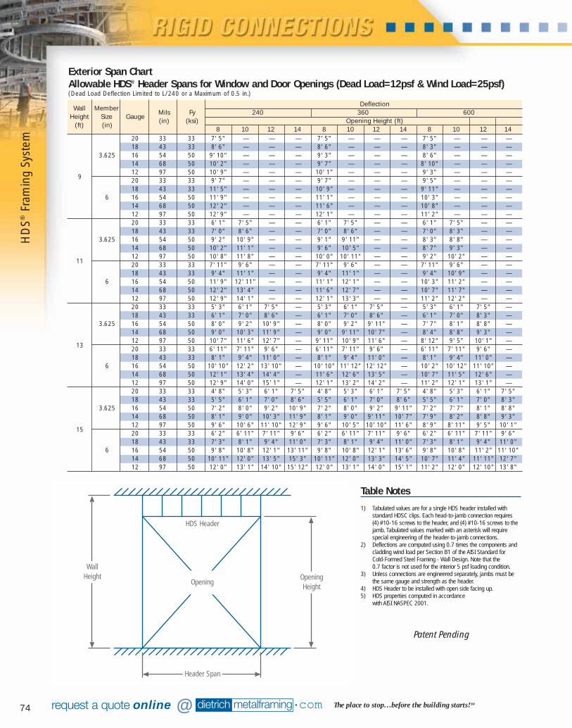
74 dietrich metalframing •com The place to stop…before the building starts! SMrequest a quote online @
WallDeflection
HeightMember
GaugeMils Fy 240 360 600
(ft)Size
(in) (ksi) Opening Height (ft)(in)
8 10 12 14 8 10 12 14 8 10 12 1420 33 33 7' 5" — — — 7' 5" — — — 7' 5" — — —18 43 33 8' 6" — — — 8' 6" — — — 8' 3" — — —
3.625 16 54 50 9' 10" — — — 9' 3" — — — 8' 6" — — —14 68 50 10' 2" — — — 9' 7" — — — 8' 10" — — —12 97 50 10' 9" — — — 10' 1" — — — 9' 3" — — —
9 20 33 33 9' 7" — — — 9' 7" — — — 9' 5" — — —18 43 33 11' 5" — — — 10' 9" — — — 9' 11" — — —
6 16 54 50 11' 9" — — — 11' 1" — — — 10' 3" — — —14 68 50 12' 2" — — — 11' 6" — — — 10' 8" — — —12 97 50 12' 9" — — — 12' 1" — — — 11' 2" — — —20 33 33 6' 1" 7' 5" — — 6' 1" 7' 5" — — 6' 1" 7' 5" — —18 43 33 7' 0" 8' 6" — — 7' 0" 8' 6" — — 7' 0" 8' 3" — —
3.625 16 54 50 9' 2" 10' 9" — — 9' 1" 9' 11" — — 8' 3" 8' 8" — —14 68 50 10' 2" 11' 1" — — 9' 6" 10' 5" — — 8' 7" 9' 3" — —12 97 50 10' 8" 11' 8" — — 10' 0" 10' 11" — — 9' 2" 10' 2" — —
11 20 33 33 7' 11" 9' 6" — — 7' 11" 9' 6" — — 7' 11" 9' 6" — —18 43 33 9' 4" 11' 1" — — 9' 4" 11' 1" — — 9' 4" 10' 9" — —
6 16 54 50 11' 9" 12' 11" — — 11' 1" 12' 1" — — 10' 3" 11' 2" — —14 68 50 12' 2" 13' 4" — — 11' 6" 12' 7" — — 10' 7" 11' 7" — —12 97 50 12' 9" 14' 1" — — 12' 1" 13' 3" — — 11' 2" 12' 2" — —20 33 33 5' 3" 6' 1" 7' 5" — 5' 3" 6' 1" 7' 5" — 5' 3" 6' 1" 7' 5" —18 43 33 6' 1" 7' 0" 8' 6" — 6' 1" 7' 0" 8' 6" — 6' 1" 7' 0" 8' 3" —
3.625 16 54 50 8' 0" 9' 2" 10' 9" — 8' 0" 9' 2" 9' 11" — 7' 7" 8' 1" 8' 8" —14 68 50 9' 0" 10' 3" 11' 9" — 9' 0" 9' 11" 10' 7" — 8' 4" 8' 8" 9' 3" —12 97 50 10' 7" 11' 6" 12' 7" — 9' 11" 10' 9" 11' 6" — 8' 12" 9' 5" 10' 1" —
13 20 33 33 6' 11" 7' 11" 9' 6" — 6' 11" 7' 11" 9' 6" — 6' 11" 7' 11" 9' 6" —18 43 33 8' 1" 9' 4" 11' 0" — 8' 1" 9' 4" 11' 0" — 8' 1" 9' 4" 11' 0" —
6 16 54 50 10' 10" 12' 2" 13' 10" — 10' 10" 11' 12" 12' 12" — 10' 2" 10' 12" 11' 10" —14 68 50 12' 1" 13' 4" 14' 4" — 11' 6" 12' 6" 13' 5" — 10' 7" 11' 5" 12' 6" —12 97 50 12' 9" 14' 0" 15' 1" — 12' 1" 13' 2" 14' 2" — 11' 2" 12' 1" 13' 1" —20 33 33 4' 8" 5' 3" 6' 1" 7' 5" 4' 8" 5' 3" 6' 1" 7' 5" 4' 8" 5' 3" 6' 1" 7' 5"18 43 33 5' 5" 6' 1" 7' 0" 8' 6" 5' 5" 6' 1" 7' 0" 8' 6" 5' 5" 6' 1" 7' 0" 8' 3"
3.625 16 54 50 7' 2" 8' 0" 9' 2" 10' 9" 7' 2" 8' 0" 9' 2" 9' 11" 7' 2" 7' 7" 8' 1" 8' 8"14 68 50 8' 1" 9' 0" 10' 3" 11' 9" 8' 1" 9' 0" 9' 11" 10' 7" 7' 9" 8' 2" 8' 8" 9' 3"12 97 50 9' 6" 10' 6" 11' 10" 12' 9" 9' 6" 10' 5" 10' 10" 11' 6" 8' 9" 8' 11" 9' 5" 10' 1"
15 20 33 33 6' 2" 6' 11" 7' 11" 9' 6" 6' 2" 6' 11" 7' 11" 9' 6" 6' 2" 6' 11" 7' 11" 9' 6"18 43 33 7' 3" 8' 1" 9' 4" 11' 0" 7' 3" 8' 1" 9' 4" 11' 0" 7' 3" 8' 1" 9' 4" 11' 0"
6 16 54 50 9' 8" 10' 8" 12' 1" 13' 11" 9' 8" 10' 8" 12' 1" 13' 6" 9' 8" 10' 8" 11' 2" 11' 10"14 68 50 10' 11" 12' 0" 13' 5" 15' 3" 10' 11" 12' 0" 13' 3" 14' 5" 10' 7" 11' 4" 11' 11" 12' 7"12 97 50 12' 0" 13' 1" 14' 10" 15' 12" 12' 0" 13' 1" 14' 0" 15' 1" 11' 2" 12' 0" 12' 10" 13' 8"
Exterior Span ChartAllowable HDS® Header Spans for Window and Door Openings (Dead Load=12psf & Wind Load=25psf)(Dead Load Deflection Limited to L/240 or a Maximum of 0.5 in.)
WallHeight
Opening
HDS Header
Header Span
OpeningHeight
Table Notes
1) Tabulated values are for a single HDS header installed withstandard HDSC clips. Each head-to-jamb connection requires (4) #10-16 screws to the header, and (4) #10-16 screws to thejamb. Tabulated values marked with an asterisk will requirespecial engineering of the header-to-jamb connections.
2) Deflections are computed using 0.7 times the components andcladding wind load per Section B1 of the AISI Standard for Cold-Formed Steel Framing - Wall Design. Note that the 0.7 factor is not used for the interior 5 psf loading condition.
3) Unless connections are engineered separately, jambs must bethe same gauge and strength as the header.
4) HDS Header to be installed with open side facing up.5) HDS properties computed in accordance
with AISI NASPEC 2001.
Patent Pending
HD
S®Fr
amin
g Sy
stem
07856 DMF Catalog 40-81.qxd:Pgs 40-81 6/24/10 3:27 PM Page 74
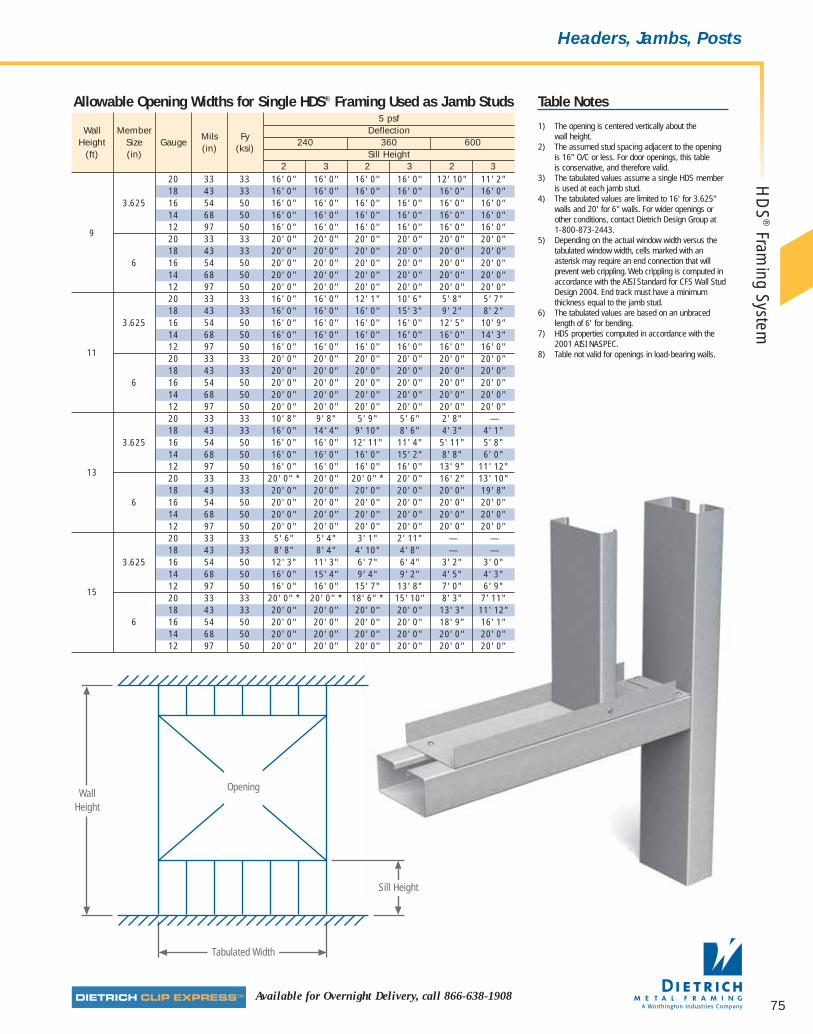
75Available for Overnight Delivery, call 866-638-1908
Headers, Jambs, Posts
Table Notes
1) The opening is centered vertically about the wall height.
2) The assumed stud spacing adjacent to the opening is 16" O/C or less. For door openings, this table is conservative, and therefore valid.
3) The tabulated values assume a single HDS memberis used at each jamb stud.
4) The tabulated values are limited to 16' for 3.625"walls and 20' for 6" walls. For wider openings orother conditions, contact Dietrich Design Group at 1-800-873-2443.
5) Depending on the actual window width versus thetabulated window width, cells marked with anasterisk may require an end connection that willprevent web crippling. Web crippling is computed inaccordance with the AISI Standard for CFS Wall StudDesign 2004. End track must have a minimumthickness equal to the jamb stud.
6) The tabulated values are based on an unbracedlength of 6' for bending.
7) HDS properties computed in accordance with the2001 AISI NASPEC.
8) Table not valid for openings in load-bearing walls.
5 psfWall Member
Mils FyDeflection
Height Size Gauge(in) (ksi)
240 360 600(ft) (in) Sill Height
2 3 2 3 2 320 33 33 16' 0'' 16' 0'' 16' 0'' 16' 0'' 12' 10" 11' 2"18 43 33 16' 0'' 16' 0'' 16' 0'' 16' 0'' 16' 0'' 16' 0''
3.625 16 54 50 16' 0'' 16' 0'' 16' 0'' 16' 0'' 16' 0'' 16' 0''14 68 50 16' 0'' 16' 0'' 16' 0'' 16' 0'' 16' 0'' 16' 0''
912 97 50 16' 0'' 16' 0'' 16' 0'' 16' 0'' 16' 0'' 16' 0''20 33 33 20' 0'' 20' 0'' 20' 0'' 20' 0'' 20' 0'' 20' 0''18 43 33 20' 0'' 20' 0'' 20' 0'' 20' 0'' 20' 0'' 20' 0''
6 16 54 50 20' 0'' 20' 0'' 20' 0'' 20' 0'' 20' 0'' 20' 0''14 68 50 20' 0'' 20' 0'' 20' 0'' 20' 0'' 20' 0'' 20' 0''12 97 50 20' 0'' 20' 0'' 20' 0'' 20' 0'' 20' 0'' 20' 0''20 33 33 16' 0'' 16' 0'' 12' 1" 10' 6" 5' 8" 5' 7"18 43 33 16' 0'' 16' 0'' 16' 0'' 15' 3" 9' 2" 8' 2"
3.625 16 54 50 16' 0'' 16' 0'' 16' 0'' 16' 0'' 12' 5" 10' 9"14 68 50 16' 0'' 16' 0'' 16' 0'' 16' 0'' 16' 0'' 14' 3"
1112 97 50 16' 0'' 16' 0'' 16' 0'' 16' 0'' 16' 0'' 16' 0''20 33 33 20' 0'' 20' 0'' 20' 0'' 20' 0'' 20' 0'' 20' 0''18 43 33 20' 0'' 20' 0'' 20' 0'' 20' 0'' 20' 0'' 20' 0''
6 16 54 50 20' 0'' 20' 0'' 20' 0'' 20' 0'' 20' 0'' 20' 0''14 68 50 20' 0'' 20' 0'' 20' 0'' 20' 0'' 20' 0'' 20' 0''12 97 50 20' 0'' 20' 0'' 20' 0'' 20' 0'' 20' 0'' 20' 0''20 33 33 10' 8" 9' 8" 5' 9" 5' 6" 2' 8" —18 43 33 16' 0'' 14' 4" 9' 10" 8' 6" 4' 3" 4' 1"
3.625 16 54 50 16' 0'' 16' 0'' 12' 11" 11' 4" 5' 11" 5' 8"14 68 50 16' 0'' 16' 0'' 16' 0'' 15' 2" 8' 8" 6' 0"
1312 97 50 16' 0'' 16' 0'' 16' 0'' 16' 0'' 13' 9" 11' 12"20 33 33 20' 0'' * 20' 0'' 20' 0'' * 20' 0'' 16' 2" 13' 10"18 43 33 20' 0'' 20' 0'' 20' 0'' 20' 0'' 20' 0'' 19' 8"
6 16 54 50 20' 0'' 20' 0'' 20' 0'' 20' 0'' 20' 0'' 20' 0''14 68 50 20' 0'' 20' 0'' 20' 0'' 20' 0'' 20' 0'' 20' 0''12 97 50 20' 0'' 20' 0'' 20' 0'' 20' 0'' 20' 0'' 20' 0''20 33 33 5' 6" 5' 4" 3' 1" 2' 11" — —18 43 33 8' 8" 8' 4" 4' 10" 4' 8" — —
3.625 16 54 50 12' 3" 11' 3" 6' 7" 6' 4" 3' 2" 3' 0"14 68 50 16' 0'' 15' 4" 9' 4" 9' 2" 4' 5" 4' 3"
1512 97 50 16' 0'' 16' 0'' 15' 7" 13' 8" 7' 0" 6' 9"20 33 33 20' 0'' * 20' 0'' * 18' 6" * 15' 10" 8' 3" 7' 11"18 43 33 20' 0'' 20' 0'' 20' 0'' 20' 0'' 13' 3" 11' 12"
6 16 54 50 20' 0'' 20' 0'' 20' 0'' 20' 0'' 18' 9" 16' 1"14 68 50 20' 0'' 20' 0'' 20' 0'' 20' 0'' 20' 0'' 20' 0''12 97 50 20' 0'' 20' 0'' 20' 0'' 20' 0'' 20' 0'' 20' 0''
Allowable Opening Widths for Single HDS® Framing Used as Jamb Studs
WallHeight
Opening
Tabulated Width
Sill Height
HD
S®
Framing System
07856 DMF Catalog 40-81.qxd:Pgs 40-81 6/24/10 3:27 PM Page 75

76 dietrich metalframing •com The place to stop…before the building starts! SMrequest a quote online @
25 psf 35 psfWall Member
Mils FyDeflection Deflection
Height Size Gauge(in) (ksi)
240 360 600 240 360 600(ft) (in) Sill Height Sill Height
2 3 2 3 2 3 2 3 2 3 2 320 33 33 3' 3" 3' 0" 3' 3" 3' 0" — — — — — — — — 18 43 33 6' 4" 5' 4" 6' 4" 5' 4" 3' 4" 3' 1" 3' 7" 3' 4" 3' 7" 3' 4" — —
3.625 16 54 50 13' 6" 11' 6" 9' 10" 8' 8" 4' 11" 4' 3" 9' 3" 7' 9" 6' 2" 5' 6" 2' 9" —14 68 50 16' 0'' 14' 11" 13' 2" 11' 6" 6' 9" 5' 12" 11' 2" 10' 3" 8' 7" 7' 7" 3' 12" 3' 10"12 97 50 16' 0'' 16' 0'' 16' 0'' 16' 0'' 10' 5" 9' 1" 12' 1" 12' 5" 12' 1" 11' 3" 6' 7" 5' 10"
9 20 33 33 8' 9" * 7' 7" * 8' 9" * 7' 7" * 8' 9" * 7' 7" * 4' 0" * 4' 11" * 4' 0" * 4' 11" * 4' 0" * 4' 11" *18 43 33 15' 8" * 13' 2" * 15' 8" * 13' 2" * 15' 8" * 13' 2" * 10' 9" * 8' 10" * 10' 9" * 8' 10" * 10' 9" * 8' 10" *
6 16 54 50 20' 0" 20' 0" 20' 0" 20' 0" 20' 0" 19' 3" 20' 0" * 17' 9" * 20' 0" * 17' 9" * 15' 0" * 13' 1"14 68 50 20' 0" 20' 0" 20' 0" 20' 0" 20' 0" 20' 0" 20' 0" 20' 0" 20' 0" 20' 0" 19' 10" 17' 2"12 97 50 20' 0" 20' 0" 20' 0" 20' 0" 20' 0" 20' 0" 20' 0" 20' 0" 20' 0" 20' 0" 20' 0" 20' 0"20 33 33 — — — — — — — — — — — — 18 43 33 3' 3" 2' 12" 2' 11" 2' 8" — — — — — — — —
3.625 16 54 50 6' 0" 6' 12" 4' 2" 3' 10" — — 4' 7" 4' 4" — — — — 14 68 50 10' 10" 9' 6" 5' 11" 5' 9" 2' 8" — 6' 10" 6' 1" 3' 6" 3' 3" — — 12 97 50 13' 2" 13' 1" 9' 7" 8' 6" 4' 5" 4' 1" 9' 1" 8' 11" 5' 9" 5' 7" 2' 7" —
11 20 33 33 5' 6" * 5' 5" * 5' 6" * 5' 5" * 5' 3" * 5' 1" * 3' 3" * 2' 11" * 3' 3" * 2' 11" * 3' 2" * 2' 10" *18 43 33 10' 12" * 9' 5" * 10' 12" * 9' 5" * 8' 3" * 7' 5" * 6' 6" * 4' 0" * 6' 6" * 4' 0" * 4' 12" * 4' 9" *
6 16 54 50 20' 0" * 18' 10" * 20' 0" * 18' 3" * 11' 5" 9' 11" 15' 4" * 12' 12" * 14' 5" * 12' 4" * 7' 4" 6' 5"14 68 50 20' 0" 20' 0" 20' 0" 20' 0" 15' 7" 13' 3" 20' 0" * 18' 4" 19' 5" * 16' 3" 9' 11" 8' 9"12 97 50 20' 0" 20' 0" 20' 0" 20' 0" 20' 0" 19' 6" 20' 0" 20' 0" 20' 0" 20' 0" 15' 6" 13' 2"20 33 33 — — — — — — — — — — — — 18 43 33 — — — — — — — — — — — —
3.625 16 54 50 3' 7" 3' 5" — — — — — — — — — — 14 68 50 5' 1" 4' 10" 2' 9" 2' 7" — — 3' 1" 2' 11" — — — — 12 97 50 8' 4" 6' 0" 4' 6" 4' 3" — — 4' 12" 4' 9" 2' 8" 2' 6" — —
13 20 33 33 3' 3" * 3' 1" * 3' 3" * 3' 1" * — — — — — — — — 18 43 33 6' 2" * 5' 11" * 6' 2" * 5' 11" * 3' 10" 3' 8" 3' 9" * 3' 6" * 3' 9" * 3' 6" * — —
6 16 54 50 17' 9" * 14' 9" * 11' 9" 10' 5" 5' 5" 5' 2" 10' 4" * 9' 5" * 6' 12" 6' 9" 3' 3" 3' 1"14 68 50 20' 0" 20' 0" 16' 6" 14' 1" 7' 8" 7' 6" 16' 6" * 14' 0" 10' 1" 9' 2" 4' 8" 4' 5"12 97 50 20' 0" 20' 0" 20' 0" 20' 0" 12' 9" 11' 3" 20' 0" 20' 0" 16' 4" 13' 12" 7' 7" 7' 5"20 33 33 — — — — — — — — — — — — 18 43 33 — — — — — — — — — — — —
3.625 16 54 50 — — — — — — — — — — — — 14 68 50 2' 8" 2' 7" — — — — — — — — — — 12 97 50 4' 4" 4' 2" — — — — 2' 7" — — — — —
15 20 33 33 — — — — — — — — — — — — 18 43 33 4' 0" * 3' 11" * 4' 0" * 3' 11" * — — — — — — — —
6 16 54 50 11' 3" * 10' 2" 5' 12" 5' 10" 2' 10" 2' 9" 6' 3" 6' 1" 3' 9" 3' 7" — — 14 68 50 16' 2" * 14' 2" 8' 6" 8' 2" 4' 1" 3' 11" 9' 5" 9' 3" 5' 3" 5' 1" — — 12 97 50 20' 0" 20' 0" 14' 5" 12' 10" 6' 6" 6' 3" 16' 0" 14' 0" 8' 5" 8' 0" 4' 0" 3' 10"
Allowable Opening Widths for Single HDS® Framing Used as Jamb Studs
WallHeight
Opening
Tabulated Width
Sill Height
Table Notes
1) The opening is centered vertically about the wall height.2) The assumed stud spacing adjacent to the opening is 16" O/C or less.3) The tabulated values assume a single HDS member is used at each
jamb stud.4) The tabulated values are limited to 16' for 3.625" walls and 20' for
6" walls. For wider openings or other conditions, contact DietrichDesign Group at 1-800-873-2443.
5) Depending on the actual window width versus the tabulated windowwidth, cells marked with an asterisk may require an end connectionthat will prevent web crippling. Web crippling is computed inaccordance with the AISI Standard for CFS Wall Stud Design 2004. End track must have a minimum thickness equal to the jamb stud.
6) The tabulated values are based on an unbraced length for bending of 6'.
7) Deflections are computed using 0.7 times the components andcladding wind load per Section B1 of the AISI Standard for Cold-Formed Steel Framing - Wall Design. Note that the 0.7 factor is not used for the interior 5 psf loading condition.
8) HDS properties computed in accordance with the 2001 AISI NASPEC.9) Table not valid for openings in load-bearing walls.
Patent Pending
HD
S®Fr
amin
g Sy
stem
07856 DMF Catalog 40-81.qxd:Pgs 40-81 6/24/10 3:27 PM Page 76

77Available for Overnight Delivery, call 866-638-1908
Headers, Jambs, Posts
25 psf 35 psfWall Member
Mils FyDeflection Deflection
Height Size Gauge(in) (ksi)
240 360 600 240 360 600(ft) (in) Sill Height Sill Height
2 3 2 3 2 3 2 3 2 3 2 320 33 33 8' 2" 6' 10" 8' 2" 6' 10" 4' 8" 4' 1" 5' 0" 4' 2" 5' 0" 4' 2" 2' 7" — 18 43 33 13' 4" 10' 8" 13' 4" 10' 8" 6' 11" 6' 2" 8' 5" 7' 0" 8' 5" 7' 0" 4' 2" 3' 12"
3.625 16 54 50 16' 0'' 16' 0'' 16' 0'' 15' 3" 9' 4" 8' 3" 14' 11" 12' 5" 11' 8" 10' 3" 4' 0" 5' 3" 14 68 50 16' 0'' 16' 0'' 16' 0'' 16' 0'' 12' 5" 10' 10" 16' 0'' 15' 10" 15' 4" 13' 4" 7' 12" 7' 1" 12 97 50 16' 0'' 16' 0'' 16' 0'' 16' 0'' 16' 0'' 15' 8" 16' 0'' 16' 0'' 16' 0'' 16' 0'' 12' 1" 10' 6"
9 20 33 33 17' 7" * 15' 3" * 17' 7" * 15' 3" * 17' 7" * 15' 3" * 12' 2" * 10' 5" * 12' 2" * 10' 5" * 12' 2" * 10' 5" *18 43 33 20' 0" * 20' 0" 20' 0" * 20' 0" 20' 0" * 20' 0" 20' 0" * 17' 3" * 20' 0" * 17' 3" * 20' 0" * 17' 3" *
6 16 54 50 20' 0" 20' 0" 20' 0" 20' 0" 20' 0" 20' 0" 20' 0" 20' 0" 20' 0" 20' 0" 20' 0" 20' 0" 14 68 50 20' 0" 20' 0" 20' 0" 20' 0" 20' 0" 20' 0" 20' 0" 20' 0" 20' 0" 20' 0" 20' 0" 20' 0" 12 97 50 20' 0" 20' 0" 20' 0" 20' 0" 20' 0" 20' 0" 20' 0" 20' 0" 20' 0" 20' 0" 20' 0" 20' 0" 20 33 33 4' 3" 3' 12" 3' 11" 3' 8" — — — — — — — — 18 43 33 6' 0" 6' 11" 6' 2" 5' 12" 2' 10" 2' 6" 4' 5" 4' 2" 3' 8" 3' 5" — —
3.625 16 54 50 14' 11" 12' 8" 8' 6" 7' 8" 3' 11" 3' 7" 9' 5" 8' 4" 5' 1" 4' 11" — — 14 68 50 16' 0'' 16' 0'' 11' 8" 10' 2" 5' 6" 5' 4" 12' 10" 11' 1" 7' 7" 6' 6" 3' 3" 3' 0" 12 97 50 16' 0'' 16' 0'' 16' 0'' 14' 10" 8' 10" 7' 11" 15' 3" 14' 5" 11' 4" 9' 11" 5' 4" 5' 1"
11 20 33 33 13' 4" * 11' 1" * 13' 4" * 11' 1" * 11' 0" * 9' 7" * 8' 3" * 7' 4" * 8' 3" * 7' 4" * 6' 12" * 6' 2" *18 43 33 20' 0" * 18' 4" * 20' 0" * 18' 4" * 15' 11" * 13' 6" 15' 1" * 12' 6" * 15' 1" * 12' 6" * 10' 2" * 8' 11"
6 16 54 50 20' 0" 20' 0" 20' 0" 20' 0" 20' 0" 17' 5" 20' 0" 20' 0" 20' 0" 20' 0" 13' 8" 11' 9" 14 68 50 20' 0" 20' 0" 20' 0" 20' 0" 20' 0" 20' 0" 20' 0" 20' 0" 20' 0" 20' 0" 18' 3" 15' 4" 12 97 50 20' 0" 20' 0" 20' 0" 20' 0" 20' 0" 20' 0" 20' 0" 20' 0" 20' 0" 20' 0" 20' 0" 20' 0" 20 33 33 — — — — — — — — — — — — 18 43 33 4' 5" 4' 3" 2' 11" 2' 8" — — 2' 7" — — — — —
3.625 16 54 50 7' 3" 7' 1" 3' 12" 3' 9" — — 4' 5" — — — — — 14 68 50 10' 3" 9' 3" 5' 6" 5' 3" 2' 7" — 6' 1" 3' 5" 3' 4" 3' 2" — — 12 97 50 16' 0'' 13' 11" 9' 4" 8' 2" 4' 2" 3' 11" 8' 0" 5' 6" 5' 4" 5' 1" — —
13 20 33 33 7' 11" * 6' 0" 7' 11" * 6' 0" 5' 2" 4' 11" 4' 8" * 4' 6" * 4' 8" * 4' 6" * 3' 2" 2' 12" 18 43 33 15' 6" * 13' 3" * 15' 6" * 13' 3" * 7' 10" 7' 9" 9' 5" * 8' 3" * 9' 5" * 8' 3" * 4' 9" 4' 6"
6 16 54 50 20' 0" 20' 0" 20' 0" 18' 8" 11' 1" 9' 11" 19' 6" * 13' 2" 14' 4" 12' 5" 6' 7" 6' 3" 14 68 50 20' 0" 20' 0" 20' 0" 20' 0" 15' 5" 13' 3" 20' 0" 17' 4" 19' 6" 16' 5" 9' 12" 8' 7" 12 97 50 20' 0" 20' 0" 20' 0" 20' 0" 20' 0" 19' 7" 20' 0" 20' 0" 20' 0" 20' 0" 15' 2" 13' 1" 20 33 33 — — — — — — — — — — — — 18 43 33 2' 9" 2' 8" — — — — — — — — — —
3.625 16 54 50 3' 10" 3' 8" — — — — — — — — — — 14 68 50 5' 4" 5' 1" 2' 11" 2' 9" — — 3' 3" 3' 1" — — — — 12 97 50 8' 4" 7' 12" 4' 8" 4' 6" — — 5' 2" 4' 12" 2' 10" 2' 8" — —
15 20 33 33 5' 0" * 4' 10" 5' 0" * 4' 10" 2' 9" 2' 7" 3' 0" 2' 11" 3' 0" 2' 11" — — 18 43 33 9' 1" * 9' 3" 8' 8" 8' 4" 4' 2" 3' 12" 5' 6" 5' 4" 5' 4" 5' 2" — —
6 16 54 50 20' 0" 17' 12" 12' 4" 11' 3" 5' 8" 5' 6" 10' 0" 11' 2" 7' 4" 7' 0" 3' 6" 3' 4" 14 68 50 20' 0" 20' 0" 17' 7" 15' 2" 7' 10" 7' 7" 17' 11" 15' 6" 10' 6" 8' 0" 4' 10" 4' 8" 12 97 50 20' 0" 20' 0" 20' 0" 20' 0" 13' 2" 11' 11" 20' 0" 20' 0" 17' 4" 14' 12" 7' 9" 7' 5"
Allowable Opening Widths for HDS® Framing Coupled with CSJ Studs Used as Jamb Studs
WallHeight
Opening
Tabulated Width
Sill Height
Table Notes
1) The opening is centered vertically about the wall height.2) The assumed stud spacing adjacent to the opening is 16" O/C or less.3) The tabulated values assume a single stud is also attached to the HDS
member. The assumed stud is a Dietrich CSJ of equal web size and gauge.Stud strength is assumed to be 33 ksi. Attach the stud to the HDS framingwith (2) #10-16 screws at 24" O/C as shown in the diagram left.
4) The tabulated values are limited to 16' for 3.625" walls, and 20' for 6" walls.For wider openings or other conditions, contact Dietrich Design Group at 1-800-873-2443.
5) Depending on the actual window width versus the tabulated window width,cells marked with an asterisk may require an end connection that will preventweb crippling. Web crippling is computed in accordance with the AISIStandard for CFS Wall Stud Design 2004. End track must have a minimum thickness equal to the jamb stud.
6) The tabulated values are based on an unbraced length of 6' for bending.7) Deflections are computed using 0.7 times the components and
cladding wind load per Section B1 of the AISI Standard for Cold-Formed Steel Framing - Wall Design. Note that the 0.7 factor is not used for the interior 5 psf loading condition.
8) HDS properties computed in accordance with the 2001 AISI NASPEC.9) Table not valid for openings in load-bearing walls.
HDS & Stud
Patent Pending
HD
S®
Framing System
07856 DMF Catalog 40-81.qxd:Pgs 40-81 6/24/10 3:27 PM Page 77

78 dietrich metalframing •com The place to stop…before the building starts! SMrequest a quote online @
Member StudWind Load = 5 psf
Length Spacing3.625 HDS Members 6" HDS Members
(ft) (in)Gauge (Mils)
20 (33) 18 (43) 16 (54) 14 (68) 12 (97) 20 (33) 18 (43) 16 (54) 14 (68) 12 (97)12 3.37 ** 5.12 ** 8.39 ** 10.86 ** 15.07 ** 5.09 ** 8.12 ** 14.82 ** 20.91 ** 31.35 **
8 16 3.27 ** 5.01 ** 8.3 ** 10.76 ** 14.98 ** 5.03 ** 8.05 ** 14.76 ** 20.84 ** 31.27 **24 3.08 ** 4.81 ** 8.1 ** 10.58 ** 14.8 ** 4.91 ** 7.92 ** 14.62 ** 20.69 ** 31.12 **12 3.15 ** 4.8 ** 7.76 ** 9.93 ** 13.8 ** 4.97 ** 7.94 ** 14.53 ** 20.27 ** 30.32 **
9 16 3.02 ** 4.67 ** 7.64 ** 9.81 ** 13.69 ** 4.89 ** 7.86 ** 14.45 ** 20.18 ** 30.22 **24 2.78 ** 4.41 ** 7.4 ** 9.58 ** 13.47 ** 4.73 ** 7.69 ** 14.27 ** 19.99 ** 30.02 **12 2.9 ** 4.46 ** 7.09 ** 8.96 ** 12.49 ** 4.83 ** 7.74 ** 14.16 ** 19.56 ** 29.18 **
10 16 2.75 ** 4.3 ** 6.94 ** 8.82 ** 12.35 ** 4.73 ** 7.63 ** 14.05 ** 19.44 ** 29.05 **24 2.47 ** 3.99 ** 6.65 ** 8.54 ** 12.09 ** 4.53 ** 7.42 ** 13.82 ** 19.2 ** 28.8 **12 2.65 ** 4.09 ** 6.34 ** 7.98 ** 11.15 ** 4.67 ** 7.51 ** 13.63 ** 18.78 ** 27.94 **
11 16 2.47 ** 3.9 ** 6.17 ** 7.82 ** 11 ** 4.55 ** 7.38 ** 13.5 ** 18.63 ** 27.78 **24 2.15 ** 3.55 ** 5.85 ** 7.51 ** 10.7 ** 4.31 ** 7.12 ** 13.22 ** 18.33 ** 27.46 **12 2.38 ** 3.71 ** 5.55 ** 7.02 ** 9.86 ** 4.5 ** 7.26 ** 13.06 ** 17.86 ** 26.61 **
12 16 2.19 ** 3.5 ** 5.37 ** 6.84 ** 9.69 ** 4.35 ** 7.1 ** 12.9 ** 17.68 ** 26.42 **24 1.84 ** 3.11 ** 5.02 ** 6.52 ** 9.36 ** 4.07 ** 6.79 ** 12.57 ** 17.32 ** 26.03 **12 1.86 ** 2.95 ** 4.25 ** 5.44 ** 7.73 ** 4.11 ** 6.68 ** 11.72 ** 15.88 ** 23.76 **
14 16 1.65 ** 2.71 ** 4.06 ** 5.25 ** 7.54 ** 3.92 ** 6.46 ** 11.49 ** 15.63 ** 23.49 **24 1.27 * 2.29 ** 3.7 ** 4.91 ** 7.18 ** 3.55 ** 6.05 ** 11.05 ** 15.15 ** 22.96 **12 1.39 ** 2.25 ** 3.28 ** 4.25 ** 6.11 ** 3.68 ** 6.03 ** 10.28 ** 13.8 ** 20.76 **
16 16 1.17 * 2.01 ** 3.08 ** 4.06 ** 5.91 ** 3.44 ** 5.75 ** 9.99 ** 13.49 ** 20.41 **24 0.8 1.59 * 2.73 * 3.71 ** 5.55 ** 2.99 ** 5.24 ** 9.45 ** 12.9 ** 19.74 **
Allowable HDS® Axial Loads (Kips)
Member StudWind Load = 25 psf
Length Spacing3.625 HDS Members 6" HDS Members
(ft) (in)Gauge (Mils)
20 (33) 18 (43) 16 (54) 14 (68) 12 (97) 20 (33) 18 (43) 16 (54) 14 (68) 12 (97)12 2.26 ** 3.94 ** 7.28 ** 9.78 ** 14.03 ** 4.35 ** 7.33 ** 14.02 ** 20.04 ** 30.43 **
8 16 1.85 ** 3.49 ** 6.85 ** 9.35 ** 13.61 ** 4.05 ** 7.01 ** 13.7 ** 19.68 ** 30.06 **24 1.07 ** 2.64 ** 6.04 ** 8.55 ** 12.82 ** 3.46 ** 6.37 ** 13.05 ** 18.98 ** 29.31 **12 1.81 ** 3.36 ** 6.4 ** 8.61 ** 12.52 ** 4.03 ** 6.93 ** 13.49 ** 19.15 ** 29.13 **
9 16 1.33 ** 2.83 ** 5.89 ** 8.11 ** 12.03 ** 3.65 ** 6.53 ** 13.07 ** 18.69 ** 28.65 **24 0.46 * 1.87 ** 4.96 ** 7.19 ** 11.09 ** 2.92 ** 5.73 ** 12.25 ** 17.79 ** 27.69 **12 1.37 ** 2.78 ** 5.5 ** 7.44 ** 10.99 ** 3.68 ** 6.49 ** 12.85 ** 18.14 ** 27.68 **
10 16 0.85 * 2.19 ** 4.94 ** 6.89 ** 10.43 ** 3.22 ** 5.99 ** 12.32 ** 17.58 ** 27.07 **24 — 1.15 * 3.94 ** 5.89 ** 9.39 ** 2.35 ** 5.03 ** 11.31 ** 16.48 ** 25.89 **12 0.96 * 2.22 ** 4.61 ** 6.31 ** 9.48 ** 3.3 ** 6 ** 12.04 ** 17.05 ** 26.09 **
11 16 0.4 * 1.6 * 4.02 ** 5.74 ** 8.88 ** 2.76 ** 5.42 ** 11.41 ** 16.37 ** 25.36 **24 — 0.51 * 2.99 * 4.7 ** 7.79 ** 1.76 ** 4.3 ** 10.23 ** 15.07 ** 23.95 **12 0.58 * 1.7 ** 3.76 ** 5.28 ** 8.09 ** 2.9 ** 5.48 ** 11.17 ** 15.81 ** 24.39 **
12 16 0.01 1.06 * 3.18 * 4.69 ** 7.47 ** 2.29 ** 4.81 ** 10.45 ** 15.02 ** 23.53 **24 — — 2.17 * 3.67 * 6.37 ** 1.17 ** 3.55 ** 9.1 ** 13.55 ** 21.9 **12 — 0.84 * 2.46 * 3.66 * 5.86 ** 2.07 ** 4.38 ** 9.27 ** 13.21 ** 20.79 **
14 16 — 0.21 1.9 3.09 * 5.24 ** 1.35 ** 3.56 ** 8.4 ** 12.25 ** 19.71 **24 — — — 2.11 4.17 * 0.04 * 2.07 ** 6.82 ** 10.52 ** 17.74 **12 — 0.21 1.55 2.51 * 4.24 * 1.28 ** 3.29 ** 7.41 ** 10.68 ** 17.18 **
16 16 — — — 1.97 3.65 * 0.48 * 2.37 ** 6.45 ** 9.63 ** 15.97 **24 — — — — 2.64 — 0.76 * 4.78 * 7.8 ** 13.83 **
Table Notes
1) Studs are assumed to be simple span.2) Axial loads are assumed to pass through the geometric centroid of the section.3) Use 5 psf tables for interior walls.4) Cells marked with “**” meet L/600; cells marked with “*” meet L/360; unmarked cells meet L/240; blank cells do not meet L/240.5) A 1/3 stress increase is not used.6) Provide bridging and or bracing at at 5' O/C max.7) Studs are assumed to be mechanically braced. Sheathing braced design has not been used for this table.8) Studs are assumed punched with a maximum 1.5" centered web knockout at 18" O/C min.9) Capacities are calculated according to the AISI NASPEC, 2002.10) 20- and 18-gauge members are 33 ksi. 16-gauge and heavier are 50 ksi.11) Deflections are computed using 0.7 times the components and cladding wind load per Section B1 of the AISI Standard for
Cold-Formed Steel Framing - Wall Design. Note that the 0.7 factor is not used for the interior 5 psf loading condition.
3"3-5/8
1-1/16"
Pall
Patent Pending
HD
S®Fr
amin
g Sy
stem
07856 DMF Catalog 40-81.qxd:Pgs 40-81 6/24/10 3:27 PM Page 78

79Available for Overnight Delivery, call 866-638-1908
Headers, Jambs, Posts
Table Notes
1) Studs are assumed to be simple span.2) Axial loads are assumed to pass through the geometric centroid of the section.3) Use 5 psf tables for interior walls.4) Cells marked with “**” meet L/600; cells marked with “*” meet L/360; unmarked cells meet L/240; blank cells do not meet L/240.5) A 1/3 stress increase is not used.6) Provide bridging and or bracing at at 5' O/C max.7) Studs are assumed to be mechanically braced. Sheathing braced design has not been used for this table.8) Studs are assumed punched with a maximum 1.5" centered web knockout at 18" O/C min.9) Capacities are calculated according to the AISI NASPEC, 2002.10) 20- and 18-gauge members are 33 ksi. 16-gauge and heavier are 50 ksi.11) Deflections are computed using 0.7 times the components and cladding wind load per Section B1 of the AISI Standard for
Cold-Formed Steel Framing - Wall Design. Note that the 0.7 factor is not used for the interior 5 psf loading condition.
3"6"
2-1/4"
Pall
dietrich metalframing •com
Member StudWind Load = 30 psf
Length Spacing3.625 HDS Members 6" HDS Members
(ft) (in)Gauge (Mils)
20 (33) 18 (43) 16 (54) 14 (68) 12 (97) 20 (33) 18 (43) 16 (54) 14 (68) 12 (97)12 2.01 ** 3.66 ** 7.02 ** 9.52 ** 13.78 ** 4.17 ** 7.14 ** 13.83 ** 19.83 ** 30.21 **
8 16 1.53 ** 3.14 ** 6.52 ** 9.03 ** 13.29 ** 3.81 ** 6.75 ** 13.44 ** 19.4 ** 29.76 **24 0.64 ** 2.17 ** 5.58 ** 8.09 ** 12.36 ** 3.11 ** 5.99 ** 12.67 ** 18.56 ** 28.86 **12 1.52 ** 3.04 ** 6.09 ** 8.31 ** 12.22 ** 3.8 ** 6.69 ** 13.24 ** 18.87 ** 28.84 **
9 16 0.97 ** 2.44 ** 5.51 ** 7.73 ** 11.64 ** 3.36 ** 6.2 ** 12.74 ** 18.33 ** 28.26 **24 — 1.34 * 4.45 ** 6.67 ** 10.56 ** 2.49 ** 5.26 ** 11.76 ** 17.27 ** 27.13 **12 1.05 ** 2.42 ** 5.16 ** 7.1 ** 10.65 ** 3.4 ** 6.19 ** 12.53 ** 17.8 ** 27.31 **
10 16 0.46 * 1.76 ** 4.52 ** 6.47 ** 10 ** 2.87 ** 5.6 ** 11.91 ** 17.13 ** 26.6 **24 — 0.59 * 3.39 * 5.34 ** 8.81 ** 1.85 ** 4.48 ** 10.73 ** 15.84 ** 25.2 **12 0.62 * 1.84 ** 4.25 ** 5.96 ** 9.12 ** 2.97 ** 5.65 ** 11.66 ** 16.64 ** 25.65 **
11 16 — 1.14 * 3.59 ** 5.31 ** 8.43 ** 2.35 ** 4.96 ** 10.93 ** 15.84 ** 24.79 **24 — — 2.44 * 4.14 * 7.19 ** 1.19 ** 3.66 ** 9.55 ** 14.32 ** 23.14 **12 0.23 * 1.31 * 3.41 ** 4.92 ** 7.71 ** 2.53 ** 5.07 ** 10.73 ** 15.33 ** 23.87 **
12 16 — 0.6 * 2.75 * 4.26 * 7.01 ** 1.83 ** 4.29 ** 9.89 ** 14.42 ** 22.87 **24 — — 1.63 3.12 * 5.77 * 0.53 ** 2.84 ** 8.34 ** 12.71 ** 20.98 **12 — 0.45 2.12 * 3.31 * 5.48 ** 1.63 ** 3.88 ** 8.74 ** 12.63 ** 20.14 **
14 16 — — 1.5 2.68 * 4.79 * 0.81 * 2.94 ** 7.74 ** 11.54 ** 18.89 **24 — — — 1.59 3.59 — 1.26 * 5.96 ** 9.58 ** 16.65 **12 — — 1.23 2.18 3.88 * 0.79 * 2.72 ** 6.82 ** 10.04 ** 16.44 **
16 16 — — — 1.59 3.23 — 1.69 * 5.75 ** 8.86 ** 15.08 **24 — — — — — — — 3.89 * 6.81 * 12.67 **
Allowable HDS® Axial Loads (Kips)
Member StudWind Load = 35 psf
Length Spacing3.625 HDS Members 6" HDS Members
(ft) (in)Gauge (Mils)
20 (33) 18 (43) 16 (54) 14 (68) 12 (97) 20 (33) 18 (43) 16 (54) 14 (68) 12 (97)12 1.77 ** 3.4 ** 6.77 ** 9.27 ** 13.53 ** 3.99 ** 6.94 ** 13.63 ** 19.61 ** 29.98 **
8 16 1.22 ** 2.81 ** 6.2 ** 8.71 ** 12.97 ** 3.57 ** 6.5 ** 13.18 ** 19.12 ** 29.46 **24 0.22 * 1.71 ** 5.14 ** 7.65 ** 11.91 ** 2.76 ** 5.62 ** 12.29 ** 18.14 ** 28.42 **12 1.24 ** 2.73 ** 5.79 ** 8.02 ** 11.93 ** 3.58 ** 6.45 ** 12.99 ** 18.6 ** 28.55 **
9 16 0.63 * 2.06 ** 5.14 ** 7.37 ** 11.27 ** 3.07 ** 5.89 ** 12.41 ** 17.97 ** 27.88 **24 — 0.84 * 3.96 ** 6.18 ** 10.05 ** 2.07 ** 4.81 ** 11.29 ** 16.75 ** 26.57 **12 0.75 * 2.08 ** 4.83 ** 6.78 ** 10.32 ** 3.13 ** 5.89 ** 12.22 ** 17.47 ** 26.95 **
10 16 0.09 * 1.35 * 4.13 ** 6.08 ** 9.59 ** 2.52 ** 5.22 ** 11.51 ** 16.7 ** 26.13 **24 — 0.06 * 2.88 * 4.82 * 8.26 ** 1.36 ** 3.94 ** 10.15 ** 15.22 ** 24.53 **12 0.3 * 1.48 * 3.91 ** 5.63 ** 8.77 ** 2.66 ** 5.3 ** 11.29 ** 16.23 ** 25.22 **
11 16 — 0.72 * 3.19 * 4.9 ** 8 ** 1.95 ** 4.52 ** 10.46 ** 15.32 ** 24.23 **24 — — 1.92 3.62 * 6.63 ** 0.63 ** 3.05 ** 8.89 ** 13.6 ** 22.34 **12 — 0.95 * 3.07 * 4.58 ** 7.35 ** 2.17 ** 4.68 ** 10.31 ** 14.87 ** 23.37 **
12 16 — 0.17 2.36 * 3.86 * 6.58 ** 1.38 ** 3.79 ** 9.36 ** 13.83 ** 22.22 **24 — — 1.12 2.6 5.21 * — 2.16 ** 7.61 ** 11.91 ** 20.08 **12 — 0.09 1.8 2.98 * 5.13 * 1.21 ** 3.4 ** 8.23 ** 12.07 ** 19.5 **
14 16 — — 1.13 2.29 4.37 * 0.29 * 2.36 ** 7.12 ** 10.85 ** 18.11 **24 — — — — 3.06 — 0.49 * 5.15 * 8.68 ** 15.61 **12 — — — 1.87 3.54 * 0.33 * 2.2 * 6.27 ** 9.44 ** 15.74 **
16 16 — — — — 2.83 — 1.06 * 5.1 * 8.14 ** 14.23 **24 — — — — — — — 3.05 * 5.89 * 11.6 **
Patent Pending
HD
S®
Framing System
07856 DMF Catalog 40-81.qxd:Pgs 40-81 6/24/10 3:27 PM Page 79

dietrich metalframing •com The place to stop…before the building starts! SMrequest a quote online @
HD
S®Fr
amin
g Sy
stem
80
HDS Stud WindloadMember Gauge Spacing 5 psf 10 psf 20 psf
Size (mils) (in) 240 360 600 240 360 600 240 360 60012 22' 4'' 19' 6'' 16' 6'' 17' 9'' 15' 6'' 13' 1'' 15' 7'' 13' 10'' 11' 8''
20 (33) 16 20' 4'' 17' 9'' 14' 12'' 16' 1'' 14' 1'' 11' 10'' 13' 6'' 12' 7'' 10' 7'' 24 17' 9'' 15' 6'' 13' 1'' 14' 1'' 12' 4'' 10' 4'' 10' 12'' 10' 12'' 9' 3'' 12 24' 9'' 21' 8'' 18' 3'' 19' 8'' 17' 2'' 14' 6'' 17' 7'' 15' 4'' 12' 11''
18 (43) 16 22' 6'' 19' 8'' 16' 7'' 17' 10'' 15' 7'' 13' 2'' 15' 12'' 13' 11'' 11' 9'' 24 19' 8'' 17' 2'' 14' 6'' 15' 7'' 13' 8'' 11' 6'' 13' 4'' 12' 2'' 10' 3'' 12 26' 8'' 23' 4'' 19' 8'' 21' 2'' 18' 6'' 15' 7'' 18' 11'' 16' 6'' 13' 11''
3.625 16 (54) 16 24' 3'' 21' 2'' 17' 10'' 19' 3'' 16' 10'' 14' 2'' 17' 2'' 15' 0'' 12' 8'' 24 21' 2'' 18' 6'' 15' 7'' 16' 10'' 14' 8'' 12' 5'' 15' 0'' 13' 2'' 11' 1'' 12 28' 10'' 25' 2'' 21' 3'' 22' 11'' 19' 12'' 16' 10'' 20' 6'' 17' 10'' 15' 1''
14 (68) 16 26' 2'' 22' 11'' 19' 4'' 20' 10'' 18' 2'' 15' 4'' 18' 7'' 16' 3'' 13' 8'' 24 22' 11'' 19' 12'' 16' 10'' 18' 2'' 15' 10'' 13' 5'' 16' 3'' 14' 2'' 11' 12'' 12 32' 1'' 28' 0'' 23' 8'' 25' 6'' 22' 3'' 18' 9'' 22' 9'' 19' 11'' 16' 9''
12 (97) 16 29' 2'' 25' 6'' 21' 6'' 23' 2'' 20' 3'' 17' 1'' 20' 8'' 18' 1'' 15' 3'' 24 25' 6'' 22' 3'' 18' 9'' 20' 3'' 17' 8'' 14' 11'' 18' 1'' 15' 9'' 13' 4'' 12 33' 4'' 29' 1'' 24' 7'' 26' 5'' 23' 1'' 19' 6'' 22' 3'' 20' 8'' 17' 5''
20 (33) 16 30' 3'' 26' 5'' 22' 4'' 24' 0'' 20' 12'' 17' 8'' 19' 3'' 18' 9'' 15' 10'' 24 26' 5'' 23' 1'' 19' 6'' 20' 12'' 18' 4'' 15' 6'' 15' 9'' * 15' 9'' * 13' 10'' *12 36' 9'' 32' 2'' 27' 1'' 29' 2'' 25' 6'' 21' 6'' 26' 1'' 22' 10'' 19' 3''
18 (43) 16 33' 5'' 29' 2'' 24' 8'' 26' 6'' 23' 2'' 19' 7'' 23' 9'' 20' 9'' 17' 6'' 24 29' 2'' 25' 6'' 21' 6'' 23' 2'' 20' 3'' 17' 1'' 19' 5'' 18' 1'' 15' 3'' 12 39' 8'' 34' 8'' 29' 3'' 31' 6'' 27' 6'' 23' 2'' 28' 2'' 24' 7'' 20' 9''
6 16 (54) 16 36' 0'' 31' 6'' 26' 6'' 28' 7'' 24' 12'' 21' 1'' 25' 7'' 22' 4'' 18' 10'' 24 31' 6'' 27' 6'' 23' 2'' 24' 12'' 21' 10'' 18' 5'' 22' 4'' 19' 6'' 16' 5'' 12 42' 11'' 37' 6'' 31' 7'' 34' 1'' 29' 9'' 25' 1'' 30' 5'' 26' 7'' 22' 5''
14 (68) 16 38' 12'' 34' 1'' 28' 9'' 30' 11'' 27' 0'' 22' 10'' 27' 8'' 24' 2'' 20' 5'' 24 34' 1'' 29' 9'' 25' 1'' 27' 0'' 23' 7'' 19' 11'' 24' 2'' 21' 1'' 17' 10'' 12 47' 11'' 41' 10'' 35' 3'' 38' 0'' 33' 3'' 28' 0'' 33' 12'' 29' 8'' 25' 0''
12 (97) 16 43' 6'' 38' 0'' 32' 1'' 34' 6'' 30' 2'' 25' 5'' 30' 10'' 26' 12'' 22' 9'' 24 38' 0'' 33' 3'' 28' 0'' 30' 2'' 26' 4'' 22' 3'' 26' 12'' 23' 7'' 19' 10''
HDS® Limiting Heights
Table Notes
1) Except for wind loads less than 15 psf, values are based on deflection calculations using 70% of components and cladding wind load. This is per IBC 2002 and the AISI Standard for CFS Wall Stud Design 2004.
2) Members are checked for simple span moment and deflection at mid-span, and end shear.3) Limiting heights marked with an asterisk (*) fail in web crippling per the AISI Standard for CFS Wall Stud Design 2004.
A web stiffener or connection that is not susceptible to web crippling is required.4) Check with your local Dietrich plant to verify if HDS members can be supplied in the length required for your job.
Some Dietrich plants can supply HDS members only in 20' maximum lengths.
Patent Pending
07856 DMF Catalog 40-81.qxd:Pgs 40-81 6/24/10 3:27 PM Page 80
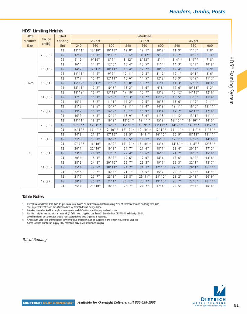
Available for Overnight Delivery, call 866-638-1908
Headers, Jambs, PostsH
DS
®Fram
ing System
81
HDS Stud WindloadMember Gauge Spacing 25 psf 30 psf 35 psf
Size (mils) (in) 240 360 600 240 360 600 240 360 60012 13' 11'' 12' 10'' 10' 10'' 12' 8'' 12' 1'' 10' 2'' 11' 9'' 11' 6'' 9' 8''
20 (33) 16 12' 0'' 11' 8'' 9' 10'' 10' 12'' 10' 12'' 9' 3'' 10' 2'' 10' 2'' 8' 10'' 24 9' 10'' 9' 10'' 8' 7'' 8' 12'' 8' 12'' 8' 1'' 8' 4'' * 8' 4'' * 7' 8'' 12 16' 4'' 14' 3'' 12' 0'' 15' 4'' 13' 5'' 11' 4'' 14' 3'' 12' 9'' 10' 9''
18 (43) 16 14' 7'' 12' 11'' 10' 11'' 13' 4'' 12' 2'' 10' 3'' 12' 4'' 11' 7'' 9' 9'' 24 11' 11'' 11' 4'' 9' 7'' 10' 11'' 10' 8'' 8' 12'' 10' 1'' 10' 1'' 8' 6'' 12 17' 7'' 15' 4'' 12' 11'' 16' 6'' 14' 5'' 12' 2'' 15' 9'' 13' 9'' 11' 7''
3.625 16 (54) 16 15' 12'' 13' 11'' 11' 9'' 15' 0'' 13' 2'' 11' 1'' 14' 3'' 12' 6'' 10' 6'' 24 13' 11'' 12' 2'' 10' 3'' 13' 2'' 11' 6'' 9' 8'' 12' 6'' 10' 11'' 9' 2'' 12 18' 12'' 16' 7'' 13' 12'' 17' 10'' 15' 7'' 13' 2'' 16' 12'' 14' 10'' 12' 6''
14 (68) 16 17' 3'' 15' 1'' 12' 9'' 16' 3'' 14' 2'' 11' 12'' 15' 5'' 13' 6'' 11' 4'' 24 15' 1'' 13' 2'' 11' 1'' 14' 2'' 12' 5'' 10' 5'' 13' 6'' 11' 9'' 9' 11'' 12 21' 2'' 18' 6'' 15' 7'' 19' 11'' 17' 4'' 14' 8'' 18' 11'' 16' 6'' 13' 11''
12 (97) 16 19' 2'' 16' 9'' 14' 2'' 18' 1'' 15' 9'' 13' 4'' 17' 2'' 14' 12'' 12' 8'' 24 16' 9'' 14' 8'' 12' 4'' 15' 9'' 13' 9'' 11' 8'' 14' 12'' 13' 1'' 11' 1'' 12 19' 11'' 19' 2'' 16' 2'' 18' 2'' * 18' 1'' * 15' 3'' 16' 10'' * 16' 10'' * 14' 5''
20 (33) 16 17' 3'' * 17' 3'' * 14' 8'' 15' 9'' * 15' 9'' * 13' 10'' * 14' 7'' * 14' 7'' * 13' 2'' *24 14' 1'' * 14' 1'' * 12' 10'' * 12' 10'' * 12' 10'' * 12' 1'' * 11' 11'' * 11' 11'' * 11' 6'' *12 24' 3'' 21' 2'' 17' 10'' 22' 5'' 19' 11'' 16' 10'' 20' 9'' 18' 11'' 15' 11''
18 (43) 16 21' 3'' 19' 3'' 16' 3'' 19' 5'' 18' 1'' 15' 3'' 17' 11'' 17' 2'' 14' 6'' 24 17' 4'' * 16' 10'' 14' 2'' 15' 10'' * 15' 10'' * 13' 4'' 14' 8'' * 14' 8'' * 12' 8'' *12 26' 1'' 22' 10'' 19' 3'' 24' 7'' 21' 6'' 18' 1'' 23' 4'' 20' 5'' 17' 2''
6 16 (54) 16 23' 9'' 20' 9'' 17' 6'' 22' 4'' 19' 6'' 16' 5'' 21' 2'' 18' 6'' 15' 8'' 24 20' 9'' 18' 1'' 15' 3'' 19' 6'' 17' 0'' 14' 4'' 18' 6'' 16' 2'' 13' 8'' 12 28' 3'' 24' 8'' 20' 10'' 26' 7'' 23' 3'' 19' 7'' 25' 3'' 22' 1'' 18' 7''
14 (68) 16 25' 8'' 22' 5'' 18' 11'' 24' 2'' 21' 1'' 17' 10'' 22' 11'' 20' 1'' 16' 11'' 24 22' 5'' 19' 7'' 16' 6'' 21' 1'' 18' 5'' 15' 7'' 20' 1'' 17' 6'' 14' 9'' 12 31' 7'' 27' 7'' 23' 3'' 29' 8'' 25' 11'' 21' 10'' 28' 2'' 24' 8'' 20' 9''
12 (97) 16 28' 8'' 25' 0'' 21' 1'' 26' 12'' 23' 7'' 19' 10'' 25' 7'' 22' 5'' 18' 11'' 24 25' 0'' 21' 10'' 18' 5'' 23' 7'' 20' 7'' 17' 4'' 22' 5'' 19' 7'' 16' 6''
HDS® Limiting Heights
Table Notes
1) Except for wind loads less than 15 psf, values are based on deflection calculations using 70% of components and cladding wind load. This is per IBC 2002 and the AISI Standard for CFS Wall Stud Design 2004.
2) Members are checked for simple span moment and deflection at mid-span, and end shear.3) Limiting heights marked with an asterisk (*) fail in web crippling per the AISI Standard for CFS Wall Stud Design 2004.
A web stiffener or connection that is not susceptible to web crippling is required.4) Check with your local Dietrich plant to verify if HDS members can be supplied in the length required for your job.
Some Dietrich plants can supply HDS members only in 20' maximum lengths.
Patent Pending
07856 DMF Catalog 40-81.qxd:Pgs 40-81 6/24/10 3:27 PM Page 81
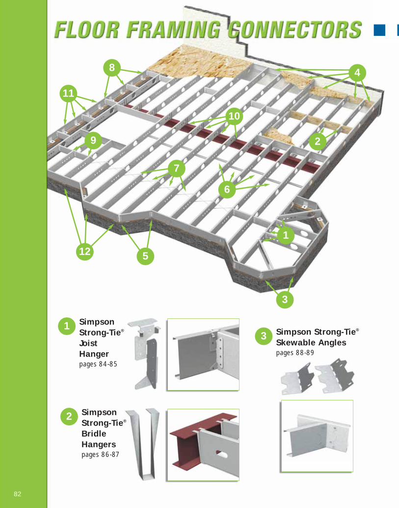
1 SimpsonStrong-Tie®
Joist Hangerpages 84-85
12
10
2 SimpsonStrong-Tie®
BridleHangerspages 86-87
3 Simpson Strong-Tie®
Skewable Anglespages 88-89
82
1
2
3
4
5
6
7
9
11
8
07856 DMF Catalog 82-105.qxd:Pgs 82-105 6/24/10 3:15 PM Page 82

5 Field SkewableRim TrackSplice Platepages 92-93
6 TradeReady®
StructuralBlockingpages 94-95
7 SimpsonStrong-Tie®
TensionBracingpages 96-97
8 EasyClip™ E-Series™ Clip Anglespages 98-99
9 EasyClip™
S-Series™
Clip Anglespages 100-101
10 Quick Twist™
WebStiffenerpages 102-103
11 FoundationClipspage 104
12 SimpsonStrong-Tie®
Lateral Tie Platepage 105
4 Simpson Strong-Tie® LedgerConnector pages 90-91
83
07856 DMF Catalog 82-105.qxd:Pgs 82-105 6/24/10 3:15 PM Page 83
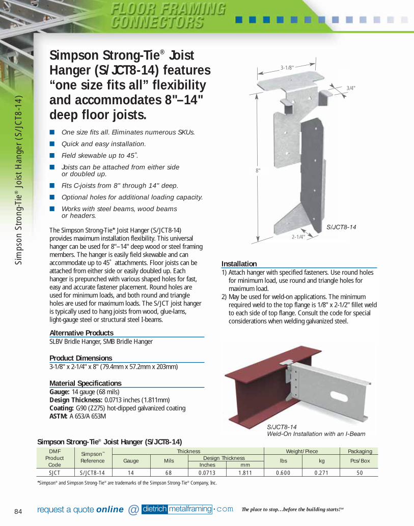
84 dietrich metalframing •com The place to stop…before the building starts! SMrequest a quote online @
■ One size fits all. Eliminates numerous SKUs.
■ Quick and easy installation.
■ Field skewable up to 45˚.
■ Joists can be attached from either side or doubled up.
■ Fits C-joists from 8" through 14" deep.
■ Optional holes for additional loading capacity.
■ Works with steel beams, wood beamsor headers.
The Simpson Strong-Tie* Joist Hanger (S/ JCT8-14)provides maximum installation flexibility. This universalhanger can be used for 8"–14" deep wood or steel framingmembers. The hanger is easily field skewable and canaccommodate up to 45˚ attachments. Floor joists can beattached from either side or easily doubled up. Eachhanger is prepunched with various shaped holes for fast,easy and accurate fastener placement. Round holes areused for minimum loads, and both round and triangleholes are used for maximum loads. The S/ JCT joist hangeris typically used to hang joists from wood, glue-lams, light-gauge steel or structural steel I-beams.
Alternative ProductsSLBV Bridle Hanger, SMB Bridle Hanger
Product Dimensions3-1/8" x 2-1/4" x 8" (79.4mm x 57.2mm x 203mm)
Material SpecificationsGauge: 14 gauge (68 mils)Design Thickness: 0.0713 inches (1.811mm)Coating: G90 (Z275) hot-dipped galvanized coatingASTM: A 653/A 653M
Simpson Strong-Tie® JoistHanger (S/JCT8-14) features“one size fits all” flexibilityand accommodates 8"–14"deep floor joists.
Installation1) Attach hanger with specified fasteners. Use round holes
for minimum load, use round and triangle holes formaximum load.
2) May be used for weld-on applications. The minimumrequired weld to the top flange is 1/8" x 2-1/2" fillet weldto each side of top flange. Consult the code for specialconsiderations when welding galvanized steel.
DMF Simpson™ Thickness Weight/Piece PackagingProduct Reference Gauge Mils Design Thickness lbs kg Pcs/BoxCode Inches mmSJCT S/JCT8-14 14 68 0.0713 1.811 0.600 0.271 50
Simpson Strong-Tie® Joist Hanger (S/JCT8-14)
S/JCT8-14
S/JCT8-14Weld-On Installation with an I-Beam
8"
3-1/8"
3/4"
2-1/4"
*Simpson® and Simpson Strong-Tie® are trademarks of the Simpson Strong-Tie® Company, Inc.
Sim
pson
Stro
ng-T
ie®
Jois
t Han
ger
(S/J
CT8
-14)
07856 DMF Catalog 82-105.qxd:Pgs 82-105 6/24/10 3:16 PM Page 84
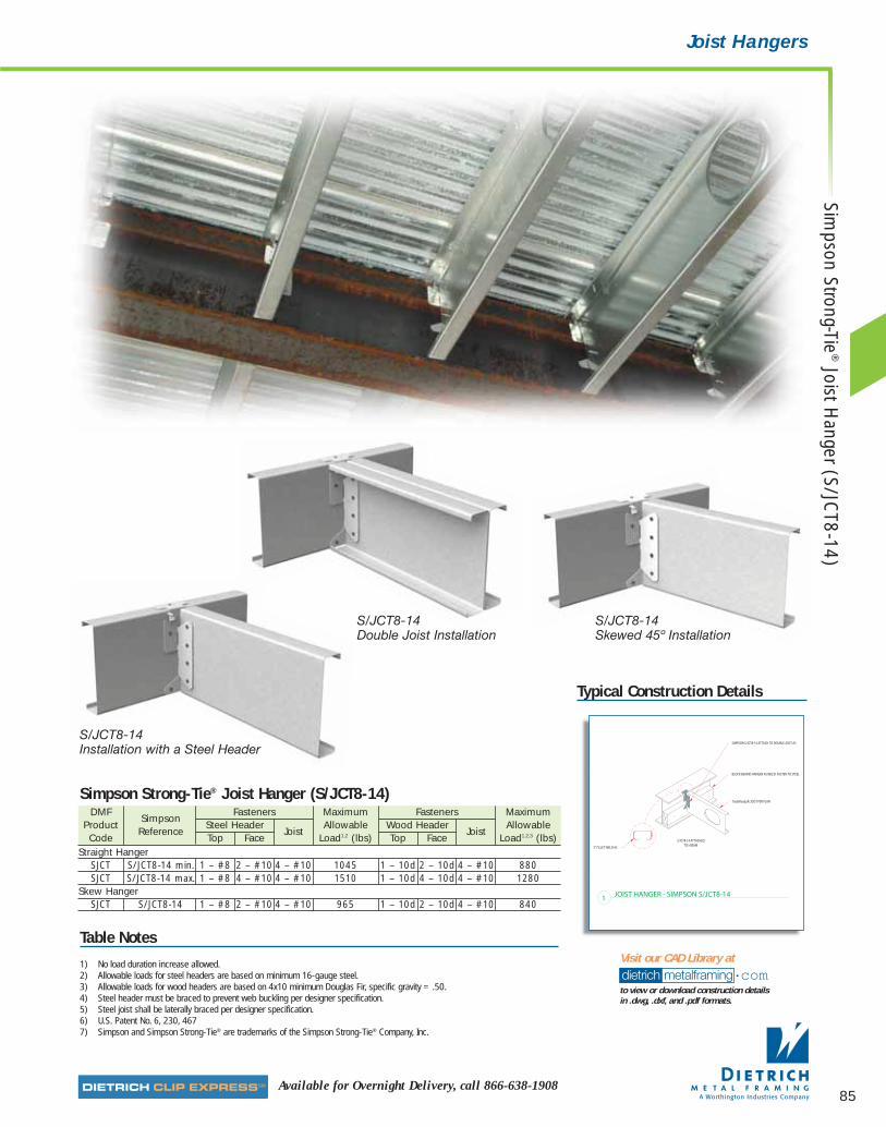
85Available for Overnight Delivery, call 866-638-1908
Joist Hangers
Typical Construction Details
DMF Simpson
Fasteners Maximum Fasteners Maximum Product
ReferenceSteel Header
JoistAllowable Wood Header
JoistAllowable
Code Top Face Load1,2 (lbs) Top Face Load1,2,3 (lbs)Straight Hanger
SJCT S/JCT8-14 min. 1 – #8 2 – #10 4 – #10 1045 1 – 10d 2 – 10d 4 – #10 880SJCT S/JCT8-14 max. 1 – #8 4 – #10 4 – #10 1510 1 – 10d 4 – 10d 4 – #10 1280
Skew HangerSJCT S/JCT8-14 1 – #8 2 – #10 4 – #10 965 1 – 10d 2 – 10d 4 – #10 840
Simpson Strong-Tie® Joist Hanger (S/JCT8-14)
Table Notes
1) No load duration increase allowed.2) Allowable loads for steel headers are based on minimum 16-gauge steel.3) Allowable loads for wood headers are based on 4x10 minimum Douglas Fir, specific gravity = .50.4) Steel header must be braced to prevent web buckling per designer specification.5) Steel joist shall be laterally braced per designer specification.6) U.S. Patent No. 6, 230, 4677) Simpson and Simpson Strong-Tie® are trademarks of the Simpson Strong-Tie® Company, Inc.
dietrich metalframing •comto view or download construction details in .dwg, .dxf, and .pdf formats.
Visit our CAD Library at
S/JCT8-14Installation with a Steel Header
S/JCT8-14Skewed 45º Installation
S/JCT8-14Double Joist Installation
Simpson Strong-Tie
®Joist H
anger (S/JCT8-14)
07856 DMF Catalog 82-105.qxd:Pgs 82-105 6/24/10 3:16 PM Page 85
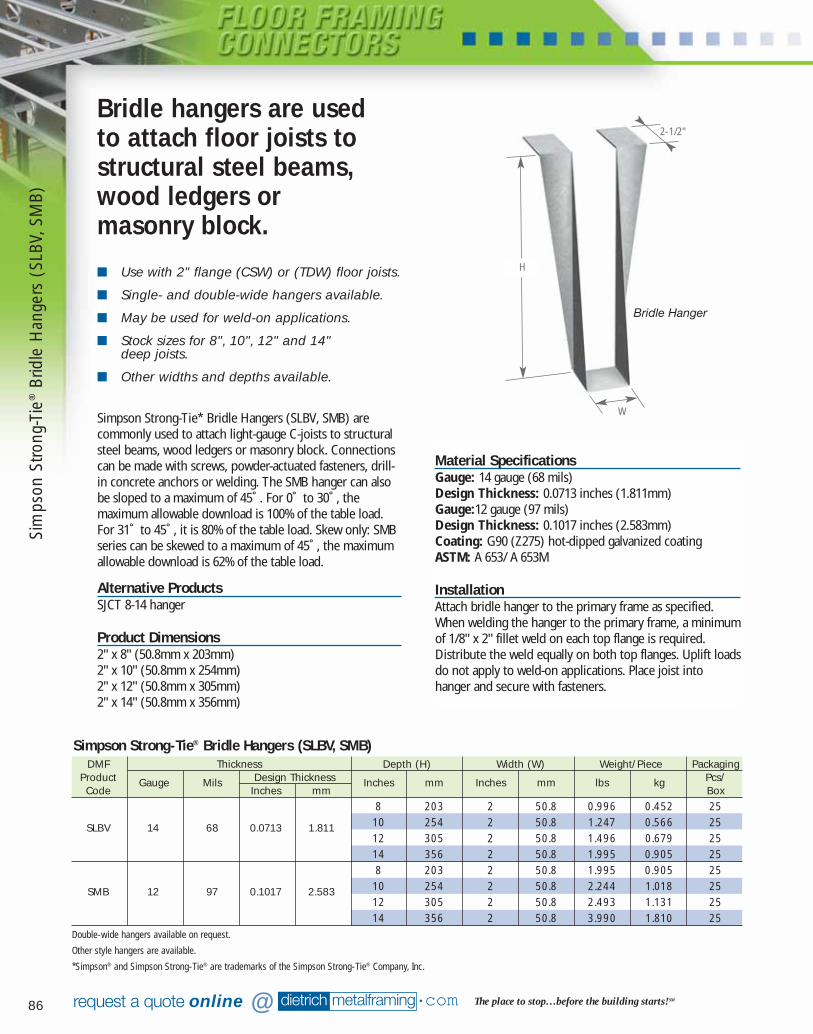
86 dietrich metalframing •com The place to stop…before the building starts! SMrequest a quote online @
■ Use with 2" flange (CSW) or (TDW) floor joists.
■ Single- and double-wide hangers available.
■ May be used for weld-on applications.
■ Stock sizes for 8", 10", 12" and 14" deep joists.
■ Other widths and depths available.
Simpson Strong-Tie* Bridle Hangers (SLBV, SMB) arecommonly used to attach light-gauge C-joists to structuralsteel beams, wood ledgers or masonry block. Connectionscan be made with screws, powder-actuated fasteners, drill-in concrete anchors or welding. The SMB hanger can alsobe sloped to a maximum of 45˚. For 0˚ to 30˚, themaximum allowable download is 100% of the table load.For 31˚ to 45˚, it is 80% of the table load. Skew only: SMBseries can be skewed to a maximum of 45˚, the maximumallowable download is 62% of the table load.
Alternative ProductsSJCT 8-14 hanger
Product Dimensions2" x 8" (50.8mm x 203mm)2" x 10" (50.8mm x 254mm)2" x 12" (50.8mm x 305mm)2" x 14" (50.8mm x 356mm)
Bridle hangers are used to attach floor joists tostructural steel beams,wood ledgers or masonry block.
Material SpecificationsGauge: 14 gauge (68 mils) Design Thickness: 0.0713 inches (1.811mm)Gauge:12 gauge (97 mils)Design Thickness: 0.1017 inches (2.583mm)Coating: G90 (Z275) hot-dipped galvanized coatingASTM: A 653/ A 653M
InstallationAttach bridle hanger to the primary frame as specified.When welding the hanger to the primary frame, a minimumof 1/8" x 2" fillet weld on each top flange is required.Distribute the weld equally on both top flanges. Uplift loadsdo not apply to weld-on applications. Place joist intohanger and secure with fasteners.
DMF Thickness Depth (H) Width (W) Weight/Piece PackagingProduct Gauge Mils Design Thickness Inches mm Inches mm lbs kg Pcs/Code Inches mm Box
8 203 2 50.8 0.996 0.452 25
SLBV 14 68 0.0713 1.811 10 254 2 50.8 1.247 0.566 2512 305 2 50.8 1.496 0.679 2514 356 2 50.8 1.995 0.905 258 203 2 50.8 1.995 0.905 25
SMB 12 97 0.1017 2.583 10 254 2 50.8 2.244 1.018 2512 305 2 50.8 2.493 1.131 2514 356 2 50.8 3.990 1.810 25
Double-wide hangers available on request.
Other style hangers are available.
*Simpson® and Simpson Strong-Tie® are trademarks of the Simpson Strong-Tie® Company, Inc.
Simpson Strong-Tie® Bridle Hangers (SLBV, SMB)
Bridle Hanger
H
2-1/2"
W
Sim
pson
Stro
ng-T
ie®
Brid
le H
ange
rs (
SLBV
, SM
B)
07856 DMF Catalog 82-105.qxd:Pgs 82-105 6/24/10 3:16 PM Page 86
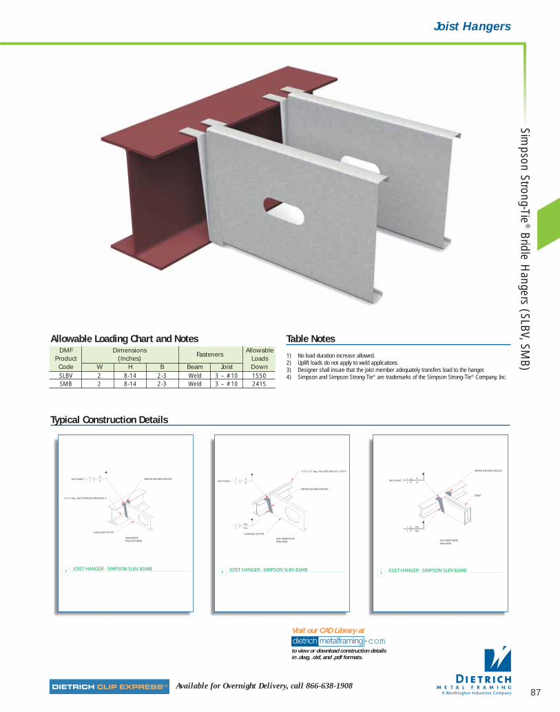
87Available for Overnight Delivery, call 866-638-1908
Joist Hangers
Typical Construction Details
dietrich metalframing •comto view or download construction details in .dwg, .dxf, and .pdf formats.
Visit our CAD Library at
Table Notes
1) No load duration increase allowed.2) Uplift loads do not apply to weld applications.3) Designer shall insure that the joist member adequately transfers load to the hanger.4) Simpson and Simpson Strong-Tie® are trademarks of the Simpson Strong-Tie® Company, Inc.
DMF DimensionsFasteners
AllowableProduct (Inches) LoadsCode W H B Beam Joist DownSLBV 2 8-14 2-3 Weld 3 – #10 1550SMB 2 8-14 2-3 Weld 3 – #10 2415
Allowable Loading Chart and Notes
Simpson Strong-Tie
®Bridle H
angers (SLBV, SMB)
07856 DMF Catalog 82-105.qxd:Pgs 82-105 6/24/10 3:16 PM Page 87

88 dietrich metalframing •com The place to stop…before the building starts! SMrequest a quote online @
■ Adjustable from 0˚ to 135˚.
■ Bend one time only.
■ Available in 18 gauge.
■ IBOC ER 5275 Recognized.
Simpson Strong-Tie* Skewable Angles (SLS5, SLS7) areused to make rigid attachments of joist-to- joist, roof rafterto hip beam or joist-to-other-miscellaneous framing. Thisclip is ideal for making off-angle connections. The skewableclip is shipped at 45˚ and can easily be field-bent from 0 to135˚.
CAUTION: This clip can only be bent one time.
Alternative ProductsTradeReady® Splice Plate
Product Dimensions2" x 2" x 4-7/8" (50.8mm x 50.8mm x 124mm)2" x 2" x 6-3/8" (50.8mm x 50.8mm x 162mm)
Material SpecificationsGauge: 18 gauge (43 mils)Design Thickness: 0.0451 inches (1.146mm)Coating: G90 (Z275) hot-dipped galvanized coatingASTM: A 653/A 653M
InstallationUse all specified fasteners. S/LS—field-skewable; bend onetime only. Joist must be constrained against rotation whenusing a single S/LS per connection.
Simpson Strong-Tie* Skewable utility clip usedfor rigid and off-angle attachments of joist to joists, roof rafter to hip beam or other off-angle connections.
*Simpson® and Simpson Strong-Tie® are trademarks of the Simpson Strong-Tie® Company, Inc.
DMF Thickness Size Weight/Piece PackagingProduct Gauge Mils Design Thickness Inches mm lbs kg Pcs/Code Inches mm BoxSLS5 18 43 0.0451 1.146 4-7/8 124 0.300 0.136 100SLS7 18 43 0.0451 1.146 6-3/8 162 0.400 0.181 50
Simpson Strong-Tie® Skewable Angles (SLS5, SLS7)
SLS5
SLS7
6-3/8"
2"2"
4-7/8"
2"
2"
Sim
pson
Stro
ng-T
ie®
Skew
able
Ang
les
(SLS
5, S
LS7)
07856 DMF Catalog 82-105.qxd:Pgs 82-105 6/24/10 3:16 PM Page 88

89Available for Overnight Delivery, call 866-638-1908
Joist Hangers
Table Notes
1) No load duration increase allowed.2) Loads are for one part only.3) Joist must be restrained against rotation.4) Simpson® and Simpson Strong-Tie® are trademarks of the Simpson Strong-Tie® Company, Inc.
Typical Construction Details
DMFSimpson Length Allowable Loads
ProductReference
FastenersCode Inches mm F1 F2SLS5 S/LS50 4-7/8 124 4 – #10 500 –SLS7 S/LS70 6-3/8 162 6 – #10 760 –
Simpson® (SLS5, SLS7)Reinforcing and Skewable Angles
dietrich metalframing •comto view or download construction details in .dwg, .dxf, and .pdf formats.
Visit our CAD Library at
Simpson Strong-Tie
®Skew
able Angles (SLS5, SLS7)
07856 DMF Catalog 82-105.qxd:Pgs 82-105 6/24/10 3:16 PM Page 89

90 dietrich metalframing •com The place to stop…before the building starts! SMrequest a quote online @
■ Cost-effective connector used in ICF construction.
■ Easy, quick and versatile.
■ Anchors securely within the concrete.
■ Maximum allowable load for ICFL is 2235 lbs.(1011 kg).
The Simpson Strong-Tie* Ledger Connector (ICFL) isengineered to solve the challenges of mounting steel orwood ledgers to insulated concrete form (ICF) walls.Simpson’s Ledger Connector System is easy, quick andversatile to use. The perforations in the embedded leg ofthe ICFL permit the concrete to flow around it, anchoringthe ICFL securely within the concrete. The exposed flangeprovides a structural surface for mounting either a wood or steel ledger.
Product Dimensions5-15/16" x 2-1/4" x 10-3/8" (151mm x 57.2mm x 264mm)
Material SpecificationsGauge: 14 gauge (68 mils)Design Thickness: 0.0713 inches(1.811mm)Coating: G90 (Z275) hot-dipped galvanized coatingASTM: A 653/A 653M
InstallationSnap chalk line for bottom of ledger. Mark required oncenter spacing. Cut vertical kerfs at marks. Insert ICFL.Pour concrete. For Steel Ledger: Position steel ledgeragainst ICFL. Attach with three 1/4 –14 x 3/4" #3 drill pt.screws (not provided). Minimum screw shear capacity is750 lbs. Maximum foam plastic insulation thickness of theICF face board is 2-5/8" (66.7mm).
The Simpson Strong-Tie® Ledger Connector (ICFL) provides a quick, easyand versatile method for attaching steelrim joists to insulated concrete forms.
*Simpson® and Simpson Strong-Tie® are trademarks of the Simpson Strong-Tie® Company, Inc.
DMF Simpson™ Thickness Weight/Piece PackagingProduct Reference Gauge Mils Design Thickness lbs kg Pcs/Code Inches mm BoxICFL ICFLC 14 68 0.0713 1.811 1.810 0.820 20
Simpson Strong-Tie® Ledger Connector (ICFL)
Ledger Connector
2-1/4"5-15/16"
10-3/8"
Sim
pson
Stro
ng-T
ie®
Ledg
er C
onne
ctor
(IC
FL)
07856 DMF Catalog 82-105.qxd:Pgs 82-105 6/24/10 3:16 PM Page 90
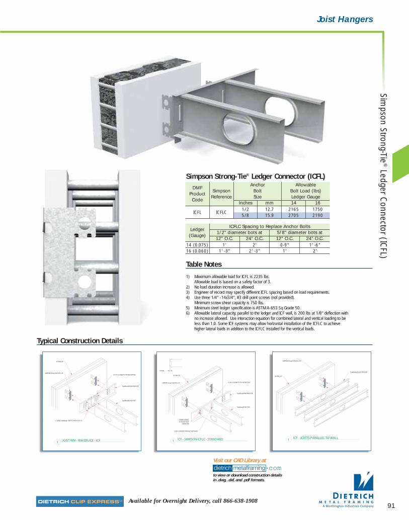
91Available for Overnight Delivery, call 866-638-1908
Joist Hangers
Typical Construction Details
dietrich metalframing •comto view or download construction details in .dwg, .dxf, and .pdf formats.
Visit our CAD Library at
Table Notes
1) Maximum allowable load for ICFL is 2235 lbs.Allowable load is based on a safety factor of 3.
2) No load duration increase is allowed.3) Engineer of record may specify different ICFL spacing based on load requirements.4) Use three 1/4" -14x3/4", #3 drill point screws (not provided).
Minimum screw shear capacity is 750 lbs.5) Minimum steel ledger specification is ASTM A-653 Sq Grade 50.6) Allowable lateral capacity, parallel to the ledger and ICF wall, is 200 lbs at 1/8" deflection with
no increase allowed. Use interaction equation for combined lateral and veritcal loading to beless than 1.0. Some ICF systems may allow horizontal installation of the ICFLC to achievehigher lateral loads in addition to the ICFLC installed for the vertical loads.
DMF Anchor Allowable
Product Simpson Bolt Bolt Load (lbs)
CodeReference Size Ledger Gauge
Inches mm 14 16
ICFL ICFLC1/2 12.7 2165 17505/8 15.9 2705 2190
Simpson Strong-Tie® Ledger Connector (ICFL)
LedgerICFLC Spacing to Replace Anchor Bolts
(Gauge)1/2" diameter bots at 5/8" diameter bots at12" O.C. 24" O.C. 12" O.C. 24" O.C.
14 (0.075) 1' 2' 0-9" 1' -6"16 (0.060) 1' -3" 2' -3" 1' 2'
Simpson Strong-Tie
®Ledger C
onnector (ICFL)
07856 DMF Catalog 82-105.qxd:Pgs 82-105 6/24/10 3:16 PM Page 91

92 dietrich metalframing •com The place to stop…before the building starts! SMrequest a quote online @
Fiel
d Sk
ewab
le T
rade
Read
y®Ri
m T
rack
Spl
ice
Plat
e (T
DSP
)
■ Field skewable from 0º to 135º.
■ Ideal for bay and bow windows.
■ Great for off-angle connections.
■ Prepunched for easy installation.
The Dietrich Field Skewable TradeReady® Rim Track SplicePlate provides an easy and efficient method for splicingTradeReady® Rim. This plate is also ideal for connectingand reinforcing the rim at bay or bow window details. Thecenter of the plate allows for easy one-time field bendingfrom 0˚ to 135˚.
CAUTION: This plate can only be bent one time.
Alternative ProductsSimpson Strong-Tie® Skewable Angles (SLS5, SLS7)
Product Dimensions4" x 6" (102mm x 152mm) (Can be bent to 2" x 2" x 6")
Material SpecificationsGauge: 18 gauge (43 mils)Design Thickness: 0.0451 inches (1.140mm)Yield Strength: Mill-Certified SS Grade 33 ksi (230 MPa)Gauge: 16 gauge (54 mils)Design Thickness: 0.0566 inches (1.438mm)Coating: G90 (Z275) hot-dipped galvanized coatingYield Strength: Mill-Certified SS Grade 50 ksi (340 MPa)ASTM: A 653/A 653M
InstallationFor splicing connections, align center slots in splice plateover the joint of the rim joists. Secure splice plate by fillingall prepunched screw holes with #10 screws.
For off-angle connections, field bend (ONE TIME ONLY ) tothe required degree so the plate fits securely over the twoadjoining members. Secure field skewable plate by filling allprepunched screw hole with #10 screws.
The Field Skewable TradeReady® Rim Track Splice Plateis ideal for splicing rim joist and is easily field skewable for off-angle rim joist connections.
DMF Thickness Size Weight/Piece PackagingProduct Gauge Mils Design Thickness Inches mm lbs kg Pcs/Code Inches mm BoxTDSP 18 43 0.0451 1.140 4 x 6 102 x 152 0.310 0.141 100TDSP 16 54 0.0566 1.438 4 x 6 102 x 152 0.389 0.176 100
Field Skewable TradeReady® Rim Track Splice Plate (TDSP)
6"
4"
2"
07856 DMF Catalog 82-105.qxd:Pgs 82-105 6/24/10 3:16 PM Page 92
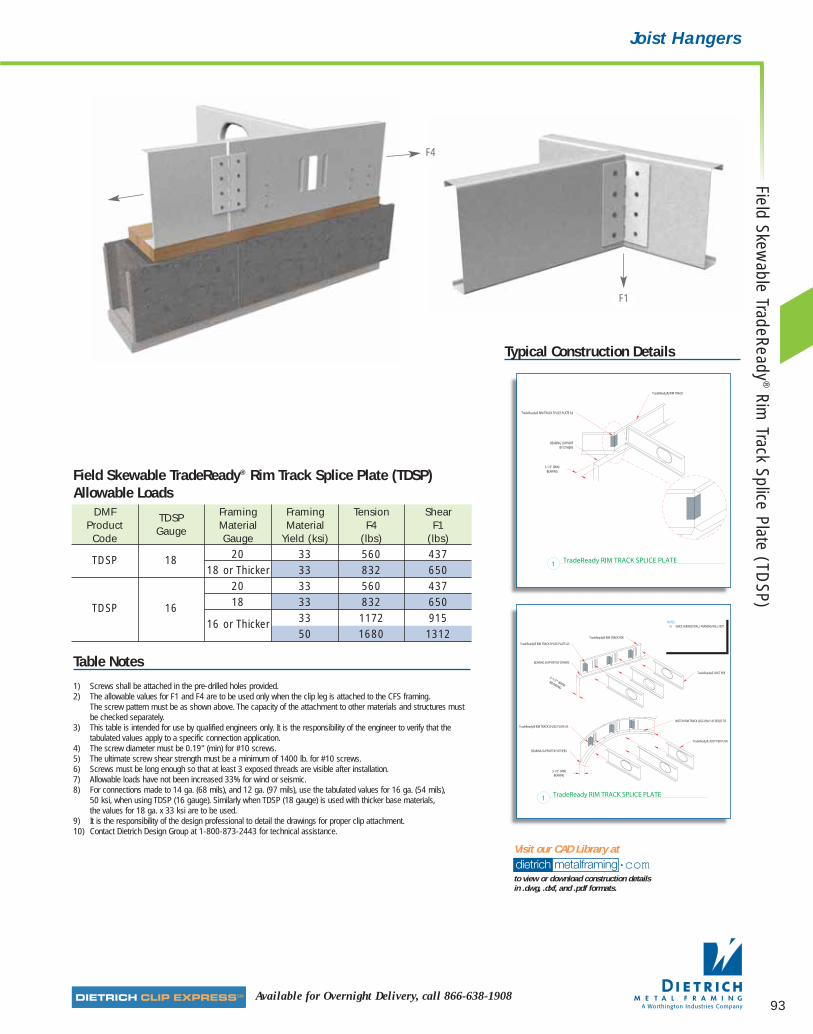
93Available for Overnight Delivery, call 866-638-1908
Joist HangersField Skew
able TradeReady®
Rim Track Splice Plate (TD
SP)
Typical Construction Details
dietrich metalframing •comto view or download construction details in .dwg, .dxf, and .pdf formats.
Visit our CAD Library at
DMF TDSP Framing Framing Tension ShearProduct Gauge Material Material F4 F1Code Gauge Yield (ksi) (lbs) (lbs)
TDSP 18 20 33 560 43718 or Thicker 33 832 650
20 33 560 437
TDSP 16 18 33 832 650
16 or Thicker 33 1172 91550 1680 1312
Field Skewable TradeReady® Rim Track Splice Plate (TDSP)Allowable Loads
Table Notes
1) Screws shall be attached in the pre-drilled holes provided.2) The allowable values for F1 and F4 are to be used only when the clip leg is attached to the CFS framing.
The screw pattern must be as shown above. The capacity of the attachment to other materials and structures mustbe checked separately.
3) This table is intended for use by qualified engineers only. It is the responsibility of the engineer to verify that thetabulated values apply to a specific connection application.
4) The screw diameter must be 0.19" (min) for #10 screws.5) The ultimate screw shear strength must be a minimum of 1400 lb. for #10 screws.6) Screws must be long enough so that at least 3 exposed threads are visible after installation.7) Allowable loads have not been increased 33% for wind or seismic.8) For connections made to 14 ga. (68 mils), and 12 ga. (97 mils), use the tabulated values for 16 ga. (54 mils),
50 ksi, when using TDSP (16 gauge). Similarly when TDSP (18 gauge) is used with thicker base materials, the values for 18 ga. x 33 ksi are to be used.
9) It is the responsibility of the design professional to detail the drawings for proper clip attachment.10) Contact Dietrich Design Group at 1-800-873-2443 for technical assistance.
F4
F1
07856 DMF Catalog 82-105.qxd:Pgs 82-105 6/24/10 3:16 PM Page 93
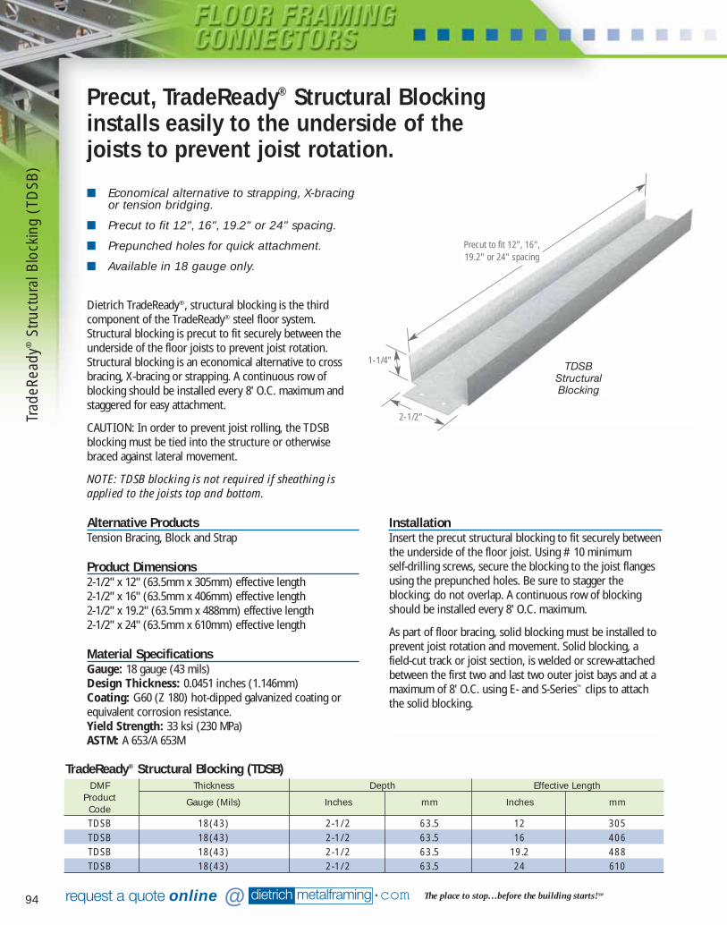
94 dietrich metalframing •com The place to stop…before the building starts! SMrequest a quote online @
■ Economical alternative to strapping, X-bracingor tension bridging.
■ Precut to fit 12", 16", 19.2" or 24" spacing.
■ Prepunched holes for quick attachment.
■ Available in 18 gauge only.
Dietrich TradeReady®‚ structural blocking is the thirdcomponent of the TradeReady® steel floor system.Structural blocking is precut to fit securely between theunderside of the floor joists to prevent joist rotation.Structural blocking is an economical alternative to crossbracing, X-bracing or strapping. A continuous row ofblocking should be installed every 8' O.C. maximum andstaggered for easy attachment.
CAUTION: In order to prevent joist rolling, the TDSBblocking must be tied into the structure or otherwisebraced against lateral movement.
NOTE: TDSB blocking is not required if sheathing isapplied to the joists top and bottom.
Alternative ProductsTension Bracing, Block and Strap
Product Dimensions2-1/2" x 12" (63.5mm x 305mm) effective length2-1/2" x 16" (63.5mm x 406mm) effective length2-1/2" x 19.2" (63.5mm x 488mm) effective length2-1/2" x 24" (63.5mm x 610mm) effective length
Material SpecificationsGauge: 18 gauge (43 mils)Design Thickness: 0.0451 inches (1.146mm)Coating: G60 (Z 180) hot-dipped galvanized coating orequivalent corrosion resistance.Yield Strength: 33 ksi (230 MPa)ASTM: A 653/A 653M
Precut, TradeReady® Structural Blockinginstalls easily to the underside of thejoists to prevent joist rotation.
InstallationInsert the precut structural blocking to fit securely betweenthe underside of the floor joist. Using #10 minimum self-drilling screws, secure the blocking to the joist flangesusing the prepunched holes. Be sure to stagger theblocking; do not overlap. A continuous row of blockingshould be installed every 8' O.C. maximum.
As part of floor bracing, solid blocking must be installed toprevent joist rotation and movement. Solid blocking, afield-cut track or joist section, is welded or screw-attachedbetween the first two and last two outer joist bays and at amaximum of 8' O.C. using E- and S-Series™ clips to attachthe solid blocking.
DMF Thickness Depth Effective LengthProduct Gauge (Mils) Inches mm Inches mmCodeTDSB 18(43) 2-1/2 63.5 12 305TDSB 18(43) 2-1/2 63.5 16 406TDSB 18(43) 2-1/2 63.5 19.2 488TDSB 18(43) 2-1/2 63.5 24 610
TradeReady® Structural Blocking (TDSB)
TDSBStructuralBlocking
Precut to fit 12", 16",19.2" or 24" spacing
2-1/2"
1-1/4"
Trad
eRea
dy®
Stru
ctur
al B
lock
ing
(TD
SB)
07856 DMF Catalog 82-105.qxd:Pgs 82-105 6/24/10 3:16 PM Page 94
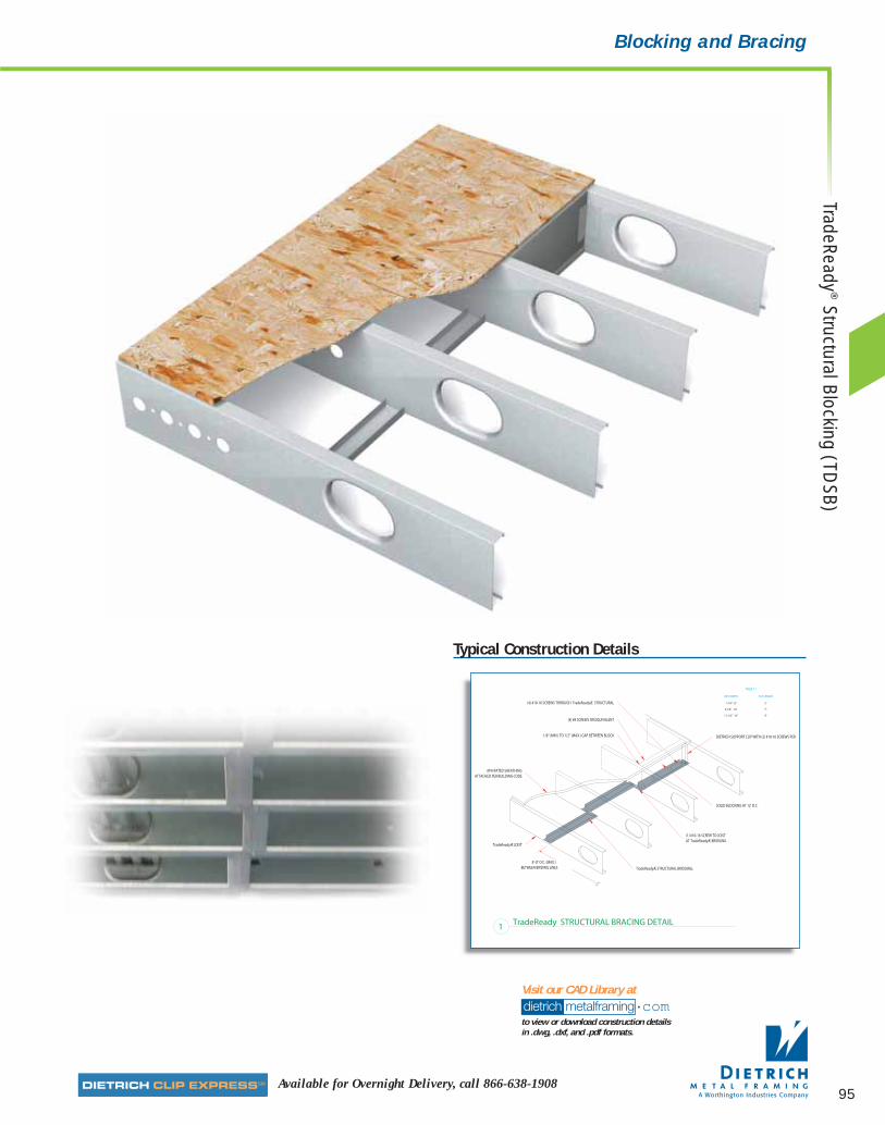
95Available for Overnight Delivery, call 866-638-1908
Blocking and Bracing
Typical Construction Details
dietrich metalframing •comto view or download construction details in .dwg, .dxf, and .pdf formats.
Visit our CAD Library at
TradeReady®
Structural Blocking (TDSB)
07856 DMF Catalog 82-105.qxd:Pgs 82-105 6/24/10 3:16 PM Page 95
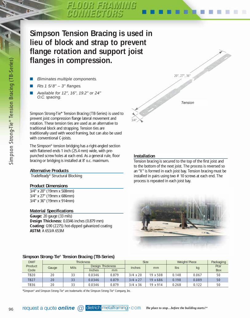
96 dietrich metalframing •com The place to stop…before the building starts! SMrequest a quote online @
■ Eliminates multiple components.
■ Fits 1 5/8" – 3" flanges.
■ Available for 12", 16", 19.2" or 24" O.C. spacing.
Simpson Tension Bracing is used inlieu of block and strap to preventflange rotation and support joistflanges in compression.
DMF Thickness Size Weight/Piece PackagingProduct Gauge Mils Design Thickness Inches mm lbs kg Pcs/Code Inches mm BoxTB20 20 33 0.0346 0.879 3/4 x 20 19 x 508 0.148 0.067 50TB27 20 33 0.0346 0.879 3/4 x 27 19 x 686 0.198 0.089 50TB36 20 33 0.0346 0.879 3/4 x 36 19 x 914 0.268 0.122 50
Simpson Strong-Tie® Tension Bracing (TB-Series)
Simpson Strong-Tie* Tension Bracing (TB-Series) is used toprevent joist compression flange lateral movement androtation. These tension ties are used as an alternative totraditional block and strapping. Tension ties aretraditionally used with wood framing, but can also be usedwith conventional C-joists.
The Simpson® tension bridging has a right-angled sectionwith flattened ends 1 inch (25.4 mm) wide, with pre-punched screw holes at each end. As a general rule, floorbracing or bridging is installed at 8' o.c. maximum.
Alternative ProductsTradeReady® Structural Blocking
Product Dimensions3/4" x 20" (19mm x 508mm)3/4" x 27" (19mm x 686mm)3/4" x 36" (19mm x 914mm)
Material SpecificationsGauge: 20 gauge (33 mils)Design Thickness: 0.0346 inches (0.879 mm)Coating: G90 (Z275) hot-dipped galvanized coatingASTM: A 653/A 653M
InstallationTension bracing is secured to the top of the first joist andto the bottom of the next joist. The process is reversed soan “X” is formed in each joist bay. Tension bracing must beinstalled in pairs using two #10 screws at each end. Theprocess is repeated in each joist bay.
Tension
20", 27", 36"
3/4"
*Simpson® and Simpson Strong-Tie® are trademarks of the Simpson Strong-Tie® Company, Inc.
Sim
pson
Stro
ng-T
ie®
Tens
ion
Brac
ing
(TB-
Serie
s)
07856 DMF Catalog 82-105.qxd:Pgs 82-105 6/24/10 3:16 PM Page 96
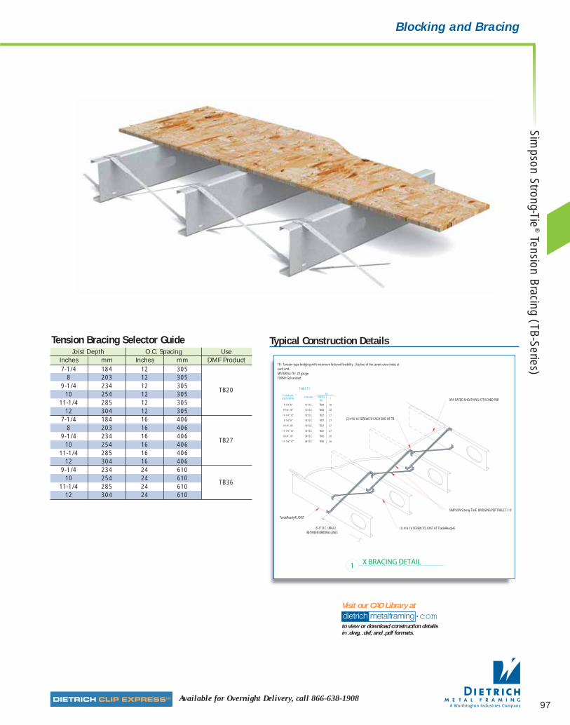
97Available for Overnight Delivery, call 866-638-1908
Blocking and Bracing
Joist Depth O.C. Spacing UseInches mm Inches mm DMF Product7-1/4 184 12 305
8 203 12 3059-1/4 234 12 305
TB2010 254 12 305
11-1/4 285 12 30512 304 12 305
7-1/4 184 16 4068 203 16 406
9-1/4 234 16 406TB27
10 254 16 40611-1/4 285 16 406
12 304 16 4069-1/4 234 24 610
10 254 24 610TB36
11-1/4 285 24 61012 304 24 610
Tension Bracing Selector Guide Typical Construction Details
dietrich metalframing •comto view or download construction details in .dwg, .dxf, and .pdf formats.
Visit our CAD Library at
Simpson Strong-Tie
®Tension Bracing (TB-Series)
07856 DMF Catalog 82-105.qxd:Pgs 82-105 6/24/10 3:16 PM Page 97

98 dietrich metalframing •com The place to stop…before the building starts! SMrequest a quote online @
■ 4" leg accommodates large standoff.
■ Lengths available in 3", 5", 7", 9" and 11".
■ Available in 16, 14 and 12 gauge.
■ Prepunched for faster and more accuratefastener attachment.
Dietrich EasyClip™ E-Series™ Clip Angles are used in avariety of floor framing applications including ladderblocking attachments, joist-to-joist connections and avariety of other rigid connections when a longer leg isrequired to secure framing members. This clip features a 4"wide leg to achieve rigid stand-off connections up to 3".This clip is frequently used with the S-Series™ clip to secureladder and solid blocking in floor framing assemblies. E-Series™ clips are prepunched for faster and more accuratefastener placement.
Alternative ProductsEasyClip™ D-Series™ Anchor Clip, Uni-Clip™
Product Dimensions4" x 1-1/2" x 3" (102mm x 38.0mm x 76.2mm)4" x 1-1/2" x 5" (102mm x 38.0mm x 127mm)4" x 1-1/2" x 7" (102mm x 38.0mm x 178mm)4" x 1-1/2" x 9" (102mm x 38.0mm x 229mm)4" x 1-1/2" x 11" (102mm x 38.0mm x 279mm)
Material SpecificationsGauge: 16 gauge (54 mils)Design Thickness: 0.0566 inches (1.438mm)Gauge: 14 gauge (68 mils)Design Thickness: 0.0713 inches (1.811mm)Gauge: 12 gauge (97 mils)Design Thickness: 0.1017 inches (2.583mm)Coating: G 90 (Z275) hot-dipped galvanized coatingYield Strength: Mill-certified SS Grade 50 ksi (340 MPa)ASTM: A 653/A 653M
This multipurpose clip features an extra long leg and is ideal for solid blocking,joist to joist and a variety ofother rigid framing applications.
EasyClip™ Support Clip(E-Series™)
3", 5", 7",9", 11"
4"
1-1/2"
InstallationSupport clips are attached to the cold-formed steel (CFS)framing members using #10 minimum self-drilling screwsdriven through the clip holes into the steel framing. Whennot filling all holes, install fasteners symmetrically startingat the top and bottom edges and move toward the centerof the clip. Clip can also be welded to the CFS framing.
F1
Easy
Clip
™E-
Serie
s™C
lip A
ngle
s
07856 DMF Catalog 82-105.qxd:Pgs 82-105 6/24/10 3:16 PM Page 98
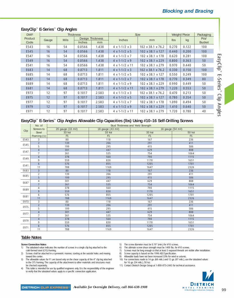
99Available for Overnight Delivery, call 866-638-1908
Blocking and Bracing
DMF Thickness Size Weight/Piece PackagingProduct Gauge Mils Design Thickness Inches mm lbs kg Pcs/Code Inches mm BucketE543 16 54 0.0566 1.438 4 x 1-1/2 x 3 102 x 38.1 x 76.2 0.270 0.122 100E545 16 54 0.0566 1.438 4 x 1-1/2 x 5 102 x 38.1 x 127 0.440 0.200 100E547 16 54 0.0566 1.438 4 x 1-1/2 x 7 102 x 38.1 x 178 0.620 0.281 100E549 16 54 0.0566 1.438 4 x 1-1/2 x 9 102 x 38.1 x 229 0.800 0.363 50E541 16 54 0.0566 1.438 4 x 1-1/2 x 11 102 x 38.1 x 279 0.970 0.440 50E683 14 68 0.0713 1.811 4 x 1-1/2 x 3 102 x 38.1 x 76.2 0.330 0.150 100E685 14 68 0.0713 1.811 4 x 1-1/2 x 5 102 x 38.1 x 127 0.550 0.249 100E687 14 68 0.0713 1.811 4 x 1-1/2 x 7 102 x 38.1 x 178 0.770 0.349 80E689 14 68 0.0713 1.811 4 x 1-1/2 x 9 102 x 38.1 x 229 0.990 0.449 50E681 14 68 0.0713 1.811 4 x 1-1/2 x 11 102 x 38.1 x 279 1.220 0.553 50E973 12 97 0.1017 2.583 4 x 1-1/2 x 3 102 x 38.1 x 76.2 0.470 0.213 50E975 12 97 0.1017 2.583 4 x 1-1/2 x 5 102 x 38.1 x 127 0.780 0.354 50E977 12 97 0.1017 2.583 4 x 1-1/2 x 7 102 x 38.1 x 178 1.090 0.494 50E979 12 97 0.1017 2.583 4 x 1-1/2 x 9 102 x 38.1 x 229 1.410 0.640 50E971 12 97 0.1017 2.583 4 x 1-1/2 x 11 102 x 38.1 x 279 1.720 0.780 40
EasyClip™ E-Series™ Clip Angles
No. of Stud Thickness and Yield Strength
ClipScrews to 20 gauge (33 mil) 18 gauge (43 mil) 16 gauge (54 mil)
Steel 33 ksi 33 ksi 33 ksi 50 ksiFraming (1) F1 F1 F1 F1
E543 3 80 118 167 236
E5452 139 206 291 4115 199 295 415 586
E5474 301 447 629 8887 361 535 754 1064
E5494 378 560 790 11159 559 830 1170 1651
E5416 576 855 1205 170111 788 1169 1647 2326
E683 3 80 118 167 236
E6852 139 206 291 4115 199 295 415 586
E6874 301 447 629 8887 361 535 754 1064
E6894 378 560 790 11159 559 830 1170 1651
E6816 576 855 1205 170111 788 1169 1647 2326
E973 3 80 118 167 236
E9752 139 206 291 4115 199 295 415 586
E9774 301 447 629 8887 361 535 754 1064
E9794 378 560 790 11159 559 830 1170 1651
E9716 576 855 1205 170111 788 1169 1647 2326
EasyClip™ E-Series™ Clip Angles Allowable Clip Capacities (lbs) Using #10–16 Self-Drilling Screws
Table Notes
Screw Connection Notes1) The tabulated value indicates the number of screws in a single clip leg attached to the
cold-formed steel (CFS) framing.2) Screws shall be attached in a symmetric manner, starting at the outside holes and moving
toward the center.3) The allowable values for F1 are based only on the shear capacity of the 4" clip leg attached
to the CFS framing. The capacity of the attachment to other materials and structures must be checked separately.
4) This table is intended for use by qualified engineers only. It is the responsibility of the engineerto verify that the tabulated values apply to a specific connection application.
5) The screw diameter must be 0.19" (min.) for #10 screws.6) The ultimate screw shear strength must be 1400 lbs. for #10 screws.7) Screws must be long enough so that at least 3 exposed threads are visible after installation.8) Screw capacity is based on the 1996 AISI Specification.9) Allowable loads have not been increased 33% for wind or seismic.10) For connections made to 14 ga. (68 mils.) and 12 ga. (97 mils.), use the tabulated values
for 16 ga. (54 mils.), 50 ksi.11) Contact Dietrich Design Group at 1-800-873-2443 for technical assistance.
EasyClip
™E-Series
™C
lip Angles
07856 DMF Catalog 82-105.qxd:Pgs 82-105 6/24/10 3:16 PM Page 99
100 dietrich metalframing •com The place to stop…before the building starts! SMrequest a quote online @
■ 1-1/2" x 1-1/2" legs.
■ Lengths available in 3", 5", 7", 9" and 11".
■ Prepunched for faster and more accuratefastener placement.
EasyClip™ S-Series™ ClipAngles are multipurposerigid connectors used in a variety of floor framingapplications.
EasyClip™ S-Series™ Clip Angles
1-1/2"
1-1/2"
3", 5", 7", 9", 11"
Dietrich EasyClip™ S-Series™ Clip Angles are used in avariety of floor framing applications including ladderblocking, solid blocking, joist-to-joist connections and avariety of other floor framing attachments. This clip iscommonly used with an E-Series™ clip to secure ladder andsolid blocking in floor framing assemblies. This high-performance multi-use utility clip is ideal for cornerreinforcements, stair openings and numerous supportapplications.
Alternative ProductsEasyClip™ X-Series ™ Clip Angle
Product Dimensions1-1/2" x 1-1/2" x 3" (38.1mm x 38.1mm x 76.2 mm)1-1/2" x 1-1/2" x 5" (38.1mm x 38.1mm x 127 mm)1-1/2" x 1-1/2" x 7" (38.1mm x 38.1mm x 178 mm)1-1/2" x 1-1/2" x 9" (38.1mm x 38.1mm x 229 mm)1-1/2" x 1-1/2" x 11" (38.1mm x 38.1mm x 279 mm)
Material SpecificationsGauge: 16 gauge (54 mils)Design Thickness: 0.0566 inches (1.438mm)Gauge: 14 gauge (68 mils)Design Thickness: 0.0713 inches (1.811mm)Gauge: 12 gauge (97 mils)Design Thickness: 0.1017 inches (2.583mm)Coating: G90 (Z275) hot-dipped galvanized coatingYield Strength: Mill-certified SS Grade 50 ksi (340 MPa)ASTM: A 653/A 653M
InstallationS-Series™ Clip Angles are attached to the cold-formed steel(CFS) framing members using #10 minimum self-drillingscrews driven through the clip holes into the steel framing.When not filling all holes, install fasteners symmetricallystarting at the top and bottom edges and move toward thecenter of the clip. Clip can also be welded to the CFSframing.
F1
Easy
Clip
™S-
Serie
s™C
lip A
ngle
s
07856 DMF Catalog 82-105.qxd:Pgs 82-105 6/24/10 3:16 PM Page 100

101Available for Overnight Delivery, call 866-638-1908
Blocking and Bracing
DMF Thickness Size Weight/Piece PackagingProduct Gauge Mils Design Thickness Inches mm lbs kg Pcs/Code Inches mm BucketS543 16 54 0.0566 1.438 1-1/2 x 1-1/2 x 3 38.1 x 38.1 x 76.2 0.140 0.064 400S545 16 54 0.0566 1.438 1-1/2 x 1-1/2 x 5 38.1 x 38.1 x 127 0.240 0.109 200S547 16 54 0.0566 1.438 1-1/2 x 1-1/2 x 7 38.1 x 38.1 x 178 0.340 0.154 100S549 16 54 0.0566 1.438 1-1/2 x 1-1/2 x 9 38.1 x 38.1 x 229 0.430 0.195 100S541 16 54 0.0566 1.438 1-1/2 x 1-1/2 x 11 38.1 x 38.1 x 279 0.530 0.240 100S683 14 68 0.0713 1.811 1-1/2 x 1-1/2 x 3 38.1 x 38.1 x 76.2 0.180 0.082 200S685 14 68 0.0713 1.811 1-1/2 x 1-1/2 x 5 38.1 x 38.1 x 127 0.300 0.136 200S687 14 68 0.0713 1.811 1-1/2 x 1-1/2 x 7 38.1 x 38.1 x 178 0.420 0.191 100S689 14 68 0.0713 1.811 1-1/2 x 1-1/2 x 9 38.1 x 38.1 x 229 0.540 0.245 100S681 14 68 0.0713 1.811 1-1/2 x 1-1/2 x 11 38.1 x 38.1 x 279 0.660 0.299 100S973 12 97 0.1017 2.583 1-1/2 x 1-1/2 x 3 38.1 x 38.1 x 76.2 0.260 0.118 200S975 12 97 0.1017 2.583 1-1/2 x 1-1/2 x 5 38.1 x 38.1 x 127 0.430 0.195 150S977 12 97 0.1017 2.583 1-1/2 x 1-1/2 x 7 38.1 x 38.1 x 178 0.600 0.272 100S979 12 97 0.1017 2.583 1-1/2 x 1-1/2 x 9 38.1 x 38.1 x 229 0.770 0.349 80S971 12 97 0.1017 2.583 1-1/2 x 1-1/2 x 11 38.1 x 38.1 x 279 0.940 0.426 70
EasyClip™ S-Series™ Clip Angles
No. of Stud Thickness and Yield StrengthScrews to 20 ga. (33 mil) 18 ga. (43 mil) 16 ga. (54 mil)
Clip Steel 33 ksi 33 ksi 50 ksiFraming (1) F1 F1 F1
S543 3 233 346 689
S5452 251 372 7405 515 765 1521
S5474 517 767 15267 815 1209 2405
S5494 538 798 15879 1115 1655 3293
S5416 803 1192 237211 1414 2097 4173
S683 3 233 346 689
S6852 251 372 7405 515 765 1521
S6874 517 767 15267 815 1209 2405
S6894 538 798 15879 1115 1655 3293
S6816 803 1192 237211 1414 2097 4173
S973 3 233 346 689
S9752 251 372 7405 515 765 1521
S9774 517 767 15267 815 1209 2405
S9794 538 798 15879 1115 1655 3293
S9716 803 1192 237211 1414 2097 4173
EasyClip™ S-Series™ Clip Angles Allowable Clip Capacities (lbs) Using #10–16 Self-Drilling Screws
Table Notes
Screw Connection Notes1) The tabulated value indicates the number of screws in a single clip leg attached to the cold-
formed steel (CFS) framing.2) Screws shall be attached in a symmetric manner, starting at the outside holes and working
toward the center.3) The allowable values for F1 are based only on the shear capacity of the clip leg attached to the
CFS framing. The capacity of the attachment to other materials and structures must bechecked separately.
4) This table is intended for use by qualified engineers only. It is the responsibility of the engineer to verify that the tabulated values apply to a specificconnection application.
5) The screw diameter must be 0.19" (min.) for #10 screws.
6) The ultimate screw shear strength must be 1400 lbs. for #10 screws.7) Screws must be long enough so that at least 3 exposed threads are visible after installation.8) Screw capacity is based on the 1996 AISI Specifiation.9) Allowable loads have not been increased 33% for wind or seismic.10) For connections made to 14 ga. (68 mils.) and 12 ga.
(97 mils.), use the tabulated values for 16 ga. (54 mils.), 50 ksi.11) It is the responsibility of the design professional to detail the drawings for proper clip
attachment.12) Contact Dietrich Design Group at 1-800-873-2443 for technical assistance.
EasyClip
™S-Series
™C
lip Angles
07856 DMF Catalog 82-105.qxd:Pgs 82-105 6/24/10 3:16 PM Page 101
102 dietrich metalframing •com The place to stop…before the building starts! SMrequest a quote online @
Qui
ckTw
ist™
Web
Stif
fene
r (W
S)
DMF Thickness Size* Weight/pcProduct Size
Gauge Mils Design Thickness Inches mm lbs kg PackagingCode (inches) Inches mm
7.25 184.2 1.190 0.5398.00 203.2 1.320 0.599 Packaged9.25 235.0 1.530 0.694 Dependent
QTWS 3-1/2 12 97 0.1017 2.583 10.00 254.0 1.660 0.753 On11.25 285.8 1.880 0.853 Order12.00 304.8 2.000 0.907 Quantity14.00 355.6 2.340 1.0617.25 184.2 1.690 0.7678.00 203.2 1.870 0.848 Packaged9.25 235.0 2.170 0.984 Dependent
QTWS 6 12 97 0.1017 2.583 10.00 254.0 2.350 1.066 On11.25 285.8 2.660 1.207 Order12.00 304.8 2.840 1.288 Quantity14.00 355.6 3.320 1.506
*Dimension is nominal size. Actual product is shorter to fit inside joist.
EasyClip™ Quick Twist Web Stiffeners provide excellent reinforcement at criticalload points to prevent web crippling.■ Simple, post installation assembly.
■ Easily rotated in-place for a tight fit.
■ Pre-punched for easy installation of fasteners.
■ Solid 12 gauge construction.
■ One-piece assembly.
QTWS
NEWITEM
EasyClip™ Quick Twist Web Stiffeners (QTWS) are used toprovide reinforcement of joist webs to prevent crippling.Web reinforcement is often required by design to enhancethe load capacity of joists. The unique design of QTWSallows the installer to insert the stiffener on the inside ofthe joist after the joist is installed. This stiffener eliminatesthe need to pre-insert traditional web stiffeners prior tojoist installation.
Material SpecificationsGauge: 12 gauge (97 mils)Design Thickness: 0.1017 inches (2.583 mm)Coating: G90 (Z275) hot-dipped galvanized coatingYield Strength: Mill-Certified SS Grade 50 ksi (340 MPa)ASTM: A 653/A 653M
1-1/4"
3-1/2" or 6"
7-1/4" to 14"
EasyClip™ Quick Twist Web Stiffener (QTWS)
InstallationThe unique design of the Dietrich web stiffener allows it tobe easily rotated in-place for a tight fit between flanges. Theweb stiffener shall be secured to the web of the joint with(3) #10-16 screws. Screws shall be driven through the top,bottom and middle pre-punched holes as shown in thefigures.
Patent Pending
07856 DMF Catalog 82-105.qxd:Pgs 82-105 6/24/10 3:16 PM Page 102

103Available for Overnight Delivery, call 866-638-1908
Web Stiffeners
OvernightDelivery!
Available for
Joist Joist Fy 3-1/2" Web Stiffener 6" Web StiffenerSize Gauge (ksi)(in) (mils) Cond.1 Cond.2 Cond.3 Cond.1 Cond.2 Cond.3
18(43) 33 5,360 5,781 5,659 5,932 6,403 6,265
16(54) 33 5,457 6,155 5,924 6,042 6,817 6,55850 5,574 6,632 6,282 6,177 7,351 6,959
7.25 14(68) 33 5,615 6,761 6,346 6,220 7,482 7,02150 5,813 7,550 6,921 6,447 8,359 7,660
12(97) 33 6,074 8,524 7,559 6,733 9,401 8,34050 6,509 10,222 8,759 7,224 11,267 9,659
18(43) 33 5,350 5,752 5,645 5,920 6,370 6,249
16(54) 33 5,443 6,116 5,905 6,027 6,773 6,53750 5,553 6,573 6,253 6,153 7,285 6,926
8 14(68) 33 5,596 6,708 6,320 6,200 7,424 6,99250 5,786 7,470 6,882 6,416 8,270 7,617
12(97) 33 6,045 8,438 7,516 6,700 9,307 8,29350 6,465 10,092 8,694 7,174 11,124 9,588
18(43) 33 5,334 5,707 5,623 5,902 6,320 6,224
16(54) 33 5,422 6,056 5,875 6,002 6,706 6,50350 5,521 6,481 6,208 6,116 7,182 6,876
9.25 14(68) 33 5,568 6,626 6,279 6,167 7,332 6,94750 5,742 7,345 6,820 6,366 8,132 7,548
12(97) 33 5,999 8,304 7,450 6,649 9,159 8,22050 6,396 9,888 8,594 7,096 10,900 9,477
16(54) 33 5,410 6,021 5,858 5,988 6,667 6,48450 5,503 6,429 6,182 6,095 7,124 6,847
10 14(68) 33 5,552 6,579 6,256 6,148 7,280 6,92250 5,718 7,275 6,785 6,338 8,053 7,510
12(97) 33 5,973 8,228 7,412 6,619 9,076 8,17950 6,356 9,773 8,537 7,052 10,773 9,415
16(54) 33 5,391 5,967 5,831 5,966 6,606 6,45450 5,474 6,347 6,141 6,062 7,032 6,802
11.25 14(68) 33 5,526 6,505 6,220 6,119 7,198 6,88150 5,679 7,163 6,730 6,294 7,929 7,448
12(97) 33 5,932 8,108 7,353 6,573 8,943 8,11450 6,294 9,590 8,447 6,981 10,573 9,316
16(54) 33 5,380 5,936 5,816 5,954 6,571 6,43750 5,457 6,300 6,118 6,043 6,979 6,775
12 14(68) 33 5,511 6,463 6,199 6,102 7,151 6,85850 5,657 7,099 6,699 6,268 7,858 7,413
12(97) 33 5,908 8,039 7,319 6,547 8,867 8,07650 6,258 9,486 8,395 6,941 10,458 9,259
14(68) 33 5,474 6,356 6,146 6,060 7,033 6,800
14 50 5,601 6,937 6,619 6,204 7,678 7,325
12(97) 33 5,849 7,865 7,233 6,480 8,677 7,98250 6,169 9,223 8,265 6,840 10,169 9,116
Allowable Web Crippling Loads (lbs)
Table Notes
1) The tabulated values indicate the total allowable web crippling capacities of a Dietrich Joist of thelisted size, stiffened with the Dietrich Quick Twist Web Stiffener.
2) The joist flanges must be fastened to the support at the bearing location.3) The 3 1/2" web stiffeners are to be used with bearing widths of 3-1/2”- 5-1/2” in the direction of the
joist. The 6" web stiffeners are to be used with bearing widths 6" and greater, in the direction of thejoist. A minimum-bearing dimension of 3” in the direction perpendicular to the joist is assumed.
4) Use (3) #10 screws to attach the Quick Twist Web Stiffener to the joist. Drive screws through the top,bottom, and middle pre-punched holes.
5) This table is intended for use by qualified engineers only. It is the responsibility of the engineer toverify that the Quick Twist Web Stiffener configuration and tabulated values apply to a specific webcrippling application.
6) Contact Dietrich Design Group at 1-800-873-2443 for technical assistance.
Condition 1
(3) #10-16 Screws,top, bottom, and midddle holes
Load
Load
Load
Condition 2
(3) #10-16 Screws,top, bottom, and midddle holes
Condition 3
(3) #10-16 Screws,top, bottom, and midddle holes
QuickTw
ist ™W
eb Stiffener (WS)
07856 DMF Catalog 82-105.qxd:Pgs 82-105 6/24/10 3:16 PM Page 103
104 dietrich metalframing •com The place to stop…before the building starts! SMrequest a quote online @
■ Prepunched for easy and accurate fastenerplacement.
■ Elongated slot provides for adjustableattachment to the foundation anchor bolts.
■ 16-gauge, G-90, 50 KSI steel.
Dietrich Foundation Clips (FDCL) are used to provide astrong, adjustable, rigid attachment of TradeReady® rimjoist or conventional structural track to the buildingfoundation. Foundation clips are secured to the foundationusing the elongated slots and anchor bolts. The elongatedslot provides a method to adjust the positioning of thefoundation clip, so it can fit securely against the rim even if the anchor bolts are not properly aligned. Theprepunched leg is screw attached to the face or web of thejoist. Clip spacing is based on loading requirements.
Product Dimensions5" x 5-1/2" x 5" (127mm x 140mm x 127mm)
Material SpecificationsGauge: 16 gauge (54 mils)Design Thickness: 0.0566 inches (1.438 mm)Coating: G90 (Z275) hot-dipped galvanized coatingYield Strength: Mill-Certified SS Grade 50 ksi (340 MPa)ASTM: A 653/A 653M
InstallationFor best results, foundation clips should be attachedadjacent to perpendicular joist members and spaced percode requirements or the engineer of records specification.Secure foundation clips to building foundation using SSTBanchor bolts or alternate anchorage calculated to resist thespecific load requirement.
Use steel nylon locking nuts and thread adhesive tominimize the chance of nut spin.
Secure foundation clip to rim track using #10 minimumself-drilling screws.
Foundation clips are used to secure TradeReady®
Rim Joist, structural track, end caps or parallel joists to the building foundation.
DMF Thickness Width Height Length Weight/Piece PackagingProduct Gauge Mils Design Thickness Inches mm Inches mm Inches mm lbs kg Pcs/Code Inches mm Box
FDCL 16 54 0.0566 1.438 5 127 5-1/2 140 5 127 0.900 0.407 80
Foundation Clips (FDCL)
Foundation Clip
5-1/2"
5"
5"
Foun
datio
n C
lips
(FD
CL)
07856 DMF Catalog 82-105.qxd:Pgs 82-105 6/24/10 3:16 PM Page 104

105Available for Overnight Delivery, call 866-638-1908
Foundation/Sill Plate Connectors
■ Prepunched holes for connection accuracy.
■ ICBO ER 5670 Recognized.
Table Notes
The LTP4 Lateral Tie Plate transfers shear forces from thejoist rim or blocking to the sill plate.
(1) 125% and 133% values are permitted to be used for roof and windor earthquake loading, respectively.
DMF Fasteners (qty-size)
Direction Allowable Loads1(lbf)
Product of Code Plates Joist Load (100) (125) (133)
6-8d x 1-1/2 6-8d x 1-1/2 G 515 645 685LTP4 6-8d x 1-1/2 6-8d x 1-1/2 J 515 645 685
6-8d x 1-1/2 6-8d x 1-1/2 H 515 645 685
LTP Lateral Tie Plate
Lateral Tie Plate
DMF Thickness Height Width Weight/Piece PackagingProduct Gauge Mils Design Thickness Inches mm Inches mm lbs kg Pcs/Code Inches mm Box
LTP4 20 33 0.0346 0.879
Lateral Tie Plate (LTP4)
The Simpson Strong-Tie® Lateral Tie Plate (LTP4) transfersshear forces from the joist rim or blocking to the sill plate.Nail holes are spaced to prevent wood splitting for single anddouble top plate applications. May be installed over plywoodsheathing.
Product Dimensions3" x 4-1/4" (76.2mm x 108 mm)
Material SpecificationsGauge: 20 gauge (33 mils)Design Thickness: 0.0346 inches (0.879mm)Coating: G90 (Z275) hot-dipped galvanizedYield Strength: 33 ksi (230 MPa)ASTM: A 653/A 653 M
InstallationAttach LTP4 Lateral Tie Plate to wood plate using 6-8d x 1-1/2"nails. Attach LTP4 Lateral Tie Plate to TradeReady® Rim withsix #10 minimum self-drilling screws.
3"
4-1/4"
*Simpson and Simpson Strong-Tie® are trademarks of the Simpson Strong-Tie® Company, Inc.
G
J
H
Plate Line
LTP4
Plate Line
Typical LTP4 installations to transfer shear forces.
Simpson Strong-Tie
®Lateral Tie Plate (LTP4)
07856 DMF Catalog 82-105.qxd:Pgs 82-105 6/24/10 3:16 PM Page 105
1
2
3
4
5
5
6
106
07856 DMF Catalog 106-117.qxd:Pgs 106-117 6/24/10 3:30 PM Page 106

1 EasyClip™
U-Series™
Clip Anglespages 108-109
4 Spazzer® 9200Spacer Barpages 114
5 Spazzer® 5400Spacer Barpage 115
2 EasyClip™
X-Series™
Clip Anglespages 110-111
3 EasyClip™
B-Series™
Clip Anglespages 112-113 6 Danback®
FlexibleWoodBackingPlatepages 116-117
107
07856 DMF Catalog 106-117.qxd:Pgs 106-117 6/24/10 3:30 PM Page 107

108 dietrich metalframing •com The place to stop…before the building starts! SMrequest a quote online @
■ 1-1/2" x 1-1/2" legs.
■ Available in 16, 14 and 12 gauge.
■ Prepunched for faster and more accuratefastener placement.
Dietrich EasyClip™ U-Series™ Clip Angles are used to secure U-channel to wall studs for lateral bridging or formiscellaneous rigid connections. U-channel is passedthrough the stud knockout and an EasyClip™ U-Series™ clipis screw-attached or welded to provide a rigid connection.This clip can also be used as a multipurpose reinforcingsupport. EasyClip™ U-Series™ clips are prepunched forfaster and more accurate fastener placement.
The Dietrich B-Series™ Clip Angle is the sister clip of the U-Series™ and is specifically designed for use in back-to-back framing applications. The B-Series clip is shorter inlength so the clip can be installed inside the C-shape. B-Series™ clips are also prepunched for faster and moreaccurate fastener placement.
Alternative ProductsSpazzer® 5400, Spazzer® 9200, EasyClip™ X-Series™ Clip Angles
Product Dimensions1-1/2" x 1-1/2" x 3-3/8" (38.1mm x 38.1mm x 85.7mm)1-1/2" x 1-1/2" x 5-3/4" (38.1mm x 38.1mm x 146 mm)1-1/2" x 1-1/2" x 7-3/4" (38.1mm x 38.1mm x 197mm)1-1/2" x 1-1/2" x 9-3/4" (38.1mm x 38.1mm x 248mm)
Material SpecificationsGauge: 16 gauge (54 mils)Design Thickness: 0.0566 inches (1.438mm)Gauge: 14 gauge (68 mils)Design Thickness: 0.0713 inches (1.811mm)Gauge: 12 gauge (97 mils)Design Thickness: 0.1017 inches (2.583mm)Coating: G90 (Z275) hot-dipped galvanized coatingYield Strength: Mill-certified SS Grade 50 ksi (340 MPa)ASTM: A 653/A 653M
EasyClip™ U-Series™ Clip Angles are used to secure U-channel (cold-rolled channel) to framing member for lateral bridging or as multipurpose reinforcing supports.
InstallationU-Channel is inserted into the stud punchout (as specifiedby design) and rotated into place. Some mechanics preferto secure the U-Series™ clip prior to U-channel installationto permit easier screw attachment. Dietrich U-Series™ clipangles are attached horizontally to the outside or hard sideof the cold-formed steel (CFS) framing members. The clipmust be firmly seated against the web of the U-channel.The clip should not be more than a 1/4" less than the cold-formed framing member. U-Series™ clips are fastened using#10 minimum self-drilling screws driven through the clipholes into the steel framing. Clips may also be welded tothe CFS framing.
EasyClip™ U-Series™ Clip Angle
1-1/2"
1-1/2"
3-3/8", 5-3/4", 7-3/4", 9-3/4"
Easy
Clip
™U
-Ser
ies™
Clip
Ang
les
07856 DMF Catalog 106-117.qxd:Pgs 106-117 6/24/10 3:30 PM Page 108

109Available for Overnight Delivery, call 866-638-1908
Bridging and Bracing
DMF Thickness Size Weight/Piece PackagingProduct Gauge Mils Design Thickness Inches mm lbs kg Pcs/Code Inches mm BucketU543 16 54 0.0566 1.438 1-1/2 x 1-1/2 x 3-3/8 38.1 x 38.1 x 85.7 0.160 0.073 400U545 16 54 0.0566 1.438 1-1/2 x 1-1/2 x 5-3/4 38.1 x 38.1 x 146 0.280 0.127 200U547 16 54 0.0566 1.438 1-1/2 x 1-1/2 x 7-3/4 38.1 x 38.1 x 197 0.370 0.168 100U549 16 54 0.0566 1.438 1-1/2 x 1-1/2 x 9-3/4 38.1 x 38.1 x 248 0.471 0.214 100U683 14 68 0.0713 1.811 1-1/2 x 1-1/2 x 3-3/8 38.1 x 38.1 x 85.7 0.200 0.091 200U685 14 68 0.0713 1.811 1-1/2 x 1-1/2 x 5-3/4 38.1 x 38.1 x 146 0.350 0.159 170U687 14 68 0.0713 1.811 1-1/2 x 1-1/2 x 7-3/4 38.1 x 38.1 x 197 0.471 0.214 100U689 14 68 0.0713 1.811 1-1/2 x 1-1/2 x 9-3/4 38.1 x 38.1 x 248 0.590 0.268 100U973 12 97 0.1017 2.583 1-1/2 x 1-1/2 x 3-3/8 38.1 x 38.1 x 85.7 0.291 0.132 200U975 12 97 0.1017 2.583 1-1/2 x 1-1/2 x 5-3/4 38.1 x 38.1 x 146 0.491 0.223 130U977 12 97 0.1017 2.583 1-1/2 x 1-1/2 x 7-3/4 38.1 x 38.1 x 197 0.661 0.300 100U979 12 97 0.1017 2.583 1-1/2 x 1-1/2 x 9-3/4 38.1 x 38.1 x 248 0.831 0.377 80
EasyClip™ U-Series™ Clip Angles
Typical Construction Details
dietrich metalframing •comto view or download construction details in .dwg, .dxf, and .pdf formats.
Visit our CAD Library at
EasyClip
™U
-Series™
Clip Angles
07856 DMF Catalog 106-117.qxd:Pgs 106-117 6/24/10 3:30 PM Page 109

110 dietrich metalframing •com The place to stop…before the building starts! SMrequest a quote online @
■ 2" x 2" legs.
■ Prepunched for faster and more accuratefastener placement.
Dietrich EasyClip™ X-Series™ Clip Angles are used to secure U-channel to wall studs for lateral bridging or formiscellaneous rigid connections. U-channel is passedthrough the stud knockout and an EasyClip™ X-Series™ clipis screw-attached or welded to provide a rigid connection.This clip can also be used as a multipurpose reinforcingsupport. EasyClip™ X-Series™ clips are prepunched forfaster and more accurate fastener placement.
Product Dimensions2" x 2" x 3-3/8" (50.8mm x 50.8mm x 85.7mm)2" x 2" x 5-3/4" (50.8mm x 50.8mm x 146mm)2" x 2" x 7-3/4" (50.8mm x 50.8mm x 197mm)2" x 2" x 9-3/4" (50.8mm x 50.8mm x 248mm)
Material SpecificationsGauge: 16 gauge (54 mils)Design Thickness: 0.0566 inches (1.438mm)Gauge: 14 gauge (68 mils)Design Thickness: 0.0713 inches (1.811mm)Gauge: 12 gauge (97 mils)Design Thickness: 0.1017 inches (2.583mm)Coating: G90 (Z275) hot-dipped galvanized coatingYield Strength: Mill-certified SS Grade 50 ksi (340 MPa)ASTM: A 653/A 653M
EasyClip™ X-Series™ Clip Angles are used to secure U-channel to wall studs for lateral bridging.
InstallationU-channel is inserted into the stud punchout (as specifiedby design) and rotated into place. Some mechanics preferto secure the X-Series™ clip prior to U-channel installationto permit easier installation. Dietrich X-Series™ clip anglesare attached to cold-formed steel (CFS) framing members.The clip must be firmly seated against the web of the U-channel. The clip should not be more than 1/4" less thanthe cold-formed framing member. X-Series™ clips arefastened using #10 minimum self-drilling screws driventhrough the clip holes into the steel framing. Clips may alsobe welded to the CFS framing.
DMF Thickness Size Weight/Piece PackagingProduct Gauge Mils Design Thickness Inches mm lbs kg Pcs/Code Inches mm BucketX543 16 54 0.0566 1.438 2 x 2 x 3-3/8 50.8 x 50.8 x 85.7 0.194 0.088 200X545 16 54 0.0566 1.438 2 x 2 x 5-3/4 50.8 x 50.8 x 146 0.324 0.146 170X547 16 54 0.0566 1.438 2 x 2 x 7-3/4 50.8 x 50.8 x 197 0.453 0.205 100X549 16 54 0.0566 1.438 2 x 2 x 9-3/4 50.8 x 50.8 x 248 0.583 0.264 100X683 14 68 0.0713 1.811 2 x 2 x 3-3/8 50.8 x 50.8 x 85.7 0.245 0.111 200X685 14 68 0.0713 1.811 2 x 2 x 5-3/4 50.8 x 50.8 x 146 0.408 0.185 100X687 14 68 0.0713 1.811 2 x 2 x 7-3/4 50.8 x 50.8 x 197 0.571 0.258 100X689 14 68 0.0713 1.811 2 x 2 x 9-3/4 50.8 x 50.8 x 248 0.734 0.332 80X973 12 97 0.1017 2.583 2 x 2 x 3-3/8 50.8 x 50.8 x 85.7 0.349 0.158 100X975 12 97 0.1017 2.583 2 x 2 x 5-3/4 50.8 x 50.8 x 146 0.582 0.263 100X977 12 97 0.1017 2.583 2 x 2 x 7-3/4 50.8 x 50.8 x 197 0.814 0.369 60X979 12 97 0.1017 2.583 2 x 2 x 9-3/4 50.8 x 50.8 x 248 1.047 0.474 60
EasyClip™ X-Series™ Clip Angles
Easy
Clip
™X-
Serie
s™C
lip A
ngle
s
EasyClip™ X-Series™ Clip Angle
2"
2"
3-3/8", 5-3/4",7-3/4", 9-3/4"
07856 DMF Catalog 106-117.qxd:Pgs 106-117 6/24/10 3:30 PM Page 110

111Available for Overnight Delivery, call 866-638-1908
Bridging and Bracing
No. of Stud Thickness and Yield Strength
Clip Screws to 20 gauge (33 mil) 18 gauge (43 mil) 16 gauge (54mil )Steel 33 ksi 33 ksi 50 ksi
Framing (1) F1 F1 F1X543 4 309 458 911
3 356 528 1049X545 5 536 795 1582
7 771 1145 22775 603 895 1780
X547 7 816 1211 24109 1028 1525 30357 873 1295 2576
X549 9 1106 1641 326511 1339 1986 3952
X683 4 309 458 9113 356 528 1049
X685 5 536 795 15827 771 1145 22775 603 895 1780
X687 7 816 1211 24109 1028 1525 30357 873 1295 2576
X689 9 1106 1641 326511 1339 1986 3952
X973 4 309 458 9113 356 528 1049
X975 5 536 795 15827 771 1145 22775 603 895 1780
X977 7 816 1211 24109 1028 1525 30357 873 1295 2576
X979 9 1106 1641 326511 1339 1986 3952
EasyClip™ X-Series™ Clip Angles Allowable Clip Capacities (lbs) Using #10–16 Self-Drilling Screws
F1 EasyClip
™X-Series
™C
lip Angles
Screw Capacity Notes:1) The tabulated value indicates the number of screws in a single clip leg attached to the
cold-formed steel (CFS) framing.2) Screws shall be attached in a symmetric manner starting at the top and bottom and working
toward the center, see figure 1.3) The allowable values for F1 are based only on the shear capacity of the clip leg attached to the
CFS framing. The screw pattern must be as shown above. The capacity of the attachment toother materials and structures must be checked separately.
4) This table is intended for use by qualified engineers only. It is the responsibility of the engineerto verify that the tabulated values apply to a specific connection application.
5) The screw diameter must be 0.19" (min.) for #10 screws.6) The ultimate screw shear strength must be 1400 lbs. for #10 screws.7) Screws must be long enough so that at least 3 exposed threads are visible after installation.8) Screw capacity is based on the 1996 AISI Specification.9) Allowable Loads have not been increased 33% for wind or seismic.
10) For connections made to 14 ga. (68 mils) and 12 ga. (97 mils), use the tabulated values for 16ga. (54 mils), 50 ksi.
11) It is the responsibility of the design professional to detail the drawings for proper clipattachment.
12) Contact Dietrich Design Group at 1-800-873-2443 for technical assistance.
Table Notes
Figure 1Fasteners must be evenly
spaced as noted
1" max
1/2" min
1/2" min
07856 DMF Catalog 106-117.qxd:Pgs 106-117 6/24/10 3:30 PM Page 111
112 dietrich metalframing •com The place to stop…before the building starts! SMrequest a quote online @
■ 1-1/2" x 1-1/2" legs.
■ Available in 16, 14 and 12 gauge.
■ Prepunched for faster and more accuratefastener placement.
Dietrich EasyClip™ B-Series™ Clip Angles are used to secure U-channel to wall studs in back-to-back applications.The shorter length of the B-Series™ clip enables the clip tobe installed inside the C-shape. The B-Series™ clip can alsobe used on single studs where the clip is preferred to beinside the C-shade. B-Series™ clips are prepunched forfaster and more accurate fastener placement.
Product Dimensions1-1/2" x 1-1/2" x 3" (38.1mm x 38.1mm x 76.2mm)1-1/2" x 1-1/2" x 5-1/4" (38.1mm x 38.1mm x 133mm)1-1/2" x 1-1/2" x 7-1/4" (38.1mm x 38.1mm x 184mm)1-1/2" x 1-1/2" x 9-1/4" (38.1mm x 38.1mm x 235mm)
Material SpecificationsGauge: 16 gauge (54 mils)Design Thickness: 0.0566 inches (1.438mm)Gauge: 14 gauge (68 mils)Design Thickness: 0.0713 inches (1.811mm)Gauge: 12 gauge (97 mils)Design Thickness: 0.1017 inches (2.583mm)Coating: G90 (Z275) hot-dipped galvanized coatingYield Strength: Mill-certified SS Grade 50 ksi (340 MPa)ASTM: A 653/A 653M
InstallationThe Dietrich B-Series™ Clip Angles are used to secure U-channel to wall studs for lateral bridging. The EasyClip™
B-Series™ clip angle is specifically designed for use in back-to-back framing applications. The clips are attachedhorizontally to the inside of the web of the cold-formedsteel (CFS) framing members. The B-Series™ clip is shorterin length so the clip can be installed inside the C-shade. B-Series clips are prepunched for faster and more accurate fastener placement.
EasyClip B-Series™ Clip Angles are used to secure U-channel in back-to-back framing applications.
EasyClip™ B-Series™ Clip Angle
1-1/2"
1-1/2"
3", 5-1/4", 7-1/4", 9"
Easy
Clip
™B-
Serie
s™C
lip A
ngle
s
07856 DMF Catalog 106-117.qxd:Pgs 106-117 6/24/10 3:30 PM Page 112

113Available for Overnight Delivery, call 866-638-1908
Bridging and Bracing
DMF Thickness Size Weight/Piece PackagingProduct Gauge Mils Design Thickness Inches mm lbs kg Pcs/Code Inches mm BucketB543 16 54 0.0566 1.438 1-1/2 x 1-1/2 x 3 38.1 x 38.1 x 76.2 0.149 0.068 400B545 16 54 0.0566 1.438 1-1/2 x 1-1/2 x 5-1/4 38.1 x 38.1 x 133 0.251 0.114 200B547 16 54 0.0566 1.438 1-1/2 x 1-1/2 x 7-1/4 38.1 x 38.1 x 184 0.350 0.159 100B549 16 54 0.0566 1.438 1-1/2 x 1-1/2 x 9-1/4 38.1 x 38.1 x 235 0.449 0.204 100B683 14 68 0.0713 1.811 1-1/2 x 1-1/2 x 3 38.1 x 38.1 x 76.2 0.180 0.082 200B685 14 68 0.0713 1.811 1-1/2 x 1-1/2 x 5-1/4 38.1 x 38.1 x 133 0.319 0.145 170B687 14 68 0.0713 1.811 1-1/2 x 1-1/2 x 7-1/4 38.1 x 38.1 x 184 0.440 0.200 100B689 14 68 0.0713 1.811 1-1/2 x 1-1/2 x 9-1/4 38.1 x 38.1 x 235 0.571 0.259 100B973 12 97 0.1017 2.583 1-1/2 x 1-1/2 x 3 38.1 x 38.1 x 76.2 0.260 0.118 200B975 12 97 0.1017 2.583 1-1/2 x 1-1/2 x 5-1/4 38.1 x 38.1 x 133 0.460 0.209 130B977 12 97 0.1017 2.583 1-1/2 x 1-1/2 x 7-1/4 38.1 x 38.1 x 184 0.630 0.286 100B979 12 97 0.1017 2.583 1-1/2 x 1-1/2 x 9-1/4 38.1 x 38.1 x 235 0.802 0.364 80
EasyClip™ B-Series™ Clip Angles
Typical Construction Details
dietrich metalframing •comto view or download construction details in .dwg, .dxf, and .pdf formats.
Visit our CAD Library at
EasyClip
™B-Series
™C
lip Angles
07856 DMF Catalog 106-117.qxd:Pgs 106-117 6/24/10 3:30 PM Page 113
114 dietrich metalframing •com The place to stop…before the building starts! SMrequest a quote online @
■ Saves up to 40% in combined labor andmaterial costs.
■ Eliminates stud spacing layout at deck.
■ Improves drywall installation speed.
■ Automatically positions and rigidly holds studson 16" or 24" centers without fasteners.
■ Eliminates clip angles and the labor requiredto install them.
The TradeReady® Spazzer® 9200 Spacer Bar is aprenotched, 20-gauge, galvanized steel spacer and bridgingbar. The Spazzer® 9200 bar facilitates rapid erection ofstuds into a rigid, accurately laid out gridwork that hasexcellent resistance to stud rotation and displacement.Hanging drywall is also faster and easier because theSpazzer® 9200 bar eliminates the bow that often occurs intall interior studs. TradeReady® Spazzer® 9200 bar is a 20-gauge bar that is 50" long and prenotched to hold studsrigidly on 16" or 24" centers. The slots have been pre-engineered to hold studs in place by utilizing “shear”to bridge studs into a rigid gridwork.
U.S. Patent Nos. 5,784,850 and 6,021,618
Alternative ProductsU-channel with EasyClip™ U-Series™ Clip Angles,Spazzer® 5400 Spacing Bar
Product Dimensions7/8" x 7/8" x 50" (22.2mm x 22.2mm x 1270mm)
Material SpecificationsGauge: 20 gauge, (33 mils)Design Thickness: 0.0346 inches (0.879 mm)Coating: G40 (Z120) hot-dipped galvanized or equivalentcorrosion resistance.Yield Strength: 33 ksi (230 MPa)ASTM: A 653/A 653M
The Spazzer® 9200 Spacing Bar is a prenotched bridgingand spacing bar that facilitates the rapid erection ofinterior, nonload-bearing, nonstructural studs into arigid, accurately laid out gridwork that has excellentresistance to stud rotation and displacement.
InstallationInsert the prenotched, 50" Spazzer® bar through theappropriate stud punchouts and rotate the bridging bar to engage or grip the stud. Use the prenotched slots toautomatically layout studs on 16" or 24" centers. Press theSpazzer® bar firmly into place. The slots have been pre-engineered to hold the studs into place by utilizing “shear”to bridge studs into a rigid gridwork. Overlap the last slotwith the next piece of Spazzer® and continue to repeat the process.
DMF SSMA Thickness Size Weight/Piece PackagingProduct Reference Gauge Mils Design Thickness Inches mm lbs kg Pcs/ Pcs/Code Inches mm Bundle Skid
SPZD NA 20 33 0.0346 0.8797/8 x 7/8 22.2 x 22.2
1.00 0.452 NA 1350x 50 x 1270
Spazzer® 9200
Spazzer® 9200
50"
7/8"7/8"
Spaz
zer®
9200
Spa
cer
Bar
07856 DMF Catalog 106-117.qxd:Pgs 106-117 6/24/10 3:30 PM Page 114
115Available for Overnight Delivery, call 866-638-1908
Bridging and Bracing
■ Fast, easy and efficient.
■ Reduces labor up to 40%.
■ Eliminates clip angles, bridging clips and welding.
■ Prenotched at 12", 16" and 24" intervals, so no layout is needed.
Dietrich TradeReady® Spazzer® 5400 Spacer Bar is a pre-notched, 16-gauge, galvanized steel spacer and bridging bar,engineered to facilitate the rapid erection of exterior curtain-wall framing, load-bearing walls and high interior partitionsconstructed of structural studs. Until now, most bridging insteel studs was accomplished with cold-rolled channel thatrequired bridging clips or welding. The Spazzer® bridging baris equipped with proprietary pre-punched slots that reduceinstallation costs and provide excellent torsional and lateralstud restraint. The Spazzer® Bar Guard™ retainer clip or theSpazzer® Snap-In Grommet should be used to secure theSpazzer® Bar when used in load-bearing applications.
Alternative ProductsU-Channel with EasyClip™ U or B-Series™ Clip Angles, Block and Strap
Product Dimensions1-1/4" x 1-1/4" x 50" (31.8mm x 31.8mm x 1270mm)
Material SpecificationsGauge: 16 gauge (54 mils)Design Thickness: 0.0566 inches (1.438mm)Coating: G60 (Z180) hot-dipped galvanized or equivalentcorrosion resistance.Yield Strength: 50 ksi (340 MPa)ASTM: A 653/A 653M
InstallationLoad-Bearing Wall Installation:The TradeReady® Spazzer® 5400 bar ispassed through the stud knockouts androtated 90° into position, engaging eachside of the knockout. For load-bearingstuds, the Spazzer® 5400 Bar Guard™ barretainer clip, the Spazzer® Snap-InGrommet or screws are required to keepthe bar in place. The TradeReady® Spazzer®
5400 bar should be installed at a maximum4' O.C. vertically or per specifications. TheTradeReady® Spazzer® bar should not beused in studs over 8" wide.*Nonload-Bearing Wall Installation:The TradeReady® Spazzer® 5400 bar ispassed through the stud knockouts androtated 90° into position, engaging eachside of the knockout. For 20-gauge studs,the Spazzer® 5400 Bar Guard™ bar retainerclip, the Spazzer® Snap-In Grommet orscrews are required to keep the bar inplace. The TradeReady® Spazzer® 5400 barshould be installed at maximum 5' O.C.vertically or per specification, and shouldnot be used in studs over 8" wide.*U.S. Patent No. 6, 708, 460 andother Patents Pending
DMF Thickness Size Weight/Piece PackagingProduct Gauge Mils Design Thickness Inches mm lbs kg Pcs/ Pcs/Code Inches mm Bundle SkidSPZS 16 54 0.0566 1.438 1-1/4 x 1-1/4 x 50 31.8 x 31.8 x 1270 2.060 0.932 NA 680
*When bridging 8" wall studs the allowable moment capacity calculated in accordance with Section C3.1.2.1 of the North American Specification forthe Design of Cold-Formed Steel Structural Members should be factored by 0.9 for U-Channel, and 0.8 for Spazzer 5400. Contact Dietrich DesignGroup at 1-800-873-2443 for additional clarification if needed.
Spazzer® 5400
DMF Size Weight/Piece PackagingProduct Inches mm lbs kg Pcs/Code BoxSPBG 3-1/4 x 1-5/8 82.6 x 41.3 0.04 0.02 100SPGR 1-1/2 x 4 38.1 x 101.6 0.06 0.03 100
Spazzer® Bar Guard™ and Spazzer® Snap-In Grommet
Spazzer®
5400
50"
1-1/4" 1-1/4"
The Spazzer® 5400 Spacing Bar is a prenotched bridging and spacing bar engineered to facilitate the rapid erection of exterior curtain wall framing.
Spazzer®
Bar Guard™
3-1/4"
1-5/8"
Spazzer ®5400 (SPZS) Spazzer ®
Snap-In Grom
met (SPG
R) and Spazzer ®Bar G
uard™
(SPBG)
Spazzer®
Snap-inGrommet
07856 DMF Catalog 106-117.qxd:Pgs 106-117 6/24/10 3:30 PM Page 115

Stud
Shear Load
Normal Load
DMF Width Length Weight/Piece PackagingProductCode*
in. mm in. mm lbs. kg Pcs/Skid
D16F 5-1/8 130 48 1219 5.114 2.319 250D24F 5-1/8 130 48 1219 5.114 2.319 250
*F = fire-treated plywood. D16 = 16" O.C. spacing. D24 = 24" O.C. spacing. Trimables available for off-module spacing in small bucket or bulk quantities.
U.S. Patent Number 6,705,056 Danback® is a trademark of Daniel W. Tollenaar Dricon® is a registered trademark of Arch Wood Protection, Inc.
Cabinets, Shelves,Counters, Sinks,
Handrails, Chalkboards, Towel & Shower Bars,
or anything that requiresheavy-duty backing!
The Perfect Backing Solution for:
Product Specifications and Packaging
JUST SNAP, FLEX and SCREWReduce steel stud backing installation time up to 90%. It’s that fast!
Features and Benefits
■ Reduces installation time up to 90%
■ Available for 16" and 24" O.C. framing
■ Eliminates cutting, notching, ripping and routing
■ Made with Dricon®
fire-retardant treated wood
■ Complies with all national building codes
■ EPA registered protection againsttermites and fungal decay
■ No greater corrosion rates than untreated wood
Commonly Used in:
Hospitals, Medical Centers, Schools,
Hotels/Motels, Assisted Living, Condominiums, or any project that requires heavy-duty backing!
Ultimate Load ValueDMF
Shear Load Norm. LoadProductMax. lbs. Max. lbs.Code
D16F 814 516D24F 725 418
NOTES: Listed load values are maximum test load values. Designers must apply design safety factorsappropriate for intended use.Tabulated loads do notinclude the contribution of gypsum board or other wall sheathing.
116
Dan
back
®Fl
exib
le W
ood
Back
ing
Plat
e (D
16, 2
4)
dietrich metalframing •com The place to stop…before the building starts! SMrequest a quote online @
07856 DMF Catalog 106-117.qxd:Pgs 106-117 6/24/10 3:30 PM Page 116

Snap “Starter Edge®” into theopen side of the stud flange.
HINT: Start with the first full bay.Use Danback® Trimables for off-module bays.
Flex Danback® Flexible WoodBacking around stud flange usingthe flexible connector plate.
Repeat the process. Overlap connector plates whenusing in long backing runs.
Cut to required length. Secure connector plate tothe trimmed edge, Leave 11⁄4 " extended over thetrimmed edge. Fasten the plate to Danback using3 small pan or wafer head screws.
Secure each plate to the stud flange using2 small pan or wafer head screws.
UseDanback®
Trimables foroff-modulebays.
Just Snap, Flex and Screw. Reduces backing installation time up to 90%. It’s that fast.
Backing steel studs has always been a difficult, costly and time-consuming job.The Danback® Flexible Wood Backing System, featuring Dricon® fire-retardanttreated wood, has made wood backing installation easy and economical.
Danback® is a heavy-duty flexible wood backing system used to support cabinets,shelves, handrails, wall-mounted sinks and counters and all other wall-mountedfixtures. Danback provides superior connection shear and pullout strength tosupport and meet even some of the heaviest loading conditions. Simply snap,flex and screw Danback® into place. The patented hinge design actually flexesaround the stud and snaps into place for a perfect fit — every time.
Danback® is constructed using Dricon® fire-retardant treated wood (FRT).Dricon® FRT is pressure-treated wood that is chemically treated to reduce theflamespread and smoke development. Dricon® is a Class A fire retardant, that isEPA registered, NER approved (NER-303) and complies with all national codesincluding the 2003 International Building Code (IBC) and the 2003 InternationalResidential Code Council (ICC).
Danback® Trimables foroff-module backing. Connector Plates
included withTrimables.
AWPA C20/C27AWPA P17 (FR-1)FR-SNER-303 (BOCA, ICBO, SBCCI)EPA Registration (62190-9) UL Building Materials DirectoryUL Recognized Component NYC MEA 199-81-MNYC MEA 200-81-M
Factory Mutual Class I Roof DeckCity of Los Angeles (RR 25122)FHA Minimum Property Standard #2600HUD Materials Release (1261)California State Fire MarshalState of WisconsinQPL
All are subject to revision, reexamination
Dricon® FRT Wood complies with or has been granted the following:
117
Danback
®Flexible W
ood Backing Plate (D16, 24)
Backing
07856 DMF Catalog 106-117.qxd:Pgs 106-117 6/24/10 3:30 PM Page 117

118
2
24
5
5
6
07856 DMF Catalog 118-125.qxd:Pgs 118-125 6/24/10 3:21 PM Page 118

1 Simpson Strong-Tie®
Seismic and HurricaneClipspages 120-121
119
1
3
1
8
7
2 Simpson Strong-Tie®
SkewableAnglespages 122-123
3 G-Series™ UnpunchedGussetPlates page 124
4 G-Series™ PunchedGusset Platespages 125
5 Uni-Clip™
pages 42-43
6 EasyClip™
T-Series™
Anchor Clippages 58-59
7 EasyClip™
E-Series™
Support Clippages 44-47
8 HDSFramingSystempages 68-81
07856 DMF Catalog 118-125.qxd:Pgs 118-125 6/24/10 3:21 PM Page 119

120 dietrich metalframing •com The place to stop…before the building starts! SMrequest a quote online @
■ Quickly and efficiently ties down roof framingmembers.
■ Prepunched for fast and accurate fastenerplacement.
■ Ties are shipped in equal quantities of separate rights and lefts.
■ Simpson* recognized quality.
Simpson Strong-Tie® Seismic and Hurricane Clips aredesigned to provide wind and seismic resistance for trussesand rafters. These versatile products can also be used forgeneral tie-down purposes, strong back attachments and asall-purpose ties where one member crosses another. TheSH2 Seismic and Hurricane tie is formed from a flat plate intoan A-shaped section. The plate has a right-angle bend along itslongitudinal axis to permit straddling a top plate. The SH2.5is a twisted strap tie that is used to attach a rafter to theside of the top plate. Both ties are shipped in equalquantities of separate rights and lefts.
Alternative ProductsEasyClip™ T-Series Tall Anchor Clip, EasyClip™ E-Series Clip Angle
Product DimensionsSH2 1-9/16" x 9-7/16" x 1-9/16"
(39.7mm x 240mm x 39.7mm)SH2.5 1-9/16" x 5-7/16" x 1-9/16"
(39.7mm x 138mm x 39.7mm)
Material SpecificationsGauge: 18 gauge (43 mils)Design Thickness: 0.0451 inches (1.145mm)Coating: G90 (Z275) hot dippedASTM: A 653/A 653M
Simpson Strong-Tie* Seismic and Hurricane Clips are used to attach and tie trusses and rafters to the building structure.
InstallationPlace the SH2 tie so one end fits flush against the roofframing member and the other fits flush against the web of the wall stud. Screw attach the SH2 to the side of therafter at the top and to the sides of the stud immediatelybelow the top plate at the bottom. Fill all prepunched holeswith a minimum of #10 self-drilling screws.
Place the SH2.5 so the top fits securely against the roofframing member and the bottom fits securely against thetop plate and flange of the wall stud. Screw-attach the rafterat the top and to the sides of the top plate and studimmediately below at the bottom. Fill all prepunched holeswith a minimum #10 self-drilling screws.
Reference section R 603.8.3.2 of the InternationalResidential Code (IRC) or the engineer of records specification.
DMF SSMA Thickness Size Weight/ft. PackagingProduct Reference Gauge Mils Design Thickness Inches mm lbs kg Pcs/Code Inches mm Box
SH2 S/H2 18 43 0.0451 1.145 1-9/16 x 9-7/16 39.7 x 240 0.200 0.091 100x 1-9/16 x 39.7
SH2.5 S/H2.5 18 43 0.0451 1.145 1-9/16 x 5-7/16 39.7 x 138 0.120 0.054 100
Simpson Strong-Tie® Seismic and Hurricane Clips
SH2
SH2.5
5-7/16"
2-3/8"
1-9/16"
1-9/16"
9-7/16"
3-1/4"
1-9/16"
1-1/2"
*Simpson® and Simpson Strong-Tie® are trademarks of the Simpson Strong-Tie® Company, Inc.
Sim
pson
Stro
ng-T
ie®
Seis
mic
and
Hur
rican
e C
lips
07856 DMF Catalog 118-125.qxd:Pgs 118-125 6/24/10 3:21 PM Page 120
121Available for Overnight Delivery, call 866-638-1908
Roof/Rafter Framing
DMF Simpson
Fasteners Max Allowable LoadsProduct
ReferenceTo To To Uplift Lateral
Code Rafters Plates Studs (133) F1 (133) F2 (133)SH2 S/H2 3 — #10 — 3 — #10 330 — —
SH2.5 S/H2.5 4 — #10 — 4 — #10 415 75 105
Simpson Strong-Tie® Seismic and Hurricane Clips
*Simpson® and Simpson Strong-Tie® are trademarks of the Simpson Strong-Tie® Company, Inc.
Table Notes
1) Loads have been increased 33% for wind or earthquake loading; no further increase allowed.2) Multiply the loads shown by 0.75 when a 33% increase for wind or earthquake loading is not allowed by the design standard
being used or when the 0.75 load combination factor in A.I.S.I. Section A5.1.3 (1996 edition) is not allowed.
Typical Construction Details
dietrich metalframing •comto view or download construction details in .dwg, .dxf, and .pdf formats.
Visit our CAD Library at
SH2 SH2.5
Simpson Strong-Tie
®Seism
ic and Hurricane C
lips
07856 DMF Catalog 118-125.qxd:Pgs 118-125 6/24/10 3:21 PM Page 121
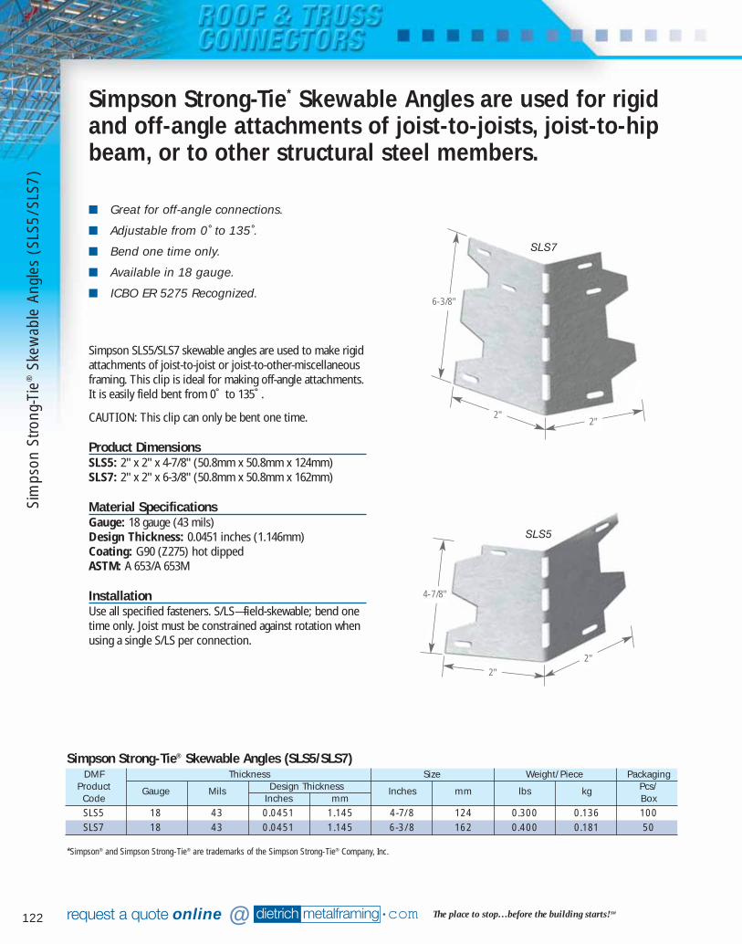
122 dietrich metalframing •com The place to stop…before the building starts! SMrequest a quote online @
■ Great for off-angle connections.
■ Adjustable from 0˚ to 135˚.
■ Bend one time only.
■ Available in 18 gauge.
■ ICBO ER 5275 Recognized.
Simpson SLS5/SLS7 skewable angles are used to make rigidattachments of joist-to-joist or joist-to-other-miscellaneousframing. This clip is ideal for making off-angle attachments.It is easily field bent from 0˚ to 135˚.
CAUTION: This clip can only be bent one time.
Product DimensionsSLS5: 2" x 2" x 4-7/8" (50.8mm x 50.8mm x 124mm)SLS7: 2" x 2" x 6-3/8" (50.8mm x 50.8mm x 162mm)
Material SpecificationsGauge: 18 gauge (43 mils)Design Thickness: 0.0451 inches (1.146mm)Coating: G90 (Z275) hot dippedASTM: A 653/A 653M
InstallationUse all specified fasteners. S/LS—field-skewable; bend onetime only. Joist must be constrained against rotation whenusing a single S/LS per connection.
Simpson Strong-Tie* Skewable Angles are used for rigidand off-angle attachments of joist-to-joists, joist-to-hipbeam, or to other structural steel members.
SLS5
SLS7
6-3/8"
2"2"
4-7/8"
2"
2"
*Simpson® and Simpson Strong-Tie® are trademarks of the Simpson Strong-Tie® Company, Inc.
DMF Thickness Size Weight/Piece PackagingProduct Gauge Mils Design Thickness Inches mm lbs kg Pcs/Code Inches mm BoxSLS5 18 43 0.0451 1.145 4-7/8 124 0.300 0.136 100SLS7 18 43 0.0451 1.145 6-3/8 162 0.400 0.181 50
Simpson Strong-Tie® Skewable Angles (SLS5/SLS7)
Sim
pson
Stro
ng-T
ie®
Skew
able
Ang
les
(SLS
5/SL
S7)
07856 DMF Catalog 118-125.qxd:Pgs 118-125 6/24/10 3:21 PM Page 122

123Available for Overnight Delivery, call 866-638-1908
Roof/Rafter Framing
Typical Construction Details
Table Notes
1) No load duration increase allowed.2) Loads are for one part only. dietrich metalframing •com
to view or download construction details in .dwg, .dxf, and .pdf formats.
Visit our CAD Library at
DMF Simpson Length Allowable Loads
Product Reference
FastenersCode Inches mm F1 F2SLS5 S/LS50 4-7/8 124 4 — #10 500 —SLS7 S/LS70 6-3/8 162 6 — #10 760 —
Simpson Strong-Tie® (SLS5, SLS7)Reinforcing and Skewable Angles
Simpson Strong-Tie
®Skew
able Angles (SLS5/SLS7)
07856 DMF Catalog 118-125.qxd:Pgs 118-125 6/24/10 3:21 PM Page 123
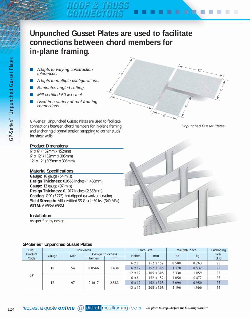
124 dietrich metalframing •com The place to stop…before the building starts! SMrequest a quote online @
■ Adapts to varying constructiontolerances.
■ Adapts to multiple configurations.
■ Eliminates angled cutting.
■ Mill-certified 50 ksi steel.
■ Used in a variety of roof framingconnections.
GP-Series™ Unpunched Gusset Plates are used to facilitateconnections between chord members for in-plane framingand anchoring diagonal tension strapping to corner studs for shear walls.
Product Dimensions6" x 6" (152mm x 152mm)6" x 12" (152mm x 305mm)12" x 12" (305mm x 305mm)
Material SpecificationsGauge: 16 gauge (54 mils) Design Thickness: 0.0566 inches (1.438mm)Gauge: 12 gauge (97 mils)Design Thickness: 0.1017 inches (2.583mm)Coating: G90 (Z275) hot-dipped galvanized coatingYield Strength: Mill-certified SS Grade 50 ksi (340 MPa)ASTM: A 653/A 653M
InstallationAs specified by design.
Unpunched Gusset Plates are used to facilitateconnections between chord members for in-plane framing.
DMF Thickness Plate Size Weight/Piece PackagingProduct Gauge Mils Design Thickness Inches mm lbs kg Pcs/Code Inches mm Skid
6 x 6 152 x 152 0.580 0.263 2516 54 0.0566 1.438 6 x 12 152 x 305 1.170 0.532 25
GP12 x 12 305 x 305 2.330 1.059 256 x 6 152 x 152 1.050 0.477 25
12 97 0.1017 2.583 6 x 12 152 x 305 2.090 0.950 2512 x 12 305 x 305 4.190 1.900 25
GP-Series™ Unpunched Gusset Plates
Unpunched Gusset Plates
12"
12"
12"
6"
6"
6"
GP-
Serie
s™U
npun
ched
Gus
set P
late
s
07856 DMF Catalog 118-125.qxd:Pgs 118-125 6/24/10 3:21 PM Page 124
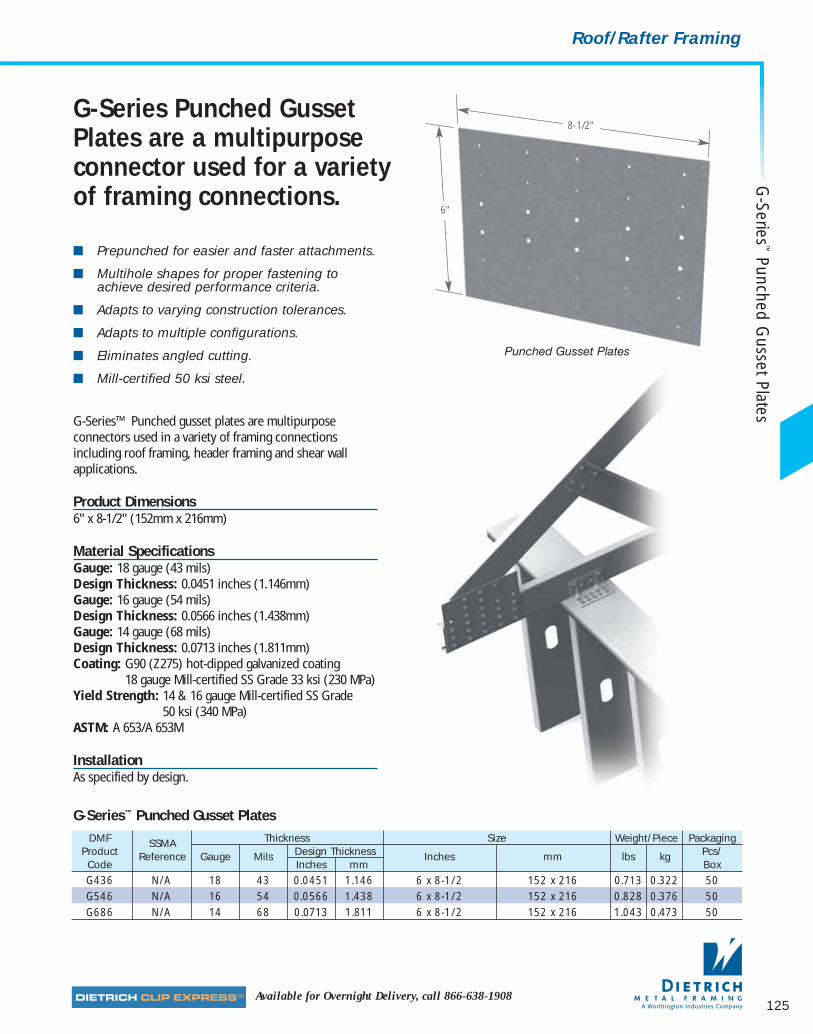
125Available for Overnight Delivery, call 866-638-1908
Roof/Rafter Framing
■ Prepunched for easier and faster attachments.
■ Multihole shapes for proper fastening toachieve desired performance criteria.
■ Adapts to varying construction tolerances.
■ Adapts to multiple configurations.
■ Eliminates angled cutting.
■ Mill-certified 50 ksi steel.
G-Series Punched GussetPlates are a multipurposeconnector used for a varietyof framing connections.
G-Series™ Punched gusset plates are multipurposeconnectors used in a variety of framing connectionsincluding roof framing, header framing and shear wallapplications.
Product Dimensions6" x 8-1/2" (152mm x 216mm)
Material SpecificationsGauge: 18 gauge (43 mils)Design Thickness: 0.0451 inches (1.146mm)Gauge: 16 gauge (54 mils) Design Thickness: 0.0566 inches (1.438mm)Gauge: 14 gauge (68 mils) Design Thickness: 0.0713 inches (1.811mm)Coating: G90 (Z275) hot-dipped galvanized coating
18 gauge Mill-certified SS Grade 33 ksi (230 MPa)Yield Strength: 14 & 16 gauge Mill-certified SS Grade
50 ksi (340 MPa)ASTM: A 653/A 653M
InstallationAs specified by design.
8-1/2"
6"
DMF SSMA Thickness Size Weight/Piece PackagingProduct Reference Gauge Mils Design Thickness Inches mm lbs kg Pcs/Code Inches mm BoxG436 N/A 18 43 0.0451 1.146 6 x 8-1/2 152 x 216 0.713 0.322 50G546 N/A 16 54 0.0566 1.438 6 x 8-1/2 152 x 216 0.828 0.376 50G686 N/A 14 68 0.0713 1.811 6 x 8-1/2 152 x 216 1.043 0.473 50
G-Series™ Punched Gusset Plates
Punched Gusset Plates
G-Series
™Punched G
usset Plates
07856 DMF Catalog 118-125.qxd:Pgs 118-125 6/24/10 3:21 PM Page 125
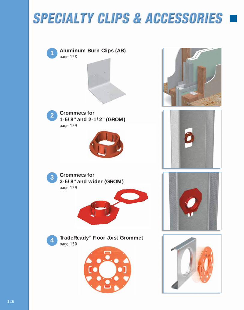
126
1 Aluminum Burn Clips (AB)page 128
3 Grommets for 3-5/8" and wider (GROM)page 129
2 Grommets for 1-5/8" and 2-1/2" (GROM)page 129
4 TradeReady® Floor Joist Grommetpage 130
081016 DMF Catalog 126-142.qxd:Pgs 126-142 6/24/10 3:19 PM Page 126

127
6 Metal Furring Channel Clips (MFCC)page 132
7 Katz Blocking (KA)page 133
8 Custom Fabricated Specialty Products page 134
5 Resilient Sound Isolation Clips (RSIC)page 131
081016 DMF Catalog 126-142.qxd:Pgs 126-142 6/24/10 3:19 PM Page 127

128 dietrich metalframing •com The place to stop…before the building starts! SMrequest a quote online @
Clips melt away under intense heat, allowing a fire-damaged structure to collapse while keeping thefirewall barrier in place to protect the adjacent units.
■ Tested and approved with most major gypsumand shaftliner manufacturers.
■ Clips measure 2" x 2" x 2-1/2".
■ Must be used in conjunction with Dietrich H-Stud Area-Separation Wall Assembly.
■ Prepunched for easy attachment.
DMF Size Thickness PackagingProduct Inches mm in m Pcs/BoxCodeAB 2 x 2 x 2-1/2 50.8 x 50.8 x 63.5 0.050 1.27 500
AB63 2 x 2 x 2-1/2 50.8 x 50.8 x 63.5 0.063 1.60 500*AB63 meets requirements of ICC-ES Legacy Report 92-19
Aluminum Burn Clip (AB)
2-1/2"
2"
2"
Dietrich aluminum burn clips are used as part of the H-Stud area-separation wall assembly and are designed tomelt and break away when exposed to fire. The clips areused to hold the area-separation wall assembly in place atthe floor roof and truss line between adjacent units.
Should a fire break out in one unit, the Aluminum BurnClips on the fire-ridden side of the area-separation wall willmelt, allowing the wall structure for that side to collapse.The burn clips on the non-fire side will remain intact andhold the area-separation wall in place as a barrier tocontain the fire within the unit of origin.
Material SpecificationsClips are manufactured using aluminum alloy.Standard product manufactured with .050 material.Extra-heavy duty product (AB63) manufactured with.063 material is available on request.
InstallationAttach an aluminum breakaway clipto the completed area-separationwall assembly. One clip should belocated at each H-stud on bothsides of the wall. Attach thealuminum breakaway clip to the H-stud with a screw. Attach to theadjacent framing with a screw or a nail.
Alum
inum
Bur
n C
lips
(AB)
081016 DMF Catalog 126-142.qxd:Pgs 126-142 6/24/10 3:19 PM Page 128
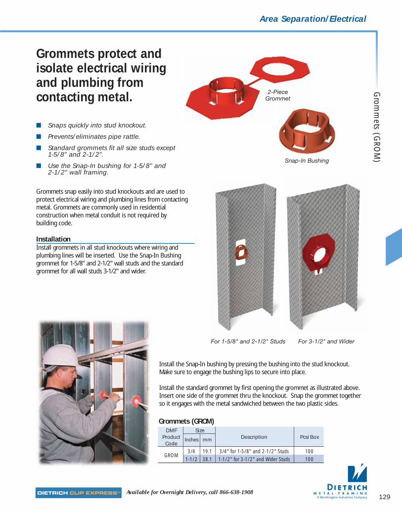
129Available for Overnight Delivery, call 866-638-1908
Area Separation/Electrical
■ Snaps quickly into stud knockout.
■ Prevents/eliminates pipe rattle.
■ Standard grommets fit all size studs except 1-5/8" and 2-1/2".
■ Use the Snap-In bushing for 1-5/8" and 2-1/2" wall framing.
DMF SizeProduct Inches mm Description Pcs/BoxCode
GROM3/4 19.1 3/4" for 1-5/8" and 2-1/2" Studs 100
1-1/2 38.1 1-1/2" for 3-1/2" and Wider Studs 100
Grommets (GROM)
Grommets snap easily into stud knockouts and are used toprotect electrical wiring and plumbing lines from contactingmetal. Grommets are commonly used in residentialconstruction when metal conduit is not required by building code.
InstallationInstall grommets in all stud knockouts where wiring andplumbing lines will be inserted. Use the Snap-In Bushinggrommet for 1-5/8" and 2-1/2" wall studs and the standardgrommet for all wall studs 3-1/2" and wider.
For 1-5/8" and 2-1/2" Studs For 3-1/2" and Wider
2-PieceGrommet
Snap-In Bushing
Grommets protect andisolate electrical wiringand plumbing fromcontacting metal.
Install the Snap-In bushing by pressing the bushing into the stud knockout. Make sure to engage the bushing lips to secure into place.
Install the standard grommet by first opening the grommet as illustrated above.Insert one side of the grommet thru the knockout. Snap the grommet togetherso it engages with the metal sandwiched between the two plastic sides.
Grom
mets (G
ROM
)
081016 DMF Catalog 126-142.qxd:Pgs 126-142 6/24/10 3:19 PM Page 129

130 dietrich metalframing •com The place to stop…before the building starts! SMrequest a quote online @
TradeReady® Grommetprotects and isolateselectrical wiring.■ Snaps quickly into TradeReady® 12” TDW joist
(all gauges)
■ Provides 360˚ cable protection
■ Simplifies cable pull through
■ Delivers compliance with NEC Article300.4(B)(1) and CEC Rule 12-516
■ Aids in the separation of cables to prevent bundling
■ Ideal for ROMEX®/ NM type cables: 6/2, 6/3, 8/2, 8/3, 10/2, 10/3, 12/2, 12/3, 14/2, 14/3, etc…
TradeReady® Grommets are used in construction anytime itis required by building code to protect electrical wiring.The grommet is specially designed for the 12" TradeReady®
Floor Joist System.
Trad
eRea
dy®
Gro
mm
ets
(TD
GR)
DMF Pcs/ Weight/BoxProduct Box lbs kgCodeTDGR 36 12 5.44
UL Pending
TradeReady® Grommets (TDGR)
TradeReady® Grommet
InstallationInsert TradeReady® Grommet into appropriateTradeReady® joist knockout. Snap into place and ensurelocking prongs engage the knockout lip. Optional holessurround the outer perimeter of grommet to allow #10-16 screws to secure to the joist. The smaller slots at the inner perimeter of the grommet are to secure UL approved nylon cable ties.
NEWITEM
UL and UL Classified are trademarks ofUnderwriters Laboratories, Inc.
081016 DMF Catalog 126-142.qxd:Pgs 126-142 6/24/10 3:19 PM Page 130
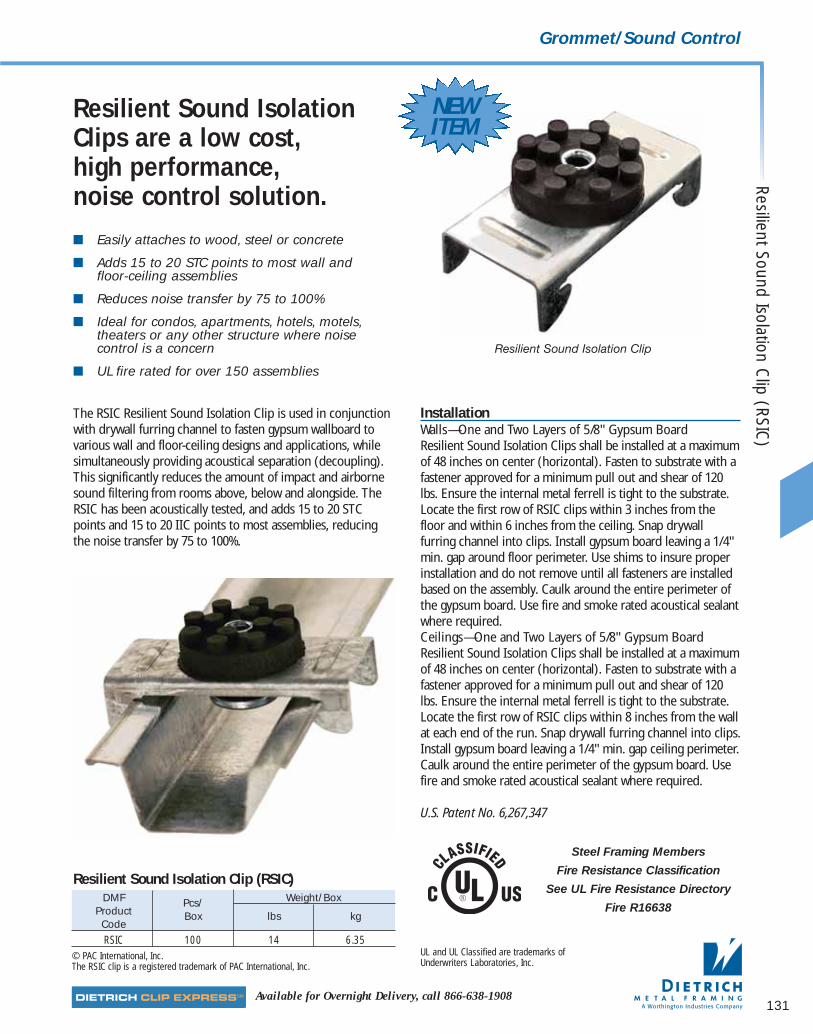
131Available for Overnight Delivery, call 866-638-1908
Grommet/Sound Control
■ Easily attaches to wood, steel or concrete
■ Adds 15 to 20 STC points to most wall and floor-ceiling assemblies
■ Reduces noise transfer by 75 to 100%
■ Ideal for condos, apartments, hotels, motels,theaters or any other structure where noisecontrol is a concern
■ UL fire rated for over 150 assemblies
The RSIC Resilient Sound Isolation Clip is used in conjunctionwith drywall furring channel to fasten gypsum wallboard tovarious wall and floor-ceiling designs and applications, whilesimultaneously providing acoustical separation (decoupling).This significantly reduces the amount of impact and airbornesound filtering from rooms above, below and alongside. TheRSIC has been acoustically tested, and adds 15 to 20 STCpoints and 15 to 20 IIC points to most assemblies, reducingthe noise transfer by 75 to 100%.
Resilient Sound IsolationClips are a low cost, high performance, noise control solution.
InstallationWalls—One and Two Layers of 5/8" Gypsum BoardResilient Sound Isolation Clips shall be installed at a maximumof 48 inches on center (horizontal). Fasten to substrate with afastener approved for a minimum pull out and shear of 120lbs. Ensure the internal metal ferrell is tight to the substrate.Locate the first row of RSIC clips within 3 inches from thefloor and within 6 inches from the ceiling. Snap drywallfurring channel into clips. Install gypsum board leaving a 1/4"min. gap around floor perimeter. Use shims to insure properinstallation and do not remove until all fasteners are installedbased on the assembly. Caulk around the entire perimeter ofthe gypsum board. Use fire and smoke rated acoustical sealantwhere required.Ceilings—One and Two Layers of 5/8" Gypsum BoardResilient Sound Isolation Clips shall be installed at a maximumof 48 inches on center (horizontal). Fasten to substrate with afastener approved for a minimum pull out and shear of 120lbs. Ensure the internal metal ferrell is tight to the substrate.Locate the first row of RSIC clips within 8 inches from the wallat each end of the run. Snap drywall furring channel into clips.Install gypsum board leaving a 1/4" min. gap ceiling perimeter.Caulk around the entire perimeter of the gypsum board. Usefire and smoke rated acoustical sealant where required.
U.S. Patent No. 6,267,347
Resilient Sound Isolation Clip (RSIC
)
DMF Pcs/ Weight/BoxProduct Box lbs kgCodeRSIC 100 14 6.35
© PAC International, Inc.The RSIC clip is a registered trademark of PAC International, Inc.
Resilient Sound Isolation Clip (RSIC)
Resilient Sound Isolation Clip
Steel Framing Members
Fire Resistance Classification
See UL Fire Resistance Directory
Fire R16638
UL and UL Classified are trademarks ofUnderwriters Laboratories, Inc.
NEWITEM
081016 DMF Catalog 126-142.qxd:Pgs 126-142 6/24/10 3:19 PM Page 131

132 dietrich metalframing •com The place to stop…before the building starts! SMrequest a quote online @
■ Securely fastens furring channel to U-channel.
■ Corrosion-resistant galvanized wire.
■ 500 pieces per box.
Dietrich Metal Furring Channel Clips are made ofgalvanized wire and used to attach Dietrich™ metal furringchannels to 1-1/2" U-channels in ceiling gridwork. Clipsmust be installed on alternating sides of the 1-1/2"channels. Use tie wire when clips cannot be alternated.
Clips should only be used when single-layer gypsum orsingle-layer veneer plaster base is used.
Material SpecificationsDietrich Metal Furring Channel Clips, made of galvanizedwire, are used in attaching metal channels to 1-1/2 " cold-rolled channel ceiling grillwork. For use with gypsumpanels or with single-layer veneer gypsum plaster base. See illustration.
Quickly facilitates the attachment of metal furringchannel to 1-1/2" U-channel in ceiling assemblies.
InstallationMetal furring channel clips must be attached on alternatesides of the 1-1/2" U-channels. Use tie wire when clipscannot be alternated.
2-9/16"
1-5/8"
2"
DMF Pcs/ Weight/BoxProduct Box lbs kgCodeMFCC 500 20 9.05
Metal Furring Channel Clip (MFCC)
Met
al F
urrin
g C
hann
el C
lips
(MFC
C)
081016 DMF Catalog 126-142.qxd:Pgs 126-142 6/24/10 3:19 PM Page 132

133Available for Overnight Delivery, call 866-638-1908
Ceilings
■ Precut for 16" and 24" O.C. spacing.
■ Coped and prepunched flanges for easyinstallation.
■ Eliminates wood blocking and labor-intensivenotching of metal framing.
Dietrich Katz™ blocking is specifically manufactured toladder frame between parallel framing members andprovide for the attachment of the top of the interiornonstructural walls when trusses or floor joists run parallelto the walls. Katz blocks are secured to the floor joists orroof trusses with screws or nails.
Material SpecificationsGauge: 25 gauge (18 mils)Design Thickness: 0.0188 inches (0.478 mm)Coating: G40 (Z120) hot-dipped galvanized or
equivalent corrosion resistance.Yield Strength: 33 ksi (230 MPa)ASTM: A 653/A 653M
InstallationInsert the precut structural blocking to fit securely betweenthe underside of the floor joist or roof trusses. Using #8 minimum self-drilling screws or an 8d nail, secure theblocking to the joist or truss flanges using the prepunchedholes. Install Katz blocking a maximum of 4' O.C. or per specification.
DMF Size Length Weight/PieceProduct Inches mm Inches mm lbs kgCode
KA 3-5/8 92.116 406 0.680 0.31024 610 1.160 0.520
Katz Blocking (KA)
16", 24"
3-5/8"
Katz
1-1/4"
Quick, efficient method to ladder frame betweenparallel joists or trusses.
Katz Blocking (KA)
081016 DMF Catalog 126-142.qxd:Pgs 126-142 6/24/10 3:19 PM Page 133
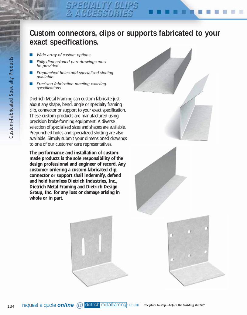
134 dietrich metalframing •com The place to stop…before the building starts! SMrequest a quote online @
Dietrich Metal Framing can custom fabricate justabout any shape, bend, angle or specialty framingclip, connector or support to your exact specification.These custom products are manufactured usingprecision brake-forming equipment. A diverseselection of specialized sizes and shapes are available.Prepunched holes and specialized slotting are alsoavailable. Simply submit your dimensioned drawingsto one of our customer care representatives.
The performance and installation of custom-made products is the sole responsibility of thedesign professional and engineer of record. Anycustomer ordering a custom-fabricated clip,connector or support shall indemnify, defendand hold harmless Dietrich Industries, Inc.,Dietrich Metal Framing and Dietrich DesignGroup, Inc. for any loss or damage arising inwhole or in part.
Custom connectors, clips or supports fabricated to yourexact specifications.■ Wide array of custom options.
■ Fully dimensioned part drawings must be provided.
■ Prepunched holes and specialized slottingavailable.
■ Precision fabrication meeting exactingspecifications.
Cus
tom
-Fab
ricat
ed S
peci
alty
Pro
duct
s
081016 DMF Catalog 126-142.qxd:Pgs 126-142 6/24/10 3:19 PM Page 134
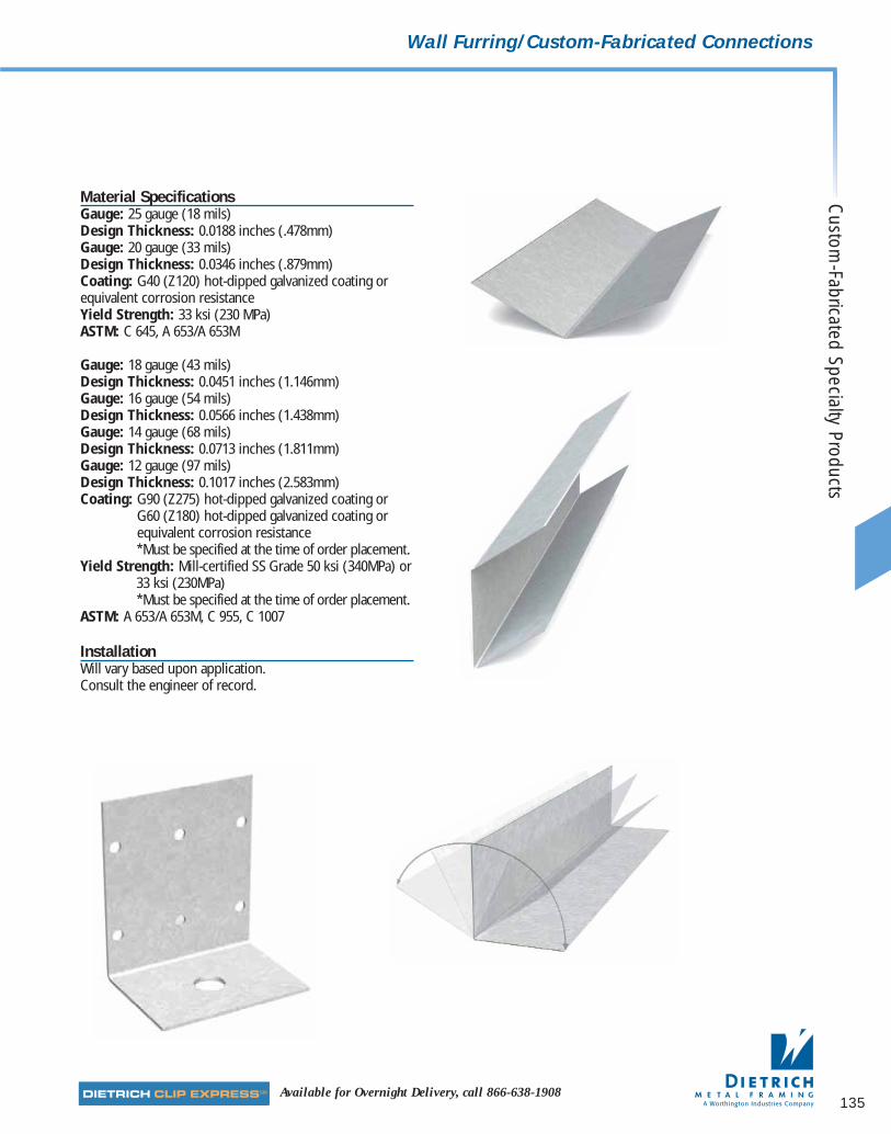
135Available for Overnight Delivery, call 866-638-1908
Wall Furring/Custom-Fabricated Connections
Material SpecificationsGauge: 25 gauge (18 mils)Design Thickness: 0.0188 inches (.478mm)Gauge: 20 gauge (33 mils) Design Thickness: 0.0346 inches (.879mm)Coating: G40 (Z120) hot-dipped galvanized coating orequivalent corrosion resistanceYield Strength: 33 ksi (230 MPa)ASTM: C 645, A 653/A 653M
Gauge: 18 gauge (43 mils) Design Thickness: 0.0451 inches (1.146mm)Gauge: 16 gauge (54 mils)Design Thickness: 0.0566 inches (1.438mm)Gauge: 14 gauge (68 mils)Design Thickness: 0.0713 inches (1.811mm)Gauge: 12 gauge (97 mils) Design Thickness: 0.1017 inches (2.583mm)Coating: G90 (Z275) hot-dipped galvanized coating or
G60 (Z180) hot-dipped galvanized coating orequivalent corrosion resistance*Must be specified at the time of order placement.
Yield Strength: Mill-certified SS Grade 50 ksi (340MPa) or33 ksi (230MPa)*Must be specified at the time of order placement.
ASTM: A 653/A 653M, C 955, C 1007
InstallationWill vary based upon application. Consult the engineer of record.
Custom
-Fabricated Specialty Products
081016 DMF Catalog 126-142.qxd:Pgs 126-142 6/24/10 3:19 PM Page 135
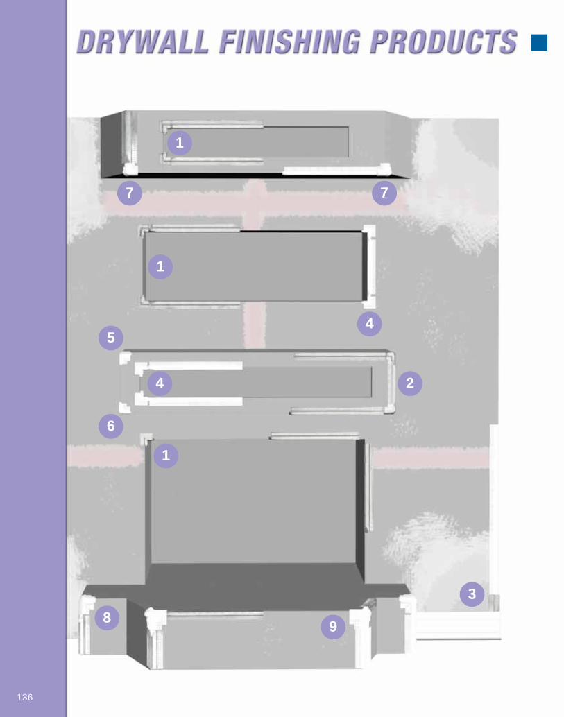
136
1
7 7
1
1
45
6
4 2
89
3
081016 DMF Catalog 126-142.qxd:Pgs 126-142 6/24/10 3:19 PM Page 136
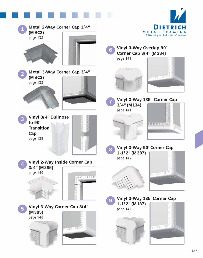
137
1 Metal 2-Way Corner Cap 3/4"(MBC2)page 138
2 Metal 3-Way Corner Cap 3/4"(MBC3)page 138
3 Vinyl 3/4" Bullnoseto 90º
TransitionCappage 139
4 Vinyl 2-Way Inside Corner Cap3/4" (M285)page 140
5 Vinyl 3-Way Corner Cap 3/4"(M385)page 140
6 Vinyl 3-Way Overlap 90º
Corner Cap 3/4" (M384)page 141
7 Vinyl 3-Way 135º Corner Cap3/4" (M134)page 141
8 Vinyl 3-Way 90º Corner Cap 1-1/2" (M387)page 142
9 Vinyl 3-Way 135º Corner Cap 1-1/2" (M187)page 142
081016 DMF Catalog 126-142.qxd:Pgs 126-142 6/24/10 3:19 PM Page 137
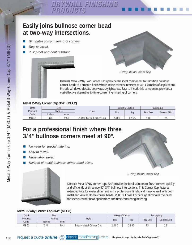
138 dietrich metalframing •com The place to stop…before the building starts! SMrequest a quote online @
■ No need for special mitering.
■ Easy to install.
■ Huge labor saver.
■ Favorite of metal bullnose corner bead users.
■ Eliminates costly mitering of corners.
■ Easy to install.
■ Rust proof and dent resistant.
DMF Size Weight/Carton PackagingProduct Radius Style lbs kg Pcs/Box Boxes/SkidCode Inches mmMBC2 3/4 19.1 2-Way Metal Corner Cap 2.000 0.905 100 25
Metal 2-Way Corner Cap 3/4" (MBC2)
DMF Size Weight/Carton PackagingProduct Radius Style lbs kg Pcs/Box Boxes/SkidCode Inches mmMBC3 3/4 19.1 3-Way Metal Corner Cap 2.000 0.905 75 25
Metal 3-Way Corner Cap 3/4" (MBC3)
2-Way Metal Corner Cap
3-Way Metal Corner Cap
Dietrich Metal 3-Way corner caps 3/4" provide the ideal solution to finish corners quicklyand efficiently at three-way 90° 3/4" bullnose intersections. This Corner Cap featuresextended tabs for easier alignment and a professional finish, and it works well with bothmetal and vinyl bullnose corner beads. M385 Bullnose Corner Cap eliminates the needfor special corner bead applications and time-consuming mitering.
For a professional finish where three3/4" bullnose corners meet at 90°.
Dietrich Metal 2-Way 3/4" Corner Caps provide the ideal component to transition bullnosecorner beads to a smooth finish where inside corners intersect at 90°. Examples of applicationsinclude windows, closets, doorways, skylights, etc. Easy to install, this component provides acost-effective alternative to time-consuming mitering of corners.
Easily joins bullnose corner bead at two-way intersections.
Met
al 2
-Way
Cor
ner
Cap
3/4
" (M
BC2)
& M
etal
3-W
ay C
orne
r C
ap 3
/4"
(MBC
3)
081016 DMF Catalog 126-142.qxd:Pgs 126-142 6/24/10 3:19 PM Page 138
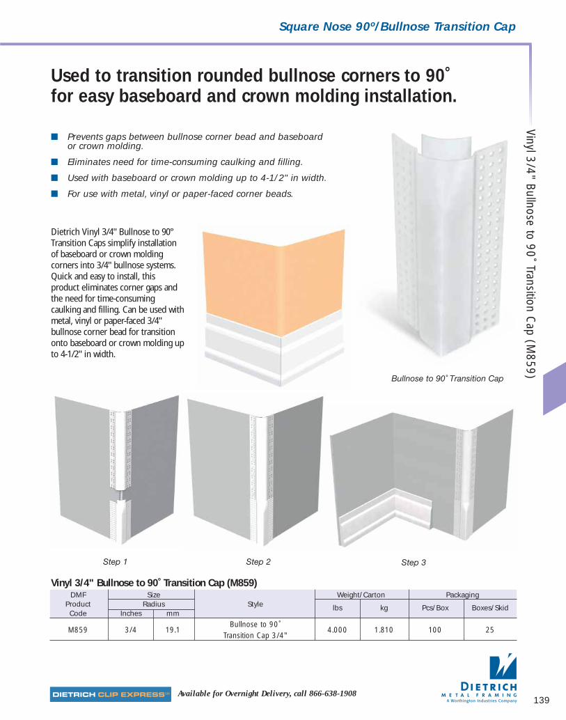
139Available for Overnight Delivery, call 866-638-1908
Square Nose 90º/Bullnose Transition Cap
■ Prevents gaps between bullnose corner bead and baseboardor crown molding.
■ Eliminates need for time-consuming caulking and filling.
■ Used with baseboard or crown molding up to 4-1/2" in width.
■ For use with metal, vinyl or paper-faced corner beads.
Dietrich Vinyl 3/4" Bullnose to 90°Transition Caps simplify installationof baseboard or crown moldingcorners into 3/4" bullnose systems.Quick and easy to install, thisproduct eliminates corner gaps andthe need for time-consumingcaulking and filling. Can be used withmetal, vinyl or paper-faced 3/4"bullnose corner bead for transitiononto baseboard or crown molding upto 4-1/2" in width.
Used to transition rounded bullnose corners to 90˚ for easy baseboard and crown molding installation.
DMF Size Weight/Carton PackagingProduct Radius Style lbs kg Pcs/Box Boxes/SkidCode Inches mm
M859 3/4 19.1Bullnose to 90˚
4.000 1.810 100 25Transition Cap 3/4"
Vinyl 3/4" Bullnose to 90˚ Transition Cap (M859)
Bullnose to 90˚ Transition Cap
Step 1 Step 2 Step 3
Vinyl 3/4" Bullnose to 90˚ Transition Cap (M
859)
081016 DMF Catalog 126-142.qxd:Pgs 126-142 6/24/10 3:19 PM Page 139
140 dietrich metalframing •com The place to stop…before the building starts! SMrequest a quote online @
■ Eliminates costly mitering of corners
■ Easy to install
■ Rust proof and dent resistant.
■ No need for special corner bead applications.
■ Easy to install.
■ Huge labor saver.
■ Added tabs for enhanced corner alignment.
2-Way Inside 3/4" Bullnose C orner Cap 90˚
For a professional finish where three3/4" bullnose corners meet at 90°.
Dietrich Vinyl 3-Way 90˚ Corner Caps 3/4" provide the ideal solution to finish cornersquickly and efficiently at three-way 90˚ 3/4" bullnose intersections. This corner capfeatures extended tabs for easier alignment and a professional finish, and it works wellwith both metal and vinyl bullnose corner beads.
M385 Bullnose Corner Cap eliminates the need for special corner bead applications andtime-consuming mitering.
For a professional finish where twobullnose corners meet at 90°.
Dietrich Vinyl 2-Way Inside 90˚ Corner Caps 3/4" provide the ideal component to transition bullnosecorner beads to a crisp finish where inside corners intersect at 90°. Examples of applications includewindows, closets, doorways, skylights, etc.
Easy to install, this component provides a cost-effective alternative to time-consuming mitering of corners.
DMF Size Weight/Carton PackagingProduct Radius Style lbs kg Pcs/Box Boxes/SkidCode Inches mmM285 3/4 19.1 Plastic 2-Way Corner Cap 2.000 0.905 100 25
Vinyl 2-Way Inside 90˚ Corner Cap 3/4" (M285)
DMF Size Weight/Carton PackagingProduct Radius Style lbs kg Pcs/Box Boxes/SkidCode Inches mmM385 3/4 19.1 Plastic 3-Way Corner Cap 2.000 0.905 100 25
Vinyl 3-Way 90˚ Corner Cap 3/4" (M385)
3-Way 3/4" Bullnose Corner Cap 90˚
Viny
l 2-W
ay In
side
90˚
Cor
ner
Cap
3/4
" (M
285)
& V
inyl
3-W
ay 9
0˚ C
orne
r C
ap 3
/4"
(M38
5)
081016 DMF Catalog 126-142.qxd:Pgs 126-142 6/24/10 3:19 PM Page 140
141Available for Overnight Delivery, call 866-638-1908
Bullnose Corner Caps 3/4”
■ Substantially reduces labor.
■ No need for special corner bead applications.
■ Easy to install.
■ Works with metal and vinyl bullnose corner beads.
Dietrich Vinyl 3-Way Overlap 90˚ Corner Caps 3/4" provide the ideal solution to finishcorners quickly and efficiently at three-way 90˚ bullnose intersections. Easy to install, thisrust-proof and dent-resistant vinyl cap solves many potential finishing problems.
■ No need for special corner bead applications.
■ Easy to install.
■ Rust proof and dent resistant.
Vinyl 3-Way Overlap90˚ Corner Cap 3/4"
Vinyl 3-Way 135˚ Corner Cap 3/4"
Provides a professional finish at 135° off-angle, three-way 3/4" bullnose intersections.
Dietrich 3-Way 135˚ off-angle 3/4" bullnose corner caps provide the ideal solution to join andfinish corners at three-way off-angle 135˚ bullnose intersections. The bullnose cap eliminatestime-consuming mitering and creates a professional transition.
Use to finish three-way bullnose 90° intersections.
DMF Size Weight/Carton PackagingProduct Radius Style lbs kg Pcs/Box Boxes/SkidCode Inches mmM134 3/4 19.1 3-Way Off-Angle Corner Cap 3/4" 2.000 0.905 50 25
Vinyl 3-Way 135˚ Corner Cap 3/4" (M134)
DMF Size Weight/Carton PackagingProduct Radius Style lbs kg Pcs/Box Boxes/SkidCode Inches mmM384 3/4 19.1 Plastic 3-Way Overlap Corner Cap 2.000 0.905 50 25
Vinyl 3-Way Overlap 90˚ Corner Cap 3/4" (M384)
Vinyl 3-Way O
verlap 90˚ Corner Cap 3/4" (M384) & Vinyl 3-W
ay 135˚ Corner C
ap 3/4" (M134)
081016 DMF Catalog 126-142.qxd:Pgs 126-142 6/24/10 3:19 PM Page 141
142 dietrich metalframing •com The place to stop…before the building starts! SMrequest a quote online @
■ Substantially reduces labor.
■ No need for special corner bead applications.
■ Easy to install.
■ Rust proof and dent resistant.
Dietrich Vinyl 3-Way 135˚ Corner Caps 1-1/2" provide the ideal solution to finishcorners quickly and efficiently at three-way off-angle 1-1/2" bullnose intersections.These caps eliminate time-consuming mitering and create a professional transition. Easyto install, extended tabs and flanges ensure proper corner alignment.
Provides a professional finish at three-way off-angle 1-1/2" bullnose intersections.
■ Creates a soft, rounded appearance.
■ No need for special corner bead applications.
■ Easy to install.
■ Huge labor savings.
■ Rust proof and dent resistant.
Dietrich Vinyl 3-Way 90˚ Corner Cap 1-1/2" provides the ideal solution to finish corners quicklyand efficiently at three-way 90˚ 1-1/2" bullnose intersections. It’s specially designed to deliveran ultra-soft corner appearance associated with 1-1/2" bullnose corner bead. Eliminates theneed for special corner bead applications and time-consuming mitering. Easy to install,extended tabs and flanges ensure proper corner alignment and professional finish.
Vinyl 3-Way 135˚ Corner Cap 1-1/2"
Vinyl 3-Way 90ºCorner Cap 1-1/2"
Provides a professional finish at three-way off-angle 1-1/2" bullnose intersections.
DMF Size Weight/Carton PackagingProduct Radius Style lbs kg Pcs/Box Boxes/SkidCode Inches mmM387 1-1/2 38.1 Plastic 3-Way Corner Cap 1-1/2" 2.000 0.905 50 25
Vinyl 3-Way 90˚ Corner Cap 1-1/2" (M387)
DMF Size Weight/Carton PackagingProduct Radius Style lbs kg Pcs/Box Boxes/SkidCode Inches mmM187 1-1/2 38.1 3-Way Off-Angle Corner Cap 1-1/2" 2.000 0.905 50 25
Vinyl 3-Way 135˚ Corner Cap 1-1/2" (M187)
Viny
l 3-W
ay 9
0˚ C
orne
r Cap
1-1
/2"
(M38
7)&
Viny
l 3-W
ay 1
35˚
Cor
ner
Cap
1-1
/2"
(M18
7)
081016 DMF Catalog 126-142.qxd:Pgs 126-142 6/24/10 3:19 PM Page 142
Plea
se R
etur
n Fa
x to
Die
trich
Des
ign
Gro
up21
9.93
2.41
41▲
Contact Information
Your Name
Your Company
Phone
Fax
▲
Project Information
Project Name
Location
Bid Date
dietrich metalframing •comThe place to stop…before the building starts! SM
Opening Framing
Preliminary Sizing Sheet
NEW!! HDS® Framingby Dietrich Metal Framing
▲
Wind Load Information
Building Code
Year
Basic Wind Speed mph
Building Classification
Exposure
Importance Factor
Wind Load Required by Specs psf
▲
Building Geometry
Average Bldg Height
Least Bldg Width
▲
Stud Size 3-5/8"
6"
▲
Stud Spacing 16" Other
24" "
▲
Dead Load Information
Wall Dead Load psf
▲
Deflection Information
Wall Deflection Limit L/
Typical Wall Deflection Guidelines
Brick - L/600 Stucco - L/360 EIFS - L/240
Parapet Height
(If Applicable)
Wall Height
(Total Wall Height)
Opening Height
Sill Height
(If Applicable)
Opening Width
▲
Opening Dimensions
Opening
143
Patent Pending
081016 DMF Catalog 143-152.qxd:Pgs 143-152 6/24/10 3:20 PM Page 143

dietrich metalframing •com
MATERIAL CERTIFICATION
Design Specification (AISI)“Specifications for the Design of Cold-Formed Steel Structural Members”
Product Specification (ASTM)Drywall Nonload-Bearing (Nonstructural) Framing and Accessories ........................C 645
Structural Framing and Accessories ..........................................................................C 955
Plastering Steel Products ..........................................................................................C 847
Veneer and Plaster Accessories ....................................................................C 841/C 1063
Beads and Trims – Metal – Paper – Vinyl ................................................................C 1047
Material Specification (ASTM)Drywall Nonload-Bearing (Nonstructural) Framing – No accessories ..........A 1003 (NS33)
Structural Framing and Accessories ......................A 1003 (ST33L, ST33H, ST50L, ST50H)
Plastering Steel Products ..........................................................................................A 653
Veneer and Plaster Accessories ........................................................................A 653/B 69
Beads and Trims – Metal – Paper – Vinyl ........................................................A 653/A 591
Coating Specification (ASTM)Drywall Nonload-Bearing (Nonstructural) Framing and Accessories ........................C 645
Structural Framing and Accessories ........................................................................C 955*
Plastering Steel Products ..........................................................................................A 653
Veneer and Plaster Accessories ..............................................................................C 1063
Beads and Trims – Metal – Paper – Vinyl ................................................................C 1047
Additional InformationMSDS, limiting heights, code-body reports and individual product specification sheets areavailable at www.dietrichmetalframing.com
* Structural Framing products are available with a variety of protective coatings. G60 zinc coatingsmeet the most widely applicable building codes and we are able to provide certified G60 productthat meets the G60 coating weight provisions of ASTM to C 955. Certified G90 coatings are anenhanced option that can be requested for highly corrosive environments. G60E coatings are aneconomical choice. G60E coatings for structural products will pass the 100-hour salt spray testapplicable to “equivalent” coatings under ASTM A 1003, but cannot be certified by any supplier tomeet the G60 minimum coating standard under ASTM C 955. The buyer is solely responsible toassure that products purchased properly satisfy any applicable code or specification.
144
ASTM SpecificationDescriptionsA 591Standard Specification for Steel Sheet,Electrolytic Zinc-Coated, for Light CoatingWeight [Mass] Applications
A 653Standard Specification for Steel Sheet, Zinc-Coated (Galvanized) or Zinc-Iron Alloy Coated(Galvannealed) by Hot-Dip Process
A 1003Standard Specification for Steel Sheet,Carbon, Metallic- and Nonmetallic-Coated for Cold Formed Framing Members
B 69Standard Specification for Rolled Zinc
C 645Standard Specification for Nonstructural SteelFraming Members
C 841Standard Specification for Installation ofInterior Lathing and Furring
C 847Standard Specification for Metal Lath
C 955Standard Specification for Load-Bearing(Transverse and Axial) Steel Studs, Runners(Tracks), and Bracing or Bridging for ScrewApplication of Gypsum Panel Products andMetal Plaster Bases.
C 1047Standard Specifications for Accessories forGypsum Wallboard and Gypsum Veneer Base
C 1063Standard Specifications for Installation ofLathing and Furring to Receive Interior andExterior Portland Cement-Based Plaster.
081016 DMF Catalog 143-152.qxd:Pgs 143-152 6/24/10 3:20 PM Page 144
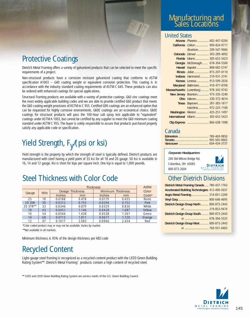
145
Protective CoatingsDietrich Metal Framing offers a variety of galvanized products that can be selected to meet the specificrequirements of a project.
Non-structural products have a corrosion resistant galvanized coating that conforms to ASTMspecification A1003 – G40 coating weight or equivalent corrosion protection. This coating is inaccordance with the industry standard coating requirements of ASTM C 645. These products can alsobe ordered with enhanced coatings for special applications.
Structural Framing products are available with a variety of protective coatings. G60 zinc coatings meetthe most widely applicable building codes and we are able to provide certified G60 product that meetsthe G60 coating weight provisions of ASTM to C 955. Certified G90 coatings are an enhanced option thatcan be requested for highly corrosive environments. G60E coatings are an economical choice. G60Ecoatings for structural products will pass the 100-hour salt spray test applicable to “equivalent”coatings under ASTM A 1003, but cannot be certified by any supplier to meet the G60 minimum coatingstandard under ASTM C 955. The buyer is solely responsible to assure that products purchased properlysatisfy any applicable code or specification.
Yield Strength, Fy/(psi or ksi)Yield strength is the property by which the strength of steel is typically defined. Dietrich products aremanufactured with steel having a yield point of 33 ksi for all 18 and 20 gauge. 50 ksi is available in16, 14 and 12 gauge. Ksi is short for kips per square inch. One kip is equal to 1,000 pounds.
Recycled ContentLight-gauge steel framing is recognized as a recycled content product with the LEED Green BuildingRating System**. Dietrich Metal Framing™ products contain a high content of recycled steel.
** LEED and LEED Green Building Rating System are service marks of the U.S. Green Building Council.
Minimum thickness is 95% of the design thickness per AISI code
Thickness ASTM
Gauge Mils Design Thickness Minimum Thickness ColorInches mm Inches mm Code*
25 18 0.0188 0.478 0.0179 0.455 None20 DW 30 0.0312 0.792 0.0296 0.752 Pink
20 STR** 33 0.0346 0.879 0.0329 0.836 White18 43 0.0451 1.146 0.0428 1.087 Yellow16 54 0.0566 1.438 0.0538 1.367 Green14 68 0.0713 1.811 0.0677 1.720 Orange12 97 0.1017 2.583 0.0966 2.454 Red
Steel Thickness with Color Code
*Color coded product may or may not be available. Varies by market.
**Not available in all markets.
Manufacturing and Sales Locations
United StatesArizona Phoenix ............... 602-447-0204
California Colton ................ 909-824-9717Stockton .............. 209-547-9066
Colorado Denver ................ 303-289-4092Florida Miami .................. 305-652-5423
Georgia McDonough........ 678-304-5500Hawaii Kapolei ................ 808-682-5747Illinois Joliet ................... 815-207-0110
Indiana Hammond ........... 219-931-3741Kansas Lenexa ................ 913-599-2026
Maryland Baltimore............. 410-477-8700Massachusetts Lunenburg........... 978-342-9742
New Jersey Boonton............... 973-335-3240Ohio Warren ................ 330-372-4014
Texas Baytown .............. 281-383-1617Hutchins .............. 972-225-1100
Washington Renton ................ 425-251-1497International Miami .................. 305-652-5423
Clip Express ........................... 866-638-1908
CanadaEdmonton ....................................... 780-469-9850Toronto ........................................... 905-565-9665Vancouver ...................................... 604-434-3737
Other Dietrich DivisionsDietrich Metal Framing Canada ..... 780-437-1763
Accelerated Building Technologies 412-490-5037
Aegis Metal Framing ...................... 314-851-2200
Vinyl Corp. ...................................... 800-648-4695
Dietrich Design Group North .......... 800-873-2443
or ............................... 219-853-9474
Dietrich Design Group South.......... 800-873-2443
or .............................. 678-304-5525
Dietrich Design Group West ........... 800-873-2443
or .............................. 760-931-0465
Corporate Headquarters
200 Old Wilson Bridge Rd.
Columbus, OH 43085
800-873-2604
081016 DMF Catalog 143-152.qxd:Pgs 143-152 6/24/10 3:20 PM Page 145

2A
c123.
2.03 MA. Stee
steelstiffeas fol1. Min
Sectindica
2. Flang
B. Steel Tracsteel trackwith straig
C. Headers, Japroprietary h
LEED*
CERTIFICATION
146
Build Green with Dietrich Metal FramingLEED® stands for Leadership in Energy &Environmental Design. LEED® GreenBuilding Rating System, as promulgated bythe U.S. Green Building Council, is to improveenvironmental and economic performance
of commercial buildings using established or advanced industryprinciples, practices, materials and standards.
Dietrich recognizes the importance and growing agenda ofLEED®. We are members of the U.S. Green Building Counciland have LEED® Accredited Professionals on staff.
Dietrich Metal Framing can contribute toward LEED credits inseveral areas. In addition to recycled content, the environ-mental impacts resulting from transportation can be reducedas our sales and manufacturing facilities are located within300 miles of 85% of the U.S. population.
Contact your Dietrich representative. Ask how our metal framingproducts and accessories can contribute toward achieving LEED credits on your next project.
Materials and ResourcesMaterials & Resources Credit 4: Recycled Contentintends to increase demand for building products thatincorporate recycled content materials, therefore reducing impacts resulting from extraction and processing of new virgin materials. As discussed anddemonstrated below, steel building products contributepositively toward earning points under Credit 4.1 andCredit 4.2. The following is required by LEED Version 2.2:
Credit 4.1 (1 point) “Use materials with recycled contentsuch that the sum of post-consumer recycled contentplus one-half of the pre-consumer content constitutes atleast 10% of the total value of the materials in the project.”
Credit 4.2 (1 point) “Use materials with recycled contentsuch that the sum of post-consumer recycled contentplus one-half of the pre-consumer content constitutes atleast 20% of the total value of the materials in the project.”
“The value of the recycled content portion of a materialor furnishing shall be determined by dividing the weightof recycled content in the item by the total weight of allmaterial in the item, then multiplying the resulting percentage by the total value of the item.” Since steel(the material) and steel (the building product) are thesame, the value of the steel building product is directlymultiplied by steel’s recycled content, or:
Steel Recycled Content Value = (Value of Steel Product)(Post-Consumer % + 1/2 Pre-Consumer %)
The formula above calculates the post-consumer andpre-consumer recycled content percentages for NorthAmerican steel building products. These percentagesand values of steel building products are easily enteredinto the LEED Letter Template spreadsheet for calculation. To illustrate the application of these steelrecycled content values to LEED, manual calculations areshown below for typical Basic Oxygen Furnace (BOF) andElectric Arc Furnace (EAF) steel building products withnominal $10,000 purchases, using 2005 data. Steelbuilding products include light gauge steel framing,structural steel framing (wide flange beams, channels,angles, etc.), rebar, roofing, siding, decking, doors andsashes, windows, ductwork, pipe, fixtures, hardware(hinges, handles, braces, screws, nails), culverts, stormdrains, and manhole covers.
BOF Steel Recycled Content Value for Typical Product:
Steel Stud FramingValue = ($10,000) (24.6% + 1/2 6.6%) = ($10,000)
(27.9%) = $2,790(Exceeds 10% and 20% goals)
EAF Steel Recycled Content Value for Typical Product:
Wide-Flange Structural Steel FramingValue = ($10,000) (56.6% + 1/2 32.7%) = ($10,000)
(72.95%) = $7,295(Exceeds 10% and 20% goals)
Information courtesy of The Steel Recycling Institute
* LEED is a registered service mark of the U.S. Green Building Council
dietrich metalframing •com
081016 DMF Catalog 143-152.qxd:Pgs 143-152 6/24/10 3:20 PM Page 146

The following specificationoptions are available fromDietrich Metal Framing:
PRODUCT MASTERSPEC*
MANUSPEC™
ARCAT**
DIETRICH METAL FRAMINGDietrich Metal Framing Guide Specifications are written in theCSI three-part format and in CSI page format.
dietrich metalframing •com
4SPECS.COM
Dietrich Metal Framing provides the design, engineering or building project specifier with awide array of specification resources includingthree-part Guide Specifications, as well as complimentary specification reviews. Over time,project specifications can become outdated orobsolete. Our specification specialist will provideyou with recommendations and suggestions toimprove the performance of your project specifications. For a complimentary specificationreview, contact us at 724.459.1429 or [email protected]
ARCHITECTURAL SPECIFICATIONSFOR COLD-FORMED METAL
PART 2 - PRODUCTS2.01 MANUFACTURERSA. Manufacturers: Subject to compliance with
requirements, provide cold-formed metal framing by
one of the following:1. Clark Steel Framing Industries.2. Consolidated Systems. Inc.3. Dale Industries. Inc.4. Dietrich Metal Framing5. CEMCO
6. Unimast, Inc.2.02 MATERIALSA. Steel Sheet: ASTM A 653/A 653M, structural steel,
zinc coated, of grade and coating as follows: ASTM
A1003 Standard Specification for Steel Sheet,
Carbon, Metallic-and Nonmetallic-Coated for
Cold-Formed Framing Members of grade and
coating weight as follows:1. Grade: 33 for 18 gauge and lighter units.
2. Grade: 50 (340) for 16 gauge and heavier units.
3. Coating: G60 or equivalent per ASTM C955.2.03 METAL FRAMINGA. Steel Studs: Manufacturer's standard C-shaped
steel studs, of web depths indicated, punched, with
stiffened flanges, complying with ASTM C 955, and
as follows:1. Minimum Base-Metal Thickness: to satisfy
Section Modulus (S) and Moment of Inertia
indicated. 2. Flange Width: Minimum 1-3/8 inches.Steel Track: Manufacturer's standard U-shaped
teel track, of web depths indicated, un-punched,
ith straight flanges, complying with ASTM C 955.aders, Jambs and Posts: Mprietary h
2.04 NON-LOAD-BEARING FRAMINGA. Steel Studs: Manufacturer's standard C-shaped
steel studs, of web depths indicated, punched, with
stiffened flanges, complying with ASTM C 955.B. Steel Track: Manufacturer's standard U-shaped
steel track, of web depths indicated, un-punched,
with unstiffened flanges, complying with ASTM C
955.
C. Double Deflection Tracks: Manufacturer's double,
deep-leg, U-shaped steel tracks, consisting of
nested inner and outer tracks; unpunched, with
unstiffened flanges.1. Single slotted slip deflection: Manufacturer’s
single, deep-leg, U-shaped slotted deflection
track with 1-1/2” vertical slots to ensure positive
attachment; unpunched, with unstiffened flanges,
of web depth to contain studs while allowing free
vertical movement designed to support horizontal
and lateral loads and transfer them to the
primary structure2. Double Deflection Track: Manufacturer’s double,
deep-leg, U-shaped steel tracks, consisting of
nested inner and outer tracks; unpunched, with
unstiffened flanges3. Outer Track: Of web depth to allow free vertical
movement of inner track, with flanges designed
to support horizontal and lateral loads.
D. Vertical Deflection Clips: Manufacturer's standard
clips, capable of accommodating up-ward and
downward vertical displacement of primary
structure.
2.05 FLOOR
®
* MASTERSPEC is a registered trademark ofthe American Institute of Architects
** ARCAT is a registered trademark ofARCAT, Inc.
DIETRICH specification
OPTIONS
147
081016 DMF Catalog 143-152.qxd:Pgs 143-152 6/24/10 3:20 PM Page 147
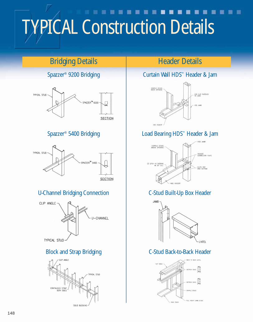
TYPICAL Construction Details
Bridging Details Header Details
Spazzer® 9200 Bridging Curtain Wall HDS™ Header & Jam
Spazzer® 5400 Bridging Load Bearing HDS™ Header & Jam
U-Channel Bridging Connection C-Stud Built-Up Box Header
Block and Strap Bridging C-Stud Back-to-Back Header
148
081016 DMF Catalog 143-152.qxd:Pgs 143-152 6/24/10 3:20 PM Page 148

Head of Wall Deflection Typical Details
SLP-TRK® Slotted Track
Long Leg Track with Spazzer® 5400
Long Leg Track with U-Channel Long Leg Track with FastTop™ Connector
Double Track™
Technical Services Hotline 219-853-9474 149
dietrich metalframing •comto view or download construction details in .dwg, .dxf, and .pdf formats.
Visit our CAD Library with over 800+ details at
081016 DMF Catalog 143-152.qxd:Pgs 143-152 6/24/10 3:20 PM Page 149

Inde
x
2-Way Bullnose Inside 90˚ Corner Cap 3/4" (M285)....1402-Way Metal Bullnose Corner Cap 3/4" (MBC2) ........1383-Way Bullnose 135˚ Corner Cap 1-1/2" (M187) ........1423-Way Bullnose 135˚ Corner Cap 3/4" (M134) ............1413-Way Bullnose 90˚ Corner Cap 1-1/2" (M387) ..........1423-Way Bullnose 90˚ Corner Cap 3/4" (M385) ..............1403-Way Metal Bullnose Corner Cap 3/4" (MBC3) ........1383-Way Overlap Bullnose 90˚ Corner Cap 3/4" (M384)....1415400 Spazzer® Bridging and Spacing Bar................24-259200 Spazzer® Bridging & Spacing Bar ..................22-23
■ ■ ■ ■ ■ A ■ ■ ■ ■ ■
About Clip ExpressSM Services..........................................2AEC ..........................................................................14-15Aluminum Burn Clips (AB) ..........................................128Anchor Clip D-Series™ ..............................................58-59Architectural Support................................................14-15A-Series™ End Clips..................................................56-57ASTM ..................................................................144-145
■ ■ ■ ■ ■ B ■ ■ ■ ■ ■
Backing ................................................................116-117Baseboard....................................................................139BDTK ........................................................................26-29Blocking....................................................................94-95Breakaway Clips ..........................................................128Bridging Bar..........................................................114-115Bridging, Bracing & Backing ..............................106-117Bridging/Bracing - Drywall ..........................................114Bridging/Bracing - Structural ......................................115Bridle Hanger............................................................86-87B-Series™ Clip Angles ..............................................52-53Bullnose 3-Way 135˚ Corner Cap 1-1/2" (M187) ........142Bullnose 2-Way Inside 90˚ Corner Cap 3/4" (M285) ....140Bullnose 3-Way 135˚ Corner Cap 3/4" (M134) ............141Bullnose 3-Way 90˚ Corner Cap 1-1/2" (M387) ..........142Bullnose 3-Way 90˚ Corner Cap 3/4" (M385) ..............140Bullnose 3-Way Overlap 90˚ Corner Cap 3/4" (M384)....141Bullnose Metal 2-Way Corner Cap 3/4" (MBC2) ........138Bullnose Metal 3-Way Corner Cap 3/4" (MBC3) ........138Bullnose to 90˚ Transition Cap (M859) ........................139Burn Clips ....................................................................128
■ ■ ■ ■ ■ C ■ ■ ■ ■ ■
CAD Details ......................................Odd Pages, 148-149Certification ..........................................................146-147Certified Shop Drawings ..........................................14-15CEU Learning Credits ....................................................14Clip Angles B-Series™ ..............................................52-53Clip Angles U-Series™ ..............................................50-51Clip Angles X-Series™ ..............................................54-55
Clip ExpressSM Service ......................................................2Coating ............................................................................9Connections ....................................................................4Contractor Support ..................................................14-15Crown Molding ............................................................139Curtainwall/Bypass ..................................................30-39Custom Clips ..............................................................135Customer Care ..............................................................17Customer Service ......................................................3, 16Custom-Fabricated Specialty Products ......................135
■ ■ ■ ■ ■ D ■ ■ ■ ■ ■
Danback® Flexible Wood Backing Plate (D16, 24)....116-117DDG ..............................................................................15Deflection Connections ..........................................18-39Deflection Distance..........................................................5Dietrich Design Group....................................................15Drywall Finishing Products ..................................136-142D-Series™ Anchor Clip ..............................................58-59
■ ■ ■ ■ ■ E ■ ■ ■ ■ ■
EasyClip™ A-Series™ End Clips ................................56-57EasyClip™ B-Series™ Clip Angles ..............52-53, 112-113EasyClip™ D-Series™ Anchor Clip ............................58-59EasyClip™ E-Series™ Clip Angles ..............................98-99EasyClip™ S-Series™ Clip Angles ..........................100-101EasyClip™ S-Series™ Support Clips ..........................48-49EasyClip™ E-Series™ Support Clips ..........................44-47EasyClip™ T-Series™ Tall Anchor Clip........................58-59EasyClip™ U-Series™ Clip Angles ..............50-51, 108-109EasyClip™ X-Series™ Clip Angles ..............54-55, 110-111EDI..................................................................................16End Clip A-Series™ ..................................................56-57Engineering Support ................................................14-15E-Series™ Support Clip ............................................44-47Extended FastClip™ Slide Clip (FCEC)....................32-33
■ ■ ■ ■ ■ F ■ ■ ■ ■ ■
Fast Strut™ (FS12, FS15, FS24) ................................34-35Fast Top™ Clip (FTC3/FTC5) ....................................20-21FastClip™ Deflection Screw..............................................5FastClip™ Slide Clip (FCSC)......................................30-31Fastener Loads ............................................................6-7Fastening Options ........................................................6-7FCEC ........................................................................32-33FCSC ........................................................................30-31FCWB ..........................................................................134FDCL ............................................................................104Field Skewable Rim Track Splice Plate (TDSP)........92-93Floor Framing Connectors......................................82-105Foundation Clips (FDCL)..............................................104FS12, FS15, FS24 ....................................................34-35
150 dietrich metalframing •com The place to stop…before the building starts! SMrequest a quote online @
081016 DMF Catalog 143-152.qxd:Pgs 143-152 6/24/10 3:20 PM Page 150

151
Index
FTC3/FTC5 ..............................................................20-21Furring Clips ................................................................132
■ ■ ■ ■ ■ G ■ ■ ■ ■ ■
Galvanized Coating..........................................................9Gauge ..............................................................................9General Notes ................................................................11GP-Series™ Unpunched Gusset Plate ........................124Green Building ............................................................146Grommets (GROM) ..............................................129-130G-Series™ Punched Gusset Plates ..............................125Gusset Plates ......................................................124-125Gusset Plates (GP) for Shear Wall Bracing ..............64-65
■ ■ ■ ■ ■ H ■ ■ ■ ■ ■
HD8, HD10, HD15 ....................................................60-61HDS® Framing System..............................................68-81Head of Wall ............................................................20-29Header Hanger ........................................................66-67Headers ....................................................................68-81Heavy Duty Stud ......................................................68-81Holdown ..................................................................60-61H-Series™ Universal Header Hanger ........................66-67HT14 ........................................................................62-63Hurricane Tie ........................................................120-121
■ ■ ■ ■ ■ I ■ ■ ■ ■ ■
ICF Floor Joist Hanger ............................................90-91
■ ■ ■ ■ ■ J ■ ■ ■ ■ ■
Jambs ......................................................................68-81Joist Hanger ............................................................84-85
■ ■ ■ ■ ■ K ■ ■ ■ ■ ■
KA ................................................................................133Katz Blocking (KA) ......................................................133ksi ....................................................................................9
■ ■ ■ ■ ■ L ■ ■ ■ ■ ■
Ladder Blocking Connectors..................................98-101Lateral Tie Plate ..........................................................105LEED® ..........................................................................146Light Gauge Engineering ..............................................15Load Tables....................................................................10Locations ......................................................................2-3Long Leg (Deflection) Track (TR-Series™) with Spazzer® 9200 Bar (SPZD)................................22-23LTP4 ............................................................................105
■ ■ ■ ■ ■ M ■ ■ ■ ■ ■
M134 ............................................................................141M187 ............................................................................142M285 ............................................................................140M384 ............................................................................141M385 ............................................................................140M387 ............................................................................142M859 ............................................................................139Material Certification ............................................144-145MBC2 ..........................................................................138MBC3 ..........................................................................138Metal 2-Way Corner Cap 3/4" (MBC2) ......................138Metal 3-Way Corner Cap 3/4" (MBC3) ........................138Metal Furring Channel Clips (MFCC) ..........................132Metal Thickness ..............................................................9Metric Specifications ....................................................10MFCC ..........................................................................132
■ ■ ■ ■ ■ N ■ ■ ■ ■ ■
■ ■ ■ ■ ■ O ■ ■ ■ ■ ■
■ ■ ■ ■ ■ P ■ ■ ■ ■ ■
Posts ........................................................................68-81Powder Actuated Connections........................................7Product Identification ......................................................5Product Labeling..............................................................5Product Warranty ..........................................................11Protective Coating ..........................................................9psi ....................................................................................9
■ ■ ■ ■ ■ Q ■ ■ ■ ■ ■
QC ............................................................................36-37QuickClip™ (QC-Series™) ..........................................36-37Quick Twist™ Web Stiffener ..................................102-103
■ ■ ■ ■ ■ R ■ ■ ■ ■ ■
Rafter Connections ..............................................122-123Recycled Content ........................................................146Resilient Sound Isolation Clip (RSIC) ..........................131Rigid Connections ..................................................40-81Roof & Truss Connectors ....................................118-125RSIC ............................................................................131
■ ■ ■ ■ ■ S ■ ■ ■ ■ ■
S/JCT8-14 ................................................................84-85Safety Warning ..............................................................11Sales ................................................................................3Screw Connections..........................................................6
Available for Overnight Delivery, call 866-638-1908
081016 DMF Catalog 143-152.qxd:Pgs 143-152 6/24/10 3:20 PM Page 151
Inde
x
SD ............................................................................38-39Seismic Clip..........................................................120-121SH2 ......................................................................120-121SH2.5 ....................................................................120-121Shear Walls ..............................................................68-81Shop Drawings ........................................................14-15Simpson Strong-Tie® Holdowns (HD Series)............60-61Simpson Strong-Tie® Bridle Hangers (SLBV, SMB)....86-87Simpson Strong-Tie® Joist Hanger (S/JCT8-14) ......84-85Simpson Strong-Tie® Lateral Tie Plate (LTP4) ............105Simpson Strong-Tie® Ledger Connector (ICFL) ......90-91Simpson Strong-Tie®
Seismic and Hurricane Clips ................................120-121Simpson Strong-Tie®
Skewable Angles (SLS5, SLS7) ................88-89, 122-123Simpson Strong-Tie® Tension Bracing (TB27)..........96-97Simpson Strong-Tie® Tension Ties (HT14)................62-63Skewable Angle ........................................88-89, 122-123Skewable Joist Hanger ............................................84-85SLBV, SMB ..............................................................86-87Slide Clip (SD) ..........................................................38-39Sliptrack....................................................................26-29Slotted Slip Track ....................................................26-29SLP - TRK® ..............................................................26-29SLP-TRK® Slotted Track (BDTK) ..............................26-29SLS5, SLS7 ..............................................................88-89SMB..........................................................................86-87Spazzer® 5400 (SPZS) and Spazzer® Bar Guard™ (SPBG) ..........................24-25, 115Spazzer® 5400 Bridging and Spacing Bar ......24-25, 115Spazzer® 9200 Spacer Bar ..............................22-23, 114Spazzer® Bar Guard™ ....................................................24Spazzer® Snap-In Grommet ............................24-25, 115Special Order Connectors ..........................................135Specialty Clips & Accessories..............................126-135Specification Options ..................................................147Splice Plate ..............................................................92-93SPZD ........................................................................22-23SPZS ........................................................................24-25S-Series™ Support Clips ..........................................48-49Standards and Specifications........................................10Steel Thickness................................................................9Support Clip E-Series™ ............................................44-44Support Clips S-Series™ ..........................................48-49
■ ■ ■ ■ ■ T ■ ■ ■ ■ ■
Tall Anchor Clip T-Series™ ........................................58-59TB20 TB27, TB36 ....................................................96-97TB27 ........................................................................96-97TDSB ........................................................................94-95TDSP ........................................................................92-93Technical Assistance ................................................14-15Tension Bracing ........................................................96-97
Tension Ties ..............................................................62-63TradeReady® Grommet (TDGR)....................................130TradeReady® Splice Plate ........................................92-93TradeReady® Structural Blocking (TDSB) ................94-95Transition Cap ..............................................................139Truss Holdowns ....................................................120-121T-Series™ Tall Anchor Clip ........................................58-59
■ ■ ■ ■ ■ U ■ ■ ■ ■ ■
UCEC........................................................................42-43UL Listed Head of Wall ............................................26-29Understanding Load Tables ..........................................10Uni-Clip™ (UCEC) ......................................................42-43U-Series™ Clip Angles ..............................................50-51
■ ■ ■ ■ ■ V ■ ■ ■ ■ ■
Vinyl 2-Way Inside 90˚ Corner Cap 3/4" (M285)..........140Vinyl 3/4" Bullnose to 90˚ Transition Cap (M859) ........139Vinyl 3-Way 135˚ Corner Cap 1-1/2" (M187) ..............142Vinyl 3-Way 135˚ Corner Cap 3/4" (M134) ..................141Vinyl 3-Way 90˚ Corner Cap 1-1/2" (M387) ................142Vinyl 3-Way 90˚ Corner Cap 3/4" (M385) ....................140Vinyl 3-Way Overlap 90˚ Corner Cap 3/4" (M384) ......141
■ ■ ■ ■ ■ W ■ ■ ■ ■ ■
Warranty ........................................................................10Web Stiffener ........................................................102-103Website ..................................................inside back coverWeld Types ......................................................................7Welded Connections........................................................7
■ ■ ■ ■ ■ X ■ ■ ■ ■ ■
X-Series™ Clip Angles ..............................................54-55
■ ■ ■ ■ ■ Y ■ ■ ■ ■ ■
Yield Strength ..................................................................9
■ ■ ■ ■ ■ Z ■ ■ ■ ■ ■
152 dietrich metalframing •com The place to stop…before the building starts! SMrequest a quote online @
081016 DMF Catalog 143-152.qxd:Pgs 143-152 6/24/10 3:20 PM Page 152

dietrichmetalframing•comThe place to stop…before the building starts!SM
Take your own personal tour of North America’smost advanced resource for metal framing.
dietrich metalframing •comrequest a quote online @
CADLibraryTo assist you with
designing and
detailing. Our entire
library is available in
DWG, DXF and PDF
file formats.
ProjectSubmittalsDietrich’s on-line
submittal system is the
easiest way to create job submittals.
Point, click and print for fast, professional project submittals.
We make it easy for you to do business!
www.dietrichmetalframing.com is one of the most advanced
resources for metal framing information in the industry. From
extensive product information, to on-line catalogs, to video
installations, this site is your resource to building better, faster
and more profitably.
dietrich metalframing •com
INTRODUCTION
Dietrich Metal Framing is the largest producer of cold-formedmetal framing products in the world. As the industry leader,Dietrich provides the widest selection of products, systems,services and companies to provide the construction industrywith integrated, low-cost, single-source cold-formed framingsolutions. Dietrich believes leadership is about action — notsimply position. That’s why we continually strive to expandour existing markets, develop framing technologies, createvalue-added systems and introduce countless new productsto meet the ever-changing demands of the building andconstruction industry.
The Dietrich Clip ExpressSM delivery service is one of thenewest innovations from Dietrich Metal Framing. TheDietrich Clip ExpressSM delivery service is a dedicated productand delivery service specializing in meeting the connector, connection, support and framing hardware needs of the commercial and residential building industry. This highly specialized and focused support arm of Dietrich Metal Framingprovides you with the widest array of rigid, deflection, bridging and general-purpose clips, connectors, and light-gaugeframing hardware.
Clips, Connectors and Framing Hardware The Dietrich Clip ExpressSM service is your one stop shop for the widest and most cost-effective array of rigid, deflection, bridging and general-purpose clips, connectors,supports and framing hardware for light-gauge steel framing. Having the right products,at the right time and at the right price is critical to getting the job done. Turn to Dietrich ClipExpresssm as your source for:
■ Deflection Clips & Connectors■ Head-of-Wall Deflection Systems■ Rigid Connectors■ Floor Joist Framing Connectors■ Bridging, Bracing & Backing Systems■ Shear Wall and Header Connectors■ Truss Framing■ Fire-Rated Connectors■ Specialty Clips, Connectors
and Fasteners■ Drywall Finishing Accessories
Why Choose Dietrich?When you choose Dietrich Metal Framing clips,connectors and hardware you not only get thehighest-quality product available, you get thepeace-of-mind knowing your project is backedand supported by the largest light-gauge framingmanufacturer in the world. You get the peace-of-mind knowing that our products have beenextensively tested at our ICC certified testinglaboratory. That’s not all. You get:
■ Industry’s Widest Product Selection
■ Single Sourcing
■ Low Cost to Lowest Installed Costs Products
■ Next Day Delivery Available
■ Engineered Systems-Minimized Liability
■ Labor Saving Solutions
■ Product and Installation Training
■ FastClip™ Deflection Technology
■ Total Light-Gauge System Responsibility
■ Local Manufacturing with Global Distribution
■ Expert Technical Support
■ LEED® Certification
081016 DMF_ClipExp07_ifc&ibc:DMF_ClipExp07_IFC&IBC 6/24/10 3:18 PM Page 1

■ Deflection Clips &Connectors
■ Head-of-Wall Deflection Systems
■ Rigid Connectors
■ Floor Joist FramingConnectors
■ Bridging, Bracing &Backing Systems
■ Truss Framing
■ Fire-Rated Connectors
■ Specialty Clips,Connectors & Fasteners
■ Drywall FinishingAccessories
The place to stop…before the building starts!SM
About Worthington IndustriesWorthington Industries is a leading diversified metal processing company with annual sales of approximately$3 billion. The Columbus, Ohio, based company is North America’s premier value-added steel processor anda leader in manufactured metal products such as metal framing, metal ceiling grid systems, pressure cylinders,automotive past model service stampings and laser welded blanks. The company employs more than 8,000people and operates 64 facilities in 10 countries.
©Copyright 2008 by Dietrich Industries, Inc. All rights reserved. DMF08/2008Printed in USA Form# 155 25M 09-08
Plant LocationsWorld Headquarters
200 Old Wilson Bridge Rd.
Columbus, OH 43085
800-873-2604
United StatesArizona Phoenix ............... 602-447-0204
California Colton ................ 909-824-9717Stockton .............. 209-547-9066
Colorado Denver ................ 303-289-4092Florida Miami .................. 305-652-5423
Georgia McDonough........ 678-304-5500Hawaii Kapolei ................ 808-682-5747Illinois Joliet ................... 815-207-0110
Indiana Hammond ........... 219-931-3741Kansas Lenexa ................ 913-599-2026
Maryland Baltimore............. 410-477-8700Massachusetts Lunenburg........... 978-342-9742
New Jersey Boonton............... 973-335-3240Ohio Warren ................ 330-372-4014
Texas Baytown .............. 281-383-1617Hutchins .............. 972-225-1100
Washington Renton ................ 425-251-1497International Miami .................. 305-652-5423
CanadaEdmonton ....................................... 780-469-9850Montreal ......................................... 514-368-7005Toronto ........................................... 905-565-9665Vancouver ...................................... 604-434-3737
Other Dietraich DivisionsAccelerated Building Technologies 412-490-5037Aegis Metal Framing ...................... 314-851-2200Vinyl Corp. ...................................... 800-648-4695Dietrich Design Group North .......... 800-873-2443
or ............................... 219-853-9474Dietrich Design Group South.......... 800-873-2443
or .............................. 678-304-5525Dietrich Design Group West ........... 800-873-2443
or .............................. 760-931-0465
dietrich metalframing •com
$12.95
Dietrich Metal Fram
ing The M
etal Framing Clip, Connector, & Fram
ing Hardware Catalog
A Worthington Industries Com
pany081016 DMF_ClipExp08_ofc&obc:DMF_ClipExp07_ofc&obc 6/24/10 3:29 PM Page 1