COM PANYaw-lake.com/wp-content/uploads/2016/05/Turbine-Flow-Meter-Catalog.… · HUB-40EX Hazardous...
19
COMPANY Turbine Flow Meters Flow Instrumentation
Transcript of COM PANYaw-lake.com/wp-content/uploads/2016/05/Turbine-Flow-Meter-Catalog.… · HUB-40EX Hazardous...
COMPANY
Turbine Flow MetersFlow Instrumentation

8809 Industrial Drive, Franksville, WI 53126 | www.aw-lake.comCOMPANY
Rugged & Cost-EffectiveThe sturdy construction of this turbine flow meter means high performance and longer service life at an affordable price.
Industry StandardThe TRG Series flow meter comes with a standard NPT end connection for universal applications.
VersatileThis meter is capable of measuring flow in line sizes from 1/2” to 2”.
Electronic IntegrationThis meter can provide displayed flow rate, totalization, current or voltage outputs through a variety of compatible electronics.
Simplified MaintenanceThe TRG Series was designed with only one moving part for easy cleaning and maintenance.
Explosion Proof (EX) Options Available
BENEFITS
MATERIALS OF CONSTRUCTION
Rotor Support 303 Stainless Steel
Body 316L Stainless Steel
Rotor Shaft Tungsten Carbide
Impeller 420 Stainless Steel
Maximum Operating Pressure*
Working pressure up to 5,000 psi
Maximum Operating TemperatureFluid temperature of -150° to 450˚F
Standard Calibration MediaTap water @ 70˚F Temperature
End ConnectionsNPT
Measuring Accuracy± 1.0% of reading or better
Repeatability± 0.1%
Flow Measuring Range.08 to 200 GPM (gal/min)
Turn Down Ratio10:1
STANDARD TURBINE FLOW METER - TRG SERIES
TECHNICAL SPECIFICATIONS
COMPATIBLE ELECTRONICS
Model Sensor Type Temp (°F)
MAG-PB Pulse Sensor - No Amplifier Required -40 to 185
FIP-4HS 4-20 mA Output Sensor -40 to 185
Meter Mounted Displays:
Non EX Meters
RT-10A Battery-Powered monitor 0 to 140
RT-30 SD 24 VDC Powered monitor 0 to 140
EX Meters
HUB-40EX Hazardous area rated sensor -40 to 140
RT-30EX Hazardous area rated local flow rate transmitter
-6 to 140
* For additional sensors available, contact factory. Other outputs available upon request.
* Electronic sensor dependent.
©2015 AW-Lake Company. All rights reserved. Doc ID: TRGDS15

Part Number Range (gal/min) K-Factor*
(pulses/gal)Porting Filtration
(micron)Pressure Rating
(psi)Weight (lbs)
TRG-11.250-5 (EX2)1 0.08 to 0.4 125,000 1/2” Male NPT 100 5,000 0.75
TRG-11.300-5 (EX2)1 0.13 to 1.06 91,500 1/2” Male NPT 100 5,000 0.75
TRG-11.375-5 (EX2)1 0.3 to 3 48,000 1/2” Male NPT 100 5,000 0.75
TRG-11.500-5 (EX2)1 0.9 to 9 15,000 1/2” Male NPT 100 5,000 0.75
TRG-11.750-5 (EX2)1 1.6 to 16 10,500 1/2” Male NPT 300 5,000 0.75
TRG-11.750 (EX2)1 1.6 to 16 10,500 1” Male NPT 300 5,000 1.25
TRG-11.880** (EX2)1 3.2 to 32 2,900 1” Male NPT 300 5,000 1.50
TRG-1110 (EX2)1 5.3 to 53 800 1-1/2” Male NPT 300 5,000 2.50
TRG-1120L (EX2)1 13 to 200 400 2” Male NPT 300 5,000 3.25
METER SPECIFICATIONS
STANDARD TURBINE FLOW METER - TRG SERIES
METER DIMENSIONS
Part Number A B C
TRG-11.250-5 (EX2)1 3.00” 1.35” 1.20”
TRG-11.300-5 (EX2)1 3.00” 1.35” 1.20”
TRG-11.375-5 (EX2)1 3.00” 1.35” 1.20”
TRG-11.500-5 (EX2)1 3.00” 1.35” 1.20”
TRG-11.750-5 (EX2)1 3.00” 1.35” 1.20”
TRG-11.750 (EX2)1 3.00” 1.55” 1.40”
TRG-11.880 (EX2)1 3.00” 1.55” 1.40
TRG-1110 (EX2)1 3.00” 2.15” 1.95”
TRG-1120L (EX2)1 4.00” 2.70” 2.55”
A
B
C
A
B
C
*K-Factors given are averaged. A calibration sheet accompanies every meter sold. **This is a direct replacement for the TRG-11.875 and has a doubled K-Factor. 1EX2 versions available.
©2015 AW-Lake Company. All rights reserved. Doc ID: TRGDS15
1EX2 versions available.

8809 Industrial Drive, Franksville, WI 53126 | www.aw-lake.com
Industry StandardStandard end connections are AutoClave®, (also available in Grayloc® and Techlok®.)
High Pressure SuitableThe HM Series of turbine flow meters can handle low viscosity fluids flowing under extremely high pressures, such as hydraulic and fuel systems and offshore chemical injection systems.
Hazardous Area Approved SensorsA complete line of hazardous area approved sensors and displays are available for the HM Series meters.
Durable & Cost-EffectiveThis meter’s rugged stainless steel construction provides a durable and economic flow metering solution to sanitary environments.
Explosion Proof (EX) Options Available
BENEFITS
MATERIALS OF CONSTRUCTION
Body 1.3980 Stainless Steel
Rotor Support 316 Ti Stainless Steel
Rotor 329 Stainless Steel
Bearings/Shaft Tungsten Carbide
Maximum Operating PressureWorking pressure up to 20,000 psi
Maximum Operating TemperatureDepends on sensor used, refer to sensor technical guide.
Filtration Requirement300 microns
End ConnectionsMedium pressure AutoClave
Measuring Accuracy± 1.0% of reading or better
Repeatability± 0.1%
Flow Measuring Range.08 to 32 GPM (gal/min)
Turn Down Ratio10:1
HIGH PRESSURE TURBINE FLOW METER - HM SERIES
TECHNICAL SPECIFICATIONS
RECOMMENDED SENSORS*
Model Sensor Type Temp (°F)
EX Meters
RT-30EX Hazardous area rated local flow rate transmitter
-6 to 140
HUB-40EX Hazardous area rated sensor -40 to 140
Non EX Meters
RT-30SD Local flow rate transmitter -40 to 140
VTEK/P Pulse output sensor -40 to 248
VTEK/P-EX Intrinsic safe pulse output sensor -40 to 185
*For additional sensors such as extended temperature range, contact factory.
©2015 AW-Lake Company. All rights reserved. Doc ID: HMDS15

METER SPECIFICATIONS
HIGH PRESSURE TURBINE FLOW METER - HM SERIES
METER DIMENSIONS
*Average figures, exact figures can be taken from the calibration record supplied with each flow meter. **20,000 psi if NOT used with RT-30EX or HUB-40EX. EX versions available.
Part Number
Range (gal/min)
Medium Pressure AutoClave
K-Factor* (Pulses/ gal)
Frequency (0-max. Hz)
Pressure Rating (psi)
HM 003/TS-AC/xx (EX C) 0.08 to 0.4 9/16” 123,000 1,100 15,000**
HM 004/TS-AC/xx (EX C) 0.13 to 1.05 9/16” 94,600 1,700 15,000**
HM 005/TS-AC/xx (EX C) 0.2 to 1.6 3/4” 67,400 1,750 15,000**
HM 006/TS-AC/xx (EX C) 0.3 to 2.6 3/4” 45,400 2,100 15,000**
HM 007/TS-AC/xx (EX C) 0.5 to 5 1” 19,000 1,650 15,000**
HM 009/TS-AC/xx (EX C) 0.9 to 9 1” 19,000 2,750 15,000**
HM 011/TS-AC/xx (EX C) 1.6 to 16 1” 5,000 1,350 15,000**
HM 013/TS-AC/xx (EX C) 2.25 to 22.5 1-1/2” 3,500 1,300 15,000
HM 017/TS-AC/xx (EX C) 3.2 to 32 1-1/2” 1,440 840 15,000
A
B
D
Part Number A B D
HM 003/TS-AC/xx EX C 3.54” 13/16” 1.97”
HM 004/TS-AC/xx EX C 3.54” 13/16” 1.97”
HM 005/TS-AC/xx EX C 4.13” 3/4” 1.97”
HM 006/TS-AC/xx EX C 4.13” 3/4” 1.97”
HM 007/TS-AC/xx EX C 5.31” 1-3/8” 1.97”
HM 009/TS-AC/xx EX C 5.31” 1-3/8” 1.97”
HM 011/TS-AC/xx EX C 5.51” 1-3/8” 1.97”
HM 013/TS-AC/xx EX C 6.89” 1-7/8” 2.76”
HM 017/TS-AC/xx EX C 7.01” 1-7/8” 2.76”
©2015 AW-Lake Company. All rights reserved. Doc ID: HMDS15
Turbine Size Viscosity Viscosity
Group #
HM 003 1 - 9 CST 15
HM 003 10 - 30 CST 57
HM 004 1 - 19 CST 27
HM 004 20 - 30 CST 77
HM 005 1 - 9 CST 15
HM 005 10 - 30 CST 57
HM 006 1 - 19 CST 27
HM 006 20 - 30 CST 77
HM 007 1 - 19 CST 27
HM 007 20 - 30 CST 77
HM 009 1 - 9 CST 15
HM 009 10 - 19 CST 52
HM 009 20 - 30 CST 77
Turbine Size Viscosity Viscosity
Group #
HM 011 1 - 9 CST 15
HM 011 10 - 19 CST 52
HM 011 20 - 30 CST 77
HM 011 30 CST > 80
HM 013 1 - 7 CST 10
HM 013 8 - 14 CST 40
HM 013 15 - 19 CST 65
HM 013 19 - 29 CST 75
HM 013 30 CST > 80
HM 017 1 - 7 CST 10
HM 017 8 - 9 CST 35
HM 017 10 - 29 CST 55
HM 017 30 CST > 80
HM 003/TS-AC/xx EX C
VISCOSITY GROUPS
xx = viscosity group. See table below.
SAMPLE PART NUMBER

8809 Industrial Drive, Franksville, WI 53126 | www.aw-lake.com
Fast Response Time & High ResolutionThe Turbine wheel’s low moment of inertia allows a fast acceleration from standstill up to full number of revolutions within 5 to 50 sec. For that reason, dynamic measurements can be made. The resolution can amount to as much as 35,000 pulses per liter.
Wide Temperature RangeStandard turbine: -4 up to 248°F Special models for cryogenic liquids: -459°F Special models w/ hi-temp pickups: up to 662°F.
Low Contamination RiskThe spacing of the turbine wheel and bearing mount is wide enough to protect against particles in fluid jamming the turbine wheel. And the Twist of flow in this area has a self-cleaning effect for the bearing.
BENEFITS
MATERIALS OF CONSTRUCTION
Body 316 Stainless Steel Ti / 316L
Rotor Support 316 Stainless Steel Ti
Rotor 429 Stainless Steel / 329
Bearings Tungsten Carbide with Nickel binder
Maximum Operating PressureWorking pressure is flange dependent
Maximum Operating TemperatureFluid temperature of -384° to 662°F
Filtration Requirement300 microns
End ConnectionsEquipped with flanges as per DIN or ANSI
Measuring Accuracy± 1.0% of reading or better
Repeatability± 0.2%
Flow Measuring Range.008 to 12,000 GPM (gal/min)
Turn Down Ratio10:1
TECHNICAL SPECIFICATIONS
SENSOR OPTIONS
Model Sensor Type Temp (°F)
VTEK/P Pulse output sensor -150 to 325
VTEK/P -EX Pulse output sensor -40 to 185
RT-30SD Local flow rate transmitter -40 to 140
RT-30EX Hazardous area rated local flow rate transmitter
* For additional sensors available, contact factory.
©2015 AW-Lake Company. All rights reserved. Doc ID: HMFDS15
FLANGED TURBINE FLOW METER - HM-F SERIES

METER SPECIFICATIONS
FLANGED TURBINE FLOW METER - HM-F SERIES
Part Number
Range (gal/min)
K-Factor (Pulses/ Gal)
Frequency (0-max. Hz)
HM 9 EP 0.008 to 0.2 36,723 1970
HM 3/1.5 0.08 to 0.4 8,454 1,000 1,000
HM 3/4 0.13 to 1.06 6,340 1,250 1,250
HM 5/6 0.2 to 1.6 4,703 1,740 1,780
HM 5/10 0.3 to 2.6 2,906 1,750 1,750
HM 7 0.5 to 5 1,374 1,800 1,800
HM 9 0.9 to 9 502 1,080 2,200
HM 11 1.6 to 16 343 1,350 2,700
HM 13 2.2 to 22 238 1,300 2,600
HM 17 3.2 to 32 100 800 1,650
HM 19 4 to 40 82 925 1,600
HM 22 5.3 to 53 57 800 1,600
HM 24 6.6 to 66 45 800 2,000
HM 28 7.9 to 95 41 960 2,000
HM 30 9.2 to 106 34 860 1,850
HM 36 10.6 to 132 16 600 1,200
HM 40 13.2 to 198 28 1,320 1,400
HM 50 18.5 to 317 17 1,400
HM 65 26.4 to 528 6 850
HM 80 42.8 to 845 3 615
HM 100 66 to 1320 2 560
Pulses/ m3
Part Number
Range (gal/min)
K-Factor(Pulses/Gal)
Frequency (0-max. Hz)
HM 125 79 to 1744 1189 495
HM 150 94 to 2642 898 420
HM 200 114 to 3540 9 134
HM 250 219 to 6604 70 150
HM 300 423 to 12,680 36 110
©2015 AW-Lake Company. All rights reserved. Doc ID: HMFDS15
Turbine size Viscosity Viscosity
Group #HM 003 1 - 9 cST 15
HM 003 10 - 30 cST 57
HM 004 1 - 19 cST 27
HM 004 20 - 30 cST 77
HM 005 1 - 9 cST 15
HM 005 10 - 30 cST 57
HM 006 1 - 19 cST 27
HM 006 20 - 30 cST 77
HM 007 1 - 19 cST 27
HM 007 20 - 30 cST 77
HM 009 1 - 9 cST 15
HM 009 10 - 19 cST 52
HM 009 20 - 30 cST 77
HM 011 1 - 9 cST 15
HM 011 10 - 19 cST 52
HM 011 20 - 30 cST 77
HM 011 30 cST > 80
HM 013 1 - 7 cST 10
HM 013 8 - 14 cST 40
HM 013 15 - 19 cST 65
HM 013 19 - 29 cST 75
HM 013 30 cST > 80
HM 017 1 - 7 cST 10
HM 017 8 - 9 cST 35
HM 017 10 - 29 cST 55
HM 017 30 cST > 80
HM 019 1 - 7 cST 10
HM 019 8 - 9 cST 35
HM 019 10 - 14 cST 50
HM 019 15 - 19 cST 65
Turbine size Viscosity Viscosity
Group #HM 019 20 - 29 cST 75
HM 019 30 cST > 80
HM 022 1 - 7 cST 10
HM 022 8 - 9 cST 35
HM 022 10 - 29 cST 55
HM 022 30 cST > 80
HM 024 1 - 7 cST 10
HM 024 8 - 9 cST 35
HM 024 10 - 29 cST 55
HM 024 30 cST 80
HM 028 1 - 7 cST 10
HM 028 8 - 29 cST 45
HM 028 30 cST > 80
HM 030 1 - 7 cST 10
HM 030 8 - 29 cST 45
HM 030 30 cST > 80
HM 036 1 - 7 cST 10
HM 036 8 - 29 cST 45
HM 036 30 cST 80
HM 040 1 - 9 cST 15
HM 040 15 - 29 cSt 75
HM 040 30 cST > 80
HM 050 1 - 9 cST 15
HM 050 15 - 19 cSt 65
HM 050 20 - 29 cSt 75
HM 050 30 cST > 80
HM 065 1 - 7 cST 10
HM 065 8 - 14 cST 40
HM 065 15 - 29 cST 70
HM 065 30 cST > 80
VISCOSITY GROUPS
HM 003/TS-AC/xx EX Cxx = viscosity group. See table above.
SAMPLE PART NUMBER

8809 Industrial Drive, Franksville, WI 53126 | www.aw-lake.com
Made for Subsea EnvironmentDesigned to withstand the harsh subsea environment, there is no need for a pressurized container.
Sealed ElectronicCompletely sealed electronics, there is no need for subsea electronics module canister space.
VersatileAvailable in multiple flow ranges.
CustomizableOur engineers will work with you on customized materials or port configurations to meet your specific application requirements.
Rugged ConstructionThe sturdy construction of this turbine flow meter means high performance and longer service life.
BENEFITS
MATERIALS OF CONSTRUCTION
Body & Rotor Support 316 Ti
Rotor 329 Stainless Steel
Bearings Tungsten Carbide
Process ConnectionAutoclave*
Temperature Range-40˚ to 250˚F (-40˚ to 121˚C)
Electrical Connections6-pin receptacle (or customer specified for custom meters).
OutputAmplified pulse or 4-20mA output.
Measuring Accuracy± 1.0% of reading or better
Flow Measuring RangeUp to 16 GPM (gal/min)
External PressureUp to 7,200 psi
Maximum Operating PressureUp to 20,000 psi
SUBSEA TURBINE FLOW METERIdeal for Subsea Applications such as Valve Actuation & Testing on Subsea Equipment and ROVs
TECHNICAL SPECIFICATIONS
TRANSMITTER
Supply voltage +7 up to 29 VDC
Quiescent Current < 5 mA
Frequency Range 2 up to 2,000 Hz
Ambient Temperature -40 to 250°F (-40 to 121°C)
Housing 316 Ti
Electrical Connection 6-pin receptacle no. 1370046-101*
*Contact factory for addional options.
*Other options available upon request.
©2015 AW-Lake Company. All rights reserved. Doc ID: SUBSEADS15
METER SPECIFICATIONS
Part Number Range (gal/min) Connections Operating Pressure Overall Length Meter Dimensions
HM-003/AC-71-9/16”-C1-TC01-S01 0.08 to 0.4 9/16” Autoclave 20,000 PSI 3.5 Inch 2 in X 3.50 in
HM-009/AC-71-1”-C1-TC01-S01 0.87 to 8.72 1” Autoclave 20,000 PSI 5.3 Inch 2 in X 3.50 in
HM-011/AC-71-1”-C1-TC01-S01 1.5 to 15.8 1” Autoclave 10,000 PSI 5.5 Inch 2 in X 3.50 in

SUBSEA TURBINE FLOW METERIdeal for Subsea Applications such as Valve Actuation & Testing on Subsea Equipment and ROVs
©2015 AW-Lake Company. All rights reserved. Doc ID: SUBSEADS15
METER / SENSOR DETAILS

8809 Industrial Drive, Franksville, WI 53126 | www.aw-lake.comCOMPANY
Accurate & ReaptableThe TR Series turbine meter is accurate to ±1% of reading with repeatability of better than ±0.1%.
Smart & Simple DesignUnique design eliminates the need for matingflanges, resulting in lower costs and simplifyinginstallation.
Space-SaverWafer-style mounting configurations for limitedspace requirements.
High PerformanceThis flow meter is made from superior materials of construction for high performance in aggressive environments.
Improved AccuracyThe modiffied upstream and downstream flowstraighteners allow for a higher accuracy andgreater fluid dynamics.
BENEFITS
MATERIALS OF CONSTRUCTION
Body & Rotor Support 316 Stainless Steel
Bearings Tungsten Carbide
Rotor Stainless Steel
Rotor Shaft Tungsten Carbide
Maximum Operating PressureRefer to ASME/ANSI B16.5-1996
Maximum Operating TemperatureFluid temperature of -150° to 300°F
End ConnectionsWafer-style ASME/ANSI B16.5-1996• Threaded, Flange, Graloc & Victaulic
Measuring Accuracy± 1.0% of reading or better
Repeatability± 0.1%
Flow Measuring Range.05 to 5,000 GPM (gal/min) (per flange rating of install kit)
TURBINE FLOW METER - TR-QS SERIES
TECHNICAL SPECIFICATIONS
INSTALLATION KITS
Size 150# 300# 600# 900# 1500#
1” TR-1110QS-150 TR-1110QS-300 TR-1110QS-600 TR-1110QS-900 call factory
2” TR-1120QS-150 TR-1120QS-300 TR-1120QS-600 TR-1120QS-900 call factory
3” TR-1130QS-150 TR-1130QS-300 TR-1130QS-600 TR-1130QS-900 call factory
4” TR-1140QS-150 TR-1140QS-300 TR-1140QS-600 TR-1140QS-900 call factory
6” TR-1160QS-150 TR-1160QS-300 TR-1160QS-600 TR-1160QS-900 call factory
8” TR-1180QS-150 TR-1180QS-300 TR-1180QS-600 TR-1180QS-900 call factory
10” TR-1190QS-150 TR-1190QS-300 TR-1190QS-600 TR-1190QS-900 call factory
Each kit includes studs, nuts, gaskets and spacer rings.
*Actual pressure rating depends on installtion connection.
©2015 AW-Lake Company. All rights reserved. Doc ID: TRQSDS15

METER SPECIFICATIONS
TURBINE FLOW METER - TR-QS SERIES
Part Number
Range (gal/min) K-Factor * (Pulses/ gal)
Bore Size x Line Size
Filtration (micron)
Dimensions Diam x Lngth
Repair Kit ** Part Number
TR-1110QS 5 - 50 870 1” x 1” 225 2” x 4” TR-112QS
TR-1120QS 40 - 400 52 2” x 2” 625 3.62” x 2.5” TR-220QS
TR-1130QS 60 - 600 57 3” x 3” 1250 5” x 4.25” TR-330QS
TR-1140QS 100 - 1200 29 4” x 4” 1250 6.18” x 5” TR-440QS
TR-1160QS 200 - 2500 7 6” x 6” 4000 8.5” x 5.75” TR-660QS
TR-1180QS 350 - 3500 3 8” x 8” 4000 10.62” x 6.25” TR-880QS
TR-1190QS 500 - 5000 1.6 10” x 10” 4000 12.75” x 6.75” TR-990QS
Model TR1110QS only Model TR1120QS through TR1190QS
©2015 AW-Lake Company. All rights reserved. Doc ID: TRQSDS15
*K-Factors given are averaged. A calibration sheet accompanies every meter sold. **This is a direct replacement for the TRG-11.875 and has a doubled K-Factor.

8809 Industrial Drive, Franksville, WI 53126 | www.aw-lake.comCOMPANY
Durable & Cost EffectiveThis meter’s rugged 316 stainless steel construction provides a durable and economic flow metering solution to sanitary environments.
Excellent AccuracyThe TA3 sanitary turbine flow meter can achieve a flow accuracy up to 1.0% of reading and is repeatable up to 0.1%.
Federal ComplianceThe most up-to-date polishing technology is utilized during manufacturing on all internal components, and all materials comply with FDA requirements.
FlexibleThis meter is available in nine different flow ranges, covering flows from 0.6 GPM up to 400 GPM.
VersatileThis flow meter provides local flow rate and volume totalization and will interface with most displays, controllers and computers.
BENEFITSMATERIALS OF CONSTRUCTION
Body & Rotor Support 316L Stainless Steel
Rotor Nickel Plated Stainless Steel
Bearings Nickel Bindery Tungsten Carbide
Maximum Operating Pressure*
Working pressure up to 1,000 psi**
Temperature Range*
Fluid temperature up to 300°F
Electrical ConnectionNEMA 6 Connector
Port Connection Tri-clamp
Measuring Accuracy± 1.0% of reading or better
Repeatability± 0.1%
Flow Measuring Range0.6 to 400 GPM (gal/min)
Turn Down Ratio10:1
SANITARY TURBINE FLOW METER - TA3 SERIES
TECHNICAL SPECIFICATIONS
ELECTRONICS
*Sanitary Clamp Rated at 250 psi at 300°F. ** Depends on connection size & clamp.Note: .COP (Clean-Out-of-Place)
Model Sensor Type Temp (°F)
RT-Ex 10R Battery-Powered Monitor 0 to 140
RT-30SD 15-24 VDC Powered Monitor 0 to 140
TA3 meters include a Nema 6 Rated pulse sensor and a 12-foot cable.
*Contact factory for additional sensor options.
©2015 AW-Lake Company. All rights reserved. Doc ID: SANITDS15

SANITARY TURBINE FLOW METER - TA3 SERIES
METER SPECIFICATIONS
Part Number
Range (gal/min)
K-Factor * (Pulses/ gal)
Meter Size
Clamp Size Weight (lbs)
TA3-75-375 0.6 to 3 20,000 3/8” 3/4” 1
TA3-75-500 0.75 to 7.5 13,000 1/2” 3/4” 1
TA3-75-750 2 to 15 2,750 1/2” 3/4” 1
TA3-150-500 0.75 to 7.5 13,000 1/2” 1-1/2” 3
TA3-150-750 2 to 15 2,750 1/2” 1-1/2” 3
TA3-150-875 3 to 30 2,600 7/8” 1-1/2” 3
TA3-150-100 5 to 50 870 1” 1-1/2” 3
TA3-150-150 15 to 180 330 1-1/2” 1-1/2” 5.5
TA3-250-200 40 to 400 50 2” 2-1/2” 8.5* K-Factors given are averaged. A calibration sheet accompanies every meter sold.
METER DIMENSIONS
Part Number
A B C
TA3-75-375 3″ 1.5″ 1″
TA3-75-500 3″ 1.5″ 1″
TA3-75-750 3″ 1.5″ 1″
TA3-150-500 4″ 2.0″ 2″
TA3-150-750 4″ 2.0″ 2″
TA3-150-875 4″ 2.0″ 2″
TA3-150-100 4″ 2.0″ 2″
TA3-150-150 6.25″ 2.3″ 2″
TA3-250-200 6.5″ 2.3″ 3″
A
B
C
©2015 AW-Lake Company. All rights reserved. Doc ID: SANITDS15
8809 Industrial Drive, Franksville, WI 53126 | www.aw-lake.comCOMPANY
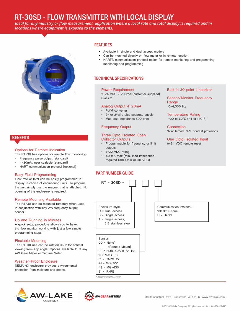
Options for Remote IndicationThe RT-30 has options for remote flow monitoring:• Frequency pulse output (standard)• 4-20mA, user scalable (standard)• HART communication protocol (optional)
Easy Field ProgrammingFlow rate or total can be easily programmed to display in choice of engineering units. To program the unit simply use the magnet that is attached. No opening of the enclosure is required.
Remote Mounting AvailableThe RT-30 can be mounted remotely when used in conjunction with any AW frequency output sensor.
Up and Running in Minutes A quick setup procedure allows you to have the flow monitor working with just a few simple programming steps.
Flexiable MountingThe RT-30 unit can be rotated 360° for optimal viewing from any angle. Options available to fit any AW Gear Meter or Turbine Meter.
Weather-Proof EnclosureNEMA 4X enclosure provides environmental protection from moisture and debris.
BENEFITS
Built in 30 point Linearizer
Sensor/Monitor Frequency Range 0-4,500 Hz
Temperature Rating -20 to 60°C (-4 to 140°F)
Connection3/4” female NPT conduit provisions
One Opto-Isolated Input9-24 VDC remote reset
Power Requirement9-24 VDC / 200mA (customer supplied) Class 2
Analog Output 4-20mA• PWM converter• 3- or 2-wire plus separate supply• Max load impedance 500 ohm
Frequency Output
Three Opto-Isolated Open-Collector Outputs: • Programmable for frequency or limit
outputs• 5-30 VDC rating • 40 mA max (min. load impedance
required 600 Ohm @ 30 VDC)
RT-30SD - FLOW TRANSMITTER WITH LOCAL DISPLAYIdeal for any industry or flow measurement application where a local rate and total display is required and in locations where equipment is exposed to the elements.
TECHNICAL SPECIFICATIONS
* Requires external sensor
PART NUMBER GUIDE
RT - 30SD -
Communication Protocol:“blank” = noneH = Hart®
Sensor:00 = None* (Remote Mount)02 = HUB-40SD1-S5-H211 = MAG-PB31 = CAPM-1541 = MG-30042 = MG-45081 = IR-PB
Enclosure style:D = Dual accessS = Single accessT = Single access, 316 stainless steel
FEATURES:• Available in single and dual access models• Can be mounted directly on flow meter or in remote location• HART® communication protocol option for remote monitoring and programming
monitoring and programming
FEATURES
©2015 AW-Lake Company. All rights reserved. Doc ID:RT30SDDS15
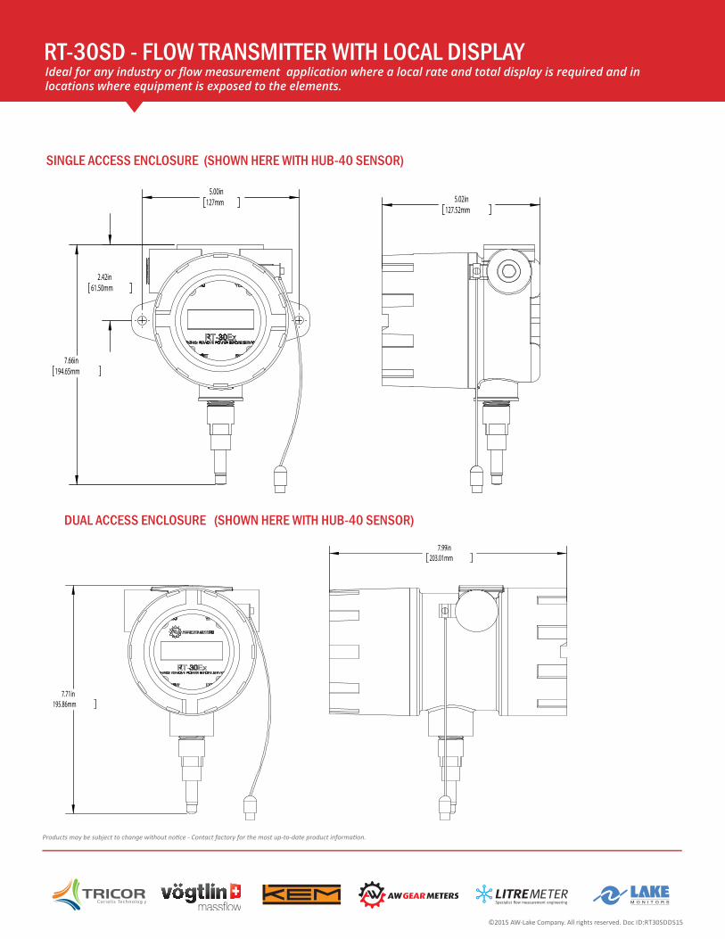
RT-30SD - FLOW TRANSMITTER WITH LOCAL DISPLAYIdeal for any industry or flow measurement application where a local rate and total display is required and in locations where equipment is exposed to the elements.
SINGLE ACCESS ENCLOSURE (SHOWN HERE WITH HUB-40 SENSOR)
DUAL ACCESS ENCLOSURE (SHOWN HERE WITH HUB-40 SENSOR)
Products may be subject to change without notice - Contact factory for the most up-to-date product information.
©2015 AW-Lake Company. All rights reserved. Doc ID:RT30SDDS15
BA
A
8809 Industrial DriveFranksville, WI 53126
Phone: (262) 884-9800Fax: (262) 884-9810
DRAWING NO.:PART NO.:UPPER LEVEL:DESCRIPTION:
MATERIAL:MODELED BY:DRAWN BY:REVISION:SCALE: 1:4
SIZE:
SHEET: 1 OF 1
DATE: 1/22/2015DATE: 10/14/2015
N/A
ImperialUNITS:TOLERANCES UNLESS OTHERWISE NOTED
IMPERIAL.XXXX ā .0005
.XXX ā .003.XX ā .01
FRAC. ā .015ANG. ā .5 Ā
SURFACE FINISH: 64 MAX
METRIC
SURFACE FINISH: 64 MAX
.XXX ā .013.XX ā .07
.X ā .25
ANG. ā .5 Ā
THIS PRINT, INCLUDING THE INFORMATION CONTAINED IN IT ISTHE PROPERTY OF AW-LAKE COMPANY. IT IS CONSIDERED
PROPPRIETARY IN NATURE AND MAY NOT BE USED ORDISCLOSED OUTSIDE OF AW-LAKE COMPANY, EXCEPT UNDER
PRIOR WRITTEN AGREEMENT. ANY MODIFICATIONS MADE TOOR COMMENTS WRITTEN ON THIS DRAWING BY
UNAUTHORIZED PERSONNEL WILL VOID THIS DRAWING. ALLDIMENSIONS SHOWN ARE SUBJECT TO CHANGE WITHOUT
NOTICE.
INTERNAL USE ONLY
THIRD ANGLE
REV. DESCRIPTION DATE BY ECN APVDREVISIONS
A 01/18/2013 XX XXX XX
7.71in195.86mm
7.99in203.01mm
BA
A
8809 Industrial DriveFranksville, WI 53126
Phone: (262) 884-9800Fax: (262) 884-9810
DRAWING NO.:PART NO.:UPPER LEVEL:DESCRIPTION:
MATERIAL:MODELED BY:DRAWN BY:REVISION:SCALE: 1:4
SIZE:
SHEET: 1 OF 1
RT-30-SD-S11RT-30-SD-S11
DATE: 10/14/2015DATE: 10/14/2015T.Binninger
N/A
UNITS:TOLERANCES UNLESS OTHERWISE NOTED
IMPERIAL.XXXX ā .0005
.XXX ā .003.XX ā .01
FRAC. ā .015ANG. ā .5 Ā
SURFACE FINISH: 64 MAX
METRIC
SURFACE FINISH: 64 MAX
.XXX ā .013.XX ā .07
.X ā .25
ANG. ā .5 Ā
THIS PRINT, INCLUDING THE INFORMATION CONTAINED IN IT ISTHE PROPERTY OF AW-LAKE COMPANY. IT IS CONSIDERED
PROPPRIETARY IN NATURE AND MAY NOT BE USED ORDISCLOSED OUTSIDE OF AW-LAKE COMPANY, EXCEPT UNDER
PRIOR WRITTEN AGREEMENT. ANY MODIFICATIONS MADE TOOR COMMENTS WRITTEN ON THIS DRAWING BY
UNAUTHORIZED PERSONNEL WILL VOID THIS DRAWING. ALLDIMENSIONS SHOWN ARE SUBJECT TO CHANGE WITHOUT
NOTICE.
INTERNAL USE ONLY
THIRD ANGLE
REV. DESCRIPTION DATE BY ECN APVDREVISIONS
A 01/18/2013 XX XXX XX
7.66in194.65mm
5.00in127mm
2.42in61.50mm
5.02in127.52mm

8809 Industrial Drive, Franksville, WI 53126 | www.aw-lake.comCOMPANY
Easy Field ProgrammingFlow rate or total can be easily programmed to display in choice of engineering units. To program the unit simply use the magnet that is attached. No opening of the enclosure is required.
Options for Remote IndicationThe RT-30EX has options for remote flow monitoring:• Frequency pulse output (standard)• 4-20mA, user scalable (standard)• HART communication protocol (optional)
Remote Mounting AvailableThe RT-30EX can be mounted remotely when used with the HUB-40EX sensor or HUB-41EX.
Up and Running in Minutes Easy thread-in installation. A quick setup procedure allows you to have the flow monitor working with just a few simple programming steps.
Flexible MountingBecause of the integral swivel union, the RT-30EX unit can be rotated 360° for optimal viewing from any angle. Options available to fit any AW Gear Meter or Turbine Meter. Spring loaded sensor eliminates damage of mechanical design.
Weather-Proof EnclosureNEMA 4X enclosure provides environmental protection from moisture and debris.
BENEFITSSensor/Monitor Frequency Range 0-4,500 Hz
Connection3/4” female NPT conduit provisions
One Opto-Isolated Input9-24 VDC remote reset
cCSAus Certification• Class I, Div. I, Groups C, D• Class II, Div. I, Groups E, F, G• Class III
ATEX CertificationII 2 G, Ex d IIB+H
2 T5 Gb,
Ta = -40°C to +60°C
IECEx CertificationEx d IIB+H
2 T5 Gb
Ta = -40°C to +60°C
Power Requirement: 9-24 VDC / 200mA (customer supplied) Class 2
Analog Output 4-20mA3- or 2-wire plus separate supplyMax load impedance 500 ohm
Frequency Output
Three Opto-Isolated Open-Collector Outputs• Frequency or limit outputs• 5-30 VDC rating • 40 mA max (min. load impedance
required 600 Ohm @ 30 VDC)
Built in 30 point Linearizer
Temperature Rating -20 to 60°C (-4 to 140°F)
RT-30EX - HAZARDOUS AREA RATED FLOW TRANSMITTERIdeal for any industry or flow measurement application where an explosion-proof local rate & total display is required, such as in offshore chemical injection, hydraulic fracturing, or industrial paint spray booths.
TECHNICAL SPECIFICATIONS
FEATURES • Choose from Hazardous area certification options including: cCSAus, IECEx or ATEX
• HART® communication protocol option for remote monitoring and programming.
• For use with most meter sizes of the following AW-Lake flow meters:- JVM-xxx-EX gear meters- JVS-xxx-EX gear meters- JVHS-xxx-EX gear meters- ZHM-xxx-EX gear meters- HPM-xxx-EX turbine meters - HM-xxx-AC-EX turbine meters- TRG-xxx-EX turbine meters
©2015 AW-Lake Company. All rights reserved. Doc ID:RT30EXDS15
PART NUMBER GUIDE
RT–30EX–
Communication Protocol“blank” = none H = Hart®
Sensor00 = None* (Remote Mount)01 = HUB-40EX sensor with CSA/cUS hazardous area certification04 = HUB-41EX sensor with ATEX and IECEx hazardous area certification
Enclosure StyleD = Dual accessS = Single access
*Requires approved remote mount sensor from AW-Lake

BA
A
8809 Industrial DriveFranksville, WI 53126
Phone: (262) 884-9800Fax: (262) 884-9810
DRAWING NO.:PART NO.:UPPER LEVEL:DESCRIPTION:
MATERIAL:MODELED BY:DRAWN BY:REVISION:SCALE: 1:4
SIZE:
SHEET: 1 OF 1
DATE: 9/25/2015DATE: 9/25/2015
N/A
ImperialUNITS:TOLERANCES UNLESS OTHERWISE NOTED
IMPERIAL.XXXX ā .0005
.XXX ā .003.XX ā .01
FRAC. ā .015ANG. ā .5 Ā
SURFACE FINISH: 64 MAX
METRIC
SURFACE FINISH: 64 MAX
.XXX ā .013.XX ā .07
.X ā .25
ANG. ā .5 Ā
THIS PRINT, INCLUDING THE INFORMATION CONTAINED IN IT ISTHE PROPERTY OF AW-LAKE COMPANY. IT IS CONSIDERED
PROPPRIETARY IN NATURE AND MAY NOT BE USED ORDISCLOSED OUTSIDE OF AW-LAKE COMPANY, EXCEPT UNDER
PRIOR WRITTEN AGREEMENT. ANY MODIFICATIONS MADE TOOR COMMENTS WRITTEN ON THIS DRAWING BY
UNAUTHORIZED PERSONNEL WILL VOID THIS DRAWING. ALLDIMENSIONS SHOWN ARE SUBJECT TO CHANGE WITHOUT
NOTICE.
INTERNAL USE ONLY
THIRD ANGLE
REVISIONSREV. DESCRIPTION DATE BY ECN APVD
A 01/18/2013 XX XXX XX
.9in22mm
8.7in219.93mm
8.0in203.01mm
2.4in[60.96mm]
BA
A
8809 Industrial DriveFranksville, WI 53126
Phone: (262) 884-9800Fax: (262) 884-9810
DRAWING NO.:PART NO.:UPPER LEVEL:DESCRIPTION:
MATERIAL:MODELED BY:DRAWN BY:REVISION:SCALE: 1:4
SIZE:
SHEET: 1 OF 1
DATE: 1/23/2014DATE: 9/25/2015
Material <not speci�ed>
ImperialUNITS:TOLERANCES UNLESS OTHERWISE NOTED
IMPERIAL.XXXX ā .0005
.XXX ā .003.XX ā .01
FRAC. ā .015ANG. ā .5 Ā
SURFACE FINISH: 64 MAX
METRIC
SURFACE FINISH: 64 MAX
.XXX ā .013.XX ā .07
.X ā .25
ANG. ā .5 Ā
THIS PRINT, INCLUDING THE INFORMATION CONTAINED IN IT ISTHE PROPERTY OF AW-LAKE COMPANY. IT IS CONSIDERED
PROPPRIETARY IN NATURE AND MAY NOT BE USED ORDISCLOSED OUTSIDE OF AW-LAKE COMPANY, EXCEPT UNDER
PRIOR WRITTEN AGREEMENT. ANY MODIFICATIONS MADE TOOR COMMENTS WRITTEN ON THIS DRAWING BY
UNAUTHORIZED PERSONNEL WILL VOID THIS DRAWING. ALLDIMENSIONS SHOWN ARE SUBJECT TO CHANGE WITHOUT
NOTICE.
INTERNAL USE ONLY
THIRD ANGLE
REVISIONSREV. DESCRIPTION DATE BY ECN APVD
A 01/18/2013 XX XXX XX
.8in21.50mm
8.8in223.10mm
2.4in61.50mm
5.0in127.52mm
1.5in37.80mm
RT-30EX - FLOW TRANSMITTER WITH LOCAL DISPLAYIdeal for any industry or flow measurement application where a local rate and total display is required and in locations where equipment is exposed to the elements.
DUAL ACCESS ENCLOSURE (SHOWN HERE WITH HUB-41 SENSOR)
Products may be subject to change without notice - Contact factory for the most up-to-date product information.
©2015 AW-Lake Company. All rights reserved. Doc ID:RT30EXDS15
ATEX/IECEx VERSION
cCSAus VERSION
SINGLE ACCESS ENCLOSURE (SHOWN HERE WITH HUB-40 SENSOR)
(1.5” cCSAus)
(2.4” ATEX)

8809 Industrial Drive, Franksville, WI 53126 | www.aw-lake.comCOMPANY
Monitoring Versatility The MX 9000 is available with one or two channels, to monitor:• Flow rate from one or two meters• Flow volume (sum or difference of two flows)• Ratio (product A/product B)
Customizable Housing OptionsThe MX 9000 is available in custom enclosures to meet your application requirements.
Easy Remote ProgrammingThis unit can be easily programmed to display what you need in a variety of engineering units.
Up and Running in MinutesEasy plug-in installation. A quick setup procedure allows you to have the flow monitor working with just a few simple programming steps.
BENEFITS
Frequency Inputs0-4 KHz, sine, square or saw-tooth; 4 volts minimum amplitude; 3.3 Kohm maximum impedance.
Integrated Linearization Maximum 30-point linearization table for improved accuracy over range.
Flow Sensor Power Supplies (2) @ 15 VDC / up to 50 mA each
Power Requirement14 to 16 VAC/250mA, or 18-24 VDC/200mA (customer supplied), or 120/240 VAC (optional).
*All units are shipped wit 120VAC/1000mA wall transformer.
Analog Output 4-20mAExternal-powered loop output into a maximum 500 ohm load impedance with 24 VDC supply. 2nd loop output optional.
MX-9000 PROCESS MONITORIdeal for any industrial flow measurement application where a simple, compact & easy-to-use remote flow monitor is required.
TECHNICAL SPECIFICATIONS
FEATURESRate, total, limit, batch and ratio options• Single or dual channel• Two programmable Form C relay outputs (optional)• One or two assignable 4-20 mA output (optional)• Easy-to-read LCD display with color backlight that changes color for warning or alarm• Batch controller - stores up to 20 batch recipes
APPLICATIONSThe MX 9000 Process Monitor is a versatile, multi-functional device that helps you track rate, total, limit, ratio, and more. Standard unit is one channel. Optional two channels allow you to monitor dual flows, and display them in a number of ways: separately, as a sum (for example in total material use), as a difference (as in fuel consumption), or as a ratio of product A/product B. Also use the MX 9000 to detect bi-directional flow when A and B channel signals are available from a single flow meter.
The MX 9000 has a number of related functions that add to its capabilities. Four model variations (see reverse side) give the MX 9000 the capability of performing limit, warning and alarm duties.
MX 9 – –
Output4 = 4-20mA outputX = No output
CommunicationX = No addl options
Main BoardS = Single channel flow/totalD = Dual channel flow/totalR = Ratio monitorB = Batch controller
Option Boards1 = 4-20mA out, Analog in, Frequency out, 2 relay out2 = 120/240VAC supply, 4-20mA out, 2 relay out, Frequency out, 3 = only for batch controllerX = No option board
PART NUMBER GUIDE
©2015 AW-Lake Company. All rights reserved. Doc ID:MX9000DS15

MX-9000 PROCESS MONITORIdeal for any industrial flow measurement application where a simple, compact & easy-to-use remote flow monitor is required.
Products may be subject to change without notice - Contact factory for the most up-to-date product information.
TERMINAL ASSIGNMENTS
Option board
MONITOR DIMENSIONS
Terminal Upper Connector Lower Connector
1 +18-24VDC/16VAC
2 DC COM/16VAC
3 +15VDC Out
4 Sig. 1 In
5 Sig. 1 Common
6 +15VDC Out
7 Sig. 2 In
8 Sig. 2 Common
9 EXT Reset +
10 EXT Reset -
11 I + Out 1
12 I - Out 2
OPTIO
N BO
ARD
DEPE
NDEN
T
Option board
Main board
©2015 AW-Lake Company. All rights reserved. Doc ID:MX9000DS15