com Installation, Care and Operation of Circuit Breakers ... · Installation, Care and Operation of...
66
_-.·· ... � Installation, Care and Operation of Circuit Breakers and Accessories ?25 R CI�IT BR BOOK E6426 These instructions are not intended to cover all details or variations that may be encotered in connection with the installation, operation, and maintenance of this equipment. Should additional information be desired contact the Allis-Chalmers Mfg. Company. llliS·(HllM IRS M F6. (0. BOSTON WORKS • BOSTON · MASS. I i l i www . ElectricalPartManuals . com
Transcript of com Installation, Care and Operation of Circuit Breakers ... · Installation, Care and Operation of...

_-.;.:..·· .....
� Installation, Care and Operation
of Circuit Breakers and Accessories
TYPE LA?25 .AIR CI�CUIT BREAKER
BOOK EWX.-6426
These instructions are not intended to cover all details or variations that may be encountered in connection with the installation, operation, and maintenance of this equipment. Should additional information be desired contact the Allis-Chalmers Mfg. Company.
llliS·(HllM IRS M F6. (0. BOSTON WORKS • BOSTON · MASS.
I i l
i
www . El
ectric
alPar
tMan
uals
. com

.I ..
)
www . El
ectric
alPar
tMan
uals
. com

• I -!1.' .
... l ·,
. ' .. AUIS·CHALMERS � MAIUFACTURIIG COMPAIY PROCEDURE FOR CHANGING COILS IN TRIP UNITS
ON LA-25 AND LA-5 0 AIR C IRCUIT BREAKERS UP THROUGH 6 00 AMPS
1. Loosen shoulder screw (1-1) located on the bottom of handle (l-2) and then slide the handle from the shaft.
2. Remove the screws which hold the shroud in place·and then slide off shroud.
3 • Loosen slotted screws (1-3) on top of operating frame and remove the front barrier and arc chute�� 4· · Remove hex head socket screw� (1-4) which connect the leads of the trip coil to the lower c�ntact block (l-5) on the right hand outside phase only.
5 · Detach the three hex hea� socket screws (3-1) located on molded piece in back of lower contact block in the right outside phase.
6 . Rotate the complete movable contact member (l-6) of the outside phase, until there is enough clearance to slide this section from the shaft.
7• Detach the hex head socket screws (2-1) which connect the trip coil leads to the lower contact blo�ks on the remaining
� two phases.
8. Remove the four assembly mounting bolts (3-2) which hold the ba•e plate, upon which the three phases of the trip device are mounted to the fra�e. 9· Detach the four mounting screws (4-1) which hold the core assembly in place and lift the complete core assembly ( 4-2) out of the trip device. Slide the coil (4-3) off the leg of the core and replace with new coil.
10. The device can be reassembled by reversing the preceding steps. Care must be taken to insure that the two .lower mounting screws holding the core in the assembly next to the armature shaft be securely tightened before the top two scre�s.
11. STANDARD TOOLS: All the tools used were standard and the following are recommended:
(A} Universal joint (1/4" drive )
(B ) 12" Extension Bar (1/4" drive)
(C) 3/16" Hex Head Bit for Universal joint (1/4" drive )
(D) 3/16" Allen Head Wrench
www . El
ectric
alPar
tMan
uals
. com

• ....
www . El
ectric
alPar
tMan
uals
. com
... .. . .. , .• ) ;·
f . . . '; \ ALLIS·CHALMERS � MANUFACTURING COMPANY
Figure 3
Series Overcurrent Trip Device for LA-25 Air Circuit Breaker, Upper Front View , Series Coil Mounted in Left Phase.
Rear View of LA-25 Air Circuit Breaker
Figure 4 www . El
ectric
alPar
tMan
uals
. com

:;.•, ., , • f
If J. "-, "i
-�
www . El
ectric
alPar
tMan
uals
. com
... . \. .
' ' ALLIS·CHALMERS � MANUFACTURING COMPANY
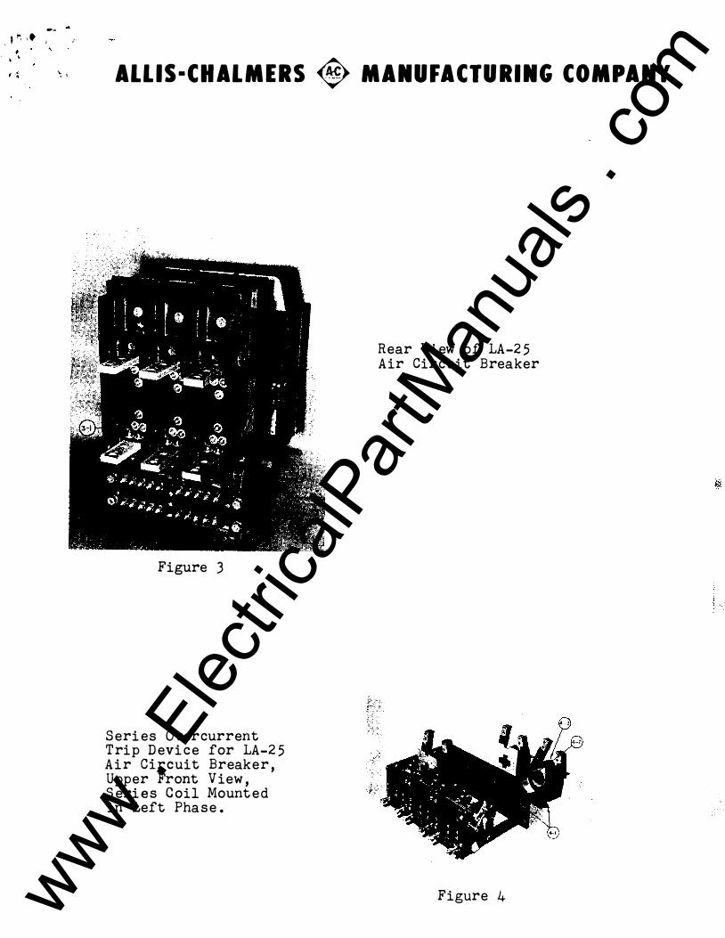
_t�'igure 1
LA-25 Air Circuit Breaker Showing A c cess to Middle Phase and Removal of Screws Holding Series Trip Coil in Place .
LA-25 Air Circuit Breaker with Arc Chut es , Phase Barriers Front Barrier Plate, and Shroud Removed.
Figure 2 www . El
ectric
alPar
tMan
uals
. com

. '
) .
�·.-�'<U �·
www . El
ectric
alPar
tMan
uals
. com

·'·-.
� , ALLIS·CHALMERS � MANUFACTURING COMPANY PROCEDURE FOR CHANGING COILS IN TRIP UNITS
ON LA-25 AND LA-5 0 AIR CIRCUIT BREAKERS UP THROUGH 6 00 AMPS
1 . Loosen shoulder screw (1-1) located on the bottom of handle (l-2 ) and then slide the handle from the shaft.
2. Remove the screws which hold the shroud in place-and then slide off shroud.
3· Loosen slotted screws (1-3) on top of operating frame and remove the front barrier and arc chutes.
4· · Remove hex head socket screws ( 1 -4 ) which connect the leads of the trip coil to the lower contact block (l-5 ) on the right hand outside phase only.
5 · Detach the three hex head socket screws (3-1) located on molded piece in back of lower contact bloek in the right outside phase.
6. Rotate the complete movable contact member ( l-6 ) of the outside phase, until there is enough clearance to slide this section from the shaft.
7• Detach the hex head socket s crews (2-l ) which connect the· trip coil leads to the lower contact blocks on the remaining two phases.
B. Remove the four assembly mounting bolts (3-2 ) which hold the ba�e plate, upon which the three phas e s of the trip device are mounted to the !ra�e. 9· Detach the four mounting screws ( 4-1) which hold the core as sembly in place and lift the complete core a s s embly (4-2 ) out of the trip device. Slide the coil (4-3) off the leg of the core and replace with ne• coil.
1 0. The device can be reassembled by reversing the preceding steps . Care must be taken to insure that the two lower mounting s crews holding the core in the ass embly next to the armature shaft be s ecurely tightened before the top two s cre�s. ·
11. STANDARD TOOLS: All the tools used were"s tandard and the following are recommended :
(A) Universal j oint (1/4" drive ) ( B ) 12" Extension Bar (1/4" drive ) (C) 3/16" Hex Head Bit for Universal j oint (1/4" drive ) (D) 3/16" Allen Head Wrench
www . El
ectric
alPar
tMan
uals
. com

www . El
ectric
alPar
tMan
uals
. com

�:�· �: 6 I- -TIME DELAY DEVICE (SECTION SHOWN ROTATED
90° FROM TRUE POSITION FOR CLAR ITY)
5 )--BELLCRANK
FIG. 18 TYPICAL UNDERVOL TAGE TRIP DEVICE JUNE 3,1955 71-440-031
9 }--TRIP BLOCK
... ... ... -"'
I "' = ... ... • ... • "'
.r • '
<$> • ... • c: ... ... "' ... c: • -• � "' 0 • .. ... • -c
..
. '
www . El
ectric
alPar
tMan
uals
. com

UNDER VOLTAGE TRIP DEVICE FOR TYPE LA-25
AIR CIR CUIT BREAKER
UNDERVOLTAGE TRIP DEVICE
' '
The undervoltage tri p attachmen t (Figo 18) provides a means for automatically tripping the breaker when t he voltage drops below a predetermined valueo The device consists essentially of a solenoid with a coil for the specified voltage» a positi ve displacement silic one oil time delay device (which f unctions the same a s tho se described under Part V - Protective devices) and ne cessary linkage for tripping the breakero This device is set at the factory to pick up and seal in if line voltage is 80% of normal voltage or above and wi ll d rop out if line voltage drops to some value between 30 and 60% of normal line voltageo
The undervolt age t ri p d evice (Fig o 18) is sh own in the energi zed positi on and func tions to trip the breaker in the following manner -The energy produced by c oil (18-1) of solenoid assembly (15-2) holds armature (lB-13) firmly against its pole head and this armature through b el l c rank (18-5) preloads springs (lB-3) and (18-4) o Whe n a drop in vol tage occurs (below a predetermined v alue), the force exerted on a bell c rank by the spring s over come s the magnetic attraction on the a rmature causing th e arma ttr e to leave the pole head and trip the breakero The breaker is trifped b y hook assembly (18-7) engaging trip pin (18-8) on trip block 18-9) rotating this
,,' -,
block counterclockwise which acts to trip th e breaker as previously �.&�� described in Secti on III - A of the operating mechanism. The time delay device (18-6) is fastened t� bell crank (18-5) and acts to to control th a time in which the preloaded springs respond to trip the breaker. For those applicati ons in which instantaneous undervoltage tr.ip is required, t he time delay device (18-6) is omitted.
INSPECTION AND ADJUSTMENT
The undervoltage t rip device should be inspected prior to being put in service to s ee that all pack ing traces a re removed and that the armature ( 18-13- slides freely t o the breaker tri p position without bei ng energized. This device (with t ime delay) le aves the factory set at 2 seconds time delay, whe n the voltage drops to zero, unless otherwise specif ied. The time delay device is adjustable, but not calibrated, between 2o5 seconds and o5 seconds. This adjustment is obtained by loosening nut (18-10) and positioning time delay device (18-6) on bel l crank (18- 5) as show n in (Fig. 18). The pick up and drop settings can be adjusted by loosening locknut (18-11) and adjusting the pre-compression of spr i ngs (18-3 ) and (18-4) by turning adj usting nut (18-12) o
NOTE: After making this adjustrren t, a check should be made to see that the armature still seats f innly ori the pole head, otherwise the increased exciting current m ay cause the co il to overheato
Jan • 1957
Allis-Chalmers Mfg. Co. Bosto n Works Boston, Masso www .
Elec
tricalP
artM
anua
ls . c
om

-�4.i�;�
' . . '
(/) lLJ 1-:::> � � � lLJ � �
ALLIS·CHALMERS � MANUFACTURING COMPANY
40
30
20
10 9.0 8.0 7.0
6.0
5.0
4.0
3.0 \ \
2.0
1.0 .9
.8 ;r .6 .5 .4
.3
AMBIENT TEMPERATURE 25°C
\ \ \ \ \ \ 1\ \ \ f\ \ \
\ \\ \ \ �\
\ "" " "" � " ........ ........ ........ ....
'- ......... --
' 1'-r-. ......... -
�"'--r-.. 1'---1--
-
-
INSTANTANEOUS TRIP
SET AT 800 % TO 1200% NORMAL RATING UNLESS OTHERWISE SPECIFIED
CALIBRATION
120% SETTING
-100% SETTING
- 80°/oSETTING
.2S 80 100 200 300 400 600 800 1000
PERCENT NORMAL RATING
FIG. 17A TYPICAL TIME CURRENT CURVE
THERMAL TRIP DEVICE NOV 4,1955 71-240-179 www . El
ectric
alPar
tMan
uals
. com

' '
www . El
ectric
alPar
tMan
uals
. com

. '
ALLIS-CHALMERS � MANUFACTURING COMPANY
3 4 5 I 71110 20 30 40 IO 10 7011 I .I .7 .I .I 1
BREAKER RATING TIMES SCALE EQUALS CURRENT IN AMPERES
FIG. 16
"
SERIES OVERCURRENT TRIP CALIBRATION CURVES MARCH 4,1955 71-340-066 www .
Elec
tricalP
artM
anua
ls . c
om

www . El
ectric
alPar
tMan
uals
. com

�;j �-
. '
INSTRUCTIONS FOR THE INSTALLATION AND OPERATION
OF ALLIS-CHALMERS TYPE LA=25
LOW VOLTAGE AIR CIRCUIT BREAKER AND
AUXILIARY EQUIPMENT
PART I
GENERAL INFORMATION
A� Introductiono The type LA=25 air circuit breaker is one of a line of low voltage air breakers which may be used in metal enclosed switchgear, on open type switchboards, or separately mounted in individual housings. The LA-2� air circuit breaker has an interrupting capacity of 25,000 amperes and a maximum continuous current rating of 600 amperes at 600 volts, 60 cycles. For information on other frequencies, the factory should be consultedo All LA-21 breakers are completely assembled, tested, and calibrated at the factory in a vertical position and must be so installed to operate properlyo Customer.s primary connections should be adequately braced against the effects of short circuit currents t� prevent overstressing the breaker terminals.
Bo Warrantyo Allis=Chalmers LA=21 air circuit breakers are warranted to be free of defects in material and workmanship for a period of one year after delivery to the origi�al purchaser. This warranty is limited to the furnishing of any part which to our satisfaction has been proven defectivec Allis Chalmers will not in any case assume responsibility for allied equipment of any kindo
Co Receiving and Inspection for Damage. Each LA-!5 air citcuit breaker and its associated apparatus is carefully checked, inspected, and packed at the factory by workman experienced in the proper handling of electrical equipment. Immediately upon receipt of this equipment, carefully remove all packing traces and examine parts, checking them against the packing list and carefully noting any damages incurred in transito If such is disclosed, a damage claim should be filed at once with the transportation company and Allis=Chalmers notified. Keep instruction books and tags with the breakers.
D. Storage. When breakers are not to be put into immediate use, they should be carefully wrapped or covered to provide protection from plaster or concrete dust and other foreign mattero Abrasive dust in the breaker can cause excessive friction and rapid wear. Breakers should not be exposed to the action of corrosive gases and moistureo In areas of high humidity or temperature fluctuations, space heaters or the equivalent
www . El
ectric
alPar
tMan
uals
. com

should be provided . Circuit breakers should be handled carefully at all times . Shock or jars in rough handling can cause serious damage.
PART II INSTALLATION AND OPERATION
A . Mounting . The LA-2 5 air circuit breaker is completely adjusted, tested, and inspected at the factory before shipment and no additional adjustment should be neces sary when installing . However, a careful check should be made to be certain that shipment and storage ha s not resulted in damage or change of adjustment (See next paragraph ). Circuit breakers should b e installed in a clean, dry, well-ventilated place in which the atmosphere is free from destructive acid or alkali fumes . Mount open type breakers high enough to prevent injury to personnel either from circuit interruption or from moving parts during automatic opening of the breaker . Allow sufficient space to permit access for cleaning and inspection . Also allow a minimum clearance of one inch to an insulating barrier above the break er to prevent damage from arcing .
' I
B . Inspection . Before be ing placed in service the breaker should be given a final inspection to be certain that adjustments and connections have not loosened in shipment or handling . Before installing breaker , make certain it i s in the open position and that all packing traces have been removed (breaker is shipped blocked in the clos ed position ). After breaker is in position, close it manually to check proper functioning of the mechanism and contacts . (CAUTION� MAKE SURE CIRCUIT IS NOT ENERGIZED.) Breaker should operate smoothly with incr·easing re sistance until fully clos ed and latched . During the clos ing operation , obs erve that the contacts move freely without interference or rubbing between movable arcing contacts (2-24) and parts of the arc chute {2-21). Continue to close and obs erve that the arcing contacts (2-24) and {2-2 5 ) touch before the main contacts (2-34) and (2-33). Observe that when main contacts touch that there is a positive wiping action which will produce a clearance at the bottom of the contacts .
NOTE: - Refer to Part IV, Paragraph C , Maintenance Check List , for values of adjustments and settings .
Check to be sure that springs are not solidly compress ed. Arcing contact springs (2 -22) and main contact finger springs (2-32) and (2-37} in particular should have overtravel to insur e against hard closing and overstre ssing of the breaker parts .
BWX:-6426 -2-
' ·, www .
Elec
tricalP
artM
anua
ls . c
om

'·
Observe that the manual operating handle (2-13) returns from clos ed to neutral positions automatically by a ct i on of it s return spring (2-9).
Next open breaker by means of manua·l trip button {2-1) on front of breake r& The toggle linkage (2-53) will c ollaps e, the contacts will move to the open posit i on freely and rapidly and the closing me chanism will reset, ready for the next operal ion. Operating springs (2=4) assist in rapid opening of the contacts and actuate the resett ing of the closing mechanism&
C . Operating Me chanism Checke The operating mechani sm i s properly adjusted and t ested at the factory , and ordinarily there should b e no need for readjustment in the field . If , for s ome reason , the me chanism fa ils to lat ch in the closed position, check to be certain that all trip devices are reset and not interfering with the trip lat ch (2-43)o The trip lat ch should b e free t o return t o its latching positione If the trip lat ch is free and the me chanism still fails to lat ch , che ck to be certain that there are no binds or interferences in the mechanism and that all links and latches are fully reset. If breaker i s still unstable , t he trip latch reset spring (2-42) may be adjusted t o increase its reaction against the lat ch (refer t o Maintenance Che ck List , Part IV , Se cti on C). However, before changing any adjustments be certain that the trip lat ch engagement i s sufficient , as outlined in the maintenance che ck list .
D. Trip Units and Accessory Devices. These it ems also � should receive a thorough che ck prior t o placing breaker in ._. s ervic e t o b e c ertain that adjustments are proper and parts are
not damagede Refer to Part s V and VI of the instruct ion book for the description of adjustment s and functions of these devices.
E. Pantograph and Trip Interloc k Adjustment. This applies only t o cubicle mount ed breakers of the drawout type . As a clos ed breaker is racked into position it should trip shortly after it passes the "test position" indicator. At this point the control cir cuit s will be made, but the primary connect ions will b e open , and i t will be impos sible to close the breake r until it reaches the "operating positi on" indicator. Continue· racking breaker in and close it when the operat ing position i s reached . Closing should not be affe cted by the int erlock meqp�n�. sm. Then, as the clos ed breaker is racked out towards the. t ,es·t ·position, after approximat ely 5/16 inches travel the bre�ke:r sl}ould trip . At this point , disconne ct fingers (1-14) will stil� be in full c ontact with the stati onary stud , and it will be .impos sible to close the breaker again unt il the test posit ion i s reached. If the me chanism does not function as described , refer t o the c ubicle instru ct ion book for corre ctive adjustment s .
BWX-6426 -3�
www . El
ectric
alPar
tMan
uals
. com

F. Energizing the Breaker. After complet ion of the installati on inspecti on , the breaker is ready to be energized. The breaker and its c ompartment should be clean and all foreign material removed. Control wiring should be checked and insulation tested. The drawout type breaker may be racked into pos it i on in th e cubicle and the stat ionary type may be mounted in its permanent locat i on . Once the breaker is energiz ed it should not be touched , except for operat ing , since most of the component parts are also energized.
PART III DESCRIPTION AND FUNCTION OF PARTS
A. Operating Mechani sm. Refer to Figs. 3 , 4 , 5. The operating mechanism transmits power from the solenoid operator or the manual clos ing lever to the contact structure to clos e the breaker. It is a trip free mechanism; that i s , the breaker contact s are free to open at any time if required , regardless of the posit i on of the mechanism or the force being applied to it. The manual and solenoid operators are exactly the same , differing only by the addition of an electrically operated solenoid ass embly and accessories.
Fig. 5 shows the breaker in the open positi on . Closing force is applied either by rotat ion of cam \12) through acti on o f manual clos ing lever ( 10) , or by act ion of sol enoid plunger (8). In either case, link ( 13) is rotat ed c ounterclockwis e about fixed c enter ( E) . The cam face on link {13) acts against cam roll ( 22 ) , moving it t o the right , and thus rotating link ( 14) clockwi se about temporarily fixed center ( D) . This act i on moves l ink ( 15) t o the right , thus clos ing breaker contacts ( 3) and ( 4) by clockwi se rotati on about fixed center ( F ) . When th e full closed positi on is reached , l ink (19) moves counterclockwise about t emporarily fixed c enter ( D) and locks link ( 13) in the operated pos iti on t o maintain the breaker closed as shown in Fig. 3. The sol enoi d plunger (or manual closing lever) may now return t o the neutral pos it ion.
Opening of the breaker contacts i s accomplish ed by the releasing of trip lat ch ( 5) . Refer t o Fig. 3. Trip lat ch (5) i s rotat ed clockwi se about center ( A ) by action of various trip devi ces or the manual trip button . Trip levers (6) and (7) are thus released and permitted to rotat e clockwis e about c enters (B) and ( C) respect ively. Temporarily fixed c enter (D) i s now released and free to move to the right , permitting the force of the stat ionary main conta ct springs , springs ( 2l)
i and springs ( 20) t o
move link ( 14} c ounterclockwise about cam rol ( 22 ) a s a c enter. Thus link ( 15) will move to the left and open the breaker contacts
BWX-642 6 -4-
www . El
ectric
alPar
tMan
uals
. com

(�) and (4). When the mechanism reaches the open position, l1nk (13) is released from link (19) and the mechanism is reset by spring (20) to the open position as shown in Fige 5o
Fig. 4 shows the mechanism in the trip-free positione Since latch (5) and levers (6) and (7) are released� center ( D) is not temporarily held as in a normal closing operationo Thus when link (13) rotates counterclockwise, spring reaction holds center (23) fixed and link (14) rotates counterclockwise about center (23). Thus, although link (13) goes through its complete stroke, link (15) does not move and the breaker contacts will not close. This action can take place during any part of the closing stroke, causing contacts to immediately return to the open position even though the solenoid remains energized or the manual closing stroke is completed.
B. Contacts� The contacts on the LA-25 breaker consist of main current carry1ng contacts and arcing contacts. They are arranged such that contact make and break is by means of the arcing contacts, while the main contacts are not subjected to arcing. Arcing contact surfaces are clad with a silver tungsten arcing alloy which greatly reduces mechanical wear and arc erosione The positive wiping action of the arcing contacts, as well as the properties of the contact material9 prevents welding and sticking when interrupting high currentso This insures long satisfactory service.
Another feature of the contact structure is the "blowon" effect produced by the physical configuration of the moving member. This is best shown schematically as in Figo 5· The current path, when main contacts only are parted, is from the arcing contact (5-3) to pivot point (I)� and thence completely around the loop of the main contact to pivot point (F)& The mechanical forces produced by current flowing in such a path tend to hold the arcing contacts solidly in contact, both in opening and in closing, and thereby prevent premature or uncontrolled contact parting or bounce� Both the stationary and the movable arc ing contacts have arc runners which lead the arc away from the contact surfacesQ This prolongs contact life as well as aiding arc interruption�
The main current carrying contacts are silver plated for good conductivity over long periods of time� A positive wiping action also facilitates high conductivity and insures that the actual current carrying areas are maintained smooth and clean and free from pitting or hammeringo When the main contacts make, the first point of contact is at the lower end of contact finger (2-33)� Further motion causes this contact finger to rotate in its socket, causing the contact point to move up towards the "knee" of the contact� and separating the initial contact pointe
BWX-6426 -5-
www . El
ectric
alPar
tMan
uals
. com

Another set of fingers (2-51) similar to the stat i onary main fingers e liminates the need for a current carrying movable h inge joint . These fingers are always in contact and take no part in the operating sequence of the breaker . They too are silver plated and spring loaded to maintain a high conductivity at all t imes .
C . Method of Arc Interruption . When the breaker is called upon to interrupt a current, the ma in c ontact s (2-34) (2-33) s-e ·parat e, transfering t h e current to the arc ing contact s (2-24) (2-25) without arcing. The "blow-on" effect previously des�ribed h olds the arcing contacts sol idly in conta ct unt il the desired parting time. When the arcing contacts part an arc is drawn between the silver tungsten contact surfaces . Due t o the inherent magnetic and thermal effects of the arc, it will rapidly move upwards along the arc runners and into the arc chute (2-21 ) where it is extinguished . Each assembly consists of a double arc ing contact group, each group working in a s eparate chamber in the arc chuteo This permit s two parallel arcs to be dr�wn on each phase of the breaker9 thereby reducing the current densit y of each arc and making it easier to extinguish the arcs . The chambers in the arc chut e are so vented int o ea ch other as to provide a uniform dielectric condition in order for the arc to divide int o the two parallel paths . In addition to easing arc int erruption, the double contact arrangement aids in prolonging arcing contact longevity .
Do Relays . Relays are used on electrically operat ed breakers to c ontrol the closing power to the operating mechanism and t o pe rmit remote or automat i c operati on of the circuit breaker . Two relays are used. The X relay (l-4) is energi zed by the control swit ch, or other means, to connect the cl osing coil to the control power source . A ooal in contact prevents partial operat ion and insures that a closing operat ion will be carried t o complet i on even though the control swit ch may b e opened quickly . The Y relay (1-7) acts as a cut-orf relay to deenergize the X relay at the proper time . It is energized by the aa switch and seals in through the X s eal in contact and the control switch . (The aa switch (Fig. 10) is a me chanically operat ed contact which closes when the solenoid approaches the completi on of the closing strokeJ When the Y contacts close, the X relay and closing coil are deenergized, but the Y relay will remain energized as long as tne control swit ch is held clos ed. This prevents " pumping" or repeated att empts to clos e. The control swit ch must be opened before another closing attempt is possible . The closing coil and the X relay coil are designed for intermittent duty and must not be permitted t o remain energized any longer than is necessary to clos e the breaker. The XY relay scheme accomplishes this aut omati cally . Fig . (6) shows a typical wiring diagram . Although variations may be necessary, or other control .el ements added, t o suit a specific application, the basic XY relay arrangement will usually be as described.
BWX-6426 -6-
www . El
ectric
alPar
tMan
uals
. com

•, E. Trip Unit s and Accessory Devices. Description and
function of th e s e it ems are covered in Part s V and VI of th e instruction book .
PART IV MAINTENANCE, ADJUSTMENT, AND REPLAC.EMENT
A . General . Oc casional che cking and cleaning of the breaker will promot e long and troublefre e service . Oiling and greasing should be done with care becaus e ex c e s s oil and grease t end to coll e ct dirt which in time might make operation s luggi sh and aff e ct the dielectric strength of insul ating members . Always refer to th e instruction book before removing part s or changing adjustment s . A rech e ck of the installation inspection (Part I I)· during maint enan ce will indicat e the overa ll general condition of th e breaker .
B. Pe riodic Inspection . A periodic inspe ction and servi cing should be includ ea in the breaker maint enanc e routine . A s emi-annual inspe ction is usually sufficient, however, in cas e s where unfavorable atmospheric conditions exist, more frequent inspe ctions are recommended . In any case, the total number of breaker operat ions between s e rvicing should not exceed 1750 for th e LA-25 breake r . The maint enance cheek list (Se ction C) .will provide a ready and c onvenient guide to a th orough and understanding inspe ct ion of the breake r . S ervicing will be facilitated if a tag is attached to ea ch unit listing dat e, ope ration count er reading, dat e of next inspection, count er reading at next inspection, and servic eman's signature .
c. intenance Che ck List . The following it ems are list ed for c onven enc e in ma nta n ng the equipment in the best possible c ondition . By periodically checking and maintaining these items, t he breakers will provide t he c ontinued satisfa ctory service of which they are capable.
1 . Cleaning. R'emove all dust, dirt and foreign
mat erial . Wipe off exc e s s oil and grea s e . Wipe down insulation . Clean cam fac e s, lat ch rolls and lat ch faces . Make certain th at dirt or oxidized gre a s e is not interfering with moving part s .
2 . C onne ction� Check all hardware for tightne s s . Che ck for loos e wiring c onnections and broken or abraided insulation.
3. Conta cts . Che ck main c onta ct s for cleanliness and permanence of silver plating . (Main contacts should not be dre s s ed.) Check arcing contacts for· wear ,and arc erosion . Contacts should be repla ced if arcing alloy shows indications of wearing
BWX-6426 -?-
www . El
ectric
alPar
tMan
uals
. com

t hrough before next inspection . Arcing contacts should also be replaced if, with arcing contacts ( 2-24) and ( 2-25) just touching, a 1/8� dia . rod cannot be passed between stationary contact fingers {2-33) and movable main contact ( 2-34).
4 . Lub ri cation. Needle bearing are packed with a spe cial lubri cant and should need no further attent ion . Bearing pins and other sliding or rotat ing areas should be wiped with a light film of "Aero Lubriplate" (made by Fi sk Co. ). Lubri cation should not be applied excessively and must be kept off insulating members , as it may affect dielectri c ability and cannot be satisfactorily removed .
5 . Conta ct Adjustment . Arc ing contacts ( 2-24) ( 2-25) do not require adjustment . Main contacts ( 2-33) (2-34) are factory adjusted and should not require field adjustment unle ss parts have been disassembl ede Adjustment is obtained by use of shims (2-18) between the operator frame ( 2-15) and the breaker frame (2-26). Main c ontacts are in proper adjustme nt when there is a clearance of 1/64" to 1/16" between the bottom of the stationary main contact (2-33), and the face of the movable main contact (2-34 } , with the breaker full closed . All contact fingers (2-33} should be in contact at th e " knee" of the contact and open at the bottom . Be certain that there is-aftertravel in springs {2-32) with the breaker full closed .
6 . Arcing Contact Hinge Tension . Spring washers (2-57) should be compressed to a height of . 038" t . 002"as measured with feelers between washers ( 2-58) and flat side of arc ing contact (2-24) .
?. Trip Lat ch Adj ustment . Tri p lat ch {2-43) should have a tripping force of 2 to 3� oz . as measured at right angles t o a 3/4" radius ( pulling in line with the centerline of screw (2-41) will fulfill this condition ) . Force may be changed ·by positioning slotted end of spring ( 2-42) - clockwise to decrease tripping force, and count erclockwise to increase the tripping force .
Trip latch ( 2�43) engagement on secondary trip lever (2-44) roll should be 3/16".± 1/16"'· 11/Ieasurement is from the leading edge o:f t rip lat ch face to the line of contact on the lat ch face . Adjustment is obtained by positioning screw ( 2-41) to vary the angular posit ion of trip latch ( 2-43). Trip lat ch roll on s crew (2-41) may have up to 1/32 " clearance to trip block ( 2-48) as long as the trip latch engagement is maintained .
8. Manual Closing Lever Overtravel Stops . Two overtravel stop screws (2-12) are provided . The one to the right of manual closing cam {2-10) is set to stop the manual closing lever (-2-13} in its vertical position and is set visually . The left hand stop screw limits travel in the closed position and is set
BWX-6426 -8-
.. www .
Elec
tricalP
artM
anua
ls . c
om

. '
t o provide l/32" to l /16" clearance between prop latch {2-2) face and pin on main closing cam (2-5) when the hand closing cam {2-10) i s against the overtravel stop s crew.
9 . Reset Buttono The reset button (14-6) is adjusted to provi de l/16" to l/8" clearance between reset lever (14-10) on the breaker and trip devi ce reset lever (14-17) with the reset shaft (14-l) on the trip device in the tripped pos ition .
10 . Operat ion Count ero The ope ration counter (2-11) when supplied is actuated by the open-clos e indi cator (2-14) and is adjusted such that the counter arm ha s some overtravel when breaker is open .
11 . Limit Swit ch . With breaker in closed and lat ched position , the upper contacts (10-8) (10-9) of limit swit ch {10-3 ) should have l/3 2" follow-up after contact make . Adjustment i s by use of shims (10-7) between swit ch and mounting pad .
12 . Closing Solenoido The closing s olenoid (Fig . 9 ) i s mount ed on the operating mechanism frame (2-15) and pinned in posit ion . Should readjustment ever be necessary, the solenoi d i s t o b e positi oned and repinned such that with the solenoid armature (9-13) tight against the pole head (9-5) to hold the breaker clos ed, the main closing cam (9-1) will have l/8" clearance to its overtravel stop (9-10) , and the prop lat ch (9-6) face will have 1/16" clearance to the prop latch pin {9-7). After se curing the solenoid mounting s crews (9-4) , and drilling four letter "F" ( . 257" dia . ) holes for the locking pins (9-11) but before inserting pins , check breaker open position . There should be 1/32" to l/16" clearance between the end of the armature cam (9-8) and the cam pins {9-9). If adjustment is ne cessary, remove solenoid and rotate solenoid armature stop (9-14) as necessary and lock with set screws (9-15) , after which the solenoid is replaced on the breaker and pinned in place . Not e that redrilling for locking pins is not ne ces sary f or normal reassembly - only when adjustments require changing .
D . Movable Arcing Contact . The movable arc ing c ontact (2-24) may be replaced, after removing arc chut es (2-21) and phase barriers (2-20), by removing hardware and spring washers {2-57) at the h inge joint of the arc ing c ontact . In reassembling, make certain that the hinge tension is correct as outlined in S ection IV - C-6.
E. Stationary Arcing Contact . The stationary arcing contact (2-25) may be replaced, after removal of arc chut es and phase barriers, merely by removal of s crews (2-27) and (2-28) . Repla ceme nt i s obvious and no adjustment is required .
'
BWX-6426 -9-
www . El
ectric
alPar
tMan
uals
. com
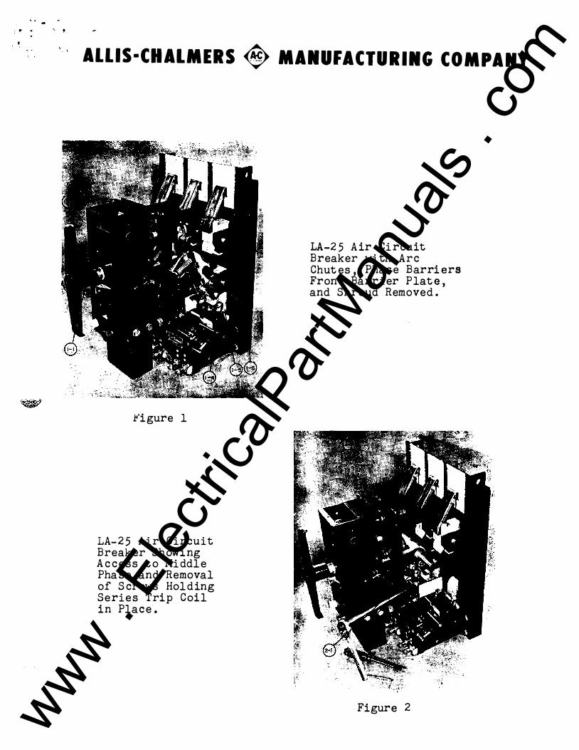
F . Movable Main Contact . Th e movable main c onta ct (2-34) i s best removed as a unit including the arcing contact . The out side c ontacts must be removed before the center phase conta ct can be removed . Contacts will be free for removal when the hinge pin i s removed. Since the hinge pin is under pres sure from t he hinge joint c ontact fingers (2-51) , care must be used not to s core or damage the pin. In replacing movable contacts be certain that all three phases are lined up on shaft (2-56) to insure smooth operat ion a nd freedom from binds .
G. Stati onary Main Contacts. To remove the lower main contact block (2-50), first remove movable contact assembly (2-34) as outlined in Part IV - F th en s crews (2 -49) and (2 -36 ). If desirable , c ontact block (2-50J and moving contact unit (2 -3 4 ) can be removed as a group on the outside phases . Then, after removing the main shaft (2 -56) , the center phase assembly can b e removed . To remove upper main contact block (2-30) , first remove movable main contact (2-34) as outlined in Part IV - F , then
' ' . . , -
s crews (2-3 1) and (2-27) , permitt ing contact block {2-30) and stationary �rcing contact (2-25) to be removed as a group . Once the above members are removed , it i s a s imple matter to replace contact fingers (2-33) and (2-51) . Remove fingers under a cloth or other shield t o prevent springs from flying free . A screwdriver may be used to work springs and fingers to the ends of th e block for removal. Be careful not to raise nicks or burrs or otherwise damage contact fingers. Not e that spring (2-37) c onsist s of a double (inner and out er) spring , while spring (2-32 ) i s a s ingle s pring . During reassembly o f upper and lower contact blocks there are no part i cular adjustments to observe , however , alignment between the three phases is important to insure that the � main operating shaft (2-56) is free of binds and that the complete � assembly works smoothly and easily.
H . Trip Units and Acces sory Devices . For maintenance , adjustment , and replacement of these devices refer to Parts V and VI of the instruction book, where detailed instruct i ons will b e found .
I . Operating Mechanism (Manual) . The manually operat ed me chanism i s fastened to the breaker panel frame by four�rews (2-17) . Shims (2-18) are us ed to adjust main contacts (see s ection IV-C-5) and must not be changed for any other reason . The operator may be removed from the breaker by disconnecting breaker operating l ink (2-52) and removing four s crews (2-17) , carefully noting amount of shims (2-18). Aft er reassembly , pay part i cular atte ntion t o trip lat ch adjustments and �a in contact adjustments t o b e certain thP.y have not changed. Check me chanisms for ease of operation and freedom from binds .
BWX-6426 -10-
www . El
ectric
alPar
tMan
uals
. com

'·
J. Operat ing Mechanism (Electrical) . The electri cal operat ing mechanism is exactly the same as the manual mechani sm with the addit i on of an electrical solenoid and accessori es to ' a c c omplish the closing operation . The manual closing means i s retained , a s i n the manually operated breaker . The operating mechanism and solenoid can be removed as a unit as described in sect i on IV - I, after disconnecting the clos ing coil and limit switch leads . Should the solenoid be removed from the operating mechanism , it must b e carefully readjust ed on assembly as out
lined in sect ion IV - Ccl2o A D.C . solenoid is furnished for use with a direct current control source. When the breaker i s to b e operated from an alternating current source , an A . C . solenoid i s furnished . Thus , rect ifiers and aging resistors are not required .
. K. Clos ing Coil. Removal of the closing coil (9-16) requires that the solenoid (Fig. 9) be removed from the breaker . Thi s i s ac complished by removing locking pins (9-11) and s crews (9-4). With the solenoid removed, the armature stop (9-14) can be removed , (aft er marking it for replacement at th e same setting) , permitting the a rmature to be withdrawn and the coil removed . After replacing coil, mount and adjust solenoid as outlined in section IV - C-12, making sure that all connections are made up tight .
PART V PROTECTIVE DEVICES
and Calibrat on . eries overcurrent trip devi ces us e on ow voltage breakers function to trip the breaker whenever the current through the breaker exceeds a predetermined value . Thi s devi ce includes a series coil , magneti c c ircuit with two armatures, and a sealed oil time delay devi c e . This arrangement is varied somewhat on current ratings above 600 amps. on the LA-50, and the LA-75 breakers , in that the trip device coil i s not t ied to the lower contact structure , but is linked to an inductive series coil mounted on the fixed bus in the rear of the breaker. Figure 12 showe the arrangement of the funct ional components of this device and Figures 15 , 16 give the inverse time delay characteristics .
The trip elements available in the various categori es of series trip devices are three in number and calibrated in the following rangeso
Long time delay element - for us e in combinat ion with the adjustable instantaneous trip and/or th e short t ime delay element . The pick up of the long t ime d elay element i s · · adjustable in the field to SO, 100, 120, 140 , or 160% pi ckup of the
BWX-6426 -11-www . El
ectric
alPar
tMan
uals
. com

c ontinuous current rating of the trip coil� Calibrati on settings in excess of 100% do not permit the cont i nuous current rati ng t o exceed 100% of the series coil rat ing .
Short t ime delay element - for use in c ombi nation with the adjustable instantaneous eleme nt and/or the long t ime delay element on sele ct ive trip syst ems. The pickup of the short time delay e lement is adjustable in the field to 500 , 750 and 1000% pickup of the cont inuous current rating of the trip coi l .
Instantaneous trip element - for use in combinat i on with the l ong and short time delay elements. The pi ckup of the i nstantaneous trip element is adjustable in the field betwee n 500 and 1500% pi ckup of the continuous current rating o f the trip coil .
The series overcurrent tri p devi ces are factory adjusted and calibrated and should not be disturbed in the field without proper equipme nt and knowledge of the device . The operation of the long t ime delay element(l2-l� is as follows: When the magnet i c pull on the armature(l2-15)increases suffic iently due to an overcurrent condition in the series coil( l2-� , the armature (12-1� will pick up and rotate about shaft (l2-4� This magnet i c attraction must overcome the tension i n th e pickup spring( l2-20 ) and also displace the silicone oil in time delay device(l2-14) from the lower chamber to the upper chamber through the accurately controlled metering element (12-12). As the armature closes the ·
gap t o the core �2-�, it engages tri p block(2-4�and trips the breaker. When the breaker has trippe d , the armature will reset against stop(l2-lO) due to t ension in pick up spring. Qui ck reset � is provid ed by means of the check valve (12-13)in t i me delay device .
The short t ime delay element(l2-18)functions in the same manner as the long time element . The one major difference betwee n the two elements is that the short t ime delay devic e U2-19) has a c oarser metering element. The time delay devic es for th e long and short t ime delay elements are not int erchangeable and are clearly marked in that the cover on the long t ime delay device is red and the short t i me delay devic e is green.
The time delay band adjustments for the two inverse time elements are adjustable by locat ing the plunger(l2-l)of the time delay devic e i n th e proper mount ing hole as marked on the ��tensions of the trip elements. To decrease t ime ban� move plunger locat ion closer to shaft ( 12-4) of armature and t o increase move plunger away from shaft . This relocati on of th e plunger varies the force applied to the time delay qevice by changing the lever arm and also changing the stroke require d for tripping . Each time band , maximum , int ermediate or minimum , is marked by a whit e band indicat ing the mounting poin� for the t ime delay devi ce plunger. All of the band locat ions are
BWX-6426 -12-
www . El
ectric
alPar
tMan
uals
. com

'·
progressive and if des ired , intermediate settings may be made between the cal ibrated points for finer selectivity&
The pi cku� calibration of the armatures i s selecte d by rotating knob (12-2 ) which moves the cal ibration label (12-3) t o the required setting . Adjustment of the calibrati on label i ncrease s or decrease s tension in the p ickup spring and is factory calibrated for values- of pi ckup currento
INSPECTION AND ADJUSTMENT
The series trip device should be inspected prior t o being put in service to see that the pickup calibration and t ime delay band selections are in accordance with the application requirements. �his device l eaves the factory with the following standard settings unless otherwise specified in the purchase order: Long time delay element i s s et at 100% p ickup on the int ermediat e t ime delay band. Short time delay element i s s et at 750% p i c kup on the int ermediate time delay bando Instantaneous trip element is set at $00% p ickup . Sele ctions other than those already made to the device do not require further testing in that the unit i s completely calibrated at the factory . The current rat ing of the seri es coil i s stamped on the break er Nameplates and should be che cked in appli cat ions involving vari ed current ratings.
MAINTENANCE AND REPLACEMENT
The individual phase series trip devi c e assemblies are mounted on a common base and must be removed from the breaker for maintenance or repla cement as one as semblyo To remove thi s assembly, detach the assembly mounting bolts {2-39) , and s crews, {2-47) and (2-49 ) holding the seri e s overcurrent coils (12-7) t o the contact structurec Having removed the assembly from the breaker,each single phase assembly can t hen be detached from the common base by the removal of four mount ing s crews (14-15) and the reset shaft (14-1).
To remove seri es coil (12-7) whi ch doe s not require a s ingle phase disassembly , detach the four mounting s crews (12-5) holding cor e assembly (12-$ ) in place and sl ide the complet e core a ssembly out of th e device . The series coil will then slide off the core leg and can be assembled in the reverse steps . Care must be taken at assembly that the two s crews (12-5) holding the c ore in the assembly next to the armature shaft (12-4) be s ecurely t ightened before the other two s crewso
To remove t ime delay devices (12-14) or (19) remove e ither side plate from the s ingle phase assembly , detach the.time delay d evic e plunger (12-1) from the trip armature and sli de the devi ce
BWX-6426 -13-
www . El
ectric
alPar
tMan
uals
. com
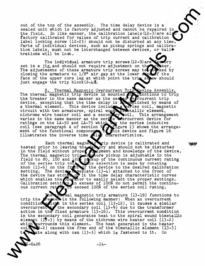
out of the top of the as sembly. The time delay devi ce is a sealed unit whi ch i s factory adjusted and cannot be repaired in the field . In like manner, the calibration labels (12- 3)are also factory calibrated for values of trip current and calibrat ion label locking s crew (12-25) should not be di sturbed at any t ime. Parts of individual devi ces, such as pi ckup springs and calibration labels, must not be int erchanged between devices, or calibrat ions will be lo st.
The individual armature trip screws (12-9)are fact ory set in a jig, and should not require adjustm.ent on the br-eaker. The adjustments of these armature trip s crews may be che cked by clos ing the armature to 1/8" air gap at the lower edge of th e face of the upper core leg at whi ch point the trip s crew should just engage the trip block(2-4�.
B. Thermal Magn eti c Overcurrent Trip Devic e Assembly. The thermal magneti c trip device is mounted and funct ions t o trip t.he ·breaker in the same manner as the series overcurrent trip devi c e, excepting that the time delay is accomplished by means of a thermal element. This devi ce includes a series c oil, magnet i c c ircuit with two armatures, spiral wound bimetallic element , n ichrome wire heater coil and a secondary coil. Thi s arrangement varies in the same manner as the series overcurrent devic e for rat ings on the LA-50 and LA-75 which use the series inductive c oil lsee paragraph A of section V). Figure 13 shows the arrangement of the functional components of this device and figu re 16 illustrates the inverse time delay characteri st i cs.
Each thermal magnet ic trip devic e i s calibrate d and � tested prior to leaving the factory and should not be disturbed in the field without proper equipment and knowledge of the devic e. The thermal magnet i c triP. armature pi ckup is adjustable in the field t o 80 , 100 and 120% pickup of the cont inuous current rating of the se rie s trip coil. This se le ction is made by rotating knob (13-6) on the front of the devi ce t o the desired calibrati on setting . The devi ce nameplate (13-4) attached t o the front of the d evi c e has et ched on it the time delay characteristi c curves which enables the operat or to easily select the proper sett ings. Calibrat i on settings in excess of 100% do not permit the continuous current rating t o exceed 100% of the series coil rat ing.
The thermal magneti c trip armature (13-19) functions t o trip t h e breaker i n the following manner: When an overcurrent c ondit ion exi sts in th e serie s coil (13- 12) , it causes a s imilar overcurrent in the s e condary coil (13-9) due t o the transformer· a ct ion in the fixed armature (13-16). This ·overcurrent conditi on in the secondary coil generat es heat t o the spiral wound b imetallic element (13-3) by means of the nichrome wire heater coil (13-2) whi ch surrounds this element. The heat generat ed in the h eater c oil (13-2) causes the free end of the bimetallic element (13-3) t o rotate along with cam (13- 5) whi ch is fastened to it. On
BWX-6426 -14-
www . El
ectric
alPar
tMan
uals
. com
1. 2. 3. 4. 5. 6. 7. B. 9.
10. ll. 12 . 13. 14. 15. 16. 17. 18. 19. 20.
AlliS·CHALMERS � MAIUFACTURIIG COMPANY
SECTION "A-A"
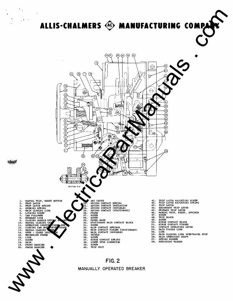
MANUAL TRIP, RESET BUTTON 21. ARC CHUTE PROP LATCH 22. ARCING CONTACT SPRING PROP LATCH SPRING 23. ARCING CONTACT INSULATION OPENING SPRING 24. ARCING CONTACT (MOVABLE) MAIN CLOSING LINK 25. ARCING CONTACT (STATIONARY) LOCKING SCREW 26. FRAME CAM FOLLOWER 27. SCREW BREAKER LOCK 28. SCREW CLOSING HANDLE RETURN SPRING 29. PANEL BASE MANUAL CLOSING CAM 30. STATIONARY MAIN CONTACT BLOCK OPERATION COUNTER (WHEN REQ'D) 31. SCREW CLOSING CAM OVERTRAVEL STOPS 32. MAIN CONTACT SPRINGS MANUAL CLOSING LEVER 33. MAIN CONTACT FINGER (STATIONARY) OPEN - CLOSE INDICATOR 34. MAIN CONTACT (MOVABLE) MECHANISM FRAME 35. SHIELD LINK 36. SCREW SCREW 37. HINGE CONTACT SPRING SHIM 38. LOWER STUD CONNECTOR FRONT BARRIER 39. SCREW PHASE BARRIER 40. TRIP UNIT
FIG. 2 MANUALLY OPERATED BREAKER
41. TRIP LATCH ADJUSTING SCREW 42. TRIP LATCH ADJUSTING SPRING 43. TRIP LATCH 44. SECONDARY TRIP LEVER 45. PRIMARY TRIP LEVER 46. MANUAL TRIP, RESET, SPRINGS 47. SCREW 48. TRIP BLOCK 49. SCREW 50. HINGE CONTACT BLOCK 51. HINGE CONTACT FINGER 52. CONTACT OPERATING LEVER 53. MAIN TOGGLE LINK 54. LINK 55. MAIN CLOSING LINK OVERTRAVEL STOP 56. MAIN OPERATING SHAFT 57. SPRING WASHER 58. RETAINING WASHER
www . El
ectric
alPar
tMan
uals
. com

www . El
ectric
alPar
tMan
uals
. com

[;, ' ·�'
M A NUA L
(/(--(f) STAT I O N A R Y \U A R C I N G C O NTACT
/j; lt · -- F I X E D C E N T E R
Q-- MOVA B L E C E N T E R
@-- CAM R O L L
C L O S I N G L E V E R 00:
P O SITIO N I N D I C ATOR
S O L E N O I D (§ P L UN G E R
\ CLOSE D POS IT ION
F I G - 3
4) MOVABLE
T R I P F R E E POSITION F I G - 4
I � \.1� S TAT IONARY
MAIN C O N TACT
MAIN C O N TA C T
SCHE MAT I C D I A G R A M O F TYPE'' L�' OPE RATI NG MECHA N I S M
A
/(! \u
/ p-? , {J l_,;
0. �·� F \ \Y
\ � T RI P LAT C H TO TR I P
O P E N POS I T I O N F I G - 5
a. ,_ ,_ -"'
I � :I: a. ... • ... • "'
� • a. • c: ... a. � ... c: • -• en � 0 • .. a. • -<
www . El
ectric
alPar
tMan
uals
. com

' .
www . El
ectric
alPar
tMan
uals
. com

' .
ALLIS·CHALMERS � MANUFACTURING COMPANY
INSTANTANEOUS ARMATURE I TH��fU�IP_ I 9
THERMAL ARMAT SPRING
��J.!sNG·- 15
THERMAL MAGNETIC OVERCURRENT TRIP DEVICE
FIG. 13
4 ··ARMATURE STOP
---+--J I
,.l
www . El
ectric
alPar
tMan
uals
. com

, , '
www . El
ectric
alPar
tMan
uals
. com

' . ,•
200
too •• ..
••
ALLIS-CHALMERS � MANUFACTURING COMPANY
, , , , , ,
A DJ U STABLE CALI BRATED P I C KUP
ADJU STABLE CALIBRATED PICK U P
T Y P I C A L
h+-+++t---'-4-+,--+c-f--++++1---++-+++'--+1 TIME CURRENT CHARACTER ISTIC lt=t+m:=Jt:+��l+t::ttl :: t:tn:tt=iftsEE1:UlEnt=tl DUAL MAGNETIC TRIP DEV I CE
1=-1'-'�+-++t---++h-'-+-r.+"++++ll-+·++++-�• • LOWER BAND L1 M I T DENOTES f'-+*-+-H-"--.,.+-J-,..;.,.-+S-1-+-++-+�-'+-+-+++'-� 1 RES E TTAB LE Tl M E D E L AY
UPPER BAND L I M IT DEN O T E S TOTAL BREAK E R T R I P T I M E
1!9!'lf+t+-.,.f+tJ-,-?tf'+t+++HI++'++1f+-'-"� I AMBIENT TEMPERAT U R E
BREAKER RATING TIMES SCALE EQUALS CURREN T I N AMPERES
F IG. I 5 SERIES OVERCURRENT TRIP CALI BRAT I ON CURVES M ARCH 4 , 1 95 5 7 1 - 34 0 - 06 5 www . El
ectric
alPar
tMan
uals
. com

www . El
ectric
alPar
tMan
uals
. com

RESET SHAFT--{ I
FLAG RELEASE SPRING-·{ 3
14 1--0VERCURRENT TRIP DEVICE ASSEMBLY
15 }--MOUNTING SCREWS
2 1 }--FLAG RELEASE SHAFT
---
--l ---1 :
7 J 1 l
------/ 0 o �----------J I __ ____ -2_}----------J
FIG. 14 I N DI CATOR F L AG, M ECHANICAL LOCKOUT, B E L L ALARM SWITCH
Be RE S ET B U T TON F O R OVERCU R R EN T TRI P DEVICES
.. ,.. ,.. -
� I ""
= .. ,.. • ... • �
� • .. • c: ... .. "" ... c: • -• � "" 0 • .. .. • -<
www . El
ectric
alPar
tMan
uals
. com

, '
www . El
ectric
alPar
tMan
uals
. com

ALLIS·CHALMERS <8> MANUFACTURING COMPANY
r - - - - - - - - - - - - - -- - - - - - - - - - - - - - - - �- -
-r_, "--0---o:::n-------r-T;s------- -r� s L s I T c T L C T T
lLI I I 1 I o J.. a ,l 1 r - - -, I � @ � : 0 I � I (J) A '2 L - -1
X I .,J
7
b �2
r T Y P I C A L W I R I N G D I A G R A M FO R
E L E C T R I C A L L Y O P E R A T E D B R E A K E R S
F I G . 6 A
I r ill I A.C. B. - - - I
4 5 I I 12 1 3 14 15 1 11 1 11 1 1!DJCJO'JbJap 9 10 16 17 18 19 20
I�fa� � I TC I S E R I E S liJ -� T R I P C O I L S
T Y P I C A L W I R I N G D I A G R A M FO R
M A N U A L L Y O P E R A T E D B R E A K E R S
F I G . 6 8
www . El
ectric
alPar
tMan
uals
. com

www . El
ectric
alPar
tMan
uals
. com
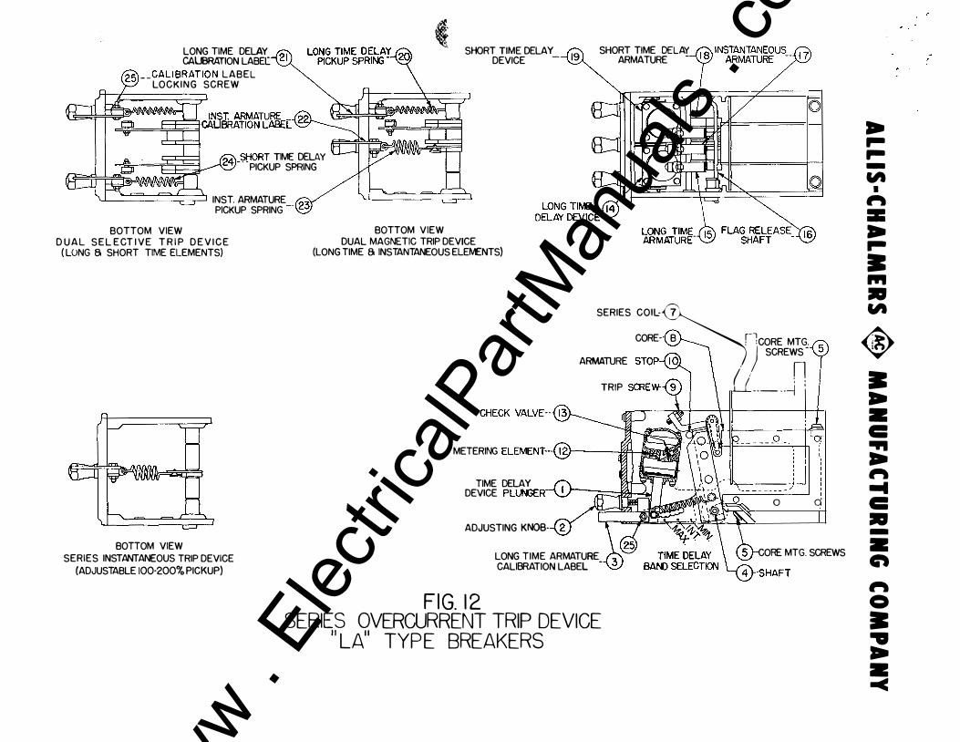
LONG TIME DELAY -{21 CALIBRATION LASE[ 25) - - CALIBRAT ION LABEL
LOCKING SCREW
24)_$tiORT TIME DELAY PICKUP SPRING
I \, c==') c==) I \ \ ( I I INST. ARMATURE (23" PICKUP SPRING --
BOTTOM VIEW
�
BOTTOM VIEW
SHORT TIME DELAY -{ 19 DEVICE - SHORT TIME DELAY ARMATURE
0
D U A L S E L E CT I VE T R I P D E V I C E ( LONG 6 SHORT TIME ELEMENTS)
DUAL MAGNETIC TRIP DEVICE (LONG TIME 6 INSTANTANEOUS ELEMENTS)
BOTTOM VIEW SERIES INSTANTANEOUS TRIP DEVICE
(ADJUSTABLE 100-200% PICKUP)
SERIES COIL:� CORE- B r ·iCORE MTG.
A�E STOP-� . ) 11 SCREWS -
U( : : TRIP SCREW-( 9 ) I \ _ - - - --j
METERING ELEMENT---( 1 2) :Et'i 1
TIME DELAY DEVICE PLUNGER-"W- � _]J ADJUSTING KNOB-
F I G. 1 2
LONG TIME ARMATURE CALIBRATION LABEL -
SERIES OVERCURRENT TRIP DEVICE '' LA" TYPE BREAKERS
: I
____ jj :::__j :
0 d
CORE MTG. SCREWS
.. ,_ ,_ -
"' I
fl\ = .. ,_ • ... • "'
� • .. • c: ... ... fl\ .... c: • -
• C\ fl\ 0 • .. ... • -<
www . El
ectric
alPar
tMan
uals
. com

www . El
ectric
alPar
tMan
uals
. com
l . t '
ALLIS·CHALMERS � MANUFACTURING COMPANY
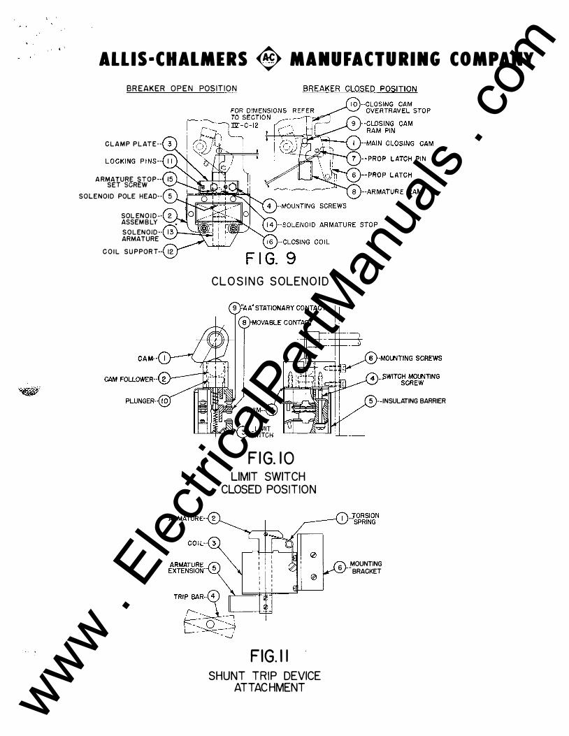
BR EAKER O P E N POSIT ION
C L A M P P L AT E--
A RMATURE S T O P -- 15 SET SCREW
SOLENOID POLE HEAD-- 5
SOL EN O I D -- 2 ASSEM B LY
S O L ENOID-· ARMATURE
C O I L S U P POR T-- 12
C L O S I N G S OLEN O I D
F IG. I O LIMIT SWITCH
CLOSED POSITION
FIG. I I SHUNT TRIP DEVICE
ATTAC HMENT
5 --INSULATING BARRIER
6 _MOUNTING BRACKET
www . El
ectric
alPar
tMan
uals
. com

I J I J www .
Elec
tricalP
artM
anua
ls . c
om

, • '
ALLIS-CHALMERS � MANUFACTURING COMPANY
AUXILIARY SWITCH
F IG. 7
CONTACT FINGE
SPRIN
TERMI NAL
SECONDARY B
__ __ _ _ _]
SECONDARY DISCONNECT ASSEMBLY
F IG .8 www . El
ectric
alPar
tMan
uals
. com

• , www .
Elec
tricalP
artM
anua
ls . c
om

. ' '
overloads , the rotation of cam (13 -5)i s suffici ent to release the thermal trip armature (13 - 19 ) which was previously restrained by roller ( 13 -7) working against this cam . Upon being released , the thermal armature rotates on shaft ( 13 - 10) so as to c lose the air gap through whi ch it i s electromagnetically attracted t o the ·core assembly l l3 - 13 ). As the thermal armature ( 13 -19 ) close s thi s gap , it picks up and engages the trip block ( 2-4S ) at trip screw ( 13 -14) and a cts to trip the breaker as previously described i n · section III - A of the operating mechanism . The breaker having tripped , the core assembly (13 -13 ) is no longer energi z ed whi ch al�o�s the th ermal arma t ur e to be returned to its latched position by r�turn spring (13 -18 ). A short time int erval may be required t o �ompletely reset cam ( 13 - 5 ) after trip cycle is completed due t� �ooling of bimetallic element.
Because of the inherent long time delay of this device i'\i is equipped with an instantaneous trip armature ( 13 -21 ) which provides high-overload protection . This instantaneous trip ar�ature is factory set so as to trip the breaker wh enever there i s an overload of 8 t o 12 t imes normal coil current .
Trip screw (13 -14) on the rmal trip armature ( 13 -19 ) i s · removed for those appl icat ions whi ch require the th e rmal armature
t o s ound a bell alarm on overcurrent c ondit i ons , but not trip the breaker. Under the s e c ondit i ons the instantaneous . trip armature ( 13 -21 ) must have the trip screw ( 13 -14 ) properly adjuated for h igh ove rloa d prot e cti on . For d etai ls c oncerning reeet ot the b ell alarm see se ct i on VI - C und er bell alarm .
� I NS PECT ION AND ADJUSTMENT
The thermal magn et i c t ri p devi c e sh ould be inapected prior t o be ing put in servi ce in the aa=e manne r aa tht aeriea trip devi c e to che ck that th e pickup calibrat ion is in aocord&Aoe with the appli cat i on requirements . The ther111al trip devic e l•aves the fact ory wit h the following standard settings unl e s s otherwi se spe cified in the purchase order : ·
Th ermal magnet ic trip element is set at 10� pi ckup calibration , Instantaneous trip element is set at 800% pickup . The thermal magnet ic t
. rip eleme
.nt may· be 'ad
. justed with out . f'urt�er
t est ing as thi s element has been fa ctory calibrated over it s full :r;�nge ,· but the in stant aneous element would require calibration t o change it s pickup value D To ad just inst
.
antaneous pi q�up1 loosen screw ( 13 � 22 ) and increase t ens ion in pic kup spring t l3 -i0 ) t o incre a s e pi ckup and de crea_ s e t ension to de crease pickup by rotat ing bracket ( 13 -23 ) about lo oking s o rew ( l) wl7 )
BWX-6426 - 15-
www . El
ectric
alPar
tMan
uals
. com

MAINTENANCE AND RE PLACEMENT
The ind ividual pha s e thermal trip d evice a s s emblie s are mounted on a c ommon bas e and fastened to the breaker in th e s ame manner as the s eri e s trip device . This as s embly requires the s ame procedure for removal and series coil replacement as the s eries trip a s s embly e Refer to section V - A " Series trip Maintenance and Replacement" f or d etail instructions . Other parts of the d evice s hould not be removed or disas s embled since to d o s o will disturb the calibration .
C . Overcurrent Trip Flag Iadicator and Reset . Each phase of the series and thermal magnetic trip devices are equipped with flags that indicate which phas e or phases caused the tripping of the breaker due to overcurrent or short circuit conditions . These flags ( 14-7 ) are so arranged that as the trip armatures ( 14 -2 0 ) close the ga� on tripping , the armatures engage flag release shaft ( 14-21 ) which pivots about point "A" . The engagement of the flag shaft by the trip armature causes the s haft
' ' . ,
to move out from under the hook point "B" on the flag ( 14-7) and release s ame at the instant the breaker trips. The target rotate s in clockwise direction due to gravity and torsion spring ( 14-3 ) which in turn rotates the reset shaft ( 14-1 ) by means of pin ( 14 -2 ) . The pins ( 14-2 ) which rotate the reset shaft ( 14-1 ) are so located that only the phase or phases which caused the breaker to trip , release the flag . The flag is then visible at point "C" to the operator to indicate which phase caused the breaker to trip . To reset the flags , pus h reset button ( 14-6 ) , which actuates res et lever ( 14-7) to rotate reset shaft ( 14-1 ) � thereby resetting · · · ·
flags ( 14-7) at point "B" J providing that the ,overcurrent condi- ��� tion has been remov ed o
NOTE : The tripping of the flag on any phase of the trip device during tripping cycle does not lockout the breaker a s the breaker may be closed without resetting flag system .
PART VI
ACCESSORY ATTACHMENTS
A . Shunt Trip Attachment @ The shunt trip attachment Fig 6 11 is used to trip the breaker electrically from a remote position by closing its circuit either manually through a control switch or automatically through relay contacts . Since the shunt trip coil is designed for a momentary duty cycle g an "a" auxiliary contact switch is used to interrupt its circuit immediately after the breaker is tripped � Each electrically operated breaker is equipped with a shunt tripping device for remote control. This device is mounted on a bracket on the left side of the mechanism
BWX-6426 -16-
•
www . El
ectric
alPar
tMan
uals
. com

' 'frame as shown on Fig . 1 . It includes a coil , magnet , armatur e and return torsion springs . Energizati on o£ the coil (11-3 ) causes armature (11-2 ) t o pi ckup and engage trip bar (11-4 ) thereby tripping the breaker . The torsion springs (11-1 ) are used primarily to return t he armature to a neutral pos ition aft er the breaker trips . Little or no maintenance or a djustment i s required on thi s devi c e . To check , move the armature t o the pickup posit i on and note that the trip bar has moved the trip lat ch as explained in sect i on III paragraph A under operating mechanism .
B . Auxiliary Swit ch Attachment . The auoc iliary switch Figure 7 is of the rotary type and is sturdily c onstruct ed . This swit ch i s mount ed on the operat ing me chanism frame and funct ions by dire ct conne ct ion to the breaker me chanism . Ele ctrically operat ed breakers are provided wi.th 2 ·"a" and 2 " b" { 7-4 ) contacts in thi s swit ch , mount ed on the left side of the mechanism . Provisions are available for the mounting of an identi cal swit ch on the reverse side . "a" switches are closed when the break er contacts are closed , and "b" swit ches closed when breaker contacts are open . The auxiliary swit ch contacts are fact ory set for "a " and "b" posit ion , but may be int erchanged in the field by reass embling the rotor element (7-1) as desired . A moulded bakelite cover (7-3 ) which snaps on can be easily removed for contact inspect ion .
C . Bell Alarm Switch Attachment . The bell alarm swit ch (14-8 ) functions to close an alarm circuit upon automatic overcurrent tripping of the breaker , or by special appli cat ion may indicat e an overcurrent condit ion by sound ing an alarm without tripping the breaker . This switch is a s ingle pole double throw swit ch mount ed on the outer phase trip devic e . The bell alarm switch is a ctuat ed by lockout lever (14-9 ) whi ch rotat es with reset shaft (14-1 ). The rotation of the reset shaft is described under " series t rip flag indi cat ion" se ,ct ion V paragraph C. The rotat ion of lockout lever (14-9 ) trips toggle spring (14-16) whi ch holds this lever in the tripped position unt il reset butt on ( 14- 6) is actuated to reset the reset shaft . It must be not ed that the bell alarm swit ch is reset only by manually actuat ing the reset but t on ( 12 - 6 ) . Repla cement of the bell alarm swit ch requires only th e removal of two mounting s crews holding swit ch to the trip devic e . On reas sembly check t o be certain that alarm will sound when lockout lever (12 -9 ) is released .
D. Mechani cal Overcurrent Lockout Attachment . The mechani cal lockout feature prevents the circuit breaker from 'being closed e ither manual.ly or electri cally aft er being tripped by an overcurrent condit ion . This feature locks the trip me chanism in the trip free positi on and can be removed only by manually· res etting reset butt on .
BWX-6426 -17-
www . El
ectric
alPar
tMan
uals
. com

The mechani cal lockout Fig . 14 i s provided by adding lockout bar (14-18) to the breaker trip shaft (14-22) in th e mounting l ocat i on provided on this shaft (14-22) . When an overload has tripped the breaker and the reset shaft (14-1 ) on the trip devi c e , as described under " series trip flag indi cat ion" section V paragraph c , the me chani cal lockout bar (14-18) i s held in the tripped posit ion by lockout lever (14-9 ). Thi s l ever (14-9) as explained under section VI paragraph C i s held in the tripped position by t oggle spring (14-16) . This prevents the breaker trip lat ch (2-43) from resetting . S ince the brea ker is mechanically trip free , it cannot be clos ed by any means unt il the trip lat ch (2-43 ) i s reset by actuating the reset butt on (14-6) t o reset loc kout lever (14-9) .
February 1955
BWX-6426
Alli s-Chalmers Mfg . C ompany Boston Works Boston , Mass .
-18-
. ' www .
Elec
tricalP
artM
anua
ls . c
om
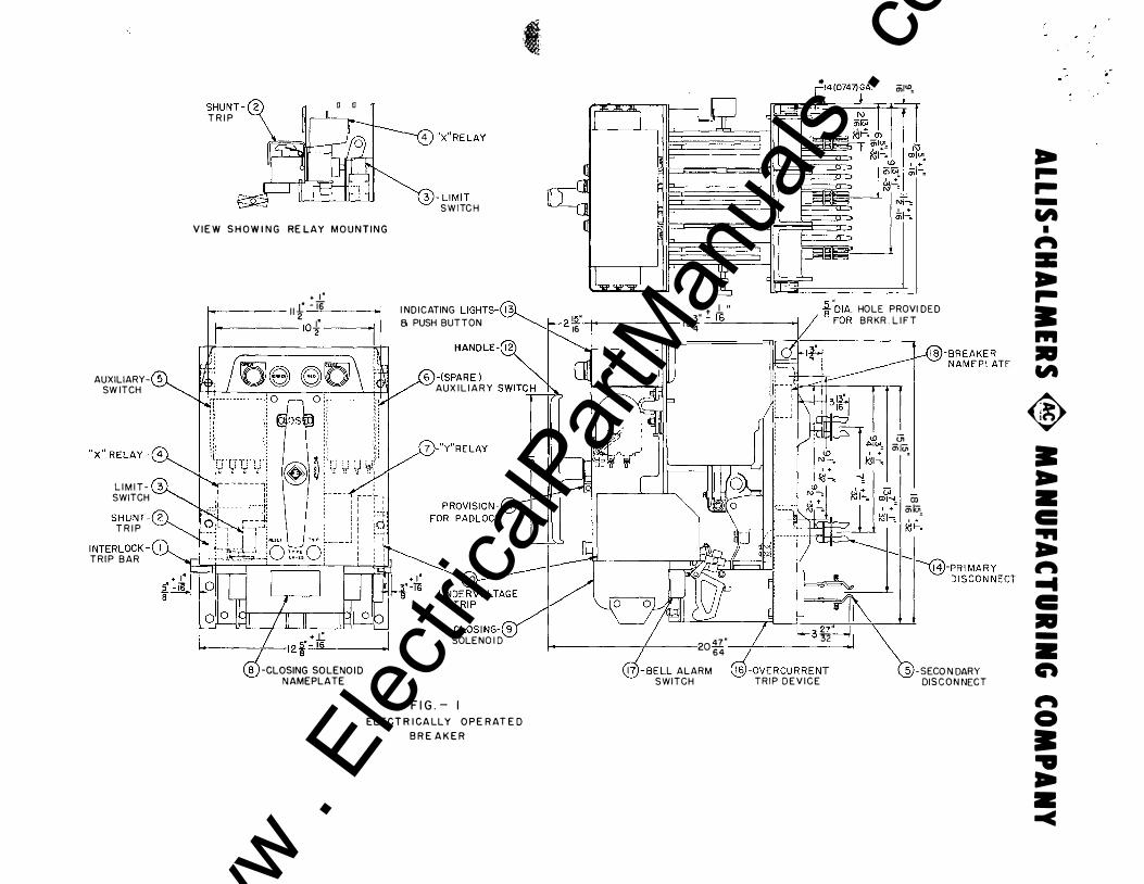
AUXILIARYSW ITCH
" x " R ELAY - (4
L I M I T SWITCH
SHUNT-f2 T R I P
INTERLOCK -(! TR IP BAR
SHUNT - ( 2 T R I P
c 0
4 )-"X"RELAY
3)- L IM IT SWITC H
----.. ; ,.
� �
... -\14 (0747)GA mi<D, I , � I
V I E W S H O W I N G RE LAY M O U N T I N G �
+ I '
1 1 f - TG -----
1of --
-CLOSING SO LENO I D N AMEPLATE
--1 IT I "='=="
I ND ICATING LIGHTS-(13}_ , " -t l " 8 PUSH BUTTON :;;r2 15 13� ---'-'l6"-----_..,
-rDIA. HOLE PROVI DED FOR BRKR . L I F T
HANDLE- 1 2
"'-- 16 4
6 )-(SPAR E ) '-11.1 IJ U) I I' �-AUX I L I A R Y swiTC H -..... t " r � - -� 1 , 1
7 )-"Y"RELAY
C LOSI NG-(9 SOLENO I D
F I G . - I E L E C T R I CA LLY O P E R AT E D
B R E A K E R
1,._3 27'� 1 47" I '32
_/ 20 64 -
@- BELL ALARM {§J-OVERCURRENT SWITCH TRIP DEV ICE
Ul mlu;,
Ol ml<:ii,
\ �i,fg��:i,
.. ... ... -"'
I � = .. .. • ... • "'
� • .. • c: ... .. � ... c: • -• en � 0 • .. .. • -<
.-
www . El
ectric
alPar
tMan
uals
. com

' .
' . .
www . El
ectric
alPar
tMan
uals
. com

"" t ' \ .... .
. . ' '
ALLIS·CHALMERS � MANUFACTURING COMPANY
LA-25 low vo ltage air c i rcu i t breaker 178&03
www . El
ectric
alPar
tMan
uals
. com

�
.. ' '
. . ' www .
Elec
tricalP
artM
anua
ls . c
om

' .
· ..
. ' ' . '
ALLIS-CHALMERS <8> MANUFACTURING COMPANY
INDEX TO INSTRUCTION BOOK COVERING
TYPE LA-2 5 AIR CIRCUIT BREAKER
C ont ent s
Part I . General Informat i on
A . Int roduct i on B . Warranty C . Receiv ing and Inspe cti on for Damage D . St orage
Part II . Installat ion and Operat ion
A . Mount ing B . · Inspection c . Operating Me chanism Che ck D . Trip Unit s and Accessory Devi c e s E . Pant ograph and Trip Int erl ock Adj ustme nt F . Energiz ing the Breaker
Part III , D e s cript i on and Funct i on of Parte
A , Operat ing Me chani sm B . C ontacts c. Method of Arc Interrupt ion D . Relays K. Trip Unit s and A ccessory Devi c es
Part IV . Maintenanc e , Adjus tment and R epla cement
A , General B. Peri odi c In spe ct i on C . Maint enance Che ck Li st D . Movabl e Arcing Conta ct E . Stat iona ry Arc ing Cont act F . Movable Ma in Cont a ct G . Stat ionary Main Conta ct H . Trip Unit s and A ccessory Devic e s I . Op erat ing Me chanism (Manual ) J . Op erat ing Me chanism ( El e ctri cal ) K . C losing Coil
BWX-642 6
Page No ,
l l l l
2 2 .3 .3 .3 4
4
g 6 7
7 7 7 9 9 10 10 10 10 ll ll
www . El
ectric
alPar
tMan
uals
. com

) �
., ...
' ' . . , ,
·�
www . El
ectric
alPar
tMan
uals
. com

. ·
' . .
...
ALLIS-CHALMERS � MANUFACTURING COMPANY
Cont ent s ( Cont ' d . } Page No .
Part V . Prot ective Devices
A . S eries Overcurrent Trip Device Assembly Adjustment and Calibration 11
Inspection and Adjustment 13 Maint enance and Replac ement 1 3
B . Thermal Magnet i c Overcurrent Trip Device Ass embly 1 4
Inspect ion and Adjustment 15 Ma int enance and Replacement 16
C . Over current Trip Flag Indicator and Reset 16 Part VI . Accessory Atta chments
A . Shunt Trip Attachment 1 6 B. Auxiliary Switch Attachment 17 c . Bell Alarm Swit ch Attachment 1 7 D . Me chani cal Overcurrent Lockout Attachment 17
BWX-6426 www . El
ectric
alPar
tMan
uals
. com

' .
:• ..
. ; �
www . El
ectric
alPar
tMan
uals
. com

. ·
�"
' ' .
3 '
ALLIS·CHALMERS � MANUFACTURING COMPANY
Figur e
1
2
4 , &
6
7
8
9 10
11
12
13
14
15
16
17
18
5
BWX.-6426
LIST OF I LLUS TRATI O NS COVERJNG ALLIS - CHALMERS T YPE IA-2 5
LOW VOLTAGE AIR C IRCU IT BREAKER AND AUXI LIAR Y EQUil?M.BN T
D e s c ri p ti on
El e ct r ic a l ly Ope ra t e d Break er
M an ua ll y Op e ra t ed B r e a ker
Op e ra t in g M e ch an ism ( S ch erm t i c ) W i ri .r:g D i a gr ams
Aux i l i a ry Swi t ch
S e conda r y Dis c on ne c t
Clo si ng S o len oi d
L imi t Sw it ch
Shun t Tr i p D evic e
S e rie s Tr ip D evic e
The rmal Tri p D ev ic e
Indi o at o r F la g , Me cha n i cal Lo ck ou t :, B el l Alarr:·, Sw i t ch , a n d Re s e t Bu t t on f or Over curr ent Tr i p Devi c e s
S e r ie s Tri p Cur v e s ( Dual M agn eti c ) S e r ie s Tr ip Curve s ( Dual S ele c t i v e ) The rmal Tr ip Cur ve s
Und erv ol t age Tr ip D evic e
www . El
ectric
alPar
tMan
uals
. com

. , i
' ' • , , .. , - #
www . El
ectric
alPar
tMan
uals
. com

. , I ' ' ..
ALLIS·CHALMERS � MANUFACTURING COMPANY
CAUT IONS TO BE OBSERVED IN THE I NSTALLATION AND OPERATI ON OF THE LA -2 5 AIR CIRCUIT BREAKER
1 . DO NOT ATTEMPT T O OPERATE BREAKER OR INSERT I N CUBICLE UNT IL ALL PACKING TRACES HAVE BEEN REMOVED . BREAKER IS SHI PPED LOCKED IN CLOSED POS IT ION .
2 . READ INSTRUCTION BOOK BEFORE MAKING ANY CHANGES OR ADJUSTMENTS ON T HE BREAKER .
3 . DO NOT INTERCEANGE PARTS OF TRIP DEVIC ES - TO DO SO MAY CHANGE CALIBRATIONS .
4 . ALWAYS OPERATE MANUAL CLOS ING HANDLE QUICKLY AND DEC IS IVELY - TO HES ITATE IN MIP-STROKE MAY CAUSE UNDUE BURNING O F CONTACTS .
5 . CHECK CURRENT RATI NGS AND SERIAL NUMBERS AGA I NST SINGLE LINE DIAGRAM TO ASSURE THAT BREAKERS ARE PROPERLY LOCATED IN SWITCHGEAR AT I NSTALLAT ION ,
BWI-6426 www . El
ectric
alPar
tMan
uals
. com

. , , -
,. ,
www . El
ectric
alPar
tMan
uals
. com

, ,.
•'
' . ��> ' I' ' ALLIS·CHALMERS � MANUFACTURING COMPANY
� .
PROCEDURE FOR CHANGING COILS IN TRIP UNITS ON LA-25 AND LA-5 0 AIR C IRCUIT
BREAKERS UP THROUGH 600 AMPS
1 . Loosen shoulder screw ( l-1) located on th e bottom of handle ( 1 -2 ) and then slide the handle from the shaft.
2 . Remove th e screws which hold the shroud in place - and then slide off shroud.
3 • Loosen slotted screws (l-3) on top of operating frame and remove the front barrier and arc chutes.
4 · · Remove hex head socket screws (l-4) which conn ect th e leads of the trip coil to the lower contact block ( l-5) on the right hand outside phase only.
5 · D etach the three hex head socket screws ( 3-l) located on molded pi ece in back of lower contact bl�ek in the right out side phase .
6 . Rotate the complete �ovable contact member ( l-6 ) of the outside phase, until there is enough clearance to slid e this secti on from the shaft .
7 . Detach the hex head socket s crews ( 2 -1 ) which connect the ·
trip coil leads to the lower contact blo cks on the remaining two phases.
8. Remove the four assembly mounting bolts ( 3-2) which hold the ba� e plate, up on which the thre e phases of the trip device are mounted to the frame. ' 1·
9 · Detach the four mounting screws ( 4-1) which hold the core a s s embly in place and lif t the complete core assembly ( 4-2) · · out of the trip device . Slide the coil ( 4-3 ) off the l eg of ' the c ore and replace with new coil .
10. The device can b e reas s embl ed by reversing the preceding s t eps . Care mus t b e taken to insure that the two lower mounting s crews holding the core in the ass embly next to the armature s haft be s ecurely tightened before the top two s cre�s . ·
• 11. STANDARD TOOLS : All the tools used were s tandard and the following are recommended :
{A) Universal j oint (1/4" drive ) ( B ) 12" Extension Bar (1/4" drive ) (C ) 3/16" Hex Head Bit for Universal j oint ( 1/4" drive )
,lf4&: ( D ) 3/16" Allen Head Wrench
www . El
ectric
alPar
tMan
uals
. com

, ,
•
• • \ ,.
, ,
_, . .... .
.. '
www . El
ectric
alPar
tMan
uals
. com