Color CCTV Camera - Panasonic Canada · Color CCTV Camera Operating Instructions. 2 ... Use only...
52
Before attempting to connect or operate this product, please read these instructions carefully and save this manual for future use. Model No. WV-CS564 Color CCTV Camera Operating Instructions
Transcript of Color CCTV Camera - Panasonic Canada · Color CCTV Camera Operating Instructions. 2 ... Use only...

Before attempting to connect or operate this product,please read these instructions carefully and save this manual for future use.
Model No. WV-CS564
Color CCTV CameraOperating Instructions

2
The serial number of this product may be found on thetop of the unit.You should note the serial number of this unit in thespace provided and retain this book as a permanentrecord of your purchase to aid identification in the eventof theft.
Model No.
Serial No.
WARNING:TO PREVENT FIRE OR ELECTRIC SHOCK HAZARD, DO NOT EXPOSE THIS APPLIANCE TO RAINOR MOISTURE.
The lightning flash with arrowhead sym-bol, within an equilateral triangle, isintended to alert the user to the pres-ence of uninsulated "dangerous volt-age" within the product's enclosure thatmay be of sufficient magnitude to con-stitute a risk of electric shock to per-sons.
The exclamation point within an equilat-eral triangle is intended to alert the userto the presence of important operatingand maintenance (servicing) instruc-tions in the literature accompanying theappliance.
CAUTION:TO REDUCE THE RISK OF ELECTRIC SHOCK,
DO NOT REMOVE COVER (OR BACK), NOUSER SERVICEABLE PARTS INSIDE.
REFER SERVICING TO QUALIFIED SERVICEPERSONNEL.
CAUTIONRISK OF ELECTRIC SHOCK
DO NOT OPEN
ENGLISH VERSION
NOTE: This equipment has been tested and found to com-ply with the limits for a Class A digital device, pursuant toPart 15 of the FCC Rules. These limits are designed toprovide reasonable protection against harmful interferencewhen the equipment is operated in a commercial environ-ment. This equipment generates, uses, and can radiateradio frequency energy and, if not installed and used inaccordance with the instruction manual, may cause harm-ful interference to radio communications.Operation of this equipment in a residential area is likely tocause harmful interference in which case the user will berequired to correct the interference at his own expense.
FCC Caution: To assure continued compliance, (example- use only shielded interface cables when connecting tocomputer or peripheral devices). Any changes or modifica-tions not expressly approved by the party responsible forcompliance could void the user’s authority to operate thisequipment.
For U.S.A
SA 1965
SA 1966

3
1) Read these instructions.
2) Keep these instructions.
3) Heed all warnings.
4) Follow all instructions.
5) Do not use this apparatus near water.
6) Clean only with dry cloth.
7) Do not block any ventilation openings. Install in accordance with the manufacturer's instructions.
8) Do not use near any heat sources such as radiators, heat registers, stoves or other apparatus (includ-ing amplifiers) that produce heat.
9) Do not defeat the safety purpose of the polarized or grounding-type plug. A polarized plug has twoblades with one wider than the other. A grounding-type plug has two blades and a third groundingprong. The wide blade or the third prong are provided for your safety. If the provided plug does not fitinto your outlet, consult an electrician for replacement of the obsolete outlet.
10) Protect the power cord from being walked on or pinched particularly at plugs, convenience recepta-cles and the points where they exit from the apparatus.
11) Only use attachments/accessories specified by the manufacturer.
12) Use only with the cart, stand, tripod, bracket or table specified by the manufacturer or sold with theapparatus. When a cart is used, use caution when moving the cart/apparatus combination to avoidinjury from tip-overs.
13) Unplug this apparatus during lightning storms or when unused for long periods of time.
14) Refer all servicing to qualified service personnel. Servicing is required when the apparatus has beendamaged in any way, such as power-supply cord or plug is damaged, liquid has been spilled orobjects fallen into the apparatus, the apparatus has been exposed to rain or moisture, does not oper-ate normally, or has been dropped.
S3125A
IMPORTANT SAFETY INSTRUCTIONS

4
• High quality picture of 768 x 494 pixels• Minimum illumination of 2 lx (at AGC High)• Protocol adaptability to Panasonic's protocol• A run of manual operations is memorized in
the patrol learn mode for repetitive use infuture.
• 32 preset positions
FEATURES
Panasonic presents highly advanced CCTV tech-nology that meets the demands of new and ever-changing applications.This high-performance color CCTV camera is uti-lized as a video surveillance device.
PREFACEThe camera incorporates the Digital SignalProcessor, pan-tilt mechanism, x18 zoom lensand RS485 communications in a compact enclo-sure.
• 360° panning at a rotation speed of 300°/s• Sync selection available from among inter-
nal, line-lock or VD2• Automatic gain control circuit• Image hold• Digital noise reduction effect
PREFACE . . . . . . . . . . . . . . . . . . . . . . . . . . . . 4
FEATURES . . . . . . . . . . . . . . . . . . . . . . . . . . . 4
Camera Cleaning . . . . . . . . . . . . . . . . . . 5
Preset Data Uploading or Downloading . . . 5
PRECAUTIONS . . . . . . . . . . . . . . . . . . . . . . . 5
CONSTRUCTION . . . . . . . . . . . . . . . . . . . . . . 7
SETUP . . . . . . . . . . . . . . . . . . . . . . . . . . . . . . 8
Setup Menu . . . . . . . . . . . . . . . . . . . . . . . 8
Setup Menu Description . . . . . . . . . . . . . 11
SETTING PROCEDURES . . . . . . . . . . . . . . . . 16
Menu Display . . . . . . . . . . . . . . . . . . . . . 16
Presetting . . . . . . . . . . . . . . . . . . . . . . . . 17
Deleting Preset Positions . . . . . . . . . . . . 22
Home Position Setting (HOME POSITION) . . . 22
Self Return Setting (SELF RETURN) . . . . 22
Auto Mode Selection (AUTO MODE) . . . 23
CONTENTS
Auto Pan Key Setting (AUTO PAN KEY) . . . 25
Local/Remote Setting (LOCAL/REMOTE) . 25
Patrol Learn and Patrol Play
(PATROL LEARN and PATROL PLAY) . . 26
Cleaning (CLEANING) . . . . . . . . . . . . . . 28
Camera Setting . . . . . . . . . . . . . . . . . . . . 28
RS485 Setup . . . . . . . . . . . . . . . . . . . . . . 40
INSTALLATION . . . . . . . . . . . . . . . . . . . . . . . 43
CONNECTIONS . . . . . . . . . . . . . . . . . . . . . . . 48
SYSTEM CONNECTIONS . . . . . . . . . . . . . . . 50
PREVENTION OF BLOOMING AND SMEAR . . . . 51
SPECIFICATIONS . . . . . . . . . . . . . . . . . . . . . 51
ACCESSORIES . . . . . . . . . . . . . . . . . . . . . . . 52
OPTIONAL ACCESSORIES . . . . . . . . . . . . . . 52
APPENDIX . . . . . . . . . . . . . . . . . . . . . . . . . . . 53

5
Camera CleaningEven if this function is used, noise may be produced on the monitor screen, or the preset position may bedeviated in the cause of prolonged use.In such cases, set the refresh mode on the special menu. (See page 39.)
To use this camera with the WJ-SX550B Matrix Switcher, set the auto cleaning function on each unit side,then clean WV-CS564 one time a day.
Preset Data Uploading or DownloadingTo download the preset data from the camera to the controller or upload the downloaded data to thecamera, set the following functions to OFF.Downloading or uploading the data may not work normally if these functions are set to ON.
• Cleaning (See page 28.)• Auto mode (See page 23.)• Self return (See page 22.)
Aim the camera at a motionless object such as a wall if possible to download or upload the preset data.
Note: Take notice of the following cases when uploading the downloaded data to the camera.• Preset positions may vary. If a preset position varies, delete the preset position and set the cor-
rect preset position newly.• If a preset data of WV-CS564 is uploaded to other models (e.g. WV-CS854 series), an error may
occur and uploading may not be completed successfully.
1. Do not attempt to disassemble the cam-era.To prevent electric shock, do not removescrews or covers.There are no user-serviceable parts inside.Ask a qualified service personnel for servic-ing.
2. Handle the camera with care.Do not abuse the camera. Avoid striking,shaking, etc. The camera could be dam-aged by improper handling or storage.
3. Do not expose the camera to rain or mois-ture, nor try to operate it in wet areas.This product is designed for indoor use orlocations where it is protected from rain andmoisture. Moisture can damage the cameraand also cause electric shock.If the camera becomes wet, turn the poweroff immediately and ask a qualified servicepersonnel for servicing.
PRECAUTIONS

6
4. Do not use strong or abrasive detergentswhen cleaning the camera body.Use a dry cloth to clean the camera when itis dirty.When the dirt is hard to remove, use a milddetergent and wipe gently. Care should betaken not to scratch the dome cover whenwiping it.Afterwards, wipe off the remained part of thedetergent in it with a dry cloth.
5. Never face the camera towards the sun.Whether the camera is in use or not, neveraim it at the sun or other extremely brightobjects. Otherwise, blooming or smear maybe caused.
6. Never face the camera at a place exposedto light sources for a long time.If light sources such as spot light causeburn-in on the display screen, part of imagemay discolor due to deterioration of color fil-ter in CCD when changing aim of the cam-era etc.
7. Do not install this camera upside down.This camera is designed for mounting on theceiling or wall. Using this camera installedupside down, for example, mounted on thefloor, may cause malfunction.
8. If “OVER HEAT” sign appears on the mon-itor screen.The temperature inside the camera exceedsthe normal level because of a malfunction ofthe cooling fan etc. If it happens, turn thepower off immediately and refer servicing toqualified service personnel.
9. Do not operate the camera beyond thespecified temperature, humidity or powersource ratings.Do not use the camera in an extreme envi-ronment where high temperature or highhumidity exists. Do not place the cameranear heat sources such as radiators, stovesor other units that produce heat.Use the camera under conditions wheretemperatures are between –10°C and +50˚C(14˚F - 122°F) [Recommended temperature:+40˚C (104˚F)], and humidity is below 90%.The input power source is 24 V AC.
10. Do not install the camera near the air out-let of an air conditioner.The lens may become cloudy due to con-densation if the camera is used under thefollowing conditions.
• Rapid temperature fluctuations byswitching the air conditioner on and off.
• Rapid temperature fluctuations due tofrequent door opening and closing.
• Use in an environment where eyeglass-es become foggy.
• Use in a room filled with cigarette smokeor dust.
If the lens becomes cloudy due to conden-sation, remove the dome cover and wipeall moist surfaces with a soft cloth.
11. ConsumablesParts having contacts such as the lens-drivemotors, cooling fan motor and slip-ringsinside the camera are subject to wear withtime. About replacement and maintenanceof such parts, please ask the nearest servicecenter.
12. Do not aim the camera at the same objectfor a long time.Burn-in of an image may be caused on thefluorescent screen of CRT.
• Matsushita Electric Industrial Co., Ltd. here-with declares that it will not be liable for anydamage, whether direct or indirect, causedby using for business transaction or security,or malfunctioning of this product.

7
y Camera Mounting Base
u Panning Starting Point
i Fall Prevention Wire
o Decoration Cover
!0 Dome Cover
q Not Used
w Not Used
e Video Output Connector
r Data Port
t Power Cable
CONSTRUCTION
w
e
r
t
q
y u
o
i
!0
98
SETUP
Setup
Menu
HomePosition
Selection
SelfReturnSetting
Auto PanKey
Setting
Local/Remote
Selection
ShutterSpeed
Selection
WHITEBAL
AWC ATW
BLCOFF
Light Control
ALC/MANUAL
BLCON
ManualLevel
Adjustment(Contrast)
ManualMaskArea
Selection
INTManual
Selection
VD2AutomaticSelection
ManualLevel
Adjustment
ManualLevel
Adjustment
V-phaseManual
Adjustment
LLManual
Selection
PRESETMenu
CameraMenu
CAMERA IDEditing
CAMERA IDDisplay Position
Auto PanSettingMenu
Image HoldON/OFF
CleaningDisplay
CleaningON/OFF
LearningDisplay
Patrol LearnPlay/Stop
SyncINT/LL
AutoMode
Selection
PositionSetting
LightControl
ALC/MANUAL
Dwell TimeSetting
MAPMenu
PresetNo. SET
Menu
PresetID
Setting
PresetID
Editing
Scene FileSetting
ManualIris
Adjustment
BLCON
BLCOFF
ManualMaskArea
Selection
ManualLevel
Adjustment
WhiteBalance
AWC ATW
ShutterSpeed
ON/OFF
AGC ModeSelectionLOW/MID/HIGH/OFF
AF ModeSelection
PresetSettingMenu
ManualLevel
Adjustment
ManualLevel
Adjustment
CameraReset
Pedestal
Adjustment
APGain
Adjustment
ChromaGain
Adjustment
StopBit
Selection
ParityCheck
Selection
DataBit
Selection
BAUDRate
Selection
Sub-Address
Delay Time
Selection
Xon/Xoff
Selection
WaitTime
Selection
RS-485
Setup
UnitNumber
Selection
RS-485Setup
To A
A
Special
Refresh
To
BAF MODESelection
B
AGC ModeSelectionLOW/MID/HIGH/OFF
HUE
Adjustment
EL-ZOOMON/OFF
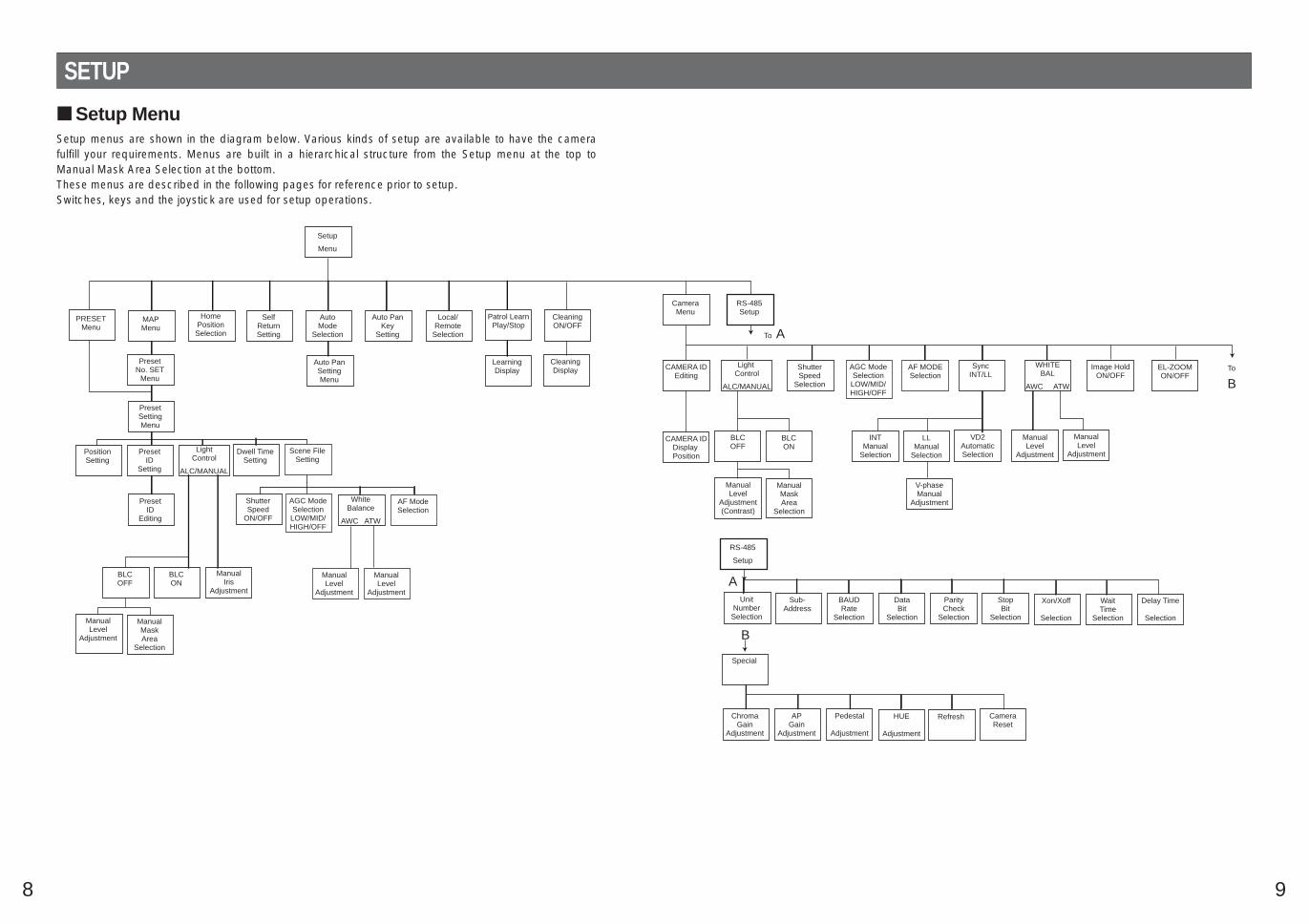
Setup MenuSetup menus are shown in the diagram below. Various kinds of setup are available to have the camerafulfill your requirements. Menus are built in a hierarchical structure from the Setup menu at the top toManual Mask Area Selection at the bottom.These menus are described in the following pages for reference prior to setup.Switches, keys and the joystick are used for setup operations.

10
Open special F2 key
The keys (switches) to use for setup are shown in the table below. The joystick on the connected con-troller may also be used for setup. The table also shows the functions versus the operations of the individ-ual controllers. For details, see the manual for the controller to be used. The switches and controls areabbreviated as SW and CTRL respectively in the table.
OPERATE LOGIN ALARM
FUNCTION
SX
IRIS
CLOSE OPEN
NEAR FAR
WIDE TELE
FOCUS
ZOOM
AUTO FOCUS
IRIS RESET
HOME
SET UP
ALM RECALL
CAM SETUP CAM FUNCTION
MULTI SCREEN DEF
WIPEREL-ZOOM
SHIFT
ALM RESET
VTR CAM
STILL
-1 CAM/DEC
ALM SUSPEND
+1 CAM/INC
PATROLSTOP
AUX 1
AUX 2
B/W UNIT
SEQ PAUSE
BOOST
SEQUENCE AUTOPRESET
POSI
FS
MON CAM
LOGOUTESC SET
CAMERA SITE CONTROL
UP
L R
DOWN
BUSY PROHIBITEDMONITORUNIT CAMERA
System Controller WV-CU 360
1 2 3
4 5 6
7 8 9
MON CAM
ESC SET
0
ACKRESET
BACKSEQ
FORWARDSEQ ALT
DEC–1CAM
INC+1CAM STOP1 2
AUX
CLOSE OPENIRIS
PRESET
FOCUSNEAR
ZOOMTELE
FARWIDE
System Controller WV-CU 550550B
LEFT RIGHT
UP
DOWN
ALARM BUSY
F3 F4F2F1
AF
[WV-CU550B]
[WV-CU161]
[WV-RM70]
Joystick
CAM (SET)Key
MON (ESC)Key
CAM (SET)Key
MON (ESC)Key
SET KeyCAM (SET) Key
OPERATE REMOTE
NORMAL PROGALARMRESET
SYSTEMALARM OFF
Camera Controller WV-RM 7070
Up Switch
Set SwitchRightSwitch
Left Switch DownSwitch
[WV-CU360]Joystick
Joystick
FOCUS SwitchZOOM Switch
FOCUS SwitchZOOM Switch
Up Switch
R
System Controller WV-CU
1 2 3
4 6
7 8 9
0
5
SHIFT
OPERATE ALARM
RESET
RESET
SUSPEND
CAMERASETUP
PATROLPAY
PROGRAMPRESET
CAMERAFUNCTION
SERUP
ESC
HOME
SET
PRESET WIDE TELE
NEAR
AUX1
B/W
AUTO
WIPER
AUX2
DEF
UP
DOWN
LFAR
FOCUS
IRISCLOSS OPEN
PROGRAM
ALARM
IRIS RESET
AUTO FOCUS
Left Switch
Right Switch
Down Switch
Function/Controller WV-CU550B WV-CU360 WV-CU161 WV-RM70
Open CAM SETUP See page 16CAM SETUPkey (for 2 sec-onds or more)
CAMERA SETUPkey (for 2 seco-nds or more)
See page 16
Close CAM SETUP F4 keyCAM SETUPkey (for 2 sec-onds or more)
CAMERA SETUPkey (for 2 seco-nds or more)
PROG SW
Move the cursorJoystick(←, ↑ , ↓ , →)
Joystick(←, ↑ , ↓ , →)
Direction SW(←, ↑ , ↓ , →)
Direction SW(←, ↑ , ↓ , →)
Select a parameterJoystick(←, →)
Joystick(←, →)
Direction SW(←, →)
Direction SW(←, →)
Adjust the levelJoystick(←, →)
Joystick(←, →)
Direction SW(←, →)
Direction SW(←, →)
Move the cameradirection
Joystick(←, ↑ , ↓ , →)
Joystick(←, ↑ , ↓ , →)
Joystick(←, ↑ , ↓ , →)
Direction SW(←, ↑ , ↓ , →)
Zoom & FocusZOOM CTRL &FOCUS CTRL
ZOOM CTRL &FOCUS CTRL
ZOOM CTRL &FOCUS CTRL
Direction SW(←, ↑ , ↓ , →)
Enter the setting CAM (SET) key CAM (SET) key CAM (SET) key SET SW
Open a submenu CAM (SET) key CAM (SET) key CAM (SET) key SET SW
Enter CAM ID &PRESET IDdisplay position
MON (ESC) key MON (ESC) key MON (ESC) keySET SW(for 2 secondsor more)
Enter MASKsetting
MON (ESC) key MON (ESC) key MON (ESC) keySET SW(for 2 secondsor more)
All Reset F3 key4+5+6 key(for 2 secondsor more)
4+5+6 key(for 2 secondsor more)
R+SET+L SW(for 2 secondsor more)
4+6 key(for 2 secondsor more)
4+6 key(for 2 secondsor more)
R+L SW(for 2 secondsor more)
Notes:• A changed parameter is entered only when you move the cursor to
another item or open a new menu.A changed parameter will not be entered if the setup menu is closedwithout taking either of the above steps.
• Setting procedures in the following pages are described on the assump-tion that the camera is used with WJ-SX550B Matrix Switcher and WV-CU550B System Controller.

11
Setup Menu Description Presetting(1) Position (POSITION SET)
Aligns the camera position and focal point by panning, tilting, zooming and focusing.See page 17 for the setting.
(2) Preset Identification (PRESET ID)Assigns the name for preset IDs (identification of up to 16 alphanumeric characters) and can beswitched on or off on the monitor screen.See page 19 for the setting.
(3) Light Control (ALC/MANUAL)Selects the ALC or MANUAL mode for adjust the lens iris.See page 20 for the setting.
(4) Dwell Time (DWELL TIME)Displays the picture of each camera position in the selected duration.You can select a preset duration from the menu.See page 21 for the setting.
(5) Scene File (SCENE FILE)Stores up to 10 files.Each file has a set of detailed parameters for the shutter speed, AGC, white balance, and AF mode.The scene files can be recalled later to reproduce the parameter settings under the same conditionsas stored in the files.See page 21 for the setting.
Home Position (HOME POSITION)A home position is the camera’s basic position.It returns to this position automatically when a specific time has elapsed after a manual operation. Thissetting functions only when AUTO MODE is OFF.See page 22 for the setting.
Self Return (SELF RETURN)Self-return is the time-out parameter for returning to the home position.The camera returns to AUTO MODE if it is set to ON when a specific time has elapsed after a manualoperation.See page 22 for the setting.
Auto Mode (AUTO MODE)The auto mode is used for setting the movement of the camera.You can select one from four automatic operation modes and one manual operation mode as follows:OFF: No automatic operation. The camera can be operated only manually.SEQ: The camera operates in the sequence of preset positions in numerical order.SORT: The camera operates in the sequence of preset positions counterclockwise from PanStarting Point.AUTO PAN: The camera automatically turns within the preset panning range.PATROL: The camera operates in the patrol learn function.See page 23 for the setting.

12
Auto Pan Key (AUTO PAN KEY)This setting assigns the SEQ, SORT, AUTO PAN or PATROL (PLAY) mode to the AUTO key on the con-troller.After setting this, the AUTO key performs as assigned.Note: The AUTO PAN LED on the controller does not light if the mode other than the AUTO PAN mode is
assigned.
Local/Remote (LOCAL/REMOTE)This setting determines whether the camera continues or stops the ongoing auto operation when the con-troller is turned off.LOCAL: The camera continues operating in the auto mode when the controller is turned off.REMOTE: The camera stops operating in the auto mode approx. 1 minute after the controller is turned
off.See page 25 for the setting.
Patrol Learn and Patrol Play (PATROL)A set of manual operations is stored (LEARN), reproduced (PLAY) or turned inactive (OFF). Patroloperation stops if SEQ, SORT or AUTO PAN is set to AUTO MODE on the SETUP menu. See page 26for details.

13
Cleaning (CLEANING)This is used for refreshing the electric-mechanical contacts built in the camera. Use this function formaintenance when the camera has been directed to a specific spot or panned over a specific rangefor a long time.
Image Hold (IMAGE HOLD)The camera picture remains a still image on the monitor screen or until the camera reaches the pre-set position. This function is useful for surveillance via a local area network.
Camera(1) Camera Identification (CAMERA ID)
You can use the camera identification to assign a name to the camera. The camera ID consists of upto 16 alphanumeric characters. You can select whether to have the camera ID displayed on the moni-tor screen or not. See page 28 for the setting.
(2) Light Control (ALC/MANUAL)You can select the mode for adjusting the lens iris. There are two modes as follows:ALC: The lens iris is automatically adjusted according to the brightness of the object.
You can select one of two modes (BLC ON or BLC OFF) of backlight compensation.Backlight compensation is available for the ALC mode. It eliminates strong background lightwhich makes the camera picture dark such as a spotlight.
MANUAL: The lens iris is fixed at the value that you have set regardless of the brightness of theobject.
• ALC Mode with BLC ONAn important object in a scene is usually placed in the center of the monitor screen. By the setup,more photometric weight is given to the center of the screen than to the edge of the screen (wherebright backlight would most likely be located). In such a case, the object at the center of the screencan be still clearly seen even though the backlight may vary.See page 30 for the setting.
• ALC Mode with BLC OFFThis mode is effective when a main object in the scene is not located in the center of the screen but asource of bright light is located near the center of the scene. In this mode, the picture is divided into48 areas that mask the light to keep the clarity of the picture.

14
Note: The result of field setup of the mask area and level adjustment is fed back (effected) to the lensiris control in ALC mode.
(3) Shutter Speed (SHUTTER)You can select a shutter speed of 1/60 (OFF), 1/100, 1/250, 1/500, 1/1 000, 1/2 000, 1/4 000, and1/10 000 seconds.See page 32 for the setting.
(4) Gain Control (AGC)You can set the gain (brightness level portion of an image) to automatic adjustment [Automatic GainControl ON (LOW, MID, HIGH)] or fixed (Automatic Gain Control OFF).See page 32 for the setting.
(5) Synchronization (SYNC)You can select the internal sync (INT) mode or the line-lock sync (LL) mode. Additionally, this modelaccepts the VD2 signal (multiplexed vertical drive signal with the composite video output signal) froma specified component. Whenever the VD2 signal is supplied to this camera, the camera automatical-ly switches to the VD2 sync mode.When you select the line-lock sync (LL) mode, you can set vertical phase adjustment.See page 33 for the setting.
Important Notices:The priority of sync modes is given as follows:1. Multiplexed vertical drive (VD2) (highest)2. Line-lock (LL)3. Internal sync (INT) (lowest)
Note: The priority of the automatic sync mode is the same as shown above.

15
(6) White Balance (WHITE BAL)You can select one of two modes for white balance adjustment as follows:
• Auto-Tracing White Balance (ATW)In this mode, the color temperature is monitored continuously and thereby white balance is set auto-matically. The color temperature range for the proper white balance is approx.2 600 - 6 000 K. Properwhite balance may not be obtained under the following conditions:1. The color temperature is out of the 2 600 - 6 000 K range.2. When the scene contains mostly high color temperature (bluish) objects, such as a blue sky.3. When the scene is dim.
In these cases, select the AWC mode.
• Automatic White Balance (AWC)In this mode, accurate white balance is obtained within a color temperature range of approx. 2 300 -10 000 K.See page 34 for the setting.
(7) Auto Focus (AF MODE)The camera adjusts the focus automatically by sensing sharpness in the center of the picture. S, Mand L stand for the breadth of the sensing area: Small, Middle and Large.See page 36 for details.MANUAL S, M, L: Auto-focus is activated when the AF key on the controller is pressed.AUTO S, M, L: Auto-focus is activated automatically while operating manually: pan, tilt or zoom.
(8) Electronic Zoom (EL-ZOOM)Up to 2-fold electronic zooming is available besides 18-fold optical zooming.
(9) Image Hold (IMAGE HOLD)The camera picture remains a still image on the monitor screen until the camera reaches the presetposition. This function is useful for surveillance via a local area network.
(10)Special Menu (SPECIAL)This menu allows you to adjust and set up the following items and functions: chroma level, aperturelevel, pedestal level, hue adjustment and refresh function.You can also reset your parameters to the values preset at the factory.See page 38 for the setting.
RS485 communicationCamera communication parametersSee the following items pages for the setting.
• Full/Half duplex (page 46)• Transmission Speed (2 400 - 19 200 bps) (page 40)• Parity bit, Stop bit, Flow control (pages 40 and 41)• Wait time, Delay time (page 41)• Camera units (96 units max.) (page 44)• Termination ON/OFF (page 46)• Reset parameters (page 43)

16
SETTING PROCEDURESThe following setting procedures are described on the assumption that this model is used in combinationwith the WJ-SX550B Matrix Switcher and WV-CU550B System Controller. In case of using a controllerother than the WV-CU550B, refer to the table on page 10.
Menu Display Setup Menu Display
WV-CU550B1. Select the camera number you want to set up and a monitor to
display the SET UP MENU.2. Display the D4 menu on the LCD by pressing the appropriate cur-
sor buttons.3. Press the F1 button.
The SET UP MENU appears on the monitor screen.4. To close the SET UP MENU, press the F4 button.
WV-CU360Press the CAM SETUP key for 2 seconds or more to open theSETUP menu.
WV-CU161Press the CAMERA SETUP key for 2 seconds or more to open theSETUP menu.
WV-RM701. Turn the MODE SELECTION switch to NORMAL or ALARM OFF.2. Press the PROG switch for 2 seconds or more to open the
Program Menu.3. Move the cursor to Camera Set Up Menu, and press the SET
switch to open the SETUP MENU.
Submenu DisplayThe items marked can be selected/changed on the submenu.
• Move the cursor to an item with the mark and press the CAM(SET) key. The submenu appears.
D4 menu
F1
F1 F2 F3 F4
Camera Set Up Menu Res A.Res Exit
F2 F3 F4
Camera Set Up Menu On Exit
** RS485 SET UP ** UNIT NUMBERSUB ADDRESS BAUD RATEDATA BITPARITY CHECKSTOP BITXON/XOFFWAIT TIMEALARM DATADELAY TIMERET
1-----192008NONE1NOT USEOFF------
Submenu(for RS485 setup)
** SET UP MENU **PRESET 1 MAP HOME POSITION SELF RETURN AUTO MODE AUTO PAN KEY LOCAL/REMOTE PATROL CLEANINGCAMERARS485 SET UP
OFFOFFOFFAUTO PANLOCALSTOPOFF
Setup menu

17
Presetting Preset Menu Display1. Displaying the preset menu directly
(1) Move the cursor to PRESET 1 and move the joystick to theright or left to select the position number to be set.
(2) Press the CAM (SET) key.The preset setting menu appears on the monitor screen.
2. Displaying the preset menu from the PRESET NUMBER SET menu(1) Move the cursor to MAP and press the CAM (SET) key.
The PRESET NUMBER SET menu appears on the monitorscreen.
(2) Move the cursor to the position number to be set and pressthe CAM (SET) key.
Notes:• The * mark means that the position number has been preset.• The character H means the home position.• On the second bottom line, the preset ID appears respective
to the selected number. “DOOR” next to “ID” is for presetposition number 1 in the example shown right.
Position Setting (POSITION SET)1. Move the cursor to POSITION SET on the preset setting menu and
press the CAM (SET) key.The position setting menu appears.
2. To Set Panning/Tilting Positions(1) Move the cursor to PUSH SET for PAN/TILT and press the
CAM (SET) key. The PAN/TILT setting menu appears.(2) Select panning/tilting positions by moving the joystick up and
down, right and left, and press the CAM (SET) key.The positions are set and the screen returns to the positionsetting menu.
** SET UP MENU **PRESET 1 MAP HOME POSITION SELF RETURN AUTO MODE AUTO PAN KEY LOCAL/REMOTE PATROL CLEANINGCAMERARS485 SET UP
OFFOFFOFFAUTO PANLOCALSTOPOFF
Setup menu
** PRESET NUMBER SET **
2 6 10 14 18 22 26 30
1 5 9 13 17 21 25 29 ID:DOORRET
3 7 11 15 19 23 27 31
4 8 12 16 20 24 28 32
PRESET NUMBER SET menu
PRESET NO. 1*
POSITION SETPRESET IDALC/MANUALDWELL TIMESCENE FILEPRESET SPEED
RET DEL
ON ALC 10SOFF ••••••••|L H
Preset setting menu
→PUSH SET→PUSH SET
** POSITION 1 **PAN/TILTZOOM/FOCUS
PAN OFFSET SET ← −0.0 →
RETFLOOR1DOOR
Position setting menu
→PUSH SET→PUSH SET
** POSITION 1 **PAN/TILTZOOM/FOCUS
U TILT D/L PAN RPAN OFFSET SET ← −0.0 →
RETFLOOR1DOOR
** SET UP MENU **PRESET 1* MAP HOME POSITION SELF RETURN AUTO MODE AUTO PAN KEY LOCAL/REMOTE PATROL CLEANINGCAMERARS485 SET UP
OFFOFFOFFAUTO PANLOCALSTOPOFF
Setup menu
PAN/TILT setting menu

18
3. Pan OffsetIf the camera is replaced with a new one, the pan offset functionis used to adjust its positions to be the same as before exceptpatrol setting.The controller can be downloaded or uploaded the preset posi-tion data.Caution: The preset data for other camera models (WV-CS650 for
example) is incompatible with WV-CS564's. WV-CS564's pre-set data will be destroyed if you upload the conventionaldata. If this happened, reset the WV-CS564 to the default set-tings. Download the factory settings into the controller andupload the correct preset data newly to the initialized WV-CS564.
(1) Display the PRESET NUMBER SET menu.(2) Select a position number for the picture to be most enlarged
among the numbers by using the joystick. Then press theCAM (SET) key. The position setting menu appears.
(3) Move the cursor to PAN OFFSET SET and select the right orleft arrow by moving the joystick.
(4) Press the CAM (SET) key until the desired offset valueappears.
(5) Move the cursor to other than PAN OFFSET SET, and pressthe MON (ESC) key.
Notes:• Further adjustment of the other positions is unnecessary. This
adjustment applies to all other positions.• Make sure to move the cursor before pressing the key in step
5. Otherwise the settings will be ignored.• Retry when the camera fails to upload or download the data.
4. To Set the Lens Zoom and Focus Positions(1) Move the cursor to PUSH SET for ZOOM/FOCUS and press
the CAM (SET) key. The ZOOM/FOCUS setting menuappears.
(2) Select a zoom position by moving the zoom control up anddown, and a focus position by moving the focus control upand down, and then press the CAM (SET) key.The positions are set and the screen returns to the positionsetting menu.Notes:
• When the camera is used at a nearly horizontal angle, thefocus may not be adjustable to a high level of accuracy.
• If you move the cursor to the position number and movethe joystick right or left, the position number can beselected.The selected preset position number can also be set afterpressing the CAM (SET) key.
• The preset and camera IDs appear at the lower-left cor-ner of the position setting menu after setting them.
5. Move the cursor to RET and press the CAM (SET) key to return tothe preset setting menu.
→PUSH SET→PUSH SET
** POSITION 1 **PAN/TILTZOOM/FOCUS
PAN OFFSET SET ← −0.0 →
RETFLOOR1DOOR
Position setting menu
** POSITION 1 **PAN/TILTZOOM/FOCUS
U ZOOM D/L FOCUS R
PAN OFFSET SET ← −0.0 →
RETFLOOR1DOOR
→PUSH SET→PUSH SET
→PUSH SET→PUSH SET
** POSITION 1 **PAN/TILTZOOM/FOCUS
PAN OFFSET SET ← −0.0 →
RETFLOOR1DOOR
Position setting menu
** PRESET NUMBER SET **
2 6 10 14 18 22 26 30
1 5 9 13 17 21 25 29 ID:DOORRET
3 7 11 15 19 23 27 31
4 8 12 16 20 24 28 32
PRESET NUMBER SET menu
→PUSH SET→PUSH SET
** POSITION 1 **PAN/TILTZOOM/FOCUS
PAN OFFSET SET ← −0.0 →
RETFLOOR1DOOR
Position setting menu
ZOOM/FOCUS setting menu
19
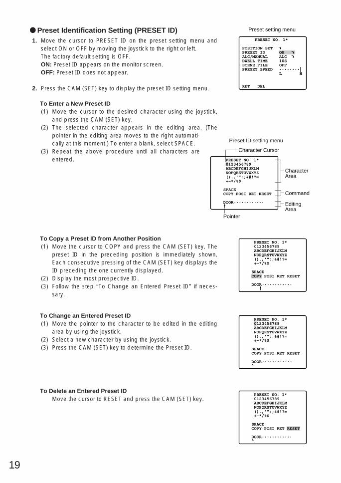
Preset Identification Setting (PRESET ID)1. Move the cursor to PRESET ID on the preset setting menu and
select ON or OFF by moving the joystick to the right or left.The factory default setting is OFF.ON: Preset ID appears on the monitor screen.OFF: Preset ID does not appear.
2. Press the CAM (SET) key to display the preset ID setting menu.
To Enter a New Preset ID(1) Move the cursor to the desired character using the joystick,
and press the CAM (SET) key.(2) The selected character appears in the editing area. (The
pointer in the editing area moves to the right automati-cally at this moment.) To enter a blank, select SPACE.
(3) Repeat the above procedure until all characters areentered.
To Copy a Preset ID from Another Position(1) Move the cursor to COPY and press the CAM (SET) key. The
preset ID in the preceding position is immediately shown.Each consecutive pressing of the CAM (SET) key displays theID preceding the one currently displayed.
(2) Display the most prospective ID.(3) Follow the step “To Change an Entered Preset ID” if neces-
sary.
To Change an Entered Preset ID(1) Move the pointer to the character to be edited in the editing
area by using the joystick.(2) Select a new character by using the joystick.(3) Press the CAM (SET) key to determine the Preset ID.
To Delete an Entered Preset IDMove the cursor to RESET and press the CAM (SET) key.
PRESET NO. 1*
POSITION SETPRESET IDALC/MANUALDWELL TIMESCENE FILEPRESET SPEED
RET DEL
ON ALC 10SOFF••••••••|L H
Preset setting menu
Command
EditingArea
CharacterArea
Pointer
Character Cursor
PRESET NO. 1* 0123456789 ABCDEFGHIJKLM NOPQRSTUVWXYZ ().,'":;&#!?= +-*/%$
SPACE COPY POSI RET RESET
DOOR............
Preset ID setting menu
PRESET NO. 1* 0123456789 ABCDEFGHIJKLM NOPQRSTUVWXYZ ().,'":;&#!?= +-*/%$
SPACE COPY POSI RET RESET
DOOR............
PRESET NO. 1* 0123456789 ABCDEFGHIJKLM NOPQRSTUVWXYZ ().,'":;&#!?= +-*/%$
SPACE COPY POSI RET RESET
DOOR............
PRESET NO. 1* 0123456789 ABCDEFGHIJKLM NOPQRSTUVWXYZ ().,'":;&#!?= +-*/%$
SPACE COPY POSI RET RESET
DOOR............

20
To Set a Display Position for a Preset ID(1) Move the cursor to POSI and press the CAM (SET) key. The
display position set menu appears.(2) Using the joystick, move the ID to the desired position on the
monitor screen, and press the MON (ESC) key. The displayposition is set and the monitor screen returns to the preset IDsetting menu.
To Enter the Next ID without Returning to the Preset SettingMenu(1) In the preset ID setting menu, move the cursor to the top line
and select the desired position number by moving the joy-stick to the right or left.
(2) Enter, copy, change or delete the ID as described above.
To Return to the Preset Setting MenuMove the cursor to RET and press the CAM (SET) key.
Light Control Setting (ALC/MANUAL)1. Move the cursor to ALC/MANUAL and select ALC or MANUAL by
moving the joystick to the right or left.The factory default setting is ALC.ALC: The lens iris is automatically adjusted to suit the brightness
of the object.MANUAL: The lens iris is fixed at the set value regardless of the
brightness of the object.
2. In case of ALC Press the CAM (SET) key. The backlight compensation menuappears on the monitor screen. See page 30 for the setting.
3. In case of MANUAL
Press the CAM (SET) key. The setting menu appears on the moni-tor screen. Set the lens iris level as desired by moving the joystickto the right or left.
PRESET NO. 1* 0123456789 ABCDEFGHIJKLM NOPQRSTUVWXYZ ().,'":;&#!?= +-*/%$
SPACE COPY POSI RET RESET
DOOR............
FLOOR 1DOOR
PRESET NO. 1* 0123456789 ABCDEFGHIJKLM NOPQRSTUVWXYZ ().,'":;&#!?= +-*/%$
SPACE COPY POSI RET RESET
DOOR............
Display position set menu
PRESET NO. 1*
POSITION SETPRESET IDALC/MANUALDWELL TIMESCENE FILEPRESET SPEED
RET DEL
ON ALC 10SOFF••••••••|L H
Preset setting menu
** MANUAL CONT **
IRIS
RET
••••|••••CLOSE OPEN
Manual setting menu

21
Dwell Time (DWELL TIME)• Move the cursor to DWELL TIME and set a dwell time by moving
the joystick to the right or left. The factory default setting is 10S.Dwell time changes as follows:
S stands for second(s), and MIN stands for minute(s).
Scene File Setting (SCENE FILE)1. To set a scene file number
Move the cursor to SCENE FILE and select a scene file number (1to 10, or OFF) by moving the joystick to the right or left. The facto-ry default setting is OFF. No scene file is selected at OFF.
2. To set scene file detailsMove the cursor to a scene file number and press the CAM (SET)key. The setting menu appears.See the pages below for the setting.
Shutter speed: page 32AGC: page 32White balance: page 34Auto focus: page 36
Preset Speed Setting (PRESET SPEED)• Move the cursor to PRESET SPEED and select a speed by moving
the joystick to the right or left.
To Return to the Preset Number Set Menu• Move the cursor to RET and press the CAM (SET) key. The PRE-
SET NUMBER SET menu appears with the * mark on the right ofthe preset position number.
To Return to the Setup Menu• Move the cursor to RET and press the CAM (SET) key.
2S 3S 5S 10S 30S 1MIN 2MIN 3MIN 4MIN
** SCENE FILE 1 **
SHUTTERAGCWHITE BALAF MODE
RET
OFFON(MID)ATW MANUAL S
Scene file setting menu
PRESET NO. 1*
POSITION SETPRESET IDALC/MANUALDWELL TIMESCENE FILEPRESET SPEED
RET DEL
ON ALC 10S1 ••••••••|L H
Preset setting menu
PRESET NO. 1*
POSITION SETPRESET IDALC/MANUALDWELL TIMESCENE FILEPRESET SPEED
RET DEL
ON ALC 10SOFF••••••••|L H
Preset setting menu
** PRESET NUMBER SET **
2 6 10 14 18 22 26 30
1* 5 9 13 17 21 25 29 ID:DOORRET
3 7 11 15 19 23 27 31
4 8 12 16 20 24 28 32
PRESET NUMBER SET menu
PRESET NO. 1*
POSITION SETPRESET IDALC/MANUALDWELL TIMESCENE FILEPRESET SPEED
RET DEL
ON ALC 10SOFF••••••••|L H
Preset setting menu
PRESET NO. 1*
POSITION SETPRESET IDALC/MANUALDWELL TIMESCENE FILEPRESET SPEED
RET DEL
ON ALC 10SOFF••••••••|L H
Preset setting menu

22
Deleting Preset Positions1. Move the cursor to PRESET 1* and select the position number to
be deleted by using the joystick.
2. Press the CAM (SET) key to display the preset setting menu.
3. Move the cursor to DEL and press the CAM (SET) key.This deletes the preset position and the PRESET NUMBER SETmenu appears. The * mark on the right of the number disappears.Note: Your selected preset number is cancelled only in the SEQ
and SORT mode. The previously set parameters (for PAN,TILT positions, etc.) are not changed. If you want to changethese parameters, you must set them again.
Home Position Setting(HOME POSITION)
1. To set a position number for the home positionMove the cursor to HOME POSITION and select the desired posi-tion number by moving the joystick to the right or left.The factory default setting is OFF.
2. Select OFF if you are not using the home position function.Note: This setting functions only when AUTO MODE is set to OFF.
Self Return Setting (SELF RETURN)1. To set a time-out parameter for return to the home position
Move the cursor to SELF RETURN and select a return time bymoving the joystick to the right or left.The factory default setting is OFF.Return time changes as follows:
2MIN 3MIN 5MIN 10MIN
60MIN 30MIN 20MIN
1MIN
OFF
MIN stands for minute(s).
Note: The camera will return to the auto mode if that is set to SEQ,SORT, AUTO PAN or PATROL when a specific time haselapsed after a manual operation.
PRESET NO. 1*
POSITION SETPRESET IDALC/MANUALDWELL TIMESCENE FILEPRESET SPEED
RET DEL
ON ALC 10SOFF••••••••|L H
Preset setting menu
** SET UP MENU **PRESET 1* MAP HOME POSITION SELF RETURN AUTO MODE AUTO PAN KEY LOCAL/REMOTE PATROL CLEANINGCAMERARS485 SET UP
OFFOFFOFFAUTO PANLOCALSTOPOFF
Setup menu
** PRESET NUMBER SET **
2 6 10 14 18 22 26 30
1 5 9 13 17 21 25 29 ID:DOORRET
3 7 11 15 19 23 27 31
4 8 12 16 20 24 28 32
PRESET NUMBER SET menu
** SET UP MENU **PRESET 1 MAP HOME POSITION SELF RETURN AUTO MODE AUTO PAN KEY LOCAL/REMOTE PATROL CLEANINGCAMERARS485 SET UP
15OFFOFFAUTO PANLOCALSTOPOFF
Setup menu
** SET UP MENU **PRESET 1 MAP HOME POSITION SELF RETURN AUTO MODE AUTO PAN KEY LOCAL/REMOTE PATROL CLEANINGCAMERARS485 SET UP
OFF10MINOFFAUTO PANLOCALSTOPOFF
Setup menu

23
Auto Mode Selection (AUTO MODE)1. To set auto mode
Move the cursor to AUTO MODE and select a mode by movingthe joystick to the right or left.The factory default setting is OFF.Modes change as follows:
OFF: No automatic operation. The camera can be operated onlymanually.
SEQ: The camera operates in the sequence of preset positions innumerical order.
SORT: The camera operates in the sequence of preset positionscounterclockwise from Pan Starting Point.
AUTO PAN: The camera automatically turns within the presetpanning range.
PATROL: The camera operates in the patrol learn function.
2. When the AUTO PAN mode is selected, set details as follows:Move the cursor to AUTO PAN and press the CAM (SET) keyto display the AUTO PAN setting menu.
3. To set a panning starting point and panning endpointFollow the steps below.(1) Move the cursor to POSITION and press the CAM (SET) key.
The cursor moves to START.(2) Move the joystick to the right or left to select a panning start-
ing point and press the CAM (SET) key.This determines the starting point and the cursor moves toEND.
(3) Move the joystick to the right or left to select a panning end-point and press the CAM (SET) key.This determines the endpoint and the cursor moves to POSI-TION.
4. To set a panning speedMove the cursor to SPEED, and move the joystick to the right orleft to set a panning speed.The panning speed increases when the joystick is moved to theright, and decreases when it is moved to the left.
Caution: If the panning range is changed after the camera has notpanned for a long time or has been panning in the same panningrange, the picture may not be clear or noise may appear. In thiscase, pan the camera fully several times.If this does not eliminate the problem, refer servicing to qualifiedservice personnel.
OFF SEQ SORT AUTO PAN PATROL
** SET UP MENU **PRESET 1 MAP HOME POSITION SELF RETURN AUTO MODE AUTO PAN KEY LOCAL/REMOTE PATROL CLEANINGCAMERARS485 SET UP
OFFOFFOFFAUTO PANLOCALSTOPOFF
Setup menu
** AUTO PAN **
POSITION
SPEED
PAN LIMITENDLESSDWELL TIME
RET
STARTEND••••|••••L HOFFOFF1S
AUTO PAN setting menu
** AUTO PAN **
POSITION
SPEED
PAN LIMITENDLESSDWELL TIME
RET
STARTEND••••|••••L HOFFOFF1S
** AUTO PAN **
POSITION
SPEED
PAN LIMITENDLESSDWELL TIME
RET
STARTEND••••|••••L HOFFOFF1S
** AUTO PAN **
POSITION
SPEED
PAN LIMITENDLESSDWELL TIME
RET
STARTEND••••|••••L HOFFOFF1S
24
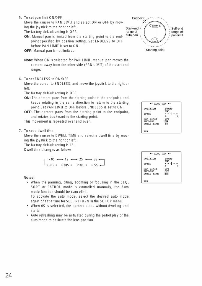
5. To set pan limit ON/OFFMove the cursor to PAN LIMIT and select ON or OFF by mov-ing the joystick to the right or left.The factory default setting is OFF.ON: Manual pan is limited from the starting point to the end-
point specified by position setting. Set ENDLESS to OFFbefore PAN LIMIT is set to ON.
OFF: Manual pan is not limited.
Note: When ON is selected for PAN LIMIT, manual pan moves thecamera away from the other side (PAN LIMIT) of the start-endrange.
6. To set ENDLESS to ON/OFFMove the cursor to ENDLESS, and move the joystick to the right orleft.The factory default setting is OFF.ON: The camera pans from the starting point to the endpoint, and
keeps rotating in the same direction to return to the startingpoint. Set PAN LIMIT to OFF before ENDLESS is set to ON.
OFF: The camera pans from the starting point to the endpoint,and rotates backward to the starting point.
This movement is repeated over and over.
7. To set a dwell timeMove the cursor to DWELL TIME and select a dwell time by mov-ing the joystick to the right or left.The factory default setting is 1S.Dwell time changes as follows:
Notes:• When the panning, tilting, zooming or focusing in the SEQ,
SORT or PATROL mode is controlled manually, the Automode function should be cancelled.To activate the auto mode, select the desired auto modeagain or set a time for SELF RETURN in the SET UP menu.
• When 0S is selected, the camera stops without dwelling andstarts.
• Auto refreshing may be activated during the patrol play or theauto mode to calibrate the lens position.
** AUTO PAN **
POSITION
SPEED
PAN LIMITENDLESSDWELL TIME
RET
STARTEND••••|••••L HOFFON1S
** AUTO PAN **
POSITION
SPEED
PAN LIMITENDLESSDWELL TIME
RET
STARTEND••••|••••L HOFFOFF1S
0S 1S 2S 3S
30S 5S10S20S
Camera
Endpoint
Starting point
Start-endrange ofauto pan
Self-end range ofpan limit

25
Auto Pan Key Setting(AUTO PAN KEY)
This is used for assigning one of the following auto functions to theAUTO key on the controller. Pressing the AUTO key activates theassigned function after this setting.
• Move the cursor to AUTO PAN KEY and select an auto function bymoving the joystick to the right or left.The factory default setting is AUTO PAN.Mode changes as follows:
AUTO PAN: assigns auto panning function to the key.SEQ: assigns the sequence function to the key.SORT: assigns the sort function to the key.PATROL: assigns the patrol play function to the key.Note: Auto pan LED on the controller does not light if a function
other than the auto pan function is assigned. The auto panfunction does not stop with the AUTO PAN key.
Local/Remote Setting(LOCAL/REMOTE)
• Move the cursor to LOCAL/REMOTE, and move the joystick to theright or left.The factory default setting is LOCAL.You can toggle between LOCAL and REMOTE.Note: The REMOTE does not work when the WV-RM70, WV-
CU360, WV-CU161, WJ-FS616 or WV-CU550 series is con-nected. Make sure that LOCAL is selected in this case.
AUTO PAN SEQ SORT
PATROL
** SET UP MENU **PRESET 1 MAP HOME POSITION SELF RETURN AUTO MODE AUTO PAN KEY LOCAL/REMOTE PATROL CLEANINGCAMERARS485 SET UP
OFFOFFOFFAUTO PANLOCALSTOPOFF
Setup menu
** SET UP MENU **PRESET 1 MAP HOME POSITION SELF RETURN AUTO MODE AUTO PAN KEY LOCAL/REMOTE PATROL CLEANINGCAMERARS485 SET UP
OFFOFFOFFAUTO PANLOCALSTOPOFF
Setup menu
** SET UP MENU **PRESET 1 MAP HOME POSITION SELF RETURN AUTO MODE AUTO PAN KEY LOCAL/REMOTE PATROL CLEANINGCAMERARS485 SET UP
OFFOFFOFFAUTO PANLOCALSTOPOFF
Special 1 menu
26
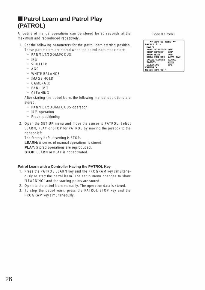
Patrol Learn and Patrol Play(PATROL)A routine of manual operations can be stored for 30 seconds at themaximum and reproduced repetitively.
1. Set the following parameters for the patrol learn starting position.These parameters are stored when the patrol learn mode starts.
• PAN/TILT/ZOOM/FOCUS• IRIS• SHUTTER• AGC• WHITE BALANCE• IMAGE HOLD• CAMERA ID• PAN LIMIT• CLEANING
After starting the patrol learn, the following manual operations arestored.
• PAN/TILT/ZOOM/FOCUS operation• IRIS operation• Preset positioning
2. Open the SET UP menu and move the cursor to PATROL. SelectLEARN, PLAY or STOP for PATROL by moving the joystick to theright or left.The factory default setting is STOP.LEARN: A series of manual operations is stored.PLAY: Stored operations are reproduced.STOP: LEARN or PLAY is not activated.
Patrol Learn with a Controller Having the PATROL Key1. Press the PATROL LEARN key and the PROGRAM key simultane-
ously to start the patrol learn. The setup menu changes to show“LEARNING” and the starting points are stored.
2. Operate the patrol learn manually. The operation data is stored.3. To stop the patrol learn, press the PATROL STOP key and the
PROGRAM key simultaneously.
27
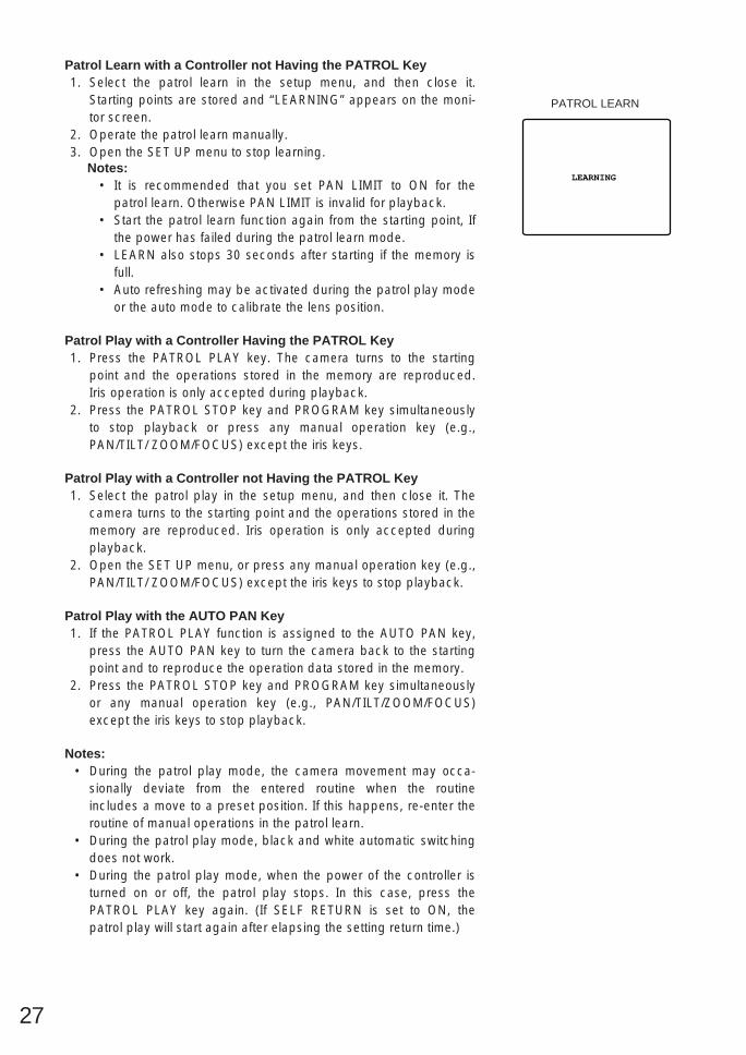
Patrol Learn with a Controller not Having the PATROL Key1. Select the patrol learn in the setup menu, and then close it.
Starting points are stored and “LEARNING” appears on the moni-tor screen.
2. Operate the patrol learn manually.3. Open the SET UP menu to stop learning.
Notes:• It is recommended that you set PAN LIMIT to ON for the
patrol learn. Otherwise PAN LIMIT is invalid for playback.• Start the patrol learn function again from the starting point, If
the power has failed during the patrol learn mode.• LEARN also stops 30 seconds after starting if the memory is
full.• Auto refreshing may be activated during the patrol play mode
or the auto mode to calibrate the lens position.
Patrol Play with a Controller Having the PATROL Key1. Press the PATROL PLAY key. The camera turns to the starting
point and the operations stored in the memory are reproduced.Iris operation is only accepted during playback.
2. Press the PATROL STOP key and PROGRAM key simultaneouslyto stop playback or press any manual operation key (e.g.,PAN/TILT/ ZOOM/FOCUS) except the iris keys.
Patrol Play with a Controller not Having the PATROL Key1. Select the patrol play in the setup menu, and then close it. The
camera turns to the starting point and the operations stored in thememory are reproduced. Iris operation is only accepted duringplayback.
2. Open the SET UP menu, or press any manual operation key (e.g.,PAN/TILT/ ZOOM/FOCUS) except the iris keys to stop playback.
Patrol Play with the AUTO PAN Key1. If the PATROL PLAY function is assigned to the AUTO PAN key,
press the AUTO PAN key to turn the camera back to the startingpoint and to reproduce the operation data stored in the memory.
2. Press the PATROL STOP key and PROGRAM key simultaneouslyor any manual operation key (e.g., PAN/TILT/ZOOM/FOCUS)except the iris keys to stop playback.
Notes: • During the patrol play mode, the camera movement may occa-
sionally deviate from the entered routine when the routineincludes a move to a preset position. If this happens, re-enter theroutine of manual operations in the patrol learn.
• During the patrol play mode, black and white automatic switchingdoes not work.
• During the patrol play mode, when the power of the controller isturned on or off, the patrol play stops. In this case, press thePATROL PLAY key again. (If SELF RETURN is set to ON, thepatrol play will start again after elapsing the setting return time.)
LEARNING
PATROL LEARN

28
Cleaning (CLEANING)Built-in electric mechanical contacts are refreshed at regularintervals (approx. 7 days) if CLEANING is set to ON.A dry contract affects adversely picture quality and motors oper-ation.
1. Move the cursor to CLEANING and select ON or OFF by movingthe joystick to the right or left.The factory default setting is OFF.
ON: The contacts are cleaned as programmed for about 1minute. “CLEANING” disappears when it is over.
OFF: No contact cleaning.Note: Select OFF when the camera downloads or uploads the
preset data.
Camera SettingTo Display the Camera Setting Menu
• Move the cursor to CAMERA , and press the CAM (SET) key.The camera setting menu appears.
Camera Identification (CAMERA ID)1. Move the cursor to CAMERA ID, and select ON (to display the
camera identification) or OFF by using the joystick.The factory default setting is OFF.
2. Follow the steps below to edit the camera ID characters:2-1 Move the cursor to CAMERA ID and press the CAM (SET)
key to display the character editing menu.2-2 Move the cursor to the character you want to edit or change
by using the joystick, and press the CAM (SET) key. Theselected character appears in the editing area.
2-3 Repeat the steps above until all characters are edited.
** SET UP MENU **PRESET 1 MAP HOME POSITION SELF RETURN AUTO MODE AUTO PAN KEY LOCAL/REMOTE PATROL CLEANINGCAMERARS485 SET UP
OFFOFFOFFAUTO PANLOCALSTOPOFF
Special 1 menu
CLEANING
CLEANING
** SET UP MENU **PRESET 1 MAP HOME POSITION SELF RETURN AUTO MODE AUTO PAN KEY LOCAL/REMOTE PATROL CLEANINGCAMERARS485 SET UP
OFFOFFOFFAUTO PANLOCALSTOPOFF
Setup menu
** SET UP **CAMERA IDALC/MANUALSHUTTERAGCSYNCWHITE BALAF MODEEL-ZOOMIMAGE HOLD
RET SPECIAL
OFF ALC OFF ON(MID) INT ATW MANUAL S ON OFF

29
3. After editing the camera identification characters, follow the stepsbelow to set the position of the CAMERA ID on the monitor screen.3-1 Move the cursor to POSI, and press the CAM (SET) key to display
the ID position menu.3-2 Use the joystick to decide the position of the CAMERA ID on the
monitor screen. Press the MON (ESC) key to fix the position, andreturn to the character editing menu.
Notes:• When you want the pointer to move to a specific character in the
editing area, select a new character, and press the CAM (SET)key. This function allows you to edit or correct a specific charac-ter.
• When you want a blank space in the CAMERA ID, move the char-acter cursor to SPACE, and press the CAM (SET) key.
• When you want to erase all characters in the editing area, movethe cursor to RESET and press the CAM (SET) key.
• The positioning of the CAMERA ID stops at the edges of thescreen.
• The CAMERA ID moves faster when the joystick is kept at theright or left for one second or more.
• To return to SET UP for setting other items, move the cursor toRET, and press the CAM (SET) key.
** SET UP **CAMERA IDALC/MANUALSHUTTERAGCSYNCWHITE BALAF MODEEL-ZOOMIMAGE HOLD
RET SPECIAL
ON ALC OFF ON(MID) INT ATW MANUAL S ON OFF
CAM1

30
Light Control Setting (ALC/MANUAL)1. Display SET UP on the monitor screen.
If necessary, refer to Setup Menu Display on page 16 for detailson displaying the SET UP on the monitor screen.
2. Move the cursor to ALC/MANUAL and select ALC or MANUAL byusing the joystick.The factory default setting is ALC.When you select ALC, set backlight compensation.Note: The backlight compensation submenu associated with this
menu is described separately and should be set up afterinstalling the camera at the site and observing the actual sitepicture.
3. When MANUAL is selected, quit the setup menu by pressingMON (ESC) key. Press OPEN or CLOSE key on the controller foriris adjustments by manual.
(1) ALC Mode with BLC ON1. Press the CAM (SET) key after selecting ALC. The ALC CONT
menu appears.2. Move the cursor to the BLC and select ON.3. If you want to adjust the video output level, move the “I” cursor for
LEVEL. Adjust to the desired level by using the joystick.4. Move the cursor to RET and press the CAM (SET) key to return to
the CAM SET UP menu. (To return to the camera picture, pressthe F4 button.)
** SET UP **CAMERA IDALC/MANUALSHUTTERAGCSYNCWHITE BALAF MODEEL-ZOOMIMAGE HOLD
RET SPECIAL
ON ALC OFF ON(MID) INT ATW MANUAL S ON OFF
Camera setting menu
** ALC CONT ** BACK LIGHT COMP
BLC
LEVEL
RET
ON
••••|••••- +
** ALC CONT ** BACK LIGHT COMP
BLC
MASK SET
LEVEL
RET
OFF
••••|••••- +
Backlight compensation menu

31
(2) ALC Mode with BLC OFF1. Move the cursor to the BLC and select OFF. (When you select
MANUAL, BLC is not available.) The MASK SET appears on themenu.
2. Move the cursor to MASK SET and press the CAM (SET) key. The48 mask areas appear on the monitor screen. The cursor is blink-ing in the top left corner of the screen.
3. To mask an area where backlight is bright, move the cursor to thatarea and press the CAM (SET) key. The mask turns to white.Repeat this procedure to mask the desired area.
4. To cancel a masked area, move the cursor to that area, and pressthe CAM (SET) key. To cancel all masking area, press the F2 but-ton of the WV-CU550B. (For the WV-RM70, press the right and leftswitches simultaneously.)
5. After masking is completed, press the MON (ESC) key. The 48mask areas on the monitor screen disappear and the ALC CONTmenu appears.
6. If you want to change the video output level (picture contrast),move the “I” cursor for LEVEL and adjust the level.
7. Move the cursor to RET and press the CAM (SET) key to return tothe CAM SET UP menu. (To return to the camera picture, pressthe F4 button.)
Blinking
Blinking
Blinking
Turns to white
** ALC CONT ** BACK LIGHT COMP
BLC
MASK SET
LEVEL
RET
OFF
••••|••••- +
** ALC CONT ** BACK LIGHT COMP
BLC
MASK SET
LEVEL
RET
OFF
••••|••••- +

32
Shutter Speed Setting (SHUTTER)1. Display SET UP on the monitor screen.
If necessary, refer to Setup Menu Display on page 16 for detailson displaying the SET UP menu on the monitor screen.
2. Move the cursor to SHUTTER and select the electronic shutterspeed by using the joystick. The factory default setting is OFF.The electronic shutter speed changes as follows by operating thejoystick:
• When OFF is selected for BLC on the ALC CONT menu
Gain Control (AGC)1. Display SET UP on the monitor screen.
If necessary, refer to Setup Menu Display on page 16 for detailson displaying the SET UP menu on the monitor screen.
2. Move the cursor to AGC and select automatic level adjustmentON (LOW), ON (MID), ON (HIGH) or fixed level (OFF) by using thejoystick.The factory default setting is ON (MID).ON (LOW): Selects lower gain control.ON (MID): Selects normal gain control.ON (HIGH): Selects higher gain control.OFF (Fixed Level): Disables the gain control function.
Note:• Even if AGC is set to ON and if the noise reduction function is
enabled, afterimages may be produced by shooting a movingobject or by panning or tilting the camera.
** SET UP **CAMERA IDALC/MANUALSHUTTERAGCSYNCWHITE BALAF MODEEL-ZOOMIMAGE HOLD
RET SPECIAL
ON ALC OFF ON(MID) INT ATW MANUAL S ON OFF
Camera setting menu
** SET UP **CAMERA IDALC/MANUALSHUTTERAGCSYNCWHITE BALAF MODEEL-ZOOMIMAGE HOLD
RET SPECIAL
ON ALC OFF ON(MID) INT ATW MANUAL S ON OFF
Camera setting menu
OFF (1/60) 1/100
1/10 000 1/4 000 1/2 000 1/1 000
1/250 1/500

33
Synchronization (SYNC)1. Display SET UP on the monitor screen.
If necessary, refer to Setup Menu Display on page 16 for detailson displaying the SET UP menu on the monitor screen.
2. Move the cursor to SYNC and select line-lock (LL) or internal (INT)by using the joystick.The factory default setting is INT.
Important Notices:1. The priority of SYNC modes is as follows:
1. Multiplexed vertical drive (VD2) (highest priority)2. Line-lock (LL)3. Internal sync (INT) (lowest priority)
2. To use internal sync, select INT.3. Whenever the vertical drive pulse (VD2) is supplied to the cam-
era, the camera sync mode is automatically switched to the multi-plexed vertical drive (VD2) regardless which sync mode is select-ed.
Line-lock Sync Mode (LL)1. Display SET UP on the monitor screen.
(Refer to Setup Menu Display on page 16 for details on displayingthe SET UP menu on the monitor screen.)
2. Move the cursor to SYNC and select LL by using the joystick. LLsync mode is not available when the multiplexed vertical drive(VD2) pulse is supplied.
3. After selecting LL, press the CAM (SET) key.The SYNC menu appears on the monitor screen.
4. Supply the video output signal of the camera to be adjusted andthe reference camera video output signal to a dual-trace oscillo-scope.
5. Set the dual-trace oscilloscope to the vertical rate and expand thevertical sync portion on the oscilloscope.
6. Move the cursor to COARSE by using the joystick.
** SET UP **CAMERA IDALC/MANUALSHUTTERAGCSYNCWHITE BALAF MODEEL-ZOOMIMAGE HOLD
RET SPECIAL
ON ALC OFF ON(MID) INT ATW MANUAL S ON OFF
Camera setting menu
** SET UP **CAMERA IDALC/MANUALSHUTTERAGCSYNCWHITE BALAF MODEEL-ZOOMIMAGE HOLD
RET SPECIAL
ON ALC OFF ON(MID) LL ATW MANUAL S ON OFF
Camera setting menu
** SYNC **
V PHASE
COARSE
FINE
RET
1(1--16)
•|•••••••- +
SYNC menu

34
7. Use the joystick to match the vertical phases for both video outputsignals as closely as possible. (COARSE adjustment can beincremented in steps of 22.5 degrees (16 steps) with the joystick.)Note: After the 16 steps, the adjustment returns to the first step.
8. Move the cursor to FINE by using the joystick.
9. Use the joystick to match the vertical phase for both video outputsignals as closely as possible.
Notes:• When the “|” cursor reaches the “+” end, it jumps back to “–”.
At the same time, COARSE is incremented by one step toenable a continuous adjustment. The reverse takes placewhen the “|” cursor reaches the “–” end.
• When the joystick is kept at the right or left for one second ormore, the “|” cursor moves quickly.
• To reset COARSE and FINE to the preset values at the facto-ry, press the F2 button of the WV-CU550B. (For the WV-RM70, press the Right and Left switches simultaneously.)COARSE is preset at the factory to zero-crossing of the ACline phase.
• If the AC line contains noise (spike noise, etc.), the stability ofthe vertical phase of the camera video output signal may bedisturbed.
White Balance (WHITE BAL)(1) Auto-Tracing White Balance Mode (ATW)1. Display SET UP on the monitor screen.
(Refer to Setup Menu Display on page 16 for details on displayingthe SET UP menu on the monitor screen.)
2. Move the cursor to WHITE BAL and select ATW by using the joy-stick. The factory default setting is ATW.The white balance of the camera is automatically set.
3. For fine adjustment of the ATW, press the CAM (SET) key to dis-play the ATW fine adjustment menu on the monitor screen.
4. Move the cursor to R.Use the joystick to obtain the optimum amount of red gain. The “I”cursor moves to the right or left.
5. Move the cursor to B.Use the joystick to obtain the optimum amount of blue gain. The“I” cursor moves to the right or left.
6. Move the cursor to RET by using the joystick and press the CAM(SET) key to return to SET UP.
1(1--16)
- +
** SYNC **
V PHASE
COARSE
FINE
RET
** SYNC **
V PHASE
COARSE
FINE
RET
4(1--16)
••••••|••- +
** SYNC **
V PHASE
COARSE
FINE
RET
1(1--16)
•|•••••••- +
** SET UP **CAMERA IDALC/MANUALSHUTTERAGCSYNCWHITE BALAF MODEEL-ZOOMIMAGE HOLD
RET SPECIAL
ON ALC OFF ON(MID) INT ATW MANUAL S ON OFF
Camera setting menu
** ATW **
R
B
RET
••••|••••- +••••|••••- +
ATW fine adjustment menu
1 (1 - - - 16): 0 degrees2 (1 - - - 16): 22.5 degrees
16 (1 - - - 16): 337.5 degrees

35
(2) Automatic White Balance Control Mode (AWC)1. Display SET UP on the monitor screen.
(Refer to Setup Menu Display on page 16 for details on displayingthe SET UP menu on the monitor screen.)
2. Move the cursor to WHITE BAL and select AWC → PUSH SW byusing the joystick.
3. Press the CAM (SET) key to start the white balance setup. PUSHSW is highlighted to indicate that white balance is being set.
4. PUSH SW returns to normal when balance setting is completed.
5. For fine adjustment of the AWC, move the cursor to select AWCand press the CAM (SET) key to display the AWC fine adjustmentmenu on the monitor screen.
6. Move the cursor to R.Use the joystick to obtain the optimum amount of red gain. The “I”cursor moves to the right or left.
7. Move the cursor to B.Use the joystick to obtain the optimum amount of blue gain. The“I” cursor moves to the right or left.
8. Move the cursor to RET by using the joystick andpress the CAM (SET) key to return to SET UP.
** AWC **
R
B
RET
••••|••••- +••••|••••- +
AWC fine adjustment menu
** SET UP **CAMERA IDALC/MANUALSHUTTERAGCSYNCWHITE BALAF MODEEL-ZOOMIMAGE HOLD
RET SPECIAL
ON ALC OFF ON(MID) INT AWC MANUAL S ON OFF
Camera setting menu
Blue sky
Cloudy
Fine
AWC
10000 K
Bluish
Reddish
9000 K
8000 K
7000 K
6000 K
5000 K
4000 K
3000 K
2000 K
1000 K
ATW
Halogen lamp
Rainy
Partly cloudy
Fluorescentlamp
Tungstenlamp
Candle

36
Auto Focus Setting (AF MODE)1. Move the cursor to AF MODE, and select the following mode by
moving the joystick to the right or left.The factory default setting is MANUAL S.S, M and L stand for Small, Middle and Large areas in the centerof a scene that are used for sensing sharpness in auto-focusing.
MANUAL S, M, L: Brings the camera into focus when the AF keyon the controller is pressed.
AUTO S, M, L: Brings the camera into focus while operating pan,tilt or zoom manually. These may be selected in the same wayas selecting MANUAL by pressing the AF key on the con-troller.
2. To confirm auto-focus operation, press CAM (SET) key while thecursor is at AF MODE.
Notes:• The auto focus lens does not function properly in AUTO after
using WIDE lens.• The auto focus lens may not function properly in AUTO under the
following conditions.1. Dirt or water on window glass.
The auto focus may focus on the dirt or water.2. Low lighting/illumination or zone marker is blinking.3. Bright objects or high intensity objects.4. Single color with unfigured object such as white wall or fine
felt.5. No center objects, sloping objects.6. Far and near objects on the screen.
** SET UP **CAMERA IDALC/MANUALSHUTTERAGCSYNCWHITE BALAF MODEEL-ZOOMIMAGE HOLD
RET SPECIAL
ON ALC OFF ON(MID) INT ATW MANUAL S ON OFF
Camera setting menu
AUTO S AUTO M AUTO L
MANUAL L MANUAL M MANUAL S

37
Electronic Zoom (EL-ZOOM)The electronic zoom magnifies a scene 2-fold. With a 18-fold opticalzoom lens, the camera is capable of 36-fold zoom.
1. Move the cursor to EL-ZOOM and select ON or OFF by movingthe joystick to the right or left, and then press the CAM (SET) key.The factory default setting is ON.
ON: Two (2) - fold electronic zoom is available with the ZOOMswitch on the controller.
OFF: The electronic zoom function is not used.Notes:
• A scene magnified by the electronic zoom function may beinferior to a non-magnified one in picture quality.
• The electronic zoom does not function in preset position set-ting mode.
• To set preset position directly from the WV-CU360 SystemController, it is temporarily required setting the electroniczoom function to OFF.
Image Hold (IMAGE HOLD)The camera picture remains as a still image on the monitor screenuntil the camera reaches the preset position. This function is useful forsurveillance via local area network.
1. Move the cursor to IMAGE HOLD and select ON or OFF.The factory default setting is OFF.ON: The last displayed still image is shown till the camera finishes
moving to a preset position. However, the still image may bedistorted with the effect of panning or tilting.
OFF: The current image is being displayed while the camera ismoving to a preset position.
** SET UP **CAMERA IDALC/MANUALSHUTTERAGCSYNCWHITE BALAF MODEEL-ZOOMIMAGE HOLD
RET SPECIAL
ON ALC OFF ON(MID) INT ATW MANUAL S ON OFF
Camera setting menu
** SET UP **CAMERA IDALC/MANUALSHUTTERAGCSYNCWHITE BALAF MODEEL-ZOOMIMAGE HOLD
RET SPECIAL
ON ALC OFF ON(MID) INT ATW MANUAL S ON OFF
Camera setting menu
38
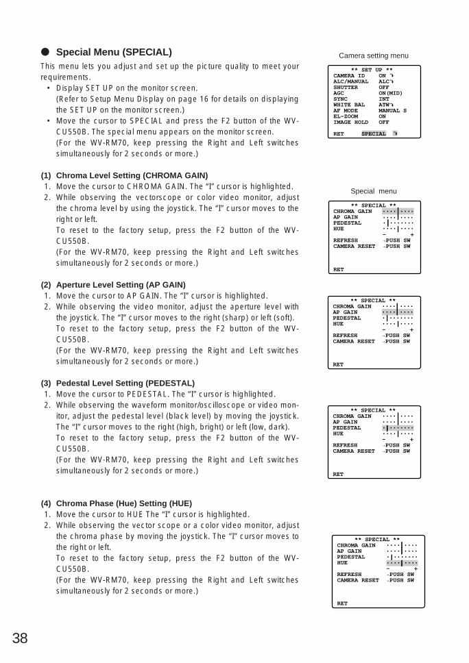
Special Menu (SPECIAL)This menu lets you adjust and set up the picture quality to meet yourrequirements.
• Display SET UP on the monitor screen.(Refer to Setup Menu Display on page 16 for details on displayingthe SET UP on the monitor screen.)
• Move the cursor to SPECIAL and press the F2 button of the WV-CU550B. The special menu appears on the monitor screen.(For the WV-RM70, keep pressing the Right and Left switchessimultaneously for 2 seconds or more.)
(1) Chroma Level Setting (CHROMA GAIN)1. Move the cursor to CHROMA GAIN. The “I” cursor is highlighted.2. While observing the vectorscope or color video monitor, adjust
the chroma level by using the joystick. The “I” cursor moves to theright or left.To reset to the factory setup, press the F2 button of the WV-CU550B.(For the WV-RM70, keep pressing the Right and Left switchessimultaneously for 2 seconds or more.)
(2) Aperture Level Setting (AP GAIN)1. Move the cursor to AP GAIN. The “I” cursor is highlighted.2. While observing the video monitor, adjust the aperture level with
the joystick. The “I” cursor moves to the right (sharp) or left (soft).To reset to the factory setup, press the F2 button of the WV-CU550B.(For the WV-RM70, keep pressing the Right and Left switchessimultaneously for 2 seconds or more.)
(3) Pedestal Level Setting (PEDESTAL)1. Move the cursor to PEDESTAL. The “I” cursor is highlighted.2. While observing the waveform monitor/oscilloscope or video mon-
itor, adjust the pedestal level (black level) by moving the joystick.The “I” cursor moves to the right (high, bright) or left (low, dark).To reset to the factory setup, press the F2 button of the WV-CU550B.(For the WV-RM70, keep pressing the Right and Left switchessimultaneously for 2 seconds or more.)
(4) Chroma Phase (Hue) Setting (HUE)1. Move the cursor to HUE The “I” cursor is highlighted.2. While observing the vector scope or a color video monitor, adjust
the chroma phase by moving the joystick. The “I” cursor moves tothe right or left.To reset to the factory setup, press the F2 button of the WV-CU550B.(For the WV-RM70, keep pressing the Right and Left switchessimultaneously for 2 seconds or more.)
** SET UP **CAMERA IDALC/MANUALSHUTTERAGCSYNCWHITE BALAF MODEEL-ZOOMIMAGE HOLD
RET SPECIAL
ON ALC OFF ON(MID) INT ATW MANUAL S ON OFF
Camera setting menu
** SPECIAL **CHROMA GAINAP GAINPEDESTALHUE
REFRESHCAMERA RESET
RET
••••|••••••••|•••••|•••••••••••|••••- +→PUSH SW→PUSH SW
Special menu
** SPECIAL **CHROMA GAINAP GAINPEDESTALHUE
REFRESHCAMERA RESET
RET
••••|••••••••|•••••|•••••••••••|••••- +→PUSH SW→PUSH SW
** SPECIAL **CHROMA GAINAP GAINPEDESTALHUE
REFRESHCAMERA RESET
RET
••••|••••••••|•••••|•••••••••••|••••- +→PUSH SW→PUSH SW
** SPECIAL **CHROMA GAINAP GAINPEDESTALHUE
REFRESHCAMERA RESET
RET
••••|••••••••|•••••|•••••••••••|••••- +→PUSH SW→PUSH SW

39
(5) To Restore the Camera Default Position (REFRESH)Move the cursor to REFRESH by using the joystick and press theF2 button of the WV-CU550B.(For the WV-RM70, WV-CU360 or WV-CU161, keep pressing theRight and Left switches simultaneously for 2 seconds or more.)
(6) Camera Resetting (CAMERA RESET)Move the cursor to CAMERA RESET by using the joystick andpress the F3 button of the WV-CU550B.The camera is reset to the factory preset parameters.(For the WV-RM70, keep pressing the Right, Left and Set switchessimultaneously for 2 seconds or more. For the WV-CU360 or WV-CU161, keep pressing the Right and Left switches and the numer-ic button 5 simultaneously for 2 seconds or more.)
(7) To Close the SPECIAL MenuMove the cursor to RET and press the CAM (SET) key.The setup menu appears on the monitor screen.
** SPECIAL **CHROMA GAINAP GAINPEDESTALHUE
REFRESHCAMERA RESET
RET
••••|••••••••|•••••|•••••••••••|••••- +→PUSH SW→PUSH SW
** SPECIAL **CHROMA GAINAP GAINPEDESTALHUE
REFRESHCAMERA RESET
RET
••••|••••••••|•••••|•••••••••••|••••- +→PUSH SW→PUSH SW
** SPECIAL **CHROMA GAINAP GAINPEDESTALHUE
REFRESHCAMERA RESET
RET
••••|••••••••|•••••|•••••••••••|••••- +→PUSH SW→PUSH SW

40
How to Reset to the Factory Preset ParametersAny of the above settings plus the ALC/MANUAL level control and phase adjustments can be reset to thefactory preset parameters by placing the cursor over the desired mode and then press the F2 button ofthe WV-CU550B. (For the WV-RM70, keep pressing the Right and Left switches simultaneously for 2 sec-onds or more.)
RS485 Setup Initial Camera Communication ParametersIn an RS485 chain the matrix switcher, PC, controllers and cameras should be set to the same protocoland parameters for communication. Confirm the system protocol and parameters prior to setting the com-munication parameters for the camera.The initial communication parameters are shown on the RS485 setup menu below. Other than the on-screen-setup parameters, the 4-bit DIP switch may be used to select 2-line (Half Duplex) or 4-line (FullDuplex) communication.
Changing the Camera Communication ParametersYou can remote control this camera by using a specified extensionunit such as a computer with a modem.1. Display the SET UP MENU. Move the cursor to RS485 SET UP
and press the CAM (SET) key. RS485 SET UP menu appears on themonitor.
2. Move the cursor to the item and select the parameter by moving thejoystick to the right or left.
Unit Number (UNIT NUMBER)Displays the unit number set by the DIP switch. If the switch is set to 1-96, select a number by moving thejoystick to the right or left. In an RS485 chain each unit must have a unique number.Default: 1. See INSTALLATION for DIP switch setting.
Sub Address (SUB ADDRESS)Do not set.
Baud Rate (BAUD RATE)Specifies the transmission speed (2 400, 4 800, 9 600, 19 200 bit per second) for the RS485 communica-tion. The factory setting is 19 200.
Data Bit (DATA BIT)Specifies the number of data bits (7 or 8 bits) for the RS485 communication. The factory setting is 8.
Parity Check (PARITY CHECK)Specifies the parity check mode (NONE, ODD, EVEN). The factory setting is NONE.
Stop Bit (STOP BIT)Specifies the number of stop bits (1 or 2 bits). The factory setting is 1.
** RS485 SET UP ** UNIT NUMBERSUB ADDRESS BAUD RATEDATA BITPARITY CHECKSTOP BITXON/XOFFWAIT TIMEALARM DATADELAY TIMERET
1-----192008NONE1NOT USEOFF------
RS485 Setup menu

41
X ON/X OFF (X ON/X OFF)Specifies whether to apply flow control or not (NOT USE, USE). The factory setting is NOT USE.
Wait Time (WAIT TIME)Specifies the time to wait until retrying after confirming that no data is received from the controller.(OFF: no retry, 100, 200, 400, 1 000 ms).The factory setting is OFF.
Delay Time (DELAY TIME)Specifies the time to transmit the acknowledge request when communicating on a 2-line connection.[----,100 ms] Default: ---- (no set).This menu appears only when a 2-line communication is used. Make sure to be 100 ms when connectingthe camera with the WJ-FS616 Video Multiplexer or Matrix Switcher WJ-SX350 in a 2-line communicationsystem.
The settings become effective with the closing of the SET UP MENU.Note: Set the same parameters for the cameras, controllers and personal computers in an RS485 chain.

43
• The following steps of installation and connection should be taken by qualified service personnel orsystem installers and should conform to all local codes.
• Make sure to switch the camera off before installation and connection.• Do not install the camera near the air outlet of an air conditioner.
Camera mounting base
Camera
Camera mounting base
Fixing screw
Loosen and push
1 2 3 4
ON
1 2 3 4
ON
5 6 7 8
SW 1 SW 2
INSTALLATION
1. Disassembling the Camera(1) Loosen the fixing screw to separate the
camera mounting base and the camera.Push up the screwdriver once beforeremoving the screw.
(2) Turn the camera mounting base approx-imately 15 degrees counterclockwiseand remove the base from the camera.
2. Setting the SwitchesThere are two DIP switches on the camera:an 8-bit switch and a 4-bit switch. The 8-bitDIP switch is used in both ways to return tothe factory default settings and to specify theunit number. The 4-bit DIP switch selects ter-mination ON/OFF and half/full duplex selec-tion for RS485 communications. Switch set-tings are read in to the camera when thepower is turned on. Make sure to turn it off,then turn it back on after changing theswitch settings. Switch positions and func-tions are shown below.
RS485 Parameter SetupThe selected protocol, communication para-meters, and set unit numbers are read intothe camera when power is switched on.1. Switch off the camera.2. Set the switch according to the function
shown in the table.3. Switch on the camera to read in the
changed switch settings.4. Switch off the camera.5. Set the unit number with the DIP switch
(see next page).6. Switch on the camera to read in the
changed switch settings.Note: The changed communication
parameters are displayed on theRS485 SETUP menu after the cam-era has been switched on.
Precautions
15°Turn 15°
Then
Camera mounting base
Remove from the camera
1 2 3 4
ON
5 6 7 8
Switch positionReturns to the factory default settings.
1 2 3 4
ON
5 6 7 8
1 2 3 4
ON
5 6 7 8
1 2 3 4
ON
5 6 7 8
Switch position Baud rate
1
1
1
None
None
None
8
8
8
19 200
9 600
4 800
Data bit Parity check
Stop bit
Parameter selection
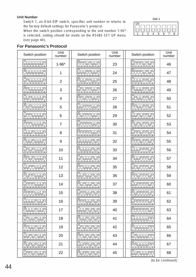
44
Unit NumberSwitch 1, an 8-bit DIP switch, specifies unit number or returns tothe factory default settings for Panasonic’s protocol.When the switch position corresponding to the unit number 1-96*is selected, setting should be made on the RS485 SET UP menu(see page 40).
1 2 3 4
ON
5 6 7 8
SW 1
For Panasonic’s Protocol
1 2 3 4
ON
5 6 7 8
Switch positionUnit
number
1 2 3 4
ON
5 6 7 8
1 2 3 4
ON
5 6 7 8
1 2 3 4
ON
5 6 7 8
1 2 3 4
ON
5 6 7 8
1 2 3 4
ON
5 6 7 8
1 2 3 4
ON
5 6 7 8
1 2 3 4
ON
5 6 7 8
1 2 3 4
ON
5 6 7 8
1 2 3 4
ON
5 6 7 8
1 2 3 4
ON
5 6 7 8
1 2 3 4
ON
5 6 7 8
1 2 3 4
ON
5 6 7 8
1 2 3 4
ON
5 6 7 8
1 2 3 4
ON
5 6 7 8
1 2 3 4
ON
5 6 7 8
1 2 3 4
ON
5 6 7 8
1 2 3 4
ON
5 6 7 8
1 2 3 4
ON
5 6 7 8
1 2 3 4
ON
5 6 7 8
1 2 3 4
ON
5 6 7 8
1 2 3 4
ON
5 6 7 8
1 2 3 4
ON
5 6 7 8
1 2 3 4
ON
5 6 7 8
1 2 3 4
ON
5 6 7 8
1 2 3 4
ON
5 6 7 8
1 2 3 4
ON
5 6 7 8
1 2 3 4
ON
5 6 7 8
1 2 3 4
ON
5 6 7 8
1 2 3 4
ON
5 6 7 8
1 2 3 4
ON
5 6 7 8
1 2 3 4
ON
5 6 7 8
Switch positionUnit
number Switch positionUnit
number
1-96*
1
2
3
4
5
6
7
8
9
10
11
12
13
14
15
16
17
18
19
20
21
22
23
24
25
26
27
28
29
30
31
32
33
34
35
36
37
38
39
40
41
42
43
44
45
46
47
48
49
50
51
52
53
54
55
56
57
58
59
60
61
62
63
64
65
66
67
68
1 2 3 4
ON
5 6 7 8
1 2 3 4
ON
5 6 7 8
1 2 3 4
ON
5 6 7 8
1 2 3 4
ON
5 6 7 8
1 2 3 4
ON
5 6 7 8
1 2 3 4
ON
5 6 7 8
1 2 3 4
ON
5 6 7 8
1 2 3 4
ON
5 6 7 8
1 2 3 4
ON
5 6 7 8
1 2 3 4
ON
5 6 7 8
1 2 3 4
ON
5 6 7 8
1 2 3 4
ON
5 6 7 8
1 2 3 4
ON
5 6 7 8
1 2 3 4
ON
5 6 7 8
1 2 3 4
ON
5 6 7 8
1 2 3 4
ON
5 6 7 8
1 2 3 4
ON
5 6 7 8
1 2 3 4
ON
5 6 7 8
1 2 3 4
ON
5 6 7 8
1 2 3 4
ON
5 6 7 8
1 2 3 4
ON
5 6 7 8
1 2 3 4
ON
5 6 7 8
1 2 3 4
ON
5 6 7 8
1 2 3 4
ON
5 6 7 8
1 2 3 4
ON
5 6 7 8
1 2 3 4
ON
5 6 7 8
1 2 3 4
ON
5 6 7 8
1 2 3 4
ON
5 6 7 8
1 2 3 4
ON
5 6 7 8
1 2 3 4
ON
5 6 7 8
1 2 3 4
ON
5 6 7 8
1 2 3 4
ON
5 6 7 8
1 2 3 4
ON
5 6 7 8
1 2 3 4
ON
5 6 7 8
1 2 3 4
ON
5 6 7 8
1 2 3 4
ON
5 6 7 8
1 2 3 4
ON
5 6 7 8
(to be continued)

45
1 2 3 4
ON
5 6 7 8
Switch positionUnit
number
1 2 3 4
ON
5 6 7 8
1 2 3 4
ON
5 6 7 8
1 2 3 4
ON
5 6 7 8
1 2 3 4
ON
5 6 7 8
1 2 3 4
ON
5 6 7 8
1 2 3 4
ON
5 6 7 8
1 2 3 4
ON
5 6 7 8
1 2 3 4
ON
5 6 7 8
1 2 3 4
ON
5 6 7 8
1 2 3 4
ON
5 6 7 8
1 2 3 4
ON
5 6 7 8
1 2 3 4
ON
5 6 7 8
1 2 3 4
ON
5 6 7 8
1 2 3 4
ON
5 6 7 8
1 2 3 4
ON
5 6 7 8
1 2 3 4
ON
5 6 7 8
1 2 3 4
ON
5 6 7 8
Switch positionUnit
number Switch positionUnit
number
69
70
71
72
73
74
75
76
77
78
79
80
81
82
83
84
85
86
87
88
89
90
91
92
93
94
95
1 2 3 4
ON
5 6 7 8
1 2 3 4
ON
5 6 7 8
1 2 3 4
ON
5 6 7 8
1 2 3 4
ON
5 6 7 8
1 2 3 4
ON
5 6 7 8
1 2 3 4
ON
5 6 7 8
1 2 3 4
ON
5 6 7 8
1 2 3 4
ON
5 6 7 8
1 2 3 4
ON
5 6 7 8

46
Full duplex (4 line) *
BP 2
BP 1 Function
Switchposition
Function
Switchposition
RS485 SettingThe 4-bit DIP switch in used forRS485 termination.
ON
Marking
1. Mark the mounting holes on the ceiling,using the removed camera mounting baseas a template.
2. Fix the camera mounting base to the ceilingwith four screws (not provided, M4).
Note: Remove sharp edges to protect thecables.
3. Assemble the CameraReverse the disassembly procedure. Takecare not to cut any cables.
OFF
Termination ON
Termination OFF *
b. Top Cable ExitPrepare a hole in the ceiling board to run thecables.
1 2 3 4
ON
SW 2
BP 3 BP 4
ON ON ON
OFF OFF OFF
Half duplex (2 line)
Notes:• Defaults are marked with *.• BP stands for Bit Position.• Daisy chain connection is not available for
Full Duplex. (Only for Panasonic’s systemcontrollers)
Be sure to select a ceiling board strongenough to support 4 times the total weight ofthe camera.
Precaution
a. Sideway Cable ExitPrepare a cutout in the diecast case anddecoration cover as shown in the followingfigures.
Cutout in Diecast Case
Cutout in Decoration Cover

47
5. Tighten the fixing screw M3 (provided).Notes:(1) Tighten the camera fixing screw with a
screwdriver.(2) Follow the instructions given here to
ensure that the camera and cameramounting base are installed safely.
(3) When removing the camera from thecamera mounting base, loosen andpress up the camera fixing screw (M3)by using a screwdriver.
6. Fix the decoration cover to the cameramounting base.
a. Sideway Cable ExitPass the cables through the cutout made inthe diecast case and decoration cover.
b. Top Cable ExitPush the decoration cover against the cam-era mounting base.
15°
Be sure to match the wire with the fall prevention wire fixing angle as shown below.
Fall preventionwire fixing angle
Ring of thefall prevention wire
Cautions:• Use the supplied dust protection sheet if the
camera mounting base is liable to beexposed to a dusty atmosphere. Remove thecover from the dust protection sheet, thenstick the sheet on the camera mountingbase.
• Remove the sheet before mounting the cam-era on the base.
• While the camera is separated from thebase, keep the camera in the supplied poly-ethylene sack.
4. Mount the camera on the camera mountingbase and rotate the camera clockwise.
3. Hook the fall prevention wire on the cameramounting base.

48
How to Assemble the Cable with theAccessory ConnectorStrip back the cable jacket approx. 3 mm (0.1inch) and separate the individual conductors.
Recommended wire gauge sizes for 24 V AC line
#24(0.22mm2)
Copper wire size(AWG)
Lengthof cable(approx.)
(m)
(ft)
#22(0.33mm2)
#20(0.52mm2)
#18(0.83mm2)
20 30 45 75
65 100 160 260
Accessory Connector Information
Pin no. Power source
1
2
3
4
24 V AC LIVE
24 V AC NEUTRAL
Ground
Not use
Contact
Up Wire
Prepare the individual conductors for clamping.Use MOLEX band tool part number 57027-5000(for UL-Style Cable UL1015) or 57026-5000 (forUL-Style UL1007) for clamping the contacts.After clamping the contacts, push them into theproper holes in the accessory connector of thiscamera until they snap in place.
• Shrinking the cable-entry seal is a one-time procedure. Do not shrink the cable-entry seal until it has been ascertainedthat the unit is functioning.
• CONNECT THIS TO 24 V AC CLASS 2POWER SUPPLY ONLY.
Contact InsertUp A
Approx.3 mm (0.1 inch)
Insert the wire until A positionand clamp the contacts.
Wire
UpWire
Contact
UpContact
WireApprox.3 mm (0.1 inch)
Insert the wire until A positionand clamp the contacts.
1
3
2
4
• 24 V AC Power Supply Connection
CAUTIONS
Note: When powered up, the unit performs a self-check (including one panning, tilting, zooming andfocusing operation).
CONNECTIONS
• The following connections should be made by qualified service personnel or system installers inaccordance with all local codes.
• See the reverse side of the cover page for mains lead connection.
Precautions
The coaxial cable length (RG-59/U, BELDEN 9259) for the connec-tion is up to 900 meters (3 000 ft.)
To VIDEO IN(CAMERA IN)
Video output
24 V AC
BNC plug
Coaxial cable
RS485 cableData port
BNC plugNot used
Not used
24 V AC cable

49
• RS485 Connection
Note:Use the cable that is described below for RS485 site communication.
• Shielded, twisted pair cable• Low impedance• Wire gauge size is thicker than AWG #22 (0.33 mm2).
GNDBrown
Red
Data transmission
Data reception
Orange
Yellow
Green
T (B)
T (A)
R (B)
R (A)

50
Note: When any peripheral is turned off and turned on again, the camera is also turned off and turnedback on.
SYSTEM CONNECTIONS
1 2 3
4 5 6
7 8 9
MON CAM
ESC SET
0
ACKRESET
BACKSEQ
FORWARDSEQ ALT
DEC–1CAM
INC+1CAM STOP1 2
AUX
CLOSE OPENIRIS
PRESET
FOCUSNEAR
ZOOMTELE
FARWIDE
System Controller WV-CU 550550B
LEFT RIGHT
UP
DOWN
ALARM BUSY
F3 F4F2F1
AF
1 2 3
4 5 6
7 8 9
MON CAM
ESC SET
0
ACKRESET
BACKSEQ
FORWARDSEQ ALT
DEC–1CAM
INC+1CAM STOP1 2
AUX
CLOSE OPENIRIS
PRESET
FOCUSNEAR
ZOOMTELE
FARWIDE
System Controller WV-CU 550550B
LEFT RIGHT
UP
DOWN
ALARM BUSY
F3 F4F2F1
AF
1 2 3
4 5 6
7 8 9
MON CAM
ESC SET
0
ACKRESET
BACKSEQ
FORWARDSEQ ALT
DEC–1CAM
INC+1CAM STOP1 2
AUX
CLOSE OPENIRIS
PRESET
FOCUSNEAR
ZOOMTELE
FARWIDE
System Controller WV-CU 550550B
LEFT RIGHT
UP
DOWN
ALARM BUSY
F3 F4F2F1
AF
1 2 3
4 5 6
7 8 9
MON CAM
ESC SET
0
ACKRESET
BACKSEQ
FORWARDSEQ ALT
DEC–1CAM
INC+1CAM STOP1 2
AUX
CLOSE OPENIRIS
PRESET
FOCUSNEAR
ZOOMTELE
FARWIDE
System Controller WV-CU 550550B
LEFT RIGHT
UP
DOWN
ALARM BUSY
F3 F4F2F1
AF
Max. 64 cameras
VCRs (up to 16)
Monitors (up to 16)
Printer
System controller
Color CCTV camera
MatrixswitcherPersonal computer
RS-232C port
System statusmonitor
Alarm inputs

51
Zoom ratio
Bright object
SmearWhen the camera is aimed at a bright light, suchas a spotlight, or a surface that reflects brightlight, smear or blooming may appear. Therefore,the camera should be operated carefully in thevicinity of extremely bright objects to avoidsmear or blooming.
SPECIFICATIONS
PREVENTION OF BLOOMING AND SMEAR
Power source
3.65 mm (H) x 2.71 mm (V), 1/4”768 (H) x 494 (V)
Dimensions
Focus speed
Effective pixels
15.724 kHz
F1.6 - 22, CLOSE
Focal length
BLC
24 V AC, 60 Hz
120 (D) x 191 (H) mm(4-3/4” (D) x 7-1/2” (H))approx. 2 kg (4.4 lbs)
−10°C - +50°C (14°F - 122°F)
14 WPower consumptionAmbient operatingtemperature
Weight
selectable ON/OFF (SETUP MENU)x 18 +digital zoom x2
internal/line-lock / multiplexed vertical drive (VD2)
59.94 Hz
1.0 V[p-p] NTSC composite/75 Ωmore than 480 lines at center (C/L)more than 350 lines at center50 dB (AGC OFF, weight on)2.0 lx (0.2 foot-candle) (AGC HIGH)approx. 4.5 s (TELE/WIDE) in manual modeapprox. 6.0 s (FAR/NEAR) in manual modeautomatic (open/close is possible)/manual1 : 1.6 (WIDE) - 3.0 (TELE)3.78 - 67.1 mm (17.8X)3.2° - 51.7°2.4° - 39.9°1/60 (OFF), 1/100, 1/250, 1/500, 1/1 000, 1/2 000, 1/4 000, 1/10 000 s
Scanning areaSynchronizationHorizontal scanning fre-quencyVertical scanning fre-quencyVideo outputHorizontal resolutionVertical resolutionSignal-to-noise ratioMinimum illuminationZoom speed
IrisMaximum aperture ratio
Angular fieldof view
HV
Electronic shutter
Iris range
ON (LOW)/ON (MID)/ON (HIGH)/OFFAGC

52
Controls
Auto focus
Panning range
Weights and dimensions indicated are approximate.Specifications are subject to change without notice.
360° endlesspossible (in auto-pan mode)manual/sequential position/sort position/auto panmanual : approx. 0.1°/s - 120°/s 8-steps/64-stepssequence position : maximum approx. 300°/s0° - 90°manual/sequential position/sort positionmanual : approx. 0.1°/s - 120°/s. 8-steps/64-stepssequential position : maximum approx. 300°/span/tilt, lens, 32 preset positions, home position
Panning angle settingPanning mode
Panning speed
Tilting rangeTilting mode
Tilting speed
ACCESSORIESDecoration cover .............................................................. 1 pc.Connector for 24 V AC ..................................................... 1 pc.
OFF/SEQ/SORT/AUTO PAN/PATROLSEQ/SORT/AUTO PAN/PATROL PLAYpreset ID, camera ID: up to 16 charactersLEARN/PLAY/STOP, up to 30 secondsON/OFF
Auto modeAuto pan keyCamera IDPATROLCleaning
OPTIONAL ACCESSORIESDome cover (approx. 60 % smoked type) ............................................. WV-CS2SDome cover (approx. 50 % smoked type) ............................................. WV-CS2SHDome cover (approx. 70 % metal type) ................................................. WV-CS2M
MANUAL/AUTO

53
Function
Selecting a PRESET position From #1 to #32#1 [1] + [CAM FUNC]#10 [1] + [0] + [CAM FUNC]#32 [3] + [2] + [CAM FUNC]
AUTO PANON [6] + [5] + [CAM FUNC]OFF [6] + [6] + [CAM FUNC]Speed Up [6] + [7] + [CAM FUNC]Speed Down [6] + [8] + [CAM FUNC]Setting Start Point [6] + [9] + [CAM FUNC]Setting End Point [7] + [0] + [CAM FUNC]Setting PAN Reverse [7] + [4] + [CAM FUNC]
AUTO MODEMODE Off [7] + [1] + [CAM FUNC]SEQ On [7] + [2] + [CAM FUNC]SORT On [7] + [3] + [CAM FUNC]
ENDLESS PANOn [7] + [6] + [CAM FUNC]Off [7] + [7] + [CAM FUNC]
BLCOn [8] + [4] + [CAM FUNC]Off [8] + [5] + [CAM FUNC]
AUTO FOCUSAUTO [8] + [6] + [CAM FUNC]MANUAL [8] + [7] + [CAM FUNC]AF On (Activate) [8] + [8] + [CAM FUNC]
HOME POSITIONMove to HOME [8] + [9] + [CAM FUNC]
CAMERA IDOn [9] + [3] + [CAM FUNC]Off [9] + [4] + [CAM FUNC]
EL-ZOOMOn [9] + [8] + [CAM FUNC]Off [9] + [9] + [CAM FUNC]
RESTARTBegin [1] + [0] + [0] + [CAM FUNC]
Memorize PRESET From #1 to #32**Position #1 [1] + [0] + [1] + [CAM FUNC]Position #10 [1] + [1] + [0] + [CAM FUNC]Position #32 [1] + [3] + [2] + [CAM FUNC]
PATROLPLAY [1] + [6] + [5] + [CAM FUNC]STOP [1] + [6] + [6] + [CAM FUNC]LEARN (Start) [1] + [6] + [7] + [CAM FUNC]
IRISOpen [1] + [6] + [9] + [CAM FUNC]Close [1] + [7] + [0] + [CAM FUNC]
EL-SHUTTEROn [1] + [7] + [1] + [CAM FUNC]Off [1] + [7] + [2] + [CAM FUNC]Speed Up [1] + [7] + [3] + [CAM FUNC]Speed Down [1] + [7] + [4] + [CAM FUNC]
AGCOn [1] + [7] + [5] + [CAM FUNC]Off [1] + [7] + [6] + [CAM FUNC]
LL SYNC phaseINC [1] + [8] + [5] + [CAM FUNC]DEC [1] + [8] + [6] + [CAM FUNC]
PAN180° turn [1] + [8] + [7] + [CAM FUNC]
CLEANINGOn [1] + [8] + [8] + [CAM FUNC]Off [1] + [8] + [9] + [CAM FUNC]
APPENDIXShortcutsShortcut operations are available to controllers having the CAM FUNCTION key. Pressing numeric key(s)for one digit up to three digits then CAM FUNCTION key implements the respective functions as follows.The CAM FUNCTION key is abbreviated to [CAM FUNC] here.
Key Function Key
Notes:• Shortcut operations marked with * will change parameter settings only. Actual operation takes place
when the conditions for the changed settings are met.• Shortcuts may be ignored while PAN/TILT, ZOOM or FOCUS is in operation.• PATROL LEARN saves only [1] through [6]+[4], [1]+[6]+[9] and [1]+[7]+[0] in the memory.• PATROL PLAY stops when a shortcut other than [1]+[6]+[9] or [1]+[7]+[0] is entered.

NM1201-0 V8QA5960AN Printed in JapanN 19
2001 © Matsushita Communication Industrial Co., Ltd.
Panasonic Canada Inc.5770 Ambler Drive, Mississauga,Ontario, L4W 2T3 Canada (905)624-5010
Panasonic Sales CompanyDivision of Matsushita Electric of Puerto Rico Inc.Ave. 65 de Infanteria. Km. 9.5San Gabriel Industrial Park, Carolina,Puerto Rico 00985 (809)750-4300
Panasonic Security and Digital Imaging Company
A Division of Matsushita Electric Corporation of AmericaExecutive Office: One Panasonic Way 3E-7, Secaucus, New Jersey 07094
Regional Offices:Northeast: One Panasonic Way, Secaucus, NJ 07094 (201) 348-7303Southern: 1225 Northbrook Parkway, Suite 1-160, Suwanee,
GA 30024 (770) 338-6838Midwest: 1707 North Randall Road, Elgin, IL 60123 (847) 468-5211Western: 6550 Katella Ave., Cypress, CA 90630 (714) 373-7840