Colloidal coal in water suspensions - AEM coal in water suspensions Gustavo A. Núñez ......
26
Colloidal coal in water suspensions Gustavo A. Núñez † , María I. Briceño † , Daniel D. Joseph †¥ and Takeshi Asa † † Nano Dispersions Technology, Inc., Bldg. 231, City of Knowledge, Clayton, Panama ¥ Department of Aerospace Engineering and Mechanics, University of Minnesota, Minneapolis, Minnesota 55455, USA and Department of Mechanical and Aerospace Engineering, University of California, Irvine, California 92617, USA. Abstract In this paper we discuss the possible clean coal applications of colloidal dispersions of coal in water (CCW) that we manufacture with a proprietary wet-comminution device. These dispersions are a new material because the coal particles do not settle but are held in suspension by Brownian motions. The closest coal water slurries used previously are dispersions of micronized coal with mean particle sizes greater than fifteen microns; these dispersions are not colloidal because the particles settle rapidly under gravity leaving clear water behind. A new material like CCW has a possibly vast but unknown field of applications in improvements and strategies for new clean coal technologies. Keywords: Colloidal coal suspensions, clean coal technologies, new fuels Table of contents page I. Introduction 2 Opportunity for CO 2 emission reduction Low Speed Diesel engines (LSD) and Combined Cycle Gas Turbines (CCGT) II. Colloidal coal in water (CCW) is a new material 3 Other applications of CCW Coal-cleaning Stability of CCW Reduction of wear Reducing the water content of the fuel III. CCW suspension preparation 5 Preparation method Wet-comminution energy consumption IV. Suspensions features 9 The notion of a pseudo-fluid Colloidal coal suspension stability Viscosity of CCW dispersions V. Combustion of CCW suspensions 14 Laboratory characterization of CCW dispersions
-
Upload
truonghanh -
Category
Documents
-
view
217 -
download
2
Transcript of Colloidal coal in water suspensions - AEM coal in water suspensions Gustavo A. Núñez ......

Colloidal coal in water suspensions
Gustavo A. Núñez†, María I. Briceño†, Daniel D. Joseph †¥ and Takeshi Asa †
† Nano Dispersions Technology, Inc., Bldg. 231, City of Knowledge, Clayton, Panama ¥ Department of Aerospace Engineering and Mechanics, University of Minnesota, Minneapolis, Minnesota 55455, USA and Department of Mechanical and Aerospace Engineering, University of California, Irvine,
California 92617, USA.
Abstract In this paper we discuss the possible clean coal applications of colloidal dispersions of coal in water (CCW) that we manufacture with a proprietary wet-comminution device. These dispersions are a new material because the coal particles do not settle but are held in suspension by Brownian motions. The closest coal water slurries used previously are dispersions of micronized coal with mean particle sizes greater than fifteen microns; these dispersions are not colloidal because the particles settle rapidly under gravity leaving clear water behind. A new material like CCW has a possibly vast but unknown field of applications in improvements and strategies for new clean coal technologies. Keywords: Colloidal coal suspensions, clean coal technologies, new fuels
Table of contents
page I. Introduction 2
Opportunity for CO2 emission reduction Low Speed Diesel engines (LSD) and Combined Cycle Gas Turbines (CCGT)
II. Colloidal coal in water (CCW) is a new material 3 Other applications of CCW Coal-cleaning Stability of CCW Reduction of wear Reducing the water content of the fuel
III. CCW suspension preparation 5 Preparation method Wet-comminution energy consumption
IV. Suspensions features 9 The notion of a pseudo-fluid Colloidal coal suspension stability Viscosity of CCW dispersions
V. Combustion of CCW suspensions 14 Laboratory characterization of CCW dispersions
2
Re-burning studies GE’s test facility Auxiliary systems Reburn fuel Test matrix Qualitative assessment Comparison with other reburn fuels
VI. Some relevant questions 19 Vision questions Research questions
VII. A remark on scale up 24 VIII. Concluding remarks 24 Acknowledgments 24 List of Acronyms 24 References 24 I. Introduction In this paper we discuss the possible clean coal applications of colloidal dispersions of coal in water (hereafter called CCW), which we are able to manufacture cheaply and in large quantities with a proprietary wet-communition device. These dispersions are a new material because the coal particles do not settle but are held in suspension by Brownian motions (see Fig. 6 in section IV). The closest coal water slurries used previously are dispersions of micronized coal with mean particle sizes greater than fifteen microns; these dispersions are not colloidal because the particles settle rapidly under gravity leaving clear water behind. A new material like CCW has a possibly vast but unknown field of applications in improvements and strategies for new clean coal technologies.
Because coal is cheap and abundant (per million BTU, compared with natural gas and oil), its global consumption will likely increase under any foreseeable scenario as described in Ansolabehere et al. (2007). Its low cost and wide availability also make it particularly attractive in major developing economies for meeting their energy needs. However, the combustion of coal introduces pollutants harmful to the environment; the reduction of harmful pollutants in the combustion of coal is the goal of clean coal technologies. Our study targets the possible applications of CCW in these technologies. Opportunity for CO2 emission reduction CO2 emissions are believed to be a pollutant from fossil fuels combustion leading to global warming. The prevailing way of thinking about abatement of CO2 emissions is through CO2 capture and sequestration (CCS). The dominant coal-based CCS technologies are Integrated Coal Gasification Combined Cycle (IGCC), Oxy-Fuel Combustion and Ultra Super Critical Pulverized Combustion with CO2 capture (USC) as also discussed by Ansolabehere et al. (2007). This constitutes a great challenge, which has many uncertainties, mainly because of the very large CO2 amounts involved and the long-term stability of the sequestered volumes in deep-ocean and underground reservoirs. Further, whatever the route taken, CCS comes at significant cost.
3
Low Speed Diesel engines (LSD) and Combined Cycle Gas Turbines (CCGT) An alternative route to CO2 management has recently been advanced by Wibberley et al. (2007), who proposes to reduce the amount of CO2 emitted by a step improvement in the thermal efficiency of delivered electricity and using CCS as a last step to meet regulation targets. The improvement in thermal efficiency can be achieved by the adoption of Low Speed Diesel engines (LSD) and Combined Cycle Gas Turbines (CCGT) electricity generation schemes. Coal could achieve similar efficiencies if it could be directly fired in these engines, which would require ultra clean coal based fuels.
There is substantial prior work to substitute diesel fuel and heavy fuel oil for coal in diesel engines, especially for locomotives and small generation plants, but never with CO2 emission control as the main driver. In the case of gas turbines, there have also been many attempts to use coal-based fuels, especially during periods of high prices in natural gas. The main barriers with this application have been the very severe milling and cleaning that is required to reduce turbine blades wear by coal particles and mineral matter.
One possible route to fire coal in LSD and gas turbines is the development of ultra clean coal water fuels (Wibberley et.al, 2008). Historically, these fuels have been mostly targeted as substitutes for crude oil with market penetration dependent on oil prices and oil price projections. Despite progress in milling technology, these fuels have typically had handling difficulties due to storage and even in-line settling of particles. Ultra clean coal water fuels could also benefit from recent developments in coal cleaning, both chemical and physical (Simeon, 1985 and Thambimuthu, 1994) but problems associated with large coal particles have to be addressed. What is a large coal particle in a coal water fuel? One way to answer this is to say that if particles settle, they are too large. II. Colloidal coal in water (CCW) is a new material
In the work that follows, we will be describing the development and production of a colloidal or nano suspension of coal in water. While at first glance this could be considered a coal water fuel, its attributes are entirely different from any coal slurry known thus far and it can be considered a new material, yet to be tested. The fact that this material has a large population of colloidal particles conveys properties never seen before in coal water fuels, such a non-settling behavior even after several months of storage. Brownian motions and particle entanglements prevent settling.
The macro-view of the fuel is that of a uniform, non-particulate liquid. This allows for various things. Flow can be controlled with great precision (this is also a plus in applications such as gasification) and the time scale of particle combustion is reduced along with an increase in particle reactivity (Davies et al., 1999).
As will be further described later, this material is different from other types of milled coal, such as micronized coal (DOE-Report NETL, 2001). The latter has no significant submicron particles, as opposed to the material advanced here. A colloidal suspension of coal in water can address the issues associated with firing coal in LSD and CCGT.

4
Other applications of CCW The foregoing discussion emphasizes the potential application of this new material in LSD and CCGT with the idea of reducing net CO2 emissions per unit of electricity produced. However, this material can also have many applications in coal cleaning, re-burning, as a boiler fuel, in gasification and oxy-combustion, in firing low-NOx burners, fuel cells and even in still unknown applications. Coal-cleaning The first step of the road to an ultra clean coal water fuel has to do with cleaning. There are well-established commercial coal-cleaning technologies (Harrison et al., 2002) with many different approaches. Physical cleaning is typically used to reduce ash levels to around 8% and coal preparation plants incorporate a wide array of solid-liquid separation equipment. The type of process may vary considerably from coal to coal. In general, however, coal cleaning involves the separation of carbonaceous material from mineral matter by settling or by froth flotation. The key of the process is the degree of liberation of the coal from the mineral. The process described in this work mills coal to colloidal sizes by comminution, in the presence of water. This process can help improve mineral separation and enhance both physical and chemical cleaning procedures that are sensitive to particle size. Froth flotation and ash removal by chemical means are examples of this type of operations where reaction rates and efficiencies, as well as flotation, can be influenced by size. Reduction of wear Large hard coal particles have been known to induce wear in cylinder walls of diesel engines and turbine blades (Wibberley et al., 2008). This means that coal cleaning for mineral matter is not enough to prevent wear. The coal particles must be very small. The colloidal suspension of coal advanced here has a large population of very small particles. This is an important and useful feature not only in terms of settling properties and overall stability. It can also help establish combustion patterns such that whatever particle outside the submicron domain would burn in a space heavily populated by very small burning particles that in turn aid the combustion of the larger particle (this is still a research issue that will be addressed later). Another property of polydisperse CCW is that the colloidal population acts as a “pseudo” fluid that impedes the settling of larger particles.
Reducing the water content of the fuel Another important advantage of the colloidal particles is related to the possibility of reducing the water content of the fuel. Traditional slurries prepared with say, a grind of 200 mesh (less than 75 µm), are very difficult to make with less than 40% water due to particle packing limits and particle interactions that strongly increase the viscosity. When a large fraction of submicron particles exists, the addition of specific amounts of larger particles allow for a reduction in water content without an associated viscosity increase, by modifying the maximum packing fraction of the particulate system.

5
III. CCW suspension preparation Preparation method CCW dispersions have a high volume fraction of particles in the nanometer range and the whole suspension, even the large particles, does not sediment. The dispersions are prepared in two stages: first by a bench mill and then by our wet-comminution device. The bench mill was manufactured by IKA®-Group. After grinding, samples were sieved using a 70-mesh size sieve (212 µm) or a 140-mesh size sieve (106 µm) and the passing particles were retained and used to prepare coal suspensions with various water contents (30 to 50 %), surfactants and other type of additives. These mesh sizes are not foreign to coal-fired power plants.
It is noteworthy that a preliminary formulation study is first necessary in order to determine the type and concentration of additives that are best suited to improve coal particle wetting and reduce viscosity. The additives are mostly surfactants and viscosity controlling agents and every type of coal tested usually requires a specific formulation. In general, it was found that nonionic surfactants were good wetting agents, in concentrations varying from 0.1 to 0.6 w/w %. The additives are used to reduce viscosity by decreasing particle interactions, before or after the wet-comminution process. These additives are mostly of the amine type. The suspension formulation previous to the wet-comminution instance is very simple since what is basically required is a good wetting agent or a combination of two wetting agents. The idea is to have a uniform mixture with low viscosity beforehand.
Particle size of coal samples was determined by direct observation in an optical microscope, or by sieving using five or six different sieves ranging from 20 to 400 µm, or using a laser diffraction apparatus made by Microtrac Corporation, Nanotrac model, having a measurement range from 8 nm to 6.5 µm. Neither of these methods is sufficient to obtain a complete characterization of the particle size distributions, but a combination of the three allows for a good assessment of what really is in the suspension, before and after the wet-comminution process.
After milling coal in the IKA® mill, particle sizes were, in general, evenly distributed from very large to very small sizes, i.e. mostly unimodal or slightly bimodal distributions. Figure 1(a) is a microscopic photograph of such a sample. According to the sieving tests, particle population below 20 µm increases from 10 – 30 to 50 - 80 % w/w after the wet-comminution process. Submicron population for a given suspension can be close to 80% with particles as small as 100 nm, depending of type of coal, initial grind and process conditions such as viscosity prior to the wet-comminution, residence time and total energy input.
Microscopic observations confirmed the sieve results, while measurements with the Nanotrac showed an overall reduction in size of the colloidal population (< 6.5 µm). Figure 1(b) depicts a microphotograph of the processed suspension. It can be seen that over a background of very small particles, there remains a few larger ones. Typical sieving results are shown in Fig. 2, which is a histogram of % weight retained between two sieves, for a 40 mesh grinded sample (less than 400 µm) and the same sample after the wet-comminution process.

6
Figure 1: Microphotograph of coal grinds, a) conventional grinding, b) wet-comminution process. Particles
below 1 µm cannot be seen clearly in the picture (40x objective).

7
Figure 2. Percentage of mass retained between two sieves. Mesh size (in µm) shown in the x axis is the larger aperture sieve. Exception is data corresponding to 20 µm mesh size, the smallest sieve used.
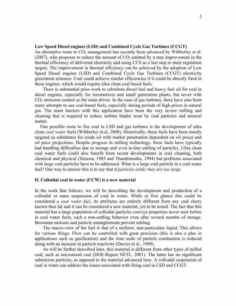
Additionally, Fig. 3 shows the results of the Nanotrac apparatus; the figure depicts the colloidal distributions, before and after the wet-comminution process. The conventional grind produces a colloidal population that is below 30 % weight and down to 0.7 – 1 µm, while the wet-comminution process increases the colloidal population up to 80 % and decreases size close to the nanorange (100 nm or 0.1 µm).
In our study, the percentage of mass passing the 635 mesh size sieve (< 20 µm) was used as an indicator of wet-comminution process efficiency, since microscopic observations showed that particles between 8 to 20 µm were very scarce. This process can attain virtually all-colloidal population when these characteristics are required, such as in gas turbines.
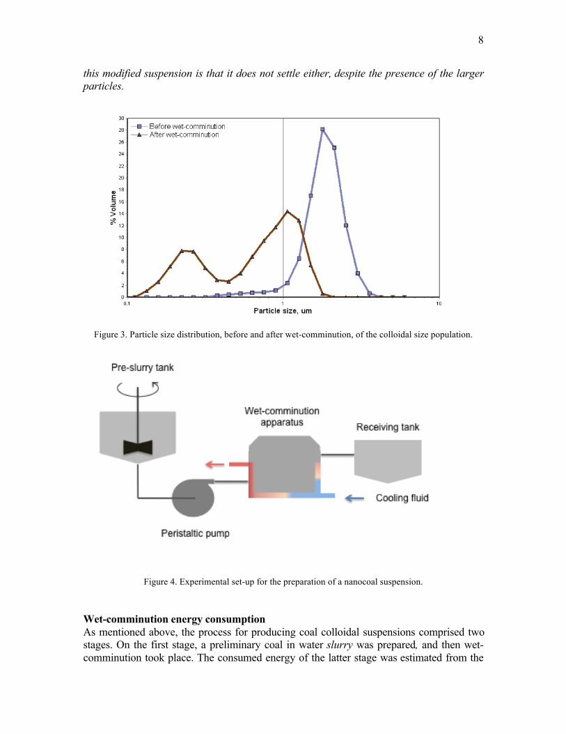
The preparation of the colloidal suspension of coal is centered in a technology that is totally based on fluid mechanics principles. As mentioned above, a preliminary suspension is prepared in a tank with low agitation with the appropriate water and surfactant contents. This suspension is then fed into a device that spins a film of the fluid to the walls of a cylindrical vessel at very high speed and under cavitation free conditions. The resulting flow field induces a “particle trap” region where coal particles are locally concentrated above their nominal value and under very high shear. Particles are then milled to very small sizes by a wet-comminution mechanism. Friction heating is controlled by a chilled water jacket around the vessel. A schematic view of the set up is shown in Fig. 4.
It is known that, for bidisperse suspensions the relative viscosity decreases significantly in comparison to that of a monodisperse suspension of the same material and the same solid volume fraction. As shown above, the particle size of the colloidal suspension is not bidisperse. However, the addition of a small fraction of particles in the 150 to 200 µm range has shown to reduce the suspension viscosity to the extent that water content can in turn be reduced by 10%, thus allowing for 70% coal in the suspension. A remarkable fact of
8
this modified suspension is that it does not settle either, despite the presence of the larger particles.
Figure 3. Particle size distribution, before and after wet-comminution, of the colloidal size population.
Figure 4. Experimental set-up for the preparation of a nanocoal suspension.
Wet-comminution energy consumption As mentioned above, the process for producing coal colloidal suspensions comprised two stages. On the first stage, a preliminary coal in water slurry was prepared, and then wet-comminution took place. The consumed energy of the latter stage was estimated from the

9
total motor amperage of the wet-comminution device, discounting the amperage measured when the apparatus is working in dry conditions (power consumed by the motor shaft and mechanical seal). The results of these measurements are presented in Fig. 5 in comparison form; our values take into account the power that would be necessary to run an industrial wet-comminution machine. Wet-ball mill energy consumption for milling Illinois Nº 6 coal are compared with wet-comminution of Eastern Bituminous coal and Guasare coal (from eastern Venezuela). The choice of these coals stems from the fact that they are similar, in terms of hardness and mineral matter content. As can be seen in the picture, the wet-comminution process consumes the same order of energy to produce colloidal particles that the ball mill uses for producing say, particles of 100 µm. This is an important result for any consideration of mass-production of CCW cheaply and in large quantities. This point will be addressed later.
Fig. 5. Comparative energy consumption as a function of mean particle size for coal wet ball mill and wet-comminution (Longlian et al., 2007). The legends indicate the concentration and type of coal used for each
process.
IV. Suspensions features The notion of a pseudo-fluid Probstein (1994) advanced a bimodal model for the viscosity of concentrated suspensions of colloidal and non-colloidal particles. The important feature of this model is that the colloidal fraction is assumed to act independently of the coarse fraction and to impart to a stable suspension most of its non-Newtonian characteristics, such as shear thinning behavior. Large particles are essentially unaware of the existence of the colloidal particles. Instead, they see a “stiffened” single-phase fluid with the same rheological behavior as the colloidal suspension.

10
If we recall the particle size distribution presented in Fig. 3 for the colloidal suspension of coal in water, even though the system is not bimodal, there exists a large colloidal fraction and a spectrum of sizes for non-colloidal particles. In essence, we could say this suspension is comprised of a large colloidal fluid made of submicron particles and water and non-submicron ones. The composite, water-colloidal particles, acts as a “pseudo fluid” in the sense that it behaves as one liquid phase that suspends the non-colloidal particles and impedes settling. We advanced long-term stability studies to confirm this notion and the results are presented next. Colloidal coal suspension stability The long-term stability of the samples prepared with the wet-comminution method was followed by observation of the samples homogeneity. This included detection of clarified water at the top and formation of a sediment layer. Clarification was evaluated by means of laser backscattering scans. The apparatus used for this purpose was a Turbiscan Model MA2000 made by Formulaction Corporation. A special glass vial containing the suspension sample is introduced in a chamber; a laser beam sweeps the vial from bottom to top. As it moves upwards, the laser travels along the sample up to the free surface. Receiving sensors collect back-scattered light, measured as a percentage of all the light intensity emitted.
To detect the formation of a sediment layer, a spatula was introduced in the sample, in a slow and vertical movement, up to the bottom of the jar containing the sample. The latter test only determined if a sediment layer was there, and no detection of sediment thickness or dispersability was intended (similar experiments have been carried out by Boylu et al., 2004). The same kind of tests was made for the samples in the special glass vials of the laser apparatus. Since these vials were narrow, a thin wire was then introduced to check for sediment formation.
Conventional coal slurries are very unstable to particle settling and most typical formulations must include stabilizers such as polymers or polymeric surfactants (Boylu et al., 2005; Boylu et al., 2004; Dinçer et al., 2003; Mishra et al., 2003; Tiwari et al., 2003; Ono, 2000). These stabilizers behave as dispersants to reduce flocculation leading to settling, or as rheological behavior modifiers inducing viscoplasticity or a yield stress. Another alternative to reduce settling is increasing the colloidal particle population (Chen et al., 2008; Ono, 2003). As mentioned before, sedimentation is prevented because the colloidal fraction behaves as a pseudofluid with a viscoplastic behavior that suspends large particles preventing their settling.
Changes of the colloidal coal and the conventional slurry were followed by laser backscattering scans, as already mentioned. Samples of both types of fluids were placed in vials containing about 7 mL of each type of sample. Repeated scans were performed, beginning at the moment the samples were poured into the vials, and continued until no more changes were detected in the scans spectra. The latter can be seen in Fig. 6(a) that also depicts both a photograph and a drawing of the vial (see legend for detailed explanation). The colloidal coal suspension was monitored until no more changes were observed (214 h). Only a very thin layer of water at the top of the sample was observed. Further, no sediment layer was detected using the thin wire, after a few weeks of storage.
The scans for the conventional slurry are shown in Fig. 6(b). This sample experienced a typical sedimentation pattern, i.e., gradual formation of a layer of clarified

11
water at the top that produced an increase of backscattering near the free surface (a ring of particles were trapped at the meniscus). The sample was monitored up to 121 hours. After that, no more significant changes were detected. A few weeks later, the thin wire test was performed and a thick layer of coal was detected at the bottom.
Figure 6. Transmission and backscattering scans for a) colloidal coal suspension, b) coal slurry. Solid content: 60 %. Room temperature. 1: rubber bottom; 2: colloidal suspension or slurry sample,
backscattering is about 10 %; 3: thin layer of clarified, clean water; 4: clarified water containing small coal particles; 5: ring of coal particles trapped in the meniscus.

12
Samples of colloidal coal suspension and conventional slurries were stored in large glass jars for follow-up. After months of storage, only a thin layer of water was observed at the top and no sediment was detected at the bottom. Conventional slurries had sedimented just a few hours after they were prepared. It is interesting to note that the colloidal coal suspension does not settle but experiences some water separation at the top, in a manner similar to the syneresis of a gel. It is as if the whole nanostructure shrank a little exuding some water. Viscosity of CCW dispersions The shear viscosity was evaluated using a rotational rheometer made by Rheometrics, model SR-2000, equipped with parallel plates. Figure 7 depicts the apparent viscosity as a function of shear rate (0.01 to 100 s-1) for a 60 % coal content colloidal suspension. The same kind of test was performed on conventional coal slurry, but sedimentation occurred during the measurement and the resulting flow curves were discarded. It can be observed that viscosity decays five fold and the high shear viscosity (100 s-1) reaches a value below 1 Pa.s. The colloidal suspension also exhibits a yield stress behavior.
The low shear viscosity is high because particle interactions build up due to the increase of the colloidal population. Forces between colloids induce the formation of large 3-D aggregates. However, high shear overcomes the interparticle forces and the size of the aggregates is reduced, thereby decreasing viscosity.
The colloidal coal suspension looked more viscous than the coal slurry. However, piping the suspension was an easier and more stable operation because no plugging and dynamic sedimentation occurred as for the pipe handling of conventional slurry. Pumping and tube flow of conventional slurry and colloidal coal suspension with 55 and 60 % coal content was monitored during the combustion tests described later in this paper. A Masterflex peristaltic pump and a custom plastic hose were used to convey the colloidal suspension and conventional slurry out of a 25 L container to the entry of the boiler nozzle, about 2 m downstream of the pump discharge. The pumping behavior was observed for several hours during combustion tests. The conventional slurry, unlike the colloidal suspension, produced frequent plugging that was only eased by increasing water content.
Further, the experimental evidence collected in a gravity driven capillary viscometer points to the fact that the colloidal coal suspension slips at the wall, once the yield stress has been overcome. The capillary viscometer was used to evaluate the flow behavior of polymodal, 68.5 % coal suspensions having particles too large (> 150 µm) to allow for the use of a rheometer. This device consisted of a 150 mL cylindrical container with a flush mounted glass, acrylic or PVC capillary at the bottom center. Several capillary lengths (33 to 65 cm) and diameters (5 to 12 mm) were used for a complete evaluation. The experimental procedure was as follows. The container and capillary were filled with sample, while blocking the capillary outlet. Then the outlet was open and the sample was allowed to run down to a receiving vessel while flow time was monitored by means of a chronometer. The amount of sample collected was later weighed.

13
Figure 7. Apparent viscosity as a function of shear rate for a colloidal coal suspension, 60 % coal.
Temperature: 25 ºC.
Shear stress τ was calculated as
€
τ =d ρs H + L( ) g
4 L (1)
where d is the capillary diameter, ρs is the suspension density, H is the height of sample in the container, L is the capillary length, g is the gravity acceleration (see Figure 8). It has to be noted that changes in H during a test were kept very small relative to L (ΔH << L), the capillary length.
The apparent shear rate,
€
˙ γ app , was calculated as
€
˙ γ app =32
ρs π d3mt
(2)
where m is the sample mass collected during time t. The apparent viscosity was then calculated as the ratio of shear stress over shear rate. Figure 8 shows shear stress as a function of apparent shear rate for a set of data (each point is the mean value of several tests). The viscosity of this 68.5 % polymodal suspension (large colloidal population plus particles > 150 µm) calculated from these data is about 500 to 600 mPa.s. The data collected with the 5 mm glass capillary does not follows the same trend and the reason why is discussed next.
The behavior of the samples during the test is worth recalling and discussing. Once the capillary outlet was unblocked, the samples tested in large diameter capillaries would pour out almost immediately. For the smaller capillary, no flow was observed at the first
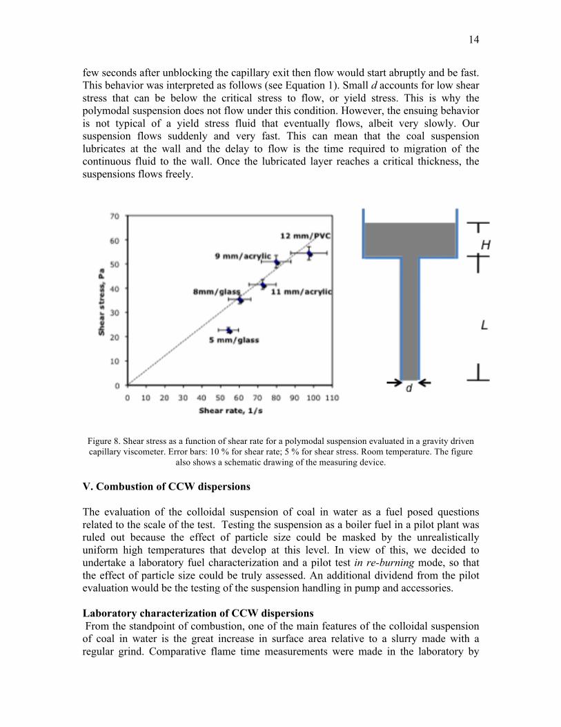
14
few seconds after unblocking the capillary exit then flow would start abruptly and be fast. This behavior was interpreted as follows (see Equation 1). Small d accounts for low shear stress that can be below the critical stress to flow, or yield stress. This is why the polymodal suspension does not flow under this condition. However, the ensuing behavior is not typical of a yield stress fluid that eventually flows, albeit very slowly. Our suspension flows suddenly and very fast. This can mean that the coal suspension lubricates at the wall and the delay to flow is the time required to migration of the continuous fluid to the wall. Once the lubricated layer reaches a critical thickness, the suspensions flows freely.
Figure 8. Shear stress as a function of shear rate for a polymodal suspension evaluated in a gravity driven capillary viscometer. Error bars: 10 % for shear rate; 5 % for shear stress. Room temperature. The figure
also shows a schematic drawing of the measuring device. V. Combustion of CCW dispersions The evaluation of the colloidal suspension of coal in water as a fuel posed questions related to the scale of the test. Testing the suspension as a boiler fuel in a pilot plant was ruled out because the effect of particle size could be masked by the unrealistically uniform high temperatures that develop at this level. In view of this, we decided to undertake a laboratory fuel characterization and a pilot test in re-burning mode, so that the effect of particle size could be truly assessed. An additional dividend from the pilot evaluation would be the testing of the suspension handling in pump and accessories. Laboratory characterization of CCW dispersions From the standpoint of combustion, one of the main features of the colloidal suspension of coal in water is the great increase in surface area relative to a slurry made with a regular grind. Comparative flame time measurements were made in the laboratory by

15
placing in a ceramic pan a sample of coal from the colloidal coal and coal with regular grind. The samples mass was varied from 180 to 750 grams of dry coal, either colloidal or conventional. Ignition was aided by the addition of a few drops of kerosene. Flame time was measured from its onset to total extinction. Figure 9 shows flame time in seconds for the colloidal coal and regular grind coal. Flame lifetime was almost double for the colloidal coal in approximately the whole range of dry coal mass evaluated.
Figure 9. Flame time of life as a function of coal mass for dry conventional coal grind and dry colloidal coal. Re-burning studies Reburning is a technology in which a fraction of the input fuel to a boiler is moved to a downstream location, establishing a fuel-rich reburning zone in which NOx emissions are reduced. At the pilot scale, this configuration can assess the benefits associated with the colloidal suspension new attributes, such as particle size, pseudo fluid characteristics and superior handling. To this end, we contracted GE-Energy to perform pilot scale reburning tests to define the NOx reduction and carbon burnout achieved with the suspension in their Santa Ana facility. In GE’s experience, the best way to run such tests is to comparatively evaluate a baseline fuel and a test fuel, thereby highlighting the potential benefits of the test fuel. Therefore, for the subject work GE performed reburning tests with both a conventional coal grind and the colloidal coal suspension of the same coal type. NOx reduction and carbon burnout were measured as a function of key reburning test parameters.
16
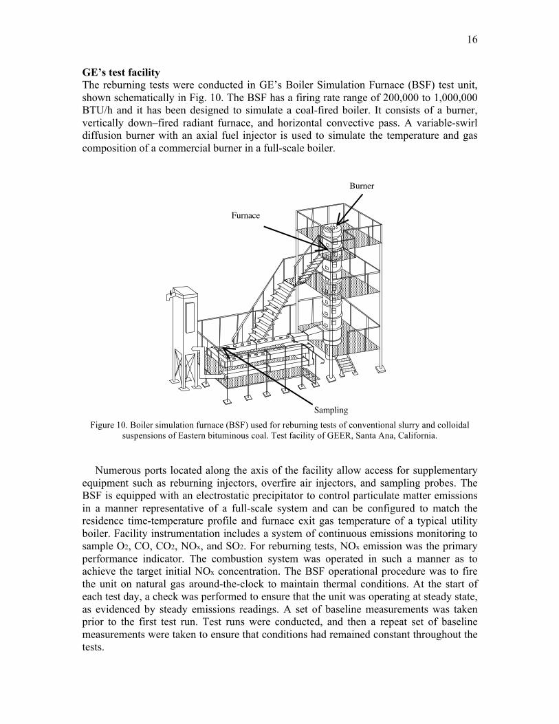
GE’s test facility The reburning tests were conducted in GE’s Boiler Simulation Furnace (BSF) test unit, shown schematically in Fig. 10. The BSF has a firing rate range of 200,000 to 1,000,000 BTU/h and it has been designed to simulate a coal-fired boiler. It consists of a burner, vertically down–fired radiant furnace, and horizontal convective pass. A variable-swirl diffusion burner with an axial fuel injector is used to simulate the temperature and gas composition of a commercial burner in a full-scale boiler.
Figure 10. Boiler simulation furnace (BSF) used for reburning tests of conventional slurry and colloidal
suspensions of Eastern bituminous coal. Test facility of GEER, Santa Ana, California.
Numerous ports located along the axis of the facility allow access for supplementary
equipment such as reburning injectors, overfire air injectors, and sampling probes. The BSF is equipped with an electrostatic precipitator to control particulate matter emissions in a manner representative of a full-scale system and can be configured to match the residence time-temperature profile and furnace exit gas temperature of a typical utility boiler. Facility instrumentation includes a system of continuous emissions monitoring to sample O2, CO, CO2, NOx, and SO2. For reburning tests, NOx emission was the primary performance indicator. The combustion system was operated in such a manner as to achieve the target initial NOx concentration. The BSF operational procedure was to fire the unit on natural gas around-the-clock to maintain thermal conditions. At the start of each test day, a check was performed to ensure that the unit was operating at steady state, as evidenced by steady emissions readings. A set of baseline measurements was taken prior to the first test run. Test runs were conducted, and then a repeat set of baseline measurements were taken to ensure that conditions had remained constant throughout the tests.
DOE Contract No. DE-FC26-00NT40912 Semiannual Report
2
superheater and economizer sections of a coal fired boiler. The facility has a baghouse at the end
of the convective pass to control fly ash emissions. Because it accurately simulates the thermal
environment of a full-scale boiler, the BSF is ideally suited to process optimization studies
leading to utility boiler application.
Furnace
Burner
Sampling
Figure 2 shows axial temperature profiles for the BSF. Temperature gradient was
adjusted to simulate environment in large-scale boilers.
1000
1300
1600
1900
0 0.5 1 1.5 2 2.5
Elapsed Residence Time (s)
Te
mp
era
ture
(K
)
Figure 1. Boiler Simulator
Facility (BSF).
Figure 2. Axial temperature
profile in BSF. Elapsed time
corresponds to the time after
injection of the reburning fuel.

17
Auxiliary systems The auxiliary systems used for the reburning tests were a slurry storage tank, continuous stirrer, peristaltic pump, slurry transport line, and twin-fluid atomizing nozzle. According to GE experience, high shear forces can cause slurries to separate during pumping, causing poor atomization and/or plugging of feed lines. Thus, a peristaltic pump was used to meter the coal water slurry, because this type of pump generates lower shear force than other devices such as gear pumps. Further, long transport line can cause slurries to separate, particularly when the lines are oriented upward. Therefore, the slurry storage tank was positioned as close to the atomizer as possible. This approach helped to shorten the slurry transport line. The slurry tank was equipped with a continuous stirrer to keep the slurry in suspension.
An in-house manufactured twin-fluid nozzle was use to inject the sample in the reburn zone. Most commercial nozzles tend to plug during coal slurry atomization. Compressed air joins with the injected slurry through a tube in a Y-shaped configuration jet, atomizing coal water slurry in numerous small droplets at the injection point. The superficial velocity of the atomizing air at the injection tip was estimated to be around 77 m/s, speed that would not cause the slurry to either impinge upon the furnace walls or be propelled up into the flame zone, either of which would artificially impact test results.
The atomization flow rate was held constant and the air-to-liquid mass ratio ranged from approximately 1.0 to 0.5 as reburn heat input varied from 10 to 20%. The ideal situation would be to hold both spray pattern and droplet size constant. However, this is not strictly possible when the liquid flow rate changes for different reburn rates. Functionally, droplet size typically decreases as atomization air flow rate (and air-to-liquid mass ratio) increases to a certain extent, and then levels off as additional air is added. The lower mass ratio evaluated, 0.5, is closer to the design point for this type of nozzle while the higher mass ratio, equal to 1.0 for the lower reburn rates, generally would not be expected to cause droplet size to decrease dramatically.
The method used was to run all points at the same atomization air flow rate, attempting to operate near the flat part of this curve. This approach was intended to maintain spray pattern while minimizing impacts on droplet size. Specific atomization tests would be needed for an in-depth quantification of these processes. Reburn fuel Eastern bituminous coal was used to prepare CCW dispersions and conventional coal water slurry that were the reburn fuels for the test program. The conventional grind had a size distribution such that approximately 70% of the material passed through an US 200 mesh sieve. Such a grind is typical for U.S. pulverized coal-fired boilers. The colloidal suspension was prepared by Nano Dispersion Technology and shipped to the GE facility at Santa Ana, California for reburn tests. The conventional coal water slurry was prepared at GE Santa Ana, California facility.
Test matrix Two series of reburning tests were performed, including one with colloidal coal water slurry and one with conventional coal water slurry. The slurry was the reburn fuel, with natural gas as the main fuel. After stable emissions were verified during natural gas

18
firing, slurry was pumped and atomized into the BSF furnace zone. NOx emissions were measured throughout the tests to determine the achievable NOx reduction. For selected test conditions, ash samples were collected from the convective pass of the BSF and loss on ignition (LOI) was measured.
Test variables included: • Reburning heat input (10 to 20%): Varied by adjusting the reburn fuel flow rate. • Reburn zone residence time (240 to 590 ms): Varied by moving the overfire air injector position. It is noted that varying the reburn zone residence time also varies overfire air injection temperature. • Initial NOx concentration (250 to 400 ppm): Varied by adjusting burner conditions. • Slurry water content (40 and 45%).
Qualitative assessment Based on the observation during reburn tests, GE made qualitative assessments of both colloidal and conventional coal water slurry. The colloidal slurry was prepared in Panama, shipped to Santa Ana, California, and was kept in storage for several weeks. Even after shipment and storage, it was found that the slurry did not settle in the containers and maintained good conditions. While detailed atomization studies were beyond the scope of the project, colloidal slurry characteristics with respect to handling, pumping and atomization were good.
The conventional coal water slurry was prepared at the GE Santa Ana facility with 40% water by weight. However, this slurry settled in the bottom of the storage container within a few hours. While GE did not perform a detailed quantitative analysis of slurry atomization, poor atomization quality and frequent plugging in the transport line was experienced with conventional slurry with 40% water. Even after making several modifications to the transport lines and flushing the reburn fuel injector and transport line, handling and atomization quality were poorer than for the colloidal slurry. To provide a more direct basis of comparison with the colloidal slurry, the conventional slurry was then prepared with 45% water by weight. Most conventional slurry reburning tests were performed with slurry containing 45% water. A few points with conventional slurry containing 40% water and colloidal slurry containing 45% water were completed and provided a reference basis for comparing results. Comparison with other reburn fuels A number of fuels have been utilized for reburning in the past. Natural gas was generally the preferred reburning fuel when this process was first developed. In subsequent development work, reburning has also been applied with other fuels such as pulverized coal. Figure 11 places the current coal-water colloidal suspensions reburning results in the context of other reburning fuels that have been tested at the BSF. Comparison fuels include natural gas and dry pulverized bituminous coal. Natural gas is the most reactive of these fuels due to its ability to readily disperse and react. However, natural gas is also typically the most expensive reburning fuel, and thus there is commercial interest in utilizing other fuels such as coal for reburning. The dry bituminous coal has relatively low volatile matter and high fixed carbon, and is not highly reactive. The colloidal suspension was generated using a bituminous coal that, on its own, would not be expected to be highly reactive. Its performance in reburning is nevertheless only
19
surpassed by natural gas. This has to do with the increased reactivity of the coal particles owing to their size and shows just a fraction of the potential this fuel can have.
VI. Some relevant questions
All evidence collected so far points to the surfacing of a new material for power generation. This material is not a slurry, as slurries have been known so far. Power generation is a delicate matter for the World. Many drivers are involved and some of them point in opposite directions. Of all drivers, two can be considered invariant in the foreseeable future. One is the continuous use of coal as fuel for power generation. As mentioned in the introduction this has to do with coal being cheap and abundant. The other driver is global warming.
In view of the foregoing, in what follows we advance some relevant questions concerning the massive use of colloidal coal suspensions in water for power generation. We have separated them into three types of questions. Mass production questions, Vision questions, having to do with potential applications and uses of the material in the future, and research questions. These have to do with particular issues that need to be addressed in the short term, which would open windows of opportunity for tangible clean coal applications.
Mass production questions The successful application of colloidal coal in water suspensions relies on its superior handling and combustion properties, as well as on a process capable of manufacturing large suspension outputs, at reasonable energy expenditure and additive costs. To assess the latter issue, we have evaluated the general steps associated with the mass production of the material. These are presented schematically in Fig. 11. In terms of specific energy required for mass-producing CCW, three stages are involved. First, raw coal must be milled to about 0.4 mm mean particle size (40 mesh), which is the requirement for preparing the coal in water slurry (plus additives) that is fed to the wet-comminution device. Commercial energy usage values to achieve this target particle size are about 10 – 12 kW h/ton (according to on-line publications of Xstrata Corporation, www.xstrata.com; Khodakov, 2007). The pre-slurry formation is carried out by regular mixing equipment and typically consumes less than 4 kW h/ton. As mentioned earlier, the wet-comminution process consumes about 120 kW h/ton of slurry leading to colloidal coal. If these factors are added, a figure of less than 150 kW h/ton is obtained, which is the same energy level most ball mills use to grind coal to about 80 to 100 µm.
Another point should be made here regarding colloidal coal. Advanced technology grinders, such as Xstrata Isamill™ can manufacture commercially micronized coal with great efficiency. However, this type of mills face difficulties going to submicron size because these “fines” (as people call very small particles in the mining industry) float in the air and become a health hazard, in addition to being very difficult to handle. Colloidal coal particles are better handled in the presence of water. That is also what makes CCW such a unique and new material, not to be confused with traditional coal water mixtures.
The second aspect for mass-producing CCW has to do with processing capacity. A commercial wet-comminution device has, typically, 16 L of vessel capacity and operates at residence times of less than five seconds. When scale-up factors are considered, a

20
manufacturing plant can be designed for a capacity of 500.000 ton/year of CCW with less than five units. These are not very large units and five devices can be accommodated in any industrial facility.
The third element associated with mass-producing CCW is very important and has to do with operational costs that include cost of raw coal (∼58 US$/ton), additives (10 US$/ton) and manufacturing (7 cents/kW.h) costs. The estimate for the production of a suspension containing 60 % of coal is about 3.2 US$/MBTU. The latter is reasonable.
Fig. 11. General process for manufacturing CCW. Vision questions As pointed out by Ansolabehere et al. (2007), “CO2 capture and sequestration is the critical enabling technology that would reduce CO2 emissions significantly while also allowing coal to meet the World’s pressing energy needs “

21
Within this context, ultra supercritical boilers, various combined cycle gasification schemes and oxy-combustion are the most important and promising technologies being evaluated and used today. While these initiatives are fine, a long-term vision for coal might require a paradigm shift, like producing electricity in distributed configurations with greater thermal efficiency as a standard. What if coal is utilized with virtually no CO2 emitted? Firing coal in more efficient devices such as low speed diesel engines, gas turbines and even fuel cells could greatly reduce CO2 emissions. As already mentioned, all of these applications require various degrees of coal cleaning. Now, coal cleaning is not a new activity but treating coal so that it can be used in a direct carbon conversion fuel cell (DCC) is (Cooper, 2004). The same applies; albeit to a lesser extent, to gas turbines and diesel engines.
Figure 11. Comparison of reburn performance for various fuels, including conventional coal slurries having
40 and 45 % water, and colloidal coal suspensions obtained by means of the wet-comminution process.
Deep coal treatment for DCC involves the reduction of ash and pyrite by mechanical and chemical means to less than 1%. Similar targets are required for gas turbines and to a certain extent, to diesel engines. All coal-cleaning strategies are affected by particle size. Surface treatments are strongly impacted by surface area and flotation forces depend directly on particle size. Colloidal coal could represent a big step in improving deep coal cleaning. It could facilitate the removal of mineral matter within the wet-comminution process and help in surface treatments. How this product can be incorporated into coal cleaning procedures is an important question in the quest for enabling the use of coal in the future.
22
Coal cleaning is a required step but not the only one. Efficient energy conversion is another, which is associated with something that can be called fuel preparation. Colloidal coal can be viewed as a form of fuel preparation. Fuels need to be handled and must be the right fit for the conversion device being used. Sekar et.al (1992) tried to fire low-grade diesel fuel in a diesel engine with oxygen enrichment and water. Their idea was to reduce NOx and particulates by firing with water modulating the high temperatures associated with oxygen enrichment. Colloidal coal could be used in a low-speed diesel engine in the presence of oxygen with great efficiency. Fuel injection control would be greatly improved relative to any slurry by the homogeneous nature and rheological behavior of CCW. The same situation could apply to a gas turbine. For the case of DCC, the match with CCW is yet to be determined but could yield great benefits.
We have made arguments concerning CCW in low-speed diesel engines, gas turbines and even fuel cells, but colloidal coal could also benefit gasification schemes and oxy-combustion. Integration of gasification into the total IGCC plant imposes additional considerations on the technology (Holt et. al. 2003). Moving bed gasification, for example, cannot deal with a significant fraction of coal fines, which means that 20 – 30 % of the processed coal cannot be fed into it.
A question then arises as to the potential impact of CCW in this technology. High temperature, entrained-flow gasifiers do not have these issues and are thus more readily integrated into an IGCC system. High-pressure operation is favored in these units. The introduction of coal into a pressurized gasifier can be done either as dry coal feed through lock hoppers of by slurrying the finely ground coal with water and spraying it into the gasifier. The latter introduces 30 % w/w liquid water, which is desirable if the coal has low moisture content. For high moisture content the gasifier feed can approach 50 % water, which increases the oxygen required to gasify the coal and vaporize the water and reduces the overall operating efficiency. Colloidal coal could enter into this technology in two ways. For low moisture coal it would facilitate handling and flow control into the gasifier by virtue of its non-settling attribute. In the case of high-moisture coal, the very process of wet-comminution could contact and extract some of the water present in the coal and maintain water levels close to 30% or less, avoiding the efficiency de-rating.
In oxy-combustion schemes, CCW could have an impact as a result of the increased reactivity associated with small particles. That, in turn, could change the amount of oxygen required for optimum operation with re-circulated flue gas. Research questions The use of colloidal coal poses many specific questions that require research efforts. The main set of questions involves making CCW usable in diesel engines and gas turbines. Table 1, after Wibberley (2008), lists current specs necessary for using coal water fuels in these machines. The colloidal coal suspension advanced here is not far from meeting these specs within reasonable cost. However, many questions emerge from this table.
• For colloidal coal, would the particle size shown in the table be really required? • Wouldn’t the colloidal particles greatly enhance the reactivity of larger particles? • What are the detailed combustion characteristics of CCW? • Would coal in colloidal form require deep cleaning? • What would be the ideal water content for a colloidal coal suspension to be used in

23
gas turbines and diesel engines? Research questions also emerge from gasification and oxy-combustion applications. Based on the previous discussion the following are specific areas that need be assessed,
• Can CCW be applied in a moving-bed gasifier? • Would the wet-comminution process contact and extract water present in high-
moisture coal? • What is the impact of overall operating efficiency in a gasifier as a result of
improved flow control using CCW? • Can CCW optimize the water content into the gasifier without increasing the
viscosity of the suspension? • Can CCW help reduce the amount of oxygen required in an oxy-combustion
scheme? Given the prominence given by many industrial nations to IGCC to reduce greenhouse
gases, the foregoing questions are of great importance and are also potential good opportunities to improve these processes. Table 1. Current specs for coal water fuels according to the application (Wibberly, 2008).
Property Current CWF for boilers
Gas turbine Diesel engine
Mean particle size,
µm 10-20 4-6 5-15
Particle size, µm % mass passing
-5 µm 5 60 30 -10 µm 35 100 60 -20 µm 50 100 -75 µm 75 -250 µm 95 -500 µm 100
Coal content, %
w/w 65-70 55-60 50-55
Viscosity, mPa.s @ 100 s-1 500-1000 400 300
The evidence presented here shows colloidal coal in water is not an idea but a reality. As a consequence, we are persuaded the foregoing questions must be addressed in the near future.
24
VII. A remark on scale-up Any commercial application involving the use of CCW would require the manufacture of large volumes of the product. As mentioned earlier, the wet-comminution process takes place in a hydrodynamically induced fluid region that “traps” the particles and subjects them to high shear. This region is confined to a film and the film can be reproduced at large scales with the same dynamic conditions. This is what ensures scale up success. When scaling up a regular mixer, shear levels and specific energy inputs are hard to reproduce at larger scales from, say, a lab condition. This does not happen with the wet-comminution technology described here. Another interesting feature of this technology is that it is very fast. Residence times tend to vary with the material being processed but are seldom greater than 10 seconds. Again, that stems from the hydrodynamic focusing, which traps particles and mills them by contact forces in a short time. The combination of short residence time with hydrodynamic focusing allows for an easy change of scale and facilitates large production of CCW. VIII. Concluding remarks We have advanced a colloidal coal in water suspension that has features never seen before, such as long-term stability to settling. This material has already many applications that could open new doors for using coal in a non-pollutant manner. Some applications may even be still unknown. This work also poses research and vision questions that if answered, could impact greatly the way we produce electricity today. Acknowledgments We are grateful for the invaluable help of Alonso Alvarado, Edgar Marin and Francisco Chang who carry out some of the experimental work. We are also grateful to Prof. L.S. Fan for reading an earlier draft of this paper with a critical eye. The work of D.D. Joseph was supported, in part, by the applied math division of the NSF, under ARRA. List of Acronyms BSF: Boiler Simulation Furnace CCGT: Combined Cycle Gas Turbines CCS: CO2 capture and sequestration CCW: Colloidal coal in water suspensions DCC: Direct carbon conversion fuel cell IGCC: Integrated Coal Gasification Combined Cycle LOI: Loss on ignition LSD: Low Speed Engines USC: Ultra Super Critical Pulverized Combustion References Ansolabehere S, Beer J, Deucht J, Ellerman D, Katzer J, Friedman J, Herzog H, Jacoby,

25
H., Joskow, P., Mcrae, G., Lester, R., Moniz, E., Steinfeld, E. 2007. The Future of Coal: Options for a Carbon-Constrained World. MIT Press. Boylu F, Atesok G, Dincer H. The effect of carboxylmethyl cellulose (CMC) on the stability of coal-water slurries. Fuel, 84, 315-319 (2005). Boylu F, Atesok G, Dincer H. Effect of coal particle size distribution, volume fraction and rank on the rheology of coal–water slurries. Fuel Processing Technology, 85, 241– 250 (2004). Cheng J, Zhou J, Li Y, Liu J, Cen K. Effects of pore fractal structures of ultra fine coal water slurries on rheological behavior and combustion dynamics. Fuel, 87, 2620-2627 (2008). Cooper J. Direct conversion of coal and coal-derived coal cells in fuel cell. Presentation to The Washington Coal Club, (2004). Davis KA, Valentine JR, Eddings EG, Heap MP. Evaluating the effects of low-NOx retrofits on carbon in ash levels. Reaction Engineering International. Mega Symposium: EPRI-DOE-EPA, Combined Utility Air Pollutant Control Symposium, Atlanta, August 16-20, 1999. Dinçer H, Boylu F, Sirkeci A, Atesok G. The effect of chemicals on the viscosity and stability of coal water slurries. International Journal of Mineral Processing, 70, 41– 51 (2003). Harrison C, Akers D, Maronde C. Fuels technology update. US-DONETL Report, Feb. (2002). Holt N, Booras G, Todd D. Summary of recent IGCC studies of CO2 capture and sequestration. MIT Sequestration Forum IV. Cambridge, Mass. (2003). Khodakov GS. Coal-water suspensions in power engineering. Thermal Engineering, 54(1), 36-47 (2007). Mishra SK, Kanungo SB, Rajeev. Adsorption of sodium dodecyl benzene sulfonate onto coal. Journal of Colloid and Interface Science, 267, 42–48 (2003). Longlian C, Liqian A, Gong W, Hejin J. A novel process for preparation of ultra-clean micronized coal by high pressure water jet comminution technique. Fuel, 86 (5-6), 750-757 (2007). Ono T. Improved Coal Pulverization Method Using the Embrittlement due to Cracks Generated in Pores of Coal. Kona, 212, 202-207 (2003). Ono T. High-concentration coal/water mixture fuel and process for production thereof. US Patent 6,083,286, 2000. Probstein R.F. In chapter 9, pp. 298, second edition. Physicochemical Thermodynamics. Wiley Interscience, New York, 1994. Simeon J. Economical potential of coal-water mixtures. ICEASIE 8, London, UK. IEA Coal Research, September 1985. Sekar RR, Marr WW, Schaus JE, Cole RL, Marciniak TJ. Diesel engine experiments with oxygen enrichment, water addition and lower-grade fuel. Energy Conversion Engineering Conference. Proceedings of the 25th Intersociety. Volume 4, Issue 12-17, Aug 1990, 320 - 325.

26
Thambimuthu. Developments in coal-liquid mixtures. Center for applied Energy Research, Report 69, 79 pages (1994). Tiwari K, Basu S, Bit K, Banerjee S, Mishra K. High-concentration coal-water slurry from Indian coals using newly developed additives. Fuel Processing Technologies, 85, 31-42 (2003). Wibberley L., Palfreyman D., Scaife P. Efficient use of coal water fuels. CSIRO Energy Technology (2008). US Department of Energy, National Energy Technology Laboratory. Micronized coal reburning demonstration for NOx control: a DOE assessment. Report DOE/NETL 2001/1148, agosto, 2001.