
Collision Avoidance for Naval Training Aircraft - ll.mit.edu · PDF fileProject Report ATC-125...
40
Lincoln Laboratory MASSACHUSETTS INSTITUTE OF TECHNOLOGY LEXINGTON, MASSACHUSETTS Project Report ATC-125 Collision Avoidance for Naval Training Aircraft J. W. Andrews Raymond R. LaFrey Jerry D. Welch 8 March 1985
Transcript of Collision Avoidance for Naval Training Aircraft - ll.mit.edu · PDF fileProject Report ATC-125...
Lincoln Laboratory MASSACHUSETTS INSTITUTE OF TECHNOLOGY
LEXINGTON, MASSACHUSETTS
Project ReportATC-125
Collision Avoidance for Naval Training Aircraft
J. W. AndrewsRaymond R. LaFrey
Jerry D. Welch
8 March 1985

This document is disseminated under the sponsorship of the Department of Transportation in the interest of information exchange. The United States Government assumes no liability for its contents or use thereof.
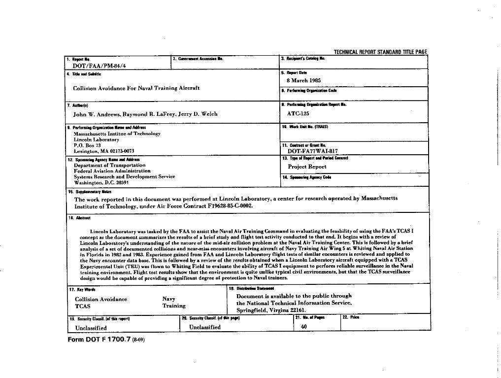
TABLE OF CONTENTS
COLLISION AVOIDANCE FOR NAVAL TRAINING AIRCRAFT
TRE NAVY TRAINING COMMAND COLLISION PROBLEM
LINCOLN ~ORATORY MISSION TO NRITING
ENCOUNTER DATA BASE ANALYSIS
DISTRIBWION OF ENCOUNTER CLOSING SPEEDS AND BEARINGS
FATAL ENCOUNTERS
EXPERIENCE FROM FAA/LINCOLN TCAS FLIGHT TESTS
VISUAL ACQUISITION RANGES
EXAMPLE OF TRAFFIC ADVISORY DISPLAY
RECOWNDATIONS FROM ENCOUNTER DATA BASE ANALYSIS
TCAS PERFORMANCE IN NAVAL TRAINING ENvIROWNT
TCAS FLIGHT TEST AT NRITING FIELD
PROPOSED A~WGE PONER LWITS FOR TCAS I
PERFORMANCE OF TCAS AS A FUNCTION OF TRANSMIT PONER
PROPOSED DESIGN OF NAVY TCAS
C421 - T34 ENCOUNTER
AIRCRAFT INSTALLATION CONSTRAINTS
s~Y
1
2
4
6
8
10
12
14
16
18
20
22
24
26
28
30
32
34
iii

,.
COLLISION AVOIDANCE FOR NAVAL ~INING AIRCRAFT
Lincoln hboratory was tasked by the FAA to aasist the Naval Nr Training Comand inevaluating the feasibility of using the FAA’s TCAS I concept as the basis of a collision avoidancesystem for Naval training aircraft. ~is document su~rizes the results of a brief study andflight test activity conducted to that end. It begins tith a review of Lincoln hborato~’sunderstanding of the nature of the tid-air collision problm at the Naval M r Training Center.This is followed by a brief analysis of a set of documented collisions and near+ss encountersinvolving aircraft of Navy Training Air Wing 5 at Whiting Naval Air Station in Florida in 1982 and1983. Experience gained from FM and Lincoln tiboratory flight tests of similar encounters iareviewed and applied to the Navy encounter data base. This is followed by rwiew of the resultsobtained when a Lincoln tiboratory aircraft equipped tith a TCAS Experimental Unit (TEU) was flown
to Whiting Field to evaluate the ability of TCAS I equipment to perfom reliable surveillance inthe Naval training envirouent. Flight test results show that the environment is quite unlike
typical civil enviroment~, but that the TCAS surveillance design would be capable of providing asignificant degree of protection to Naval trainers.
1
T~ NAW TSAINING C~ COLLISION ~OBLEM
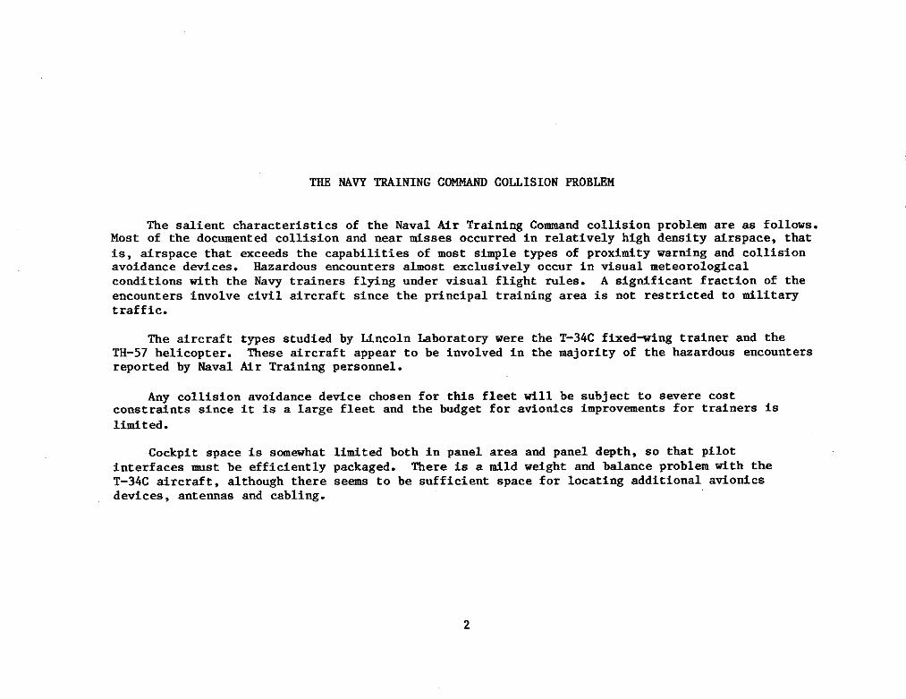
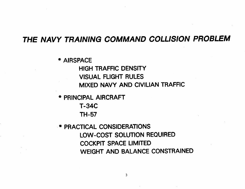
The salient characteristics of the Naval Air Traiting Comnd collision problm are as follows.Most of the documented collision and near misses occurred in relatively high density airspace, that
is, airspace that exceeds the capabilities of most simple types of profitity warning and collisionavoidance devices. fizardous encounters almost -elusively occur in visual meteorologicalconditions with the Nawy trainers flying under visual flight riles. A significant fraction of theencounters involve civil aircraft since the principal training area is not restricted to tilitsrytraffic.
The aircraft types studied by Lincoln Laboratory were the T-34C fixed-ing trainer and theTH-57 helicopter. Tb&e aircraft appear to be involved in the majority of the hazardous encountersreported by Naval Air Treini~ personnel.
Any collision avoidance device chosen for this fleet will be subject to severe costconstraints since it is a large fleet and the budget for aviotics improvements for trainers is
lid ted.
Cockpit space is somwhat litited both in panel area and panel depth, so that pilotinterfaces mst be efficientlY packaged. There is a tild weight ad balance problm with the
T-34C aircraft, although there sema to be sufficient apace for locating additional avioticsdevices, antennaa and cabling.
2
THE NAVY TRAINING COMMAND COLLISION PROBLEM
* AIRSPACE
HIGH TRAFFIC DENSITYVISUAL FLIGHT RULESMIXED NAVY AND CIVILIAN TRAFFIC
* PRINCIPAL AIRCRAFTT-34C
TH-57I
* PRACTICAL CONSIDERATIONS
LOW-COST SOLUTION REQUIREDCOCKPIT SPACE LIMITEDWEIGHT AND BALANCE CONSTRAINED
3
LINCOLN LAWORATORY MISSION TO WRITING
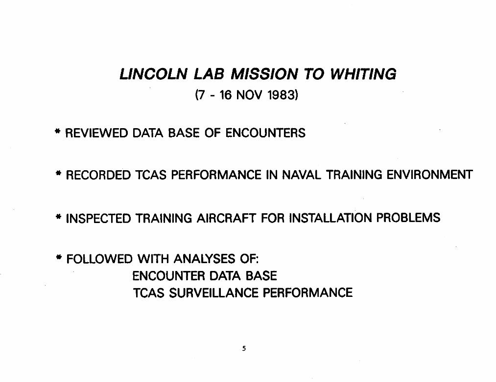
A conti~ent of Hncoln Laboratory personnel visited the Ncval Mr Station at Whiti~ Field thesecond week of Novmber 1983 to obtain a first-hand assessment of the collision probla and the
conditions under wMch a collision avoidance ayatm for NSW trainera would have to operate.Several distinct activities were carried out during and after t~s trip. A data bate of 31
encounters includi~ hazardous near tid-air collisions and three fatal encounters was abstractedfrom records collected by Naval fiaining &r Wing 5 at Whiting Field.
A Uncoln bborato~ Arcraft equipped with a T~S tiperimental Unit was flon to WhitiW Fieldand participated in typical training wneuvers tith Naval Flight iwt rectors as copilots. This
aircraft made cmplet e recordings of the tirborne transponder intarrogation ad reply environmentfor subsequent analyaia. These recordings occurred over a period of approximately eight hunrs, adincluded periods that Naval personnel judged to be characteristic of the highest aircraft densitiesto be qected in the traini~ area.
Lincoln personnel inspected tbe T34< and TW-57 d rcraft for potential installation andantenna shieldi~ probl-.
The visit was followed by an amlysis of the Trdting &r Wing 5 encounter data base, anamlysis of the traffic environment recorded by the ~S &perimental Unit, and a study of the
=pect ed surveillance perfomance of an appropriate TMS design in the traini~ environment.
LINCOLN LAB MISSION TO WHITING
(7 -16 NOV1983)
* REVIEWED DATA BASE OF ENCOUNTERS
* RECORDED TCAS PERFORMANCE IN NAVAL TRAINING ENVIRONMENT
* INSPECTED TRAINING AIRCRAFT FOR INSTALLATION PROBLEMS
* FOLLOWED WITH ANALYSES OF
ENCOUNTER DATA BASETCAS SURVEILLANCE PERFORMANCE
5
.. -——— . . ..—
ENCO~ER DATA BASE HYSIS
fie 31 encounters that were a=lyzed all occurred in 1982 and lg83. me nOn-fatal encounters
occurred between Januag 1983 and the date of the fincoln visit. In order to obtain more data onfatal encounters, the fatal encounters from 1982 were also included in the data h=e. U1 of the
encounters occurred in the Nhiting Field training area. The three that were fatal all involvedpairs of T-34Ca. One of the fatal encounters did not involve an actual cOllisiOn, but rather anear collision which induced a severe wneuver leading to a low-altitude stall and aubaequent
crash.
Nineteen of the encounters involved pairs of T-34CS. ~elve of the encounters involved civilaircraft. Of those civil aircraft, ody four were light ai~le-engine aircraft of a type that
tight not be equipped tith altitude-reporting transponders. The other eight were all either ttinaOr jets and were most likely equipped for altitude reporting. The four encounters involving
~-57s were all tith non-jet-transport civil aircraft. There was one encounter between a T-34C
and a jet tranaport sircraft.
The mximum closiw speed estimated for the 31 encounters was about 390 kt. me most
cowonly reported closing speed was about 200 kt. Moat of tbe encounters occurred such that theintmder was tithin the field of view of the trainer pilot. (The n=t page provides detailed
distributions for these statistics. )
The probable cause for moat of the hazardoua incidents was ftilure of the trainer pilot to aee
the other aircraft in time. In some casea, t~s ftilure occurred because of the presence of othertraffic. In one case, there was an apparent tisunderatanding between the pilot and the grOundcontroller. In at least one of the incidents the pilot fdled to visually clear the local airspaceprior to ititiati~ an acrobatic maneuver. In general, it appears that reliance on unaided visual
search to detect the presence of nearby hazardoua aircraft is often ineffective in the Naval ~rtraifing environment. The unexpected nature of encounters tith civil cfrcraft may be a factor in
this breakdo-. kong factors that do not appear to be aigfificant, are weather, high closing$ speeds, or equipent ~lfunctiO~.
It ia significant in the context of auto~tic collision avOidance equi~ent that a larges
[ fraction of the encounters occurred in drapace where there were mltiple aircraft tithin visual
[range. ~is implies that a simple proximity warning would not be enOugh. me PilOt ~st be
I
assisted in identifyi% and aorti~ out ~ltiple aircraft ad, if pOssible, in dete~ning whichaircraft is the moat threatening at any instant.
6
.
*
*
*
*
*
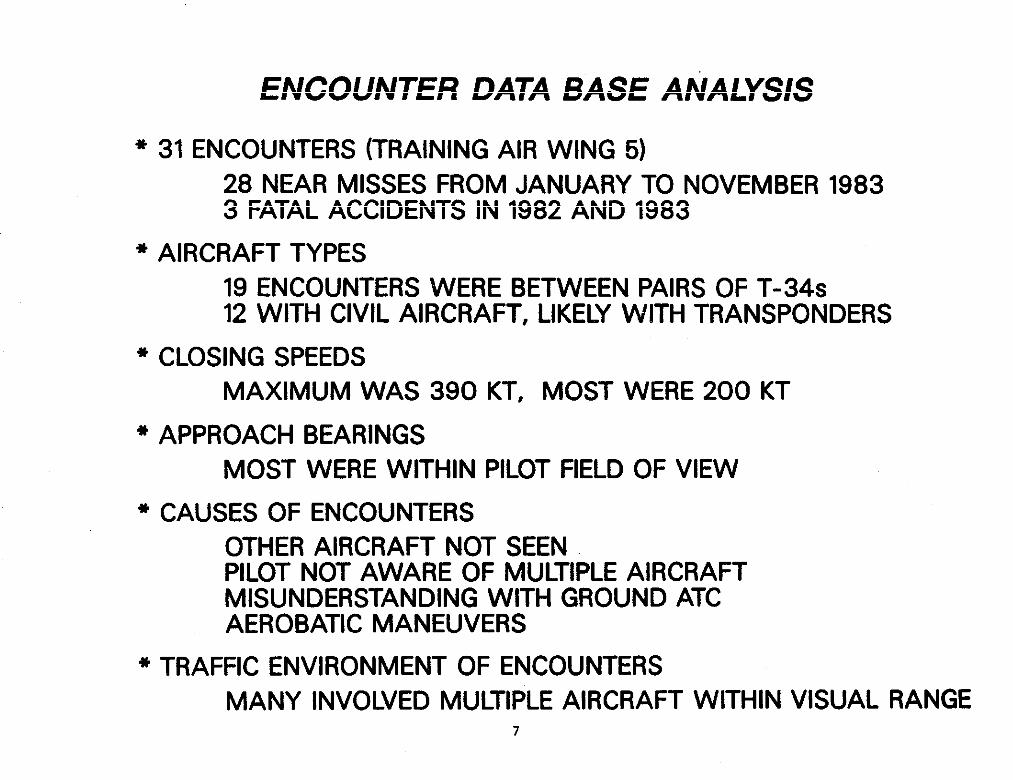
ENCOUNTER DATA BASE ANALYSIS
31 ENCOUNTERS (TRAINING AIR WING 5)
28 NEAR MISSES FROM JANUARY TO NOVEMBER 19833 FATALACCIDENTS IN 1982 AND 1983
AIRCRAFT TYPES19 ENCOUNTERS WERE BETWEEN PAIRS OF T-34s12 WITH CIVIL AIRCRAFT, LIKELYWITH TRANSPONDERS
CLOSING SPEEDSMAXIMUM WAS 390 KT, MOST WERE 200 KT
APPROACH BEARINGSMOST WERE WITHIN PILOT FIELD OF VIEW
CAUSES OF ENCOUNTERSOTHER AIRCRAFT NOT SEENPILOT NOT AWARE OF MULTIPLE AIRCRAFTMISUNDERSTANDING WITH GROUND ATCAEROBATIC MANEUVERS
TRAFFIC ENVIRONMENT OF ENCOUNTERSMANY INVOLVED MULTIPLE AIRCRAFT WITHIN VISUAL RANGE
7 I
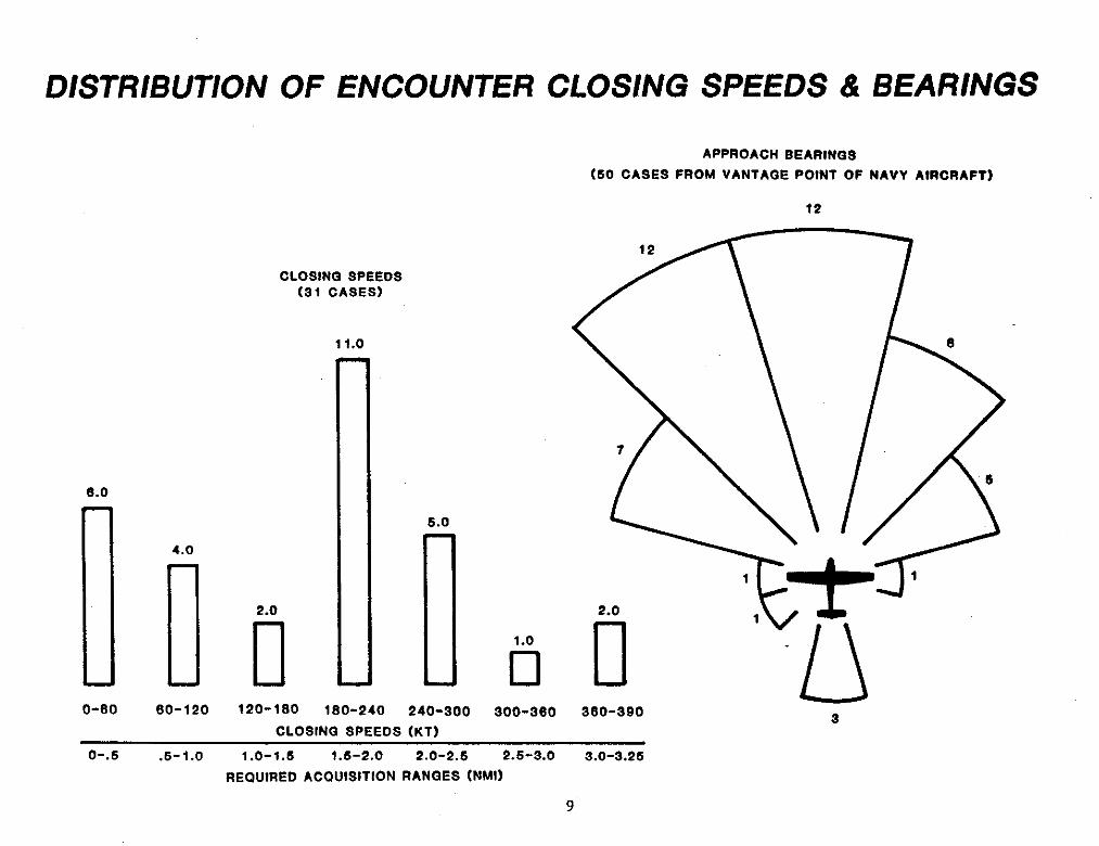
DIS~IBUTION OF ENCO~ER ~OSING SPEEDS AND BWINGS
me distributions of the approximate closing speeds and approach bearings of the 31encounters are shown. me required suneillance detection range for a 30-second warning time is
also shown for each value of closing speed in the tistogrm. A mzimum detection range of 3.5 d
would have been adequate for each of the 31 cases studied.
me distributions of approach bearings for the detected aircraft are also shown from thevantage point of the 50 Na~ aircraft involved in the 31 encounters. It is seen that only three of
the approachi~ Arcraft would have been outside of the no-l field of view of the crew.
8
DISTRIBUTION
6.0
0-60
4.0
60-120
OF ENCOUNTER CLOSING SPEEDS & BEARINGS
CLOSING SPEEDS(S1 CASES)
11.0
2.0
120-180 1S0-240
6.0
1
240-300
1.0
❑900-s60
APPROACH SEARINGS
(60 CASES FROM VANTAGE POINT OF NAVY AIRCRAFT)
12
2.0
n
A-- ]1
3s0-390 aCLOSING SPEEOS (KT)
o-.6 .5-1.0 1.0-1.s 1.6-2.0 2.0-2.6 2.5-s.0 s.0-3.25
REQUIRED ACqUiSitiOn RANGES (NMI)
9
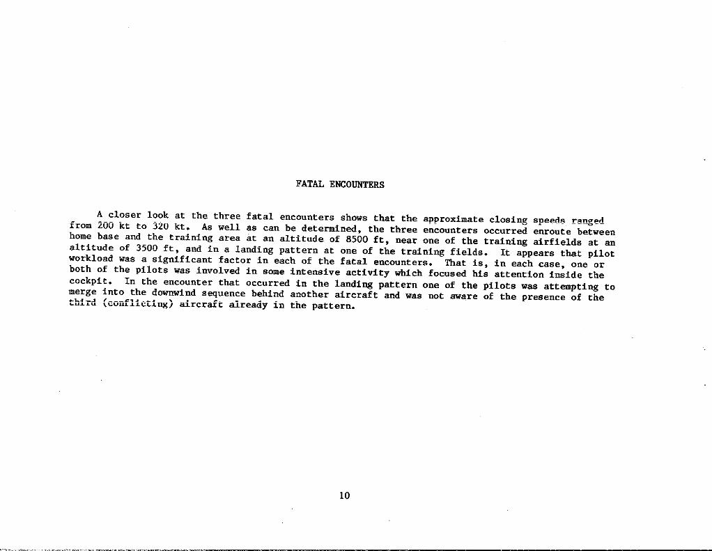
FATAL ENCO-RS
A closer look at the three fatal encounters shows that tk approximate closing speeds rangedfrom 200 kt to 320 kt. As well as can be detetined, the three encounters occurred enroute betweenhome base and the training area At an altitude of 8500 ft, n-r one of the traifi~ drfields at analtitude of 3500 ft, and in a landing pattern at one of the traini~ fields. It appears that pilotworkload waa a significant factor in each of the fatal encounters. That is, in each case, one orboth of the pilots was involved in some intensive activity +ich focused his attention inside the
cockpit . In the encounter that occurred in the landi~ pattern one of the pilots was attmpting tomerge into the dmwind sequance betind another tircraft and was not aware of the presence of thethird (conflicting) sfrcraft already in the pattern.
I
i1
I
10
i .=w,~~ -‘-’--““war***.,.,... ... ......................... ., . . &..i.,.,._. ,...:,,.,..,....;.< ,.=: ,,, ,Rx:,..<...,.,.. ,.,.,,;*7,. . ... . ... ..... ,..,.,, ..../,, .... . ... ... :...* ...... .. . . .. . . ,=-... ...-=.>.. y.. . . . . . .... ..F.--* . . .. .... ... ... - -. .,..$- ..?, .,~:. !. .. . . .. .. . . ..
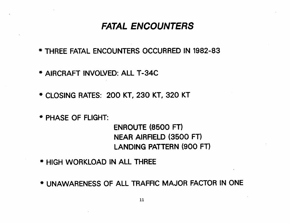
FATAL ENCOUNTERS
* THREE FATAL ENCOUNTERS OCCURRED IN 1982-83
It * AIRCRAFT INVOLVED: ALL T-34CI
i~ * CLOSING RATES: 200 KT, 230 KT, 320 KTi1
* PHASE OF FLIGHTENROUTE (8500 FT)NEAR AIRFIELD (3500 FT)LANDING PATTERN (900 ‘FT)
k{
* HIGH WORKLOAD IN ALL THREEi~E*i:,~[ * UNAWARENESS OF ALL TRAFFIC MAJOR FACTOR IN ONE
I1
11

EXPERIENCE FROM FAA/LINCOLN TCAS FLIGHT TESTS
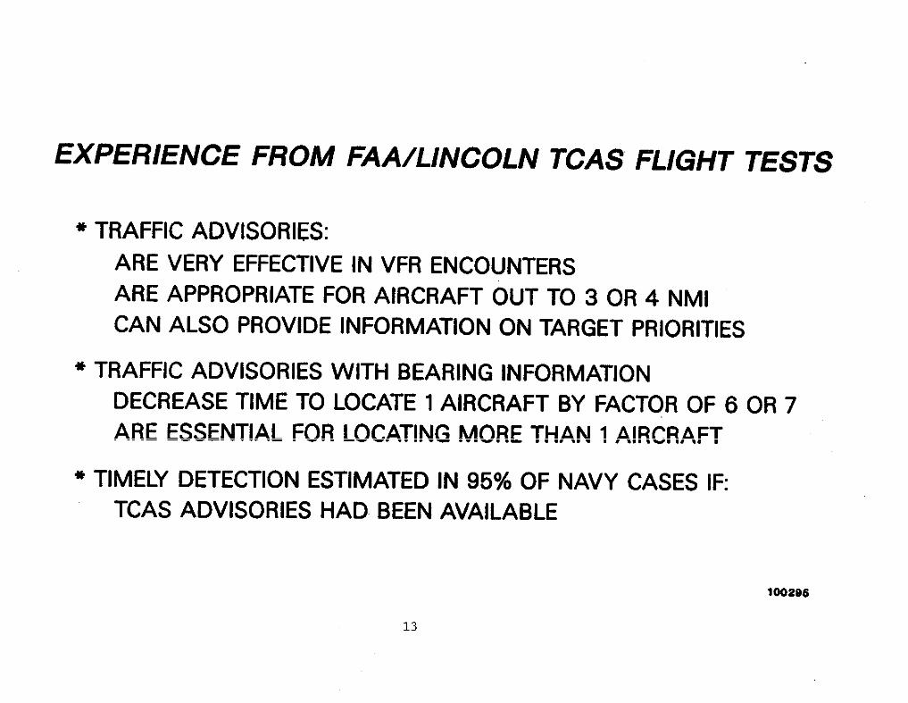
* TRAFFIC ADVISORIES: 1
ARE VERY EFFECTIVE IN VFR ENCOUNTERS
ARE APPROPRIATE FOR AIRCRAFT OUT TO 3 OR 4 NMICAN ALSO PROVIDE INFORMATION ON TARGET PRIORITIES
* TRAFFIC ADVISORIES WITH BEARING INFORMATION!! DECREASE TIME TO LOCATE 1 AIRCRAFT BY FACTOR OF 6 OR 7
ARE ESSENTIAL FOR LOCATING MORE THAN 1 AIRCRAFT
* TIMELY DETECTION ESTIMATED IN 95% OF NAVY CASES IF:TCAS ADVISORIES HAD BEEN AVAILABLE
3
100206
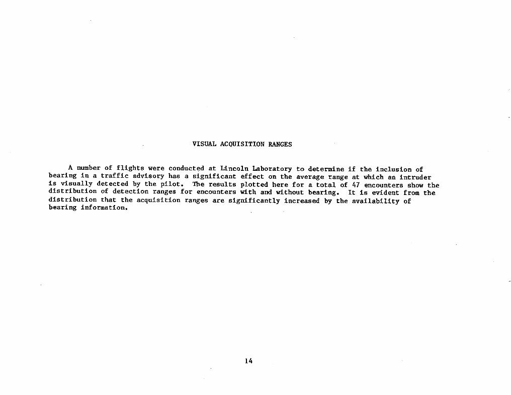
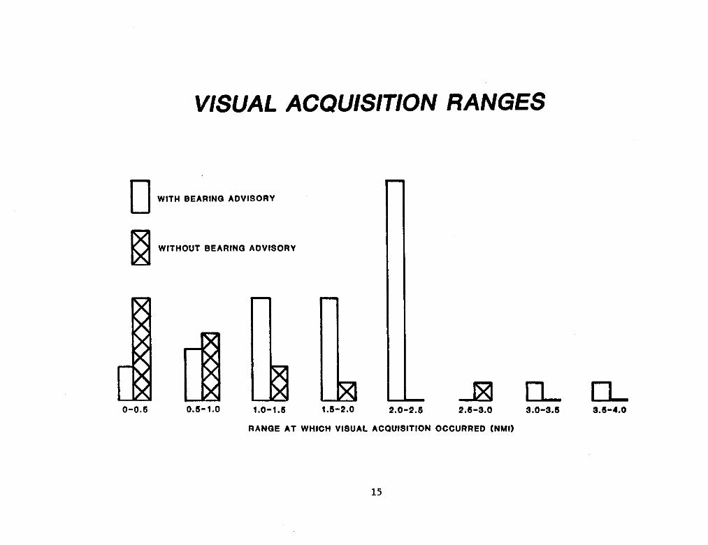
VISUU ACQUISITION SANGES
A number of flights were conducted at Mncoln kborat ory to detetine if the inclusion ofbearing in a traffic advisory has a significant effect on the average range at w~cb an intmderis visually detected by the pilot. The results plotted here for a total of 47 encounters show thedistribution of detection ranges for encounters tith and tithout bearing. It is evident from the
distribution that the acquisition ranges are significantly increased by the availability ofbearing information.
14
VISUAL ACQUISITION RANGES
nWITH BEARING ADVISORY
EWITHOUT BEARING ADVISORY
.
1P0-0.6 0.s-1.0 1.0-1.6
RANGE AT WHICH VISUAL ACQUISITION OCCURRED (NM!)
1.6-2.0 2.0-2. s 2.6-3.0 3.0-3.6 S.6-4.0
15
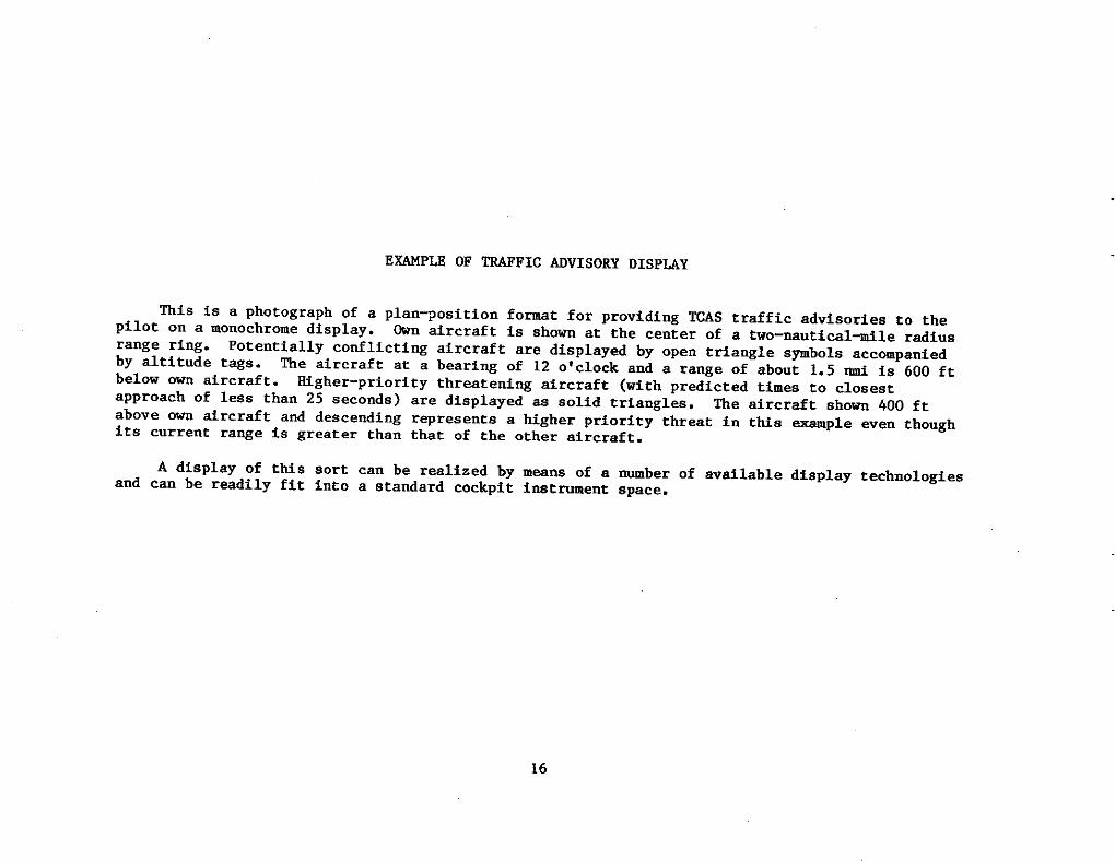
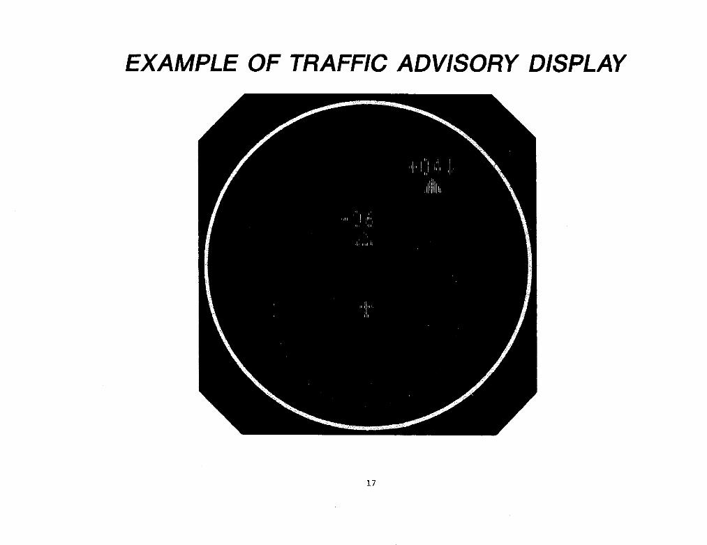
EMPLE OF WFIC AOVISORY DISPLAY
fiis is a photograph of a plan~osition fomat for providing US traffic advisories to thepilot on a monochrome display. Own drcraft is show at the center of a two-nautical+le radiusrange ring. Potentially conflicti~ aircraft are displayed by open triangle s~bols accompanied
by altitude tags. me aircraft at a bearing of 12 o’clock and a range of about 1.5 @ is 600 ftbelow ~ drcraft. Mgher-priority threatening aircraft (with predicted times to closest
apprOach of less than 25 seconds) are displayed as solid triangles. me aircraft ahon 400 ftabove ~ Arcraft and descending represents a higher priority threat in t~s ~mnple even thoughits current ra~e is greater than that of the other aircraft.
A display of ttis sort can be realized by means of a ~ber of available display technologiesand can be resdily fit into a standard cockpit imtmment space.
16
EXAMPLE OF TRAFFIC ADVISORY DISPLAY
17
WCO~NOATIONS FROM ENCOONTER OATA BASE ANALYSIS
Consideration of the itiomation derived from analyaia of the 31 encounters in the Navaltraining data base as well as e~erience from airborne flight tests leads to several conclusions.
First, since a significant fraction of the hazardous encounters involve civil aircraft, it ishighly desirable that the collision avoidance system for the’Navy trtiners have the capability todetect and provide protection against civil aircraft. Since most civil drcraft that cotilict tithNavy trainers ti11 have transponders tith encoding altimeters, a collision avoidance systernthat
operates by detecting civil transponders would be adequate in this regard. Such a system could alsoalert the pilot to the presence of aircraft tith non–altitude-repo rting transponders.
Second, it is important that the collision avoidance system provide a reliable suneillancera~e of about 3.5 W. Greater detection ra~es would increase the cost of.the equipment whileproviding little additional collision avoidance benefit. Lesser detection ranges would not protectagainst head-on encounters between T-34CS.
~ird, sume sort of plan-position display including ra~e, bearing, and altitude is recommendedbecause there is a high incidence of multiple-aircraft encounters in the traidng environment. Sucha display facilitates the tisual detection of traffic by the pilot and helps him to distinguishbetween aircraft. Furthermore, as shown in the previous figure, it is a simple mt ter to code the
display to clearly indicate which of the targeta is moat threateni~.
Finally, the analysis of the data on the 31 encounters provided to Mncoln Laboratoryindicates that there is less need for a collision avoidance device for the ~-57 helicopter. A
decision to equip the ~-57 should be based on review of a larger body of encounter data.
18
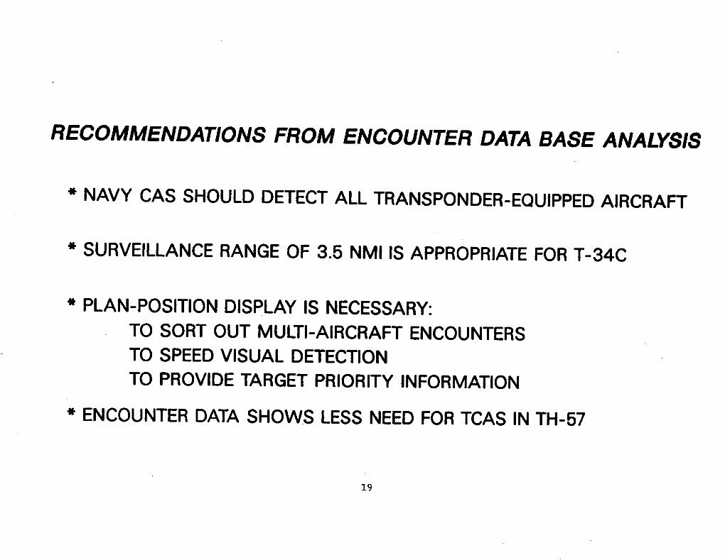
RECOMMENDATIONS FROM ENCOUNTER DATABASE ANALYSIS[
* NAVY CAS SHOULD DETECT ALL TRANSPONDER-EQUIPPED AIRCRAFT I
* SURVEILLANCE RANGE OF 3.5 NMI IS APPROPRIATE FOR T-34C
* PLAN-POSITION DISPLAY IS NECESSARY:I
TO SORT OUT MULTI-AIRCRAFT ENCOUNTERSTO SPEED VISUAL DETECTIONTO PROVIDE TARGET PRIORITY INFORMATION
* ENCOUNTER DATA SHOWS LESS NEED FOR TCAS IN TH-57 I
19
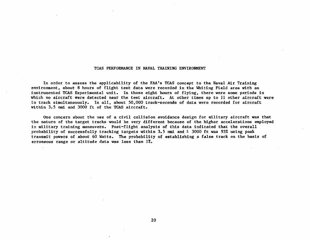
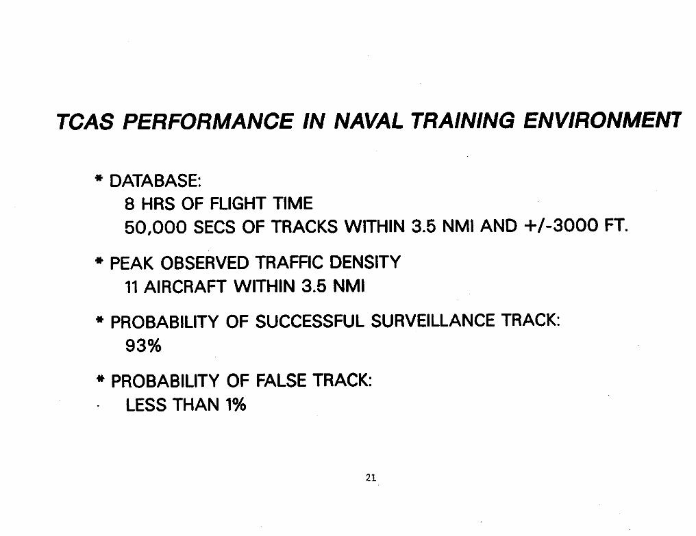
TCAS PERFOMCE IN NAVAL TRAINING ENVIROMNT
In order to assess the applicability of the FM’s TWS concept to the Naval Mr Trainingenviromnent, about 8 hours of flight test data were recorded in the Whiting Field area tith aninstmmented ~S &perimental utit. In those eight hours of flying, there were some periods inw~ch no aircraft were detected near the test aircraft. At other times up to 11 other tircrsft werein track simultaneously. In s1l, about 50,000 track-seconds of data were recorded for drcraftwithin 3.5 ti snd 3000 ft of the ~AS aircraft.
tie concern about the use of a civil collision avoidance design for tilita~ aircraft was thatthe nature of the target tracks would be very different because of the Mgher accelerations -ployedin tilita~ training mneuvers. Post-flight analysia of this data indicated that the overallprobability of successfully tracking targets tithin 3.5 d and * 3000 ft was 93% using peaktranstit powers of about 60 Watts. Tbe probability of establishing s false track on the basis oferroneous range or altitude data was less thsn 1%.
-1
20
TCAS PERFORMANCE
* DATABASE:8 HRS OF FLIGHT TIME50,000 SECS OF TRACKS WITHIN 3.5 NMI AND +/-3000 FT.
* PEAK OBSERVED TRAFFIC DENSITY
11AIRCRAFT WITHIN 3.5 NMI
* PROBABILITY OF SUCCESSFUL SURVEILLANCE TRACK:93%
* PROBABILITY OF FALSE TRACK:
LESS THAN 1%
21
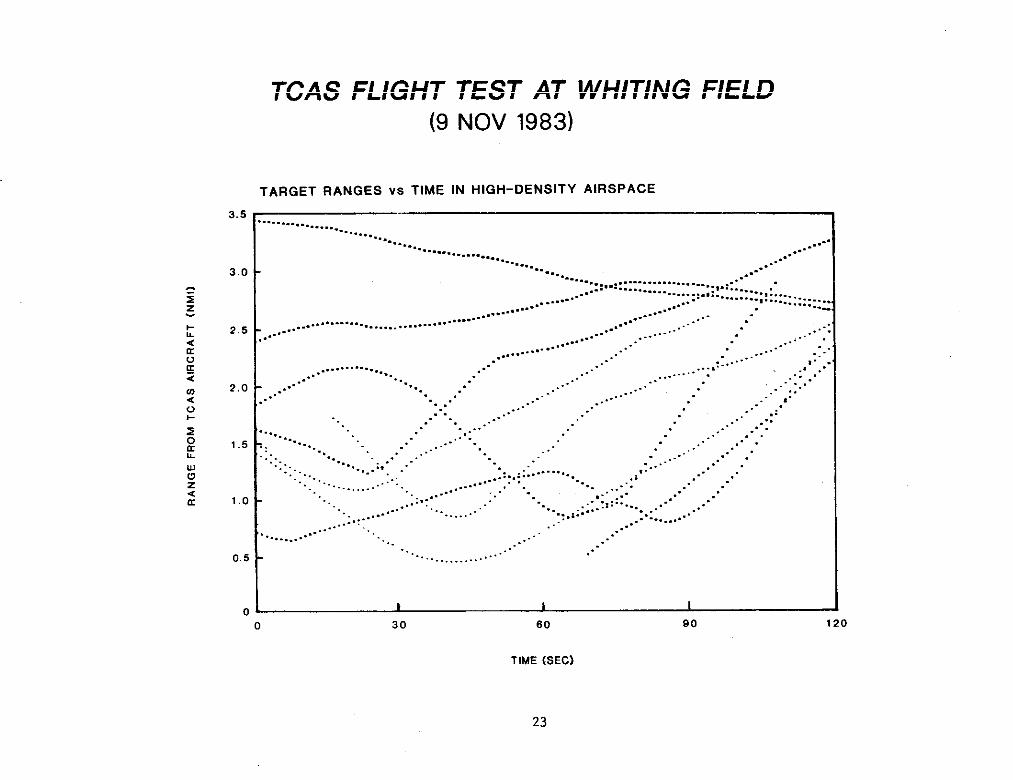
TCAS FLIGHT ~ST AT WITING FIELD
This is an cxmple of data from the %iting Field area on 9 November 1983. ~is plot shws the
range versus time of all of the tracked drcraft at to 3.5 d tithin a 2+nute time period.Between 70 and 90 seconds there are a total of 9 drcraft in track. &ce each track haa started,the tracki~ is perfect tithin t~s 2+nute interval. There are no holes or apparent fdse tracks.It is evident from t~s data that many of the targets were executi~ relatively severe msneuvers.Typical range trajectories for civil tircraft appear ~ nearly ideal parabolaa as the detectedaircraft flies paat the TWS aircraft. h exmple of such a trajecto~ is the one that passedwithin about O.5 d at about 40-seconds into t~s plot. In civil tirspace one seldom aeea atrajecto~ showi~ an increase in ra~e followed by a period of decreaei~ ra~e. Yet euch
trajectoriea appear repeatedly in the ~ti~ Field data, itiicati~ that the tracked aircraft weremaneuvering tith high accelerations. ~though the tracker design used in the ~S equipment was notoptitized for such trajectories, it was found that in almoat all imtanc~ the ~S tracker was able
to follow the accelerations of the filita~ drcraf t. The ody consistent ftilure occurred when thetracked Arcraft’s vertical rate =ceeded 6000 ft/dn. ~ia limitation can be easily corrected by atinor paremeter cha~e in the ~AS tracker altitude correlation tindows.
woz<E
3.5
3.0
2.5
2,0
1.5
1.0
0.5
0
TCAS FLIGHT(9
TEST AT WHITING FIELDNOV 1983)
TARGET RANGES VS TIME IN HIGH-DENSITY AIRSPACE
o 30 60 90 120
TIME {SEC)
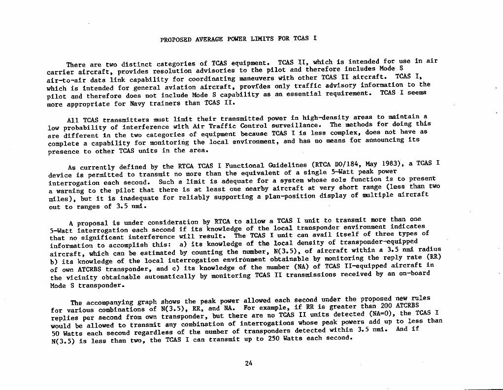
PROPOSED A~RAGE POWRR L~ITS FOR TSAS I
There are two distinct categories of T~ equipmnt. TWS 11, which is intended for use in aircarrier aircraft, provides resolution advisories to the pilot and therefore includes ~de Sair-to-air data link capability for coordinating =neuvers tith other T~S II aircraft. TCAS I,
which is intended for general aviation aircraft, provfdes only traffic adviaory infOr=tiOn tO thepilot and therefore does not include Wde S capability as an essential requirement. T~S I seemmore appropriate for NSU trainers than TMS 11.
Ml TCAS tranadt ters ws t lidt their transdt ted power in bigh+ensity areas to mintain alow probabi lity of interference with M r Traffic @ntrol surveillance. me *thOds fOr dOing thisare different in the two categories of equipment becauae T~S I ia less cOmPlex, dOes nOt have ascomplete a capability for monitoring the local environment, and has no mans for announcing itspresence to other T~S units in the area.
As currently defined by the RTCA TCAS I Functional Widelines (RTCA DO/184, my 1983), a TCAS Idevice is perdtted to transmit no mre than the equivalent of a single 5+at t peak Powerinterrogation each secOmd. Such a Ii&t is adequate for a system whose SOle fUnCtiOn is tO Presefi
a warning to the pilot that there is at least one nearby Wrcraft at very short range (less than two
tiles ), but it is inadequate for reliably supporting a plan70siti0n display Of ~ltiPle aircraftout to ranges of 3.5 nti.
A proposal is under consideration by RTW to allow a TM I unit to transtit more than one5-Watt interrogateion each second if its knowledge of the local transponder environment indicatesthat no significant interference till result. The TM I utit @n avail itself of three types of
infomtion to accomplish this: a) its knowledge of the local density of transponder-quipped
aircraft, which can bs estimted by counting the nmber, N(3.5), of aircraft within a 3.5 nti radiusb) its knowledge of the local interrogation environ=nt obtaimble by mnitoring the rePIY rate (~)
of ow AT~S transponder, and c) ite knowledge of the number (NA) of TaS II+quipped aircraft inthe vicinity obtainable automatically by monitoring T~S II trans~ssiOns received by an On-bOardMode S transponder.
The accompanying ~aph shows the peak power allowed each second under the proposed new rolesfor various combinations of N(3.5), RR, and WA. For exa~le, if RR is greater than 200 ATCRRS
replies per second from om transponder, but there are no TM 11 unite detected (NA=O), the T@S I
would be allowed to transmit any combination of interrogations whose peak powers add UP to less than50 Wat ta each second regardless of the number of transponders detected ~thin 3.5 n~. ~d ‘fN( 3. 5) iS less than two, the TWS I can tramstit UP tO 250 Watts each secOnd.
1 24*
[
PROPOSED AVERAGE POWER L/MITS FOR TCAS I
RR Is reply rate of own ATCRBS transponderNA Is number of TCAS II units detected by own MODE S transponder
260
200
160
‘H” ’00
6a
.-— —————---- .--- 0----------- ---’, 1 I * I I I
o 1 2 3 4 6 6 ? 8 9 10
N 3.5 (Numbar of aircraft datected within 3.5 nmi)
25 loo2e4

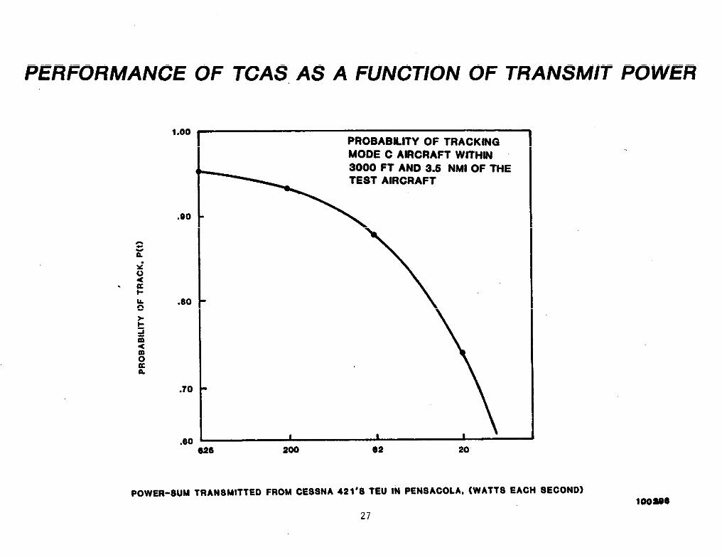
PERFORMANCE OF TCAS AS A FUNCTION OF TRANSMIT P~R
The TCAS e~erimental unit that was flom to ~iting Field transmitted a sequence ofinterrogation of descending power each second and recorded the replies elicited by each Of theseinterrogation. Each of these interrogation was preceded by a lower~ower suppression pulse tO
lidt the number of transponders that replied to it. This scheu is know as “’whisper-bout” andenables TCAS to separate mltiple targets so that their replies do not overlap and garble eachother. *cause of this sequence, it was possible, by post-flight amlysis of the data, to simlatea TCAS unit of peak transmit power ranging from that of a TCAS 11 to that of a low power TCAS 1.The accompanying figure compares the track probability of the ~U when operating at the ~ni~mtranatit power characteristic of TCAS II equipment (a peak power of approximately 125 W and aninterrogation power-urn of 625 Watts each second) tith the perfor=nce when operating ~thpower-sums of 200, 62, and 20 Watts each second. In deriving the probability of track for this
plot, the eatimte of the true presence of a target was based on a ~nual analysis Of all Of thereplies received from that target. It is seen that the overall probability of track waa not
strongly affected by the transfit power until the power-sum was reduced belOw abOut 100 Watta eachsecond. Thus, a desi@ that complies with the proposed guidelines for TCAS I could provide.adequate
performance in the Whiting Field environment provided that WA, the nuber of TCAS 11 units in the
area, is SW1l enough so that the interrogateion power can k increased to 100 Watts each secOnd.This requires a means of mnitoring WA. Monitoring can either bs accomplished by setting W to afixed value that ia certain to not be exceeded in the training airspace or by including a Mode Stransponder as part of the TCAS I installation.
26
PERFORMANCE OF TCAS AS A FUNCTION OF TRANSMIT POWER
1.00
( L
.00
.60
.?0
.60e25
PROBABILITY OF TRACKWQMODE C ARCRAFT W~HN3000 FT AND 3.5 NMt OF THETEST AIRCRAFT
I I Ie2 20
POWER-SUM TRANSMITTED FROM CESSNA 421’8 TEU IN PENSACOLA, (WATTS EACH SECONO)
27
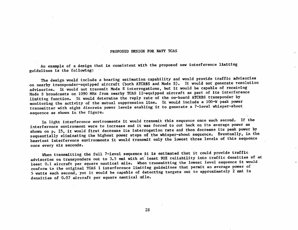
PROPOSED DESIGN FOR NA~ TUS
An -pie of a design that is comist ent tith the proposed~idelines is the followiug:
nsw interference lititing
The design would include a beari~ estimation capability and would provide traffic advisorieson nearby transponder-equipped tircraft (both A~RES and Mode S). It would not generate resolutionadvisories. It would not transtit Mode S intarrogations, ht it would be capable of receivi~Mode S broadcasts on 1090 - from nearby TWS II-equipped aircraft as part of its interferencelimiting function. It would detetine the reply rate of the on-board ATCRRS transponder by
monitori~ the activity of the mtual suppression line. It would include a 1OO-W peak powertransfitt er titb eight discrete power levels enabli~ it to generate a 7-level whisper-shoutsequence as shon in the figure.
In light interference environments it would transtit thfs sequence once each second. If theinterference environment were to increase and it was forced to cut back on its average power as
shorn on p. 25, it would first decrease its interrogation rate and then decrease its pe~ power by
sequentially elitinating the Mghest power steps of the w~sper-shout sequence. Eventually, in the
heaviest interference environments it would transfit ofly the lowest three levels of ttis sequence
once every six seconds.
men transdtting the full 7-level sequence it is esti~ted that it cOuld prOvide traffic
advisories on transponder out to 3.5 ti tith at”last 90% reliability intO traffic densities Of atleast 0.1 aircraft per square nautical tile. When transmitti~ the lowest l-cl sequence it would
conform to the original ~AS I interference lititing @delines that Peat an average POwer Of5 “atts each second, yet it would be capable of detecting targets Out tO aPPrOfimatelY 2 ~ in
densities of 0.07 tircraft per square mutical mfle.
I
I
PROPOSED DESIGN FOR NAVY TCAS(WHISPER -SHOUT SEQUENCE)
Sm lN~A~ON $mPRES910NWM2ER POWR (row) POWER (~W)
{7 20
e 18
6 16
4 %4
3 12
2 10
1 8
FIR9T l~ROeA~ON
Ar \
le
14
12
10
8
e
8 .,.1
8 ...1
6. ..1
al. . .S.. .l
8...1
;. ..,.1
sI I t:::::::s 10 16 20
mw
SECOND lmRROGATION
I .,,.. ......... ................ --wzm~
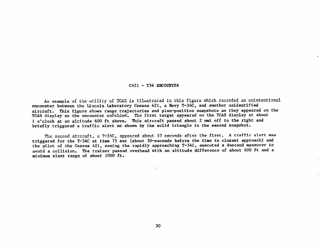
C421 - ?34 ENCO-R
An =mple of the utility of TCAS is illustrated in this figure w~ch recorded an unintentionalencounter between the Uncoln kborat oq Cessna 421, a Nav T-34C, and another unfdentifiedaircraft. This figure shows range trajectories and plan~osition snapshots as they appeared on theTCAS display as the encounter unfolded. The first target appeared on the TCAS display at about
1 o’clock at an altitude 600 ft above. This aircraft passed about 2 W off to the right andbriefly triggered a traffic alert as show by the solid triangle in the second snapshot.
The second aircraft, a T-34C , appeared about 10 seconds after the first. A traffic alert wastriggered for the T-34C at time 75 sec (about 30-seconds before the time to cloaeat approach) andthe pilot of the Cessna 421, seeing the rapidly approaching T-34C, executed a descend ~naver tOavoid a collision. The trainer passed overhead tith an altittie difference of about 600 ft and afinimum slant range of about 1000 ft.
30
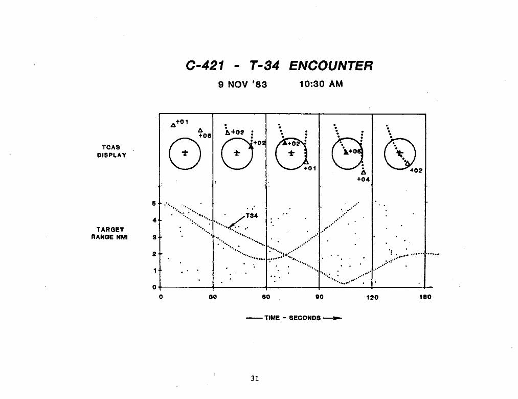
C-421 - T-34 ENCOUNTER
9 NOV ’83 10:30 AM
*to 1
Atot
TCASOISPLAY o*
s1............................,..,4 ...”.......
TARGET ..
RANOE NMI s .. ..’
2
1
L
. . .
0
:A+02 :
.
0
●to
*
.:.~?. . ... .
. .. .. ... . ..
. .. . .. .. ... ... . .. ..
.,.,.
. . .. .
:.. “.:
0+02 :
●
+01
. .
...... ..
‘,,..., ...... .,,......’’ .. .. ...
. . ......
. .
‘... :. “..b o:.. ...~+o .%
“.
i +0
+04
L,....................” ,
,,... . .. .
. ..; .
. . .... .. . :......,
.. .. ... . . ... .. ,
. .. . . .... .. .... . ... ...
. .... .. .. . .
0 so so 90 120 1s0
—TIME - SECONOS _
31
AIRCRAFT INSTMUTION CONSTRAINTS
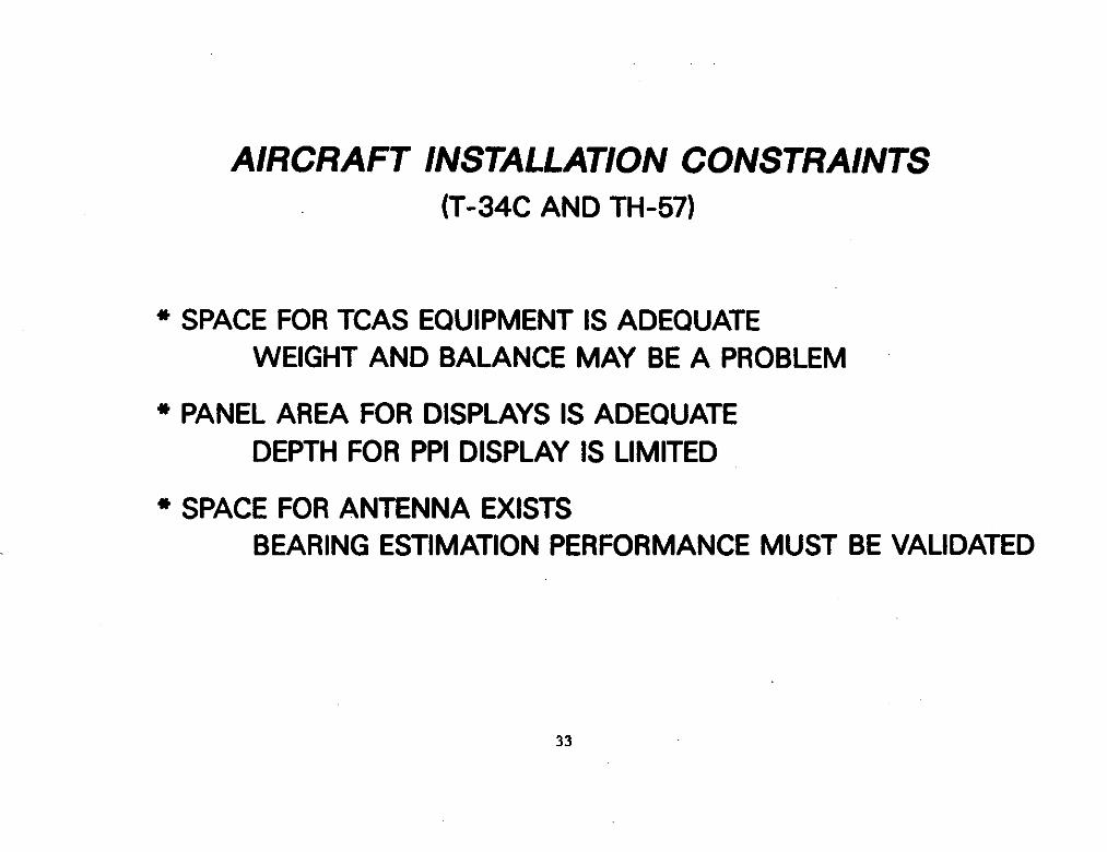
The final activity undertaken during the Hncoln bboratory visit to Nhiting Field was aphysical impection of the WW Training tircraft. It was concluded that, although there appears to
be adequate space for installation of TCAS electronics, displays, cabIing, and antenms, a tinorweight-and-balance adjustment my be necessary to accommodate the TCAS equipment.
There appears to be adequate panel area for TCAS displays in both the fore and aft cockpitsof the T-34C and in the single cockpit of the TS-57. Panel depth for a traffic advisory display
ia aomwhat lifited, but should be adequate if a atitably shallow display is provided.
There is adequate physical space for mounting the TCAS antenms, which consist of a small,top~ounted, four-element array for direction-f indi~ and a bottom-ounted monopole. However, the
ground plane for the direction-finding antenna is not aa large or as unobstmcted as would bepreferred. Before proceeding tith a procurement, direction-finding perfo~nce should be verifiedby measurwent using a test antenna mounted on the airfraes of the training tircraft.
..--.— . -—.-—— .
AIRCRAFT INSTALLATION CONSTRAINTS
(T-34C AND TH-57)
#
* SPACE FOR TCAS EQUIPMENT IS ADEQUATEWEIGHT AND BALANCE MAY BE A PROBLEM
I * PANEL AREA FOR DISPLAYS IS ADEQUATE.
1DEPTH FOR PPI DISPLAY IS LIMITED
~-
* SPACE FOR ANTENNA EXISTSBEARING ESTIMATION PERFORMANCE MUST BE VALIDATED
,...a.
33
I
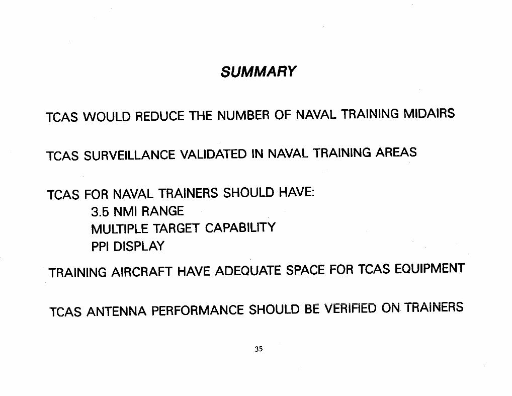
A review of selected tidair collision statistics from the Wval &r Trtining Co~nd indicatesthat the fiaffic Wert and Collision Avoidance Systa (TCAS) recently developed by the FAA would be
highly effective in reducing the incidence of tidair collisions and dangerous encounters in thenaval traifing environment.
Live flight testing of ~erimental ~AS equi~ent at Wting &val Mr Station showed thatequipment sitilar to the FAA ts TUS I category (intended for general aviation tircraft) wouldprovide reliable suneillance of essentially dl threateti~ afrcraft in naval traini~ airapace.
The recommended ~S design would provide a au~dllance range of 3.5 h and a target bearingestimation capability atitable for locating a target to tit~n one clock position. The equipment
should be capable of displaying mltiple targets to the pilot on a plamposition display that iscoded to provide an indication of target threat priority.
The T34< and TS-57 traiting tircraft have adequate apace for ~S equipment and displays.However, the perfomance of the ~S directiomf inding antenna should be verified qerimentally onthe airfrmes of the trtining aircraft.
34
SUMMARY I
TCAS WOULD REDUCE THE NUMBER OF NAVAL TRAINING MIDAIRS
1
TCAS SURVEILLANCE VALIDATED IN NAVAL TRAINING AREASI
TCAS FOR NAVAL TRAINERS SHOULD HAVE:3.5 NMI RANGEMULTIPLE TARGET CAPABILITYPPl DISPLAY
TRAINING AIRCRAFT HAVE ADEQUATE SPACE FOR TCAS EQUIPMENT
TCAS ANTENNA PERFORMANCE SHOULD BE VERIFIED ON TRAINERS
35