![Comparison of LHC Collimation Setups with Manual and Semi-automatic Collimator Alignment · 2018. 4. 1. · Beams. In Proceedings of HB2010, Morschach, Switzerland. [3] D. Wollmann](https://static.fdocuments.in/doc/165x107/61180215e7ba48776b5f2b07/comparison-of-lhc-collimation-setups-with-manual-and-semi-automatic-collimator-alignment.jpg)
Collimation for LHC High Intensity Beams -...
50
Collimation for LHC High Intensity Beams R.W. Aβmann CERN 26/09/2010 HB2010, Morschach Ralph Assmann HB2010 1
Transcript of Collimation for LHC High Intensity Beams -...

Collimation for LHC High
Intensity Beams
R.W. Aβmann
CERN
26/09/2010
HB2010, Morschach
Ralph Assmann HB2010 1

The Collimation Project Team
& Close Collaborators
• Results on phase I collimation are outcome of lot of work performed over last 8 years by the
following CERN colleagues:
O. Aberle, J.P. Bacher, V. Baglin, G. Bellodi, A. Bertarelli, R. Billen, V. Boccone,
A.P. Bouzoud, C. Bracco, H. Braun, R. Bruce, M. Cauchi, N. Hilleret, E.B. Holzer,
D. Jacquet, J.B. Jeanneret, J.M. Jimenez, M. Jonker, Y. Kadi, K. Kershaw, G. Kruk,
M. Lamont, L. Lari, J. Lendaro, J. Lettry, R. Losito, M. Magistris, A. Masi, M. Mayer,
E. Métral, C. Mitifiot, R. Perret, S. Perrolaz, V. Previtali, C. Rathjen, S. Redaelli,
G. Robert-Demolaize, C. Roderick, S. Roesler, A. Rossi, F. Ruggiero, M. Santana,
R. Schmidt, P. Sievers, M. Sobczak, K. Tsoulou, G. Valentino, E. Veyrunes,
H. Vincke, V. Vlachoudis, T. Weiler, J. Wenninger, D. Wollmann, …
• Crucial work also performed by collaborators at:
EuCARD/ColMat partners, TRIUMF (D. Kaltchev), IHEP (I. Baishev & team), SLAC
(T. Markiewicz & team), FNAL (N. Mokhov & team), BNL (N. Simos, A. Drees &
team), Kurchatov (A. Ryazanov & team).
Ralph Assmann HB2010 2

Outline
• The Energy and Intensity Frontier at LHC
• The LHC Collimation System
• Collimation Setup
• Performance: Simulation and Measurement
• Outlook: Upgrades
• Conclusion
Ralph Assmann HB2010 3

Parameters for LHC Luminosity Production
Ralph Assmann HB2010 4

Parameters for LHC Luminosity Production
Ralph Assmann HB2010
b* = IP beta function (bx=by)
en = norm. transv. emittance
Np = protons per bunch
frev = revolution frequency
F = geometrical correction
m0 = rest mass, e.g. of proton
c = velocity of light
constant
Fixed tunnel length: low
LHC revolution frequency
makes it harder to produce
lumi (compared to Tevatron)
Beam-beam:
Fine with no-
minal bunch
charge! Can
put more…
At the moment set to 3.5 m in all
IR’s (2m reached): better margins for
operation, collimation and protection.
Limit is ~1.2 m at 3.5 TeV. However, then
very tight tolerances!
Achieved
normalized
emittance
40% below
nominal!
LHC luminosity is increased
via stored energy 2.8 MJ!
Go up by increasing number of
bunches!
Extrapolating from 2.8 MJ: No
show-stopper 30 MJ (2010 goal).
Go up not too fast & not too slow...
5
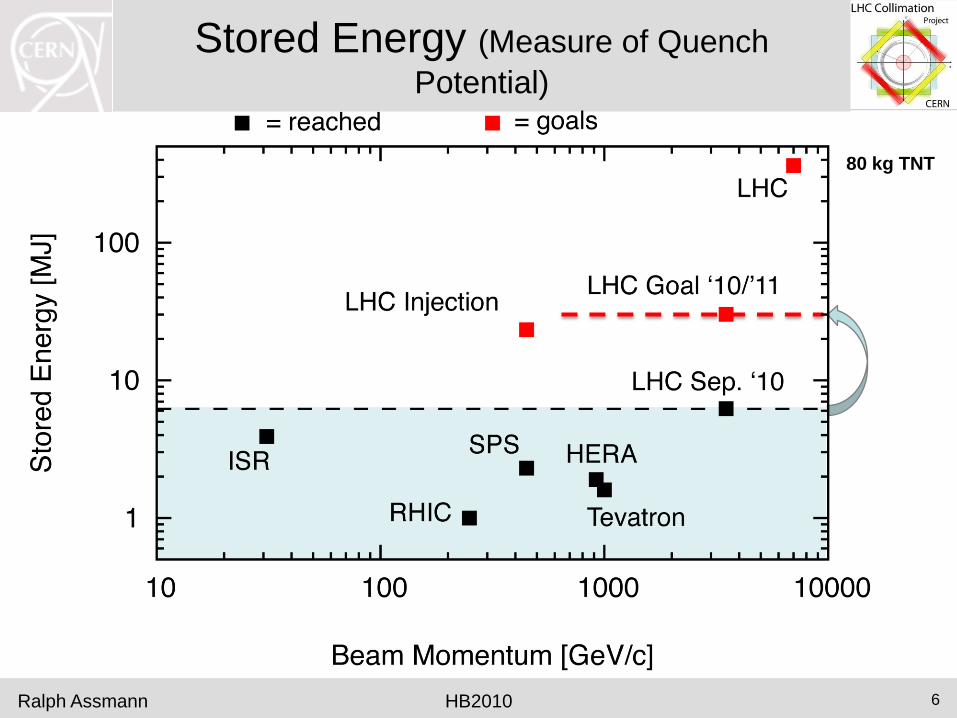
Stored Energy (Measure of Quench
Potential)
Ralph Assmann HB2010
80 kg TNT
6

LHC Parameters (for Reference)
• Beam energy: 3.5 TeV frontier, 7 TeV in 2013
• Bunch intensity: 1.1e11 nominal, can put more
• Number of bunches: 104
• Norm. emittance: 2.2 mm 60% of nominal
• IP beta value: 3.5 m limited for larger margins
• Stored energy: 6.2 MJ frontier, 30 MJ in 2010/11
• Peak luminosity: 3.5 x 1031 cm-2 s-1 factor 3 to go in 2010
• Luminosity lifetime: ~25 h
• Availability: ~85 % (max. weekly)
• Time in physics: 40.2 % (max. weekly)
Ralph Assmann HB2010 7

Ralph Assmann
Proton Losses
• LHC: Ideally no power lost (protons stored with infinite lifetime).
• Collimators are the LHC defense against unavoidable losses:
– Irregular fast losses and failures: Passive protection.
– Slow losses: Cleaning and absorption of losses in super-conducting
environment.
– Radiation: Managed by collimators.
– Particle physics background: Minimized.
• Specified 7 TeV peak beam losses (maximum allowed loss):
– Slow: 0.1% of beam per s for 10 s 0.5 MW
– Transient: 5 × 10⁻⁵ of beam in ~10 turns (~1 ms) 20 MW
– Accidental: up to 1 MJ in 200 ns into 0.2 mm2 5 TW
HB2010 8

Quench Limit of LHC Super-Conducting Magnets
Ralph Assmann HB2010
Beam
362 MJ
SC Coil:
quench limit
5-30 mJ/cm3
56 mm
Nominal design at 7 TeV
9

Quench Limit of LHC Super-Conducting Magnets
Ralph Assmann HB2010
Beam
6.2 MJ
SC Coil:
quench limit
15-100 mJ/cm3
56 mm
Situation at 3.5 TeV (on September 26, 2010)
LHC beam is about
60,000,000 times above
quench limit of super-
conducting magnets
(per cm3)! Of course,
diluted…
Not a single beam-induced
quench at 3.5 TeV yet!
10

Energy Density (Measure of Damage Potential)
Ralph Assmann HB2010
Damage
limit
copper
Damage
limit CFC (collimator)
11

Intensity Frontier at LHC:
Role of Collimation
• All other SC proton colliders had an important number of beam-induced
quenches while pushing up to the MJ regime.
• LHC reached 3 times the world record in stored energy per beam within 6
months and without a beam-induced quench with stored beam.
• How was this achieved?
– Highly efficient, 4 stage collimation system in the LHC.
– Tight collimation all through injection, ramp, squeeze and collision.
– Catches safely all losses that occur while intensity is increased.
– This includes “normal” losses (scattering, emittance growth, diffusion,
…) and losses with equipment failures.
Ralph Assmann HB2010 12

A Look at Record Fill This Weekend
• Intensity increased by factor 2 to 1.11e13 protons per beam.
• Peak luminosity: 3.5 × 1031 cm-2 s-1
Ralph Assmann HB2010 13
First 6 MJ Physics: 17 hours, ~20% intensity loss
Beam energy
Beam Intensities

Losses Around the Ring (3.5 TeV, End Record Fill 26.9.2010, t > 75 h)
Ralph Assmann
AT
LA
S
AL
ICE
CM
S
LH
C-b
0 – 27 km
Momentum
Collimation Betatron
Collimation
Beam 1
Beam 2
Essentially all losses at collimators No beam dump or quench!
3.5
3.0
2.5
2.0
1.5
1.0
0.5
0.0
HB2010 14
× 10-4 Gy/s

Losses Around the Ring (3.5 TeV, End Record Fill 26.9.2010, t > 75 h)
Ralph Assmann
AT
LA
S
AL
ICE
CM
S
LH
C-b
0 – 27 km
Momentum
Collimation Betatron
Collimation
Beam 1
Beam 2
Details can be seen in logarithmic scale!
Du
mp
Logarithmic scale!
HB2010 15
Gy/s
10-4
10-5
10-6

Cleaning All the Time…
• With high LHC beam intensity we see unavoidable beam losses
constantly (see example for lifetime > 75 hours).
• We can characterize losses. E.g. losses for beam 1 mostly in momentum
cleaning had a few RF cavity trips. Losses for beam 2 mostly in
betatron cleaning no RF trips for beam 2.
• Essentially all losses intercepted at primary collimators in betatron
and momentum cleaning insertions!
• Very small leakage to outside cleaning insertions.
• Some local losses occur in the experimental insertions (visible on
logarithmic scale): luminosity-driven losses, p-p collisions.
• In addition: rare beam dumps due to tiny, fast losses in middle of arc (10
events so far rare dust particles?). Not discussed here…
Ralph Assmann
How Does Collimation Work and Does it Work as Predicted?
HB2010 16

Outline
• The Energy and Intensity Frontier at LHC
• The LHC Collimation System
• Collimation Setup
• Performance: Simulation and Measurement
• Outlook: Upgrades
• Conclusion
Ralph Assmann HB2010 17

Ralph Assmann
The LHC Collimation System
• Collimators must intercept any
losses of protons such that the rest
of the machine is protected („the
sunglasses of the LHC“):
> 99.9% efficiency!
• To this purpose collimators insert
diluting and absorbing materials into
the vacuum pipe.
• Material is movable and can be
placed as close as 0.25 mm to the
circulating beam!
• Nominal distance at 7 TeV:
≥ 1 mm.
Top view
HB2010 18

The Carbon Fiber Collimator closest to beam: primary (TCP) and secondary (TCS) collimators
Ralph Assmann
Parameter Unit Specification
Jaw material CFC
Jaw length TCS
TCP
cm
cm
100
60
Jaw tapering cm 10 + 10
Jaw cross section mm2 65 × 25
Jaw resistivity μΩm ≤ 10
Surface roughness μm ≤ 1.6
Jaw flatness error μm ≤ 40
Heat load kW ≤ 7
Jaw temperature °C ≤ 50
Bake-out temp. °C 250
Minimal gap mm ≤ 0.5
Maximal gap mm ≥ 58
Jaw position control μm ≤ 10
Jaw angle control μrad ≤ 15
Reproducibility μm ≤ 20
2003 Specification HB2010 19
360 MJ proton
beam
1.2
m

Precisions Control & Movements
Ralph Assmann
Accurate stepping motors control
jaw positions versus time!
HB2010 20
TCSG (fiber-
reinforced
graphite) TCT (tungste
n)
Side view at one end
Moto
r
Motor
Temperature sensors
Gap opening (LVDT)
Gap position (LVDT) Resolver
Resolver
Reference Reference
Microphone
Vacuum tank
+ switches for IN, OUT, ANTI-COLLISION
CF
C
CF
C
Sliding table

Ralph Assmann
System Design
Momentum
Cleaning
Betatron
Cleaning
“Phase I”
108 collimators
& absorbers in
1st generation (only movable
shown in sketch)
HB2010 21

Multi-Stage Cleaning & Protection 3-4 Stages
Secondary
halo p
p e
p
Pri
mary
co
llim
ato
r Core
Unavoidable losses
Shower
Beam propagation
Impact
parameter
≤ 1 mm
Primary
halo (p)
e
p
Shower
p
Tertiary halo
Seco
nd
ary
co
llim
ato
r
Hig
h Z
co
ll
CFC CFC W/Cu W/Cu
Hig
h Z
co
ll
Super-
conducting
magnets
SC magnets
and particle
physics exp.
CFC collimator
Ralph Assmann HB2010 22

Multi-Stage Cleaning & Protection 3-4 Stages
Secondary
halo p
p e
p
Pri
mary
co
llim
ato
r Core
Unavoidable losses
Shower
Beam propagation
Impact
parameter
≤ 1 mm
Primary
halo (p)
e
p
Shower
p
Tertiary halo
Seco
nd
ary
co
llim
ato
r
Hig
h Z
co
ll
CFC CFC W/Cu W/Cu
Hig
h Z
co
ll
Super-
conducting
magnets
SC magnets
and particle
physics exp.
CFC collimator
Ralph Assmann HB2010 23

Multi-Stage Cleaning & Protection 3-4 Stages
Secondary
halo p
p e
p
Pri
mary
co
llim
ato
r Core
Unavoidable losses
Shower
Beam propagation
Impact
parameter
≤ 1 mm
Primary
halo (p)
e
p
Shower
p
Tertiary halo
Seco
nd
ary
co
llim
ato
r
Hig
h Z
co
ll
CFC CFC W/Cu W/Cu
Hig
h Z
co
ll
Super-
conducting
magnets
SC magnets
and particle
physics exp.
CFC collimator
Ralph Assmann HB2010 24

Multi-Stage Cleaning & Protection 3-4 Stages
Secondary
halo p
p e
p
Pri
mary
co
llim
ato
r Core
Unavoidable losses
Shower
Beam propagation
Impact
parameter
≤ 1 mm
Primary
halo (p)
e
p
Shower
p
Tertiary halo
Seco
nd
ary
co
llim
ato
r
Hig
h Z
co
ll
CFC CFC W/Cu W/Cu
Hig
h Z
co
ll
Super-
conducting
magnets
SC magnets
and particle
physics exp.
CFC collimator
Ralph Assmann HB2010 25

Phase I in Tunnel (Radiation-Optimized)
BEAM PIPES
COLLIMATOR
TRANSPORT ZONE
COLLIMATOR CABLE TRAYS
RADIATION-HARD CABLE PATH
WATER FEEDS
PHASE I/II
WATER
DISTRIBUTION
Ralph Assmann HB2010 26

Outline
• The Energy and Intensity Frontier at LHC
• The LHC Collimation System
• Collimation Setup
• Performance: Simulation and Measurement
• Outlook: Upgrades
• Conclusion
Ralph Assmann HB2010 27

Collimation Setup
• Collimation setup: Jaws are moved symmetrically
around the beam until jaws create ~equal beam
loss. Halo-based adjustment.
• Info from beam-based calibration: Beam center,
beam size variation from collimator to collimator.
• Injection: beam center and calibrated beam size
used to move collimators to +- N sigma around
the beam.
• Top energy: beam center and nominal beam size
(beta beat < 20%) used to move collimators to +-
N sigma around the beam.
• Target settings determined from simulations (see
table).
Ralph Assmann HB2010 28
BEAM
Reference
collimator

Collimation Setting Overview (in terms of b beam size, valid 12.6. – 30.8.2010)
Ralph Assmann
Ramp functions move smoothly from set 1 to set 2 during energy ramp!
3.5 TeV setup took ~30 h of beam time with single bunch of 1e11 p. Time distributed over 10 days with ~1
collimation shift per day.
HB2010 29

Settings Calculation
• The collimator settings are calculated (based on beam-based data) to:
– Provide good efficiency.
– Provide the correct collimator hierarchy (slow primary losses at primary
collimators).
– Protect the accelerator against the specified design errors.
– Provide continuous cleaning and protection during all stages of beam
operation: injection, prepare ramp, ramp, squeeze, collision, physics.
– Provide maximum tolerances to beam and various collimator families.
– Provide warning thresholds on all collimator axis positions versus time.
– Provide interlock thresholds on all collimator axis positions versus time.
– Provide interlock thresholds on all collimator gaps versus beam energy.
• Complex problem with some 100,000 numbers to control the system.
• Redundant calculation: time-dependent (ABP), energy-dependent (OP)
Ralph Assmann HB2010 30

Outline
• The Energy and Intensity Frontier at LHC
• The LHC Collimation System
• Collimation Setup
• Performance: Simulation and Measurement
• Outlook: Upgrades
• Conclusion
Ralph Assmann HB2010 31

Performance: Simulation and
Measurement • First step for redesign of LHC collimation system: Setup of parallel
simulation program and CPU cluster to numerically optimize the system.
• Maximum runs: 20,000,000 protons tracked over 200 turns
108 billion proton-km
• Imagine: Simulating a proton that travels 700 times the
distance sun-earth in an accelerator!
• Simulation included all magnetic elements and an aperture model with a
resolution of 0.1 m!
• Simulation includes halo proton generation, halo transport, proton-matter
interaction and aperture checks for each proton every 0.1m!
• Decisions taken based on simulations: material, length of jaws, reduced
number of primary collimators by 20%, reduced number of secondary
collimators by 25%, added tertiary collimators, …
• AP simulations complemented by FLUKA energy deposition!
Ralph Assmann HB2010 32

Ralph Assmann
Side Remark: Impedance Issue
Third look at impedance in Feb 03
revealed a problem:
F. Ruggiero
• Review LHC collimator-induced impedance (not thought to be problem).
• Surprise in 2003: LHC impedance driven by collimators, even metallic
collimators.
• LHC has an impedance that depends on the collimator settings!
• Predicted in detailed simulations (E. Metral et al) and found as predicted.
Stabilized with transverse damper and octupoles!
HB2010 33
Unstable regime

450 GeV: Cleaning Measurement Beam 1 – Horizontal (Qx crossing of 1/3 resonance)
HB2010
99.975%
Loss at primary
collimator
CL
EA
NIN
G
Measured 6 days after beam-based setup of collimators – no retuning…
Ralph Assmann 34

450 GeV: Cleaning Measurement Beam 1 – Horizontal (Qx crossing of 1/3 resonance)
HB2010
99.975%
Loss at primary
collimator
CL
EA
NIN
G
Measured 6 days after beam-based setup of collimators – no retuning…
Ralph Assmann 35

450 GeV: Cleaning Measurement Beam 1 – Horizontal (Qx crossing of 1/3 resonance)
HB2010
99.975%
Loss at primary
collimator
CL
EA
NIN
G
Measured 6 days after beam-based setup of collimators – no retuning…
Note losses on warm
magnets and vacuum
(red lines).
Maximum if colli-
mation works well! ~
1/3 of beam ends
here! Ralph Assmann 36
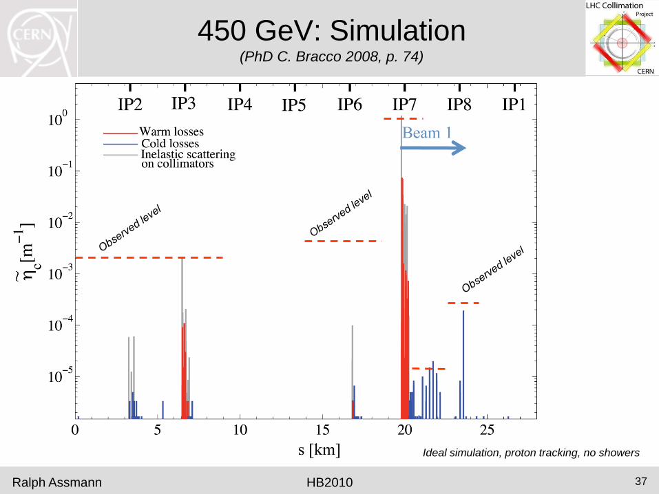
450 GeV: Simulation (PhD C. Bracco 2008, p. 74)
HB2010
Ideal simulation, proton tracking, no showers
Ralph Assmann 37

450 GeV: Cleaning Measurement Beam 2 – Horizontal (Qx crossing of 1/3 resonance)
HB2010
99.981%
Loss at primary
collimator
Measured 6 days after beam-based setup of collimators – no retuning…
Ralph Assmann 38

450 GeV: Simulation vs Measurement (Data 2009 - PhD G. Robert-Demolaize 2006, p. 114)
HB2010
Notes:
(1) As expected,
additional losses
from showers
behind primary
collimators.
(2) 3x higher than
simulated losses in
LSS7L SC magnets.
(3) 50x higher than
simulated TCDQ
losses setup.
(4) Additional loss
on TCT in IR5:
simulations at 450
GeV had TCT out.
(5) As expected
losses in IR3
correct simulation of
energy loss in IR7
collimators.
1
2
3
4 5
Simulation with worst case design orbit error, proton tracking, no showers
Ralph Assmann 39

450 GeV: Simulation vs Measurement (Data 2009 - PhD G. Robert-Demolaize 2006, p. 114)
HB2010
Notes:
(1) As expected,
additional losses
from showers
behind primary
collimators.
(2) 3x higher than
simulated losses in
LSS7L SC magnets.
(3) 50x higher than
simulated TCDQ
losses setup.
(4) Additional loss
on TCT in IR5:
simulations at 450
GeV had TCT out.
(5) As expected
losses in IR3
correct simulation of
energy loss in IR7
collimators.
1
2
3
4 5
Simulation with worst case design orbit error, proton tracking, no showers
Ralph Assmann 40

Measured Cleaning at 3.5 TeV (beam1, vertical beam loss, intermediate settings)
HB2010 Ralph Assmann
IR8 IR1 IR2 IR5
Mo
me
ntu
m
Cle
an
ing
Du
mp
Pro
tec
tio
n C
ol.
2m optics exposes IR’s as expected! Protected by tertiary collimators.
41

Simulated Cleaning at 3.5 TeV (beam1, vertical beam loss, intermediate settings)
Ralph Assmann HB2010 42

Meas. & Sim. Cleaning at 3.5 TeV (beam1, vertical beam loss, intermediate settings)
HB2010 Ralph Assmann
IR8
IR7
Confirms expected
limiting losses in SC
dispersion suppressor:
single-diffractive losses
43

Meas. & Sim. Cleaning at 3.5 TeV (beam1, vertical beam loss, intermediate settings)
HB2010 Ralph Assmann
IR8
IR7
Confirms expected
limiting losses in SC
dispersion suppressor:
single-diffractive losses
44

Betatron Cleaning: Stability
Over 10 Weeks
Ralph Assmann
3.5 TeV D. Wollmann et al
HB2010 45

Outline
• The Energy and Intensity Frontier at LHC
• The LHC Collimation System
• Collimation Setup
• Performance: Simulation and Measurement
• Outlook: Upgrades
• Conclusion
Ralph Assmann HB2010 46

Outlook: LHC Collimation Upgrades
Ralph Assmann HB2010 47
Cryo-Collimator
For Dispersion-
Suppressor
CERN
Rotatable high Z jaw
allows for multiple
damaging beam hits!
Collimator Jaws with
In-Situ Pickup Buttons
for Fast Setup

Phase 2 Coll. With SPS Beam Drifts Standard BLM-based Method – Observing Jaw-BPM’s
Ralph Assmann
Jaw-BPM
upstream
Jaw-BPM
downstream
Set gap center
Re-do BLM
based set-up
to follow
beam center
Brings also
back jaw-
BPM’s to
previous
reading!
after 15 min
Agreement BLM – jaw BPM:
10 – 20 mm level
Will solve many LHC issues!
Plot: D. Wollmann
EuCARD
HB2010 48

Conclusion
• The LHC collimation system has been designed, produced, installed and
commissioned over the last 8 years!
• Major effort to make it right, with strong support from various CERN
departments and outside collaborators. Biggest and most complex (also
most expensive) system built so far.
• LHC collimation works with expected performance level and has shown
an amazing stability over the last 2 months. Simulations were right!
• Collimation and beam cleaning allowed the LHC in establishing the
intensity frontier in 6 months (passing Tevatron, HERA, ISR, RHIC, …).
• Not a single quench with stored beam!
• Thanks to all the world experts helping with advice and support over the
years. Our success reflects the rapid progress in the field.
• Upgrades are being prepared to improve collimation by a further factor 5-
10 over next years.
Ralph Assmann HB2010 49

Pointers to Talks & Posters
Ralph Assmann HB2010 50
Other talks/posters on LHC
collimation-related topics:
S. Redaelli – Operational
Performance of Collimation
D. Wollmann – Collimation
Upgrade
M. Zerlauth – Machine
Protection
E.B. Holzer – Beam Loss
Monitors
A. Nordt – Beam Loss
Monitors
V. Kain – LHC Beam
Commissioning